Orkustofnun, Grensasvegur 9, Reports 2018 IS-108 Reykjavik, Iceland Number 8 1 ANALYSIS OF STUCK PIPE AND FISHING OPERATIONS: CASE STUDY OF OLKARIA GEOTHERMAL FIELD IN KENYA Victor Okello Atwa Kenya Electricity Generating Company, PLC. – KenGen P.O. Box 785-20117 Naivasha KENYA [email protected] ABSTRACT In geothermal development, drilling is one of the main activities carried out for exploration and appraisal and later for production in a fully developed field. Drilling constitutes of 35-50% of the total project cost. It is therefore vital to manage drilling costs and keep them low. Stuck pipe and fishing are considered non-productive and increase drilling costs by more than 15% on average, hence, should be avoided where possible. For every stuck pipe, there is a mechanism that leads to the incidence and a corresponding procedure to free the string. The success of stuck pipe management and fishing is evaluated by the time it takes to complete the whole process. Unsuccessful fishing operations end up in loss of equipment and resources including time and sometimes lead to well abandonment. This paper examines different stuck pipe mechanisms, which indications there are prior to the stuck pipe and how the operator should respond to each sticking incidence. Fishing methods and fishing tools are also presented in this paper. Finally, the paper explores stuck pipe incidences in Olkaria geothermal field, Kenya whereby 5 wells with stuck pipe incidences are analysed for possible causes of sticking and fishing operations that were carried out. The results are then discussed and recommendations are made to avert such situations in the future. 1. INTRODUCTION During the well drilling process, a drill string is used to transmit the weight and torque generated by the surface equipment to the bit. The drill string is composed of drill pipes, heavy weight drill pipes, drill collars and other bottom hole assemblies like stabilizers and bits. The weight and torque transmitted to the bit enables the formation to be drilled, creating a well. Occasionally, both the reciprocating (up and down) and the rotary movement is restricted leading to a stuck pipe. Stuck pipes may occur while drilling, making a connection, tripping, logging or during any kind of operation that takes place with equipment downhole (Schlumberger, 1997). When a stuck pipe arises, efforts are made to free the string and pull it out of hole as soon as possible. Part of the downhole equipment may be left in the hole either accidentally or intentionally and retrieved later in a process known as fishing. Stuck pipe and fishing operations are time consuming and require extra resources. Daily operating costs while fishing are 75% higher than the normal drilling operations- costs (Short, 1981). Understanding the stuck pipe mechanisms and fishing methods is key to minimizing stuck pipe incidences and the associated losses.

Welcome message from author
This document is posted to help you gain knowledge. Please leave a comment to let me know what you think about it! Share it to your friends and learn new things together.
Transcript

Orkustofnun, Grensasvegur 9, Reports 2018 IS-108 Reykjavik, Iceland Number 8
1
ANALYSIS OF STUCK PIPE AND FISHING OPERATIONS: CASE STUDY OF OLKARIA GEOTHERMAL FIELD IN KENYA
Victor Okello Atwa Kenya Electricity Generating Company, PLC. – KenGen
P.O. Box 785-20117 Naivasha KENYA
ABSTRACT
In geothermal development, drilling is one of the main activities carried out for exploration and appraisal and later for production in a fully developed field. Drilling constitutes of 35-50% of the total project cost. It is therefore vital to manage drilling costs and keep them low. Stuck pipe and fishing are considered non-productive and increase drilling costs by more than 15% on average, hence, should be avoided where possible. For every stuck pipe, there is a mechanism that leads to the incidence and a corresponding procedure to free the string. The success of stuck pipe management and fishing is evaluated by the time it takes to complete the whole process. Unsuccessful fishing operations end up in loss of equipment and resources including time and sometimes lead to well abandonment. This paper examines different stuck pipe mechanisms, which indications there are prior to the stuck pipe and how the operator should respond to each sticking incidence. Fishing methods and fishing tools are also presented in this paper. Finally, the paper explores stuck pipe incidences in Olkaria geothermal field, Kenya whereby 5 wells with stuck pipe incidences are analysed for possible causes of sticking and fishing operations that were carried out. The results are then discussed and recommendations are made to avert such situations in the future.
1. INTRODUCTION During the well drilling process, a drill string is used to transmit the weight and torque generated by the surface equipment to the bit. The drill string is composed of drill pipes, heavy weight drill pipes, drill collars and other bottom hole assemblies like stabilizers and bits. The weight and torque transmitted to the bit enables the formation to be drilled, creating a well. Occasionally, both the reciprocating (up and down) and the rotary movement is restricted leading to a stuck pipe. Stuck pipes may occur while drilling, making a connection, tripping, logging or during any kind of operation that takes place with equipment downhole (Schlumberger, 1997). When a stuck pipe arises, efforts are made to free the string and pull it out of hole as soon as possible. Part of the downhole equipment may be left in the hole either accidentally or intentionally and retrieved later in a process known as fishing. Stuck pipe and fishing operations are time consuming and require extra resources. Daily operating costs while fishing are 75% higher than the normal drilling operations- costs (Short, 1981). Understanding the stuck pipe mechanisms and fishing methods is key to minimizing stuck pipe incidences and the associated losses.
Atwa 2 Report 8
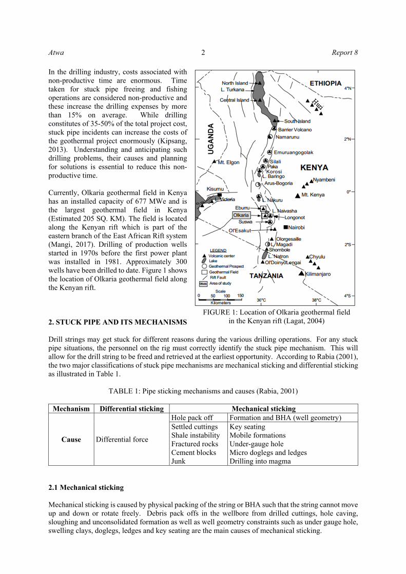
In the drilling industry, costs associated with non-productive time are enormous. Time taken for stuck pipe freeing and fishing operations are considered non-productive and these increase the drilling expenses by more than 15% on average. While drilling constitutes of 35-50% of the total project cost, stuck pipe incidents can increase the costs of the geothermal project enormously (Kipsang, 2013). Understanding and anticipating such drilling problems, their causes and planning for solutions is essential to reduce this non-productive time. Currently, Olkaria geothermal field in Kenya has an installed capacity of 677 MWe and is the largest geothermal field in Kenya (Estimated 205 SQ. KM). The field is located along the Kenyan rift which is part of the eastern branch of the East African Rift system (Mangi, 2017). Drilling of production wells started in 1970s before the first power plant was installed in 1981. Approximately 300 wells have been drilled to date. Figure 1 shows the location of Olkaria geothermal field along the Kenyan rift. 2. STUCK PIPE AND ITS MECHANISMS Drill strings may get stuck for different reasons during the various drilling operations. For any stuck pipe situations, the personnel on the rig must correctly identify the stuck pipe mechanism. This will allow for the drill string to be freed and retrieved at the earliest opportunity. According to Rabia (2001), the two major classifications of stuck pipe mechanisms are mechanical sticking and differential sticking as illustrated in Table 1.
TABLE 1: Pipe sticking mechanisms and causes (Rabia, 2001)
Mechanism Differential sticking Mechanical sticking
Cause Differential force
Hole pack off Formation and BHA (well geometry) Settled cuttings Shale instability Fractured rocks Cement blocks Junk
Key seating Mobile formations Under-gauge hole Micro doglegs and ledges Drilling into magma
2.1 Mechanical sticking Mechanical sticking is caused by physical packing of the string or BHA such that the string cannot move up and down or rotate freely. Debris pack offs in the wellbore from drilled cuttings, hole caving, sloughing and unconsolidated formation as well as well geometry constraints such as under gauge hole, swelling clays, doglegs, ledges and key seating are the main causes of mechanical sticking.
FIGURE 1: Location of Olkaria geothermal field in the Kenyan rift (Lagat, 2004)
Report 8 3 Atwa
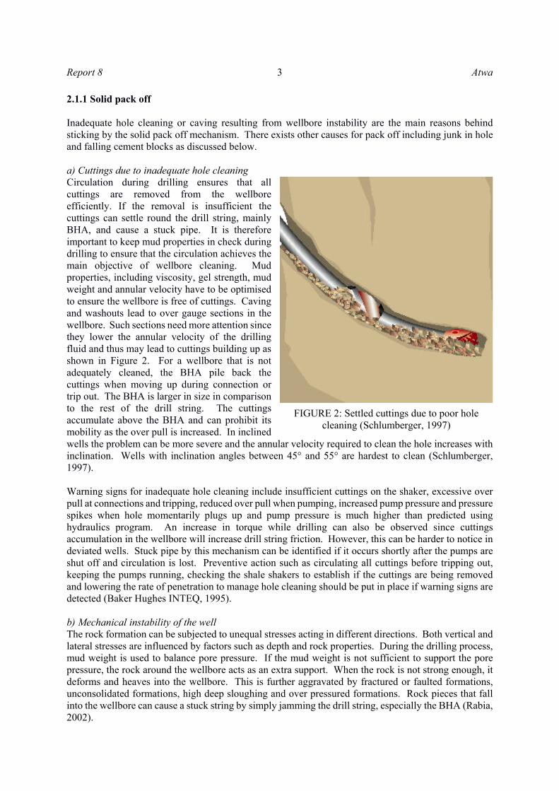
2.1.1 Solid pack off Inadequate hole cleaning or caving resulting from wellbore instability are the main reasons behind sticking by the solid pack off mechanism. There exists other causes for pack off including junk in hole and falling cement blocks as discussed below. a) Cuttings due to inadequate hole cleaning Circulation during drilling ensures that all cuttings are removed from the wellbore efficiently. If the removal is insufficient the cuttings can settle round the drill string, mainly BHA, and cause a stuck pipe. It is therefore important to keep mud properties in check during drilling to ensure that the circulation achieves the main objective of wellbore cleaning. Mud properties, including viscosity, gel strength, mud weight and annular velocity have to be optimised to ensure the wellbore is free of cuttings. Caving and washouts lead to over gauge sections in the wellbore. Such sections need more attention since they lower the annular velocity of the drilling fluid and thus may lead to cuttings building up as shown in Figure 2. For a wellbore that is not adequately cleaned, the BHA pile back the cuttings when moving up during connection or trip out. The BHA is larger in size in comparison to the rest of the drill string. The cuttings accumulate above the BHA and can prohibit its mobility as the over pull is increased. In inclined wells the problem can be more severe and the annular velocity required to clean the hole increases with inclination. Wells with inclination angles between 45° and 55° are hardest to clean (Schlumberger, 1997). Warning signs for inadequate hole cleaning include insufficient cuttings on the shaker, excessive over pull at connections and tripping, reduced over pull when pumping, increased pump pressure and pressure spikes when hole momentarily plugs up and pump pressure is much higher than predicted using hydraulics program. An increase in torque while drilling can also be observed since cuttings accumulation in the wellbore will increase drill string friction. However, this can be harder to notice in deviated wells. Stuck pipe by this mechanism can be identified if it occurs shortly after the pumps are shut off and circulation is lost. Preventive action such as circulating all cuttings before tripping out, keeping the pumps running, checking the shale shakers to establish if the cuttings are being removed and lowering the rate of penetration to manage hole cleaning should be put in place if warning signs are detected (Baker Hughes INTEQ, 1995). b) Mechanical instability of the well The rock formation can be subjected to unequal stresses acting in different directions. Both vertical and lateral stresses are influenced by factors such as depth and rock properties. During the drilling process, mud weight is used to balance pore pressure. If the mud weight is not sufficient to support the pore pressure, the rock around the wellbore acts as an extra support. When the rock is not strong enough, it deforms and heaves into the wellbore. This is further aggravated by fractured or faulted formations, unconsolidated formations, high deep sloughing and over pressured formations. Rock pieces that fall into the wellbore can cause a stuck string by simply jamming the drill string, especially the BHA (Rabia, 2002).
FIGURE 2: Settled cuttings due to poor hole cleaning (Schlumberger, 1997)

Atwa 4 Report 8
Warning signs for such caving include large cuttings with low shale strength, tight hole over long sections during trips, large over pulls, increase in pump pressure due to increase in annular volume and lower drilling rate. To prevent stuck pipe, the mud weight should be gradually increased, the rate of penetration lowered and the wellbore cleaned thoroughly. Each section of the wellbore should be completed as fast as possible to minimize time in hole. c) Falling cement blocks Cement blocks result from open hole squeeze plugs, unstable hard cement around the casing shoe from the rat hole and kick off plugs. While drilling the subsequent sections, unstable cement blocks may fall into the wellbore and jam the BHA. Warning signs for falling cement blocks include cement fragments in the circulation returns and erratic torque. Unrestricted circulation, rotation and downward movement may be possible. To prevent this it is important to always maintain the circulation and jar the string in the opposite direction of the initial movement as first action. This problem can be prevented by limiting the casing rat hole length to minimize source of cement blocks. Sufficient curing time should be allowed for cement before attempting to kick off or drill out. The casing shoe and the hole plugs sections should be reamed thoroughly before resuming drilling and trip speed should be slowed down with bit, stabilizers and mud motor entering the casing shoe or the plug depth. d) Falling junk In the process of drilling, debris or tools may fall into the hole from the surface or from down hole equipment. This may lead to jamming of the string resulting in a stuck pipe. Poor housekeeping at the rig floor, an uncovered open hole and down hole equipment failures are the main causes for this problem. Indicators of junk in the hole are the inability to deepen the hole, sudden erratic torque, metal shavings at the shaker, unrestricted circulation, missing hand tools and equipment as well as repair and maintenance works recently performed on the rig floor. To free the string, the circulation has to be maintained and the string jarred in the opposite direction to the direction it was moving to before getting stuck. Good housekeeping at the rig floor and regular inspection of the handling tools should always be encouraged. All down hole tools should be inspected before running in the hole. The drill string wiper should be installed as quickly as possible and the hole should be covered at all times. 2.1.2 Wellbore geometry Sticking by wellbore geometry occurs due to a mismatch between the BHA size and the size of the wellbore previously drilled. The wellbore may have been drilled under gauge or constricted by other factors like swelling clays and mobile formations. The main causes are discussed below. a) Key seat Rubbing of the drill pipe against the wall of the wellbore may lead to the forming of a groove (key seat) depending on the formation strength and the force with which the pipe is rubbing. These high side forces and rotation facilitate the formation of a groove of about the same diameter as the tool joints. When pulling out of the hole, the BHA may be pulled into the groove which may be too small for it to pass. This will cause jamming and subsequent stuck pipe. The problem is mainly experienced in deviated wells where an abrupt change in angle or direction in medium soft to medium hard formation aggravates the problem. Indications include sudden over pull as the BHA reaches the dogleg section when being pulling out of the hole. Circulation is unrestricted circulation and the string may move freely below the key seat depth if not already stuck in the key seat. Cyclic over pull at tool joint interval may also be experienced. Jarring down with maximum trip load before reaming back out of the hole can free the stuck pipe. To prevent stuck pipe by this mechanism, avoid drilling for long hours with no wiper trips through the
Report 8 5 Atwa
dogleg sections, minimize dogleg severity and consider running string reamers or key seat wipers if a key seat is likely to cause a problem. b) Mobile formations Salt or wet shale may flow into the wellbore and bridge off the annulus causing the drill string to be stuck. The overburden stress from the overlying rock squeezes the salt out into the wellbore. Chemically active formations react with drilling fluids and swell as they protrude into the wellbore. All these processes can limit the mobility of the drill string and accumulate in sufficient quantities to fill the entire annulus round the BHA causing a stuck pipe. The warning signs include large over pulls at the connections, increased pump pressure, increased mud chlorides and clumps of hydrated shale from the hole. An increase in torque and reduction in drilling rate may be experienced. Circulation is restricted or completely blocked depending on the severity of the clay flow. To prevent sticking from this mechanism, time in open hole should be minimized as well as the length of the BHA and open hole sections. Mud inhibitors and stabilizers should be pumped to reduce the swelling effect to the clays. Open wireline logging prior to the running of the casing should be minimal or skipped entirely. c) Under gauge hole Bits and stabilizers are normally worn out with continuous usage especially while drilling abrasive rock. The reduced bit and stabilizer gauge result in a relatively smaller gauge hole. When a in-gauge bit is run, it encounters resistance due to the small gauge of the hole. The bit can jam in the under gauge section of the hole especially if it is run into the hole fast without reaming. This may occur after running a new bit, after coring, when a PDC bit is run after a roller cone bit or when drilling abrasive formations. Core heads are often slightly smaller than bit sizes and cored sections should be reamed well when running in with a bit to drill ahead. To prevent this the usage of suitable gauge-protected bits, stabilizers and roller reamers is recommended. Always gauge BHA components both when running in and pulling out of the well. Slow the tripping speed before the BHA enters the under gauge hole. Stuck pipe by under gauge hole occurs only while running in hole. Bit will normally stick near the bottom of the hole or at the top of the cored section. To unstick the string, the first action would be to jar up with maximum trip load. d) Micro doglegs and ledges Doglegs are sharp deviation in wellbore trajectory often developed when the characteristics of a rock cause the bit to be deflected and change direction. Doglegs are more severe while drilling directional wells, where sudden changes in angle can cause an irregular trajectory in the wellbore (Kahutu, 2016). Ledges form when drilling through intermittent hard and soft layers of rock with different washout rates. Sticking by this mechanism occurs while tripping out of hole as the BHA runs into the ledges and doglegs in the hard-soft interbedded formations. Running in hole with a packed hole assembly will reduce ledges as well as minimize direction changes in the wellbore. Changes in BHA configurations are likely to produce ledges and hence should be minimized. Trip speeds should be slowed down when the BHA enters the suspected ledge zone or dogleg. Prolonged circulation across the soft interbedded formations can aggravate the formation of ledges through washouts. To free a stuck pipe from ledges, apply torque and jar down with maximum trip load assuming the string was moving up before sticking occurred. Back ream or ream very slowly past problem area as rotation will assist the stabilizers to roll past the ledge. e) Drilling into green cement Running the drill string into wet cement will cause the cement to flash set due to increase in pressure generated by the surge. With the string bottom in the wet cement, circulation will increase the pressure, which in turn causes the cement to set further. Sticking will only occur when tripping in hole (lowering the drill string into the hole) to drill out cement (Awili, 2014).

Atwa 6 Report 8
The main indications for a stuck pipe by this mechanism are an increase in pump pressure leading to inability to circulate, loss of string weight, a sudden increase in torque and green cement in mud returns. To prevent drilling into wet cement, it is important to keenly monitor surface samples, to know the setting time from laboratory tests and give the cement enough time to set. Calculated the depth of the top of the cement before tripping into the hole but always expect it to be higher. Begin washing down two stands above the theoretical top of cement depth in large hole sizes and four stands above for small hole sizes. f) Drilling into magma Magma intrusions can exist at shallow depths in some drilling fields. When drilling into these intrusions they are rapidly cooled by the drilling fluid, producing glassy cuttings. Sticking problems will occur when this rapid cooling of the magma happens just above the bit and retrieval of the BHA becomes a problem. The Icelandic Deep Drilling Project well 1 was halted after having reached magma. The well was side-tracked twice and in the third attempt, anticipation of the conditions to be encountered and proper reaction kept the string from being stuck (Hólmgeirsson et al., 2010). Monitoring drilling parameters keenly and analysing the drilling information of the adjacent wells can go a long way to manage this problem. In general, Baker Hughes INTEQ (1995) summarizes mechanical sticking problems and indicators as shown in Table 2:
TABLE 2: Mechanical sticking problems and indicators (Baker Hughes INTEQ, 1995)
Problem Torque Pressure Drill rate Poor hole cleaning Increase Increase Gradual increase High overbalance Gradual increase No change Gradual decrease Mobile formations Gradual increase Increase Gradual decrease Fractured and faulted formations
Sudden erratic increase
May be unaffected Sudden increase
Geo-pressured formations Increase Increase Initial increase then gradual
decrease Reactive formations Gradual increase Increase Gradual decrease Unconsolidated formations Increase Increase Decrease Junk Sudden increase No change Sudden decrease Cement blocks Sudden increase No change Sudden decrease
2.2 Differential sticking Differential sticking occurs when the drill string is held against the wellbore while sinking into mud cake. It is due to higher pressure in the drilling mud than the formation. Formation pressure acts on the area of the drill collar embedded into the mud cake while the hydrostatic pressure in the drilling mud acts on the area of the drill collar that is not embedded in it. Whenever hydrostatic pressure in the wellbore is higher than the formation pressure, there will be a net force pushing the collar towards the bore hole wall (Baker Hughes INTEQ, 1995). Differential sticking will occur in following these conditions:
Stationary or very slowly moving drill string; Existence of conduct between the drill string and the wellbore; Hydrostatic pressure being higher than the formation pressure; Existence of a permeable formation; and Presence of a thick filter cake.

Report 8 7 Atwa
Ideally, mud cakes should be thin, hard and made up of mud solids only. Thick filter cakes act as a barrier to stop further seeping of mud filtrate into the formation as illustrated in Figure 3. Stationary or slowly moving drill pipes encourage filter cake to build around it and subsequently add to the differential sticking force holding the collars. Warning signs for differential sticking include increasing over pull and drag in long connections, increase in over pull and torque after the drill string has been stationary for some time and decrease in over pull after reaming. Loss of mud while drilling permeable zones and constant movement of drilling fluids may indicate a differentially stuck pipe, which cannot be moved up or downwards and cannot be rotated. According to Baker Hughes INTEQ (1995), if differential sticking occurs the initial actions will be:
Circulate at maximum allowable rate in attempt to erode the filter cake; Apply maximum limit right-hand torque to the stuck depth and slump if the bit is off bottom or
pull to the maximum immediately and jar; Stop or reduce pumping rates to the minimum; Slack off to maximum set-down limit; Allow sufficient time for a hydraulic jar to trip; and If the string does not come loose, maintain the torques in the string and continue jarring with
maximum trip loads. Secondary actions include reduction of hydrostatic mud pressure in the annulus, oil spotting around the stuck portion of the drill string and washing over the stuck pipe. Hydrostatic pressure in the annulus can be reduced by diluting the mud to reduce its weight, gasifying with nitrogen gas or placing a packer in the hole above the stuck point. After freeing the string, it should be rotated and worked while circulation is at maximum rate to clean the hole. Mud specifications should be checked at this point to prevent reoccurrence of the problem. According to Baker Hughes INTEQ (1995), over pull due to differential sticking can be calculated from the product of differential pressure force multiplied by the friction factor as follows:
𝑝𝑢𝑙𝑙 𝐹 𝑓 (1)
where 𝐹 = Differential pressure force (psi/in2); and 𝑓 = Friction factor of the drilling fluid. The cross-sectional area is used to calculate the force but not the surface area of the drill collar, therefore the differential pressure force, 𝐹 , is defined as:
FIGURE 3: Differential pressure sticking (SPE, 2007)

Atwa 8 Report 8
𝐹
144𝑓𝑡
∗ 𝐴 𝑃 𝑃 (2)
where: 𝐹 = Differential pressure force (lbf); 𝐴 = Cross-section embedded in mud cake (𝑓𝑡 ); 𝑃 = Hydrostatic pressure (psi); and 𝑃 = Formation pressure (psi) The friction factor depends on the formation and the drill collar surface. It varies from 0.15 to 0.50. The hydrostatic pressure 𝑃 is defined as:
𝑃 𝑇𝑉𝐷 ∗ ɣ
𝑇𝑉𝐷 ∗ 𝜌 ∗ 0.433𝑝𝑠𝑖 𝑓𝑡⁄
8.33𝑝𝑝𝑔 (3)
where: 𝑃 = Hydrostatic pressure (psi); 𝑇𝑉𝐷 = True vertical depth (ft); ɣ = Pressure gradient of the mud (psi/ft); and 𝜌 = Mud weight (ppg) Note: Fresh water has a density of 8.33 ppg and a pressure gradient of 0.433 psi/ft. 3. FISHING Tubulars or any other materials like bit cones and junk may get stuck in the well preventing further well development programs like drilling, casing or completion of operations. Any action to release, remove or recover such tubulars and any other materials in the well is known as fishing. Fishing is a remedial activity and should be avoided at all cost since it reduces the drilling efficiency and increases the drilling costs. For successful fishing operations, competency in drilling and fishing operations is key. A good channel of communication and a clear chain of command can help to achieve good decision making. The general rules that apply to fishing jobs include careful planning and decision making, good preparation and the knowledge of fishing operations and equipment at disposal. Knowing when to quit a fishing operation can help to minimize time wastage and costs. The drilling crew should be aware of the fact that sometimes fishing operations have to be terminated before they are completed. The alternative to well abandonment is normally to plug the hole and re-drill or plug back and side-track. Fishing operations should be suspended when the total cost of fishing operations has reached approximately one half of the total well cost when fishing operation began. For deeper wells which may be plugged and side tracked, fishing operations should be suspended when the estimated cost to recover the fish is about the same as the estimated cost to plug back, side track and re-drill the hole to the original depth where the fishing job started (Short, 1981). 3.1 Free point determination It happens sometimes that after all measures have been put in place, the drill string is still stuck. The force required to pull the string free should not exceed the yield point of the weakest member in the drill string, otherwise the string will shear off complicating the fishing operations further. At this point remedial measures like parting the string or spotting lubricating fluid around the stuck point are taken. It is very important to establish the location of the stuck pipe. According to Baker Hughes INTEQ (1995), the following procedure can be used to pinpoint the stuck point as illustrated in Figure 4.

Report 8 9 Atwa
An upward force F1 is applied to the pipe. This force must be greater than the total string weight in air to ensure that the string is under tension;
A reference point is marked on the drill pipe at the surface, normally at the top of rotary the table;
A greater upwards force, F2, is applied causing the free point of the drill string to stretch by the amount e. The stretch is measured above the reference point.
The equation below is then applied to establish the stuck point:
𝑆𝑃𝐿 735 10w e𝐹2 𝐹1
(4)
where 𝑆𝑃𝐿 = Stuck pipe location; 735𝑥10 = Derivation of Young´s Modulus for steel; 𝑤 = Weight of the drill pipe (lb\ft) e = Length of the stretch;
F1 = Force applied when pipe is in tension (lb); and F2 = Force applied to stretch the pipe by length e (lb).
The location established by this equation is not the exact point since it does not take friction between borehole and the drill pipe into account and in the case of a deviated well, it is very difficult to tension the drill string and not having it to come into contact with the formation. The
stretch measurement does not account for the drill collars and heavy weight drill pipes response to the pull. However, this method is simple and provides a rough estimate of the stuck point before running a free point indicator into the hole. The location of the stuck point can also be established by the use of a free point indicator tool as shown in Figure 5. This tool is lowered inside the string to determine the stuck point more accurately before performing other procedures like parting the string. The tool is designed to determine the stuck point by locating points in the drill string with zero tension and/or zero torque when the string is torqued and/or tensioned. The tool also establishes the degree of the blocking which ranges from totally stuck (0% free) to totally free (100% free). Deviated wells gives less accurate torque and over pull measurements due to friction. Back off attempts are done on the next connection above the free connection and the string should be 80-90% free of torque and tension at this point (Short, 1981).
FIGURE 4: Free point tool (Short, 1981)
FIGURE 5: Stuck point determination (Baker
Hughes INTEQ, 1995)

Atwa 10 Report 8
3.2 Types of fish The main objective of a drilling operator is to drill and complete a producing well. Any stuck material in the well may prevent this objective from being achieved. Fish come in different sizes and shapes and therefore there is a big variance in fishing operations. Fish can be classified into the categories described below (Short, 1981). 3.2.1 Small objects such as bits and cones It is common for small pieces of junk to be left in the hole. These include bits, bit cones, millings and wall off junk. These are normally recovered by the use of either a magnet for magnetic materials or by a junk basket. Depending on the formation, these pieces may be milled and circulated in a junk basket or walled off. 3.2.2 Drilling assemblies A drill string and other downhole assemblies may be stuck in the well due to various reasons including pack off through caving and sloughing, trapping in a key seat, differential sticking or other causes. Working the string up and down, over pull, jarring and reaming may be employed to free the stuck string. Parting and retrieving the part of the string that is free by the use of explosives or by back off may enable the lower part of the fish to be washed over and therefore enable its retrieval. 3.2.3 Test tools packers and plugs It is often common for the test tools, packers and plugs to be accidentally left in a wellbore preventing further development of the well. Many packers and plugs are made up of drillable material so that they can be drilled out without any excessive difficulty. Test tools are usually run under jars to permit jarring on the tool if it becomes stuck. Considering the size and depth of the hole, milling comes in handy when running small wireline tools at depths. 3.2.4 Wire lines and wire line tools Wireline and wireline tools may be stuck while conducting well testing. Some of these tools may hinder further development of the well or be expensive thus making their retrieval a necessity. Magnets may be run to retrieve light magnetic objects, however, grabs and wireline spear which have prongs fitted with barbs are normally used in this case. Over shots have also been employed to recover wireline tool fish. 3.2.5 Small diameter tubulars These are small tubing strings run in cased holes. The smaller tubulars have limited strength and may be subject to failure in tension. Complexity and difficulty of the fishing operation will increase with decreasing tubing size. The failure will normally occur when the well is producing, or when a major part of the expenditure has already been incurred during the drilling. Due to their sizes, these tubings pose a special problem for fishing. Because they are run in a cased hole, there is limited clearance making it difficult to fish. Whenever possible, washing over and retrieval of the fish by use of an overshot is carried out. Small tubings are flexible and have low structural and tensile strength making it complicated to fish. Use of concentric tubing make fishing jobs less complicated especially if smaller strings can be retrieved by pulling out the bigger tubing. 3.2.6 Assemblies bent or parted above the rotary Occasionally, the drill string may fail above the rotary table resulting in the string falling down into the well. The failure may be a bent or parted pipe, however, correct equipment and operating technique will

Report 8 11 Atwa
help prevent the string from dropping and causing a fishing job. Caution should be taken when picking up a severely bent pipe as failure may result from the fatigue material, leading to parting and subsequent dropping into the well. The best action for handling a severely bent pipe would be an arrangement to catch or hold it at a point below the bent section to prevent it from dropping down hole. Slips may be installed to catch a pipe that parts at the bend. 3.3 Fishing tools Familiarity with various fishing tools and selection of the most suited one for a particular application is what successful fishing operators are known for. Size, weight and depth of the fish dictates the type of fishing tool to employ. With increasing depth of the fish in the well, the number of available fishing tools decreases. Fishing operations may become necessary in both cased or open holes. Fishing tools can be categorized by the item on which they can be run: tubulars, wireline, both or fishing assembly (Short, 1981). 3.3.1 Tubular fishing tools These are types of fishing tools designed to be run on tubulars like drill pipes and collars. During fishing operations, they are operated by reciprocating motion, rotation or both. They include mills, over shots, junk baskets, wash over pipes, casing spears, taper taps, die collars, knuckle joints, bent subs, wall hooks, jars, bumper subs, junk subs, circulating subs and safety joints. 3.3.2 Tubular or wireline fishing tools These are fishing tools that can be run on either tubular or wirelines. The way in which the tool is run and operated differs depending on the item on which it is run. Such tools are selected depending on the stage of well development. They include rod sockets, wireline spears, wireline grabs, magnets, impression blocks, junk shots, junk catchers, chemicals and jet cutters. 3.3.3 Wireline fishing tools These tools normally operate by reciprocating motion. Their efficiency decreases with increasing depth due to the increased weight while is also becomes more difficult for the operator to determine the specific tool action. Wire lines exist in many sizes and configurations and these characteristics dictates their specific use. Fishing tools run on wireline include the wireline overshot, blind box, sinker bars and the bailer. 3.3.4 Fishing assembly A fishing string is a complete downhole assembly that is designed for a fishing job. Due to extra wire strength needed for this operation, connections are normally minimized. Special pipes may be preferred over the tubing used in other operations. Worn out or slightly under gauge drill pipes may compromise the fishing job. The tubing can be fitted with screws in the tool joint to minimize joint damage. It is advisable to be thoroughly familiar with the fishing tool and its operation before considering using it. More information can also be sought from the tool manufacturer. 3.4 Fishing methods These are basic operational procedures when a fishing job arises. All these methods aim at releasing the stuck pipe with as little cost as possible. It is upon the operator to decide the best course of action depending on the prevailing conditions of the stuck string (Short, 1981).
Atwa 12 Report 8
3.4.1 Milling, drilling and walling off Small pieces of junk in the hole like bit cones may prevent further drilling operations to take place. These pieces are normally milled, retrieved or walled off depending on the formation and the size of the junk. Small and softer junk can be drilled on using the bit which can also wall them off by pushing and burying them in the wall of soft or medium formation. Mills are normally used to get rid of tougher junk in the hole. The milling operation is rough and thus caution should be taken not to leave more junk in the hole. In other cases, the junk may not be firmly held and will tend to rotate with the milling reducing the milling effect. This can be solved by conducting a plug job before milling ahead. Mills can also be used to dress top of the fish before other operations take place. Depending on how the string parted, the top of the fish could be bent, twisted or broken and dressing it off will facilitate a clean top to the fishing tool before it can be caught or recovered. 3.4.2 Working stuck downhole assemblies Most fishing jobs begin when the down hole assembly gets stuck and the common fishing procedure is to immediately work the down hole assembly and try to release it. Working the drilling assembly involves moving it up and down (reciprocating), rotating and circulating to release all or part of the assembly. This procedure not only completes the fishing job but also is important for preventing stuck pipe events. Stuck assemblies should be worked up immediately and constantly to prevent accumulation of materials and wall sticking. The stuck string is worked based on various indicators of stuck pipe mechanisms. As long as there is either axial movement, rotation or circulation, there is a chance the assembly can be manipulated to perform other functions. 3.4.3 Releasing fluids These fluids can be circulated downhole to the point of stuck pipe to help release the assembly. Fluids and additives may have properties that can increase lubricity or help prevent sticking of the assembly. Most of these fluids are used in open holes. To free a string stuck by differential sticking, releasing fluids are pumped while working it simultaneously to establish motion. These fluids can be used at different stages of the working cycle. Soaking agents can help release assemblies that are wall stuck. Friction reduction agents such as oil and graphite increase lubricity. These are applied where there is increased or excessive drag when the down hole assembly is moved. Dissolving agents come in handy when the downhole assembly is stuck in a formation that is soluble. Salt formations which are drilled with salt saturated fluids or oil muds can be washed by circulating fresh water whenever they cause a stuck pipe. 3.4.4 Parting pipes In some cases, working the stuck string does not free it and continuing with the fishing activity engages more time and resources. The following step can involve the parting of the pipe and pulling out the free end before running in with a fishing assembly to recover the fish. Working the string for too long deteriorates the hole condition and increases the probability of failure that may result into more severe fishing jobs. Under normal conditions, the stuck drill string should not be worked less than six and no longer than twenty-four hours (Short, 1981). For a short catch overshot to catch the pipe body or a long catch overshot to catch the tool joint or collar, the string is usually parted three feet above the tool joint or collar. Parting should be performed in an in-gauge, straight hole section. Depending on the downhole equipment and conditions, different methods are used to part the drill assembly. These include backing off or cutting (mechanical, chemical or jet). When backing off, the free point is first determined by either running a free point indicator in hole or by calculation. The left-hand torque is then applied while working the string. A string shot is then run and positioned opposite of the joint to be backed off and detonated. The pipe is then pulled out of the hole to conduct a fishing operation. In other cases, cutting the string by chemicals, jets or
Report 8 13 Atwa
mechanically may be preferred. Chemical and jet cutters are run on wirelines. Mechanical tools are run either on drill pipes or tubing. Mechanical wireline cutters can be used to part pipes and HWDP. No explosives are required for this case. Handling and transporting of explosives is becoming more restricted all over the world due to rules and regulations. 3.4.5 Catching the fish Catching the fish during fishing operation means holding onto the fish with a force that will enable the whole assembly to be worked and retrieved from the hole. It involves selection of the method to catch the fish, tools to be used and the auxiliary equipment. Methods of taking hold of a fish are swallowing, screwing in, inside catch and outside catch. A method that gives the strongest connection between the fish and the fishing string should be selected. 3.4.6 Cleaning inside the fish The fish must be open to perform operations inside such as running a free point tool, backing off and perforating for circulation. These operations enable the fish to be caught and to be connected to the fishing assembly. It may be necessary to mill or cut a clean top of the fish to let tools pass through the fish top. If the lower part of the string is open and free to circulate, cutting bridges can be removed by pumping them out. String shots or junk shots (explosives) can also be used to remove accumulated cuttings in case of a fish that is caught with screws in connections. 3.4.7 Washing over the fish A fish can be stuck in such a way that it cannot be jarred or worked loose. In this case, washing over the fish could be the best solution. For a long section of stuck fish, the fish can be washed over in parts and one section recovered before continuing. Wash over pipes need to be of a larger internal diameter to accommodate the fish and an outside diameter small enough that it can be run safely in a hole. A wash over shoe is normally connected at the bottom of the wash over pipes and comes in different designs depending on the objective to be achieved. Shoes can range from a long tooth design for soft formation to complete mill shoe for cutting metals. After washing over, the fishing assembly is then run into hole to recover all or part of the string. Care should be taken while washing around the fish in a cased hole as this may result in mechanical sticking. 3.4.8 Perforating to circulate and release the fish Circulating through a stuck string assembly eases the release and recovery of the assembly. Reciprocating motion seeks to establish circulation and free the stuck pipe. When the drill assembly is stuck and cannot be circulated due to bridging by cuttings and caving around the string, freeing it can be difficult. To establish circulation, one or two perforations are made in the stuck string and pressure is applied progressively as the string is worked. Other procedures include pumping the string from the hole and side tracking while fishing. It is worth noting that several problems can adversely affect fishing operations including both downhole and surface equipment. Only those who are familiar with specific problems and fishing operations in general should be making the necessary decisions. 4. STUCK PIPE ANALYSIS IN OLKARIA GEOTHERMAL FIELDS, KENYA Stuck pipe incidences have been a frequent occurrence during drilling in Olkaria geothermal field. In this field, the main causes of stuck pipe are geological challenges, surface equipment malfunction and down hole equipment failures. A list of five wells distributed all over Olkaria geothermal field is shown in Table 3. The wells were drilled within the last four years.

Atwa 14 Report 8
TABLE 3: Recent stuck pipe incidences in Olkaria field
Well Olkaria
Field
MD of sticking
(m)
Activity at sticking
Hours End result Total days
for well MD (m)
OW-45 East 354 DOC 2 Freed
113 764 629 WOR 2 Freed 764 POOH 1200 Abandoned
OW-53D East 568 Drilling 60 Freed
92 3000871 Drilling 212 Freed
OW-205 Central 108 Drilling 6 Freed
90 3010305 POOH 18 Freed 2954 Tripping in 87 Freed
OW-807B Southeast 204 Connection 10 Freed
82 291 290 Drilling 1800 Abandoned
OW-905B Domes 811 Drilling 29 Freed
135 829 829 Drilling 1680 Abandoned
Much time and resources have been spent on fishing operations, some of which were not successful. With the daily rig rate at KenGen ranging between USD 25,000 and USD 30,000 (KenGen, 2015), it means millions of dollars have been spent on these operations yielding minimum success. Detailed analysis for each of the listed well is carried out to establish the real cause of the stuck pipe, the best fishing method and how to prevent this situation all together. 4.1 Well OW-807B Figure 6 shows the planned and the actual drilling progress (depth against number of days) for well OW-807B. 4.1.1 Background and sticking analysis for OW-807B The well is located in the south east of Olkaria geothermal field. Being a directional well, the well was supposed to be top holed by a smaller rig N370 to 300 m RKB before being drilled to completion by 2000HP rig KGN2. The well was supposed to provide steam for the proposed Olkaria VI power plant. It was spud in on 7th November 2017 and a 26" diameter hole was drilled with water based viscous mud to 62.3 m RKB with circulation returns being received at the surface. 20" casings were run and cemented in place. When the cement had dried, a slick BHA was run to drill out the excess cement using water to 88 m RKB where the slick BHA was replaced with the pendulum BHA. The 17½" diameter hole was drilled to 204 m RKB where the pipe got stuck. The string could be freed after introducing aerated water and foam to unload the wellbore. Reaching 290 m, the string got stuck again and could not be freed despite attempts being made. While drilling the anchor section of the well, there were frequent breakdowns of the surface equipment. Repairs on the riser system, shale shaker motor, replacement of the shale shaker screens and clutch plates took about 10 hours and these may have resulted into more problems down hole. After the first stuck pipe incidence, rigging up of the air package system took four hours. The upper section of the hole was in a zone of unconsolidated pyroclastic materials consisting of pumice, tuff, volcanic ash and lithic rock fragments in which cave-ins were expected. Rhyolites, tuffs and minor basalts formed the intermediate zone between 140 m and 300 m depth. The soft formation contains pieces of hard blocks. Circulation losses were also expected in this region. The drilling parameters and rock types are shown in Table 4.

Report 8 15 Atwa
TABLE 4: Drilling parameters and rock types, well OW-807B
MD (m RKB)
Drilling fluid parameters
Average ROP (m/h)
Torque (ftlbs)
Circulation (l/m)
Rock type Other comment
0-62 Viscous mud with returns on surface
3.3 7000 1600 Pyroclastic 26" diameter hole
63-88 Viscous mud with returns on surface
6.5 7500 1800 Pyroclastic 17½" diameter hole using slick BHA
89-204 Viscous mud but lost circulation returns at 200m
3.7 7000 2100 Pyroclastic and rhyolite
Got stuck at 204 m making a connection, switched to aerated air and foam to free the string.
205-290 Aerated water and foam with circulation returns
5.4 7000 2700 Rhyolite, tuffs
and minor basalt
Got stuck at 290 m while drilling and lost circulation after that.
FIGURE 6: Well OW-807B drilling progress (KenGen, 2018)

Atwa 16 Report 8
The first incidence of a stuck pipe (at 204 m) occurred while a connection was made. Given that there were no circulation returns and the formation was unconsolidated, possible causes of the stuck pipe are summarized in Table 5:
TABLE 5: Causes of stuck pipe in well OW-807B
MD (m
RKB)
Changes in torque
Changes in WOB
Changes in ROP
Circulation returns
Stuck pipe indication
Possible cause of stuck pipe
204 During
connection During
connection During
connection
No returns until air package was
introduced
Drag on pulling
Pack-off caused by poor hole cleaning. Cuttings settled during connection packing off the BHA.
290 Increase Unchanged Unchanged
There were circulation
returns but were lost after the stuck pipe incidence
Increase in torque which slowed down
RPM to 0
The unconsolidated formation could have resulted in cave-in and subsequently solid pack off.
The soft formation, a relatively high rate of penetration and lack of circulation returns could have resulted into cuttings build up in the wellbore. This could have been worsened by rocky boulders caving in the wellbore as the drilling operations were interrupted to attend to surface equipment. At the first incidence of a stuck pipe at 204 m, air package and foam was introduced. After some time of circulation, cuttings were received at the surface before the string was unstuck. Before this point there was no increase in stand pipe pressure yet the returns were not received at the surface. This indicated that the circulation fluids were being lost in the formation. An increase in pumping rate could increase the wash out of the unconsolidated formation and subsequently increase the pack-off. 4.1.2 String freeing and fishing attempts The attempts to free the stuck pipe are listed in Table 6:
TABLE 6: Well OW-807B string freeing and fishing attempts
No. Activity Time (days)
Response
1 Working the string up and down. The operation had to be stopped to repair the clutch.
2 None
2 Pumping lubricating fluids including pipe lax and diesel. At this point circulation was not possible as returns were not received at the surface after circulating with aerated water and foam.
Continuous None
3
Backing off and running wash over pipes in hole to clean around the fish. This was possible up to the string stabilizer which was located 12 m above the bit. POOH and RIH with drill string to latch on fish, freeing attempt was not successful.
4 None
4 RIH with 3½" drill string in the annulus to try and wash beyond the stabilizer and attempt to back off using the left hand drill string with no success.
4 None
5 RIH with overshot and jar, latched onto the fish and jarred. A movement of 0.5 m was attained but the string could not be released.
5 0.5 m
movement of fish

Report 8 17 Atwa
No. Activity Time (days)
Response
6 With over pulls of up to 70 tons the string was unstuck but after pulling out 20 m of the string, it got stuck again.
6 20 m of fish movement
7 Working the string up and down while circulating using aerated water and air with returns being received on surface.
8 Fish
completely released
8
On running in hole, an obstruction was realised at the depth of 235 m. A magnet was run in hole but did not retrieve anything. An impression was run and it indicated an irregular object in the well. Then a milling tool and junk basket were run but could not go beyond this point.
6
9
The well was plugged on several attempts since it was difficult to reach the target plug depth of 180 m. Attempts to side-track were futile, as the side tracking BHA could not go beyond the suspected fish zone of 254 m. The decision was made to abandon the well.
23
Circulation returns were lost immediately after the sticking problem occurred. This could have possibly resulted from caving-in of the wel bore from unconsolidated formation. Picking up the string immediately could have compressed the cuttings or debris between the BHA and the walls of the hole. 4.2 Well OW-45 Figure 7 shows the planned and the actual drilling progress (depth against number of days) for well OW-45. 4.2.1 Background and sticking analysis for OW-45 The well is located in the Olkaria East production field. It was designed to be drilled vertical to a total depth of 3000 m. Rig N370 was supposed to top hole the well to 300 m before being drilled to total depth by Rig KGN2. Well OW-45 was planned to be used for deep re-injection to recharge the Olkaria East production field reservoir. The well was spud on 28th September 2014. A 26" diameter hole was drilled to 15 m RKB with water based viscous mud and circulation returns. From 15 to 62 m the drilling was continued using water with no circulation returns. High viscosity mud sweeps were conducted at connections. Several obstructions were experienced while running the drill string and the 20" casing in hole. The hole was reamed and circulated to clear it of cuttings before successfully running and landing the 20" casing. After cementing the casing and WOC, a slick BHA was run to drill out cement using water to 87 m RKB where the slick BHA was replaced with a pendulum BHA. The 17½" diameter hole was drilled to 305 m RKB. There were frequent cave-ins in this section resulting in more time to circulate and clean the wellbore. Several plug jobs were conducted to stabilize the collapsing formations. The 13⅜" casings were run and cemented in place. The 12¼" diameter hole was drilled using aerated water and foam and circulation returns were received at the surface. On each connection, there cuttings had built up in the wellbore despite thorough cleaning. At 354 m RKB, over pulls were experienced and after concluding that the formation was collapsing, several plug jobs were conducted to stabilize this region. A slick BHA was used to drill out cement using water and thereafter a pendulum BHA was run in to drill ahead on formation using aerated water and foam. Circulation returns were received at the surface. Large columns of cuttings were tagged during connections and because of this, more time was spent on circulation to unload the wellbore. Upon reaching 764 m RKB, the well was circulated then the string was tripped out for bit change. The drill string got stuck while tripping out of the hole at a depth of 734 m RKB. There were drags, over pull and then the string could not be moved up or down nor rotated.
Atwa 18 Report 8
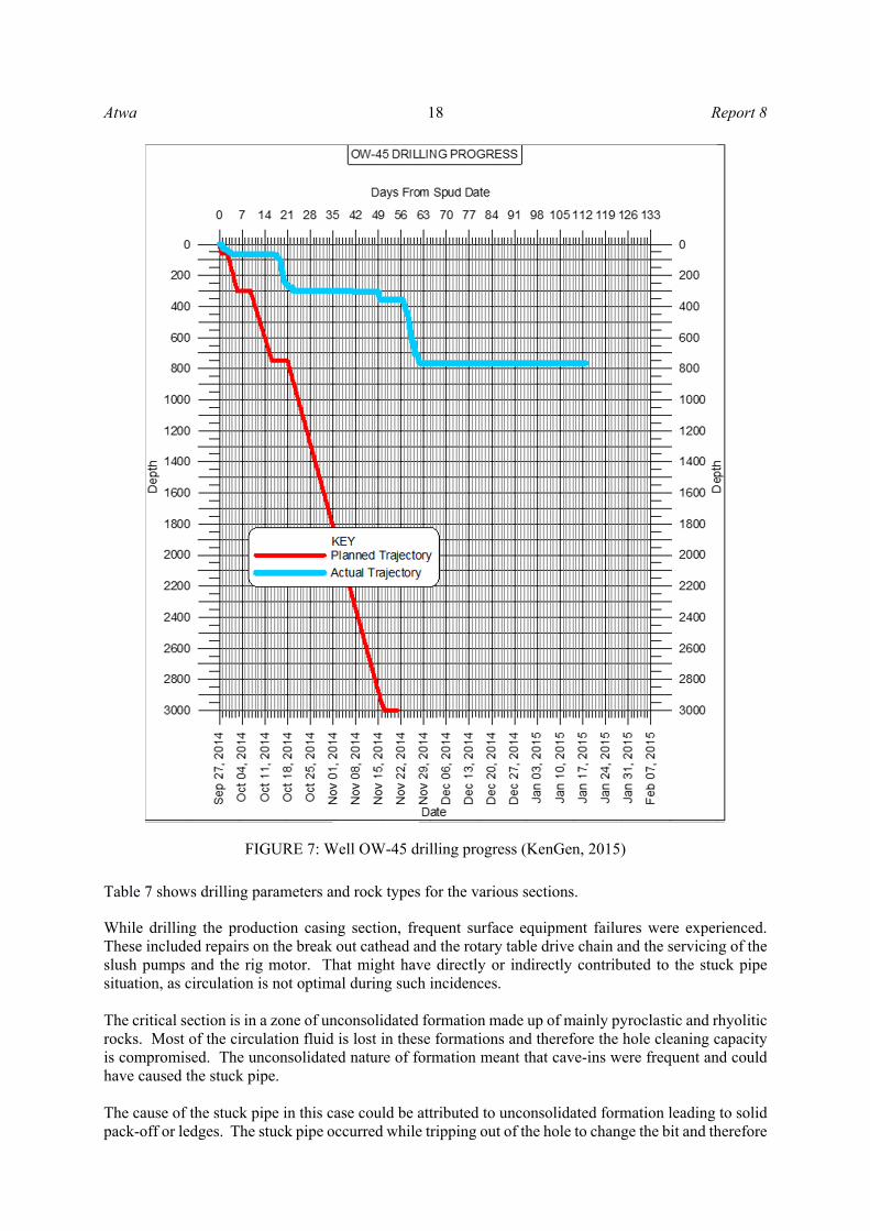
Table 7 shows drilling parameters and rock types for the various sections. While drilling the production casing section, frequent surface equipment failures were experienced. These included repairs on the break out cathead and the rotary table drive chain and the servicing of the slush pumps and the rig motor. That might have directly or indirectly contributed to the stuck pipe situation, as circulation is not optimal during such incidences. The critical section is in a zone of unconsolidated formation made up of mainly pyroclastic and rhyolitic rocks. Most of the circulation fluid is lost in these formations and therefore the hole cleaning capacity is compromised. The unconsolidated nature of formation meant that cave-ins were frequent and could have caused the stuck pipe. The cause of the stuck pipe in this case could be attributed to unconsolidated formation leading to solid pack-off or ledges. The stuck pipe occurred while tripping out of the hole to change the bit and therefore
FIGURE 7: Well OW-45 drilling progress (KenGen, 2015)

Report 8 19 Atwa
the circulation was cut off. This could have caused the settling of cuttings or the cave-in of the soft formation. High trip out speeds could also have led to suction pressure in the wellbore and therefore cave-ins. The alternating formation strength between rhyolites and pyroclastic rock could have led to formation of ledges and consequently caused the stuck pipe while tripping out of the hole.
TABLE 7: Drilling parameters and rock type, well OW-45
MD (m RKB)
Drilling fluid parameters
ROP (m/h)
Torque (ftlbs)
Circulation (l/m)
Rock type Other comment
0-15 Viscous mud
with returns on surface
1.1 7000 1800 Pyroclastic 26" diameter hole
15-62 Water with no
returns on surface
63-87 Viscous mud
with returns on surface
2 7500 1800 Pyroclastic 17½" diameter hole using slick BHA
88-305
Aerated water and foam but
lost circulation returns at 115
m
4.8 7000 2400 Pyroclastic and rhyolite
Collapsing formation and cutting build up during connec-tions were experienced.
305-764
Aerated water and foam with
partial circulation
returns
5 7000 2700 Rhyolite and rhyolitic tuff
Got stuck at 734 m while tripping out to change the bit.
4.2.2 String freeing and fishing attempts Table 8 shows the activities carried out in attempt to fish out and free the stuck pipe. For this particular well, it took a long time to establish circulation through the drill string and this could have worsened the stuck pipe condition. Lack of fishing tools like jars also complicated the matter. Running a 6" bit on 3½" drill string in hole to wash through the annular is not a recommended practice and it resulted in a second fish in the hole. Many days were spent to conduct fishing operation which was not successful in the end. The fishing string was not fit for the job as it kept on snapping at different positions during the fishing operation. Downhole equipment inspection ought to have been done prior to running in hole.

Atwa 20 Report 8
TABLE 8: Well OW-45 string freeing and fishing attempts
No. Activity Time (days)
Response
1 Worked the string up and down while pouring used oil and pipe lax through the annulus.
6
2 Connected back the circulation system and circulated aerated water and foam with no returns at the surface.
2
3 Lifted the well by pumping air in the drill string to pressures of up to 800 PSI and circulation return were received at the surface.
4
4 Backed off at 163 m and RIH with wash over pipes but could not go beyond 163 m due to junk in the hole (stripper rubber), then fished stripper rubber for three days unsuccessfully.
14
5 RIH the 4½" drill string, latched onto the fish and worked it while circulating but without success.
7
6
Backed off inside the BOP, RIH with 6" bit on a 3½" drill string to wash out through the annular to 319 m, the string snapped and 191 m of the 3½" string was left in well. A secondary fishing job became necessary.
3
7 RIH with 4½" open drill pipe, latched onto the initial fish and backed off 73.6 m of the string
6
8 With the last joint partially damaged, a taper tap was RIH and latched onto the fish. When trying to back off, it parted at 82 m
3
9 The 3½" drill string was fished out and the entire length recovered. 2 The 3½" drill
string recovered
10 The 4½" open pipes were RIH, latched on fish and then backed off. 4 14 drill pipes
were recovered.
11 RIH and continued working the string up and down but snapped at 165 m.
6
12 RIH to fish out the snapped pipe using taper tap, but on backing off the string parted just above the taper tap. Then the decision was then made to abandon the well.
22
4.3 Well OW-53D Figure 8 shows the planned and the actual drilling progress (depth against number of days) for well OW-53D. 4.3.1 Background and sticking analysis for OW-53D The well is located in the Olkaria East production field. The well was designed to be directionally drilled to a total depth of 3000 m. Rig N370 was supposed to top hole the well to 450 m before being drilled to total depth by Rig KGN2. Well OW-53D was designed to provide steam for the Olkaria IV geothermal power plant. The well was spud on 2nd April 2017. The 26" diameter hole was drilled with water based viscous mud to 62 m RKB with circulation returns being received at the surface. The 20" casings were run in hole and cemented in place. The anchor section hole was drilled by 17½" bit to 457 m RKB using water based mud and full circulation returns were received at the surface. The well was reamed before running in hole and cementing the 13⅜" casing in place. Rig N30 was demobilized and rig KGN2 rigged up later.

Report 8 21 Atwa
Cement was tagged at 438 m RKB before it was drilled out with a slick BHA using water to 550 m RKB. The kick off BHA was assembled and run in hole. The 12¼" hole was drilled using a mud motor during kick off but after drilling 18 m from kick off, the string got stuck. While attempting to work the string up and down, it snapped and top of fish was established to be at 148 m depth. The 3½" string was used to clean around the fish before running in hole with a taper tap which managed to latch and retrieve the fish. The kick off BHA was re-assembled and run in hole and the wellbore was circulated using aerated air and foam while receiving returns at the surface. The kick off process continued while drilling the 12¼" hole using aerated water and foam. Deviation surveys were conducted and the well was heading in the target direction. The well was drilled to the target production casing depth of 855 m RKB after which the 9⅝" casings were run and cemented in place. The cement was drilled out before drilling on formation the 8½" diameter hole using aerated water and foam with returns being received at the surface. The string got stuck while drilling at 871 m RKB. Table 9 shows drilling parameters and rock types for the various sections.
FIGURE 8: Well OW-53D drilling progress (KenGen, 2017)

Atwa 22 Report 8
TABLE 9: Drilling parameters and rock type, well OW-53D
MD (m RKB)
Drilling fluid parameters
ROP (m/h)
Torque (ftlbs)
Circulation (l/m)
Rock type Other comment
0-62 Viscous mud with returns on surface
4.5 4000 1800 Pyroclastic 26" diameter hole
63-450 Viscous mud with
returns at the surface
4.5 4000 2100 Pyroclastic,
rhyolitic tuff, rhyolite and tuff
Smectite clays (swelling clays) detected in cuttings
450-560
Aerated water and foam receiving returns at the
surface
9 3500 2100
Alternating basalt and tuff
with trachyte in some zones
Smectite clays (swelling clays) detected in the cuttings.
561-871 Aerated water and
foam with circulation returns
2.5 Erratic
ranging from 2900 to 9000
2400 Tuff, rhyolite and basaltic formations
Medium to hard formation, got stuck at 871 m while drilling on formation.
The cause of stuck pipe for the two incidences is summarized in Table 10.
TABLE 10: Causes of stuck pipe in well OW-53D
MD (m RKB)
Changes in torque
Changes in WOB
Changes in ROP
Circulation returns
Stuck pipe indication
Possible cause of stuck pipe
568 Unchanged Reduced Reduced Present ROP reduced to
zero despite increase in WOB
Pack-off caused by the swelling clays
871 Increase Unchanged Reduced present
Increase in torque which slowed down
RPM to 0
Solids pack off caused by cement boulders having drilled 250 m of cement column and/or reduction of well size due to swelling clays
For the first stuck pipe incidence at 558 m RKB, the possible cause could be attributed to swelling clays. Smectite clays were present in the formation. Due to kick off, the rate of penetration was low and this could have increased the exposure of water to clays causing them to swell inside the wellbore. For the stuck pipe incidence at 871 m RKB, the cause could be attributed to geometry of the wellbore since there were smectite clays that could swell on exposure to water. 4.3.2 String freeing and fishing attempts Table 11 shows the attempts that were made to free the stuck pipe and fish out equipment from the well. Fishing operation for the two stuck pipe incidences was successful, however, a lot of time was spent to free the stuck pipe. The inability to back off at the desired depths led to extended length of fish in hole and made fishing operations more complicated. The surface equipment repairs that were done on the top drive could also have worsened the situation. Integrity of the down hole equipment was a notable factor. The fishing string snapped on various occasions leaving a second or more complicated fish in hole.

Report 8 23 Atwa
TABLE 11: Well OW-53D string freeing and fishing attempts
MD (m RKB)
No. Activity Time
(hours) Response
568
1 Worked the string in reciprocating motion without success, the string snapped leaving 148 m of fish in hole
19
2 RIH with 3½" drill pipe string to clean around the fish by circulating aerated water and foam
25 Circulation returns received
3 POOH the drill string and RIH with a taper tap, latched onto the fish and retrieved the fish.
16 String freed and retrieved
871 1 Worked the string in reciprocal motion without success, then backed off the string and left 65 m of fish in hole.
26
2 RIH with wash over pipes and cleaned to the top of stabilizer, then POOH.
24
3 RIH with jar, latched on fish and attempted to free the fish by jarring with no success.
18
4 Backed off deeper and managed to retrieve more length of the fish leaving two stabilizers in hole, two short drill collars, a dog sub and a bit.
12
5 RIH with left hand drill pipes, latched onto the fish and backed off without success.
18
6 RIH with 3½" drill pipes to clean around the fish using aerated water and foam.
22 Returns recei-ved on surface
7
RIH with jar and on jarring managed to retrieve two stabilizers and two short collars, then re-run with the jar, latched onto the remaining fish and successfully retrieved it out of hole.
28 String freed and retrieved
4.4 Well OW-905B Figure 9 shows the planned and the actual drilling progress (depth against number of days) for well OW-905B. 4.4.1 Background and sticking analysis for OW-905B The well is located in the Olkaria Domes production field. The well was designed to be drilled directional to a total depth of 3000 m. The well was supposed to be drilled by rig KGN 2 to its total depth. Well OW-905B was drilled to provide steam for the Olkaria IV geothermal power plant. It was spud on 17th December 2013. A 26" diameter hole was drilled with water based viscous mud to 57 m RKB with circulation returns being received at the surface. The 20" casings were run in hole and cemented in place. The 17½" diameter hole was drilled to 90 m RKB using viscous mud with circulation returns being received at the surface. Afterwards circulation was lost and therefore the rest of the anchor section was drilled using water. The 13⅜" casings were run in hole and cemented in place. The production casing section was drilled with a 12¼" bit to 401 m RKB using aerated water and foam and circulation returns were received at the surface. Due to insufficient kick off equipment and man power at the kick off point, the well was circulated and the drill string pulled out of the hole to the casing shoe. After six days, the motor was availed, assembled and run in hole but encountered an obstruction at 350 m RKB. The well was reamed to 400 m before kicking off using a mud motor. The 12¼" hole was drilled to 495 m RKB but when changing the bit, another obstruction was encountered at 358 m. The section was reamed and drilled to 748 m RKB, then POOH to change to angle holding BHA. An obstruction was encountered at 672 m depth while running an angle holding BHA in hole and had to be

Atwa 24 Report 8
reamed using water receiving no returns at the surface. The well was drilled to 811 m before experiencing a stuck pipe shortly after making a connection. Previously there had been repairs on the booster. The string was worked up and down and was freed. The well was circulated for six hours using aerated water and foam with returns being received at the surface before drilling ahead to 829 m RKB. At this point, the generator and top drive failed, requiring attention. Wen resuming the drilling activities after repairs, the drill string got stuck again. Table 12 shows drilling parameters and rock types for the various section.
FIGURE 9: Well OW-905B drilling progress (KenGen, 2014)

Report 8 25 Atwa
TABLE 12: Drilling parameters and rock type, well OW-905B
MD (m RKB)
Drilling fluid parameters
ROP (m/h)
Torque (ftlbs)
Circulation (l/m)
Rock type Other comment
0-57 Viscous mud with
returns at the surface
2.1 4000 1600 Pyroclastic 26” diameter hole
58-90 Viscous mud with
returns at the surface
2.8 4000 2000 Pyroclastic, rhyo-litic tuff and tuff
Soft formation
91-300 Water receiving no
returns at the surface
5 4200 2000 Pyroclastic, rhyo-litic tuff and tuff
Medium hard formation with clays
300-450 Aerated water and
foam with circulation returns
1.2 4500 2200 Tuff, rhyolite and
basaltic formations Medium to hard formation
450-829 Aerated water and
foam with circulation returns
4.5 6000 2200 Predominantly
trachytes, tuff and rhyolites
Medium hard formation with clays
The cause of the stuck pipe for the two incidences is summarized in Table 13.
TABLE 13: Causes of stuck pipe in well OW-905B
MD (m RKB)
Changes in torque
Changes in WOB
Changes in ROP
Circulation returns
Stuck pipe indication
Possible cause of stuck pipe
811 Unchanged Unchanged Unchanged Present
After making a connection, string could not move or
rotate
Pack-off caused by clays and unconsolidated formation
829 Unchanged Unchanged Reduced present
No string movement
after completing repairs of surface
equipment
Pack-off caused by clays and unconsolidated formation
The two incidences of a stuck pipe could be attributed to solids pack off. Swelling clays were noticed in the cuttings and could have caused frequent obstructions during tripping in hole. The soft to medium formation of rhyolitic tuff and pyroclastic could have also contributed to the solid pack off problem. It took approximately 10 minutes to make a connection. Repairs of the surface equipment (generator, submersible pump and top drive) were carried out while the BHA was at the bottom of the well. At this point (829 m), circulation was cut off and this could have led to wall collapse and subsequent pack off on the BHA. Stiff angle holding BHA of two stabilizers between two short collars could also have contributed to sticking. 4.4.2 String freeing and fishing attempts Table 14 shows all the attempts that were made to free the stuck pipe and fish out equipment from the well.

Atwa 26 Report 8
TABLE 14: Well OW-905B string freeing and fishing attempts
MD (m RKB)
No. Activity Time (hrs)
Response
811 1 Working the string up and down while circulating with aerated water and foam. Circulation returns were received at the surface
29 The string was freed and POOH
829
1 Worked the string while pressurizing both the string (600 psi) and annulus (300 psi) by pumping aerated water and foam. Poured in hole pipe lax, diesel and used oil to lubricate the wellbore
146
2
Backed off the drill string at 519 m RKB, then RIH with 3½" open drill string to circulate along the fish to 685 m RKB where an obstruction was encountered. Experienced a kick and had to pump cold water to quench the well
8
3 3½" open drill string was POOH and 5" drill string were run to latch onto the fish but failed. The draw works developed a mechanical problem and had to be attended to
17
4 5" drill string was POOH then the overshot was assembled and RIH, latched onto the fish and the string was worked up and down
13
5 Part of the string was unstuck and on POOH, 19 drill pipes and two stands of HWDP were retrieved leaving the rest of the fish in hole
8
6 Overshot was re-assembled and RIH, latched onto the fish and the string worked up and down while pressurizing through the string
22 The string was freed
7 Managed to free the fish but on breaking out one stand, the string snapped and dropped into the hole. Attempts to RIH and latch onto the fish using a taper tap failed
18
8
RIH with a second overshot, latched onto the fish and worked it up and down while pressurizing both the annulus and the string at different pressures. Backed off at the top of the second overshot but managed to retrieve it using a fabricated tool
34
9 Latched onto the fish, worked it up and down but the fish could not be freed. Backed off at 58 m
18
10
The fish was jarred by use of a surface jar but was not freed. 5" left hand drill pipes were run in hole and retrieved 14 stands of drill pipes. Attempts to RIH with the same drill string and retrieve more fish bore no results
35
11 A decision was made to plug the well and abandon it
The stuck pipe incidence at 829 m RKB could have resulted from solid pack offs blocking off the circulation immediately after the incidence. Pressurizing the annulus to 300 psi could have further compacted the clays at the BHA further complicating the stuck incidence. A kick was experienced while attempting to free the drill string and water was pumped through the annulus to quench the well. This could have further eroded the walls of the well and further pack off the BHA. Fishing tools were either not available on the site or were missing all together. It took time to fabricate tools like top drive saver sub for left hand drill pipes. Permissions were sought to seek assistance from other companies in terms of tools and expatriate. Left hand drill pipes and overshot were borrowed from

Report 8 27 Atwa
another company. This took more than 15 days further complicating the fishing operations. Several fabrications were done on site to facilitate the fishing operations. While this could have been deemed the best option available at that time, it can be risky to run uninspected tools in the hole. The drill pipe snapped and dropped into the well during POOH. Inspection of the down hole equipment prior to running into the wellbore should help eliminate such occurrences. There was malfunction of surface equipment during the fishing process. The draw works failed and had to be attended for 6 hours. The top drive also failed on several occasions. Proper maintenance of all surface equipment prior to fishing operations would have helped to save time and minimize complication during the fishing operations. 4.5 Well OW-205 Figure 10 shows the planned and the actual drilling progress (depth against number of days) for well OW-205.
FIGURE 10: Well OW-205 drilling progress (KenGen, 2016)

Atwa 28 Report 8
4.5.1 Background and sticking analysis for OW-205 The well is located in the Olkaria Central production field. The well was drilled as a vertical well to a total depth of 3000 m and was to be used as an appraisal well to open up Olkaria Central production field as well as to supply steam for the Olkaria VII Geothermal project. It was top holed by rig N370 to a depth of 1165 m before being drilled to completion depth of 3000 m RKB by rig KGN2. The well was spud on 20th July 2016. The 26" diameter hole was drilled with water based viscous mud to 62 m RKB with circulation returns being received at the surface. The 20" casings were run in hole and cemented in place. The 17½" diameter hole was drilled to 87 m RKB using viscous mud with circulation returns being received at the surface. At this depth, circulation was lost and the rest of the anchor section was drilled using water. At 108 m RKB, the drill string got stuck while drilling. It was worked up and down while circulating and after 6 hours, the string was freed. The well was circulated and the anchor hole section drilled to 305 m RKB. While pulling out it got stuck at 174 m. The string was worked up and down while circulating aerated water and foam and released after 18 hours. The wellbore was then reamed to the bottom using aerated water and foam with no returns. The 13⅜" casings were run in hole and cemented in place. The production casing section was drilled with a 12¼" bit to 1165 m RKB using aerated water and foam and partial circulation returns were received at the surface. The 9⅝" casings were RIH and cemented in place. Rig N370 was rigged down and moved before Rig KGN2 was moved to site and rigged up. The 8½" hole was drilled using aerated water and foam to 2954 m RKB with an interruption to change the bit. The new bit was run in hole but on drilling, penetration was zero and hook load reduced drastically. The string was pulled out for inspection and it was discovered that the string had parted and left part of the BHA in the hole. It was fished out and the well drilled to a total depth of 3000 m RKB. Table 15 shows drilling parameters and rock types for the various section.
TABLE 15: Drilling parameters and rock type in well OW-205
MD (m RKB)
Drilling fluid parameters
ROP (m/h)
Torque (ftlbs)
Circulation (l/m)
Rock type Other
comment
0-62 Viscous mud with
returns at the surface 2.4 5000 1800 Pyroclastic
26" diameter hole
62-90 Viscous mud with
returns at the surface 2.7 5000 2000
Rhyolite and rhyolitic tuff
Medium hard formation
91-305 Water, receiving no returns at the surface
2.8 7500 2400 Rhyolite and rhyolitic tuff
Medium hard formation with clays
2700-3000 Aerated water and foam with circulation returns
3.2 15000 3200 Trachytes Medium to hard formation
The causes of the stuck pipe for the three incidences are summarized in Table 16. The stuck pipe incidence at 108 m during drilling and 174 m during trip out could be associated with inadequate hole cleaning. There were no circulation returns from below 90 m RKB. The formation in this zone was mainly composed of pyroclastic rocks (water as a circulation fluid). Prior to the two incidences, there were repairs of surface equipment. The lifting clutch for the draw works, the rig motor engine, the slush pump and the compressor showed malfunctions and had to be repaired. All these delays could have contributed to the settling of cuttings in the wellbore. Tripping out of the drill string could have caused friction with the weak unconsolidated pyroclastic formation leading to its collapse. At 2954 m, the stuck pipe could have easily been caused by running a full gauge bit into an under gauge hole previously drilled by a worn out bit. This could have been avoided by reaming the suspected under gauge section especially if the previous bit came out under gauge.

Report 8 29 Atwa
TABLE 16: Causes of stuck pipe in well OW-205
MD (m RKB)
Changes in torque
Changes in WOB
Changes in ROP
Circulation returns
Stuck pipe Indication
Possible cause of stuck pipe
108 Increase Unchanged Unchanged Absent
After conducting repairs on draw
works, there was no movement of
string
Pack-off caused by in-adequate hole cleaning leading to settlement of cuttings
305 Trip out Trip out Trip out Absent
Increase hook load and drag while
tripping out at 174 m RKB
Pack-off caused by in- adequate hole cleaning leading to settlement of cuttings
2954 Increase Unchanged zero Absent Happened
immediately after RIH with a new bit
Well geometry: The old bit could have been slightly under gauge.
4.5.2 String freeing and fishing attempts Table 17 shows all the attempts that were made to free the stuck pipe and fish out equipment from the well.
TABLE 17: Well OW-205 string freeing and fishing attempts
MD (m RKB)
No. Activity Time (hrs)
Response
108 1 Working the string up and down while circulating with water. Circulation returns were not received at the surface
6 The string was freed and POOH
174 1 Working the string up and down while circulating with aerated water and foam. Circulation returns were received at the surface
18 The string was freed and POOH
2954
1 RIH with a taper tap, tagged and latched onto fish. worked it up and down but it was still stuck
20
2 Worked the string up and down while circulating with aerated water and foam through a partially blocked string.
36 The fish was freed
3 POOH but realized that a piece on the top collar had sheared off and was left in the well
18
4 RIH with a magnet, circulated at the bottom and POOH. No junk was retrieved.
32
5 RIH with a bit and drilled ahead hoping to wall off the junk. Drilled to total depth without any obstruction
30 Successful
In all the three cases, the string was freed or fished out successfully. Decision making for choosing the appropriate method and tools to use proved to be the key. However, more precaution needs to be taken when drilling with circulation losses. Use of drilling jars could also be vital for freeing a stuck pipe especially during tripping.

Atwa 30 Report 8
5. DISCUSSIONS AND RECOMMENDATIONS From the above analysis, sticking of a drill string mainly happens in the anchor and production casing sections of the well. In these sections, the formation is mainly composed of pyroclastic rock and tuff with smectite and other clays in specific areas. The unconsolidated formations with rocky boulders are the main reason for cave-ins. This formation makes it hard to receive circulation returns at the surface thereby compromises hole cleaning. Drilling with aerated water and foam in these sections, as has been done the case for the Olkaria geothermal field, further damages the wellbore leading to more cave-ins. To enhance hole cleaning, the 26" and 17½" diameter hole should be drilled with bentonite mud unless there are circulation losses. To mitigate against the risks of cave-ins, ROP should be kept at a rate where efficient hole cleaning is accomplished. To minimize the disturbance of the wellbore by the drill string, mud motors can be used for the 17½" and 12¼" hole section. Drilling with mud motors optimizes the RPM of the bit while the drill string rotates at a lower speed. The high RPM of the bit results in finer cuttings which are easier to transport to the surface. Polymer mud could also be used especially in the 12¼" hole due to its lubricating effect and the capacity to carry cuttings to the surface. Polymer mud has better gel strength and viscosity compared to aerated water and therefore achieves hole cleaning efficiently. High fluid and cutting velocity together with aerated drilling may damage the wellbore by eroding it and resulting in more cave-ins in the wellbore. Mud, whether it contains bentonite or polymer, and mud motors come at an extra cost but will go a long way to ensure successful drilling of the well. While high pumping rates may be desirable for effective hole cleaning, they may cause the walls of the wellbore to collapse by erosion. A balance has to be struck between the pumping rates and the circulation fluids being used. In case of total circulation loss, ROP should be limited to a rate where efficient hole cleaning is accomplished while maintaining the circulation. The cuttings will naturally heal the losses. Otherwise LCM like mica flakes and nut shells may be added to the fluids to heal the losses. Plug cementing may be used to consolidate fragmented sections and heal loss of circulation. This involves drilling through a predetermined section and spotting a plug before drilling through it and further into the formation. The main challenge with plug cementing in Olkaria geothermal field is the extension of sections where circulation losses occur. This implies that several plug jobs have to be done before completing an anchor or production casing section. Extra cost is incurred for plug cementing for both material and time for the cement to set. Trip speeds through troublesome sections should be restricted such that they do not cause further damage to the loose unconsolidated formation. Use of wider programs while drilling through problematic areas will enable these troublesome sections to be cased off before drilling further. However, a wider casing program will require an extra casing string incurring extra cost. Real time testing of rock cuttings during drilling like the use of methylene blue kit will help to faster analyse smectite clays and help mitigate against swelling clays. Operators in charge of drilling operations need sufficient knowledge on stuck pipe mechanisms. Instrumentation at the rig to capture and store all the drilling parameters accurately should be well maintained and regularly calibrated. Real time graphical display of drilling data should be available for the driller and other relevant persons. Before any stuck pipe incidence, drilling parameters may change and give a signal to the driller. Detailed guidelines to follow while drilling through problematic sections or carrying out various operations can help to reduce the incidences of a stuck pipe. Proper communication and detailed handover during shift changes are crucial. The drill string ought to be inspected regularly as per the standards in place. KenGen has put in place a drill string inspection program whereby the string is inspected after 6000 m or 4 months of drilling. All equipment exposed to rigorous operations like fishing should be inspected before usage. However, critical down hole equipment like drill collars and mud motors need a stricter inspection program. This will help minimize fishing jobs arising from snapped collars or failed equipment like bit cones. A number of stuck pipe incidence arose when there was surface equipment failure. Failure of critical surface equipment like draw works or rig motor while drilling will not allow the BHA to be POOH to working safely off bottom. This is the main cause of a stuck pipe especially where there are cave-ins. Surface equipment should be well maintained and redundancy provided where possible. Competence in fishing operations is key to fast and successful recovery of a fish from the hole.

Report 8 31 Atwa
Knowledge of fishing procedures, fishing tools and faster decision making should be the objective of fishing experts in the drilling industry. Drilling crews need appropriate training on fishing and a minimum set of tools should be available and quickly accessible when needed. This will save time and resources. KenGen has set aside a section within the drilling department that has the responsibility of overseeing specialized drilling services including fishing. A range of commonly used fishing tools is now available on site. These include fishing jars, left hand drill pipes, die collars, taper taps, over shots, magnets and impression blocks. ACKNOWLEDGEMENTS My sincere appreciation goes to Mr. Lúdvík S Georgsson, Director of UNU-GTP, and Mr. Ingimar G. Haraldsson, Deputy Director for giving me the opportunity to undertake the six months training programme. I thank Ms. Málfrídur Ómarsdóttir, Mr. Markús A.G. Wilde and Ms. Thórhildur Ísberg for the support and facilitation they offered me while in Iceland. I would also like to thank KenGen, my company for granting me the opportunity and permission to undergo this program. I acknowledge my supervisor Arnar Bjarki Árnason from Mannvit Engineering for guiding me throughout the project and for sharing his knowledge. I am grateful to my wife and children for the sacrifice and moral support they accorded me during the six months stay in Iceland. Above all I am grateful to the Almighty God for the protection, sustenance and guidance in all that I have accomplished in this program. NOMENCLATURE BHA = Bottom hole assembly; RIH = Run in hole ft = Feet; ppg = Pounds per gallon klbs = Kilo pounds; lb = Pound; LCM = Lost circulation material; POOH = Pull out of hole; psi = Pounds-force per square inch; ROP = Rate of penetration (m/h); DOC = Drilling out cement; WOC = Wait on cement; WOB = Weight on bit; MD = Measured depth; RKB = Rotary Kelly bushing; OW = Olkaria well; WOR = Wait on repairs; l/m = Litres per minute.

Atwa 32 Report 8
REFERENCES Awili, O.B., 2014: Analysis of stuck pipe incidents in Menengai. Report 27 in: Geothermal training in Iceland 2014. UNU-GTP, Iceland, 567-594. Baker Hughes INTEQ., 1995: Drilling engineering workbook, a distributed learning course. Baker Hughes INTEQ Inc., Houston, TX, 410 pp. Hólmgeirsson, S., Gudmundsson, Á., Pálsson, B., Bóasson, H., Ingason, K., and Thórhallsson S., 2010: Drilling operations of the first Iceland deep drilling well (IDDP). Proceedings of the World Geothermal Congress 2010, Bali, Indonesia, 10 pp. Kahutu, J.K., 2016: Challenges of directional well drilling in Kenya: Case study of Olkaria, Kenya and Theistareykir, Iceland geothermal fields. Report 20 in: Geothermal training in Iceland 2016. UNU-GTP, Iceland, 335-358. KenGen, 2014: OW-905B well abandonment report. Kenya Electricity Generating Company - KenGen, unpublished, internal report, 15 pp. KenGen, 2015: OW-45 well abandonment report. Kenya Electricity Generating Company - KenGen, unpublished, internal report, 18 pp. KenGen, 2016: OW-205 well completion report. Kenya Electricity Generating Company - KenGen, unpublished, internal report, 15 pp. KenGen, 2017: OW-53D well completion report. Kenya Electricity Generating Company - KenGen, unpublished, internal report, 22 pp. KenGen, 2018: OW-807B well abandonment report. Kenya Electricity Generating Company - KenGen, unpublished, internal report, 16 pp. Kipsang, C., 2013: Cost model for geothermal wells. Report 11 in: Geothermal training in Iceland 2013. UNU-GTP, Iceland, 177-199. Lagat, J.K., 2004: Geology, hydrothermal alteration and fluid inclusion studies of the Olkaria Domes geothermal field, Kenya. University of Iceland, MSc thesis, UNU-GTP, Iceland, report 1, 79 pp. Mangi, M.P., 2017: Geothermal exploration in Kenya-status report and updates. Presented at “SDG Short Course II on Exploration and Development of Geothermal Resources”, UNU-GTP, KenGen and GDC, Lake Naivasha, Kenya, UNU-GTP SDG SC-2, 17 pp. Rabia, H., 2001: Well engineering and construction (e-book). Entrac Consulting, UK, 779 pp. Rabia, H., 2002: Well engineering and construction. Entrac Consulting, 789 pp. Schlumberger, 1997: Drillers stuck pipe handbook (e-book). Procter and Collins, Ltd., Ballater, Scotland, 71 pp. Short, J.A., 1981: Fishing and casing repair. PennWell Publishing Co., Tulsa, OK, 365 pp. SPE, 2007: Petroleum engineering handbook II: Drilling engineering (digital edition). SPE - Society of Petroleum Engineers, USA, 763 pp.
Related Documents


![Anadrill - 2 Days Stuck Pipe .Pps[1]](https://static.cupdf.com/doc/110x72/548002665806b5c25e8b49e7/anadrill-2-days-stuck-pipe-pps1.jpg)


