www.ijcrt.org © 2020 IJCRT | Volume 8, Issue 5 May 2020 | ISSN: 2320-2882 IJCRT2005123 International Journal of Creative Research Thoughts (IJCRT) www.ijcrt.org 914 ANALYSIS OF STEEL AND COMPOSITE LEAF SPRING 1 Shanmuga Srinivas Theru, Mechanical engineering Department & N.B.K.R.IST 2 Sk.mansoor, Mechanical engineering Department & N.B.K.R IST prof, P.Hazarthaiah, Mechanical engineering Department & N.B.K.R IST 1.1 Abstract: The Automobile Industry has shown the keen significance for substitution of steel leaf spring with that of glass fiber composite leaf spring since the composite material has a high strength to weight proportion, good corrosion resistance, and tailor-able properties. The present examination looks the new material for leaf spring and it was selected as glass fiber reinforced plastic (GFRP) and the polyester resin (NETPOL 1011) is used against conventional steel. A spring with constant width and thickness was manufactured by hand lay-up method which was exceptionally basic and efficient. The numerical investigation is conveyed by means of finite element analysis utilising HYPERMESH software.. Stresses and deflection results for both steel and composite leaf spring material were acquired. The outcome demonstrates that the composite spring has a greatest deflection than steel leaf spring and the heaviness of composite spring was almost diminished up to 85% contrasted with steel material. This paper describes the design and FEA analysis of composite leaf spring made of glass fiber reinforced polymer. The elements of a current customary steel leaf spring of a light business vehicle are taken for assessment of results Keywords: steel leaf spring, composite leaf spring, GFRP (Glass Fiber Reinforced Plastic), FEA (Finite Element Analysis), 1.2 Introduction: The leaf springs are one of the oldest suspension mechanism and they are still commonly used particularly in mercantile vehicles. Leaf springs are also called as Laminated Springs Or Semi-Elliptical Spring, as it takes the form of a slender arc-shaped the length of spring steel of rectangular cross-section. In heavy vehicles, leaves are stacked one upon the other to certify rigidity and strength. It provides dampness and springing function. It can be attached directly to the frame at both ends or attached directly to one end usually at the front with the other end attached through a shackle, a short swinging arm. The manacle takes up the propensity of the leaf spring to make longer when it gets compressed and by which the spring becomes softer. A full-scale testing machine has to be used for the determination of the stress and deformation in the leaf springs, which is time- consuming. An analytical method for obtaining stress and deformation is also available but it also involves a lot of time. With a slight change in the grade of the leaf, the entire process needs to be repeated in an experimental and analytical approach which affects the product development Nowadays, the technologies in leaf springs are varying gradually; therefore new tools are required to keep aligned with universal technological requirements. FEA has been used habitually in high volume production and manufacturing industries from plethora years. As to get a manufactured goods design wrong would be damaging. For example, if a huge manufacturer had bring to mind one model alone due to a piston design imperfection. They would wind up supplanting up to 10 million cylinders (pistons). Similarly, if an oil raised area Had to shut down due to one of the major machinery deteriorating ( platform Frame, turre ts, etc…), the cost of lost revenue is far higher than the cost of fixing or replacing the components, not to mention the huge environmental and safety costs that such an incident could occur. The finite element is a mathematical technique for solving normal and partial differential equations." Because it is a numerical method, it can solve complex problems that can be represented in differential equation form. These types of equations occur naturally. In virtually all fields of the physical sciences, the applications of the Finite element method are limitless as regards the solution of practical requirements.

Welcome message from author
This document is posted to help you gain knowledge. Please leave a comment to let me know what you think about it! Share it to your friends and learn new things together.
Transcript
www.ijcrt.org © 2020 IJCRT | Volume 8, Issue 5 May 2020 | ISSN: 2320-2882
IJCRT2005123 International Journal of Creative Research Thoughts (IJCRT) www.ijcrt.org 914
ANALYSIS OF STEEL AND COMPOSITE LEAF
SPRING 1Shanmuga Srinivas Theru, Mechanical engineering Department & N.B.K.R.IST 2Sk.mansoor, Mechanical engineering Department & N.B.K.R IST
prof, P.Hazarthaiah, Mechanical engineering Department & N.B.K.R IST
1.1 Abstract:
The Automobile Industry has shown the keen significance for substitution of steel leaf spring with that of glass fiber composite leaf
spring since the composite material has a high strength to weight proportion, good corrosion resistance, and tailor-able properties. The
present examination looks the new material for leaf spring and it was selected as glass fiber reinforced plastic (GFRP) and the polyester
resin (NETPOL 1011) is used against conventional steel. A spring with constant width and thickness was manufactured by hand lay-up
method which was exceptionally basic and efficient. The numerical investigation is conveyed by means of finite element analysis
utilising HYPERMESH software.. Stresses and deflection results for both steel and composite leaf spring material were acquired. The
outcome demonstrates that the composite spring has a greatest deflection than steel leaf spring and the heaviness of composite spring
was almost diminished up to 85% contrasted with steel material. This paper describes the design and FEA analysis of composite leaf
spring made of glass fiber reinforced polymer. The elements of a current customary steel leaf spring of a light business vehicle are taken
for assessment of results
Keywords: steel leaf spring, composite leaf spring, GFRP (Glass Fiber Reinforced Plastic), FEA (Finite Element Analysis),
1.2 Introduction:
The leaf springs are one of the oldest suspension mechanism and they are still commonly used particularly in mercantile vehicles. Leaf
springs are also called as Laminated Springs Or Semi-Elliptical Spring, as it takes the form of a slender arc-shaped the length of spring
steel of rectangular cross-section. In heavy vehicles, leaves are stacked one upon the other to certify rigidity and strength. It provides
dampness and springing function. It can be attached directly to the frame at both ends or attached directly to one end usually at the front
with the other end attached through a shackle, a short swinging arm. The manacle takes up the propensity of the leaf spring to make
longer when it gets compressed and by which the spring becomes softer.
A full-scale testing machine has to be used for the determination of the stress and deformation in the leaf springs, which is time-
consuming. An analytical method for obtaining stress and deformation is also available but it also involves a lot of time. With a slight
change in the grade of the leaf, the entire process needs to be repeated in an experimental and analytical approach which affects the
product development Nowadays, the technologies in leaf springs are varying gradually; therefore new tools are required to keep aligned
with universal technological requirements. FEA has been used habitually in high volume production and manufacturing industries from
plethora years. As to get a manufactured goods design wrong would be damaging. For example, if a huge manufacturer had bring to
mind one model alone due to a piston design imperfection. They would wind up supplanting up to 10 million cylinders (pistons).
Similarly, if an oil raised area Had to shut down due to one of the major machinery deteriorating ( platform Frame, turrets, etc…), the
cost of lost revenue is far higher than the cost of fixing or replacing the components, not to mention the huge environmental and safety
costs that such an incident could occur.
The finite element is a mathematical technique for solving normal and partial differential equations." Because it is a numerical
method, it can solve complex problems that can be represented in differential equation form. These types of equations occur naturally.
In virtually all fields of the physical sciences, the applications of the Finite element method are limitless as regards the solution of
practical requirements.
www.ijcrt.org © 2020 IJCRT | Volume 8, Issue 5 May 2020 | ISSN: 2320-2882
IJCRT2005123 International Journal of Creative Research Thoughts (IJCRT) www.ijcrt.org 915
1.3 Types of leaf springs:
Essentially all leaf springs, as now used on cars, buses, and trucks are of the semi-elliptic type. Because the semi-elliptic spring has the
excellent advantages, not only acting as a spring, to resiliently maintaining the vehicle but also serves the important functions of
locating the axles and of cushioning both driving torque and brake reaction, the simple semi-elliptic type has replaced many other kinds
of springs, including cantilever; platform, full elliptic, etc. A semi-elliptic spring provides easy riding as the equivalent amount of steel,
built into a cantilever of full elliptic spring.
Fig: 1.1 leaf spring
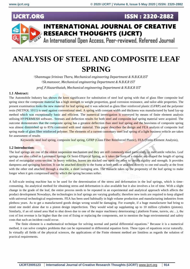
1.4 The U-bolt top plate is important for two reasons:
It manages the U-bolts directly in the line of pull and proper arrangement with each other. When this top plate is eliminated, the long U-
bolts may be pulled up at a slight angle and tight. But when the vehicle flexes the spring, the U-bolts will continuously slide over to
their location and may loosen enough to cause middle spring damage. Because the top plates are molded to fit the profile of the U-bolts,
the U-bolts may be carried up more solidly and more securely.
The top plate shape must mate with the shape of the U-bolt do not use inadequate shaped U-bolts or U-bolts produced on worn dies
which may modify the intended top shape of the U-bolt. On square bend U-bolts, the corner radius must be at least 1/2 the diameter of
the rod i.e. 1" U-bolt legs will have a 1/2" radius at the curve.
Fig: 1.2 Typical center clamping of overslung spring
1.5 Center Bolt and Cupped Centers: The centre bolt assists in collection, shipping and handling of the spring before the spring is placed on the vehicle. After the
spring is put in, the middle bolt assists in preventing:
A. the length-wise shifting of the leaves
B. the width-wise shifting of the leaves
C. acts as an indicator to show the spring is' correctly placed on axle
In all of those functions, it's only an assistant and, once a middle bolt is bent or broken, the U-bolts ought
to be suspected of getting unsuccessful in their full duty of clamp spring in the direction of the axle. Springs that are subjected to
severe loads in the lengthwise motion are cupped to prevent this movement.
Spring Eyes:
Spring eyes should have a free turning, but not a loose fit on the spring pins or shackle bolts. Except once rubber bushings area
unit employed in the spring eyes, as in some applications, the spring pin or shackle bolts should be regularly lubricated wit h
chassis lubricant, to Prevent cooling or binding of the spring eyes on the bolt. Improper lubrication would possibly cause gap of
the attention, or "straight across" breakage of the most leaf close to the attention
1.5.1 Typical Eyes of springs:
Fig 1.3 types of eyes in leaf spring
The military or full loose wrappers overall clearance permits relative lengthwise freedom of the first and second leaves. But if the
attention of the most leaf ought to break, the spring is preserved in situ by the wrapper eye of the second leaf, and also the vehicle will
still be safely transported to the nearest repair facility.
www.ijcrt.org © 2020 IJCRT | Volume 8, Issue 5 May 2020 | ISSN: 2320-2882
IJCRT2005123 International Journal of Creative Research Thoughts (IJCRT) www.ijcrt.org 916
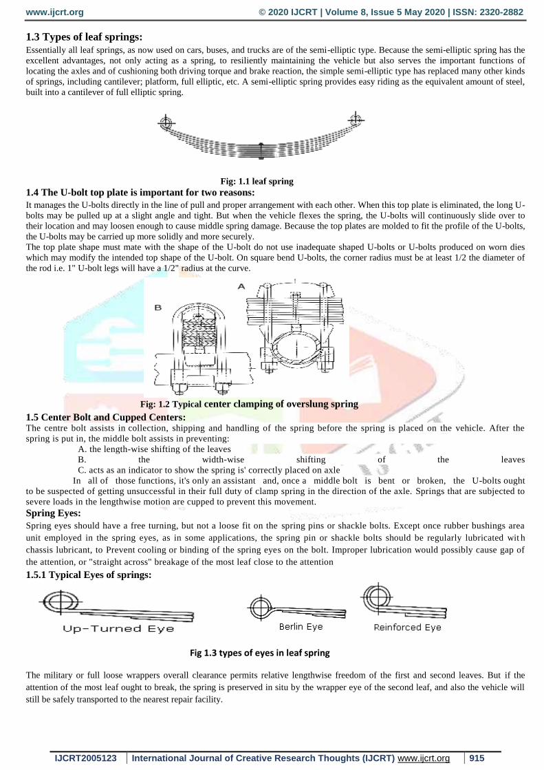
Heavy-Duty Spring Eyes:
Fig 1.4 heavy duty spring eyes
1.6 Adding a leaf:
Adding a leaf, to increase the load carrying capacity of a spring seems so easy... we should think twice before doing so?
Suspension systems unit designed to hold such loads; so its entire part elements designed to hold such elements of this load. In times
of stringent economy, the truck and trailer manufacturer should endeavor to take care or cut back the value of vehicles. So the
suspension elements are unit designed with the minimum acceptable ratio. Adding leaves to a spring might severely overload the
suspension elements or vehicle itself.
A properly designed spring could be a balanced spring, with leaves thus hierarchal or "stepped" long,
with relevancy the opposite leaves, that every leaf carries its fair proportion of the load. The lengths of the leaves of a spring, along
with the thickness and individual leaf radii, verify the distribution of stresses on every leaf
1.7 Adding leaves without this in mind will upset the uniform stress distribution: Any alteration or modification to the original style of a spring might seriously damage the encompassing components of
the suspension system, so putting the vehicle operator in peril of damage or demise by the suspension framework failure.
A - Second Plate Too Short
B - All Backing Plates Too Long correct stepping equalizes
Stress between all plates
Fig: 1.5 uniform stress distributions in leaf spring
1.7.1 Spring Clips:
When a truck wheel hits a bump, the main leaf of the spring is strongly assisted by all the shorter leaves of the spring in resisting the
shock. But, after the bump has been passed, the main leaf would ordinarily have to absorb most of the rebound-all by itself-if the main
leaf was not assisted in absorbing the rebound by the other leaves are connected to the main leaf by means of rebound clips.
Spring clips prevent breakage due to fanning:
The secondary capacity of the rebound back clips is to counteract spreading or "fanning out" of the leaves, which may bring about
possible breakage.. For these two reasons, it is clearly significant that wrecked rebound clips be supplanted by "properly adjusted"
rebound back clips
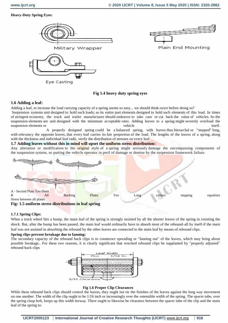
Fig 1.6 Proper Clip Clearances
While these rebound back clips should control the leaves, they ought not tie the finishes of the leaves against the long way movement
on one another. The width of the clip ought to be 1/16 inch or increasingly over the ostensible width of the spring. The spacer tube, over
the spring clasp bolt, keeps up this width leeway. There ought to likewise be clearance between the spacer tube of the clip and the main
leaf of the spring to:
www.ijcrt.org © 2020 IJCRT | Volume 8, Issue 5 May 2020 | ISSN: 2320-2882
IJCRT2005123 International Journal of Creative Research Thoughts (IJCRT) www.ijcrt.org 917
A. Allow the "twist" to be circulated over a more prominent length of the main leaf when one wheel goes over a knock or drops
rut, thus placing the axle at a point of angle. Clips close to the finishes of the spring ought to have more clearance.
B. Clearance counteracts scouring of spacer tube on and ensuing wear and debilitating of the principle leaf.
Clip fasteners ought to be gathered with the head of the screw away from the tire, so that if a nut ought to relax and the clasp screw
comes somewhat out, it won't cut the tire, and the nut end of the fastener ought to be penned over to keep the nut from support off.
1.8 Inspection
Because leaf spring suspensions usually give such trouble free performance, they are apt to be entirely neglected until trouble
actually occurs. However, since springs and chassis elements area unit each operating elements and structural elements, they
will well repay the small amount of inspection and preventive maintenance service necessary to keep them in safest operating
condition.
Such spring suspension examination could also be divided into:
A. Checking the performance of the springs, as shown by vehicle.
B. Checking the springs themselves by actual inspection.
C. Checking all chassis parts for wear.
Visual inspection
Before a vehicle starts out, practiced mechanics will usually spot a sagged spring by the low look of the front fenders. But a a
lot of reliable methodology is to examine the clearance between the chassis frame and therefore the work. Of course the tire
inflation should be thought of, for greater accuracy. The space between floor and wheel rim are often checked. Any tilting or
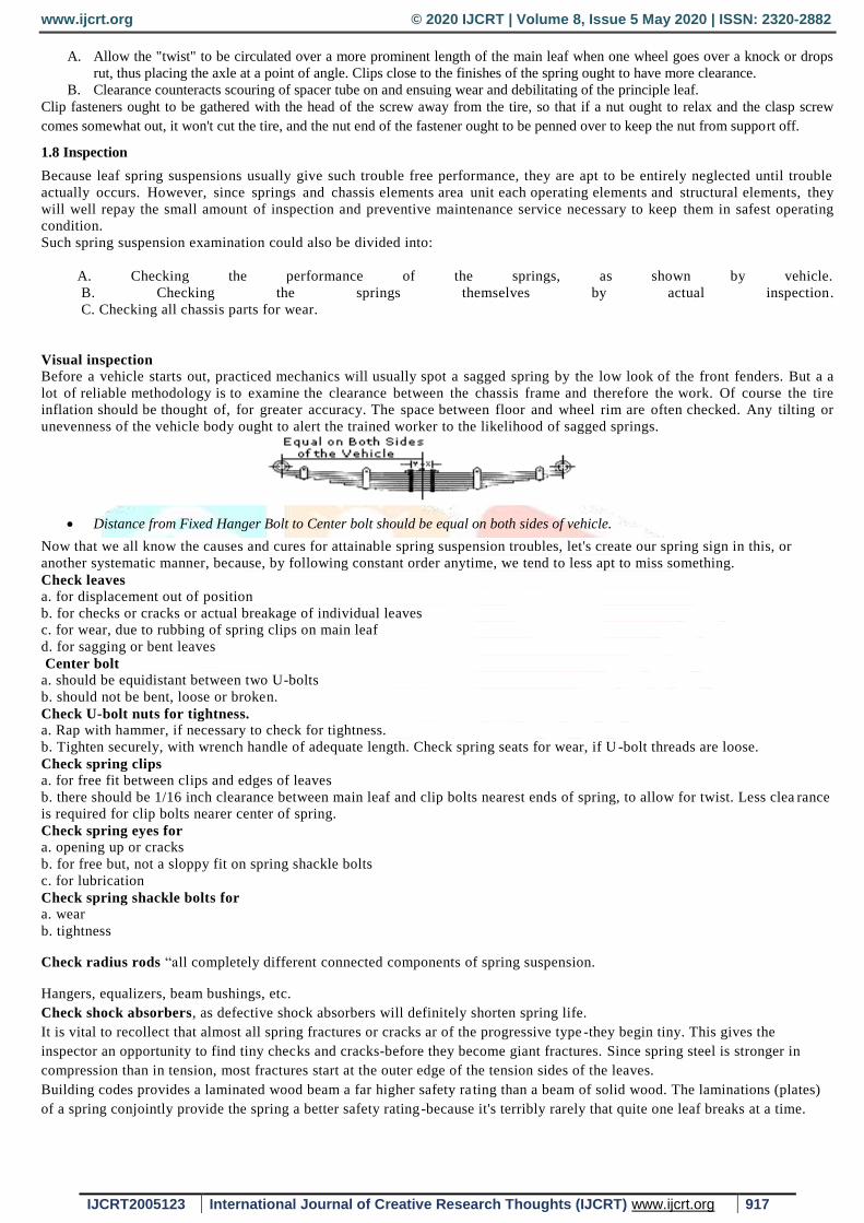
unevenness of the vehicle body ought to alert the trained worker to the likelihood of sagged springs.
Distance from Fixed Hanger Bolt to Center bolt should be equal on both sides of vehicle.
Now that we all know the causes and cures for attainable spring suspension troubles, let's create our spring sign in this, or
another systematic manner, because, by following constant order anytime, we tend to less apt to miss something.
Check leaves a. for displacement out of position
b. for checks or cracks or actual breakage of individual leaves
c. for wear, due to rubbing of spring clips on main leaf
d. for sagging or bent leaves
Center bolt a. should be equidistant between two U-bolts
b. should not be bent, loose or broken.
Check U-bolt nuts for tightness.
a. Rap with hammer, if necessary to check for tightness.
b. Tighten securely, with wrench handle of adequate length. Check spring seats for wear, if U -bolt threads are loose.
Check spring clips a. for free fit between clips and edges of leaves
b. there should be 1/16 inch clearance between main leaf and clip bolts nearest ends of spring, to allow for twist. Less clea rance
is required for clip bolts nearer center of spring.
Check spring eyes for a. opening up or cracks
b. for free but, not a sloppy fit on spring shackle bolts
c. for lubrication
Check spring shackle bolts for a. wear
b. tightness
Check radius rods “all completely different connected components of spring suspension.
Hangers, equalizers, beam bushings, etc.
Check shock absorbers, as defective shock absorbers will definitely shorten spring life.
It is vital to recollect that almost all spring fractures or cracks ar of the progressive type -they begin tiny. This gives the
inspector an opportunity to find tiny checks and cracks-before they become giant fractures. Since spring steel is stronger in
compression than in tension, most fractures start at the outer edge of the tension sides of the leaves.
Building codes provides a laminated wood beam a far higher safety ra ting than a beam of solid wood. The laminations (plates)
of a spring conjointly provide the spring a better safety rating-because it's terribly rarely that quite one leaf breaks at a time.
www.ijcrt.org © 2020 IJCRT | Volume 8, Issue 5 May 2020 | ISSN: 2320-2882
IJCRT2005123 International Journal of Creative Research Thoughts (IJCRT) www.ijcrt.org 918
The breakage of one leaf typically offers "warning" by
1. By the feel of the ride.
2. By the position of the vehicle body.
This gives ample time to exchange it, before other leaves are damaged by the overload. However, let's not overwork this factor
of safety, but use reasonably careful driving to finish the day's run and then replace the broken leaf-before any other leaves are
damaged by the "concentration" of stress over the sting of the broken leaf.
However, if the foremost leaf is broken (unless the second leaf is of the wrapper" kind, or there's a mil itary wrap of the spring
eye) it should be preferable to tow the vehicle to the spring station. With either the military wrap of the second leaf round the
eye of the most leaf, or the wrapper variety of second leaf, the vehicle might typically proceed unde rneath its own power to the
closest repair facility, however this is often not suggested.
Moving a vehicle with a broken main leaf is very unsafe not solely to the operator however to the elements of the suspension
because of abnormal movement of the axle. On the road, A tendency to "strike bottom" or hit the rubber bumpers might result
from:
1.excessive overload.
2.sagged springs.
Springs of recent style are typically nearly flat-under traditional full load conditions. When springs are nearly flat, they are in a
better position to endure constant flexing, and they also tend to act as straight radius rods and so maintain axle positions and
steering alignments more accurately.
Consequently, when such modern springs have "reverse camber," the vehicle may be suspected of:
1. being overloaded
2. Sagged springs
springs of earlier styles typically had additional "arch" or camber and then might not have reverse camber, even when
overloaded or sagged. Position and condition of shackles ought to be noted, to see if the angles of these shackles on the two
sides of the vehicle are the same. The design of spring shackles is such to allow the spring free movement throughout its entire
cycle from unloaded to "striking bottom." Proper design will also slow down the oscillation rate, or rate of bounce, and so gives
a more comfortable ride. The shackle angle, for that individual vehicle, ought to be used as a guide. Wrong shackle angle might
indicate a spring that's too long or too short for that vehicle. Also some gift styles are in reverse camber underneath full load
and don't seem to be overstressed during this position.
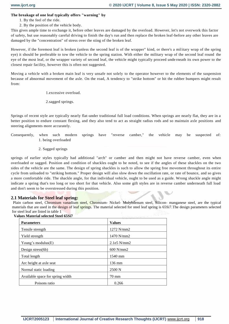
2.1 Materials for Steel leaf spring: Plain carbon steel, Chromium vanadium steel, Chromium- Nickel- Molybdenum steel, Silicon- manganese steel, are the typical
materials that are used in the design of leaf springs. The material selected for steel leaf spring is 65Si7.The design parameters selected
for steel leaf are listed in table 1 Values Material selected Steel 65Si7
Parameters Values
Tensile strength 1272 N/mm2
Yield strength 1470 N/mm2
Young’s modulus(E) 2.1e5 N/mm2
Design stress(6b) 600 N/mm2
Total length 1540 mm
Arc height at axle seat 136 mm
Normal static loading 2500 N
Available space for spring width 70 mm
Poisons ratio 0.266
www.ijcrt.org © 2020 IJCRT | Volume 8, Issue 5 May 2020 | ISSN: 2320-2882
IJCRT2005123 International Journal of Creative Research Thoughts (IJCRT) www.ijcrt.org 919
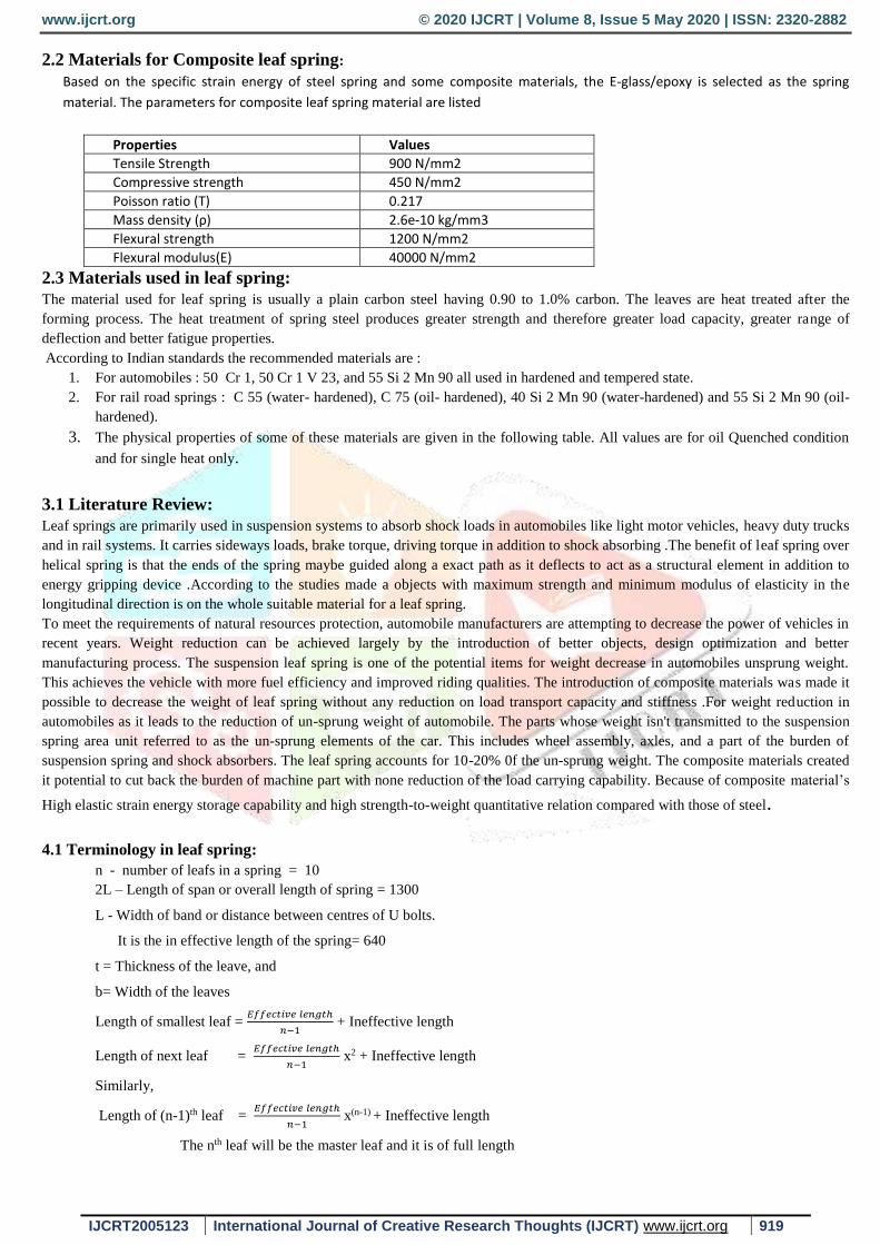
2.2 Materials for Composite leaf spring:
Based on the specific strain energy of steel spring and some composite materials, the E-glass/epoxy is selected as the spring
material. The parameters for composite leaf spring material are listed
Properties Values
Tensile Strength 900 N/mm2
Compressive strength 450 N/mm2
Poisson ratio (T) 0.217
Mass density (ρ) 2.6e-10 kg/mm3
Flexural strength 1200 N/mm2
Flexural modulus(E) 40000 N/mm2
2.3 Materials used in leaf spring:
The material used for leaf spring is usually a plain carbon steel having 0.90 to 1.0% carbon. The leaves are heat treated after the
forming process. The heat treatment of spring steel produces greater strength and therefore greater load capacity, greater range of
deflection and better fatigue properties.
According to Indian standards the recommended materials are :
1. For automobiles : 50 Cr 1, 50 Cr 1 V 23, and 55 Si 2 Mn 90 all used in hardened and tempered state.
2. For rail road springs : C 55 (water- hardened), C 75 (oil- hardened), 40 Si 2 Mn 90 (water-hardened) and 55 Si 2 Mn 90 (oil-
hardened).
3. The physical properties of some of these materials are given in the following table. All values are for oil Quenched condition
and for single heat only.
3.1 Literature Review:
Leaf springs are primarily used in suspension systems to absorb shock loads in automobiles like light motor vehicles, heavy duty trucks
and in rail systems. It carries sideways loads, brake torque, driving torque in addition to shock absorbing .The benefit of leaf spring over
helical spring is that the ends of the spring maybe guided along a exact path as it deflects to act as a structural element in addition to
energy gripping device .According to the studies made a objects with maximum strength and minimum modulus of elasticity in the
longitudinal direction is on the whole suitable material for a leaf spring.
To meet the requirements of natural resources protection, automobile manufacturers are attempting to decrease the power of vehicles in
recent years. Weight reduction can be achieved largely by the introduction of better objects, design optimization and better
manufacturing process. The suspension leaf spring is one of the potential items for weight decrease in automobiles unsprung weight.
This achieves the vehicle with more fuel efficiency and improved riding qualities. The introduction of composite materials was made it
possible to decrease the weight of leaf spring without any reduction on load transport capacity and stiffness .For weight reduction in
automobiles as it leads to the reduction of un-sprung weight of automobile. The parts whose weight isn't transmitted to the suspension
spring area unit referred to as the un-sprung elements of the car. This includes wheel assembly, axles, and a part of the burden of
suspension spring and shock absorbers. The leaf spring accounts for 10-20% 0f the un-sprung weight. The composite materials created
it potential to cut back the burden of machine part with none reduction of the load carrying capability. Because of composite material’s
High elastic strain energy storage capability and high strength-to-weight quantitative relation compared with those of steel.
4.1 Terminology in leaf spring:
n - number of leafs in a spring = 10
2L – Length of span or overall length of spring = 1300
L - Width of band or distance between centres of U bolts.
It is the in effective length of the spring= 640
t = Thickness of the leave, and
b= Width of the leaves
Length of smallest leaf = 𝐸𝑓𝑓𝑒𝑐𝑡𝑖𝑣𝑒 𝑙𝑒𝑛𝑔𝑡ℎ
𝑛−1 + Ineffective length
Length of next leaf = 𝐸𝑓𝑓𝑒𝑐𝑡𝑖𝑣𝑒 𝑙𝑒𝑛𝑔𝑡ℎ
𝑛−1 x2 + Ineffective length
Similarly,
Length of (n-1)th leaf = 𝐸𝑓𝑓𝑒𝑐𝑡𝑖𝑣𝑒 𝑙𝑒𝑛𝑔𝑡ℎ
𝑛−1 x(n-1) + Ineffective length
The nth leaf will be the master leaf and it is of full length
www.ijcrt.org © 2020 IJCRT | Volume 8, Issue 5 May 2020 | ISSN: 2320-2882
IJCRT2005123 International Journal of Creative Research Thoughts (IJCRT) www.ijcrt.org 920
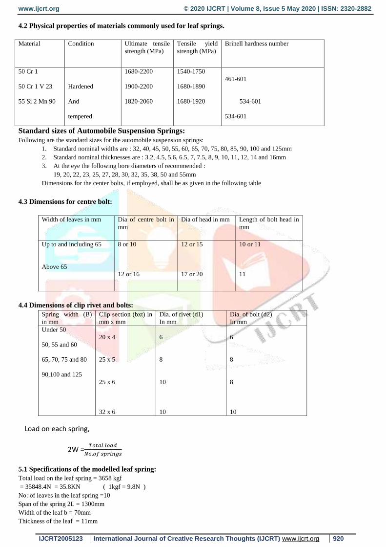
4.2 Physical properties of materials commonly used for leaf springs.
Material Condition Ultimate tensile
strength (MPa)
Tensile yield
strength (MPa)
Brinell hardness number
50 Cr 1
50 Cr 1 V 23
55 Si 2 Mn 90
Hardened
And
tempered
1680-2200
1900-2200
1820-2060
1540-1750
1680-1890
1680-1920
461-601
534-601
534-601
Standard sizes of Automobile Suspension Springs:
Following are the standard sizes for the automobile suspension springs:
1. Standard nominal widths are : 32, 40, 45, 50, 55, 60, 65, 70, 75, 80, 85, 90, 100 and 125mm
2. Standard nominal thicknesses are : 3.2, 4.5, 5.6, 6.5, 7, 7.5, 8, 9, 10, 11, 12, 14 and 16mm
3. At the eye the following bore diameters of recommended :
19, 20, 22, 23, 25, 27, 28, 30, 32, 35, 38, 50 and 55mm
Dimensions for the center bolts, if employed, shall be as given in the following table
4.3 Dimensions for centre bolt:
Width of leaves in mm Dia of centre bolt in
mm
Dia of head in mm Length of bolt head in
mm
Up to and including 65
Above 65
8 or 10
12 or 16
12 or 15
17 or 20
10 or 11
11
4.4 Dimensions of clip rivet and bolts:
Spring width (B)
in mm
Clip section (bxt) in
mm x mm
Dia. of rivet (d1)
In mm
Dia. of bolt (d2)
In mm
Under 50
50, 55 and 60
65, 70, 75 and 80
90,100 and 125
20 x 4
25 x 5
25 x 6
32 x 6
6
8
10
10
6
8
8
10
Load on each spring,
2W =𝑇𝑜𝑡𝑎𝑙 𝑙𝑜𝑎𝑑
𝑁𝑜.𝑜𝑓 𝑠𝑝𝑟𝑖𝑛𝑔𝑠
5.1 Specifications of the modelled leaf spring:
Total load on the leaf spring = 3658 kgf
= 35848.4N = 35.8KN ( 1kgf = 9.8N )
No: of leaves in the leaf spring =10
Span of the spring 2L = 1300mm
Width of the leaf b = 70mm
Thickness of the leaf = 11mm
www.ijcrt.org © 2020 IJCRT | Volume 8, Issue 5 May 2020 | ISSN: 2320-2882
IJCRT2005123 International Journal of Creative Research Thoughts (IJCRT) www.ijcrt.org 921
Bending stress = 6 𝑊 𝐿
𝑛.𝑏.𝑡2 = 1650.63 N/𝑚𝑚2
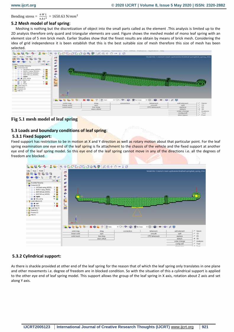
5.2 Mesh model of leaf spring: Meshing is nothing but the discretization of object into the small parts called as the element .This analysis is limited up to the 2D analysis therefore only quard and triangular elements are used. Figure shows the meshed model of mono leaf spring with an element size of 5 mm brick mesh. Earlier Studies show that the finest results are obtain by means of brick mesh. Considering the idea of grid independence it is been establish that this is the best suitable size of mesh therefore this size of mesh has been selected.
Fig 5.1 mesh model of leaf spring
5.3 Loads and boundary conditions of leaf spring: 5.3.1 Fixed Support: Fixed support has restriction to be in motion at X and Y direction as well as rotary motion about that particular point. For the leaf spring examination one eye end of the leaf spring is fix attachment to the chassis of the vehicle and the fixed support at another eye end of the leaf spring model. So this eye end of the leaf spring cannot move in any of the directions i.e. all the degrees of freedom are blocked.
5.3.2 Cylindrical support: As there is shackle provided at other end of the leaf spring for the reason that of which the leaf spring only translates in one plane and other movements i.e. degree of freedom are in blocked condition. So with the situation of this a cylindrical support is applied to the other eye end of leaf spring model. This support allows the group of the leaf spring in X axis, rotation about Z axis and set along Y axis.
www.ijcrt.org © 2020 IJCRT | Volume 8, Issue 5 May 2020 | ISSN: 2320-2882
IJCRT2005123 International Journal of Creative Research Thoughts (IJCRT) www.ijcrt.org 922
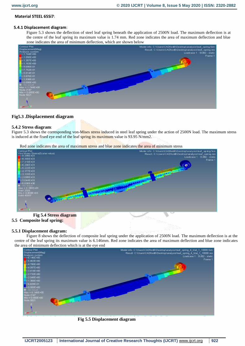
Material STEEL 65Si7: 5.4.1 Displacement diagram:
Figure 5.3 shows the deflection of steel leaf spring beneath the application of 2500N load. The maximum deflection is at
the centre of the leaf spring its maximum value is 1.74 mm. Red zone indicates the area of maximum deflection and blue
zone indicates the area of minimum deflection, which are shown below
Fig5.3 .Displacement diagram
5.4.2 Stress diagram:
Figure 5.3 shows the corresponding von-Mises stress induced in steel leaf spring under the action of 2500N load. The maximum stress
is induced at the fixed eye end of the leaf spring its maximum value is 93.95 N/mm2.
Red zone indicates the area of maximum stress and blue zone indicates the area of minimum stress
Fig 5.4 Stress diagram
5.5 Composite leaf spring:
5.5.1 Displacement diagram:
Figure 8 shows the deflection of composite leaf spring under the application of 2500N load. The maximum deflection is at the
centre of the leaf spring its maximum value is 6.146mm. Red zone indicates the area of maximum deflection and blue zone indicates
the area of minimum deflection which is at the eye end
Fig 5.5 Displacement diagram
www.ijcrt.org © 2020 IJCRT | Volume 8, Issue 5 May 2020 | ISSN: 2320-2882
IJCRT2005123 International Journal of Creative Research Thoughts (IJCRT) www.ijcrt.org 923
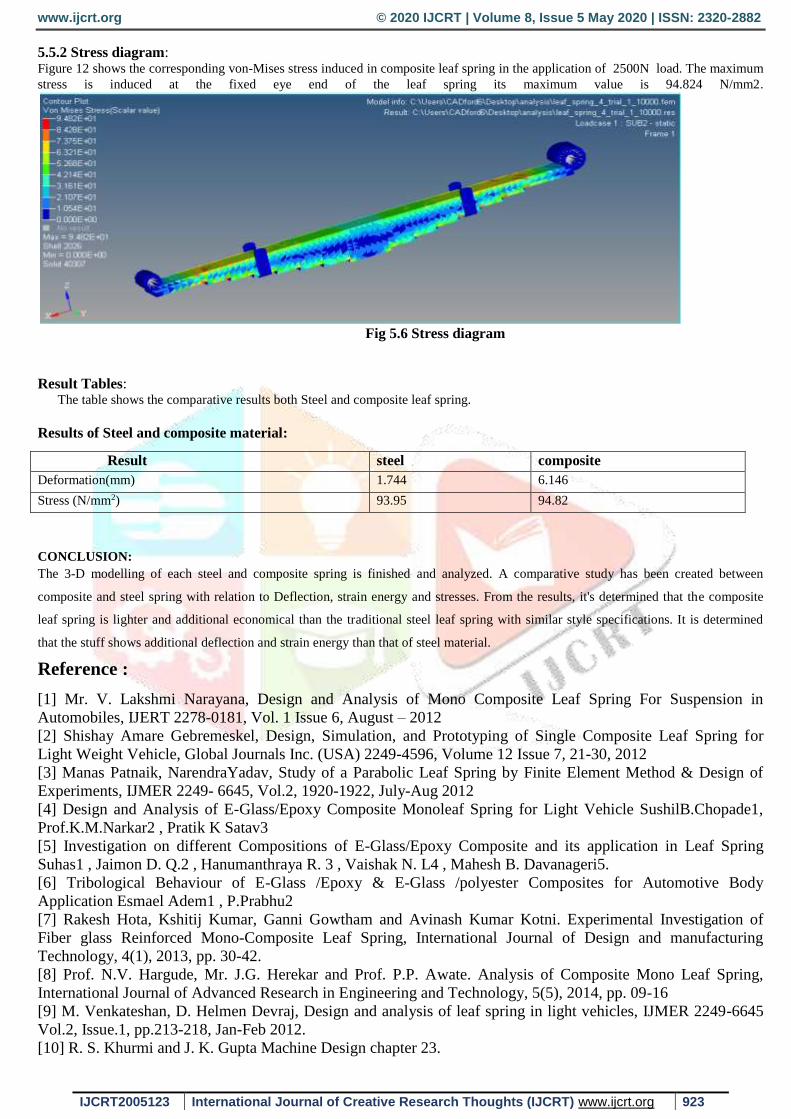
5.5.2 Stress diagram: Figure 12 shows the corresponding von-Mises stress induced in composite leaf spring in the application of 2500N load. The maximum
stress is induced at the fixed eye end of the leaf spring its maximum value is 94.824 N/mm2.
Fig 5.6 Stress diagram
Result Tables: The table shows the comparative results both Steel and composite leaf spring.
Results of Steel and composite material:
CONCLUSION:
The 3-D modelling of each steel and composite spring is finished and analyzed. A comparative study has been created between
composite and steel spring with relation to Deflection, strain energy and stresses. From the results, it's determined that the composite
leaf spring is lighter and additional economical than the traditional steel leaf spring with similar style specifications. It is determined
that the stuff shows additional deflection and strain energy than that of steel material.
Reference :
[1] Mr. V. Lakshmi Narayana, Design and Analysis of Mono Composite Leaf Spring For Suspension in
Automobiles, IJERT 2278-0181, Vol. 1 Issue 6, August – 2012
[2] Shishay Amare Gebremeskel, Design, Simulation, and Prototyping of Single Composite Leaf Spring for
Light Weight Vehicle, Global Journals Inc. (USA) 2249-4596, Volume 12 Issue 7, 21-30, 2012
[3] Manas Patnaik, NarendraYadav, Study of a Parabolic Leaf Spring by Finite Element Method & Design of
Experiments, IJMER 2249- 6645, Vol.2, 1920-1922, July-Aug 2012
[4] Design and Analysis of E-Glass/Epoxy Composite Monoleaf Spring for Light Vehicle SushilB.Chopade1,
Prof.K.M.Narkar2 , Pratik K Satav3
[5] Investigation on different Compositions of E-Glass/Epoxy Composite and its application in Leaf Spring
Suhas1 , Jaimon D. Q.2 , Hanumanthraya R. 3 , Vaishak N. L4 , Mahesh B. Davanageri5.
[6] Tribological Behaviour of E-Glass /Epoxy & E-Glass /polyester Composites for Automotive Body
Application Esmael Adem1 , P.Prabhu2
[7] Rakesh Hota, Kshitij Kumar, Ganni Gowtham and Avinash Kumar Kotni. Experimental Investigation of
Fiber glass Reinforced Mono-Composite Leaf Spring, International Journal of Design and manufacturing
Technology, 4(1), 2013, pp. 30-42.
[8] Prof. N.V. Hargude, Mr. J.G. Herekar and Prof. P.P. Awate. Analysis of Composite Mono Leaf Spring,
International Journal of Advanced Research in Engineering and Technology, 5(5), 2014, pp. 09-16
[9] M. Venkateshan, D. Helmen Devraj, Design and analysis of leaf spring in light vehicles, IJMER 2249-6645
Vol.2, Issue.1, pp.213-218, Jan-Feb 2012.
[10] R. S. Khurmi and J. K. Gupta Machine Design chapter 23.
Result steel composite
Deformation(mm) 1.744 6.146
Stress (N/mm2) 93.95 94.82

www.ijcrt.org © 2020 IJCRT | Volume 8, Issue 5 May 2020 | ISSN: 2320-2882
IJCRT2005123 International Journal of Creative Research Thoughts (IJCRT) www.ijcrt.org 924
[11] U. S. Ramakant & K. Sowjanya, Design and analysis of automotive multi leaf springs using composite
material, IJMPERD 2249-6890 Vol. 3, Issue 1,pp.155-162, March 2013,
[12] Rajendran I, Vijayarangan S, Design and Analysis of a Composite Leaf Spring, Journal of Institute of
Engineers, India ,vol.-8,2-2002
[13] Dakshraj Kothari,Rajendra Prasad Sahu and Rajesh Satankar Comparison ofPerformance of Two Leaf
Spring Steels Used For Light Passenger Vehicle, VSRD-MAP 2249-8303 Volume2 (1), 9-16, 2012
Related Documents