METALS AND MATERIALS, Vol. 5, No. 4 (1999), pp. 369-375 Analysis of Heat Transfer in Hot Rolled Coils for Optimum Condition of Forced Cooling Seung Chul Baik, Ohjoon Kwon, Seong-Jun Park*, Byung-Hee Hong* and Kyu Hwan Oh* Technical Research Lab., Pohang Iron & Steel Co. Ltd. 1 Goedong-dong, Nam-ku, Pohang 790-785, Korea *Research Institute of Advanced Materials Division of Materials Science and Engineering, Seoul National University San 56-1 Shinrim-dong, Kwanak-ku, Seoul 151-742, Korea A new equation was proposed to investigate the heat transfer in the hot rolled coils by taking account of the variation of contact between coiled layers. The proposed equation was represented by the equivalent radial thermal conductivity as a function of radial normal pressure. It was found that the analytical results were in good agreement with the experimental data. The cooling times of the hot rolled coils of various dimensions cooled by air or water have been calculated by using the proposed equation. It was shown by finite element analyses that the cooling time was decreased from 32-53 hours to 6-13 hours for spray water cooling. Key words:hot rolled steel sheet, heat transfer, coiling 1. INTRODUCTION Hot rolled strips are coiled at 540-720~ and cooled to room temperature for the subsequent pickling process. Depending on the coil size and the air temperature, the nat- ural cooling of hot coils takes 3-5 days. The forced cool- ing of coils decreases the cooling time, enabling short delivery times and reductions in the size of coil yard. Hot coils can be rapidly cooled by sprayed water. It is nec- essary to analyse the cooling rate of hot coils to optimize the cooling condition which is dependent on the coil size, the steel type and the temperature of coolants. The procedure for analysing the heat transfer in hot rolled coils is generally based on treating the hot rolled coil as an equivalent solid material. The equivalent radial thermal conductivity is different from the equivalent axial thermal conductivity in the equivalent solid material because the hot coil is made by the lapping of a hot rolled strip in a hollow cylindrical shape. The equivalent axial thermal conductivity can be obtained by averaging the thermal conductivities of the steel, oxide and air layers. The air and oxide layers can be neglected in the cal- culation of the equivalent axial thermal conductivity because the thickness and thermal conductivities of oxide and air layers are much smaller than that of the steel layer. On the contrary, the equivalent radial thermal conduc- tivity depends on the thickness of the air layers because of the heat transfer through the steel, oxide and air layers sequentially in the radial direction of the hot roiled coil. Also, the thickness of the air layer changes during cooling due to the thermal contradiction. Several attempts [1-3] have been made to derive the equivalent radial thermal conductivity and to analyse the heat transfer in the coil. However, the change in the thickness of air layers during cooling by thermal contradiction has not been taken into account in the previous investigations. The purpose of this paper was to analyse the heat trans- fer phenomena in hot coils by using the concept of the equivalent radial thermal conductivity, which took into account the variation of contact between coiled steel layers by the thermal effect. 2. MODELING OF EQUIVALENT RADIAL THERMAL CONDUCTIVITY Fig. 1 shows the schematic diagram of steel, oxide and air layers overlapped sequentially in hot rolled coil. Because heat transfers through steel, oxide and air layers, the thermal resistance in the radial direction, R, becomes Rr = t._;= Rs+2Ro+R a (1) kr where k~ is the equivalent radial thermal conductivity, t is the thickness of one unit layer containing a steel layer, an air layer and two oxide layers, and R,, Ro and R,, are the thermal- resistances of steel, air and oxide layers, respectively.

Welcome message from author
This document is posted to help you gain knowledge. Please leave a comment to let me know what you think about it! Share it to your friends and learn new things together.
Transcript
METALS AND MATERIALS, Vol. 5, No. 4 (1999), pp. 369-375
Analysis of Heat Transfer in Hot Rolled Coils for Optimum Condition of Forced Cooling
Seung Chul Baik, Ohjoon Kwon, Seong-Jun Park*, Byung-Hee Hong* and Kyu Hwan Oh*
Technical Research Lab., Pohang Iron & Steel Co. Ltd. 1 Goedong-dong, Nam-ku, Pohang 790-785, Korea
*Research Institute of Advanced Materials Division of Materials Science and Engineering, Seoul National University
San 56-1 Shinrim-dong, Kwanak-ku, Seoul 151-742, Korea
A new equation was proposed to investigate the heat transfer in the hot rolled coils by taking account of the variation of contact between coiled layers. The proposed equation was represented by the equivalent radial thermal conductivity as a function of radial normal pressure. It was found that the analytical results were in good agreement with the experimental data. The cooling times of the hot rolled coils of various dimensions cooled by air or water have been calculated by using the proposed equation. It was shown by finite element analyses that the cooling time was decreased from 32-53 hours to 6-13 hours for spray water cooling.
Key words:hot rolled steel sheet, heat transfer, coiling
1. I N T R O D U C T I O N
Hot rolled strips are coiled at 540-720~ and cooled to room temperature for the subsequent pickling process. Depending on the coil size and the air temperature, the nat- ural cooling of hot coils takes 3-5 days. The forced cool- ing of coils decreases the cooling time, enabling short delivery times and reductions in the size of coil yard. Hot coils can be rapidly cooled by sprayed water. It is nec- essary to analyse the cooling rate of hot coils to optimize the cooling condition which is dependent on the coil size, the steel type and the temperature of coolants.
The procedure for analysing the heat transfer in hot rolled coils is generally based on treating the hot rolled coil as an equivalent solid material. The equivalent radial thermal conductivity is different from the equivalent axial thermal conductivity in the equivalent solid material because the hot coil is made by the lapping of a hot rolled strip in a hollow cylindrical shape. The equivalent axial thermal conductivity can be obtained by averaging the thermal conductivities of the steel, oxide and air layers. The air and oxide layers can be neglected in the cal- culation of the equivalent axial thermal conductivity because the thickness and thermal conductivities of oxide and air layers are much smaller than that of the steel layer. On the contrary, the equivalent radial thermal conduc- tivity depends on the thickness of the air layers because of the heat transfer through the steel, oxide and air layers
sequentially in the radial direction of the hot roiled coil. Also, the thickness of the air layer changes during cooling due to the thermal contradiction. Several attempts [1-3] have been made to derive the equivalent radial thermal conductivity and to analyse the heat transfer in the coil. However, the change in the thickness of air layers during cooling by thermal contradiction has not been taken into account in the previous investigations.
The purpose of this paper was to analyse the heat trans- fer phenomena in hot coils by using the concept of the equivalent radial thermal conductivity, which took into account the variation of contact between coiled steel layers by the thermal effect.
2. MODELING OF E Q U I V A L E N T R A D I A L T H E R M A L C O N D U C T I V I T Y
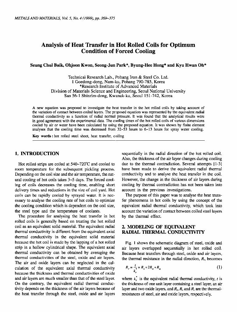
Fig. 1 shows the schematic diagram of steel, oxide and air layers overlapped sequentially in hot rolled coil. Because heat transfers through steel, oxide and air layers, the thermal resistance in the radial direction, R, becomes
Rr = t._; = R s + 2 R o + R a (1) kr
where k~ is the equivalent radial thermal conductivity, t is the thickness of one unit layer containing a steel layer, an air layer and two oxide layers, and R,, Ro and R,, are the thermal- resistances of steel, air and oxide layers, respectively.
3 7 0 Seung Chul Baik et al.
Fig. 1. Schematic diagram of the overlapped hot rolled sheets and structure of thermal resistances in the radial direction.
The thermal resistances of steel and oxide layers are cal- culated using the following Eq. 2
ts Rs = ~_
t s _ ._eo (2)
R~ k,,
where k~ and k,, are the thermal conductivities of steel and oxide layers, and t, and t,, are the thicknesses of steel and oxide layers, respectively.
All three of the heat transfer modes-conduction, con- vection and radiation-have to be taken into account in the derivation of the equation for the thermal resistance of an air layer. The thermal resistance of an air layer becomes.
1 1 + 1 + 1 / ~ - ~ ~ ~ (3)
where R,.,~, R,,,, and R,r~ are the thermal resistances of con- duction, convection and radiation, respectively.
The heat can be transferred by conduction through air and by the oxide asperities in the air layer because the asperities in the oxide layers may produce a contacted area
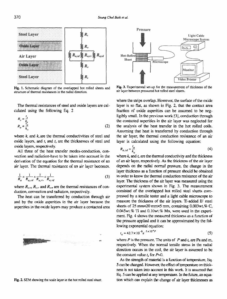
Fig. 2. SEM showing the scale layer in the hot rolled steel sheet.
Fig. 3. Experimental set-up for the measurement of thickness of the air layer between pressured hot rolled steel sheets.
where the strips overlap. However, the surface of the oxide layer is so flat, as shown in Fig. 2, that the contact area fraction of oxide asperities can be assumed to be neg- ligibly small. In the previous work [3], conduction through the contacted asperities in the air layer was neglected for the analysis of the heat transfer in the hot rolled coils. Assuming that heat is transferred by conduction through the air layer, the thermal conduction resistance of an air layer is calculated using the following equation:
t a R~, ca = ~ (4)
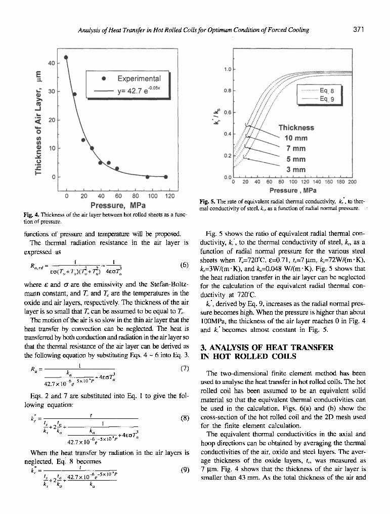
where/~ and t, are the thermal conductivity and the thickness of an air layer, respectively. As the thickness of the air layer depends on the radial normal pressure, the change in the layer thickness as a function of pressure should be obtained in order to know the thermal conduction resistance of the air layer. The thickness of the air layer was measured using the experimental system shown in Fig. 3. The measurement consisted of the overlapped hot rolled steel sheets com- pressed by a tensile tester and a light cable microscope to measure the thickness of the air layers. Ti-added IF steel sheets of 25 mmx20 minx5 ram, containing 0.003wt.% C, 0.045wt.% Ti and 0.10wt.% Mn, were used in the experi- ment. Fig. 4 shows the measured thickness as a function of the pressure applied and it can be approximated by the fol- lowing exponential equation:
t o = 42.7 • 10-6e -5 • 10 ' e (5)
where P is the pressure. The units of P and to are Pa and m, respectively. When the normal tensile stress in the radial direction occurs in the coil, the air layer is assumed to be the constant value t, for P=0.
As the strength of material is a function of temperature, Eq. 5 can be changed. However, the effect of temperature on thick- ness is not taken into account in this work. It is assumed that Eq. 5 can be applied at any temperature. In the future, an equa- tion which can explain the change of air layer thicknesses as
Analysis of Heat Transfer in Hot Rolled Coils for Optimum Condition of Forced Cooling 3 7]
Fig. 4. Thickness of the air layer between hot rolled sheets as a func- tion of pressure.
functions of pressure and temperature will be proposed. The thermal radiation resistance in the air layer is
expressed as
R,,.,.d = l = 1 (6) E o ( T o + T . ) ( d + T]~) 4EO'~]
where e and a are the emissivity and the Stefan-Boltz- mann constant, and T,, and T,, are the temperatures in the
oxide and air layers, respectively. The thickness of the air layer is so small that T,, can be assumed to be equal to To.
The motion of the air is so slow in the thin air layer that the heat transfer by convection can be neglected. The heat is transferred by both conduction and radiation in the air layer so that the thermal resistance of the air layer can be derived as the following equation by substituting Eqs. 4 - 6 into Eq. 3.
1 (7 ) R a = ka
42.7 • 10-6e 5 x 10 "P + 4E~
Eqs. 2 and 7 are substituted into Eq. 1 to give the fol- lowing equation:
= ' ( 8 ) t ~. t o 1 " + 2 - - +
k.~ k o k a
42.7 • 10~6e -5 x l0 ~t" + 4a~
When the heat transfer by radiation in the air layers is neglected, Eql 8 becomes
kr" = t (9) t~ t o 42.7 • 10-6e -5x10 ~P -="+2--+ k s ko ku
Fig. 5. The rate of equivalent radial thermal conductivity, kr, to ther- mal conductivity of steel, k~. as a function of radial normal pressure.
Fig. 5 shows the ratio of equivalent radial thermal con- ductivity, k,', to the thermal conductivity of steel, k, as a function of radial normal pressure for the various steel sheets when T,,=720~ e=0.71, to=7 lam, k,=72W/(m'K), k,,=3W/(m'K), and k,,=0.048 W/(m" K). Fig. 5 shows that the heat radiation transfer in the air layer can be neglected for the calculation of the equivalent radial thermal con-
ductivity at 720"C. k/, derived by Eq. 9, increases as the radial normal pres-
sure becomes high. When the pressure is higher than about 100MPa, the thickness of the air layer reaches 0 in Fig. 4 and k/becomes almost constant in Fig. 5.
3. A N A L Y S I S O F H E A T T R A N S F E R IN H O T R O L L E D C O I L S
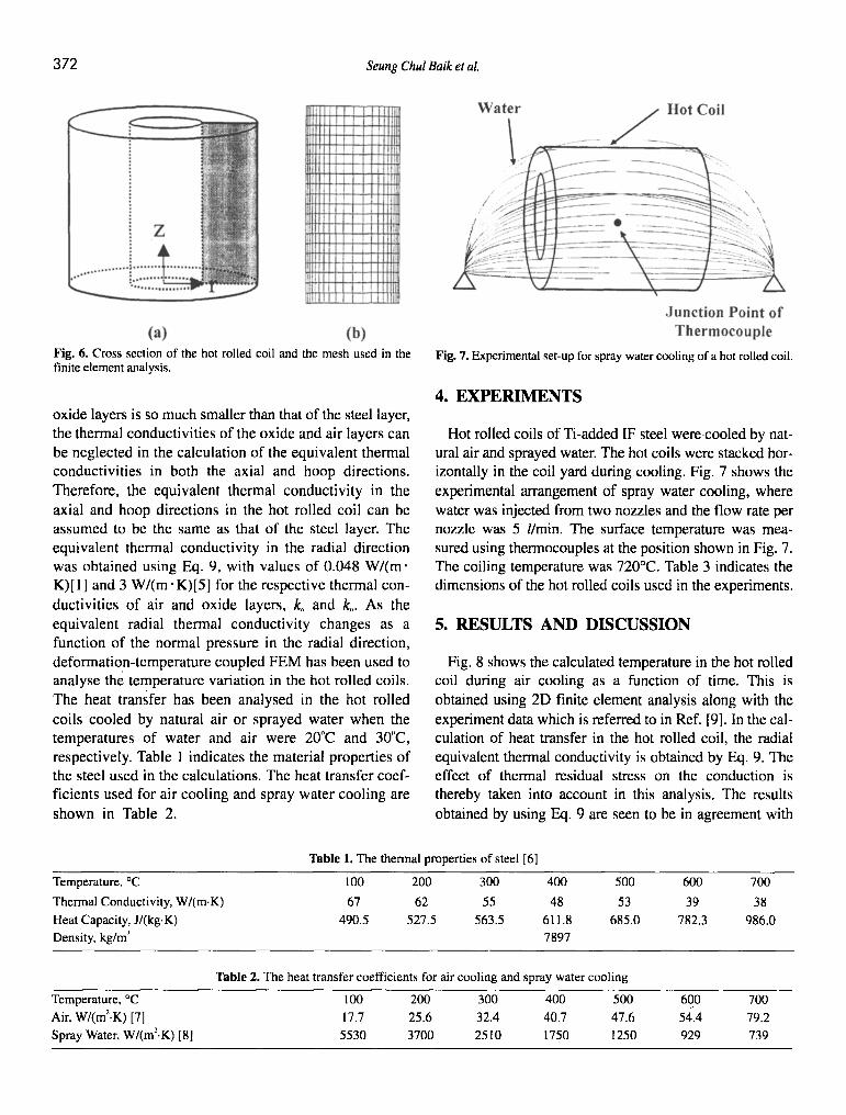
The two-dimensional finite element method has been used to analyse the heat transfer in hot rolled coils. The hot rolled coil has been assumed to be an equivalent solid material so that the equivalent thermal conductivities can be used in the calculation. Figs. 6(a) and (b) show the cross-section of the hot rolled coil and the 2D mesh used for the finite element calculation.
The equivalent thermal conductivities in the axial and hoop directions can be obtained by averaging the thermal conductivities of the air, oxide and steel layers. The aver- age thickness of the oxide layers, t,,, was measured as 7 lam. Fig. 4 shows that the thickness of the air layer is smaller than 43 ram. As the total thickness of the air and
372 Seung Chul Baik et al.
Fig. 6. Cross section of the hot rolled coil and the mesh used in the finite element analysis.
oxide layers is so much smaller than that of the steel layer, the thermal conductivities of the oxide and air layers can be neglected in the calculation of the equivalent thermal conductivities in both the axial and hoop directions. Therefore, the equivalent thermal conductivity in the axial and hoop directions in the hot rolled coil can be assumed to be the same as that of the steel layer. The equivalent thermal conductivity in the radial direction was obtained using Eq. 9, with values of 0.048 W/(m" K)[ 1 ] and 3 W/(m" K)[5] for the respective thermal con- ductivities of air and oxide layers, k, and k,. As the equivalent radial thermal conductivity changes as a function of the normal pressure in the radial direction, deformation-temperature coupled FEM has been used to analyse the temperature variation in the hot rolled coils. The heat transfer has been analysed in the hot rolled coils cooled by natural air or sprayed water when the temperatures of water and air were 20'~C and 30"C, respectively. Table 1 indicates the material properties of the steel used in the calculations. The heat transfer coef- ficients used for air cooling and spray water cooling are shown in Table 2.
Fig. 7. Experimental set-up for spray water cooling of a hot rolled coil.
4. E X P E R I M E N T S
Hot rolled coils of Ti-added IF steel were.cooled by nat- ural air and sprayed water. The hot coils were stacked hor- izontally in the coil yard during cooling. Fig. 7 shows the experimental arrangement of spray water cooling, where water was injected from two nozzles and the flow rate per nozzle was 5 l/rain. The surface temperature was mea- sured using thermocouples at the position shown in Fig. 7. The coiling temperature was 720~ Table 3 indicates the dimensions of the hot rolled coils used in the experiments.
5. R E S U L T S A N D D I S C U S S I O N
Fig. 8 shows the calculated temperature in the hot rolled coil during air cooling as a function of time. This is obtained using 2D finite element analysis along with the experiment data which is referred to in Ref. [9]. In the cal- culation of heat transfer in the hot rolled coil, the radial equivalent thermal conductivity is obtained by Eq. 9. The effect of thermal residual stress on the conduction is thereby taken into account in this analysis. The results obtained by using Eq. 9 are seen to be in agreement with
Table 1. The thermal properties of steel [6]
Temperature, ~ 100 200 300 400 500 600 700
Thermal Conductivity, W/(m.K) 67 62 55 48 53 39 38
Heat Capacity, J/(kg.K) 490.5 527.5 563.5 611.8 685.0 782.3 986.0
Density, kg/m ~ 7897
Table 2. The heat transfer coefficients for air cooling and spray water cooling
Temperature, ~ 100 200 300 400 500 600 700
Air, W/(m2.K) [7] 17.7 25.6 32.4 40.7 47.6 54.4 79.2
Spray Water, W/(m ~'. K) [8] 5530 3700 2510 1750 1250 929 739
Analysis of Heat Transfer in Hot Rolled Coils for Optimum Condition of Forced Cooling 3 73
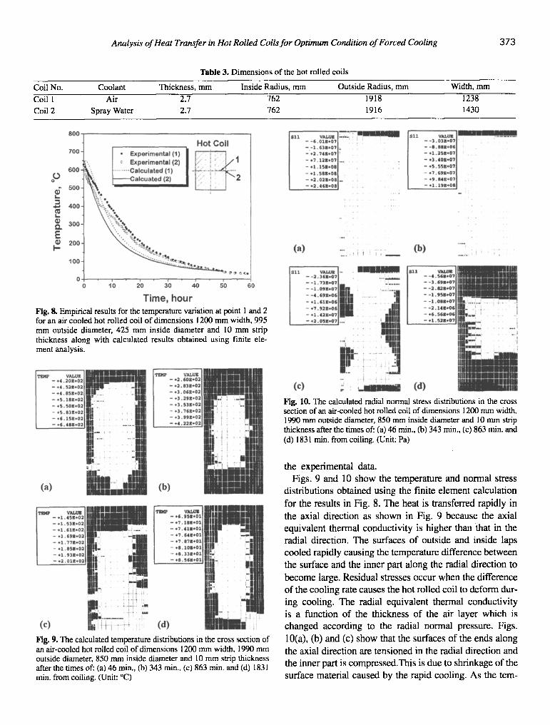
Table 3. Dimensions of the hot rolled coils
Coil No. Coolant Thickness, mm Inside Radius, mm Outside Radius, mm Width, mm
Coil 1 Air 2.7 762 1918 1238 Coil 2 Spray Water 2.7 "?62 1916 1430
Fig. 8. Empirical results for the temperature variation at point 1 and 2 for an air cooled hot rolled coil of dimensions 1200 mm width, 995 mm outside diameter, 425 mm inside diameter and 10 mm strip thickness along with calculated results obtained using finite ele- ment analysis.
Fig. 9. The calculated temperature distributions in the cross section of an air-cooled hot rolled coil of dimensions 1200 mm width, 1990 mm outside diameter, 850 mm inside diameter and 10 mm strip thickness after the times of: (a) 46 rain., (b) 343 min., (c) 863 min. and (d) 1831 min. from coiling. (Unit: ~
Fig. 10. The calculated radial normal stress distributions in the cross section of an air-cooled hot rolled coil of dimensions 1200 mm width, 1990 mm outside diameter, 850 mm inside diameter and 10 mm strip thickness after the times of: (a) 46 rain., (b) 343 rain., (c) 863 rain. and (d) 1831 min. from coiling. (Unit: Pa)
the experimental data.
Figs. 9 and 10 show the temperature and normal stress
distributions obtained using the finite element calculation
for the results in Fig. 8. The heat is transferred rapidly in
the axial direction as shown in Fig. 9 because the axial
equivalent thermal conductivi ty is higher than that in the
radial direction. The surfaces o f outside and inside laps
cooled rapidly causing the temperature difference between
the surface and the inner part along the radial direction to
become large, Residual stresses occur when the difference
o f the cooling rate causes the hot rolled coil to deform dur-
ing cooling. The radial equivalent thermal conductivity
is a function o f the thickness o f the air layer which is
changed according to the radial normal pressure. Figs.
10(a), (b) and (c) show that the surfaces o f the ends along
the axial direction are tensioned in the radial direction and
the inner part is compressed.This is due to shrinkage of the
surface material caused by the rapid cooling. As the tern-
3 74 Seung Chul Baik et al.
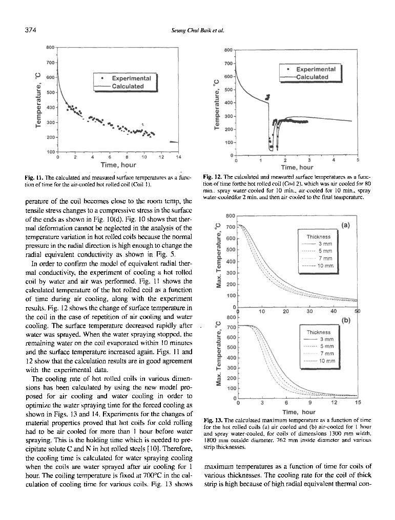
Fig. 11. The calculated and measured surface temperatures as a func- tion of time for the air-cooled hot rolled coil (Coil 1 ).
perature of the coil becomes close to the room temp, the
tensile stress changes to a compressive stress in the surface of the ends as shown in Fig. 10(d). Fig. 10 shows that ther- mal deformation cannot be neglected in the analysis of the temperature variation in hot rolled coils because the normal pressure in the radial direction is high enough to change the
radial equivalent conductivity as shown in Fig. 5.
In order to confirm the model of equivalent radial ther- mal conductivity, the experiment of cooling a hot rolled coil by water and air was performed. Fig. 11 shows the calculated temperature of the hot rolled coil as a function of time during air cooling, along with the experiment
results. Fig. 12 shows the change of surface temperature in the coil in the case of repetition of air cooling and water cooling. The surface temperature decreased rapidly after water was sprayed. When the water spraying stopped, the remaining water on the coil evaporated within 10 minutes
and the surface temperature increased again. Figs. I i and
12 show that the calculation results are in good agreement with the experimental data.
The cooling rate of hot rolled coils in various dimen- sions has been calculated by using the new model pro- posed for air cooling and water cooling in order to
optimize the water spraying time for the forced cooling as shown in Figs. 13 and 14. Experiments for the changes of material properties proved that hot coils for cold rolling had to be air cooled for more than 1 hour before water spraying. This is the holding time which is needed to pre- cipitate solute C and N in hot rolled steels [10]. Therefore,
the cooling time is calculated for water spraying cooling when the coils are water sprayed after air cooling for 1 hour. The coiling temperature is fixed at 700~ in the cal- culation of cooling time for various coils. Fig. 13 shows
Fig. 12. The calculated and measured surface temperatures as a func- tion of time forthe hot rolled coil (Coil 2). which was air-cooled for 80 min., spray water-cooled for 10 rain., air-cooled for 10 min., spray water-cooledtbr 2 rain. and then air-cooled to the final temperature.
Fig. 13. The calculated maximum temperature as a function of time for the hot rolled coils (a) air-cooled and (b) air-cooled for 1 hour and spray water-cooled, for coils of dimensions 1300 mrn width, 1800 mm outside diameter. 762 mm inside diameter and various strip thicknesses.
maximum temperatures as a function of time for coils of various thicknesses. The cooling rate for the coil of thick strip is high because of high radial equivalent thermal con-
Analysis of Heat Transfer in Hot Rolled Coils for Optimum Condition of Forced Cooling 3 75
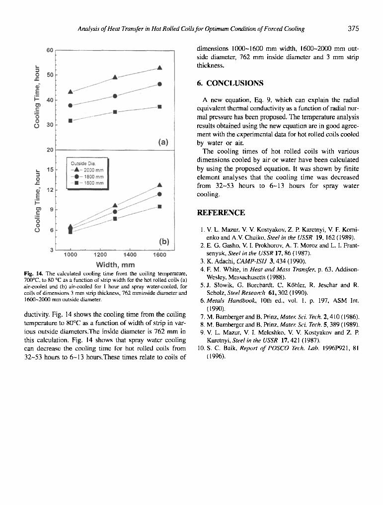
dimensions 1000-1600 mm width, 1600-2000 m m out- side diameter, 762 mm inside diameter and 3 mm strip thickness.
6. CONCLUSIONS
A new equation, Eq. 9, which can explain the radial equivalent thermal conductivity as a function of radial nor-
mal pressure has been proposed. The temperature analysis
results obtained using the new equation are in good agree- ment with the experimental data for hot rolled coils cooled
by water or air. The cooling times of hot rolled coils with various
dimensions cooled by air or water have been calculated
by using the proposed equation. It was shown by finite
element analyses that the cooling time was decreased from 32-53 hours to 6 -13 hours for spray water
cooling.
REFERENCE
Fig. 14. The calculated cooling time from the coiling temperature, 700~ to 80 ~ as a function of strip width for the hot rolled coils (a) air-cooled and (b) air-cooled for 1 hour and spray water-c~x~led, for coils of dimensions 3 mm strip thickness, 762 mminside diameter and 1600-2000 mm outside diameter.
ductivity. Fig. 14 shows the cooling time from the coiling temperature to 80~ as a function of width of strip in var-
ious outside diameters.The inside diameter is 762 mm in this calculation. Fig. 14 shows that spray water cooling can decrease the cooling time for hot rolled coils from
32-53 hours to 6-13 hours.These times relate to coils of
1. V. L. Mazur, V. V. Kostyakov, Z. P. Karetnyi, V. E Komi- enko and A.V. Chuiko, Steel in the USSR 19, 162 (1989).
2. E. G. Gasho, V. I. Prokhorov, A. T. Moroz and L. I. Frant- senyuk, Steel in the USSR 17, 86 (1987).
3. K. Adachi, CAMP-ISIJ 3, 434 (1990). 4. E M. White, in Heat atut Mass Transfer, p. 63, Addison-
Wesley, Messachusetts (1988). 5. J. Slowik, G. Borchardt, C. Krhler, R. Jeschar and R.
Scholz, Steel Research 61,302 (1990). 6. Metals Handbook, 10th ed., vol. 1, p. 197, ASM Int.
(199O). 7. M. Bamberger and B. Prinz, Mater. Sci. Tech. 2, 410 (1986). 8. M. Bamberger and B. Prinz, Mater. Sci. Tech. 5, 389 (1989). 9. V. L. Mazur, V. I. Meleshko, V. V. Kostyakov and Z. E
Karetnyi, Steel in the USSR 17. 421 (1987). I0. S. C. Baik, Report ofPOSCO Tech. Lab. 1996P921, 81
(1996).
Related Documents