Chemistry and Materials Research www.iiste.org ISSN 2224- 3224 (Print) ISSN 2225- 0956 (Online) Vol 2, No.6, 2012 11 ANALYSIS OF GRE PIPES WITH EPOXY RESIN COMPOSITE MATERIAL AND MATERIAL TEST SPECIFICATION Thiyagarajan K 1* , Maria Antoine Pushparaj 2 & Shanmugam 3 1. Department of Mechanical Engineering, Mailam Engineering College, Mailam, India. 2. School of Management, S.R.M. University, Kattangulathur, Chennai, India. 3. School of Mechanical Engineering, S.R.M. University, Kattangulathur, Chennai, India. * E-mail of the corresponding author : [email protected] Abstract At present scenario composite materials has been extensively used in variety of fields right from households to aircrafts for its superior properties like lower specific weight, strength to weight ratio and modulus to weight ratio. In this project effort has been made to extend its application to pipes. Conventional pipes have its own disadvantages such as higher specific weight, low corrosion resistance and low strength which can be replaced by the composite pipes .Design of composite pipe has been done as conventional pipe for its inner diameter and its wall thickness. Structural analysis has been made with ANSYS 12 for its deformation and stress. Comparative study of ANSYS results for M.S.PIPES, and GRE pipes were done to justify the usage of GRE pipes.Filament winding process has been adopted to manufacture GRE pipes in a conventional lathe by implementing a winding setup. Hardness test and compressive test of GRE pipes to be done to assess its strength, leak and corrosion test for its ability to carry liquids. Key words:- {σ} ij -Stress component, [C] ijkl- Stiffness marix, {ε } ij - Strain component , [S] ijkl - Compliance matrix , GRE - Glass reinforced epoxy, PAN - Poly acrylo nitrile. 1. Introduction To Composite Materials 1.1 Polymer matrix composites PMC are the one where matrix materials are made up of various polymers. Numerous amounts of polymer resin combinations are possible. Technically polymers are called as Resin. Typical classification of resins is thermoplastic resin and thermosetting resin. Various fibres such as carbon fibres, Kevlar fibres, SiC fibres and glass fibres can be used as reinforcement materials. 2. Polymer Matrix Composites. 2.1 Thermo sets Thermo set resins which readily Cross-link during curing. Curing involves application of temperature, pressure, and catalyst known as curing agent. Polyester, phenolics, polyimide and Epoxy are the typical thermosetting resin. 2. 2 Thermoplastics Thermoplastics readily flow under stress at elevated temperatures, so allowing them to be fabricated into the required component, and become solid and retain their shape when cooled to room temperature. These resins can be recycled. Acrylics, Nylon, polystyrene, polyethylene, PEEK are the typical examples of thermo plastics resins. 2. 3 Rubber Natural rubber is obtained from the LATEX from the Rubber tree whose content is 98% of polyisoprene. Nowadays various synthetic rubbers are available and these dominate the market, Synthetic rubbers are derived from the Butadiene.SBR and NBR are the typical synthetic rubber. 2. 4 Additives Catalyst/Promoters – Thermosetting resins require both catalysts and promoters to cure. Again, a wide variety of options exist such as MEKP (methyl ethyl ketone peroxide), BPO (benzoyl peroxide), CHP (cumene hydrogen peroxide), DMA (dimethylanaline), CoNap (cobaltnapthenate) and others. Resin suppliers provide recommendations regarding correct levels of catalysts and promoters, and these should be strictly adhered to. The choice of which

Analysis of gre pipes with epoxy resin composite material and material test specification
Jan 19, 2015
Welcome message from author
This document is posted to help you gain knowledge. Please leave a comment to let me know what you think about it! Share it to your friends and learn new things together.
Transcript

Chemistry and Materials Research www.iiste.org
ISSN 2224- 3224 (Print) ISSN 2225- 0956 (Online)
Vol 2, No.6, 2012
11
ANALYSIS OF GRE PIPES WITH EPOXY RESIN COMPOSITE
MATERIAL AND MATERIAL TEST SPECIFICATION
Thiyagarajan K1*
, Maria Antoine Pushparaj2 & Shanmugam
3
1. Department of Mechanical Engineering, Mailam Engineering College, Mailam, India.
2. School of Management, S.R.M. University, Kattangulathur, Chennai, India.
3. School of Mechanical Engineering, S.R.M. University, Kattangulathur, Chennai, India. *E-mail of the corresponding author : [email protected]
Abstract
At present scenario composite materials has been extensively used in variety of fields right from households to
aircrafts for its superior properties like lower specific weight, strength to weight ratio and modulus to weight ratio. In
this project effort has been made to extend its application to pipes. Conventional pipes have its own disadvantages
such as higher specific weight, low corrosion resistance and low strength which can be replaced by the composite
pipes .Design of composite pipe has been done as conventional pipe for its inner diameter and its wall thickness.
Structural analysis has been made with ANSYS 12 for its deformation and stress. Comparative study of ANSYS
results for M.S.PIPES, and GRE pipes were done to justify the usage of GRE pipes.Filament winding process has
been adopted to manufacture GRE pipes in a conventional lathe by implementing a winding setup. Hardness test and
compressive test of GRE pipes to be done to assess its strength, leak and corrosion test for its ability to carry liquids.
Key words:- {σ} ij -Stress component, [C] ijkl- Stiffness marix, {ε } ij - Strain component ,
[S]ijkl - Compliance matrix , GRE - Glass reinforced epoxy, PAN - Poly acrylo nitrile.
1. Introduction To Composite Materials
1.1 Polymer matrix composites
PMC are the one where matrix materials are made up of various polymers. Numerous amounts of polymer resin
combinations are possible. Technically polymers are called as Resin. Typical classification of resins is thermoplastic
resin and thermosetting resin. Various fibres such as carbon fibres, Kevlar fibres, SiC fibres and glass fibres can be
used as reinforcement materials.
2. Polymer Matrix Composites.
2.1 Thermo sets
Thermo set resins which readily Cross-link during curing. Curing involves application of temperature, pressure, and
catalyst known as curing agent. Polyester, phenolics, polyimide and Epoxy are the typical thermosetting resin.
2. 2 Thermoplastics
Thermoplastics readily flow under stress at elevated temperatures, so allowing them to be fabricated into the required
component, and become solid and retain their shape when cooled to room temperature. These resins can be recycled.
Acrylics, Nylon, polystyrene, polyethylene, PEEK are the typical examples of thermo plastics resins.
2. 3 Rubber
Natural rubber is obtained from the LATEX from the Rubber tree whose content is 98% of polyisoprene. Nowadays
various synthetic rubbers are available and these dominate the market, Synthetic rubbers are derived from the
Butadiene.SBR and NBR are the typical synthetic rubber.
2. 4 Additives
Catalyst/Promoters – Thermosetting resins require both catalysts and promoters to cure. Again, a wide variety of
options exist such as MEKP (methyl ethyl ketone peroxide), BPO (benzoyl peroxide), CHP (cumene hydrogen
peroxide), DMA (dimethylanaline), CoNap (cobaltnapthenate) and others. Resin suppliers provide recommendations
regarding correct levels of catalysts and promoters, and these should be strictly adhered to. The choice of which

Chemistry and Materials Research www.iiste.org
ISSN 2224- 3224 (Print) ISSN 2225- 0956 (Online)
Vol 2, No.6, 2012
12
catalyst/promoter system to use is usually a matter of fabricator preference, however, in some applications, superior
performance can be achieved with one over the other (eg. BPO/DMA for Sodium Hypochlorite service.
3. Processing Of PMC:-
3.1 Hand layup
In hand lay up the reinforcement is put down to line a mould previously treated wit release agent to prevent sticking
and perhaps a gel coat to give decorative and protective surface. Reinforcements can be many forms such as woven
roving and chopped strand mat. Liquid resin is mixed with curing agent and applied to the surface of the
reinforcements. This method is not suitable for the fabrication of pipes.
3.2 Open mould
Open mould system includes matched die moulding uses sheet moulding compound and dough moulded compound
as a raw material. Material to be shaped is pressed between heated matched die. Here only short fibres are used. This
method is not suitable for manufacturing pipes.
3.3 Filament winding process
This process is suitable for fabricating tubular structure. Fibres’ are winded in the mandrel with the required inner
diameter. Fibres is guided by the squeeze rollers and impregnated with the resin. Required components is removed
from the mandrel .This process is suitable for the fabrication of pipe.
4 .Advantages Of PMC.
• Lower specific weight
• High modulus
• More toughness
• More economic
• Availability of raw materials
5. Law Of Mixture
Fabrication and properties is strongly influenced by proportion and properties of matrix and the reinforcements.
Proportion can be Expressed either via weight fraction which is relevant to fabrication, or via volume fraction which
is used to property calculation.
Volume fraction of fibre vf = Vf / Vc
Volume fraction of matrix vm = Vm / Vc
Weight fraction of fibre wf = Wf / Wc
Weight fraction of matrix wm = Wm / Wc
vf + vm =1 2.2.1
wf + wm =1 2.2.2
Generalised form of any property can be written as
Xfvf +Xm vm =Xc 2.2.3
5.1 General anisotropic property
Composite materials are anisotropic in nature whose properties are varies with the direction where as conventional
monolithic materials are isotropic in nature. Hooks law can be adopted to the anisotropic materials as shown below.
5.2 Generalized hooks law

Chemistry and Materials Research www.iiste.org
ISSN 2224- 3224 (Print) ISSN 2225- 0956 (Online)
Vol 2, No.6, 2012
13
Figure no: 1 Generalized anisotropic characteristics
{σ} ij = [C]ijkl {ε } ij 2.2.4
{ ε } ij = [S]ijkl { σ } ij
Above equation indicates the generalized form of the hooks law for the anisotropic materials. It can be represented in
three directional forms as given below.
2.2.5
5.3 Orthotropic materials
Orthotropic materials are the one whose properties are symmetry on the three mutually perpendicular axes.
Generalized hooks law can be reduced to following equation
2.2.6
Orthotropic material can be characterized by the 9 independent elastic constants.
Important observations made are
• No couplings are made between normal stresses and shear strains.
• No couplings are made between stress and normal strain.
5.4 Transformation of stress and strain
If the fibre orientation is differ from the coordinates Then the transformation matrix is used to map the fiber
coordinates to global coordinates following equation indicates the transformation matrix
2.2.7

Chemistry and Materials Research www.iiste.org
ISSN 2224- 3224 (Print) ISSN 2225- 0956 (Online)
Vol 2, No.6, 2012
14
Figure no: 2 Transformation of co-ordinates
6. Strength Of Composite Materials
It has been seen that in a simple aligned fibre composite, loaded parallel to the fibres that both the matrix and the
fibre experience the same strain (amount of stretch). It would be logical therefore to expect the composite to break at
the lower of the matrix fracture strain or the fibre fracture strain. There are two cases to consider, firstly, where the
matrix fails first and secondly, where the fibre fails first. The former situation is common in polymer matrix
composites with low strength brittle matrices such as polyesters, epoxies or bismelamides, the latter case is observed
in metal matrix composites or thermoplastic polymer composites where, because of plastic deformation in the matrix,
the failure strain of the fibre is the smaller value.
6.1 Matrix failure
At low volume fractions of fibers, the matrix constitutes the major load bearing section and the addition of fibers
gradually increases the strength as the applied load is partitioned between the fibers and the matrix. However, when
the strain in the composite reaches the fracture strain of the matrix, the matrix will fail. All of the load will then
transfer instantly to the fibers, which occupying such a small fraction of the sample area will see a large jump in
stress and they too will fail. When the composite is deformed the elastic modulus is linear. At the strain at which the
matrix is about to fracture, εm, the stress in the composite can be determined using Hookes' Law since both the fibre
and the matrix are still behaving elastically, i.e.
2.3.1
The stress in the matrix, σm, is now equal to the matrix fracture stress, but the stress in the fibre is still much less that
the fibre fracture stress - we know this because the stress in the fibre is simply calculated using Hooks' Law. What
happens next, as the matrix breaks, depends on the mode of loading, either constant deflection (deflection rate) i.e.
the end points of the composite are fixed or constant load (loading rate) where there is a dead weight hanging off the
end of the composite. Ultimately, the distinction is irrelevant to the overall strength of the composite but affects the
shape of the stress-strain curve. We will just consider the case of dead weight loading.
Before the matrix breaks, the load on the composite is
2.2.9
6.2 Fiber failures

Chemistry and Materials Research www.iiste.org
ISSN 2224- 3224 (Print) ISSN 2225- 0956 (Online)
Vol 2, No.6, 2012
15
After the matrix breaks only the fibres remain to carry the load and the stress in the fibre jumps by . If this
increase takes the stress in the fibre above its fracture strength then the fibres too will snap. This is most likely to
happen when f, the volume fraction of fibres is small and when the strength of the matrix is large. This is called
matrix controlled fracture However, if the jump in stress is not sufficient to break the fibres then the load can be
increased until the fibres break i.e.
2.3.1
7. Conventional Pipe Materials
Conventional material that are used as pipe are as follows
• M.S.pipe
• GI pipes
• SS pipes
• PVC pipes
8. Selection Of Composite Materials
8.1 Thermoplastic resins
Thermoplastic resin generally has linear molecular structure so it is having low stiffness and lower temperature
characteristics. This led to change in focus on thermo setting plastics. Following comparison helps to make a
decision.
Table no 4.1 Comparison of thermo and thermo plastics
Properties Thermoset plastics Thermo plastics
Young’s modulus ( Gpa) 1.3-6 1-4
Tensile strength (Mpa) 20-180 40-160
Fracture toughness (Mpa1/2) 0.5-1 1.5-6
Maximum service temperature (°c) 50-450 25-200
8.2 Thermosetting resin
Thermo setting resin has its advantages of higher stiffness, moderate strength, higher temperature characteristics and
higher chemical resistance which is suitable for the manufacturing of the pipes. From the following thermo set resin
any one can be selected for pipe fabrication.
Table no 4.2 comparison of properties of resin
Resin Stiffness
Gpa
Cost Tensile
strength
Mpa
Specific gravity
Polyester 1.3-4.5
less 45-85 1.1-1.5
Phenolics 4.4 less 50-60 1.3
Polyimide 3-3.1 More
expensive
80-190 1.2-1.9
Epoxy 2.1- 6 expensive 35-90 1.1-1.4
9. Resins

Chemistry and Materials Research www.iiste.org
ISSN 2224- 3224 (Print) ISSN 2225- 0956 (Online)
Vol 2, No.6, 2012
16
9.1 Polyesters
A common resin that dominates the market. Linear polyesters can be dissolved in styrene. Cross link polyesters are
inexpensive resin and have low viscosity however shrinkage on curing is high. Since it is having relatively low
strength and stiffness it was not the choice for pipe fabrication.
9.2 Phenolics
Phenolics are the oldest thermo plastics. Because of their low cost and good balance of properties they find many
applications. They are good fire resistant. Undesirable factor of Phenolics are they produce volatile by products and
often need high pressure and temperature. It has relatively low strength and stiffness it was not the choice for
fabrication of pipes.
9.3 Polyimide
Polyamides are more expensive and less widely used than polyesters or epoxies but can with stand relatively high
temperature s. Owing to presence of ring structure it is having high strength. Because of its high cost it was not been
a choice.
9.4 Epoxy
Epoxies are relatively expensive than poly ester and phenolics but following superior properties made them a choice
for the fabrication of pipes. It is more Viscous than any other thermo set plastic which has been an ideal choice for a
filament winding process where impregnation of fibre can be done easily. Curing can be done easily up to 180 c with
two stages. It has typically low shrinkage on curing .It often provides better interactions with glass fibres. It is having
relatively high stiffness and strength making them to make a choice for fabricating pipes.
10. Selection Of Reinforcement Materials
Properties of fibres
Reinforcements phase of a composites maybe in the form of continuous or short fibres, particles of various shapes
and whiskers. It contributes to determine the composite stiffness and strength. Desirable characteristics of fibre are
high strength and stiffness and relatively low density.
Table no 1. properties of fibres
Fibre Young’s modulus
Gpa
Tensile strength
Mpa
Density
Mg/m3
Aramid 130 2900 1.44
Alumina 380 1400 3.9
Carbon 380 2700 1.86
Boron 420 3500 2.65
Glass 70 2200 2.54
10.1 Carbon fibres
Carbon fibres are mostly used in advanced composites for its range of stiffness and strength. Carbon fibres are
usually manufactured from the organic precursors such as PAN and Rayon .Carbon fibres are commercially available
in the form of HS, IM and HM. Even though carbon fibres is having variety of stiffness and strength ranges .It costs
more this could lead to high cost of the pipe. This could not be the right choice of fibre.
10.2 Aramid
Aramid fibres are manufactured by dissolving polymer in the sulphuric acid and extruded through the small hole in a
rotating device. Nevertheless Aramid fibres are having high strength and modulus compared with the other fibres it
has low compressive strength and absorbs high moistures this would lead to erosion of pipes. So this fibre also is not
Chemistry and Materials Research www.iiste.org
ISSN 2224- 3224 (Print) ISSN 2225- 0956 (Online)
Vol 2, No.6, 2012
17
the right choice.
10.3 Alumina
Ceramic fibres such as alumina are having stiffness and withstand higher temperature. It costs more and having
relatively low strength. So this is also not been the right choice.
10.4 Glass
Glass fibres are the most commonly used in low and medium performance composite because of their high tensile
strength usually a coupling agent is applied on the surface to protect the surface and ensure bonding with the resin.
This has been a good choice for the moderate performance at relatively low cost.
11. Design Of Composite Pipes
11.1 Design considerations
It was intended to carry a fluid for a distance of 1 kilometre. Following parameters have been considered for
consuming low power to transport the fluid.
11.2 Specification of GRE pipes
Material = Glass reinforced Epoxy
Inner diameter = 50mm.
Wall thickness = 3mm.
P = 136.7N/mm2
11.4 Pressure rating of steel pipes
Hoop stress f1 = Pd / 2t
Pressure developed inside the pipe P = (6x351) / 50 = 42.12N/mm2
11.5 Types of fluids
Newtonian fluid of 0.9 specific gravity with the viscosity of 0.1 stokes with the pressure rating 2.736 N/mm2 and
discharge of 4lit/sec.
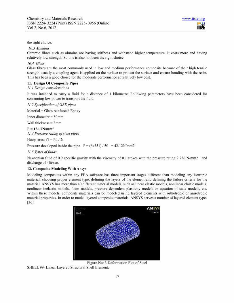
12. Composite Modeling With Ansys
Modeling composites within any FEA software has three important stages different than modeling any isotropic
material: choosing proper element type, defining the layers of the element and defining the failure criteria for the
material .ANSYS has more than 40 different material models, such as linear elastic models, nonlinear elastic models,
nonlinear inelastic models, foam models, pressure dependent plasticity models or equation of state models, etc.
Within these models, composite materials can be modeled using layered elements with orthotropic or anisotropic
material properties. In order to model layered composite materials; ANSYS serves a number of layered element types
[36]:
Figure No: 3 Deformation Plot of Steel
SHELL 99- Linear Layered Structural Shell Element,

Chemistry and Materials Research www.iiste.org
ISSN 2224- 3224 (Print) ISSN 2225- 0956 (Online)
Vol 2, No.6, 2012
18
SHELL 91 - Nonlinear Layered Structural Shell Element,
SHELL 181 - Finite Strain Shell,
SOLID 46- 3-D Layered Structural Solid Element,
SOLID 191- Layered Structural Solid Element,
In addition, SOLID 95, SHELL 63 and SOLID 65 elements can also be used for composite modeling with some key
options; basically for single layers or for approximate calculations. The type of element to be used in the model
depends on the specific application, and the results that are needed at the end of the analysis. As a rule in finite
element analysis technique: if one dimension of the model is 10 or more time greater than the other two, shell
elements should be preferred instead of solid38 elements. If two dimension of the model is 10 or more times greater
than the other one, beam elements should be preferred [36].Shell elements can be imagined as collapsed solid
elements, which have negligible through thickness stress values. Since some edges are absent in shell elements,
generally more degrees of freedom (rotational degrees of freedom) are defined for nodes of a shell element.
For our specific application, solid elements should not be used due to geometrical considerations. SHELL 91 is not
preferred either, since it is used with nonlinear applications such as large strain, sandwich construction or plasticity.
SHELL 181 is not preferred since highly nonlinear behavior exists. Layered configuration can be modeled by
specifying the layer properties; such as material properties, orientation angle, layer thickness and number of
integration points per layer. For SOLID 46 and SHELL 99 element types of ANSYS, constitutive matrices can be
defined with an ‘infinite number of layers’ opportunity.
Fig no:- 4 VONMISES STRESS.:- Stress analysis of a steel pipe
Within Layered configuration, SHELL 63, SHELL 91, SHELL 181 and SHELL 63 elements of ANSYS permit
sandwich construction using one layer and real constants. It is possible to model ply drop-off, by using SHELL 181,
SHELL 91 and SHELL 99elements, by the method of node offsetting. ANSYS permits to use three different failure
criterions for composites: Maximum Strain Failure Criterion, Maximum Stress Failure Criterion and Tsai-Wu Failure
Criterion. Within these models, failure strains, failure stresses and coupling.
Coefficients in all directions of orthotropic or anisotropy can be modeled as temperature dependent
parameter.39ANSYS Parametric Design Language can be used in analyzing a composite structure. See ‘Section 2.3’
for details on APDL.For an application, it should be decided whether which element type or material model to use.
Then the layered configuration should be defined. Layer orientation and orthotropic properties should be checked.
Before running the analysis, failure criteria should be chosen.
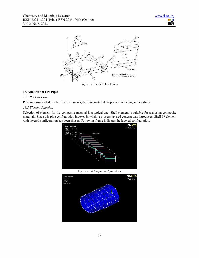
12.1 Shell 99 Elements
Shell 99 is an eight node Linear Layered Structural Shell Element, which can be used to model composite structures
up to 250 layers. Beyond this value, using a user-input constitutive matrix, more than 250 layers can be modeled. It
does not support some nonlinear properties that SHELL 91 supports, but it has smaller computational time .Shell 99
has eight nodes: four corner nodes and four midside nodes. Each node has six degrees of freedom: translations in
three directions and rotation about three axes. An average or each corner thickness can be defined explicitly, which
gives a bilinear varying thickness over the area of the layer, with the thickness input at the corner node locations.
Chemistry and Materials Research www.iiste.org
ISSN 2224- 3224 (Print) ISSN 2225- 0956 (Online)
Vol 2, No.6, 2012
19
Figure no 5:-shell 99 element
13. Analysis Of Gre Pipes
13.1 Pre Processor
Pre-processor includes selection of elements, defining material properties, modeling and meshing.
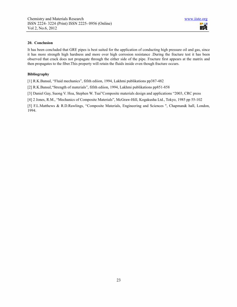
13.2 Element Selection
Selection of element for the composite material is a typical one. Shell element is suitable for analysing composite
materials. Since this pipe configuration invoves in winding process layered concept was introduced. Shell 99 element
with layered configuration has been chosen. Following figure indicates the layered configuration.
Figure no 6: Layer configurations

Chemistry and Materials Research www.iiste.org
ISSN 2224- 3224 (Print) ISSN 2225- 0956 (Online)
Vol 2, No.6, 2012
20
Figure no 7: Deformation plot of steel and GRE
Discussion Of Analysis Result
Analysis result
S.no Material Deformation
mm
Stress
N/mm2
Stiffness
GPa
Tensile
strength
N/mm2
1. GRE 1.72 335 10 1140
2. STEEL 0.017 51 204 351
From the deformation plot and the stress plot it has been found that GR attains comparatively high deformation
because of its low stiffness and comparatively high stress developed but it is well below its strength. It has been
found in the vonmises plot that various red zone were scattered in steel but there was no trace of red zone in GRE
stress plot.
14. Scheme Of Filament Winding Techniques
14.1 General lay out
General lay out has been shown in the figure where it consists of filament winder, Resin tank Guide, Resin and
mandrel. Fiber is being wound and impregnated on the resin through the guide and wound on the mandrel.
For the preparing the pipe for the As stated earlier reinforcement material used here is Glass fiber in the form of
roving. Resin used here is Epoxy has been kept separately in the resin tank.Roving bundle was carefully mounted on
the winding set up.

Chemistry and Materials Research www.iiste.org
ISSN 2224- 3224 (Print) ISSN 2225- 0956 (Online)
Vol 2, No.6, 2012
21
15. Manufacturing Process
15.1 Mandrel Preparation
Outer surface of the mandrel has-been cleaned thoroughly using Diesel and ensured from free of rust. In case of Mild
steel demold has-been applied on the outer surface of the mandrel to facilitate easy removal of the part. In case of
PVC Pipe has been Split into two half and fastened together by bolt to ensure easy removal of the part here applying
demold is not necessary.
15.2 Filament preparation
Resin tank must be completely cleaned before pouring of resin into the tank. Prior to pouring of resin, Fibre tape
must be fixed with the winder and as well as on the Guide .Proper tension must be maintained between the mandrel
and resin tank to facilitate the proper winding into the mandrel.
15.3 Resin preparation
A 1 litre of epoxy solution is measured using measuring jar and poured at the resin tank. Then the 100ml of TETA
solution is measured using the measuring jar poured to the resin tank. Then the mixture of both the epoxy and TETA
are stirred well using the stirrer. Since pot life of the hardener is 30 min the process has to be carried out as soon as
possible. Care must be taken while mixing resin and hardener. If hardener to resin ratio exceeds 1:10 blend will
completely solidified. If ratio is less than 1:10 curing will get delayed.
15.4 Winding process
Before start winding care must be taken on the resin for its viscosity and tension of the fibre tape must be tested.
After starting the machine carriage must be moved with prescribed feed rate and the angle. Winding must be stopped
when desired thickness is achieved so that 3 mm.
15.5 Curing process
Curing is the process to dense the pipe with the desired hardness can be done by two processes open and oven curing.
15.6 Open curing
Curing can be affected by temperature and the pressure. If Curing is done at atmospheric temperature and pressure
then it can be termed as open curing .Wound pipe let into atmospheric cooling for two hours or more. TETA
facilitates the open curing at the atmospheric temperature.DDM can also be used in the curing process where it
should be heated at 200 o c to liquefy the hardener and then it needed to be mixed with the resin.
15.7 Oven curing
Following fig shows the curing cycle of the Epoxy resin in turn applied for the GRE pipes In oven curing Wound
pipe must be kept at the heating oven or furnace at around 200 ͦ c and allow it to cool at the atmospheric temperature.
It will give the better result.
15.8 Curing cycle
Filament winding

Chemistry and Materials Research www.iiste.org
ISSN 2224- 3224 (Print) ISSN 2225- 0956 (Online)
Vol 2, No.6, 2012
22
18. Results And Comparison
18.1Comparative Statement
Description PVC GI GRE
Hardness
number 60 HRK 80 HRC 62HRC
Ultimate Load 0.2KN 10HRC 9HRC
Leak status No trace No trace No trace
18.2 Compressive Test (ASTM D 695)
Apparatus required
• Compressive testing machine
• Specimen
Specimen:-Specification of the specimen
Internal diameter : Φ50mm
Wall thickness : 3mm
Length of the pipe : 150mm
18.3 Testing procedure
1. First specimen is placed laterally on the compressive testing machine table.
2. Dials are initially set to zero.
3. Hydraulic upper jaw is slowly let it contact with the surface of the specimen.
4. Load is being applied to the specimen.
19. Testing Procedure
Specimens opened bottom end is closed by means of the clamp and poured with the hydraulic oil top end also closed
with the clamp and it has been kept for a period of one month and observation on any leak has been noted.
Name of the test Hardness test Compressive test Leak test
Test result 62 HRC 9KN No Trace of
leak found
Chemistry and Materials Research www.iiste.org
ISSN 2224- 3224 (Print) ISSN 2225- 0956 (Online)
Vol 2, No.6, 2012
23
20. Conclusion
It has been concluded that GRE pipes is best suited for the application of conducting high pressure oil and gas, since
it has more strength high hardness and more over high corrosion resistance .During the fracture test it has been
observed that crack does not propagate through the either side of the pipe. Fracture first appears at the matrix and
then propagates to the fiber.This property will retain the fluids inside even though fracture occurs.
Bibliography
[1] R.K.Bansal, “Fluid mechanics”, fifith ediion, 1994, Lakhmi publikations pp387-482
[2] R.K.Bansal,“Strength of materials”, fifith ediion, 1994, Lakhmi publikations pp851-858
[3] Daniel Gay, Suong V. Hoa, Stephen W. Tsai”Composite materials design and applications “2003, CRC press
[4] 2 Jones, R.M., “Mechanics of Composite Materials”, McGraw-Hill, Kogakusha Ltd., Tokyo, 1985 pp 55-102
[5] F.L.Matthews & R.D.Rawlings, “Composite Materials, Engineering and Sciences ", Chapman& hall, London,
1994.

This academic article was published by The International Institute for Science,
Technology and Education (IISTE). The IISTE is a pioneer in the Open Access
Publishing service based in the U.S. and Europe. The aim of the institute is
Accelerating Global Knowledge Sharing.
More information about the publisher can be found in the IISTE’s homepage:
http://www.iiste.org
CALL FOR PAPERS
The IISTE is currently hosting more than 30 peer-reviewed academic journals and
collaborating with academic institutions around the world. There’s no deadline for
submission. Prospective authors of IISTE journals can find the submission
instruction on the following page: http://www.iiste.org/Journals/
The IISTE editorial team promises to the review and publish all the qualified
submissions in a fast manner. All the journals articles are available online to the
readers all over the world without financial, legal, or technical barriers other than
those inseparable from gaining access to the internet itself. Printed version of the
journals is also available upon request of readers and authors.
IISTE Knowledge Sharing Partners
EBSCO, Index Copernicus, Ulrich's Periodicals Directory, JournalTOCS, PKP Open
Archives Harvester, Bielefeld Academic Search Engine, Elektronische
Zeitschriftenbibliothek EZB, Open J-Gate, OCLC WorldCat, Universe Digtial
Library , NewJour, Google Scholar
Related Documents