INTERNATIONAL JOURNAL OF PROFESSIONAL ENGINEERING STUDIES Volume VI /Issue 1 / DEC 2015 IJPRES ANALYSIS OF FUZZY CONTROLLED SHUNT AND SERIES FACTS WITH LOAD VOLTAGE CONTROL IN DISTRIBUTION SYSTEM V.SRAVANTHI M.TECH(Electrical Power System) CVSR college of Engineering, Rangareddy. S.SARASWATHI (PG) Associate Professor CVSR college of Engineering, Rangareddy. Abstract-In this paper, a distribution static compensator (DSTATCOM) as a shunt device and a dynamic voltage restorer (DVR) as a series device are considered in the voltage-control mode for the comparison. The advantage of fuzzy control is that it is based on a linguistic description and does not require a mathematical model of the system and it can adapt its gain according to the changes in load. The instantaneous p-q theory is used for calculating the compensating current. Fuzzy-adaptive hysteresis band technique is adopted for the current control to derive the switching signals for the voltage source inverter. A fuzzy logic-based controller is developed to control the voltage of the DC Capacitor. This work presents and compares the performance of the fuzzy- adaptive controller with a conventional fuzzy and PI controller under constant load. The total Harmonic Distortion, Individual harmonic content with respect to % of fundamental in Supply current, source voltage have been analyzed. The power-quality problems which these compensator address include voltage sags/swells, load voltage harmonic distortions, and unbalancing. The effect of various system parameters on the control performance of the compensator can be studied using the proposed analysis. In particular, the performances of the two compensators are compared with the strong ac supply (stiff source) and weak ac-supply (non-stiff source) distribution system. The experimental verification of the analytical results derived has been obtained using a laboratory model of the single-phase DSTATCOM and DVR. Simulation studies have been performed in the PSCAD/EMTDC software to verify the results in the three- phase system. Index Terms—Distribution static compensator(DSTATCOM),dynamic voltage restorer (DVR),frequency-response characteristic,load voltage control, multilevel inverter, nonlinear load, Fuzzy logic controller. I.INTRODUCTION The input variables in a fuzzy control system are in general mapped by sets of membership functions similar to this, known as "fuzzy sets". The process of converting a crisp input value to a fuzzy value is called "fuzzification". A control system may also have various types of switch, or "ON-OFF", inputs along with its analog inputs, and such switch inputs of course will always have a truth value equal to either 1 or 0, but the scheme can deal with them as simplified fuzzy functions that happen to be either one value or another. The voltage related power-quality (PQ) problems, such as sags and swells, voltage dips, harmonic distortions due to nonlinear loads and voltage unbalancing in electrical power distribution systems, have been a major concern for the voltage-sensitive loads. Load voltage regulation using VSC for different grid-connected applications has been recently attempted. Power quality is becoming important due toproliferation of nonlinear loads, such as rectifier equipment, adjustable speed drives, domestic appliances and arc furnaces. These nonlinear loads draw non-sinusoidal currents from ac mains and cause a type of current and voltage distortion called as ‘harmonics’. These harmonics causes various problems in power systems and in consumer products such as equipment overheating, capacitor blowing, motor vibration, transformer over heating excessive neutral currents and low power factor. Power quality problems are common in most of commercial, industrial and utility networks. Natural phenomena, such as lightning are the most frequent cause of power quality problems. Switching phenomena resulting in oscillatory transients in the electrical supply. For all these reasons, from the consumer point of view, power quality issues will become an increasingly important factor to consider in order to satisfy good productivity. To address the needs of energy consumers trying to improve productivity through the reduction of power quality related process stoppages and energy suppliers trying to maximize operating profits while keeping customers satisfied with supply quality, innovative technology provides the key to cost-effective power quality enhancements solutions. Two types of VSC-based compensators have been commonly used for mitigation of the voltage sags and swells and regulating the load bus voltage. The first one is a shunt device, which is commonly called DSTATCOM, and the second one is a series device, which is commonly called DVR. In, these compensators can address other PQ issues, such as load voltage

Welcome message from author
This document is posted to help you gain knowledge. Please leave a comment to let me know what you think about it! Share it to your friends and learn new things together.
Transcript

INTERNATIONAL JOURNAL OF PROFESSIONAL ENGINEERING STUDIES Volume VI /Issue 1 / DEC 2015
IJPRES
ANALYSIS OF FUZZY CONTROLLED SHUNT AND SERIES FACTS WITH LOAD VOLTAGE CONTROL IN DISTRIBUTION
SYSTEM
V.SRAVANTHI M.TECH(Electrical Power System)
CVSR college of Engineering, Rangareddy.
S.SARASWATHI
(PG) Associate Professor CVSR college of Engineering,
Rangareddy.
Abstract-In this paper, a distribution static compensator (DSTATCOM) as a shunt device and a dynamic voltage restorer (DVR) as a series device are considered in the voltage-control mode for the comparison. The advantage of fuzzy control is that it is based on a linguistic description and does not require a mathematical model of the system and it can adapt its gain according to the changes in load. The instantaneous p-q theory is used for calculating the compensating current. Fuzzy-adaptive hysteresis band technique is adopted for the current control to derive the switching signals for the voltage source inverter. A fuzzy logic-based controller is developed to control the voltage of the DC Capacitor. This work presents and compares the performance of the fuzzy-adaptive controller with a conventional fuzzy and PI controller under constant load. The total Harmonic Distortion, Individual harmonic content with respect to % of fundamental in Supply current, source voltage have been analyzed. The power-quality problems which these compensator address include voltage sags/swells, load voltage harmonic distortions, and unbalancing. The effect of various system parameters on the control performance of the compensator can be studied using the proposed analysis. In particular, the performances of the two compensators are compared with the strong ac supply (stiff source) and weak ac-supply (non-stiff source) distribution system. The experimental verification of the analytical results derived has been obtained using a laboratory model of the single-phase DSTATCOM and DVR. Simulation studies have been performed in the PSCAD/EMTDC software to verify the results in the three-phase system.
Index Terms—Distribution static compensator(DSTATCOM),dynamic voltage restorer (DVR),frequency-response characteristic,load voltage control, multilevel inverter, nonlinear load, Fuzzy logic controller.
I.INTRODUCTION The input variables in a fuzzy control system
are in general mapped by sets of membership functions similar to this, known as "fuzzy sets". The process of converting a crisp input value to a fuzzy value is called "fuzzification".
A control system may also have various types of switch, or "ON-OFF", inputs along with its analog
inputs, and such switch inputs of course will always have a truth value equal to either 1 or 0, but the scheme can deal with them as simplified fuzzy functions that happen to be either one value or another.
The voltage related power-quality (PQ) problems, such as sags and swells, voltage dips, harmonic distortions due to nonlinear loads and voltage unbalancing in electrical power distribution systems, have been a major concern for the voltage-sensitive loads. Load voltage regulation using VSC for different grid-connected applications has been recently attempted. Power quality is becoming important due toproliferation of nonlinear loads, such as rectifier equipment, adjustable speed drives, domestic appliances and arc furnaces. These nonlinear loads draw non-sinusoidal currents from ac mains and cause a type of current and voltage distortion called as ‘harmonics’. These harmonics causes various problems in power systems and in consumer products such as equipment overheating, capacitor blowing, motor vibration, transformer over heating excessive neutral currents and low power factor. Power quality problems are common in most of commercial, industrial and utility networks. Natural phenomena, such as lightning are the most frequent cause of power quality problems. Switching phenomena resulting in oscillatory transients in the electrical supply. For all these reasons, from the consumer point of view, power quality issues will become an increasingly important factor to consider in order to satisfy good productivity. To address the needs of energy consumers trying to improve productivity through the reduction of power quality related process stoppages and energy suppliers trying to maximize operating profits while keeping customers satisfied with supply quality, innovative technology provides the key to cost-effective power quality enhancements solutions.
Two types of VSC-based compensators have been commonly used for mitigation of the voltage sags and swells and regulating the load bus voltage. The first one is a shunt device, which is commonly called DSTATCOM, and the second one is a series device, which is commonly called DVR. In, these compensators can address other PQ issues, such as load voltage
Gurmeet
Typewritten Text
264
INTERNATIONAL JOURNAL OF PROFESSIONAL ENGINEERING STUDIES Volume VI /Issue 1 / DEC 2015
IJPRES
harmonics, source current harmonics, unbalancing, etc., under steady state to obtain more benefits out of their continuous operation.
In spite of the appearance there are several difficulties to give a rigorous logical interpretation of the IF-THEN rules. As an example, interpret a rule as IF (temperature is "cold") THEN (heater is "high") by the first order formula Cold(x)→High(y) and assume that r is an input such that Cold(r) is false. Then the formula Cold(r)→High(t) is true for any t and therefore any t gives a correct control given r. A rigorous logical justification of fuzzy control is given in Hájek's book (see Chapter 7) where fuzzy control is represented as a theory of Hájek's basic logic. Also in Gerla 2005 a logical approach to fuzzy control is proposed based on fuzzy logic programming. Indeed, denote by f the fuzzy function arising of an IF-THEN system of rules. Then we can translate this system into a fuzzy program P containing a series of rules whose head is "Good(x,y)". The interpretation of this predicate in the least fuzzy Her brand model of P coincides with f. This gives further useful tools to fuzzy control.
II. VSC-BASED SHUNT AND SERIES COMPENSATORS
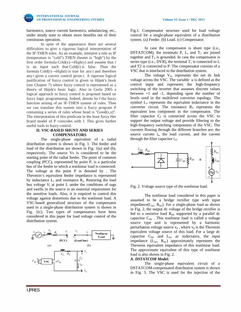
The single-phase equivalent of a radial distribution system is shown in Fig. 1. The feeder and load of the distribution are shown in Fig. 1(a) and (b), respectively. The source Vs is considered to be the starting point of the radial feeder. The point of common coupling (PCC), represented by point P, is a particular bus of the feeder to which a nonlinear load is connected. The voltage at the point P is denoted by . The Thevenin’s equivalent feeder impedance is represented by inductance Ls and resistance Rs. Restoring the load bus voltage Vl at point L under the conditions of sags and swells in the source is an essential requirement for the sensitive loads. Also, it is required to control this voltage against distortions due to the nonlinear load. A VSC-based generalized structure of the compensator used in a single-phase distribution system is shown in Fig. 1(c). Two types of compensators have been considered in this paper for load voltage control of the distribution system.
Fig.1. Compensator structure used for load voltage control for a single-phase equivalent of a distribution system. (a) Feeder. (b) Load. (c) Compensator.
In case the compensator is shunt type (i.e., DSTATCOM), the terminals P, L, and T1 are joined together and T2 is grounded. In case the compensator is series type (i.e., DVR), the terminal T1 is connected to L and T2 is connected to P. The compensator consists of a VSC that is interfaced to the distribution system.
The voltage Vdc represents the net dc link voltage across the VSC. The variable u is defined as the control input and represents the high-frequency switching of the inverter that assumes discrete values between +1 and -1, depending upon the number of levels used in the multilevel converter topology. The symbol LT represents the equivalent inductance in the converter circuit. The resistance RT represents the equivalent loss component in the compensator. The filter capacitor Cf is connected across the VSC to support the output voltage and provide filtering to the high-frequency switching components of the VSC. The currents flowing through the different branches are: the source current is, the load current, and the current through the filter capacitor icf.
Fig. 2. Voltage source type of the nonlinear load.
The nonlinear load considered in this paper is assumed to be a bridge rectifier type with input impedance(Llac, Rlac). For a single-phase load as shown in Fig. 2, the output dc voltage of the bridge rectifier is fed to a resistive load Rldc supported by a parallel dc capacitor Cldc . This nonlinear load is called a voltage source type and is represented by a harmonic perturbation voltage source vd , where vd is the Thevenin equivalent voltage source of this load. For a large dc capacitor Cldc and Llac ac inductance, the input impedance (Llac, Rlac) approximately represents the Thevenin equivalent impedance of this nonlinear load. The approximate equivalent of this type of nonlinear load is also shown in Fig. 2. A. DSTATCOM Model:
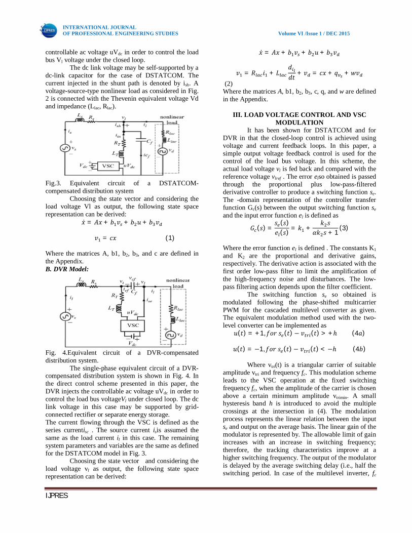
The single-phase equivalent circuit of a DSTATCOM-compensated distribution system is shown in Fig. 3. The VSC is used for the injection of the
Gurmeet
Typewritten Text
Gurmeet
Typewritten Text
265
INTERNATIONAL JOURNAL OF PROFESSIONAL ENGINEERING STUDIES Volume VI /Issue 1 / DEC 2015
IJPRES
controllable ac voltage uVdc in order to control the load bus Vl voltage under the closed loop.
The dc link voltage may be self-supported by a dc-link capacitor for the case of DSTATCOM. The current injected in the shunt path is denoted by ish. A voltage-source-type nonlinear load as considered in Fig. 2 is connected with the Thevenin equivalent voltage Vd and impedance (Llac, Rlac).
Fig.3. Equivalent circuit of a DSTATCOM-compensated distribution system
Choosing the state vector and considering the load voltage Vl as output, the following state space representation can be derived:
푥̇ = 퐴푥 + 푏 푣 + 푏 푢 + 푏 푣
푣 = 푐푥 (1)
Where the matrices A, b1, b2, b3, and c are defined in the Appendix. B. DVR Model:
Fig. 4.Equivalent circuit of a DVR-compensated distribution system.
The single-phase equivalent circuit of a DVR-compensated distribution system is shown in Fig. 4. In the direct control scheme presented in this paper, the DVR injects the controllable ac voltage uVdc in order to control the load bus voltageVl under closed loop. The dc link voltage in this case may be supported by grid-connected rectifier or separate energy storage. The current flowing through the VSC is defined as the series currentisc . The source current isis assumed the same as the load current il in this case. The remaining system parameters and variables are the same as defined for the DSTATCOM model in Fig. 3.
Choosing the state vector and considering the load voltage vl as output, the following state space representation can be derived:
푥̇ = 퐴푥 + 푏 푣 + 푏 푢 + 푏 푣
푣 = 푅 푖 + 퐿푑푑푡 + 푣 = 푐푥 + 푞 +푤푣
(2) Where the matrices A, b1, b2, b3, c, q, and w are defined in the Appendix.
III. LOAD VOLTAGE CONTROL AND VSC MODULATION
It has been shown for DSTATCOM and for DVR in that the closed-loop control is achieved using voltage and current feedback loops. In this paper, a simple output voltage feedback control is used for the control of the load bus voltage. In this scheme, the actual load voltage vl is fed back and compared with the reference voltage vlref . The error elso obtained is passed through the proportional plus low-pass-filtered derivative controller to produce a switching function se. The -domain representation of the controller transfer function Gc(s) between the output switching function se and the input error function el is defined as
퐺 (푠) =푠 (푠)푒 (푠) = 푘 +
푘 푠훼푘 푠 + 1
(3)
Where the error function el is defined . The constants K1 and K2 are the proportional and derivative gains, respectively. The derivative action is associated with the first order low-pass filter to limit the amplification of the high-frequency noise and disturbances. The low-pass filtering action depends upon the filter coefficient.
The switching function se so obtained is modulated following the phase-shifted multicarrier PWM for the cascaded multilevel converter as given. The equivalent modulation method used with the two-level converter can be implemented as
푢(푡) = +1,푓표푟 푠 (푡) − 푣 (푡) > +ℎ (4푎)
푢(푡) = −1,푓표푟 푠 (푡)− 푣 (푡) < −ℎ (4푏)
Where vtri(t) is a triangular carrier of suitable amplitude vtri and frequency fc. This modulation scheme leads to the VSC operation at the fixed switching frequency fc, when the amplitude of the carrier is chosen above a certain minimum amplitude vtrimin. A small hysteresis band h is introduced to avoid the multiple crossings at the intersection in (4). The modulation process represents the linear relation between the input se and output on the average basis. The linear gain of the modulator is represented by. The allowable limit of gain increases with an increase in switching frequency; therefore, the tracking characteristics improve at a higher switching frequency. The output of the modulator is delayed by the average switching delay (i.e., half the switching period. In case of the multilevel inverter, fc
Gurmeet
Typewritten Text
Gurmeet
Typewritten Text
266
INTERNATIONAL JOURNAL OF PROFESSIONAL ENGINEERING STUDIES Volume VI /Issue 1 / DEC 2015
IJPRES
represents the effective switching frequency. The effect of the high-frequency switching due to modulation is modeled as a first-order lag. Therefore, in steady state, the modulation process is defined by a transfer function Gd(s) that consists of a fixed gain Kd and a delay function as
퐺 (푠) =푘
(1 + 푇 푠). (5)
The complete block diagram of the load voltage control using either DSTATCOM or DVR is shown in Fig. 5.
Fig.5. Block diagram of the load voltage control using DSTATCOM or DVR.
The following transfer functions in Fig. 5 can be derived from (1) or (2) for the case of DSTATCOM or DVR, respectively
퐺 (푠) =푣 (푠)푢(푠)
푐(푠퐼 − 퐴) 푏 (6)
퐺 (푠) =푣 (푠)푣 (푠) = 푐(푠퐼 − 퐴) 푏 + 푞 (7)
퐺 (푠) =푣 (푠)푣 (푠) = 푐(푠퐼 − 퐴) 푏 + 휔 (8)
Note that the matrices q and w in (7) and (8), respectively, are null matrices for the case of DSTATCOM.
IV. TRACKING CHARACTERISTICS USING STEADY-STATE FREQUENCY-RESPONSE
ANALYSIS In this section, the steady-state tracking
behavior of the load voltage control using DSTATCOM and DVR are discussed. Comparisons of the tracking characteristics of the two compensating devices are made with reference to the weak and strong ac supply system. A. Weak AC Supply System
Assume a weak (or non-stiff) ac supply system. Consider the per unit system parameters of such a weak ac supply system given in Table I.
TABLE I PER UNIT SYSTEM PARAMETERS
1) DSTATCOM: Let us first study the tracking characteristics of load bus voltage control using DSTATCOM. The transfer functions are determined using (6)–(8), respectively. The state space model of DSTATCOM given in (1) is used for obtaining the transfer functions. Under the ideal tracking condition in (4) (i.e., high gain and zero delay in (5) corresponding to infinite switching frequency, and ideal derivative action in (3), that is the dominant closed-loop pole will lie close to for the closed-loop system shown in Fig. 5. Therefore, the system dynamics will be governed by the time constant. However, with practical switching devices(e.g., insulated-gate bipolar transistors (IGBTs) operating atthe finite fixed switching frequency), the modulator dynamics(5) are used in Fig. 5. In this situation, the system will havesatisfactory stability properties with (i.e., poleto the left of zero). Now consider a unity gain modulator and the delay corresponding to 2 kHz of the effectiveswitching frequency of the inverter (i.e., 0.25 ms. Thetransfer functionis determined by using (5). In orderto determine the controller transfer function from (3),let us consider the following parameters: and K2= 0.001 for T= 0.33 ms, which also satisfies the aforementionedCondition . The value of filter coefficientis chosen as 0.01 in (3) for better filtering of high-frequencynoise. Fig. 6 shows the closed-loop frequency response of theoutput load voltage vlwith respect to the reference voltage vlreffor the aforementioned data.
A comparison is also madein Fig. 6 when the modulator transfer function has changed,corresponding to the high gain (e.g., Kd= 5) and high effective switching frequency (e.g., 3 kHz), with Td= 0.1667 ms in (5). The stability properties further improves based on the condition. The rest of the parameter is considered the same as before. It is clear from the figure that the tracking characteristics for the low-frequency references (e.g., 50 Hz) would be better and bandwidth would be higher (better stability) with the high effective switching frequency and higher gain modulator. Though there is also an increased resonant peak as seen from Fig. 6, however, sufficiently higher bandwidth ensures better transient performance under closed loop. Therefore, it is
Gurmeet
Typewritten Text
267

INTERNATIONAL JOURNAL OF PROFESSIONAL ENGINEERING STUDIES Volume VI /Issue 1 / DEC 2015
IJPRES
desirable to use high effective switching frequency with high modulator gain for better tracking characteristics. Here onwards, these higher values would be considered for the theoretical analysis in this paper.
Fig. 6. Comparison of the closed-loop frequency response of DSTATCOM with respect to the reference load voltage Vlref for two different modulator dynamics: (first) low gain and low effective switching frequency and (second) high gain and high effective switching frequency, for a weak ac supply system.
Fig. 7. Closed-loop frequency response of the DSTATCOM with respect tothe source voltage vs and nonlinear load perturbation voltage vd for a weak ac supply system.
Fig. 7 shows the closed-loop frequency response with respect to the source voltage Vsand nonlinear load perturbation voltage Vd . These plots are obtained with respect to the block diagram shown in Fig. 5 and using the transfer functions and , obtained from (7) and (8), respectively. The DSTATCOM provides good attenuation with respect to both of these perturbations over a wide range of frequencies. 2) DVR:
Consider now study of the tracking characteristics of the load bus voltage control using DVR for a weak ac supply system. The transfer functions and for the case of DVR is determined using (6)–(8), respectively. The state space model of DVR
given in (2) is used for obtaining these transfer functions. Fig. 8 shows the closed-loop frequency response of the output load voltage vlwith respect to the reference voltage vlref for the same data as considered for the DSTATCOM earlier. The effective switching frequency and gain for the modulator (5) are considered high as for the case of the DSTATCOM. It can be seen from Fig. 8 that the tracking characteristic with the DVR is similar to that of the DSTATCOM shown in Fig. 6. However, the bandwidth of the control loop in case of DVR is reduced considerably compared to that with DSTATCOM
Fig. 8. Closed-loop frequency response of DVR with respect to the reference load voltage vlref for a weak ac supply system.
Fig. 9 shows the closed-loop frequency response with respect to the source voltage Vs and nonlinear perturbation voltage Vd. It is clear from Fig. 9 that with respect to both of these variables, the attenuation decreases at higher frequencies and perturbations passes almost without any attenuation above the bandwidth of the control loop. The DVR can control the load voltage against sags and swells in the source voltage since it provides sufficient attenuation to these low-frequency disturbances in the source voltage.
However, as seen in Fig. 9, the presence of high-frequency components in the nonlinear load will appear in the load voltage without any attenuation. Therefore, notches may be present in the load voltage when the load is nonlinear and the feeder is non-stiff, in case of compensation with the DVR.
Gurmeet
Typewritten Text
268

INTERNATIONAL JOURNAL OF PROFESSIONAL ENGINEERING STUDIES Volume VI /Issue 1 / DEC 2015
IJPRES
Fig. 9. Closed-loop frequency response of DVR with respect to the source voltage vs and nonlinear load perturbation voltage vd for a weak ac supply system. B. Strong AC Supply System:
Assume a strong (or stiff) ac supply system. Consider the same per unit system parameters as given in Table I, except that the per unit feeder impedance is 1/100 or the feeder short-circuit capacity is 100 times that for the case of the weak ac system considered in the previous subsection. Fig. 10 shows the comparison of the closed-loop frequency response of the load voltage control for the DSTATCOM and the DVR, with respect to the reference load voltage. It is clear from the figure that for the case of stiff source, the DSTATCOM has inferior tracking properties and, therefore, cannot control the load voltage, whereas the DVR is effective for the load voltage control in this case. Fig. 11 shows the comparison of the closed-loop frequency response for the DSTATCOM and the DVR with respect to the source voltage and nonlinear load perturbation voltage.
It is seen from the figure that attenuation for the DSTATCOM with respect to the source voltage is negligible and, therefore, it is ineffective for sags and swells compensation in this case. The DVR has good attenuation against source voltage and nonlinear load perturbation voltage. Therefore, the DVR is the better option for the load voltage-control application in case of the stiff source. Remark 1:Based upon the closed-loop frequency-response analysis, the following text has been observed for the compensators and its control method proposed in this paper with different values of feeder resistance Rs and feeder reactance. For DSTATCOM, the tracking characteristic largely depends upon the net feeder impedance and it deteriorates at low impedance (strong ac supply system). In particular, low feeder reactance deteriorates attenuation to the harmonic components in source voltage and low feeder resistance deteriorates the capability of DSTATCOM to control the load voltage against sags and swells. For DVR, the tracking characteristic deteriorates at high feeder impedance (weak ac supply system). In this case, high feeder resistance deteriorates load voltage regulation capability of the DVR and high feeder reactance deteriorates compensation against high-frequency components of the nonlinear load.
V. FUZZY LOGIC CONTROLLER Based on the nature of fuzzy human thinking,
Lotfi Zadeh, a computer scientist at the University of California, Berkeley, originated the “fuzzy logic,” or fuzzy set theory, in 1965.The general methodology of reasoning in FL and ES by “IF…….THEN…..” statements or rules is the same; it is often called “ fuzzy expert system.” The design of a conventional control system is normally based on the mathematical model of a plant. If an accurate mathematical model is available
with known parameters, it can be analyzed. Fuzzy control, on the other hand, does not strictly need any mathematical model of the plant.
Fig.10.Fuzzy logic controller
Fuzzification: The fuzzy logic controller requires that each input/output variable which define the control surface be expressed in fuzzy set notations using linguistic levels. The linguistic values of each input and output variables divide its universe of discourse into adjacent intervals to form the membership functions. The member value denotes the extent to which a variable belong to a particular level. The process of converting input/output variable to linguistic levels is termed as fuzzification.
Interference Method:
The behaviour of the control surface which relates the input and output variables of the system is governed by a set of rules. A typical rule would be If x is A Then y is B When a set of input variables are read each of the rule that has any degree of truth in its premise is fired and contributes to the forming of the control surface by approximately modifying it. When all the rules are fired, the resulting control surface is expressed as a fuzzy set to represent the constraints output. This process is termed as inference. Defuzzification:
Defuzzification is the process of conversion of fuzzy quantity into crisp quantity. There are several methods available for defuzzification. The most prevalent one is centroid method, which utilizes the following formula, where μ is the membership degree of output x. Data Base: The Database stores the definition of the membership function required by fuzzifier and
Gurmeet
Typewritten Text
269
INTERNATIONAL JOURNAL OF PROFESSIONAL ENGINEERING STUDIES Volume VI /Issue 1 / DEC 2015
IJPRES
defuzzifier. Storage format is a compromise between available memory and MIPS of the digital controller chip. Rulebase : The Rulebase stores the linguistic control rules required by rule evaluator (decision making logic).
Applications of Fuzzy Logic Controller: Fuzzy logic has been widely applied in power
electronic systems. Applications include speed control of dc and ac drives, feedback control of converter, off-line P-I and P-I-D tuning, nonlinearity compensation, on-line and off-line diagnostics, modelling, parameter estimation, performance optimization of drive systems based on on-line search, estimation for distorted waves, and so on.
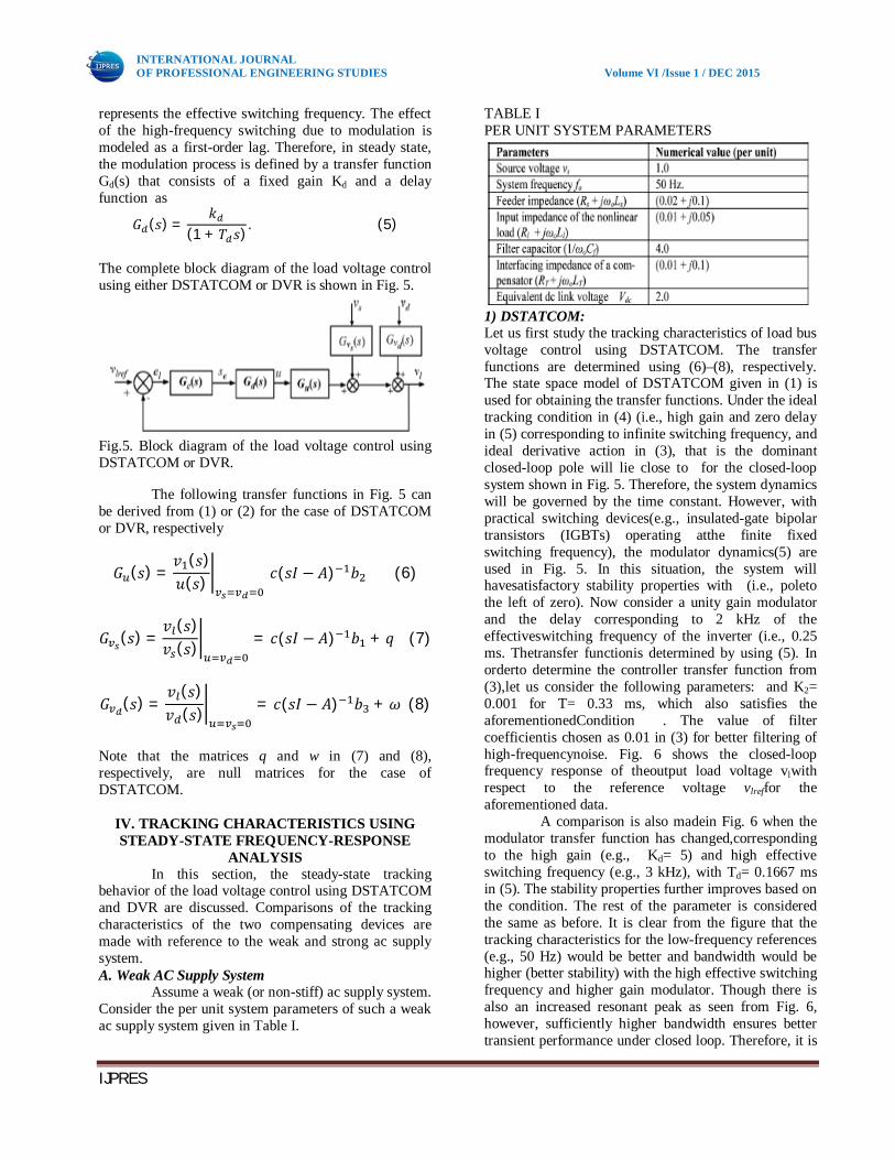
VI. MATLAB CIRCUIT MODEL
In this section, the load voltage of a three-phase four-wire11-kV distribution system is controlled. The convertertopology based on the seven-level cascaded transformer multilevelinverter as proposed in [25] and shown in Fig. 19 has been used for the DSTATCOM and the DVR.
Fig.11.Matlab circuit model
A. Load Voltage Control Using DSTATCOM The feeder parameter as given in Table III shows that thesupply system is weak. Therefore, a DSTATCOM is used hereto control the load voltage. The seven-level multicarrier PWMhas been used with three H-bridges per phase , asshown in Fig. 19. A carrier frequency of 1.0 kHz is considered. B. Load Voltage Control Using DVR To illustrate the performance of DVR, it is assumedthat an industrial load is directly connected to the 11-kV bus sothat the supply system is strong with the feeder impedance ofp.u. The same multilevel converter topologyas shown in Fig. 19 has been used for the DVR.
SIMULATION RESULTS
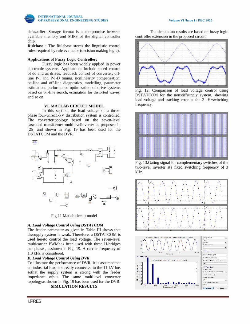
The simulation results are based on fuzzy logic controller extension in the proposed circuit.
Fig. 12. Comparison of load voltage control using DSTATCOM for the nonstiffsupply system, showing load voltage and tracking error at the 2-kHzswitching frequency.
Fig. 13.Gating signal for complementary switches of the two-level inverter ata fixed switching frequency of 3 kHz.
Gurmeet
Typewritten Text
270

INTERNATIONAL JOURNAL OF PROFESSIONAL ENGINEERING STUDIES Volume VI /Issue 1 / DEC 2015
IJPRES
Fig. 14. Load voltage control using DSTATCOM for a non-stiff supply system,showing controlled load voltage and distorted source voltage.
Fig.15. Load voltage control using DSTATCOM for a non-stiff supply system,showing the controlled load voltage and a voltage rise condition of the sourcevoltage.
Fig. 16. Load voltage control using DVR for a non-stiff supply system,showing the controlled load voltage and voltage dip condition of the sourcevoltage.
Fig. 17. Load voltage control using the DVR for a stiff supply system, showingcontrolled load voltage and the voltage dip condition of the source voltage.
Fig. 18. Load voltage control against sag in the source voltage, using DVR forthe stiff supply system.
Gurmeet
Typewritten Text
271

INTERNATIONAL JOURNAL OF PROFESSIONAL ENGINEERING STUDIES Volume VI /Issue 1 / DEC 2015
IJPRES
Fig. 19. Three-phase seven-level cascaded transformer
H-bridge VSC.
(a)
(b)
Fig. 20. (a) Load voltage for three-phase distribution system, DSTATCOM isconnected at 0.2 s. (b) Seven-level inverter output voltages.
(a)
(b)
Fig. 21. Three-phase load voltage control using the DVR against sag and swellin the terminal voltage, the supply is unbalanced with 25% sag from 0.1 to 0.18s and 15% swell from 0.26 to 0.30 s. (a)Terminal voltage (b)Load voltage.
THD Comparison between conventional and Fuzzy logic methods.
Load voltage THD’s Figure Conventional Fuzzy logic
14 & 15 1.72 0.87 16 9.22 3.23 17 3.19 1.59 18 3.34 1.61 20 1.06 0.65 21 1.07 0.64
CONCLUSION
The performance of the VSC-based shunt and series compensators (i.e., DSTATCOM and DVR with the presented topology) along with Fuzzy logic controller instead of using PI controller has been analyzed in voltage control mode through closed-loop
Gurmeet
Typewritten Text
272

INTERNATIONAL JOURNAL OF PROFESSIONAL ENGINEERING STUDIES Volume VI /Issue 1 / DEC 2015
IJPRES
frequency-response characteristics. It is shown that for the weak ac supply system, the load voltage control using DSTATCOM has large bandwidth and good attenuation in source voltage and nonlinear load perturbations. However, the DVR in this case passes high-frequency load components almost unattenuated and causes the presence of notches in the load voltage. For the case of a strong ac supply system, the DVR has good bandwidth and attenuation properties.
The generalized converter topology based on Fuzzy logic controller using multicarrier phase-shifted PWM can be used for the load voltage control of an MV distribution system, following the proposed control algorithm. The results for the three-phase load voltage control have been verified for an 11-kV distribution system, using seven-level cascaded transformer multilevel converter topology, through simulations.
REFERENCES
[1] P. R. Sánchez, E. Acha, J. E. O. Calderon, V. Feliu, and A. G. Cerrada, “A versatile control scheme for a dynamic voltage restorer for power-quality improvement,” IEEE Trans. Power Del., vol. 24, no. 1, pp. 277–284, Jan. 2009. [2] Y. A. R. I. Mohamed and E. F. E. Saadany, “A control method of grid-connected PWM voltage source inverters to mitigate fast voltage disturbances,” IEEE Trans. Power Syst., vol. 24, no. 1, pp. 489–491, Feb. 2009. [3] P. Samuel, R. Gupta, and D. Chandra, “Grid interface of photovoltaic micro turbine hybrid based power for voltage support and control using VSI in rural applications,” presented at the IEEE Power Eng. Soc. Gen. Meeting, Calgary, AB, Canada, 2009. [4] K. Selvajyothi and P. A. Janakiraman, “Reduction of voltage harmonics in single phase inverters using composite observers,” IEEETrans. Power Del., vol. 25, no. 2, pp. 1045–1057, Apr. 2010. [5] A. Ghosh and G. Ledwich, “Load compensating DSTATCOM in weak AC systems,” IEEE Trans. Power Del., vol. 18, no. 4, pp. 1302–1309, Oct. 2003. [6] IEEE Recommended Practices and Requirements for Harmonic Control in Electrical Power Systems, IEEE Std. 519-1992, Apr. 12, 1993. [7] A. Ghosh, “Performance study of two different compensating devices in a custom power park,” Proc. Inst. Elect. Eng., Gen. Transm. Distrib., vol. 152, no. 4, pp. 521–528, Jul. 2005. [8] M. H. Haque, “Compensation of distribution system voltage sag by DVR and D-STATCOM,” in Proc. IEEE Porto Power Tech Conf., Sep. 2001, vol. 1,5, pp. 10–13. [9] G. Ledwich and A. Ghosh, “A flexible DSTATCOM operating in voltage or current control mode,” Proc. Inst. Elect. Eng., Gen.,Transm. Distrib., vol. 149, no. 2, pp. 215–224, Mar. 2002.
[10] M. K. Mishra, A. Ghosh, and A. Joshi, “Operation of a DSTATCOM in voltage control mode,” IEEE Trans. Power Del., vol. 18, no. 1, pp. 258–264, Jan. 2003. [11] R. Gupta and A. Ghosh, “Frequency-domain characterization of sliding mode control of an inverter used in DSTATCOM application,” IEEETrans. Circuits Syst. I, Reg. Papers, vol. 53, no. 3, pp. 662–676, Mar. 2006. [12] B. Singh, A. Adya, A. P. Mittal, J. R. P. Gupta, and B. N. Singh, “Application of DSTATCOM for mitigation of voltage sag for motor loads in isolated distribution systems,” in Proc. IEEE Int. Symp. Ind. Electronics, Jul. 9–13, 2006, vol. 3, pp. 1806–1811.
V.SRAVANTHICompletedB.Tech in Electrical & Electronics Engineering in 2012 from Jayamukhi Institute of Technological Sciences Affiliated to JNTUH, Hyderabad and M.Tech in Electrical Power System in 2015(Perusing) from Anurag Group of Institutions Formly CVSR college of Engineering,Rangareddy. Area of interest includes Power Systems. E-mail id: [email protected]
S.SARASWATHI Presently working as Associate Professor in CVSR college of Engineering, Rangareddy, Telangana India. She received the B.Tech degree in Electrical & Electronics Engineering from JNTUH, Hyderabad in 2006. And then completed her P.G in Electrical & Electronics Engineering as Electrical Power Engineering is specialization at Sreenidhi institute of science and Technology, Hyderabad in 2010 .She has published papers in national and international . E-mail ID:[email protected]
Gurmeet
Typewritten Text
273
Related Documents