Purdue University Purdue e-Pubs Birck and NCN Publications Birck Nanotechnology Center 7-2010 Analysis of evaporating mist flow for enhanced convective heat transfer Niru Kumari Birck Nanotechnology Center and School of Mechanical Engineering, Purdue University, [email protected] Vaibhav Bahadur Purdue University - Main Campus, [email protected] Marc Hodes Tuſts University Todd Salamon Alcatel Lucent, Bell Labs Paul Kolodner Alcatel Lucent, Bell Labs See next page for additional authors Follow this and additional works at: hp://docs.lib.purdue.edu/nanopub Part of the Nanoscience and Nanotechnology Commons is document has been made available through Purdue e-Pubs, a service of the Purdue University Libraries. Please contact [email protected] for additional information. Kumari, Niru; Bahadur, Vaibhav; Hodes, Marc; Salamon, Todd; Kolodner, Paul; Lyons, Alan; and Garimella, S V., "Analysis of evaporating mist flow for enhanced convective heat transfer" (2010). Birck and NCN Publications. Paper 604. hp://docs.lib.purdue.edu/nanopub/604

Welcome message from author
This document is posted to help you gain knowledge. Please leave a comment to let me know what you think about it! Share it to your friends and learn new things together.
Transcript
Purdue UniversityPurdue e-Pubs
Birck and NCN Publications Birck Nanotechnology Center
7-2010
Analysis of evaporating mist flow for enhancedconvective heat transferNiru KumariBirck Nanotechnology Center and School of Mechanical Engineering, Purdue University, [email protected]
Vaibhav BahadurPurdue University - Main Campus, [email protected]
Marc HodesTufts University
Todd SalamonAlcatel Lucent, Bell Labs
Paul KolodnerAlcatel Lucent, Bell Labs
See next page for additional authors
Follow this and additional works at: http://docs.lib.purdue.edu/nanopub
Part of the Nanoscience and Nanotechnology Commons
This document has been made available through Purdue e-Pubs, a service of the Purdue University Libraries. Please contact [email protected] foradditional information.
Kumari, Niru; Bahadur, Vaibhav; Hodes, Marc; Salamon, Todd; Kolodner, Paul; Lyons, Alan; and Garimella, S V., "Analysis ofevaporating mist flow for enhanced convective heat transfer" (2010). Birck and NCN Publications. Paper 604.http://docs.lib.purdue.edu/nanopub/604

AuthorsNiru Kumari, Vaibhav Bahadur, Marc Hodes, Todd Salamon, Paul Kolodner, Alan Lyons, and S V. Garimella
This article is available at Purdue e-Pubs: http://docs.lib.purdue.edu/nanopub/604
Analysis of evaporating mist flow for enhanced convective heat transfer
Niru Kumari a, Vaibhav Bahadur a, Marc Hodes b, Todd Salamon c, Paul Kolodner c, Alan Lyons d,Suresh V Garimella a,*
a School of Mechanical Engineering and Birck Nanotechnology Center, Purdue University, West Lafayette, IN 47907, United Statesb Department of Mechanical Engineering, Tufts University, Medford, MA 02155, United Statesc Bell Laboratories, Alcatel-Lucent, Murray Hill, NJ 07974, United Statesd Department of Chemistry, City University of New York, Staten Island, NY 10314, United States
a r t i c l e i n f o
Article history:Received 6 November 2009Received in revised form 5 February 2010Accepted 5 February 2010Available online 30 March 2010
Keywords:Mist flowTwo-phase flowThermal managementHeat transfer enhancement
a b s t r a c t
Enhancement of forced convective heat transport through the use of evaporating mist flow is investigatedanalytically and by numerical simulation. A two-phase mist, consisting of finely dispersed water dropletsin an airstream, is introduced at the inlet of a longitudinally-finned heat sink. The latent heat absorbed bythe evaporating droplets significantly reduces the sensible heating of the air inside the heat sink whichtranslates into higher heat-dissipation capacities. The flow and heat transfer characteristics of mist flowsare studied through a detailed numerical analysis of the mass, momentum and energy transport equa-tions for the mist droplets and the airstream, which are treated as two separate phases. The couplingbetween the two phases is modeled through interaction terms in the transport equations. The effectsof inlet mist droplet size and concentration on the thermal performance of the heat sink are analyzedparametrically. The results provide insight into the complex transport processes associated with mistflows. The simulations indicate that significantly higher heat transfer coefficients are obtained with mistflows as compared to air flows, highlighting the potential for the use of mist flows for enhanced thermalmanagement applications.
� 2010 Elsevier Ltd. All rights reserved.
1. Introduction
Convective heat transfer to air or liquid flows is the most widelyutilized approach for heat removal from heat sinks and heatexchangers in a variety of applications. In particular, air-basedcooling technologies have been widely employed for thermal man-agement of electronics. Such air-based cooling solutions have beendeveloped for the thermal management of components withlength scales ranging from micrometers (e.g., hot spots on micro-processors) to several meters (data centers) [1]. The waste heatdensities at all length scales have been steadily rising in the pastdecade, a result of faster devices and more densely-packed heat-generation sources at all length scales. Air-cooling technologiesin their current form are not adequate to manage the increasingheat loads in next-generation microelectronics systems. This hasresulted in significant research in developing novel technologiesfor enhanced heat-dissipation capabilities.
The use of a liquid as a medium to dissipate waste heat offerssignificant potential for high-heat-flux thermal management ow-ing to the superior thermal properties of liquids relative to air. Ofparticular importance are phase change-based liquid cooling tech-
niques, which may dissipate even larger heat fluxes than single-phase liquid cooling approaches. For instance, liquid spray coolinghas received significant research attention as a high-heat-flux ther-mal management technology [2–7]. Mist impingement cooling is avariant of spray cooling wherein a two-phase mixture of finely dis-persed liquid droplets in air is sprayed onto a hot surface [8–14]. Itshould be noted that the high heat-dissipation capacity of spraycooling-based technologies is primarily a result of direct contactof the cooling fluid with the hot surface and subsequent evapora-tion of the liquid at the surface. A practical consideration associ-ated with the use of spray cooling is the cumbersome piping andplumbing needed to direct the fluid to the hot component (andthe evaporated fluid back to the condenser) which may not alwaysbe feasible.
Bahadur et al. [15] introduced a novel concept of a recirculating,two-phase, evaporating-condensing mist flow for high-heat-fluxthermal management. The cooling scheme introduces finely dis-persed liquid droplets into the airstream (subsequently referredto as mist) entering a channel populated with electronic compo-nents as shown in Fig. 1. Alternatively, the mist could be selectivelyintroduced close to a heat-generating component instead of, or inaddition to, at the channel inlet. In any case, droplets evaporateas they flow downstream and absorb heat from the surroundingair. The heat-absorption capacity of the mist stream is increased
0017-9310/$ - see front matter � 2010 Elsevier Ltd. All rights reserved.doi:10.1016/j.ijheatmasstransfer.2010.02.027
* Corresponding author. Tel.: +1 765 494 5621.E-mail address: [email protected] (S.V Garimella).
International Journal of Heat and Mass Transfer 53 (2010) 3346–3356
Contents lists available at ScienceDirect
International Journal of Heat and Mass Transfer
journal homepage: www.elsevier .com/locate / i jhmt
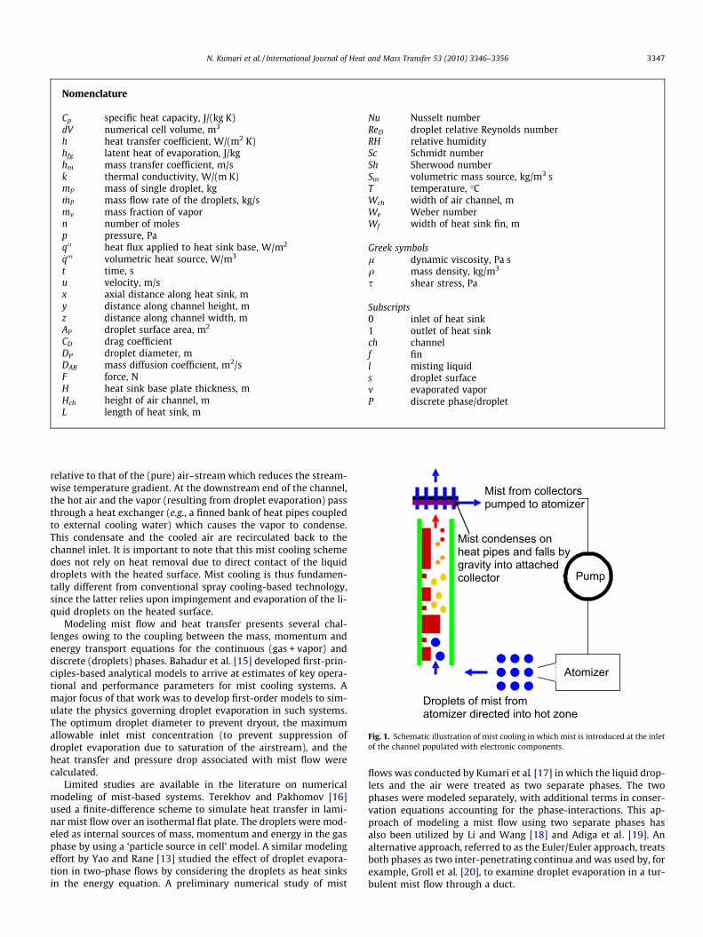
relative to that of the (pure) air–stream which reduces the stream-wise temperature gradient. At the downstream end of the channel,the hot air and the vapor (resulting from droplet evaporation) passthrough a heat exchanger (e.g., a finned bank of heat pipes coupledto external cooling water) which causes the vapor to condense.This condensate and the cooled air are recirculated back to thechannel inlet. It is important to note that this mist cooling schemedoes not rely on heat removal due to direct contact of the liquiddroplets with the heated surface. Mist cooling is thus fundamen-tally different from conventional spray cooling-based technology,since the latter relies upon impingement and evaporation of the li-quid droplets on the heated surface.
Modeling mist flow and heat transfer presents several chal-lenges owing to the coupling between the mass, momentum andenergy transport equations for the continuous (gas + vapor) anddiscrete (droplets) phases. Bahadur et al. [15] developed first-prin-ciples-based analytical models to arrive at estimates of key opera-tional and performance parameters for mist cooling systems. Amajor focus of that work was to develop first-order models to sim-ulate the physics governing droplet evaporation in such systems.The optimum droplet diameter to prevent dryout, the maximumallowable inlet mist concentration (to prevent suppression ofdroplet evaporation due to saturation of the airstream), and theheat transfer and pressure drop associated with mist flow werecalculated.
Limited studies are available in the literature on numericalmodeling of mist-based systems. Terekhov and Pakhomov [16]used a finite-difference scheme to simulate heat transfer in lami-nar mist flow over an isothermal flat plate. The droplets were mod-eled as internal sources of mass, momentum and energy in the gasphase by using a ‘particle source in cell’ model. A similar modelingeffort by Yao and Rane [13] studied the effect of droplet evapora-tion in two-phase flows by considering the droplets as heat sinksin the energy equation. A preliminary numerical study of mist
flows was conducted by Kumari et al. [17] in which the liquid drop-lets and the air were treated as two separate phases. The twophases were modeled separately, with additional terms in conser-vation equations accounting for the phase-interactions. This ap-proach of modeling a mist flow using two separate phases hasalso been utilized by Li and Wang [18] and Adiga et al . [19]. Analternative approach, referred to as the Euler/Euler approach, treatsboth phases as two inter-penetrating continua and was used by, forexample, Groll et al. [20], to examine droplet evaporation in a tur-bulent mist flow through a duct.
Nomenclature
Cp specific heat capacity, J/(kg K)dV numerical cell volume, m3
h heat transfer coefficient, W/(m2 K)hfg latent heat of evaporation, J/kghm mass transfer coefficient, m/sk thermal conductivity, W/(m K)mP mass of single droplet, kg_mP mass flow rate of the droplets, kg/s
mv mass fraction of vaporn number of molesp pressure, Paq0 0 heat flux applied to heat sink base, W/m2
_q000 volumetric heat source, W/m3
t time, su velocity, m/sx axial distance along heat sink, my distance along channel height, mz distance along channel width, mAP droplet surface area, m2
CD drag coefficientDP droplet diameter, mDAB mass diffusion coefficient, m2/sF force, NH heat sink base plate thickness, mHch height of air channel, mL length of heat sink, m
Nu Nusselt numberReD droplet relative Reynolds numberRH relative humiditySc Schmidt numberSh Sherwood numberSm volumetric mass source, kg/m3 sT temperature, �CWch width of air channel, mWe Weber numberWf width of heat sink fin, m
Greek symbolsl dynamic viscosity, Pa sq mass density, kg/m3
s shear stress, Pa
Subscripts0 inlet of heat sink1 outlet of heat sinkch channelf finl misting liquids droplet surfacev evaporated vaporP discrete phase/droplet
Droplets of mist from atomizer directed into hot zone
Pump
Atomizer
Mist condenses on heat pipes and falls bygravity into attached collector
Mist from collectors pumped to atomizer
Fig. 1. Schematic illustration of mist cooling in which mist is introduced at the inletof the channel populated with electronic components.
N. Kumari et al. / International Journal of Heat and Mass Transfer 53 (2010) 3346–3356 3347
The present work further develops and refines the numericalstudy of Kumari et al. [17] to achieve a detailed understanding ofthe flow and thermal performance of mist cooling systems. The‘discrete-phase’ model in the commercially-available CFD softwarepackage FLUENT [21] is used to analyze mist flow through a cop-per-finned heat sink. Parametric analyses are carried out to studythe effect of the inlet droplet diameter and the inlet concentrationof the misting fluid on the heat-dissipation capacity of the heat sink.The thermal characteristics of mist cooling are quantified in terms ofthe thermal resistance and heat transfer coefficients associated withmist flow; the corresponding performance under air flow (no mist) isalso presented for comparison. The results from the modeling effortprovide significant insight into the complex transport phenomenaassociated with mist flows. The heat-dissipation estimates fromthe simulations show that mist cooling offers substantial promisefor enhanced heat-dissipation as compared to conventional aircooling.
Although the present work analyzes mist flow through a heatsink, the modeling approach and framework developed in the pres-ent work can be used for the analysis of a wide range of mist-basedsystems such as telecommunications cabinets and data centercooling systems [17], gas turbine cooling [18], and fire suppressionsystems [19].
2. Droplet evaporation model
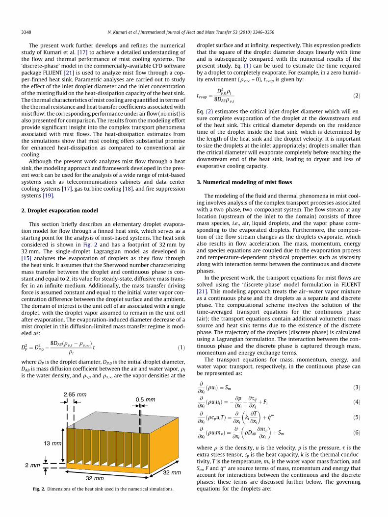
This section briefly describes an elementary droplet evapora-tion model for flow through a finned heat sink, which serves as astarting point for the analysis of mist-based systems. The heat sinkconsidered is shown in Fig. 2 and has a footprint of 32 mm by32 mm. The single-droplet Lagrangian model as developed in[15] analyzes the evaporation of droplets as they flow throughthe heat sink. It assumes that the Sherwood number characterizingmass transfer between the droplet and continuous phase is con-stant and equal to 2, its value for steady-state, diffusive mass trans-fer in an infinite medium. Additionally, the mass transfer drivingforce is assumed constant and equal to the initial water vapor con-centration difference between the droplet surface and the ambient.The domain of interest is the unit cell of air associated with a singledroplet, with the droplet vapor assumed to remain in the unit cellafter evaporation. The evaporation-induced diameter decrease of amist droplet in this diffusion-limited mass transfer regime is mod-eled as:
D2P ¼ D2
P;0 �8DABðqv;s � qv;1Þ
qlt ð1Þ
where DP is the droplet diameter, DP,0 is the initial droplet diameter,DAB is mass diffusion coefficient between the air and water vapor, ql
is the water density, and qv,s and qs,1 are the vapor densities at the
droplet surface and at infinity, respectively. This expression predictsthat the square of the droplet diameter decays linearly with timeand is subsequently compared with the numerical results of thepresent study. Eq. (1) can be used to estimate the time requiredby a droplet to completely evaporate. For example, in a zero humid-ity environment (qv,1 = 0), tevap is given by:
tevap ¼D2
P;0ql
8DABqv ;sð2Þ
Eq. (2) estimates the critical inlet droplet diameter which will en-sure complete evaporation of the droplet at the downstream endof the heat sink. This critical diameter depends on the residencetime of the droplet inside the heat sink, which is determined bythe length of the heat sink and the droplet velocity. It is importantto size the droplets at the inlet appropriately; droplets smaller thanthe critical diameter will evaporate completely before reaching thedownstream end of the heat sink, leading to dryout and loss ofevaporative cooling capacity.
3. Numerical modeling of mist flows
The modeling of the fluid and thermal phenomena in mist cool-ing involves analysis of the complex transport processes associatedwith a two-phase, two-component system. The flow stream at anylocation (upstream of the inlet to the domain) consists of threemass species, i.e., air, liquid droplets, and the vapor phase corre-sponding to the evaporated droplets. Furthermore, the composi-tion of the flow stream changes as the droplets evaporate, whichalso results in flow acceleration. The mass, momentum, energyand species equations are coupled due to the evaporation processand temperature-dependent physical properties such as viscosityalong with interaction terms between the continuous and discretephases.
In the present work, the transport equations for mist flows aresolved using the ‘discrete-phase’ model formulation in FLUENT[21]. This modeling approach treats the air–water vapor mixtureas a continuous phase and the droplets as a separate and discretephase. The computational scheme involves the solution of thetime-averaged transport equations for the continuous phase(air); the transport equations contain additional volumetric masssource and heat sink terms due to the existence of the discretephase. The trajectory of the droplets (discrete phase) is calculatedusing a Lagrangian formulation. The interaction between the con-tinuous phase and the discrete phase is captured through mass,momentum and energy exchange terms.
The transport equations for mass, momentum, energy, andwater vapor transport, respectively, in the continuous phase canbe represented as:
@
@xiðquiÞ ¼ Sm ð3Þ
@
@xiðquiujÞ ¼ �
@p@xiþ @sij
@xjþ Fi ð4Þ
@
@xiðqcpuiTÞ ¼
@
@xiki@T@xi
� �þ _q000 ð5Þ
@
@xiðquimvÞ ¼
@
@xiqDAB
@mv
@xi
� �þ Sm ð6Þ
where q is the density, u is the velocity, p is the pressure, s is theextra stress tensor, cp is the heat capacity, k is the thermal conduc-tivity, T is the temperature, mv is the water vapor mass fraction, andSm, F and _q000 are source terms of mass, momentum and energy thataccount for interactions between the continuous and the discretephases; these terms are discussed further below. The governingequations for the droplets are:Fig. 2. Dimensions of the heat sink used in the numerical simulations.
3348 N. Kumari et al. / International Journal of Heat and Mass Transfer 53 (2010) 3346–3356
dmP
dt¼ �hmðqv;s � qvÞAP ð7Þ
duP
dt¼ 18l
qpD2p
CDReD
24ðu� uPÞ ð8Þ
mPcp;PdTP
dt¼ hAPðT � TPÞ þ hfg
dmP
dtð9Þ
where subscript P represents the droplet, qv is the average vapordensity in the control volume associated with the particle, AP isthe surface area of the droplet, DP is the droplet diameter, CD isthe drag coefficient and T is the local continuous-phase tempera-ture. The momentum of the droplet is affected by the drag force act-ing on the droplet due to the relative motion between the dropletand the air. The energy equation of the droplet assumes no spatialtemperature distribution within the droplet; the droplet energy isaffected by the convective heat transfer and the evaporation pro-cesses. The relative Reynolds number ReD in Eq. (8) is defined as:
ReD ¼qDpjup � uj
lð10Þ
The following correlations [22–24] are used to calculate the masstransfer coefficient hm and the heat transfer coefficient h:
Sh ¼ hmDp
DAB¼ 2:0þ 0:6Re0:5
D Sc1=3 ð11Þ
Nu ¼ hDp
k¼ 2:0þ 0:6Re0:5
D Pr1=3 ð12Þ
The above equations for the Sherwood and Nusselt numbers (devel-oped for steady-state conditions for a droplet surrounded by an infi-nite medium) account for diffusive as well as convective processes,which govern the mass and heat transfer between the droplet andthe continuous phase. In the present work, the transport processis predominantly diffusive, and the second terms on the right handside of Eqs. (11) and (12) have only a small contribution.
The mass, momentum and energy source/sink terms appearingin Eqs. (3)–(6) account for the interactions between the continuousand the discrete phases. These terms are calculated using the fol-lowing equations:
Sm ¼DmP
mP0
_mP0
dVð13Þ
Fi ¼X 18lCDReD
24qpD2p
ðuP;i � uiÞ !
_mPDt ð14Þ
_q000 ¼�mP
mP0cp;PDTP þ
DmP
mP0�hfg þ
Z Tp
Tref
cp;vdT
!" #_mP0
dVð15Þ
where _mP is the mass flow rate of the droplets, DmP is the total evap-orated water vapor mass in the control volume during one time step,�mP is the average droplet mass in the control volume, mP0 is the initialdroplet mass (at the inlet), and dV is the volume of a numerical cell.The energy exchange term includes the sensible heating of the drop-let, the latent heat required for the evaporation process and sensibleheating of the water vapor generated in the evaporation process.
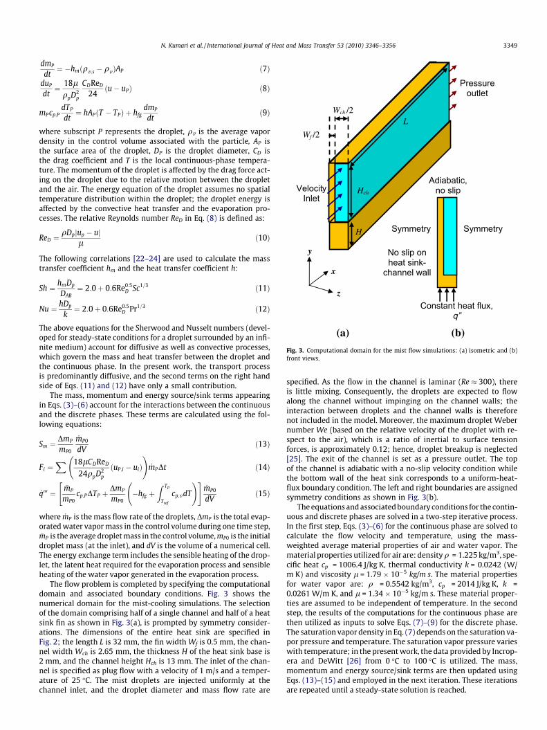
The flow problem is completed by specifying the computationaldomain and associated boundary conditions. Fig. 3 shows thenumerical domain for the mist-cooling simulations. The selectionof the domain comprising half of a single channel and half of a heatsink fin as shown in Fig. 3(a), is prompted by symmetry consider-ations. The dimensions of the entire heat sink are specified inFig. 2; the length L is 32 mm, the fin width Wf is 0.5 mm, the chan-nel width Wch is 2.65 mm, the thickness H of the heat sink base is2 mm, and the channel height Hch is 13 mm. The inlet of the chan-nel is specified as plug flow with a velocity of 1 m/s and a temper-ature of 25 �C. The mist droplets are injected uniformly at thechannel inlet, and the droplet diameter and mass flow rate are
specified. As the flow in the channel is laminar (Re � 300), thereis little mixing. Consequently, the droplets are expected to flowalong the channel without impinging on the channel walls; theinteraction between droplets and the channel walls is thereforenot included in the model. Moreover, the maximum droplet Webernumber We (based on the relative velocity of the droplet with re-spect to the air), which is a ratio of inertial to surface tensionforces, is approximately 0.12; hence, droplet breakup is neglected[25]. The exit of the channel is set as a pressure outlet. The topof the channel is adiabatic with a no-slip velocity condition whilethe bottom wall of the heat sink corresponds to a uniform-heat-flux boundary condition. The left and right boundaries are assignedsymmetry conditions as shown in Fig. 3(b).
The equations and associated boundary conditions for the contin-uous and discrete phases are solved in a two-step iterative process.In the first step, Eqs. (3)–(6) for the continuous phase are solved tocalculate the flow velocity and temperature, using the mass-weighted average material properties of air and water vapor. Thematerial properties utilized for air are: densityq = 1.225 kg/m3, spe-cific heat cp = 1006.4 J/kg K, thermal conductivity k = 0.0242 (W/m K) and viscosity l = 1.79 � 10�5 kg/m s. The material propertiesfor water vapor are: q = 0.5542 kg/m3, cp = 2014 J/kg K, k =0.0261 W/m K, and l = 1.34 � 10�5 kg/m s. These material proper-ties are assumed to be independent of temperature. In the secondstep, the results of the computations for the continuous phase arethen utilized as inputs to solve Eqs. (7)–(9) for the discrete phase.The saturation vapor density in Eq. (7) depends on the saturation va-por pressure and temperature. The saturation vapor pressure varieswith temperature; in the present work, the data provided by Incrop-era and DeWitt [26] from 0 �C to 100 �C is utilized. The mass,momentum and energy source/sink terms are then updated usingEqs. (13)–(15) and employed in the next iteration. These iterationsare repeated until a steady-state solution is reached.
L
H
Wch /2
Hch
Wf /2
Symmetry
Adiabatic, no slip
Constant heat flux, q”
(b)
Symmetry
VelocityInlet
Pressure outlet
No slip on heat sink-
channel wall
(a)
x
y
z
Fig. 3. Computational domain for the mist flow simulations: (a) isometric and (b)front views.
N. Kumari et al. / International Journal of Heat and Mass Transfer 53 (2010) 3346–3356 3349
A uniform heat load of 10 W is applied to the base of the heat sinkas shown in Fig. 3(b), which corresponds to a heat flux q00 of 9766 W/m2. A major objective of the simulations is to quantify the additionalreduction in the heat sink temperature upon replacing airflow with amist flow. The influence of the inlet droplet diameter and the inletmist loading fraction on the thermal performance of the system isquantified through a parametric analysis. Four cases correspondingto different combinations of two inlet droplet sizes and two inletmist loading fractions were simulated as shown in Table 1. Thetwo inlet droplet sizes selected for this parametric analysis were10 lm and 50 lm; these correspond to typical droplet sizes whichcan be obtained from commercially-available mist-generation sys-tems. The two inlet mist loading fractions selected for the parametricanalysis were 1% and 10% of the air mass flow rate. The correspond-ing mass flow rates of (air, water) through the heat sink are(4.22 � 10�4, 4.22 � 10�6) kg/s and (4.22 � 10�4, 4.22 � 10�5) kg/s,respectively. The cooling enhancement upon the use of mist cooling
was quantified by comparison with a baseline case in which the heatsink is air-cooled (inlet air velocity = 1 m/s).
The computational domain used for all the simulations con-sisted of 150,000 cells. A mesh-independence study was conductedwith three resolutions for both air-cooling and mist-cooling cases.For the air-cooled heat sink, the thermal resistance changed byapproximately 3.5% and 2.1% when the number of cells was in-creased from 115,000 to 150,000, and from 150,000 to 260,000,respectively; the corresponding changes in resistance for themist-cooled heat sink were approximately 4.3% and 3.0%. Conse-quently, all the simulation results presented in this work were ob-tained for a domain consisting of 150,000 cells.
4. Results and discussion
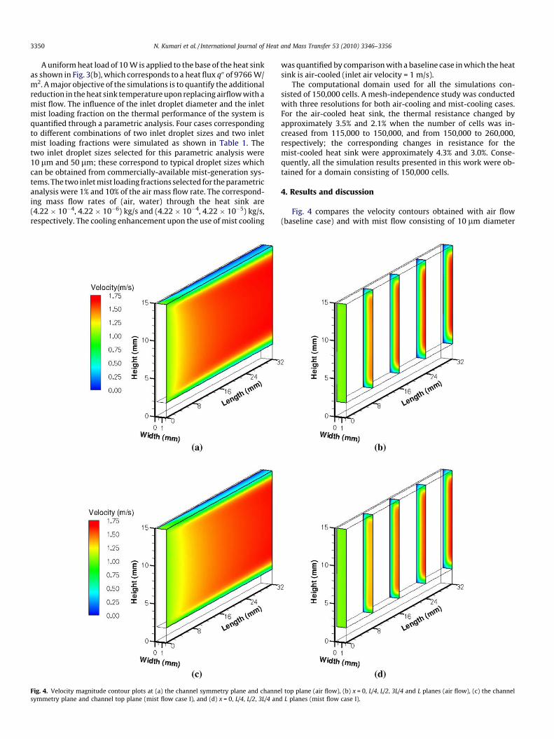
Fig. 4 compares the velocity contours obtained with air flow(baseline case) and with mist flow consisting of 10 lm diameter
Fig. 4. Velocity magnitude contour plots at (a) the channel symmetry plane and channel top plane (air flow), (b) x = 0, L/4, L/2, 3L/4 and L planes (air flow), (c) the channelsymmetry plane and channel top plane (mist flow case I), and (d) x = 0, L/4, L/2, 3L/4 and L planes (mist flow case I).
3350 N. Kumari et al. / International Journal of Heat and Mass Transfer 53 (2010) 3346–3356
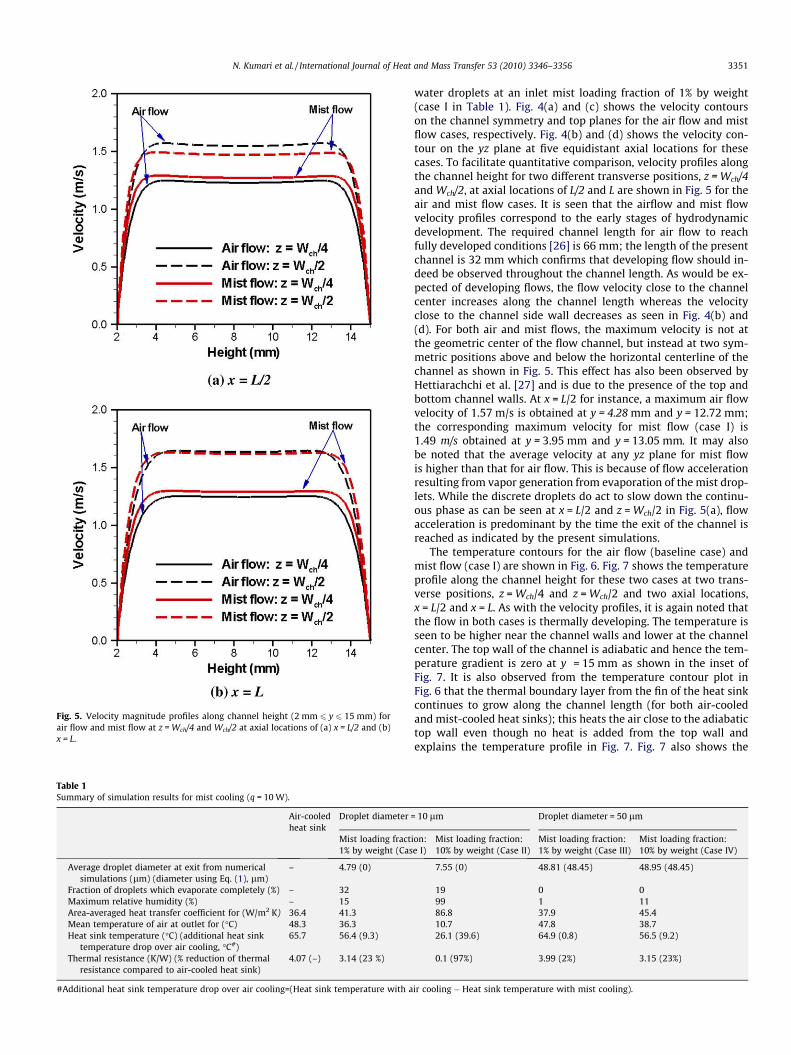
water droplets at an inlet mist loading fraction of 1% by weight(case I in Table 1). Fig. 4(a) and (c) shows the velocity contourson the channel symmetry and top planes for the air flow and mistflow cases, respectively. Fig. 4(b) and (d) shows the velocity con-tour on the yz plane at five equidistant axial locations for thesecases. To facilitate quantitative comparison, velocity profiles alongthe channel height for two different transverse positions, z = Wch/4and Wch/2, at axial locations of L/2 and L are shown in Fig. 5 for theair and mist flow cases. It is seen that the airflow and mist flowvelocity profiles correspond to the early stages of hydrodynamicdevelopment. The required channel length for air flow to reachfully developed conditions [26] is 66 mm; the length of the presentchannel is 32 mm which confirms that developing flow should in-deed be observed throughout the channel length. As would be ex-pected of developing flows, the flow velocity close to the channelcenter increases along the channel length whereas the velocityclose to the channel side wall decreases as seen in Fig. 4(b) and(d). For both air and mist flows, the maximum velocity is not atthe geometric center of the flow channel, but instead at two sym-metric positions above and below the horizontal centerline of thechannel as shown in Fig. 5. This effect has also been observed byHettiarachchi et al. [27] and is due to the presence of the top andbottom channel walls. At x = L/2 for instance, a maximum air flowvelocity of 1.57 m/s is obtained at y = 4.28 mm and y = 12.72 mm;the corresponding maximum velocity for mist flow (case I) is1.49 m/s obtained at y = 3.95 mm and y = 13.05 mm. It may alsobe noted that the average velocity at any yz plane for mist flowis higher than that for air flow. This is because of flow accelerationresulting from vapor generation from evaporation of the mist drop-lets. While the discrete droplets do act to slow down the continu-ous phase as can be seen at x = L/2 and z = Wch/2 in Fig. 5(a), flowacceleration is predominant by the time the exit of the channel isreached as indicated by the present simulations.
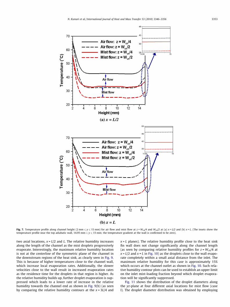
The temperature contours for the air flow (baseline case) andmist flow (case I) are shown in Fig. 6. Fig. 7 shows the temperatureprofile along the channel height for these two cases at two trans-verse positions, z = Wch/4 and z = Wch/2 and two axial locations,x = L/2 and x = L. As with the velocity profiles, it is again noted thatthe flow in both cases is thermally developing. The temperature isseen to be higher near the channel walls and lower at the channelcenter. The top wall of the channel is adiabatic and hence the tem-perature gradient is zero at y = 15 mm as shown in the inset ofFig. 7. It is also observed from the temperature contour plot inFig. 6 that the thermal boundary layer from the fin of the heat sinkcontinues to grow along the channel length (for both air-cooledand mist-cooled heat sinks); this heats the air close to the adiabatictop wall even though no heat is added from the top wall andexplains the temperature profile in Fig. 7. Fig. 7 also shows the
Fig. 5. Velocity magnitude profiles along channel height (2 mm 6 y 6 15 mm) forair flow and mist flow at z = Wch/4 and Wch/2 at axial locations of (a) x = L/2 and (b)x = L.
Table 1Summary of simulation results for mist cooling (q = 10 W).
Air-cooledheat sink
Droplet diameter = 10 lm Droplet diameter = 50 lm
Mist loading fraction:1% by weight (Case I)
Mist loading fraction:10% by weight (Case II)
Mist loading fraction:1% by weight (Case III)
Mist loading fraction:10% by weight (Case IV)
Average droplet diameter at exit from numericalsimulations (lm) (diameter using Eq. (1), lm)
– 4.79 (0) 7.55 (0) 48.81 (48.45) 48.95 (48.45)
Fraction of droplets which evaporate completely (%) – 32 19 0 0Maximum relative humidity (%) – 15 99 1 11Area-averaged heat transfer coefficient for (W/m2 K) 36.4 41.3 86.8 37.9 45.4Mean temperature of air at outlet for (�C) 48.3 36.3 10.7 47.8 38.7Heat sink temperature (�C) (additional heat sink
temperature drop over air cooling, �C#)65.7 56.4 (9.3) 26.1 (39.6) 64.9 (0.8) 56.5 (9.2)
Thermal resistance (K/W) (% reduction of thermalresistance compared to air-cooled heat sink)
4.07 (–) 3.14 (23 %) 0.1 (97%) 3.99 (2%) 3.15 (23%)
#Additional heat sink temperature drop over air cooling=(Heat sink temperature with air cooling � Heat sink temperature with mist cooling).
N. Kumari et al. / International Journal of Heat and Mass Transfer 53 (2010) 3346–3356 3351
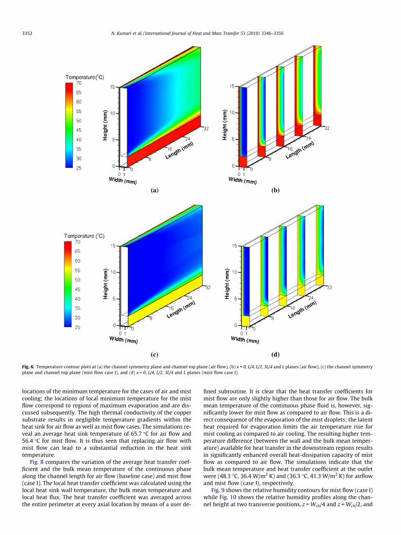
locations of the minimum temperature for the cases of air and mistcooling; the locations of local minimum temperature for the mistflow correspond to regions of maximum evaporation and are dis-cussed subsequently. The high thermal conductivity of the coppersubstrate results in negligible temperature gradients within theheat sink for air flow as well as mist flow cases. The simulations re-veal an average heat sink temperature of 65.7 �C for air flow and56.4 �C for mist flow. It is thus seen that replacing air flow withmist flow can lead to a substantial reduction in the heat sinktemperature.
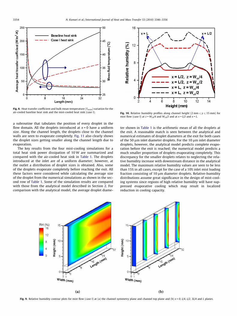
Fig. 8 compares the variation of the average heat transfer coef-ficient and the bulk mean temperature of the continuous phasealong the channel length for air flow (baseline case) and mist flow(case I). The local heat transfer coefficient was calculated using thelocal heat sink wall temperature, the bulk mean temperature andlocal heat flux. The heat transfer coefficient was averaged acrossthe entire perimeter at every axial location by means of a user de-
fined subroutine. It is clear that the heat transfer coefficients formist flow are only slightly higher than those for air flow. The bulkmean temperature of the continuous phase fluid is, however, sig-nificantly lower for mist flow as compared to air flow. This is a di-rect consequence of the evaporation of the mist droplets; the latentheat required for evaporation limits the air temperature rise formist cooling as compared to air cooling. The resulting higher tem-perature difference (between the wall and the bulk mean temper-ature) available for heat transfer in the downstream regions resultsin significantly enhanced overall heat-dissipation capacity of mistflow as compared to air flow. The simulations indicate that thebulk mean temperature and heat transfer coefficient at the outletwere (48.3 �C, 36.4 W/m2 K) and (36.3 �C, 41.3 W/m2 K) for airflowand mist flow (case I), respectively.
Fig. 9 shows the relative humidity contours for mist flow (case I)while Fig. 10 shows the relative humidity profiles along the chan-nel height at two transverse positions, z = Wch/4 and z = Wch/2, and
Fig. 6. Temperature contour plots at (a) the channel symmetry plane and channel top plane (air flow), (b) x = 0, L/4, L/2, 3L/4 and L planes (air flow), (c) the channel symmetryplane and channel top plane (mist flow case I), and (d) x = 0, L/4, L/2, 3L/4 and L planes (mist flow case I).
3352 N. Kumari et al. / International Journal of Heat and Mass Transfer 53 (2010) 3346–3356
two axial locations, x = L/2 and L. The relative humidity increasesalong the length of the channel as the mist droplets progressivelyevaporate. Interestingly, the maximum relative humidity locationis not at the centerline of the symmetric plane of the channel inthe downstream regions of the heat sink, as clearly seen in Fig. 9.This is because of higher temperatures close to the channel wall,which increase local evaporation rates. Additionally, the slowervelocities close to the wall result in increased evaporation ratesas the residence time for the droplets in that region is higher. Asthe relative humidity builds up, further droplet evaporation is sup-pressed which leads to a lower rate of increase in the relativehumidity towards the channel end as shown in Fig. 9(b) (as seenby comparing the relative humidity contours at the x = 3L/4 and
x = L planes). The relative humidity profile close to the heat sinkfin wall does not change significantly along the channel length(as seen by comparing relative humidity profiles for z = Wch/4 atx = L/2 and x = L in Fig. 10) as the droplets close to the wall evapo-rate completely within a small axial distance from the inlet. Themaximum relative humidity for this case is approximately 15%which occurs at the channel outlet as shown in Fig. 10. Such rela-tive humidity contour plots can be used to establish an upper limiton the inlet mist-loading fraction beyond which droplet evapora-tion will be significantly suppressed.
Fig. 11 shows the distribution of the droplet diameters alongthe yz-plane at four different axial locations for mist flow (caseI). The droplet diameter distribution was obtained by employing
Fig. 7. Temperature profile along channel height (2 mm 6 y 6 15 mm) for air flow and mist flow at z = Wch/4 and Wch/2 at (a) x = L/2 and (b) x = L. (The insets show thetemperature profile near the top adiabatic wall, 14.95 mm 6 y 6 15 mm; the temperature gradient at the wall is confirmed to be zero).
N. Kumari et al. / International Journal of Heat and Mass Transfer 53 (2010) 3346–3356 3353
a subroutine that tabulates the position of every droplet in theflow domain. All the droplets introduced at x = 0 have a uniformsize. Along the channel length, the droplets close to the channelwalls are seen to evaporate completely. Fig. 11 also clearly showsthe droplet sizes getting smaller along the channel length due toevaporation.
The key results from the four mist-cooling simulations for atotal heat sink power dissipation of 10 W are summarized andcompared with the air-cooled heat sink in Table 1. The dropletsintroduced at the inlet are of a uniform diameter; however, atthe outlet a distribution of droplet sizes is obtained. Also, someof the droplets evaporate completely before reaching the exit. Allthese factors were considered while calculating the average sizeof the droplet from the numerical simulations as shown in the sec-ond row of Table 1. Some of the simulation results are comparedwith those from the analytical model described in Section 2. Forcomparison with the analytical model, the average droplet diame-
ter shown in Table 1 is the arithmetic mean of all the droplets atthe exit. A reasonable match is seen between the analytical andnumerical estimates of droplet diameters at the exit for both casesof the 50 lm inlet diameter droplets. For the 10 lm inlet diameterdroplets, however, the analytical model predicts complete evapo-ration before the exit is reached; the numerical model predicts amuch smaller proportion of droplets evaporating completely. Thisdiscrepancy for the smaller droplets relates to neglecting the rela-tive humidity increase with downstream distance in the analyticalmodel. The maximum relative humidity values are seen to be lessthan 15% in all cases, except for the case of a 10% inlet mist loadingfraction consisting of 10 lm diameter droplets. Relative-humiditydistributions assume great significance in the design of mist-cool-ing systems since regions of high relative humidity will have sup-pressed evaporative cooling which may result in localizedreduction in cooling capacity.
Fig. 9. Relative humidity contour plots for mist flow (case I) at (a) the channel symmetry plane and channel top plane and (b) x = 0, L/4, L/2, 3L/4 and L planes.
Fig. 8. Heat transfer coefficient and bulk mean temperature (Tmean) variation for theair-cooled baseline heat sink and the mist-cooled heat sink (case I). Fig. 10. Relative humidity profiles along channel height (2 mm 6 y 6 15 mm) for
mist flow (case I) at z = Wch/4 and Wch/2 and at x = L/2 and x = L.
3354 N. Kumari et al. / International Journal of Heat and Mass Transfer 53 (2010) 3346–3356
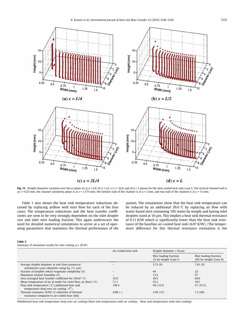
Table 1 also shows the heat sink temperature reductions ob-tained by replacing airflow with mist flow for each of the fourcases. The temperature reductions and the heat transfer coeffi-cients are seen to be very strongly dependent on the inlet dropletsize and inlet mist loading fraction. This again underscores theneed for detailed numerical simulations to arrive at a set of oper-ating parameters that maximize the thermal performance of the
system. The simulations show that the heat sink temperature canbe reduced by an additional 39.6 �C by replacing air flow withwater-based mist containing 10% water by weight and having inletdroplets sized at 10 lm. This implies a heat sink thermal resistanceof 0.11 K/W which is significantly lower than the heat sink resis-tance of the baseline air-cooled heat sink (4.07 K/W). (The temper-ature difference for this thermal resistance estimation is the
Fig. 11. Droplet diameter variation over the yz plane at (a) x = L/4, (b) x = L/2, (c) x = 3L/4, and (d) x = L planes for the mist-cooled heat sink (case I). The vertical channel wall isat z = 0.25 mm, the channel symmetry plane is at z = 1.575 mm; the bottom wall of the channel is at y = 2 mm, and top wall of the channel is at y = 15 mm.
Table 2Summary of simulation results for mist cooling (q = 20 W).
Air-cooled heat sink Droplet diameter = 10 lm
Mist loading fraction:1% by weight (Case I)
Mist loading fraction:10% by weight (Case II)
Average droplet diameter at exit from numericalsimulations (lm) (diameter using Eq. (1), lm)
– 3.73 (0) 7.01 (0)
Fraction of droplets which evaporate completely (%) – 44 22Maximum relative humidity (%) – 13.2 97Area averaged heat transfer coefficient for (W/m2 �C) 35.9 39.5 64.0Mean temperature of air at outlet for (mist flow, air flow) (�C) 71.1 55.2 18.7Heat sink temperature (�C) (additional heat sink
temperature drop over air cooling, �C#)106.5 94 (12.5) 51 (55.5)
Thermal resistance (K/W) (% reduction of thermalresistance compared to air-cooled heat sink)
4.08 (–) 3.45 (15) 1.3 (68)
#Additional heat sink temperature drop over air cooling=(Heat sink temperature with air cooling � Heat sink temperature with mist cooling).
N. Kumari et al. / International Journal of Heat and Mass Transfer 53 (2010) 3346–3356 3355
difference between the heat sink temperature and the inlet airtemperature). It is important to note that the mean temperatureof air at the outlet is lower than the inlet air temperature for caseII; this results because of substantial evaporation-induced coolingof the air stream. Table 1 shows that smaller-diameter droplets re-sult in higher reductions in the thermal resistance of the heat sinkcompared to the larger-diameter droplets (for the same mistloading fraction). This is due to the larger surface area-to-volumeratio of the smaller droplets and the higher evaporation rate thatresults. Higher mist loading fractions lead to smaller thermal resis-tance reductions; however, there will be an upper limit on theloading fraction, above which relative humidity will suppressevaporation.
All the results presented thus far were for a heat sink dissipa-tion of q = 10 W. In order to quantify the potential of mist coolingat higher heat fluxes, another set of simulations was carried outfor a heat-dissipation of 20 W (q00 = 19,532 W/m2), the results ofwhich are summarized in Table 2. The inlet velocity of the mistis maintained at 1 m/s and the inlet droplet diameter was selectedas 10 lm in the two simulations. Two simulations were carried outcorresponding to inlet mist loading fractions of 1% and 10%, respec-tively, and compared to an air-cooled heat sink with q = 20 W. Theresults indicate that mist cooling can significantly reduce the heatsink temperatures and thermal resistances as compared to air cool-ing at higher heat fluxes as well. As an illustration Table 2 showsthat the heat sink temperature can be reduced by an additional55.5 �C by replacing air flow with a water-based mist (10% waterby weight, inlet droplet diameter = 10 lm). The higher heat fluxis sustained by higher droplet evaporation rates which is reflectedin a higher percentage of droplets that evaporate completely in thechannel (as compared to similar simulations for q=10 W). These re-sults confirm that mist cooling offers excellent potential for thedevelopment of enhanced heat transfer solutions.
5. Conclusions
The capabilities of mist flow and heat transfer in heat sinks isinvestigated through detailed numerical modeling. Two sets ofcoupled transport equations are solved: the first set of equationscorresponds to the continuous phase (air), while the second setof equations corresponds to the discrete phase (individual drop-lets). The simulations reveal the complex nature of the fluidmechanics and heat transfer associated with mist flows. It is seenthat the inlet droplet diameter and the loading fraction of the mist-ing fluid are key parameters which influence droplet evaporationand the thermal performance of mist flows. The reduction inheat-sink temperature upon replacing the air flow with mist flowis directly quantified; additionally, the thermal resistances andheat transfer coefficients for mist flows are also evaluated andcompared to air flows. The present work underscores the impor-tance of detailed numerical analyses for the performance predic-tion and optimization of mist-based systems. The heat transferresults from the present work highlight the promise of mist coolingfor high-heat-flux thermal management; the present simulationsindicate that the heat sink thermal resistance can be reduced byup to 97% upon replacing air flow with an evaporating mist flow.
References
[1] R.C. Chu, R.E. Simons, M.J. Ellsworth, R.R. Schmidt, V. Cozzolino, Review ofcooling technologies for computer products, IEEE Trans. Dev. Mater. Reliab. 4(4) (2004) 568–585.
[2] T.A. Shedd, A.G. Pautsch, Spray impingement cooling with single and multiplenozzle arrays. Part 2: visualization and empirical models, Int. J. Heat MassTransfer 48 (2005) 3176–3184.
[3] L. Lin, R. Ponnappan, Heat transfer characteristics of spray cooling in a closedloop, Int. J. Heat Mass Transfer 46 (2003) 3737–3746.
[4] S. Freund, A.G. Pautsch, T.A. Shedd, S. Kabelac, Local heat transfer coefficientsin spray cooling systems measured with temperature oscillation IRthermography, Int. J. Heat Mass Transfer 50 (2007) 1953–1962.
[5] A.G. Pautsch, T.A. Shedd, Adiabatic and diabatic measurements of the liquidfilm thickness during spray cooling with FC 72, Int. J. Heat Mass Transfer 49(2006) 2610–2618.
[6] C.M. Kendall, J.P. Holman, Spray cooling heat transfer with subcooledtrichlorotrifluoroethane (Freon-113) for vertical constant heat flux surfaces,in: Proceedings of IMECE, Atlanta, 1996.
[7] D.E. Tilton, C.E. Tilton, M.R. Pais, M.J. Morgan, High-flux spray cooling in asimulated multichip module, in: ASME National Heat Transfer Conference, SanDiego, CA, 1992.
[8] T. Wang, J.L. Gaddis, X. Li, Mist/steam heat transfer of multiple rows ofimpinging jets, Int. J. Heat Mass Transfer 48 (2005) 5179–5191.
[9] H. Barrow, C.W. Pope, Droplet evaporation with respect to the effectiveness ofwater-mist cooling, Appl. Energy 84 (2007) 404–412.
[10] X. Li, J.L. Gaddis, T. Wang, Mist/steam cooling by a row of impinging jets, Int. J.Heat Mass Transfer 46 (2003) 2279–2290.
[11] S.L. Lee, Z.H. Yang, Y. Hsyua, Cooling of a heated surface by mist flow, ASME J.Heat Transfer 116 (1994) 167–172.
[12] K.M. Graham, S. Ramadhyani, Experimental and theoretical studies of mist jetimpingement cooling, ASME J. Heat Transfer 118 (1996) 343–349.
[13] S. Yao, A. Rane, Heat transfer of laminar mist flow in tubes, ASME J. HeatTransfer 102 (1980) 678–683.
[14] M. Trela, An approximate calculation of heat transfer during flow of an air–water mist along a heated flat plate, Int. J. Heat Mass Transfer 24 (1981) 749–755.
[15] V. Bahadur, M. Hodes, A. Lyons, S. Krishnan, S.V. Garimella, Enhanced coolingin a sealed cabinet using an evaporating-condensing dielectric mist, in:Proceedings of ITHERM, Orlando, FL, 2008, pp. 1191–1198.
[16] V.I. Terekhov, M.A. Pakhomov, Numerical study of heat transfer in a laminarmist flow over an isothermal flat plate, Int. J. Heat Mass Transfer 45 (2002)2077–2085.
[17] N. Kumari, V. Bahadur, M. Hodes, T. Salamon, A. Lyons, P. Kolodner, S.V.Garimella, Numerical analysis of mist-cooled high-performance componentsin cabinets, in: Proceedings of ASME 2009 InterPACK Conference, IPACK2009-89269, San Francisco, CA, 2009.
[18] X. Li, T. Wang, Two-phase flow simulation of mist film cooling on turbineblades with conjugate internal cooling, ASME J. Heat Transfer 130 (2008)102901.1–102901.8.
[19] K.C. Adiga, R.F. Hatcher, R.S. Sheinson, F.W. Williams, S. Ayers, A computationaland experimental study of ultra fine water mist as a total flooding agent, FireSafety J. 42 (2007) 150–160.
[20] R. Groll, S. Jakirlic, C. Tropea, Comparative study of Euler/Euler and Euler/Lagrange approaches simulating evaporation in a turbulent gas–liquid flow,Int. J. Numer. Methods Fluids 59 (2009) 873–906.
[21] FLUENT 6 User’s Guide, Lebanon, NH, Fluent Inc., 2000.[22] W.E. Ranz, W.R. Marshall, Evaporation from drops, Part I and II, Chem. Eng.
Progr. 48 (1952) 141–146. and 173–180.[23] M. Strub, O. Jabbour, F. Strub, J.P. Bédécarrats, Experimental study and
modeling of the crystallization of a water droplet, Int. J. Refrig. 26 (2003) 59–68.
[24] V. Novak, D.L. Sadowski, K.G. Schoonover, S. Shin, S.I. Abdel-Khalik, S.M.Ghiaasian, Heat transfer in two-component internal mist cooling Part II:mechanistic modeling, Nucl. Eng. Des. 238 (2008) 2351–2358.
[25] N. Kumari, J. Abraham, Interaction of decelerating drops moving in tandem,Atom. Sprays 18 (3) (2003) 191–241.
[26] F.P. Incropera, D.P. Dewitt, Fundamentals of Heat and Mass Transfer, fifth ed.,Wiley, New York, 2001.
[27] H.D.M. Hettiarachchi, M. Colubvic, W.M. Worek, W.J. Minkowycz, Three-dimensional laminar slip-flow and heat transfer in a rectangular microchannelwith constant wall temperature, Int. J. Heat Mass Transfer 51 (2008) 5088–5096.
3356 N. Kumari et al. / International Journal of Heat and Mass Transfer 53 (2010) 3346–3356
Related Documents