431 ANALYSIS OF DESICCANT COOLING SYSTEM Gaurav Pundir 1 * and S N Mishra 1 *Corresponding Author: Gaurav Pundir, [email protected] Desiccant cooling systems are heat-driven cooling units and they can be used as an alternative to the conventional vapor compression and absorption cooling systems. Its operation is based on the use of a rotary dehumidifier Desiccant Wheel (DW) in which air is dehumidified. The resulting dry air is somewhat cooled in a sensible heat exchanger Rotary Regenerator (RR), and then further cooled by an evaporative cooler. The resulting cool air is directed into the room. The system may be operated in a closed cycle or more commonly in an open cycle in ventilation or recirculation modes. A heat supply is needed in the system to regenerate the desiccant (natural Zeolite) and a low-grade heat at a temperature of about 60.95. C may be used. The thermal and reversible COPs of an open desiccant cooling system depend on operating conditions of the system. In this paper, we propose a desiccant cooling system with certain operating characteristics for all components. We use this operation as a standard model for calculating thermal and reversible COPs for both ventilation and recirculation modes of the system operation. Parametric studies are performed to investigate the effects of ambient temperature and relative humidity on the various COP terms and cooling load. Keywords: Desiccants, Desiccant cycle, First and second law analysis of desiccant cooling system INTRODUCTION Desiccants has high affinity towards moisture they can draw water vapour directly from the surrounding air This affinity can be regenerated continually by applying heat to the desiccant material to drive off the collected moisture. Several materials are desiccants; that is they attract and hold water vapor. natural fibers, clays ,wood and many synthetics materials attract and release moisture like commercial ISSN 2278 – 0149 www.ijmerr.com Vol. 1, No. 3, October 2012 © 2012 IJMERR. All Rights Reserved Int. J. Mech. Eng. & Rob. Res. 2012 1 Mechanical Engineering, Department Kamla Nehru Institute of Technology, Sultanpur, Uttar Pradesh, India. desiccants do, but they lack of holding capacity of some special desiccant materials. For example, woolen carpet fibers attract up to 21% of their dry weight in water vapor, and nylon can take up almost 6% of its weight in water. In contrast, a commercial desiccant takes up between 10 and 110% of its dry weight in water vapor, depending on its type. and the moisture available in the environment. Furthermore, commercial desiccants carry on Research Paper

Welcome message from author
This document is posted to help you gain knowledge. Please leave a comment to let me know what you think about it! Share it to your friends and learn new things together.
Transcript
431
Int. J. Mech. Eng. & Rob. Res. 2012 Gaurav Pundir and S N Mishra, 2012
ANALYSIS OF DESICCANT COOLING SYSTEM
Gaurav Pundir1* and S N Mishra1
*Corresponding Author: Gaurav Pundir,[email protected]
Desiccant cooling systems are heat-driven cooling units and they can be used as an alternativeto the conventional vapor compression and absorption cooling systems. Its operation is basedon the use of a rotary dehumidifier Desiccant Wheel (DW) in which air is dehumidified. Theresulting dry air is somewhat cooled in a sensible heat exchanger Rotary Regenerator (RR),and then further cooled by an evaporative cooler. The resulting cool air is directed into the room.The system may be operated in a closed cycle or more commonly in an open cycle in ventilationor recirculation modes. A heat supply is needed in the system to regenerate the desiccant(natural Zeolite) and a low-grade heat at a temperature of about 60.95. C may be used. Thethermal and reversible COPs of an open desiccant cooling system depend on operating conditionsof the system. In this paper, we propose a desiccant cooling system with certain operatingcharacteristics for all components. We use this operation as a standard model for calculatingthermal and reversible COPs for both ventilation and recirculation modes of the system operation.Parametric studies are performed to investigate the effects of ambient temperature and relativehumidity on the various COP terms and cooling load.
Keywords: Desiccants, Desiccant cycle, First and second law analysis of desiccant coolingsystem
INTRODUCTIONDesiccants has high affinity towards moisturethey can draw water vapour directly from thesurrounding air This affinity can be regeneratedcontinually by applying heat to the desiccantmaterial to drive off the collected moisture.Several materials are desiccants; that is theyattract and hold water vapor. natural fibers,clays ,wood and many synthetics materialsattract and release moisture like commercial
ISSN 2278 – 0149 www.ijmerr.comVol. 1, No. 3, October 2012
© 2012 IJMERR. All Rights Reserved
Int. J. Mech. Eng. & Rob. Res. 2012
1 Mechanical Engineering, Department Kamla Nehru Institute of Technology, Sultanpur, Uttar Pradesh, India.
desiccants do, but they lack of holdingcapacity of some special desiccant materials.For example, woolen carpet fibers attract upto 21% of their dry weight in water vapor, andnylon can take up almost 6% of its weight inwater. In contrast, a commercial desiccanttakes up between 10 and 110% of its dry weightin water vapor, depending on its type. and themoisture available in the environment.Furthermore, commercial desiccants carry on
Research Paper
432
Int. J. Mech. Eng. & Rob. Res. 2012 Gaurav Pundir and S N Mishra, 2012
to attract moisture even when the surroundingair is quite dry.
All desiccants perform in a similar way thatthey attract moisture from the surrounding untilthey reach equilibrium with the surrounding air.Moisture is usually detached from thedesiccant by heating it to temperaturesbetween 120 and 500 F and exposing it to ascavenger airstream. After the desiccant dries,it must be cooled so that it can attract moistureonce again. It always generates sensible heatequal to the latent heat of water vapor takenup by the desiccant, plus an additional heat ofsorption that varies between 5 and 25% of thelatent heat of the water vapor. This heat istransferred to the desiccant and thesurrounding air.
The process of attracting and holdingmoisture is described as either adsorption orabsorption, depending on whether thedesiccant undergoes a chemical change as ittakes on moisture. Adsorption does not changethe desiccant except by the addition of theweight of water vapor, similar in some ways toa sponge soaking up water. Absorption, on theother hand, changes the desiccant. Anexample of this is table salt, which changesfrom a solid to a liquid as it absorbs moisture.
Sorbents are materials that have an abilityto attract and hold gases or liquids. They canbe used to attract gases or liquids other thanwater vapor, a characteristic that makes themvery useful in chemical separation processes.Desiccants are subset of sorbents; they havea particular affinity for water.
TYPES OF DESICCANTSDesiccants can be solids or liquids, Liquidabsorption dehumidification can best be
explained by comparing it to the operation ofan air washer. When air passes through an airwasher, its dewpoint approaches that of thetemperature of the water supplied to theequipment. Less humid air is humidified andmore humid air is dehumidified. In a similarmanner, a liquid absorption dehumidifiercontacts air with a liquid desiccant solution.The liquid has a vapor pressure lower thanwater at the same temperature, and when theair passing over this solution reduced vaporpressure, and then it is dehumidified. The vaporpressure of a liquid absorption solution isdirectly proportional to its temperature andinversely proportional to concentration(Kanoglu and Yildirm, 2003).
In application, the behavior of a liquiddesiccant can be controlled by adjusting itsconcentration, its temperature, or both. simpleheaters and coolers controlled the Desiccanttemperature. Concentration is controlled byheating the desiccant to drive moisture out intoa waste airstream or directly to theambient.The absorption process is limited bythe surface area of a desiccant exposed tothe air being dehumidified and the contact timeallowed for the reaction. More surface area andmore contact time allows the desiccant toapproach its theoretical capacity.
Adsorbents are solid materials with a terrificinternal surface area per unit of mass; a singlegram can have more than 50,000 ft2 of surfacearea. Structurally, they resemble a rigidsponge, and the surface of the sponge in turnresembles the ocean coastline of a fjord. Thisanalogy indicates the scale of the differentsurfaces in an adsorbent. The fjords can becompared to the capillaries in the adsorbent.The spaces between the grains of sand on the

433
Int. J. Mech. Eng. & Rob. Res. 2012 Gaurav Pundir and S N Mishra, 2012
fjord beaches can be compared to the spacesbetween the individual molecules of theadsorbent, all of which have the capacity tohold water molecules. The bulk of the adsorbedwater is contained by condensation into thecapillaries, and the majority of the surface areathat attracts individual water molecules is inthe crystalline structure of the material itself.Adsorbents attract moisture because of theelectrical field at the desiccant surface. Thefield is not uniform in either force or charge,so it attracts polarized water molecules thathave an opposite charge from specific siteson the desiccant surface. When the completesurface is covered, the adsorbent can hold stillmore moisture, as vapor condenses into thefirst water layer and fills the capillariesthroughout the material (Dauo et al., 2004).
All desiccants function by the samemechanism-transferring moisture because ofa difference between the water vapor pressureat their surface and that of the surrounding air.When the vapor pressure at the desiccantsurface is lower than that of the air, thedesiccant attracts moisture. When the surfacevapor pressure is higher than that of thesurrounding air, the desiccant releasesmoisture.
Figure 1 shows the relationship between themoisture content of the desiccant and itssurface vapor pressure. As the moisturecontent of the desiccant rises, so does thewater vapor pressure at its surface. At somepoint, the vapor pressure at the desiccant isthe same as that of the air and the two are inequilibrium (Ashrae, 1997). Then moisturecannot move in either direction until someexternal force changes the vapor pressure atthe desiccant or in the air.
Figure 1 also shows the impact oftemperature on the vapor pressure at thedesiccant. Both higher temperatures andincreased moisture content increase the vaporpressure at the surface. When the surfacevapor pressure exceeds that of thesurrounding air, moisture leaves (Hirunlabhaet al., 2005) the desiccants process calledreactivation or regeneration.After thedesiccant is dried (reactivated) by the heat,its vapor pressure remains high, so that it hasvery little ability to absorb moisture. Coolingthe desiccant reduces its surface vaporpressure so it can absorb moisture once again.The complete cycle is illustrated in Ma et al.(2004) Figure 1.
MATHEMATICAL MODELLINGVentilation Mode
First Law Analysis
In ventilation mode air is first enter in thedesiccant wheel where it can dehumidify and
Figure 1: Desiccant Cycle
434
Int. J. Mech. Eng. & Rob. Res. 2012 Gaurav Pundir and S N Mishra, 2012
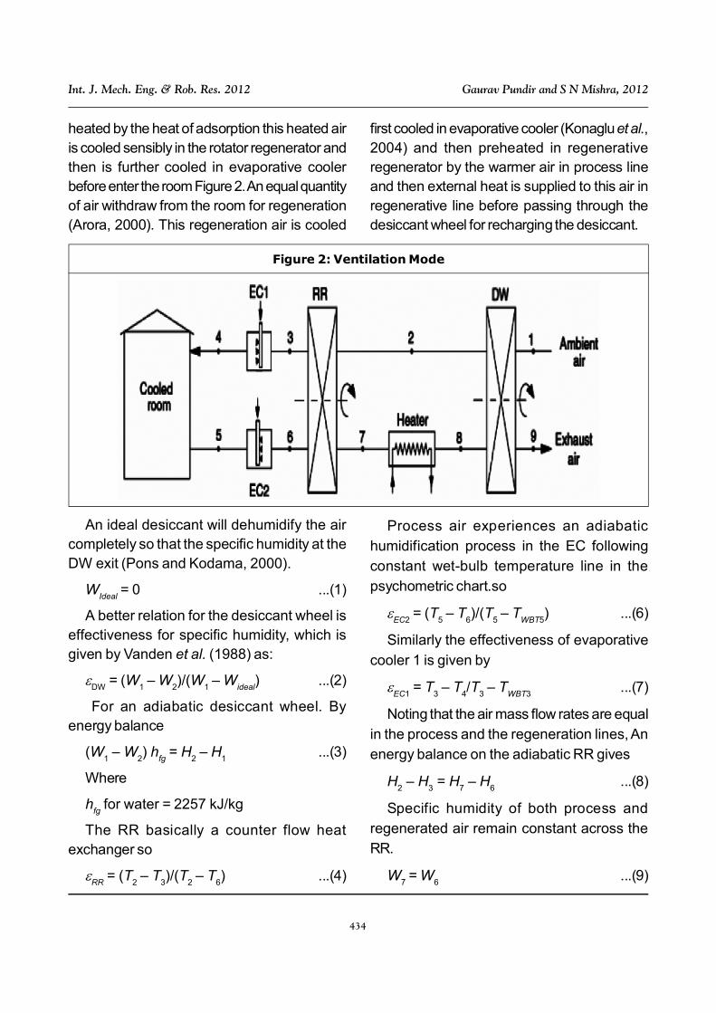
heated by the heat of adsorption this heated airis cooled sensibly in the rotator regenerator andthen is further cooled in evaporative coolerbefore enter the room Figure 2. An equal quantityof air withdraw from the room for regeneration(Arora, 2000). This regeneration air is cooled
first cooled in evaporative cooler (Konaglu et al.,2004) and then preheated in regenerativeregenerator by the warmer air in process lineand then external heat is supplied to this air inregenerative line before passing through thedesiccant wheel for recharging the desiccant.
Figure 2: Ventilation Mode
An ideal desiccant will dehumidify the aircompletely so that the specific humidity at theDW exit (Pons and Kodama, 2000).
WIdeal
= 0 ...(1)
A better relation for the desiccant wheel iseffectiveness for specific humidity, which isgiven by Vanden et al. (1988) as:
DW
= (W1 – W
2)/(W
1 – W
ideal) ...(2)
For an adiabatic desiccant wheel. Byenergy balance
(W1 – W
2) h
fg = H
2 – H
1...(3)
Where
hfg
for water = 2257 kJ/kg
The RR basically a counter flow heatexchanger so
RR
= (T2 – T
3)/(T
2 – T
6) ...(4)
Process air experiences an adiabatichumidification process in the EC followingconstant wet-bulb temperature line in thepsychometric chart.so
EC2
= (T5 – T
6)/(T
5 – T
WBT5) ...(6)
Similarly the effectiveness of evaporative
cooler 1 is given by
EC1
= T3 – T
4/T
3 – T
WBT3...(7)
Noting that the air mass flow rates are equalin the process and the regeneration lines, Anenergy balance on the adiabatic RR gives
H2 – H
3 = H
7 – H
6...(8)
Specific humidity of both process andregenerated air remain constant across theRR.
W7 = W
6...(9)
435
Int. J. Mech. Eng. & Rob. Res. 2012 Gaurav Pundir and S N Mishra, 2012
By Konaglu et al. (2004) anothereffectiveness of the desiccant wheel is
DW1
= (T2 – T
1)/(T
8 – T
1) ...(10)
For sensible heating process
W8 = W
7...(11)
State 5 is the room state. The external heatsupplied to the regeneration air is given by
qin = H
8 – H
7...(12)
The cooling capacity of the system is givenby
qcool
= H5 – H
4...(13)
qregen
= H8 – H
7...(14)
COP = (qcool
/qregen
) = (H5 – H
4)/(H
8 – H
7)
...(15)
SECOND LAW ANALYSISThe cooling system would be reversible if theheat from the heat source were transferred toa Carnot heat engine, and the work output ofthis engine is supplied to a Carnot refrigeratorto remove heat from the cooled space.
COPC = q
cool/q
in =
th,cCOP
RC (Vlku and
Mobedi)
= (1 – Tamb
/Tsource
) (Tspace
/Tamb
– Tspace
)...(16)
Lavan et al. (1982) and Pons and Kodama(2000) investigated the consequences of theopen nature of the cycle with differentapproaches (Table 1). We follow the approachpresented by Lavan et al. (1982), which isbased on using equivalent Carnottemperatures for the evaporator, condenser,and heat source. The reversible COP of theopen desiccant cooling systems wasexpressed using the equivalent Carnottemperatures approach as:
COPrev
= (1 – Tc/T
s) (T
e/T
c– T
e) ...(17)
where Ts, T
e and T
c are the equivalent
temperatures for the heat source, evaporator,and condenser, respectively. The first one isdefined as the ratio of the actual COP to thereversible COP under the same operatingconditions:
sys
= COP/COPrev
...(18)
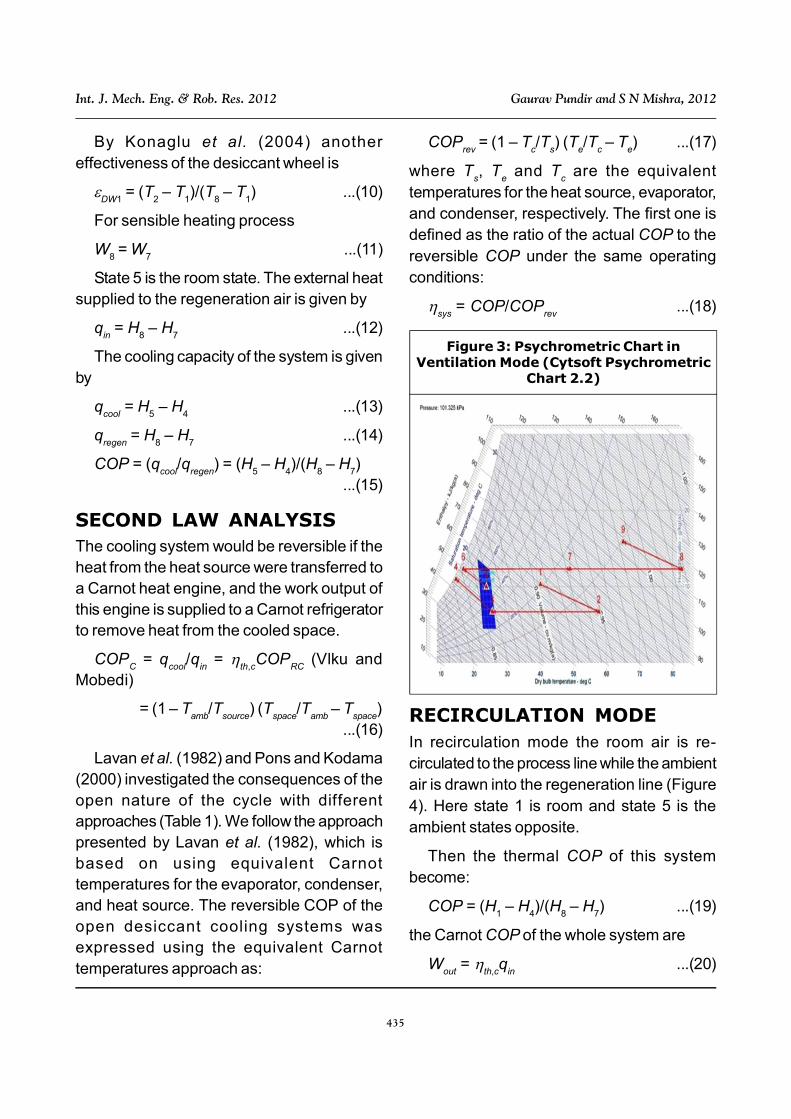
Figure 3: Psychrometric Chart inVentilation Mode (Cytsoft Psychrometric
Chart 2.2)
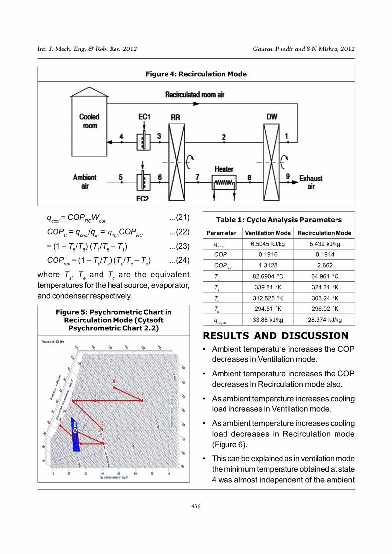
RECIRCULATION MODEIn recirculation mode the room air is re-circulated to the process line while the ambientair is drawn into the regeneration line (Figure4). Here state 1 is room and state 5 is theambient states opposite.
Then the thermal COP of this systembecome:
COP = (H1 – H
4)/(H
8 – H
7) ...(19)
the Carnot COP of the whole system are
Wout
= th,c
qin
...(20)
436
Int. J. Mech. Eng. & Rob. Res. 2012 Gaurav Pundir and S N Mishra, 2012
qcool
= COPRC
Wout
...(21)
COPC = q
cool/q
in =
th,cCOP
RC...(22)
= (1 – T5/T
8) (T
1/T
5 – T
1) ...(23)
COPrev
= (1 – Tc/T
s) (T
e/T
c – T
e) ...(24)
where Ts, T
e and T
c are the equivalent
temperatures for the heat source, evaporator,and condenser respectively.
RESULTS AND DISCUSSION• Ambient temperature increases the COP
decreases in Ventilation mode.
• Ambient temperature increases the COPdecreases in Recirculation mode also.
• As ambient temperature increases coolingload increases in Ventilation mode.
• As ambient temperature increases coolingload decreases in Recirculation mode(Figure 6).
• This can be explained as in ventilation modethe minimum temperature obtained at state4 was almost independent of the ambient
Figure 4: Recirculation Mode
Figure 5: Psychrometric Chart inRecirculation Mode (CytsoftPsychrometric Chart 2.2)
Table 1: Cycle Analysis Parameters
Parameter Ventilation Mode Recirculation Mode
qcool
6.5045 kJ/kg 5.432 kJ/kg
COP 0.1916 0.1914
COPrev
1.3128 2.662
T8
82.6904 °C 64.961 °C
Ts
339.81 °K 324.31 °K
Tc
312.525 °K 303.24 °K
Te
294.51 °K 296.02 °K
qregen
33.88 kJ/kg 28.374 kJ/kg

437
Int. J. Mech. Eng. & Rob. Res. 2012 Gaurav Pundir and S N Mishra, 2012
temperature since the ideal DW cancompletely dehumidify the inlet ambient airand an increased ambient temperature withthe same relative humidity means a higherspecific humidity at the inlet and thisrequires a higher regeneration heat to besupplied. In recirculation mode, the
regeneration heat supplied remainsconstant since it is set equal the latent heatremoved from the recalculated roomprocess air whose state does not change.The cooling load decreases since a higherambient temperature corresponds to ahigher temp. at state 4.
Figure 6: Graphs at Different Condition
(a) Ambient Temp. vs. COP (b) Ambient Temp. vs. Cooling Load
(c) Ambient Temp. vs. COP (d) Ambient Temp. vs. Cooling Load

438
Int. J. Mech. Eng. & Rob. Res. 2012 Gaurav Pundir and S N Mishra, 2012
REFRENCES1. Arora C P (2000), Refrigeration and Air-
Conditioning.
2. Ashrae (1997), ASHRAE Handbook ofFundamentals, American Society ofHeating, Refrigerating, and Air-Conditioning Engineers, New York.
3. Cengel Y A and Boles M A (2002),Thermodynamics: An EngineeringApproach, 4th Edition, McGraw-Hill, NewYork.
4. Cytsoft Psychrometric Calculator 1.0.
5. Cytsoft Psychrometric Chart 2.2.
6. Dauo K, Wang R Z and Xia Z Z (2004),“Desiccant Cooling Air Conditioning: AReview”, Renewable and SustainableEnergy, Vol. 10, pp. 55-77.
7. Hirunlabha J, Charoenwata R, KhedaribJ and Sombat Teekasap (2005),“Feasibility Study of Desiccant Air-Conditioning System in Thailand”,Building & Environmental, Vol. 42, p. 572.
8. Jain S and Dhar P L (1995), “Evaluationof Solid Desiccant Based EvaporativeCooling Cycles for Typical Hot andHumid Climates”, Int. J. Refri., Vol. 18,pp. 287-296.
9. Kanoglu M, Bolatturk A and Altuntop N(2006), “Effect of Ambient Conditions onthe First and Second Law Performance
of Open Desiccant Cooling Process”,Renewable Energy, Vol. 32, pp. 931-946.
10. Kanoglu M and Yildirm M (2003), “Energyand Exergy Analyses of an ExperimentalOpen-Cycle Desiccant Cooling System”,App. Thermal Engg., Vol. 24, pp. 919-932.
11. Konaglu M et al. (2004), Applied ThermalEngg., Vol. 24, pp. 919-932.
12. Lavan Z, Monnier J B and Worek W M(1982), “Second Law Analysis ofDesiccant Cooling Systems”, ASME J.Sol. Energy Eng., Vol. 104, pp. 229-236.
13. Ma Guadalupe Alpuche, ChristopherHeard, Roberto Best and Jorge Rojas(2004), “Exergy Analysis of Air CoolingSystems in Buildings in Hot HumidClimates”, Applied ThermalEngineering, Vol. 25, pp. 507-517.
14. Pons M and Kodama A (2000), “EntropicAnalysis of Adsorption Open Cycles forAir Conditioning, Part 1: First and SecondLaw Analyses”. Int. J. Energy Res.,Vol. 24, pp. 251-262.
15. Vanden Bulck S A and Klein J W (1988),“Mitechell Second Law Analysis of SolidDesiccant Rotatary Dehumidifier”, ASMEJournal of Heat and Mass Transfer, p. 110.
16. Vlku A S, “Mobedi, Adsorption in EnergyStorage”, in Bilkiss S Kakac EnergyStorage System.
Related Documents