A. Rashid and M. Aksit (Eds.): Transactions on AOSD III, LNCS 4620, pp. 73–104, 2007. © Springer-Verlag Berlin Heidelberg 2007 Analysis of Crosscutting in Early Software Development Phases Based on Traceability Klaas van den Berg 1 , José María Conejero 2 , and Juan Hernández 2 1 Software Engineering Group University of Twente P.O. Box 217, 7500 AE Enschede, The Netherlands [email protected] 2 Quercus Software Engineering Group, University of Extremadura Avda. de la Universidad s/n, 10071, Cáceres, Spain {chemacm,juanher}@unex.es Abstract. Crosscutting is usually described in terms of scattering and tangling. However, the distinction between these three concepts is vague. Precise definitions are mandatory for certain research areas such as the identification of crosscutting concerns at phases of the software life cycle. We propose a conceptual framework for crosscutting where crosscutting is defined in terms of trace relations. The definition of crosscutting is formalized using linear algebra, and represented with matrices and matrix operations. In this way, crosscutting can be clearly distinguished from scattering and tangling. With this definition and transitivity of trace relations, crosscutting can be identified and traced through software development, also in early phases. We describe some illustrative case studies to demonstrate the applicability of the analysis. Keywords: aspect-oriented software development, traceability, scattering, tangling, crosscutting, crosscutting concerns. 1 Introduction In Aspect-Oriented Software Development (AOSD), crosscutting is usually described in terms of scattering and tangling. However, the distinction between these concepts is vague, sometimes leading to ambiguous statements and confusion, as stated in [20]: .. the term “crosscutting concerns” is often misused in two ways: To talk about a single concern, and to talk about concerns rather than representations of concerns. Consider “synchronization is a crosscutting concern”: we don't know that synchronization is crosscutting unless we know what it crosscuts. And there may be representations of the concerns involved that are not crosscutting. A precise definition of crosscutting is mandatory for the identification of crosscutting concerns at any phase of the software life cycle. The earlier we identify crosscutting concerns in software development, the easier we can cope with these concerns and increase quality of software. In addition, the identification of crosscutting concerns in different stages of software development makes it possible to trace such concerns throughout the whole software development process.

Welcome message from author
This document is posted to help you gain knowledge. Please leave a comment to let me know what you think about it! Share it to your friends and learn new things together.
Transcript
A. Rashid and M. Aksit (Eds.): Transactions on AOSD III, LNCS 4620, pp. 73–104, 2007. © Springer-Verlag Berlin Heidelberg 2007
Analysis of Crosscutting in Early Software Development Phases Based on Traceability
Klaas van den Berg1, José María Conejero2, and Juan Hernández2
1 Software Engineering Group University of Twente P.O. Box 217, 7500 AE Enschede, The Netherlands
[email protected] 2 Quercus Software Engineering Group, University of Extremadura
Avda. de la Universidad s/n, 10071, Cáceres, Spain {chemacm,juanher}@unex.es
Abstract. Crosscutting is usually described in terms of scattering and tangling. However, the distinction between these three concepts is vague. Precise definitions are mandatory for certain research areas such as the identification of crosscutting concerns at phases of the software life cycle. We propose a conceptual framework for crosscutting where crosscutting is defined in terms of trace relations. The definition of crosscutting is formalized using linear algebra, and represented with matrices and matrix operations. In this way, crosscutting can be clearly distinguished from scattering and tangling. With this definition and transitivity of trace relations, crosscutting can be identified and traced through software development, also in early phases. We describe some illustrative case studies to demonstrate the applicability of the analysis.
Keywords: aspect-oriented software development, traceability, scattering, tangling, crosscutting, crosscutting concerns.
1 Introduction
In Aspect-Oriented Software Development (AOSD), crosscutting is usually described in terms of scattering and tangling. However, the distinction between these concepts is vague, sometimes leading to ambiguous statements and confusion, as stated in [20]:
.. the term “crosscutting concerns” is often misused in two ways: To talk about a single concern, and to talk about concerns rather than representations of concerns. Consider “synchronization is a crosscutting concern”: we don't know that synchronization is crosscutting unless we know what it crosscuts. And there may be representations of the concerns involved that are not crosscutting.
A precise definition of crosscutting is mandatory for the identification of crosscutting concerns at any phase of the software life cycle. The earlier we identify crosscutting concerns in software development, the easier we can cope with these concerns and increase quality of software. In addition, the identification of crosscutting concerns in different stages of software development makes it possible to trace such concerns throughout the whole software development process.
74 K. van den Berg, J.M. Conejero, and J. Hernández
Traceability is the degree to which dependencies are made explicit between different artifacts such as stakeholder needs, requirements, design, system components, source code, etc. [27]. This issue has been investigated especially in early phases of software development such as requirements engineering. Trace dependencies can have different types, such as usage and abstraction dependencies (e.g. refinement and tracing [31]), and traceability matrices [15] have been widely used to record such dependencies. Since a change in an early phase can be traced through the development process, traceability matrices allow developers to improve software understanding and maintainability. They may ensure, for example, whether there are test cases for all requirements or whether stakeholders’ requirements are fulfilled in the final system, both forward and backward. We claim that these matrices may be further exploited beyond their current use. In particular, the evaluation of the information captured by traceability matrices provides a means both to detect crosscutting and to assess the degree of crosscutting in software systems.
In this paper, we propose a definition of crosscutting based on the study of trace dependencies through an extension to traceability matrices. This definition allows developers both to identify crosscutting concerns in early phases [6] and to trace crosscutting concerns from early stages to subsequent phases of the software life cycle. We describe a conceptual framework with precise definitions of scattering, tangling and crosscutting. Although there are other definitions of crosscutting in the literature, these definitions are usually very tied to the implementation level, such as [23]. A study of similarities and differences of such definitions and ours is out of the scope of this paper. An extended description of our definition can be found in [8–9].
The rest of the paper is structured as follows. In Sect. 2, we introduce our definition of crosscutting based on trace dependencies. In Sect. 3, we describe how to represent and visualize crosscutting in a matrix and how to derive this matrix from the dependency matrix using a scattering and tangling matrix. Transitivity of trace relations is shown in Sect. 4. Then in Sect. 5, we show some case studies where we apply the concepts introduced in the previous sections. We discuss the relationship between crosscutting and related concepts such as coupling and decomposition in Sect. 6, also making some observations about our framework. Finally, in Sect. 7 and 8 we present related work and conclusions of the paper.
2 Crosscutting Pattern
In this section, we first introduce an intuitive notion of crosscutting, which will be generalized in a crosscutting pattern. Based on this pattern we provide precise definitions of scattering, tangling and crosscutting, and their relations.
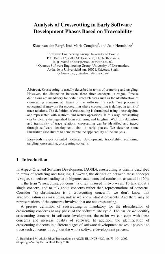
For example, assume we have three concerns shown as elements of a source in Fig. 1, and four requirements (e.g., use cases) shown as elements of a target.
This picture is consistent with the citation at the beginning of the Introduction. Intuitively, we could say that s1 crosscuts s3 for the given relation between source and target elements. In this figure we only show two abstraction levels, but multiple intermediate levels between source and target may exist. This picture also fits other
Analysis of Crosscutting in Early Software Development Phases Based on Traceability 75
s1 s2
t1 t2
s3
t3 t4
source
target
s1 s2
t1 t2
s3
t3 t4
source
target
Fig. 1. Trace relations between source and target elements
intuitive notions of crosscutting, scattering and tangling which we can find in the literature such as “an aspect in requirements is a concern that crosscuts requirements artifacts; an aspect in architecture is a concern that crosscuts architectural artifacts” [6] or “scattering occurs when the design of a single requirement is necessarily scattered across multiple classes and operations in the object-oriented design”, “tangling occurs when a single class or operation in the object-oriented design contains design details of multiple requirements” both in [5]. As we can see in these citations, the notion of crosscutting, scattering and tangling is based on the relationship of elements at two levels or domains, depicted here as source and target. We discuss this in Sect. 6.
In the following section we generalize this intuition by means of a crosscutting pattern. Furthermore, we focus on definitions of crosscutting, tangling and scattering.
2.1 Generalization
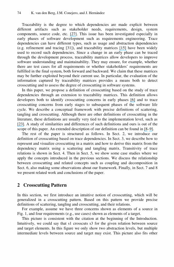
Our proposition is that crosscutting can only be defined in terms of “one thing” with respect to "another thing”. Accordingly and from a mathematical point of view, what this means is that we have two domains related to each other through a mapping. We use here the general terms source and target (as in [24]) to denote these two domains, and the trace relationship is the mapping relating elements in these domains (see Fig. 2).
Fig. 2. Crosscutting pattern
We use the term Crosscutting Pattern to denote the situation where source and target are related to each other through trace dependencies. We use the term pattern as in design patterns [18], in the sense of being a general description of frequently encountered situations [23,25].
76 K. van den Berg, J.M. Conejero, and J. Hernández
Although the terms source and target could represent two different domains, levels or phases of a software development process, we abstract from specific phases such as concern modeling, requirements elicitation, architectural design and so on. The only proposition is that we define crosscutting for two levels, which we called source and target. This approach can be applied to early phases in software development, e.g. concerns and requirements, but also to other phases near implementation, e.g., a UML design and Java code. In each case we have to define the trace relations between the respective source elements and target elements. We show a traceability model in Sect. 6.1 where we discuss the mapping between source and target in more detail.
In Table 1 we show some situations where the crosscutting pattern can be applied, with examples of source and target elements.
Table 1. Some examples of source and target domains
Examples Source Target We may identify
Ex. 1 Concerns Requirements Statements Crosscutting Concerns with respect to mapping to Requirements Statements
Ex. 2 Concerns Use Cases Crosscutting Concerns with respect to mapping to Use Cases
Ex. 3 Concerns Design Modules Crosscutting Concerns with respect to mapping to Design Modules
Ex. 4 Use Cases Architectural Components Crosscutting Use Cases with respect to mapping to Architectural Components
Ex. 5 Use Cases Design Modules Crosscutting Use Cases with respect to mapping to Design Modules
Ex. 6 Design Modules Programming Artifacts Crosscutting Design Modules with respect to mapping to Programming
Artifacts
Ex. 7 PIM artifacts (MDA) PSM artifacts (MDA) Crosscutting in PIM artifacts with respect to mapping to PSM artifacts
The definitions of tangling, scattering and crosscutting are relative to the source and target in the crosscutting pattern. Therefore, scattering, tangling and crosscutting are defined as specific cases of the mapping between source and target. We denote this mapping between source and target as (Source x Target). This is explained in the following section.
2.2 Definitions Based on the Crosscutting Pattern
As we can see in Fig. 2, there is a mapping from source elements to target elements. This mapping from source to target has a multiplicity. In the case of 1:many mappings we have scattering, defined as follows: Scattering occurs when, in a mapping between source and target, a source element is related to multiple target elements. The correspondence between two given domains, source and target, is defined as follows. For s є Source, f(s) = {t є Target / t is related to s in the target domain}. We can define scattering as: An element s є Source is scattered if and only if card(f(s)) > 1, where card is the cardinality. In Fig. 1 we can see how the source element s1 is scattered over the target elements t1, t3 and t4.
Similarly, we can focus on the relation between target elements and source elements. This relation (here also called mapping) is the reverse of the mapping above. In the case of 1:many mappings from target to source we have tangling,
Analysis of Crosscutting in Early Software Development Phases Based on Traceability 77
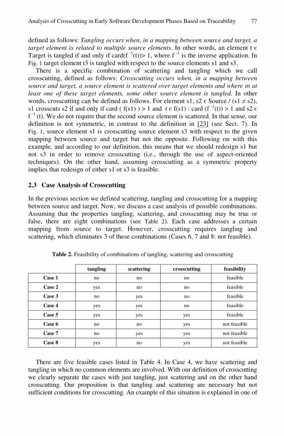
defined as follows: Tangling occurs when, in a mapping between source and target, a target element is related to multiple source elements. In other words, an element t є Target is tangled if and only if card(f -1(t))> 1, where f -1 is the inverse application. In Fig. 1 target element t3 is tangled with respect to the source elements s1 and s3.
There is a specific combination of scattering and tangling which we call crosscutting, defined as follows: Crosscutting occurs when, in a mapping between source and target, a source element is scattered over target elements and where in at least one of these target elements, some other source element is tangled. In other words, crosscutting can be defined as follows. For element s1, s2 є Source / (s1 ≠ s2), s1 crosscuts s2 if and only if card ( f(s1) ) > 1 and t є f(s1) : card (f -1(t)) > 1 and s2 є f -1 (t). We do not require that the second source element is scattered. In that sense, our definition is not symmetric, in contrast to the definition in [23] (see Sect. 7). In Fig. 1, source element s1 is crosscutting source element s3 with respect to the given mapping between source and target but not the opposite. Following on with this example, and according to our definition, this means that we should redesign s1 but not s3 in order to remove crosscutting (i.e., through the use of aspect-oriented techniques). On the other hand, assuming crosscutting as a symmetric property implies that redesign of either s1 or s3 is feasible.
2.3 Case Analysis of Crosscutting
In the previous section we defined scattering, tangling and crosscutting for a mapping between source and target. Now, we discuss a case analysis of possible combinations. Assuming that the properties tangling, scattering, and crosscutting may be true or false, there are eight combinations (see Table 2). Each case addresses a certain mapping from source to target. However, crosscutting requires tangling and scattering, which eliminates 3 of these combinations (Cases 6, 7 and 8: not feasible).
Table 2. Feasibility of combinations of tangling, scattering and crosscutting
tangling scattering crosscutting feasibility
Case 1 no no no feasible
Case 2 yes no no feasible
Case 3 no yes no feasible
Case 4 yes yes no feasible
Case 5 yes yes yes feasible
Case 6 no no yes not feasible
Case 7 no yes yes not feasible
Case 8 yes no yes not feasible
There are five feasible cases listed in Table 4. In Case 4, we have scattering and tangling in which no common elements are involved. With our definition of crosscutting we clearly separate the cases with just tangling, just scattering and on the other hand crosscutting. Our proposition is that tangling and scattering are necessary but not sufficient conditions for crosscutting. An example of this situation is explained in one of
78 K. van den Berg, J.M. Conejero, and J. Hernández
the case studies (Sect. 5.1). We will now describe the representation of trace dependencies in traceability matrices.
3 Matrix Representation of Trace Relations
In this section we show how crosscutting can be represented and identified by means of an extension to traceability matrices. Trace relations are captured in a dependency matrix, representing the mapping between source and target. As an extension, we derive the crosscutting matrix from the dependency matrix. We describe how the crosscutting matrix can be constructed from the dependency matrix with some auxiliary matrices. This is illustrated with some examples.
3.1 Tracing from Source to Target
Traceability matrices have usually been used to show the relationships between requirements elicitation and the representation of these requirements in a particular engineering approach (such as use cases [31] or viewpoints [16]).
In terms of linear algebra, traceability matrices show the mappings between source and target. We show these mappings in a special kind of traceability matrix that we called a dependency matrix. A dependency matrix (source x target) represents the dependency relation between source elements and target elements (inter-level relationship). In the rows we have the source elements, and in the columns we have the target elements. In this matrix a cell with 1 denotes that the source element (in the row) is mapped to the target element (in the column). Reciprocally this means that the target element depends on the source element. Scattering and tangling can easily be visualized in this matrix (see the examples below).
We define a new auxiliary concept crosscutpoint used in the context of dependency matrices to denote a matrix cell involved in both tangling and scattering (see dark grey cell in Table 3). If there are one or more crosscutpoints then we say we have crosscutting.
Crosscutting between source elements for a given mapping to target elements, as shown in a dependency matrix, can be represented in a crosscutting matrix. A crosscutting matrix (source x source) represents the crosscutting relation between source elements for a given source-to-target mapping (represented in a dependency matrix). In the crosscutting matrix, a cell with 1 denotes that the source element in the row is crosscutting the source element in the column. In the next Sect. 3.2, we explain how this crosscutting matrix can be derived from the dependency matrix.
A crosscutting matrix should not be confused with a coupling matrix. A coupling matrix shows coupling relations between elements at the same level of abstraction (intra-level dependencies). In some sense, the coupling matrix is related to the design structure matrix [3]. On the other hand, a crosscutting matrix shows crosscutting relations between elements at one level with respect to a mapping onto elements at some other level (inter-level dependencies).
We now give an example and use the dependency matrix and crosscutting matrix to visualize the definitions (S denotes a scattered source element — a grey row; NS denotes a non-scattered source element; T denotes a tangled target element — a grey column; NT denotes a non-tangled target element). The example is shown in Table 3.
Analysis of Crosscutting in Early Software Development Phases Based on Traceability 79
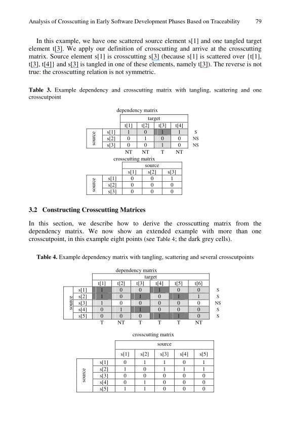
In this example, we have one scattered source element s[1] and one tangled target element t[3]. We apply our definition of crosscutting and arrive at the crosscutting matrix. Source element s[1] is crosscutting s[3] (because s[1] is scattered over {t[1], t[3], t[4]} and s[3] is tangled in one of these elements, namely t[3]). The reverse is not true: the crosscutting relation is not symmetric.
Table 3. Example dependency and crosscutting matrix with tangling, scattering and one crosscutpoint
dependency matrix
target
t[1] t[2] t[3] t[4]
s[1] 1 0 1 1 S
s[2] 0 1 0 0 NS
sour
ce
s[3] 0 0 1 0 NS
NT NT T NT
crosscutting matrix source s[1] s[2] s[3]
s[1] 0 0 1 s[2] 0 0 0
sour
ce
s[3] 0 0 0
3.2 Constructing Crosscutting Matrices
In this section, we describe how to derive the crosscutting matrix from the dependency matrix. We now show an extended example with more than one crosscutpoint, in this example eight points (see Table 4; the dark grey cells).
Table 4. Example dependency matrix with tangling, scattering and several crosscutpoints
dependency matrix
target
t[1] t[2] t[3] t[4] t[5] t[6]
s[1] 1 0 0 1 0 0 S
s[2] 1 0 1 0 1 1 S
s[3] 1 0 0 0 0 0 NS
s[4] 0 1 1 0 0 0 S sour
ce
s[5] 0 0 0 1 1 0 S
T NT T T T NT
crosscutting matrix
source
s[1] s[2] s[3] s[4] s[5]
s[1] 0 1 1 0 1 s[2] 1 0 1 1 1 s[3] 0 0 0 0 0 s[4] 0 1 0 0 0 so
urce
s[5] 1 1 0 0 0
80 K. van den Berg, J.M. Conejero, and J. Hernández
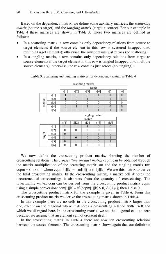
Based on the dependency matrix, we define some auxiliary matrices: the scattering matrix (source x target) and the tangling matrix (target x source). For our example in Table 4 these matrices are shown in Table 5. These two matrices are defined as follows:
• In a scattering matrix, a row contains only dependency relations from source to target elements if the source element in this row is scattered (mapped onto multiple target elements); otherwise, the row contains just zeroes (no scattering).
• In a tangling matrix, a row contains only dependency relations from target to source elements if the target element in this row is tangled (mapped onto multiple source elements); otherwise, the row contains just zeroes (no tangling).
Table 5. Scattering and tangling matrices for dependency matrix in Table 4
scattering matrix target t[1] t[2] t[3] t[4] t[5] t[6]
s[1] 1 0 0 1 0 0 s[2] 1 0 1 0 1 1 s[3] 0 0 0 0 0 0 s[4] 0 1 1 0 0 0 so
urce
s[5] 0 0 0 1 1 0
tangling matrix source s[1] S[2] s[3] s[4] s[5]
t[1] 1 1 1 0 0 t[2] 0 0 0 0 0 t[3] 0 1 0 1 0 t[4] 1 0 0 0 1 t[5] 0 1 0 0 1
targ
et
t[6] 0 0 0 0 0
We now define the crosscutting product matrix, showing the number of crosscutting relations. The crosscutting product matrix ccpm can be obtained through the matrix multiplication of the scattering matrix sm and the tangling matrix tm: ccpm = sm x tm where ccpm [i][k] = sm[i][j] x tm[j][k]. We use this matrix to derive the final crosscutting matrix. In the crosscutting matrix, a matrix cell denotes the occurrence of crosscutting; it abstracts from the quantity of crosscutting. The crosscutting matrix ccm can be derived from the crosscutting product matrix ccpm using a simple conversion: ccm[i][k] = if (ccpm[i][k] > 0) /\ ( i ≠ j) then 1 else 0.
The crosscutting product matrix for the example is given in Table 6. From this crosscutting product matrix we derive the crosscutting matrix shown in Table 4.
In this example there are no cells in the crosscutting product matrix larger than one, except on the diagonal where it denotes a crosscutting relation with itself and which we disregard here. In the crosscutting matrix, we set the diagonal cells to zero because, we assume that an element cannot crosscut itself.
In the crosscutting matrix in Table 4 there are now ten crosscutting relations between the source elements. The crosscutting matrix shows again that our definition
Analysis of Crosscutting in Early Software Development Phases Based on Traceability 81
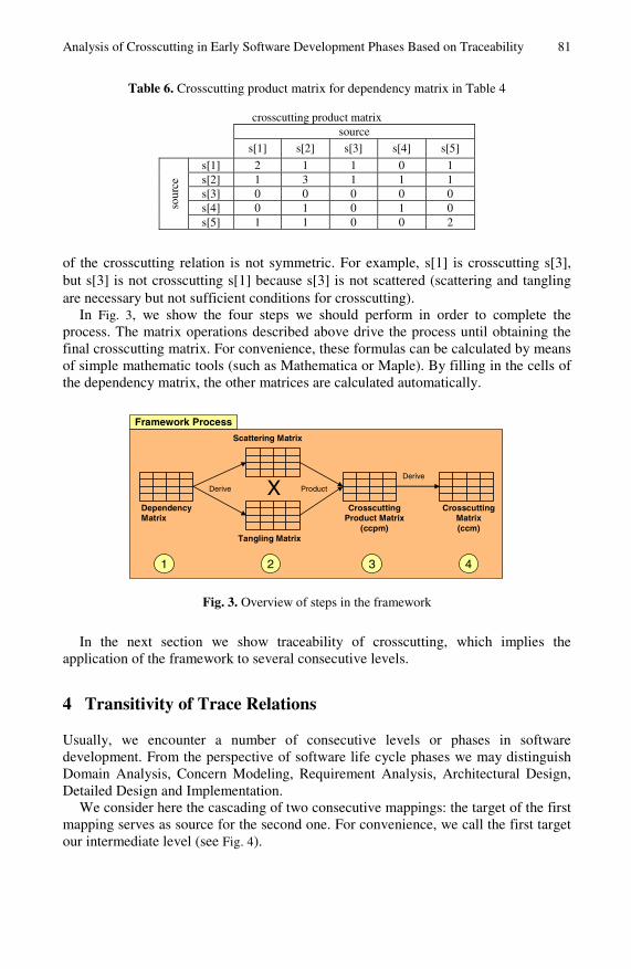
Table 6. Crosscutting product matrix for dependency matrix in Table 4
crosscutting product matrix source s[1] s[2] s[3] s[4] s[5]
s[1] 2 1 1 0 1 s[2] 1 3 1 1 1 s[3] 0 0 0 0 0 s[4] 0 1 0 1 0 so
urce
s[5] 1 1 0 0 2
of the crosscutting relation is not symmetric. For example, s[1] is crosscutting s[3], but s[3] is not crosscutting s[1] because s[3] is not scattered (scattering and tangling are necessary but not sufficient conditions for crosscutting).
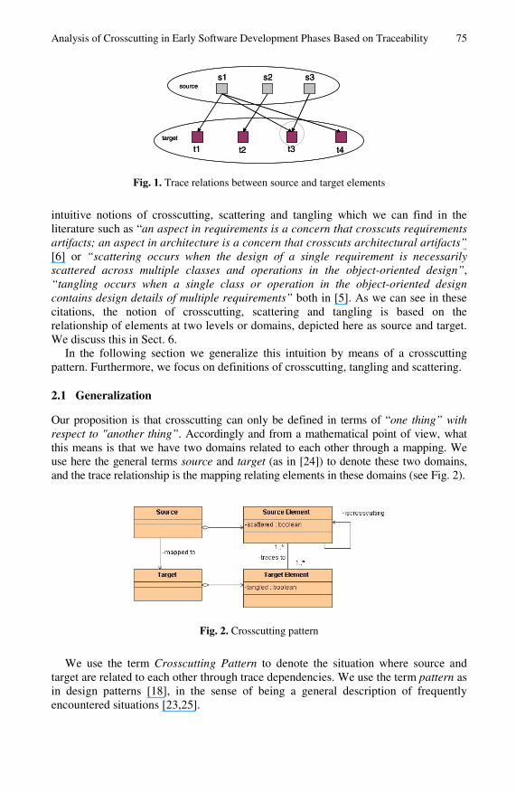
In Fig. 3, we show the four steps we should perform in order to complete the process. The matrix operations described above drive the process until obtaining the final crosscutting matrix. For convenience, these formulas can be calculated by means of simple mathematic tools (such as Mathematica or Maple). By filling in the cells of the dependency matrix, the other matrices are calculated automatically.
1
DependencyMatrix
2
Tangling Matrix
Scattering Matrix
3 4
CrosscuttingProduct Matrix
(ccpm)
CrosscuttingMatrix(ccm)
Derive X Product
Derive
Framework Process
Fig. 3. Overview of steps in the framework
In the next section we show traceability of crosscutting, which implies the application of the framework to several consecutive levels.
4 Transitivity of Trace Relations
Usually, we encounter a number of consecutive levels or phases in software development. From the perspective of software life cycle phases we may distinguish Domain Analysis, Concern Modeling, Requirement Analysis, Architectural Design, Detailed Design and Implementation.
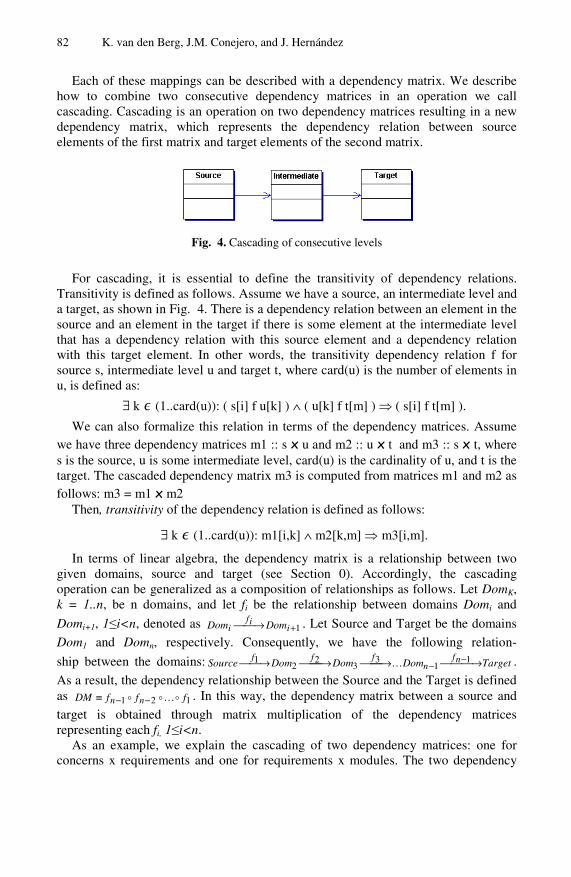
We consider here the cascading of two consecutive mappings: the target of the first mapping serves as source for the second one. For convenience, we call the first target our intermediate level (see Fig. 4).
82 K. van den Berg, J.M. Conejero, and J. Hernández
Each of these mappings can be described with a dependency matrix. We describe how to combine two consecutive dependency matrices in an operation we call cascading. Cascading is an operation on two dependency matrices resulting in a new dependency matrix, which represents the dependency relation between source elements of the first matrix and target elements of the second matrix.
Fig. 4. Cascading of consecutive levels
For cascading, it is essential to define the transitivity of dependency relations. Transitivity is defined as follows. Assume we have a source, an intermediate level and a target, as shown in Fig. 4. There is a dependency relation between an element in the source and an element in the target if there is some element at the intermediate level that has a dependency relation with this source element and a dependency relation with this target element. In other words, the transitivity dependency relation f for source s, intermediate level u and target t, where card(u) is the number of elements in u, is defined as:
∃ k ∊ (1..card(u)): ( s[i] f u[k] ) ∧ ( u[k] f t[m] ) ⇒ ( s[i] f t[m] ).
We can also formalize this relation in terms of the dependency matrices. Assume we have three dependency matrices m1 :: s x u and m2 :: u x t and m3 :: s x t, where s is the source, u is some intermediate level, card(u) is the cardinality of u, and t is the target. The cascaded dependency matrix m3 is computed from matrices m1 and m2 as follows: m3 = m1 x m2
Then, transitivity of the dependency relation is defined as follows:
∃ k ∊ (1..card(u)): m1[i,k] ∧ m2[k,m] ⇒ m3[i,m].
In terms of linear algebra, the dependency matrix is a relationship between two given domains, source and target (see Section 0). Accordingly, the cascading operation can be generalized as a composition of relationships as follows. Let DomK, k = 1..n, be n domains, and let fi be the relationship between domains Domi and
Domi+1, 1≤i<n, denoted as 1+⎯→⎯ iif
i DomDom . Let Source and Target be the domains
Dom1 and Domn, respectively. Consequently, we have the following relation-
ship between the domains: argetTDomDomDom ourceS nfn
fff ⎯⎯ →⎯⎯⎯→⎯⎯⎯→⎯⎯→⎯ −−
11
33
22
1 … .
As a result, the dependency relationship between the Source and the Target is defined as 121 fffDM nn …−−≡ . In this way, the dependency matrix between a source and
target is obtained through matrix multiplication of the dependency matrices representing each fi, 1≤i<n.
As an example, we explain the cascading of two dependency matrices: one for concerns x requirements and one for requirements x modules. The two dependency
Analysis of Crosscutting in Early Software Development Phases Based on Traceability 83
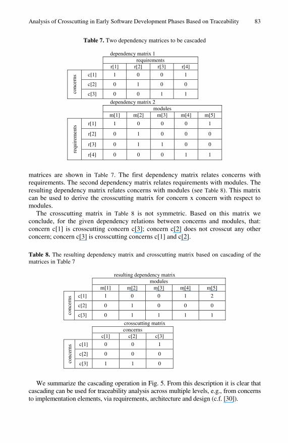
Table 7. Two dependency matrices to be cascaded
dependency matrix 1 requirements r[1] r[2] r[3] r[4]
c[1] 1 0 0 1
c[2] 0 1 0 0
conc
erns
c[3] 0 0 1 1
dependency matrix 2 modules m[1] m[2] m[3] m[4] m[5]
r[1] 1 0 0 0 1
r[2] 0 1 0 0 0
r[3] 0 1 1 0 0
requ
irem
ents
r[4] 0 0 0 1 1
matrices are shown in Table 7. The first dependency matrix relates concerns with requirements. The second dependency matrix relates requirements with modules. The resulting dependency matrix relates concerns with modules (see Table 8). This matrix can be used to derive the crosscutting matrix for concern x concern with respect to modules.
The crosscutting matrix in Table 8 is not symmetric. Based on this matrix we conclude, for the given dependency relations between concerns and modules, that: concern c[1] is crosscutting concern c[3]; concern c[2] does not crosscut any other concern; concern c[3] is crosscutting concerns c[1] and c[2].
Table 8. The resulting dependency matrix and crosscutting matrix based on cascading of the matrices in Table 7
resulting dependency matrix modules m[1] m[2] m[3] m[4] m[5]
c[1] 1 0 0 1 2
c[2] 0 1 0 0 0
conc
erns
c[3] 0 1 1 1 1
crosscutting matrix concerns c[1] c[2] c[3]
c[1] 0 0 1
c[2] 0 0 0
conc
erns
c[3] 1 1 0
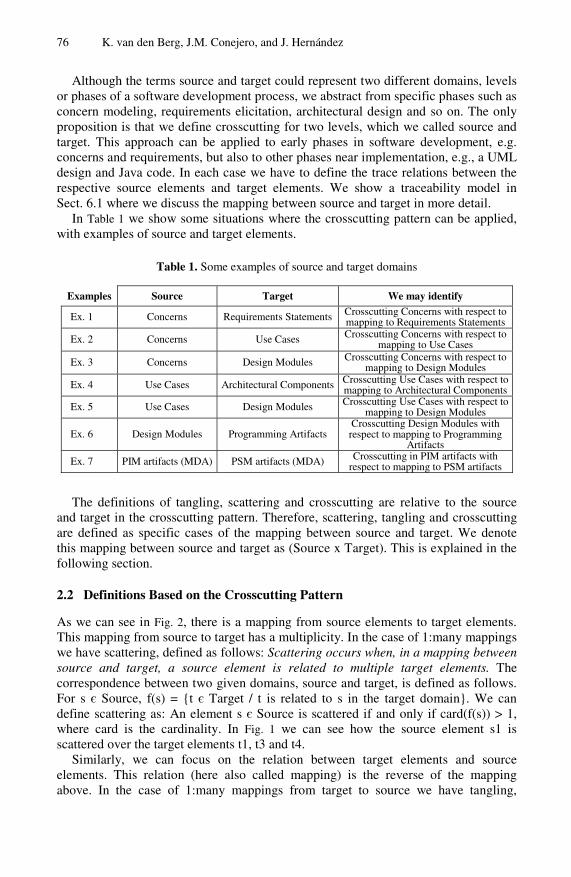
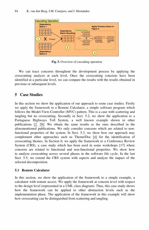
We summarize the cascading operation in Fig. 5. From this description it is clear that cascading can be used for traceability analysis across multiple levels, e.g., from concerns to implementation elements, via requirements, architecture and design (c.f. [30]).
84 K. van den Berg, J.M. Conejero, and J. Hernández
1
DependencyMatrix 1
2
X Product
Cascading Operation
DependencyMatrix 2
DependencyMatrix Resulting
Apply Process shown in Figure 4
2
Tangling Matrix
Scattering Matrix
3 4
CrosscuttingProduct Matrix
CrosscuttingMatrix
Derive X Product
Derive
Framework Process
3
Fig. 5. Overview of cascading operation
We can trace concerns throughout the development process by applying the crosscutting analysis at each level. Once the crosscutting concerns have been identified at a particular level, we can compare the results with the results obtained in previous or subsequent levels.
5 Case Studies
In this section we show the application of our approach to some case studies. Firstly we apply the framework to a Remote Calculator, a simple software program which follows the Model-View-Controller (MVC) pattern. This is a case with scattering and tangling but no crosscutting. Secondly in Sect. 5.2, we show the application to a Portuguese Highways Toll System, a well known example shown in other publications [2, 28]. We obtain the same results as the ones described in the aforementioned publications. We only consider concerns which are related to non-functional properties of the system. In Sect. 5.3, we show how our approach may complement other approaches such us Theme/Doc [4] for the identification of crosscutting themes. In Section 0, we apply the framework to a Conference Review System (CRS), a case study which has been used in some workshops [17] where concerns are related to functional and non-functional properties. We show how to analyze crosscutting across several phases in the software life cycle. In the last Sect. 5.5, we extend the CRS system with aspects and analyze the impact of the selected decomposition.
5.1 Remote Calculator
In this section, we show the application of the framework to a simple example, a calculator with remote access. We apply the framework at concern level with respect to the design level (represented in a UML class diagram). Thus, this case study shows how the framework can be applied to other abstraction levels such as the implementation phase. The application of the framework in this example will show how crosscutting can be distinguished from scattering and tangling.
Analysis of Crosscutting in Early Software Development Phases Based on Traceability 85
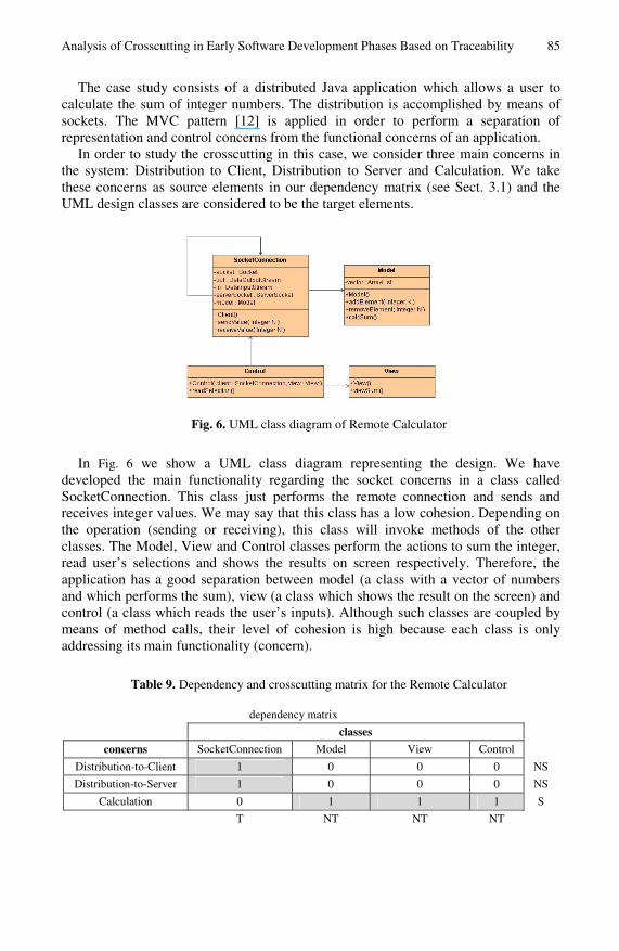
The case study consists of a distributed Java application which allows a user to calculate the sum of integer numbers. The distribution is accomplished by means of sockets. The MVC pattern [12] is applied in order to perform a separation of representation and control concerns from the functional concerns of an application.
In order to study the crosscutting in this case, we consider three main concerns in the system: Distribution to Client, Distribution to Server and Calculation. We take these concerns as source elements in our dependency matrix (see Sect. 3.1) and the UML design classes are considered to be the target elements.
Fig. 6. UML class diagram of Remote Calculator
In Fig. 6 we show a UML class diagram representing the design. We have developed the main functionality regarding the socket concerns in a class called SocketConnection. This class just performs the remote connection and sends and receives integer values. We may say that this class has a low cohesion. Depending on the operation (sending or receiving), this class will invoke methods of the other classes. The Model, View and Control classes perform the actions to sum the integer, read user’s selections and shows the results on screen respectively. Therefore, the application has a good separation between model (a class with a vector of numbers and which performs the sum), view (a class which shows the result on the screen) and control (a class which reads the user’s inputs). Although such classes are coupled by means of method calls, their level of cohesion is high because each class is only addressing its main functionality (concern).
Table 9. Dependency and crosscutting matrix for the Remote Calculator
dependency matrix
classes
concerns SocketConnection Model View Control
Distribution-to-Client 1 0 0 0 NS
Distribution-to-Server 1 0 0 0 NS
Calculation 0 1 1 1 S
T NT NT NT
86 K. van den Berg, J.M. Conejero, and J. Hernández
Table 9. (continued)
crosscutting matrix WRT1 classes
concerns
concerns Distribution-to-
Client Distribution-
to-Server Calculation
Distribution-to-Client 0 0 0
Distribution-to-Server 0 0 0
Calculation 0 0 0
1 WRT are the abbreviation of “with respect to”.
So, taking such a decomposition (in classes) and applying the framework, we obtain the dependency matrix shown in Table 9. As we can see in the matrix, concerns Distribution-to-Client and Distribution-to-Server are tangled in the same class SocketConnection, whereas Calculation concern is scattered over the other classes. However, as can be seen in the table, the matrix has no crosscutpoint. By means of the operations described in Sect. 3.2 we obtain the crosscutting matrix shown in Table 9: there are no crosscutting concerns in the system.
In many situations, we have tangling, scattering and at the same time crosscutting. With our definitions, we clearly distinguished scattering and tangling from crosscutting and, as we stated in Sect. 2.3, scattering and tangling are necessary but not sufficient conditions for crosscutting. The analysis depends on the chosen decomposition of source and target, other decompositions being feasible.
5.2 Portuguese Highways Toll System
In order to validate our framework, in this section we apply it to a well-known case study — the Portuguese Highways Toll System — which has been widely explained in some publications on the early aspects topic [2, 28]. As we will see at the end of the section, the results obtained are similar. As a starting point we take the same decompositions made by the authors of the original case. It can be seen that the concern decomposition is related to non-functional properties of the system.
The system is based on a road traffic price system where drivers of authorized vehicles are charged automatically at toll gates. The gates have sensors able to read information provided by a device installed in the vehicle when it passes through. This device is called a “gizmo” [28]. When an authorized vehicle passes through the toll gate, a green light turns on and a display shows the amount to be paid by the driver. If the car is not authorized, a yellow light turns on and a camera takes a photo of the license plate.
In [28] the authors identified the following stakeholders’ requirements (which are represented by means of viewpoints [16]): ATM (allows the drivers to enter their information for registration in the system), Vehicle, Gizmo, Police (receives information about unauthorised vehicles), Debiting System (interacts with the bank to allow the payment), Toll Gate, Vehicle Owner and System Administrator (modifies information in the system). Some of these viewpoints have sub-viewpoints. On the other hand, after analyzing the initial requirements the authors specified the following concerns: Security, Response Time, Multi-Access System, Compatibility, Legal Issues, Correctness and Availability.
Analysis of Crosscutting in Early Software Development Phases Based on Traceability 87
Table 10. Dependency matrix for Portuguese Highways Toll System
viewpoints (P:Police, Gz:Gizmo, DS:Debiting system, TG:Toll Gate, PT: Paying Toll, ST:Single Toll, ExT:Exit Toll, ET:Entry Toll, Vh:Vehicle, UV: Unauthorised Vehicle, VO:Vehicle Owner,
Act:Activation, Reg:Registration, Bill:Billing, Adm:Administration)
concerns P Gz DS ATM TG PT ST ExT ET Vh UV VO Reg Act Bill Adm Response
Time 0 1 0 1 1 1 1 1 1 1 1 0 0 0 0 0
Availability 0 1 0 1 1 1 1 1 1 0 0 0 1 1 0 1
Security 1 0 1 1 0 0 0 0 0 0 0 1 1 1 1 1
Legal Issues 1 0 0 0 0 0 0 1 0 0 0 0 1 0 1 0
Compatibility 1 0 1 1 0 0 0 0 0 0 0 0 0 1 0 0
Correctness 1 1 1 0 1 1 1 1 1 0 0 1 1 1 1 0
Multi-Access 0 1 0 1 1 1 1 1 1 1 1 0 1 1 0 0
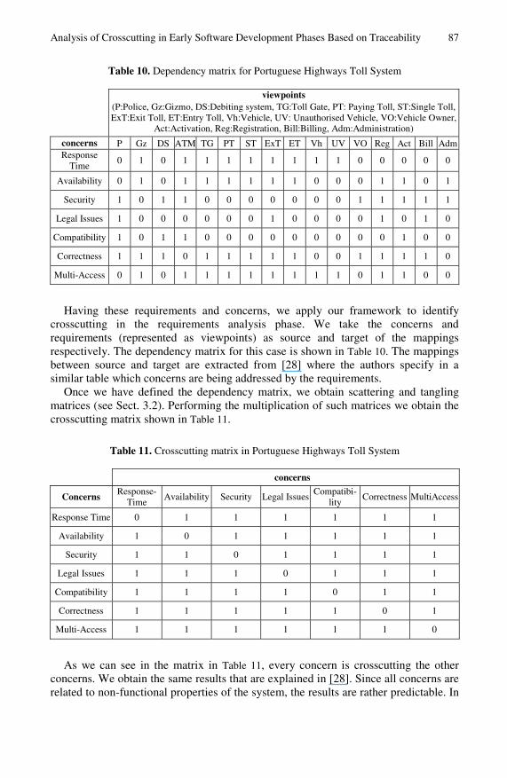
Having these requirements and concerns, we apply our framework to identify crosscutting in the requirements analysis phase. We take the concerns and requirements (represented as viewpoints) as source and target of the mappings respectively. The dependency matrix for this case is shown in Table 10. The mappings between source and target are extracted from [28] where the authors specify in a similar table which concerns are being addressed by the requirements.
Once we have defined the dependency matrix, we obtain scattering and tangling matrices (see Sect. 3.2). Performing the multiplication of such matrices we obtain the crosscutting matrix shown in Table 11.
Table 11. Crosscutting matrix in Portuguese Highways Toll System
concerns
Concerns Response-
Time Availability Security Legal Issues
Compatibi-lity
Correctness MultiAccess
Response Time 0 1 1 1 1 1 1
Availability 1 0 1 1 1 1 1
Security 1 1 0 1 1 1 1
Legal Issues 1 1 1 0 1 1 1
Compatibility 1 1 1 1 0 1 1
Correctness 1 1 1 1 1 0 1
Multi-Access 1 1 1 1 1 1 0
As we can see in the matrix in Table 11, every concern is crosscutting the other concerns. We obtain the same results that are explained in [28]. Since all concerns are related to non-functional properties of the system, the results are rather predictable. In
88 K. van den Berg, J.M. Conejero, and J. Hernández
order to make a more realistic study of crosscutting in systems, both concerns related to functional and non-functional properties must be analyzed. Otherwise, we obtain results where every concern is crosscutting the other concerns as shown in this case.
5.3 Course Management System
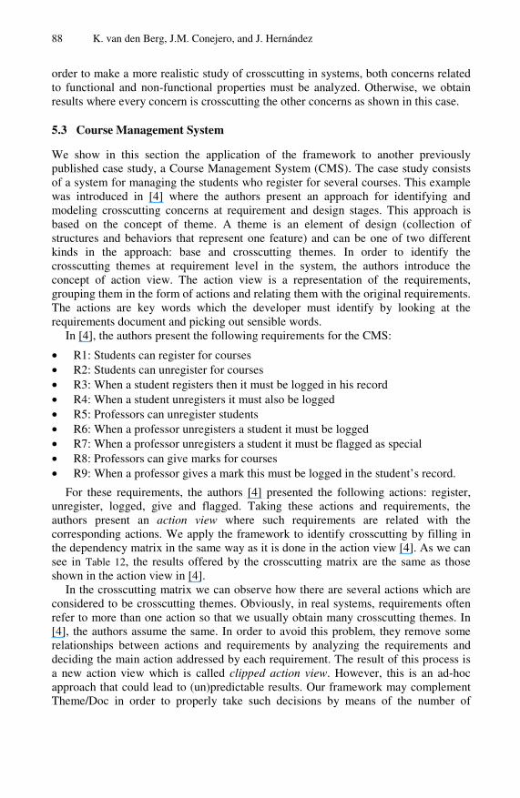
We show in this section the application of the framework to another previously published case study, a Course Management System (CMS). The case study consists of a system for managing the students who register for several courses. This example was introduced in [4] where the authors present an approach for identifying and modeling crosscutting concerns at requirement and design stages. This approach is based on the concept of theme. A theme is an element of design (collection of structures and behaviors that represent one feature) and can be one of two different kinds in the approach: base and crosscutting themes. In order to identify the crosscutting themes at requirement level in the system, the authors introduce the concept of action view. The action view is a representation of the requirements, grouping them in the form of actions and relating them with the original requirements. The actions are key words which the developer must identify by looking at the requirements document and picking out sensible words.
In [4], the authors present the following requirements for the CMS:
• R1: Students can register for courses • R2: Students can unregister for courses • R3: When a student registers then it must be logged in his record • R4: When a student unregisters it must also be logged • R5: Professors can unregister students • R6: When a professor unregisters a student it must be logged • R7: When a professor unregisters a student it must be flagged as special • R8: Professors can give marks for courses • R9: When a professor gives a mark this must be logged in the student’s record.
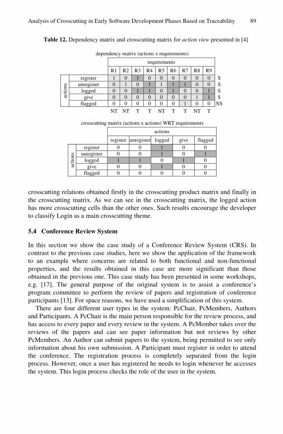
For these requirements, the authors [4] presented the following actions: register, unregister, logged, give and flagged. Taking these actions and requirements, the authors present an action view where such requirements are related with the corresponding actions. We apply the framework to identify crosscutting by filling in the dependency matrix in the same way as it is done in the action view [4]. As we can see in Table 12, the results offered by the crosscutting matrix are the same as those shown in the action view in [4].
In the crosscutting matrix we can observe how there are several actions which are considered to be crosscutting themes. Obviously, in real systems, requirements often refer to more than one action so that we usually obtain many crosscutting themes. In [4], the authors assume the same. In order to avoid this problem, they remove some relationships between actions and requirements by analyzing the requirements and deciding the main action addressed by each requirement. The result of this process is a new action view which is called clipped action view. However, this is an ad-hoc approach that could lead to (un)predictable results. Our framework may complement Theme/Doc in order to properly take such decisions by means of the number of
Analysis of Crosscutting in Early Software Development Phases Based on Traceability 89
Table 12. Dependency matrix and crosscutting matrix for action view presented in [4]
dependency matrix (actions x requirements)
requirements
R1 R2 R3 R4 R5 R6 R7 R8 R9
register 1 0 1 0 0 0 0 0 0 S unregister 0 1 0 1 1 1 1 0 0 S
logged 0 0 1 1 0 1 0 0 1 S give 0 0 0 0 0 0 0 1 1 S ac
tions
flagged 0 0 0 0 0 0 1 0 0 NS
NT NT T T NT T T NT T
crosscutting matrix (actions x actions) WRT requirements
actions
register unregister logged give flagged
register 0 0 1 0 0 unregister 0 0 1 0 1
logged 1 1 0 1 0 give 0 0 1 0 0 ac
tions
flagged 0 0 0 0 0
crosscutting relations obtained firstly in the crosscutting product matrix and finally in the crosscutting matrix. As we can see in the crosscutting matrix, the logged action has more crosscutting cells than the other ones. Such results encourage the developer to classify Login as a main crosscutting theme.
5.4 Conference Review System
In this section we show the case study of a Conference Review System (CRS). In contrast to the previous case studies, here we show the application of the framework to an example where concerns are related to both functional and non-functional properties, and the results obtained in this case are more significant than those obtained in the previous one. This case study has been presented in some workshops, e.g. [17]. The general purpose of the original system is to assist a conference’s program committee to perform the review of papers and registration of conference participants [13]. For space reasons, we have used a simplification of this system.
There are four different user types in the system: PcChair, PcMembers, Authors and Participants. A PcChair is the main person responsible for the review process, and has access to every paper and every review in the system. A PcMember takes over the reviews of the papers and can see paper information but not reviews by other PcMembers. An Author can submit papers to the system, being permitted to see only information about his own submission. A Participant must register in order to attend the conference. The registration process is completely separated from the login process. However, once a user has registered he needs to login whenever he accesses the system. This login process checks the role of the user in the system.
90 K. van den Berg, J.M. Conejero, and J. Hernández
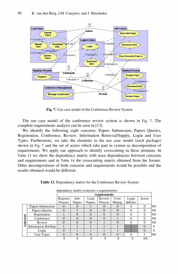
Fig. 7. Use case model of the Conference Review System
The use case model of the conference review system is shown in Fig. 7. The complete requirements analysis can be seen in [13].
We identify the following eight concerns: Papers Submission, Papers Queries, Registration, Conference, Review, Information Retrieval/Supply, Login and User Types. Furthermore, we take the elements in the use case model (each package) shown in Fig. 7 and the set of actors which take part in system as decomposition of requirements. We apply our approach to identify crosscutting in these domains. In Table 13 we show the dependency matrix with trace dependencies between concerns and requirements and in Table 14 the crosscutting matrix obtained from the former. Other decompositions of both concerns and requirements would be possible and the results obtained would be different.
Table 13. Dependency matrix for the Conference Review System
dependency matrix (concerns x requirements) requirements Register
Process Info
Papers Load
Papers Review Process
Conf. Manag.
Login &Roles
Actors
Papers Submission 0 0 1 0 0 0 0 NS Papers Queries 0 1 0 0 0 0 0 NS
Registration 1 0 0 0 0 0 0 NS Conference 0 0 0 0 1 0 0 NS
Review 0 0 0 1 0 0 0 NS Information Ret/Sup 1 1 1 1 1 1 0 S
Login 0 1 1 1 1 1 0 S
conc
erns
User Types 0 0 0 0 0 0 1 NS T T T T T T NT
Analysis of Crosscutting in Early Software Development Phases Based on Traceability 91
Table 14. Crosscutting matrix for the Conference Review System
crosscutting matrix (concerns x concerns) WRT requirements concerns
Papers
Submis-sion
Papers Queries
Registra_tion
Confe-rence
ReviewInformati
on Ret/Sup
Login User
Types
Papers Submission 0 0 0 0 0 0 0 0 Papers Queries 0 0 0 0 0 0 0 0
Registration 0 0 0 0 0 0 0 0 Conference 0 0 0 0 0 0 0 0
Review 0 0 0 0 0 0 0 0 Information Ret/Sup 1 1 1 1 1 0 1 0
Login 1 1 0 1 1 1 0 0
conc
erns
User Types 0 0 0 0 0 0 0 0
As we can see in Table 14, the Login concern crosscuts every concern where the user must authenticate himself and the system must check the role of such user. Similarly, the Information Retrieval/Supply concern crosscuts the concerns which need an access to the correspondence information to perform their actions.
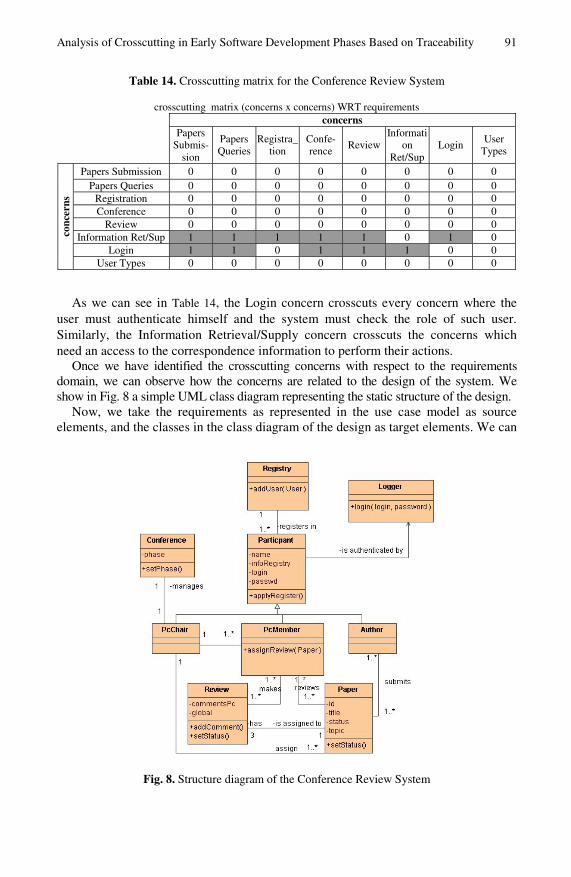
Once we have identified the crosscutting concerns with respect to the requirements domain, we can observe how the concerns are related to the design of the system. We show in Fig. 8 a simple UML class diagram representing the static structure of the design.
Now, we take the requirements as represented in the use case model as source elements, and the classes in the class diagram of the design as target elements. We can
Fig. 8. Structure diagram of the Conference Review System
92 K. van den Berg, J.M. Conejero, and J. Hernández
Table 15. Dependency matrix (requirements x classes) for CRS
classes
Paper Review Confe-rence
Pc Chair
Pc Member
AuthorPartici-
pant Logger Registry
Register Process 0 0 0 0 0 0 1 0 1 S
Info Papers 1 0 0 0 0 0 0 0 0 NS
Load Papers 1 0 0 0 0 0 0 0 0 NS
Review Process 0 1 0 0 0 0 0 0 0 NS
Conf. Manag 0 0 1 0 0 0 0 0 0 NS
Login&Roles 0 0 0 0 0 0 1 1 0 S requ
irem
ents
Actors 0 0 0 1 1 1 1 0 0 S T NT NT NT NT NT T NT NT
build the dependency matrix shown in Table 15 to show the trace dependencies between requirements and design elements.
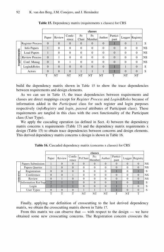
As we can see in Table 15, the trace dependencies between requirements and classes are direct mappings except for Register Process and Login&Roles because of information added in the Participant class for such register and login purposes respectively (infoRegistry and login, passwd attributes of Participant class). These requirements are tangled in this class with the own functionality of the Participant class (User Type).
We apply the cascading operation (as defined in Sect. 4) between the dependency matrix concerns x requirements (Table 13) and the dependency matrix requirements x design (Table 15) to obtain trace dependencies between concerns and design elements. This derived dependency matrix concerns x design is shown in Table 16.
Table 16. Cascaded dependency matrix (concerns x classes) for CRS
classes
concerns
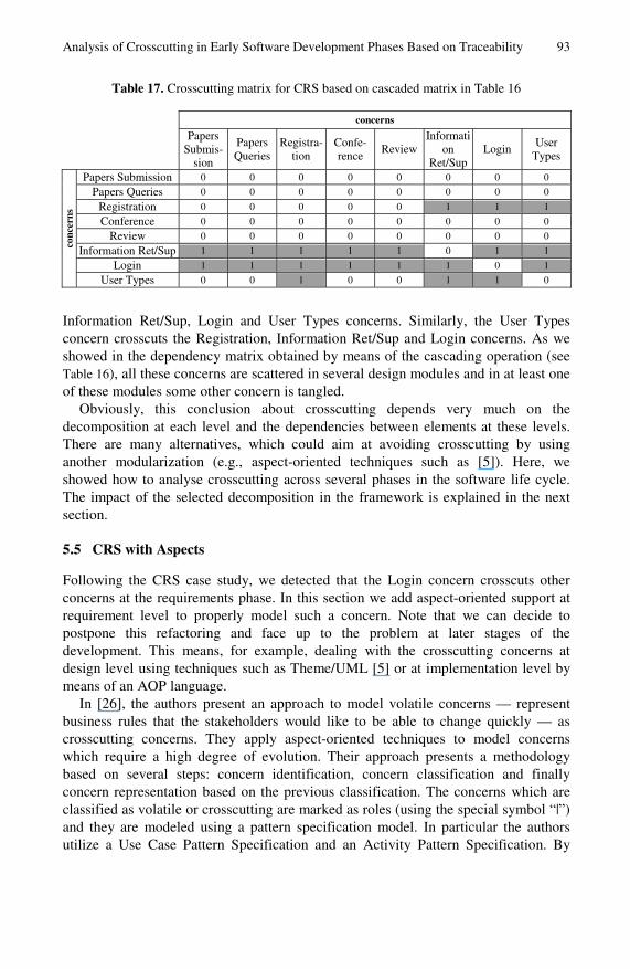
Finally, applying our definition of crosscutting to the last derived dependency matrix, we obtain the crosscutting matrix shown in Table 17.
From this matrix we can observe that — with respect to the design — we have obtained some new crosscutting concerns. The Registration concern crosscuts the
Analysis of Crosscutting in Early Software Development Phases Based on Traceability 93
Table 17. Crosscutting matrix for CRS based on cascaded matrix in Table 16
concerns
Papers
Submis-sion
Papers Queries
Registra-tion
Confe-rence
Review Informati
on Ret/Sup
Login User
Types
Papers Submission 0 0 0 0 0 0 0 0
Papers Queries 0 0 0 0 0 0 0 0
Registration 0 0 0 0 0 1 1 1
Conference 0 0 0 0 0 0 0 0
Review 0 0 0 0 0 0 0 0
Information Ret/Sup 1 1 1 1 1 0 1 1
Login 1 1 1 1 1 1 0 1
conc
erns
User Types 0 0 1 0 0 1 1 0
Information Ret/Sup, Login and User Types concerns. Similarly, the User Types concern crosscuts the Registration, Information Ret/Sup and Login concerns. As we showed in the dependency matrix obtained by means of the cascading operation (see Table 16), all these concerns are scattered in several design modules and in at least one of these modules some other concern is tangled.
Obviously, this conclusion about crosscutting depends very much on the decomposition at each level and the dependencies between elements at these levels. There are many alternatives, which could aim at avoiding crosscutting by using another modularization (e.g., aspect-oriented techniques such as [5]). Here, we showed how to analyse crosscutting across several phases in the software life cycle. The impact of the selected decomposition in the framework is explained in the next section.
5.5 CRS with Aspects
Following the CRS case study, we detected that the Login concern crosscuts other concerns at the requirements phase. In this section we add aspect-oriented support at requirement level to properly model such a concern. Note that we can decide to postpone this refactoring and face up to the problem at later stages of the development. This means, for example, dealing with the crosscutting concerns at design level using techniques such as Theme/UML [5] or at implementation level by means of an AOP language.
In [26], the authors present an approach to model volatile concerns — represent business rules that the stakeholders would like to be able to change quickly — as crosscutting concerns. They apply aspect-oriented techniques to model concerns which require a high degree of evolution. Their approach presents a methodology based on several steps: concern identification, concern classification and finally concern representation based on the previous classification. The concerns which are classified as volatile or crosscutting are marked as roles (using the special symbol “|”) and they are modeled using a pattern specification model. In particular the authors utilize a Use Case Pattern Specification and an Activity Pattern Specification. By
94 K. van den Berg, J.M. Conejero, and J. Hernández
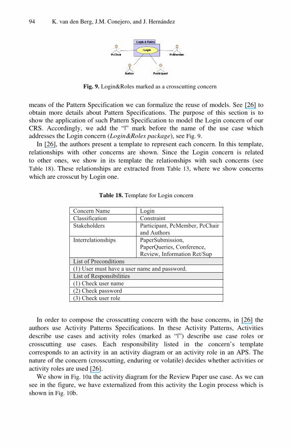
Fig. 9. Login&Roles marked as a crosscutting concern
means of the Pattern Specification we can formalize the reuse of models. See [26] to obtain more details about Pattern Specifications. The purpose of this section is to show the application of such Pattern Specification to model the Login concern of our CRS. Accordingly, we add the “|” mark before the name of the use case which addresses the Login concern (Login&Roles package), see Fig. 9.
In [26], the authors present a template to represent each concern. In this template, relationships with other concerns are shown. Since the Login concern is related to other ones, we show in its template the relationships with such concerns (see Table 18). These relationships are extracted from Table 13, where we show concerns which are crosscut by Login one.
Table 18. Template for Login concern
In order to compose the crosscutting concern with the base concerns, in [26] the authors use Activity Patterns Specifications. In these Activity Patterns, Activities describe use cases and activity roles (marked as “|”) describe use case roles or crosscutting use cases. Each responsibility listed in the concern’s template corresponds to an activity in an activity diagram or an activity role in an APS. The nature of the concern (crosscutting, enduring or volatile) decides whether activities or activity roles are used [26].
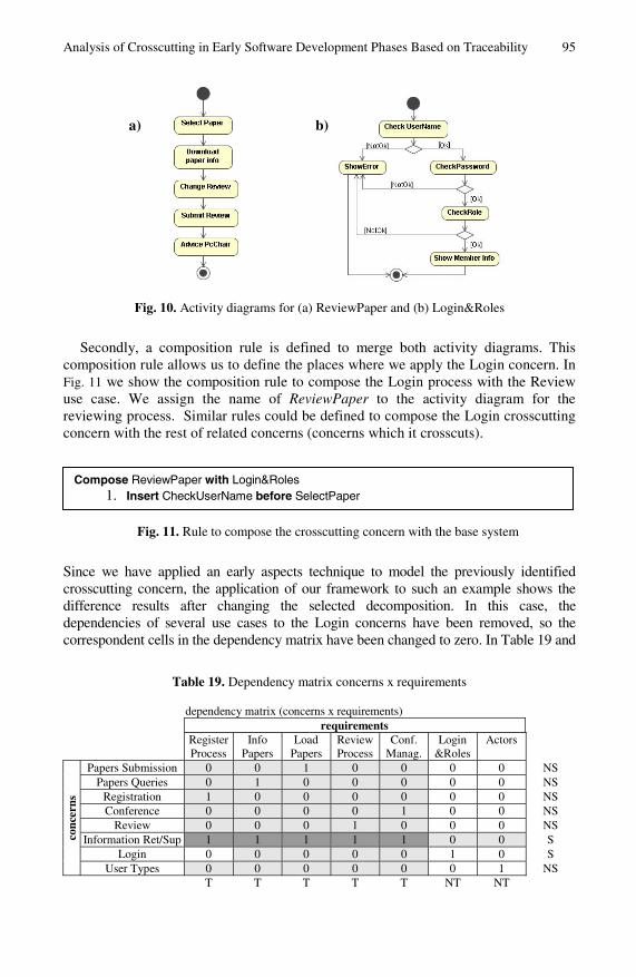
We show in Fig. 10a the activity diagram for the Review Paper use case. As we can see in the figure, we have externalized from this activity the Login process which is shown in Fig. 10b.
Analysis of Crosscutting in Early Software Development Phases Based on Traceability 95
Fig. 10. Activity diagrams for (a) ReviewPaper and (b) Login&Roles
Secondly, a composition rule is defined to merge both activity diagrams. This composition rule allows us to define the places where we apply the Login concern. In Fig. 11 we show the composition rule to compose the Login process with the Review use case. We assign the name of ReviewPaper to the activity diagram for the reviewing process. Similar rules could be defined to compose the Login crosscutting concern with the rest of related concerns (concerns which it crosscuts).
Fig. 11. Rule to compose the crosscutting concern with the base system
Since we have applied an early aspects technique to model the previously identified crosscutting concern, the application of our framework to such an example shows the difference results after changing the selected decomposition. In this case, the dependencies of several use cases to the Login concerns have been removed, so the correspondent cells in the dependency matrix have been changed to zero. In Table 19 and
Table 19. Dependency matrix concerns x requirements
dependency matrix (concerns x requirements) requirements Register
Process Info
Papers Load
Papers Review Process
Conf. Manag.
Login &Roles
Actors
Papers Submission 0 0 1 0 0 0 0 NS Papers Queries 0 1 0 0 0 0 0 NS
Registration 1 0 0 0 0 0 0 NS Conference 0 0 0 0 1 0 0 NS
Review 0 0 0 1 0 0 0 NS Information Ret/Sup 1 1 1 1 1 0 0 S
Login 0 0 0 0 0 1 0 S
conc
erns
User Types 0 0 0 0 0 0 1 NS T T T T T NT NT
Compose ReviewPaper with Login&Roles 1. Insert CheckUserName before SelectPaper
a) b)
96 K. van den Berg, J.M. Conejero, and J. Hernández
Table 20. Crosscutting matrix for CRS with aspects
crosscutting matrix (concerns x concerns) WRT requirements concerns
Papers
Submis-sion
Papers Queries
Registra-tion
Confe-rence
ReviewInforma-
tion Ret/Sup
Login User
Types
Papers Submission 0 0 0 0 0 0 0 0 Papers Queries 0 0 0 0 0 0 0 0
Registration 0 0 0 0 0 0 0 0 Conference 0 0 0 0 0 0 0 0
Review 0 0 0 0 0 0 0 0 Information Ret/Sup 1 1 1 1 1 0 0 0
Login 0 0 0 0 0 0 0 0 User Types 0 0 0 0 0 0 0 0
Table 20 we can observe the dependency and crosscutting matrix for concerns with respect to requirements for the aspect-oriented decomposition respectively. As we can see in these tables, the Login concern does not crosscut the other concerns anymore.
6 Discussion
In this section, we consider how to address some open issues according to our framework. In some cases, there could be better solutions to be considered; however, the main purpose of this section is to enhance the discussion about the following topics. We first analyze some trace dependency types which can be used in the crosscutting pattern. Then, we discuss how crosscutting is related to decompositions expressed in modeling or implementation languages. We conclude our discussion with the role of intra-level dependencies (coupling) for the transitivity of trace relations.
6.1 Trace Relationships
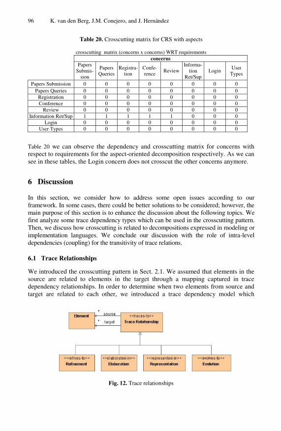
We introduced the crosscutting pattern in Sect. 2.1. We assumed that elements in the source are related to elements in the target through a mapping captured in trace dependency relationships. In order to determine when two elements from source and target are related to each other, we introduced a trace dependency model which
Fig. 12. Trace relationships
Analysis of Crosscutting in Early Software Development Phases Based on Traceability 97
enhances the identification of such relations (see Fig. 12). Ramesh and Jarke [27] show a more detailed model about traceability where these and other more specific relations are explained. The UML 2.0 specification [31] also covers such relationships. In [19] the authors show another taxonomy of trace relationships. The model shown in Fig. 12 is based on the previous models covering some important trace relationships of interest for crosscutting identification.
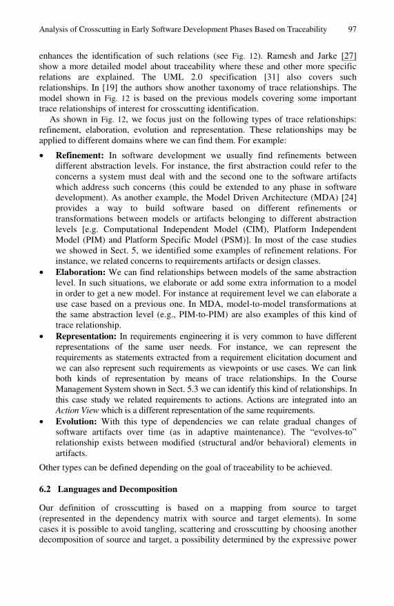
As shown in Fig. 12, we focus just on the following types of trace relationships: refinement, elaboration, evolution and representation. These relationships may be applied to different domains where we can find them. For example:
• Refinement: In software development we usually find refinements between different abstraction levels. For instance, the first abstraction could refer to the concerns a system must deal with and the second one to the software artifacts which address such concerns (this could be extended to any phase in software development). As another example, the Model Driven Architecture (MDA) [24] provides a way to build software based on different refinements or transformations between models or artifacts belonging to different abstraction levels [e.g. Computational Independent Model (CIM), Platform Independent Model (PIM) and Platform Specific Model (PSM)]. In most of the case studies we showed in Sect. 5, we identified some examples of refinement relations. For instance, we related concerns to requirements artifacts or design classes.
• Elaboration: We can find relationships between models of the same abstraction level. In such situations, we elaborate or add some extra information to a model in order to get a new model. For instance at requirement level we can elaborate a use case based on a previous one. In MDA, model-to-model transformations at the same abstraction level (e.g., PIM-to-PIM) are also examples of this kind of trace relationship.
• Representation: In requirements engineering it is very common to have different representations of the same user needs. For instance, we can represent the requirements as statements extracted from a requirement elicitation document and we can also represent such requirements as viewpoints or use cases. We can link both kinds of representation by means of trace relationships. In the Course Management System shown in Sect. 5.3 we can identify this kind of relationships. In this case study we related requirements to actions. Actions are integrated into an Action View which is a different representation of the same requirements.
• Evolution: With this type of dependencies we can relate gradual changes of software artifacts over time (as in adaptive maintenance). The “evolves-to” relationship exists between modified (structural and/or behavioral) elements in artifacts.
Other types can be defined depending on the goal of traceability to be achieved.
6.2 Languages and Decomposition
Our definition of crosscutting is based on a mapping from source to target (represented in the dependency matrix with source and target elements). In some cases it is possible to avoid tangling, scattering and crosscutting by choosing another decomposition of source and target, a possibility determined by the expressive power
98 K. van den Berg, J.M. Conejero, and J. Hernández
of the languages in which the source and target are represented. The expressivity of languages is the leading theme in the seminal paper on aspect-oriented programming by Kiczales et al. [21]. This is also stated in [25]:
Crosscutting models are themselves not the problem. The problem is that our languages and decomposition techniques do not properly support crosscutting modularity.
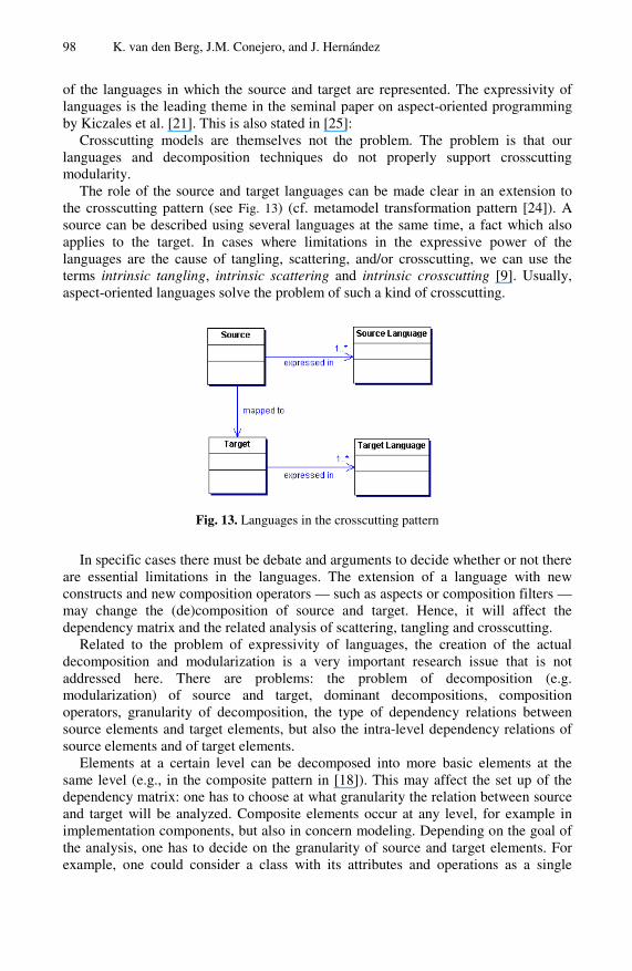
The role of the source and target languages can be made clear in an extension to the crosscutting pattern (see Fig. 13) (cf. metamodel transformation pattern [24]). A source can be described using several languages at the same time, a fact which also applies to the target. In cases where limitations in the expressive power of the languages are the cause of tangling, scattering, and/or crosscutting, we can use the terms intrinsic tangling, intrinsic scattering and intrinsic crosscutting [9]. Usually, aspect-oriented languages solve the problem of such a kind of crosscutting.
Fig. 13. Languages in the crosscutting pattern
In specific cases there must be debate and arguments to decide whether or not there are essential limitations in the languages. The extension of a language with new constructs and new composition operators — such as aspects or composition filters — may change the (de)composition of source and target. Hence, it will affect the dependency matrix and the related analysis of scattering, tangling and crosscutting.
Related to the problem of expressivity of languages, the creation of the actual decomposition and modularization is a very important research issue that is not addressed here. There are problems: the problem of decomposition (e.g. modularization) of source and target, dominant decompositions, composition operators, granularity of decomposition, the type of dependency relations between source elements and target elements, but also the intra-level dependency relations of source elements and of target elements.
Elements at a certain level can be decomposed into more basic elements at the same level (e.g., in the composite pattern in [18]). This may affect the set up of the dependency matrix: one has to choose at what granularity the relation between source and target will be analyzed. Composite elements occur at any level, for example in implementation components, but also in concern modeling. Depending on the goal of the analysis, one has to decide on the granularity of source and target elements. For example, one could consider a class with its attributes and operations as a single
Analysis of Crosscutting in Early Software Development Phases Based on Traceability 99
element (course granularity), or one could consider each operation and each attribute as separate elements (fine granularity). There is a clear compositional relation between a class and its attributes and operations. At course granularity, there could be tangling in mapping two concerns to a single class. At fine granularity, one concern could be mapped to an attribute and another concern to an operation, with no tangling in that decomposition. However, in the latter case, one has to consider the intra-level relationships as well (see Sect. 6.3).
There are usually alternative decompositions both in source and target, and alternative mappings between source and target. One has to compare combinations of alternative compositions on quality attributes such as adaptability, reusability and maintainability. In the last two case studies shown in Sect. 5.5, we presented two different decompositions of the same problem. On the one hand we decomposed the system using a traditional object-oriented model. On the other hand we used an aspect-oriented approach recently presented (see [26]) in order to model crosscutting concerns. As we showed in that example, depending on the selected decomposition, the results obtained applying the framework may be different, in some cases removing crosscutting concerns from the system. However, in order to detect the cases where aspect-oriented techniques should be used, we need the identification of crosscutting concerns in the system. The framework presented here is focused on such identification. Moreover the study of the values obtained in the crosscutting product matrix may help to assess the degree in which crosscutting is removed from the system.
6.3 Indirect Trace Dependencies
Elements at a certain level usually have some relationship with other elements at the same level (intra-level relationships): they are coupled. There are many coupling types: generalization/specialization, aggregation, data coupling, control coupling, message coupling, and so on. In the case of a dependency relation of a source element and a target element, which itself is coupled to a second target element, one could also conceive a dependency relation between the source element and the second target element.
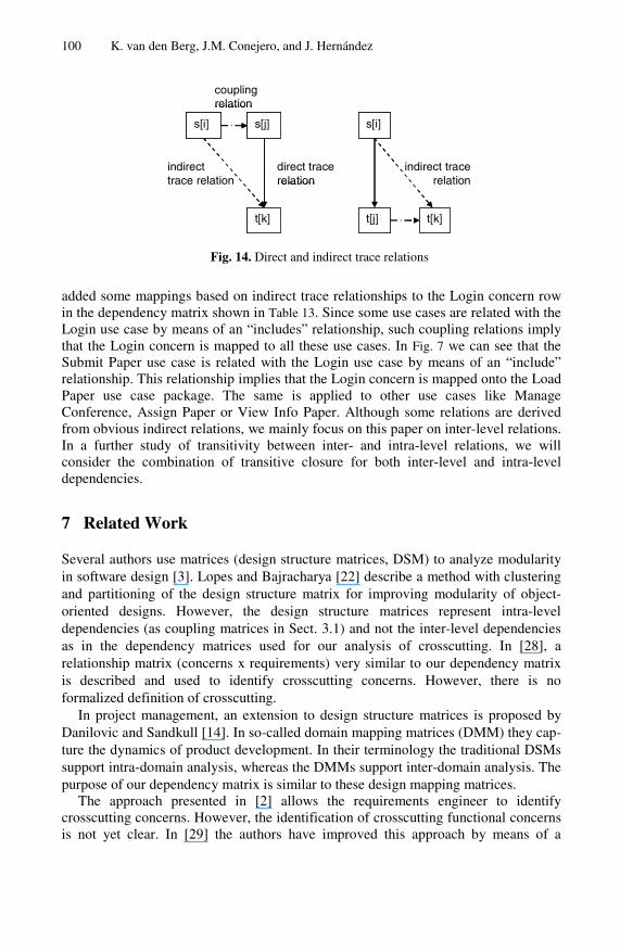
Intra-level trace dependencies combined with inter-level trace dependencies may cause dependencies, which we call an indirect trace dependency based on a pseudo-transitivity which can be described as follows. Assume source element s[i] has a coupling relation R' with source element s[j] (see Fig. 14). Moreover, source element s[j] has a dependency relation R with target element t[k]. Then the indirect dependency relation is ( s[i] R' s[j] ) ∧ ( s[j] R t[k] ) ⇒ ( s[i] R' R t[k] ). In the same way, assume source element s[i] has a dependency relation R with target element t[j] and target element t[j] is coupled with target element t[k] by means of R'. In that case the indirect dependency relation is ( s[i] R t[j] ) ∧ ( t[j] R' t[k] ) ⇒ ( s[i] R R' t[k] ).
One should clearly distinguish the direct (inter-level) dependency relation from this indirect dependency relation. Once we have identified all the direct dependencies, we must consider the possible indirect dependency relationships emerged from coupling relations. Intuitively, we are considering such relationships in the different case studies we showed in Sect. 5. For instance, in the CRS example in Sect. 5.4, we
100 K. van den Berg, J.M. Conejero, and J. Hernández
indirect trace relation
s[i]
t[k]
s[j]
t[k]t[j]
s[i]
couplingrelation
direct trace relation
indirecttrace relation
indirect trace relation
s[i]
t[k]
s[j]
t[k]t[j]
s[i]
couplingrelation
direct trace relation
indirecttrace relation
Fig. 14. Direct and indirect trace relations
added some mappings based on indirect trace relationships to the Login concern row in the dependency matrix shown in Table 13. Since some use cases are related with the Login use case by means of an “includes” relationship, such coupling relations imply that the Login concern is mapped to all these use cases. In Fig. 7 we can see that the Submit Paper use case is related with the Login use case by means of an “include” relationship. This relationship implies that the Login concern is mapped onto the Load Paper use case package. The same is applied to other use cases like Manage Conference, Assign Paper or View Info Paper. Although some relations are derived from obvious indirect relations, we mainly focus on this paper on inter-level relations. In a further study of transitivity between inter- and intra-level relations, we will consider the combination of transitive closure for both inter-level and intra-level dependencies.
7 Related Work
Several authors use matrices (design structure matrices, DSM) to analyze modularity in software design [3]. Lopes and Bajracharya [22] describe a method with clustering and partitioning of the design structure matrix for improving modularity of object-oriented designs. However, the design structure matrices represent intra-level dependencies (as coupling matrices in Sect. 3.1) and not the inter-level dependencies as in the dependency matrices used for our analysis of crosscutting. In [28], a relationship matrix (concerns x requirements) very similar to our dependency matrix is described and used to identify crosscutting concerns. However, there is no formalized definition of crosscutting.
In project management, an extension to design structure matrices is proposed by Danilovic and Sandkull [14]. In so-called domain mapping matrices (DMM) they cap-ture the dynamics of product development. In their terminology the traditional DSMs support intra-domain analysis, whereas the DMMs support inter-domain analysis. The purpose of our dependency matrix is similar to these design mapping matrices.
The approach presented in [2] allows the requirements engineer to identify crosscutting concerns. However, the identification of crosscutting functional concerns is not yet clear. In [29] the authors have improved this approach by means of a
Analysis of Crosscutting in Early Software Development Phases Based on Traceability 101
mechanism based on a natural language processor to identify functional and non-functional crosscutting concerns from requirements documents. However, this approach is focused only on requirements phases, while our approach can be applied throughout the software life cycle.
The papers described above lack the application of their identification of crosscutting to consecutive levels. We used our formalization to trace crosscutting concerns across levels of a software development process, as shown by the cascading operation.
A definition of crosscutting similar to ours can be found in [23] and [25]. Our definition is less restrictive as explained in [8]. Moreover, our definition can be applied to consecutive levels of abstractions in software development, such as requirements, design and implementation. This can be achieved through the cascading of dependency matrices as shown in Sect. 4.
Knethen and Paech [19] present a survey about tracing approaches. In this survey, the authors sum up the main relationships which can be used in order to trace elements in software engineering. They also explain the different entities we should consider to be traced and the tools used to represent such trace relationships. The authors establish three kinds of relationships: between documentation entities on the same abstraction, between documentation entities at different abstractions and between documentation entities of different versions of a software product. According to this taxonomy of relationships, we can classify our mappings between source and target within the second kind of relationships (between different abstractions). For instance, the two different abstractions could refer to concerns and representation of concerns in a particular phase (as we stated in Sect. 2.1). However, these different abstractions could also refer to refinements within a same level. For instance, we can consider trace dependencies in requirements between textual requirements and use cases.
Finally, there are several tools to show or represent the mappings between entities. In [32] we find tools based on traceability matrices, graphical models and cross references. We have used traceability matrices to show the mappings. By means of an extension to such matrices we are able to represent both the mappings between source and target elements and scattering and tangling in the system.
8 Conclusions
We proposed a definition of crosscutting based on an extension to traceability matrices, formalized in a crosscutting pattern. In a dependency matrix, we show the mappings between source and target. As an extension, we used this matrix to derive a crosscutting matrix and to identify crosscutting. This can be applied to any phases or abstraction levels in a software development process, including early phases. In [10] we applied the framework to modeling phases. The approach can be applied to systems where well known crosscutting concerns exist, but also in systems where crosscutting concerns should be identified. Obviously, the earlier we identify crosscutting in system development, the easier it is to cope with crosscutting in order to improve the quality of the system. Important properties of software such as
102 K. van den Berg, J.M. Conejero, and J. Hernández
modularity, reusability, evolvability or adaptability can be enhanced by means of an early identification of crosscutting.
An interesting application of our framework is the analysis of crosscutting across several levels in software development, for example from concern modeling to requirements, or from architectural design to detailed design and implementation. This analysis is formalized by means of cascading the crosscutting pattern. As such, it provides an approach for traceability analysis. We showed the application of the approach to some case studies to identify crosscutting. The operationalization of crosscutting with matrices constitutes a helpful means to analyze crosscutting in different scenarios or domains.
Other applications of our framework have been studied. Since evolvability in systems can be influenced by crosscutting, change impact analysis of crosscutting has been carried out in [7]. The framework has been applied to analyze the impact of crosscutting on MDA model transformations [11]. On the other hand, the framework may help developers not only to identify crosscutting but also to assess the degree of crosscutting in a system. In that sense, the crosscutting product matrix described in Sect. 3.2 provides important information for this purpose. We are investigating the definition of crosscutting metrics based on the crosscutting product matrices. Further research should show the scalability of this approach and provide support for different types of trace relations.
Acknowledgment. This work has been carried out in conjunction with the AOSD-Europe Project IST-2-004349-NoE (see [1]) and also partially supported by MEC under contract TIN2005-09405-C02-02. We would like to thank Ana Moreira for her comments and suggestions. We would also like to thank the anonymous reviewers who provided constructive comments and suggestions to enhance this work.
References
1. AOSD-Europe. AOSD Ontology 1.0 – Public Ontology of Aspect-Orientation (Retrieved May, 2005) (2005), from http://www.aosd-europe.net/documents/d9Ont.pdf
2. Araujo, J., Moreira, A., Brito, I., Rashid, A.: Aspect-Oriented Requirements with UML. In: Workshop on Aspect-Oriented Modelling with UML at International Conference on Unified Modelling Language. Dresden, Germany (2002)
3. Baldwin, C.Y., Clark, K.B.: Design Rules, The Power of Modularity, vol. 1. MIT Press, Cambridge (2000)
4. Baniassad, E., Clarke, S.: Theme: An Approach for Aspect-Oriented Analysis and Design. In: 26th International Conference on Software Engineering, pp. 158–167. Edinburgh, Scotland (2004)
5. Baniassad, E., Clarke, S.: Aspect-Oriented Analysis and Design: The Theme Approach. Addison-Wesley, Reading (2005)
6. Baniassad, E., Clements, P., Araújo, P., Moreira, A., Rashid, A., Tekinerdogan, B.: Discovering early aspects. In IEEE Software 23(1), 61–70 (2006)
7. van den Berg, K.: Change Impact Analysis of Crosscutting in Software Architectural Design. In: Workshop on Architecture-Centric Evolution at 20th ECOOP, Nantes (2006)
Analysis of Crosscutting in Early Software Development Phases Based on Traceability 103
8. van den Berg, K., Conejero, J.M.: A Conceptual Formalization of Crosscutting in AOSD. In: In Iberian Workshop on Aspect Oriented Software Development, TR-24/05 University of Extremadura, Granada, Spain, pp. 46–52 (2005)
9. van den Berg, K., Conejero, J.M.: Disentangling crosscutting in AOSD: A conceptual framework. Paper presented at the EIWAS2005, Brussels (2005b)
10. van den Berg, K., Conejero, J.M., Hernández, J.: Identification of crosscutting in software design. In: Aspect-Oriented Modeling Workshop at 5th AOSD, Bonn (2006b)
11. van den Berg, K., Tekinerdogan, B., Nguyen H.: Analysis of Crosscutting in Model Transformations. In: Aagedal, J., Neple, T., Oldevik, N.J. (eds) ECMDA-TW Traceability Workshop Proceedings 2006. SINTEF Report A219, pp. 51–64 (2006)
12. Bushmann, F., Meunier, R., Rohnert, H., Sommerlad, P., Stal, M.: Pattern-Oriented Software Architecture: A System of Patterns. Wiley, Chichester, UK (1996)
13. Cachero, C., Gómez, J., Párraga, A., Pastor, O.: Conference Review System: A Case of Study. In: [17] (2001)
14. Danilovic, M., Sandkull, B.: The use of dependence structure matrix and domain mapping matrix in managing uncertainty in multiple project situations. International Journal of Project Management 23(3), 193–203 (2005)
15. Davis, A.: Software Requirements: Objects, Functions and States, 2nd edn. Prentice-Hall, Englewood Cliffs (1993)
16. Finkelstein, A., Sommerville, I.: The Viewpoints FAQ. BCS/IEE Software Engineering Journal 11(1), 2–4 (1996)
17. In: First International Workshop on Web-Oriented Software Technology, Valencia, Spain (2001), http://www.dsic.upv.es/ west/iwwost01/
18. Gamma, E., Helm, R., Johnson, R., Vlissides, J.: Design patterns. Elements of reusable object-oriented software. Addison-Wesley, Reading (1995)
19. von Knethen, A., Paech, B.: A Survey on Tracing Approaches in Practice and Research. IESE-Report No. 095.01/E. v1.0. Fraunhofer Institut Experimentelles Software Engineering (2002)
20. Kiczales, G.: Crosscutting. AOSD.NET Glossary 2005 (2005), At http://aosd.net/wiki/ index.php?title=Crosscutting
21. Kiczales, G., Irwin, J., Lamping, J., Loingtier, M., Lopes, C.V., Maeda, C.: Aspect-Oriented Programming. In: Aksit, M., Matsuoka, S. (eds.) ECOOP 1997. LNCS, vol. 1241, pp. 220–242. Springer, Heidelberg (1997)
22. Lopes, C.V., Bajracharya, S.K.: An analysis of modularity in aspect oriented design. In: 4th International Conference on Aspect-Oriented Software Development. Chicago, Illinois (2005)
23. Masuhara, H., Kiczales, G.: Modeling Crosscutting in Aspect-Oriented Mechanisms. In: Cardelli, L. (ed.) ECOOP 2003. LNCS, vol. 2743, pp. 2–28. Springer, Heidelberg (2003)
24. MDA. MDA Guide Version 1.0.1, document number omg/2003-06-01 (2003) 25. Mezini, M., Ostermann, K.: Modules for Crosscutting Models. In: Rosen, J.-P.,
Strohmeier, A. (eds.) Ada-Europe 2003. LNCS, vol. 2655, pp. 24–44. Springer, Heidelberg (2003)
26. Moreira, A., Araujo, J., Whittle, J.: Modeling Volatile Concerns as Aspects. In: Dubois, E., Pohl, K. (eds.) CAiSE 2006. LNCS, vol. 4001, pp. 973–978. Springer, Heidelberg (2006)
27. Ramesh, B., Jarke, M.: Toward reference models for requirements traceability. IEEE Transactions on Software Engineering 27(4), 58–93 (2001)
28. Rashid, A., Moreira, A., Araujo, J.: Modularisation and Composition of Aspectual Requirements. In: Second Aspect Oriented Software Conference. Boston, USA (2003)

104 K. van den Berg, J.M. Conejero, and J. Hernández
29. Sampaio, A., Loughran, L., Rashid, A., Rayson, P.: Mining Aspects in Requirements. In: Early Aspects 2005 Workshop at Aspect Oriented Software Development Conference. Chicago, USA (2005)
30. Tekinerdogan, B.: ASAAM: Aspectual Software Architecture Analysis Method. In: 4th Working IEEE/IFIP Conference on Software Architecture (2004)
31. UML. Unified Modeling Language 2.0 Superstructure Specification. (Retrieved October, 2004) from (2004), http://www.omg.org/cgi-bin/doc?ptc/2004-10-02
32. Wieringa, R.J.: An introduction to requirements traceability. Technical Report IR-389, Faculty of Mathematics and Computer Science, Vrije Universiteit, Amsterdam (1995)
Related Documents


![Traceability for Sustainable Trade - UNECE · Traceability for Sustainable Trade] ECE/TRADE/429 2 . 1.2 The Purpose of the Traceability Framework . Current traceability systems are](https://static.cupdf.com/doc/110x72/5e8a3f92a86eb50a5f7cd6db/traceability-for-sustainable-trade-unece-traceability-for-sustainable-trade-ecetrade429.jpg)