Analysis of Crane and Lifting Accidents in North America from 2004 to 2010 by Ray Addison King B.S. Architectural Engineering The University of Texas at Austin, 2011 SUBMITTED TO THE DEPARTMENT OF CIVIL AND ENVIRONMENTAL ENGINEERING IN PARTIAL FULFILLMENT OF THE REQUIREMENTS FOR THE DEGREE OF MASTER OF ENGINEERING IN CIVIL AND ENVIRONMENTAL ENGINEERING AT THE MASSACHUSETTS INSTITUTE OF TECHNOLOGY JUNE 2012 @2012 Ray A. King. All rights reserved. The author hereby grants to MIT permission to reproduce and to distribute publicly paper and electronic copies of this thesis document in whole or in part in any medium now known or hereafter created. ARCHIVES Signature of Author: .4 1 Department of Civil and Certified by: Associate Professor of Building Technology and Civil and Accepted by: Environmental Engineering May 11, 2012 John A.3 &sendorf Environmental Engineering Iesis Sup rvisor Heidi 4. Nepf Chair, Departmental Committee for Graduate Students

Welcome message from author
This document is posted to help you gain knowledge. Please leave a comment to let me know what you think about it! Share it to your friends and learn new things together.
Transcript

Analysis of Crane and Lifting Accidents in North Americafrom 2004 to 2010
by
Ray Addison King
B.S. Architectural EngineeringThe University of Texas at Austin, 2011
SUBMITTED TO THE DEPARTMENT OF CIVIL AND ENVIRONMENTAL ENGINEERINGIN PARTIAL FULFILLMENT OF THE REQUIREMENTS FOR THE DEGREE OF
MASTER OF ENGINEERINGIN CIVIL AND ENVIRONMENTAL ENGINEERING
AT THE
MASSACHUSETTS INSTITUTE OF TECHNOLOGY
JUNE 2012
@2012 Ray A. King. All rights reserved.
The author hereby grants to MIT permission to reproduceand to distribute publicly paper and electronic
copies of this thesis document in whole or in partin any medium now known or hereafter created.
ARCHIVES
Signature of Author: .4 1
Department of Civil and
Certified by:
Associate Professor of Building Technology and Civil and
Accepted by:
Environmental EngineeringMay 11, 2012
John A.3 &sendorfEnvironmental Engineering
Iesis Sup rvisor
Heidi 4. NepfChair, Departmental Committee for Graduate Students

Analysis of Crane and Lifting Accidents in North Americafrom 2004 to 2010
by
Ray Addison King
Submitted to the Department of Civil and Environmental Engineeringon May 1 1 th, 2012 in Partial Fulfillment of the
Requirements for the Degree of Master of Engineering inCivil and Environmental Engineering
ABSTRACT
Cranes are the fundamental machinery used during lifting operations, and are crucial to the construction
industry. Several key construction processes would be impossible without cranes and the benefits they
provide. Cranes are often massive pieces of equipment capable of causing significant damage to both
property and human life. Because of their importance to the construction industry, and their potential
to cause harm, the safe and correct use of these machines is imperative. This study documents 75
recent accidents involving cranes in North America, systematically cataloguing them into detailed
categories. Comprehensive data sets have been compiled for each of the 75 incidents. Each data set
includes: the date and location of the incident, crane type and capacity, a review of the responsible
parties, conditions during the accident, causative factors, and the outcome of the accident. Cataloguing
of these incidents is based off of forensic engineering reports from licensed engineers who are well
established in the field, input from industry experts, photos, research of consensus industry safety
standards and regulations, and any other available documents. Upon being catalogued into a database,
these accidents have been statistically analyzed for patterns. Patterns in these crane accidents are then
used to identify areas where increased safety standards and regulations are needed. The study reviews
the importance of careful lift planning and offers data to be used to improve crane design, industry
safety standards, and lift coordination.
Thesis Supervisor: John A. Ochsendorf
Title: Associate Professor of Building Technology and Civil and Environmental Engineering


Acknowledgement
I owe my gratitude to a number of people for helping make the publication of this thesis possible.
First and foremost, I must give my appreciation to my family. They have made everything that I have
accomplished possible through their love and support. Thank you Rob, Susan, and Dana King.
I would like to thank my advisor, Professor John Ochsendorf, who has provided a tremendous amount of
support and guidance throughout my time at MIT.
Thank you to Professor Jerome Connor, who has been a leader to me throughout this program, as well
as an inspiring teacher.
I owe a tremendous amount of gratitude to Jim Wiethorn and Matthew Gardiner. Their years of hard
work and expertise provided the source material for this study. They were invaluable consultants for me
during the process of writing this thesis. Finally, their mentorship and encouragement over the years
has been more than I could have ever asked for.
I would also like to thank Tony Bond, John Wlascinski, Jason Clark, Ed Cox, and the rest of Haag
Engineering who have made this research possible through their extraordinary work during their
careers. I have learned a lot from them over the past four years.
Thank you to Dr. David Fowler of The University of Texas at Austin who was a great mentor to me
throughout my undergraduate education and provided me with the opportunity that led to my interest
in cranes.
Thank you to Professor Lawrence Speck of The University of Texas at Austin who encouraged me to
attend MIT and to work with Professor John Ochsendorf.
Finally I would like to thank my friends in the M.Eng program here at MIT who have been an amazing
support system and have provided me with great memories.
5

Table of Contents
Acknow ledgem ent........................................................................................................................................... 5
ListofTables................................................................................................................................................. 8
List of Figures ............. ................................................................................................................ 8
1. INTRODUCTION ..................................................................................................................................... 9
1.1 PROBLEM STATEM ENT.................................................................................................................... 10
2. LITERATURE REVIEW ... ............................................................................................................ 12
3. M ETHODOLOGY .............................................................................................................................. 15
3.1 GENERAL INFORM ATION S,.AN.S............ ........................................................................... 15
3.2 RESPONSIBLILITIES...................................................................................................................... 16
3.3 CONDITIONS, OUTCOM ES, AND CAUSATIONS ........................................................................... 17
3.4 DATA COM PILATION .................................................................................................................... 25
3.5 DATA SOURCESNS.B........................................................................................................................ 25
4. STUDY RESULTS ................................................................................................................................. 27
4.1 RESPONSIBILITIES........................................................................................................................ 27
4.2 CRANE TYPE OU OS.................................................................................................. 29
4.3 CRANE CAPACITY ......................................................................................................................... 31
4.4 CONDITIONS, OUTCOM ES, AND CAUSATIONS ..................................................................... 34
4.4.1 TYPE OF W ORK ................................................................................................................. 34
4.4.2 OPERATIONAL AIDS AND SAFETY DEVICES............................................................ ............. 35
4.4.3 PHYSICAL ISSUES ..... ............................................................................................................. 37
4.4.4 CRANE STABILITY ............................................................................................................. 39
4.4.5 LOAD............................................................................................................................... 41
4.4.6 CRANE OPERATION...... ........................................ .. ............................................. 42
4.4.7 RIGGING ............................................................................................................................ 42
4.4.8 CRANE TRAVEL...................... ................................................................. 44
4.4.9 W EATHER .......................................................................................... 44
4.4.10 LIFT PLANNING....................................................................................................................45
4.4.11 W RONG W EIGHT .................................................................................................................. 46
4.4.12 W ORKER CONTACT ............................................................................................................. 47
6

4.4.13 POW ER LINE CONTACT........................................................................................................48
5. DISCUSSIO N O F RESULTS .................................................................................................................... 49
6. CO NCLUSIO NS.....................................................................................................................................57
6.1 LIM ITATIO NS OF RESULTS...........................................................................................................58
6.2 AREAS O F FURTHER RESEARCH.............................................................................................. 59
REFERENCES................................................................................................................................................61
APPENDICES
Appendix A - Case Study Details................................................................................................................ 62
7

List of Tables
Table 4.1: Responsibilities...............................................................------------------------------------.......................27
Table 4.2: Responsibilities-Expanded Look .......................................... 28
Table 4.3: Crane Type ..............................................................----.. . -----------------------------............................. 30
Table 4.4: Crane Capacity Ranges ......................................................----. - ---.... 31
Table 4.5: Crane Capacity .................................................................------------ .. - ----------...................... 32
Table 4.6: W ork Site Type ....................................................................- - . -----------------------.................... 34
Table 4.7: Operational Aids & Safety Devices................................................................................. ... 36
Table 4.8: Physical Issues and Factors .............................................................................. 37
Table 4.9: Crane Stability Issues.........................................................................-----.. . ----------------............... 40
Table 4.10: Load Related issues ...................................................................-----------------------------................. 41
Table 4.11: Rigging Problem s.......................................................................-------------------------....................43
Table 4.12: W eather Issues...................................................................---- .... -- .. . --------------.................... 44
Table 4.13: Lift Planning..............................................................................------------------------------..................45
Table 4.14: W rong W eight ......................................................................---------------. ---------------.................... 46
Table 4.15: W orker Contact ............................................................................-- . . -----------------................ 47
Table 4 .16: Pow er Line Co ntact .............................................................................- -.----....--------------......... 48
List of Figures
Figure 1.1: Crane stability failure after crawler punches through a surface ............................................ 9
Figure 1.2: A tower crane collapses in Bellevue, W ashington ................................................................. 11
Figure 3.1: Zones of Responsibility ............................................................................. 16
Figure 4.1: Crane Type ............................................................................----------------------------...................... 31
Figure 4.2: Cranes Sorted by M axim um Rated Capacity........................................................................ 33
Figure 5.1: A collapsed lattice boom........................................................................ 52
Figure 5.2: Stability failure of a m obile lattice craw ler crane ................................................................. 53
Figure 5.3: Tilt-up w all falls on crane during erection ............................................................................ 54
8

1. INTRODUCTION
Cranes are the fundamental machinery used during lifting operations, and are crucial to the
construction industry. Several key construction processes would be impossible without cranes and the
benefits they provide. Cranes are often massive pieces of equipment capable of causing significant
damage to both property and human life. Because of their importance to the construction industry, and
their potential to cause harm, the safe and correct use of these machines is imperative. Figure 1.1
shows an example of what can happen if lift planning and execution are not carefully thought-out and
properly coordinated.
Crane accidents represent a
significant danger to workers and
bystanders alike. Safety standards have
been a continuous work in progress.
Recently organizations such as ASCE,
ASME, and OSHA have begun to produce
more detailed written guidelines for
crane and rigging safety. OSHA
organized a Cranes & Derrick Advisory
Committee (C-DAC) in July 2002 to assist
Figure 1.1: Crane stability failure after crawler punchesin updating OSHA 1926.550 to address through a surface. (Haag Engineering Co.)
the advancements in the crane industry, and to align with current ASME B30 committee requirements.
Their goal was to create a new set of regulations for cranes, OSHA 1926.1400, and also to support and
advance certification programs such as the National Commission for the Certification of Crane Operators
(NCCCO). On November 14, 2010, OSHA 1926.1400 became law, although its crane operator
9

certification requirement does not go into effect until November 14, 2014. Initial requirements for
"qualified" riggers and signal persons were also included in the original C-DAC document. While
certification is not yet a federal requirement, some localities such as Washington (State) require
documented qualifications and/or certifications for all personnel working with cranes.
A string of high profile crane accidents in 2008 increased public awareness of crane-related
hazards, and prompted Engineering News Record to devote its cover story to the topic of crane
collapses and inconsistent lifting practices and safety provisions. (Hampton 2008) Since then, crane
collapses have continued to occur frequently, but public interest has once again regressed towards
general apathy. However, the same risks associated with cranes that were present in 2008 remain in
place today.
Organizations such as NCCCO (National Commission for the Certification of Crane Operators)
have made strides towards providing affordable standardized rigger certification exams, but there
remains limited political movement towards requiring riggers to be certified.
1.1 PROBLEM STATEMENT
Each year, hundreds of costly accidents occur involving the use of one or more cranes. The
resulting financial and human cost of these accidents is great, and the delays they create can put added
pressure on schedule deadlines, exacerbating safety conditions on construction sites. Figure 1.2 (next
page) shows an example of the devastating effects a crane accident can have on the environment
around it. An increased understanding of the factors and trends in crane accidents is needed in order to
provide guidance for safety standards. Greater clarity on this subject would enable the continuation of
safer working conditions for those in the industries that use cranes and derricks. Currently, the
10

statistical analysis of crane accidents is still thin, and provides limited insight into the factors behind
crane accidents.
There is a need for a study that delves deeper into the causative factors of crane accidents.
Previous studies have used a limited list of factors. This study will significantly expand the number of
classification categories used to create statistical outputs. Additionally, patterns in crane type and lifting
capacity need to be analyzed. Finally, a study of the responsibilities of the parties involved in crane
accidents is a crucial step towards identifying the individuals who need the most instruction in crane
safety and their role in lifting operations.
Figure 1.2: A tower crane collapses in Bellevue, Washington.
(Haag Engineering Co.)
11

2. LITERATURE REVIEW
This study attempts to provide some statistical conclusions about the causes and details of
crane-related accidents. A number of previous studies have attempted to provide empirical conclusions
about crane-related incidents in the U.S. construction industry.
Beavers et al. (2006) provided a statistical review of crane related fatalities in 2006. The study's
source data covers the years 1997-2003, drawing from the United States Occupational Safety and Health
Administration's (OSHA) Integrated Management Information System (IMIS) using a series of search
keywords. The IMIS database provides summary reports about each of their catalogued incidents.
These summaries can be terse however, and to further support their data, the authors obtained each
chosen case study's full OSHA report file. By obtaining the full case files, the 2006 Beavers et al. study
was based on a more complete set of data than similar studies that preceded it.
Their ultimate goal was to provide a study "classifying recent fatal events by proximal cause,
contributing physical factor, project end use, construction operation, existence of an employer safety
and health program, OSHA citations, and various other factors." The authors have provided the most
comprehensive statistical data on this subject to this date. However, it should be noted that the basis
for this study relied on the investigative skills of OSHA personnel who had a focus on determining what
parts of the regulations were violated strictly in the employer-employee relationship. OSHA's
investigators do not have the technical expertise to determine the specific cause of many accidents.
Also, the OSHA reports typically address all observed violations that occurred during an accident,
whether those violations caused or contributed to the incident or not. Finally, OSHA only gets called to
an accident when there are multiple serious injuries, fatalities, a worker blows the whistle, or an OSHA
official is already on site.
12

Saruda et al. (1999) published a study that also drew from OSHA investigation records. Their
data was based upon the previously mentioned IMIS summary reports, and covered 502 deaths
occurring in the years of 1984-1994.
Shepard et al. (2000) completed a study very similar to Saruda et al., analyzing over 500 OSHA
crane fatality situations spanning the years 1985-1995.
Hinze and Bren (1996) analyzed OSHA reports, concluding that cranes were involved in a large
number (38%) of fatal electrocutions involving heavy equipment in the U.S. construction industry.
A 2009 paper by Shapira and Lyachin sought to identify and analyze the factors that contribute
to safety of a specific type of construction crane known as a tower crane. Their study relied on the input
of an expert panel, shunning statistical data. The authors note:
Statistics on construction accidents involving tower cranes could have been a
reliable source of information for this kind of study. In reality, however, statistics
suitable to serve the purposes of this current study hardly exist-for tower or
mobile cranes. First, crane accidents are commonly reported only in cases of
fatalities or severe injuries (Fair 1998). Therefore, numerous cases simply do not
make it into the statistics, even if they are reported within the construction
company. These cases, which may involve injuries or "only" cost damages,
constitute the majority of crane related accidents.
But even when statistics and accident records are at hand, they usually provide
information on the circumstances, nature, outcomes, symptoms, and even
proximal causes and contributing physicalfactors of accidents; only very rarely do
they go all the way in providing the root causes of the accident investigated
(Hdkkinen 1993; Hinze et al. 1998; Abdelhamid and Everett 2000; Neitzel et al.
2001; Beavers et al. 2006).
As Hammer (1989) stated: "Accident statistics . .. do not answer questions about
what causes accidents . . . They do not indicate relationships between causes and
effects." He adds that "even where accident and injury statistics can be useful,
they are often incomplete, inaccurate, and therefore incorrect."
13

Several of the flaws in statistical data on crane accidents noted by Shapira and Lyachin can be
found in the studies mentioned above. The previous studies suffer from all relying on the same data:
OSHA reports. OSHA does not cover workers in the public sector or those who are self-employed.
These reports are limited in their jurisdiction, detail, and most importantly, only include accidents that
result in fatalities or multiple injuries. These reports are also often inconsistent, having been compiled
from multiple sources using different reporting methods and terminology. Additionally, previous studies
have ignored accidents that did not result in a fatality.
This current study attempts to improve on previous studies by addressing their shortcomings.
The source data will be more complete, using engineering reports, photographs, videos, witness
depositions, company safety documents, and the inputs of several industry experts to arrive at its
conclusions. The categorization of crane accidents will be more comprehensive, attempting to draw
stronger relationships between cause and effect. While previous studies have focused primarily on
failure modes and proximal causes, this study will put an additional emphasis on identifying the human
parties responsible for the incident. Another significant difference between this study and previous
statistical analyses is that this study analyzes crane-related accidents of all types of loses - from fatalities
to incidents only resulting in loss of property and/or delays in schedule. The cases are also more recent
than those utilized in previous studies, allowing for conclusions that are up-to-date and relevant to the
industry in its current state.
14

3. METHODOLOGY
A collection of case files involving crane-related incidents was reviewed, and a sample of 75
cases was selected. The selected incidents occurred in 27 U.S. states with one occurring in Mexico.
These case files contained detailed engineering analysis of crane-related accidents, ranging from minor
property damage to multiple fatalities and massive property loss. The case files were obtained from
Haag Engineering Co. These forensic engineering reports were completed by the same team of licensed
professional engineers, using a consistent methodology for each case.
From these engineering reports, the author compiled a "data profile" for each individual case.
As a selection method, the 75 most recent (by date of incident) complete data profiles were chosen. A
summarized data profile for all 75 case studies can be found in Appendix A.
3.1 GENERAL INFORMATION
Each case file was given a number and noted with the following general information:
e Date of Incident
e Location of Incident
e Type of Crane (Manufacturer, Classification, Model, Capacity)
e Any Pertinent Crane Attachments Present
* Any Pertinent Alterations or Modifications
The general information has allowed the author to analyze trends in crane type and lifting capacity.
15

3.2 RESPONSIBLILITIES
The case files were then analyzed for responsible parties/entities. The following categories
were addressed:
e Site Supervisor
e Lift Director
e Rigger
e Operator
* Service Provider
" Owner/User
" Signal Person
* Manufacturer
e Other
* ~Dedi ~ en
fsFp
Figure 3.1: Zones of Responsibility (ASCE No. 93)
The allocation of responsibilities for crane safety is outlined in the ASCE (American Society of Civil
Engineers) Manuals and Reports on Engineering Practice No. 93, Crane Safety on Construction Sites.
Figure 3.1 (ASCE No. 93) shows a visual representation of the zones of responsibility for each party. The
engineering reports used the ASCE No. 93 report and subsequent ASME B30.5-2007 standard to allocate
responsibility to the involved parties. It is understood that the ASCE No. 93 standards describe
responsibilities for crane operations on construction sites that have been defined as far back as the early
1980's. (Dickie 1982) The ASME (American Society of Mechanical Engineers) B30.5: Mobile and
Locomotive Cranes is based off of these same early standards.
16

Care was taken to determine if an engineer believed that a certain party was either a primarily
responsible party to the accident or simply secondarily. A primarily responsible party has been defined
as a party who failed in their responsibility in such a way that, without their breach of responsibility, the
accident would not have occurred. A secondarily responsible party has been defined as a party whose
breach of responsibility exacerbated the accident, but it would have occurred regardless due to other
factors. The responsible parties were then catalogued as such, either "primary" or "secondary". It
should be noted that multiple parties can be considered primarily responsible. Multiple parties can also
be considered secondarily responsible. It is also possible that one entity may be filling the role of
multiple parties. For example, the crane operator may also be acting as the lift director under certain
conditions.
3.3 CONDITIONS, OUTCOMES, AND CAUSATIONS
A broad list of accident classification categories was created using the cumulative input of a
range of subject matter experts. A glossary of crane and rigging terms was also consulted in the creation
of this list. (SC&R 1997) The list attempts to provide a blanket of potential conditions during the
accident, physical outcomes, and causations of the accident. These classifications are not mutually
exclusive. Cases were'checked for every category, and the categories that were present during each
accident were identified. Definitions for accident classification terms are listed below:
Operational Aid -- Accessories that provide information to facilitate operation of a crane or that takescontrol of particular functions without action of the operator when a limiting condition is sensed.
Operational aid override -- The operator performed some type of action to circumvent the device.(Inserting a "penny" has been a typical LMI override maneuver.)
Operational aid improper set up -- The operator did not input the necessary or correctinformation/configuration into the system, resulting in incorrect output.
Operational aid not used -- The device was never turned on.
17

Operational aid not present -- The device was not installed on the crane.
Operational aid malfunction -- A portion or function of the aid was not registering. Errors or glitches
occur when device is properly set up. The device does not function altogether.
Safety Devices -- Accessories designed to limit unsafe operation.
Safety device override -- The operator performed some type of action to circumvent the device.
Safety device not used -- The device was never turned on.
Safety device not present -- The device was not installed on the crane.
Safety device malfunction -- A portion or function of the aid was not registering. Errors or glitches occur
when device is properly set up. The device does not function altogether.
Physical Issue -- A physical component of the crane contributed to the accident.
Manufacturing Issue -- An issue present before crane is ever operated in the field.
Manufacturing design -- A design flaw in the crane or one of its components.
Fabrication/Manufacturer Assembly -- Faulty component or initial assembly error. Includes
substandard welds.
Structural Issue -- A structural failure of the boom or other component when it has not been
overloaded.
Fatigue -- Fatigue failure of material.
Corrosion Structural Issue -- Corrosion of metal component(s).
Aging -- General deterioration of structural components not attributable to any acute cause.
Mis-Use -- Physical mis-use that was not in conformance with standard operating procedures.
Overload Physical Issue -- The crane experienced structural failure due to excessive weight.
Physical Abuse -- The crane experienced structural failure due to abuse such as shock loading or impact
from objects/equipment.
Damage From Previous Use -- Pre-existing damage contributed to the mechanical/structural failure of
the crane.
Broken Chords - Chords were previously broken, deformed, or degraded.
Deflected Boom - Boom was previously plastically deformed.
18

Broken Connection - A connection was broken before operation.
Mechanical Failure of Component -- Component failure not attributed to a manufacturing issue.
Hydraulic Cylinder - A hydraulic cylinder failed.
Brakes - The brake system on the crane failed.
Outriggers - The outriggers failed.
Electrical System - The electrical system failed.
Engine - The crane engine failed.
Wire Rope - A physical failure of the wire rope.
Load Line - The load line wire rope experienced a physical failure.
Hoist Line - The boom hoist line wire rope experienced a physical failure.
Line Shock Load -- Wire rope is compromised from shock loading. Includes fractured rope andbirdnesting.
Line Corrosion -- Wire rope is used that has been compromised by corrosion.
Line Crushing- Wire rope has been crushed. May be caused by crane drum or other physical abuse.
Line Excessive Wear -- Wire rope has been compromised by excessive wear.
Wrong Wire Rope for the Application -- The incorrect wire rope was used.
Other Physical Issue - Any other pertinent mechanical/physical problem.
Crane Stability -- The crane loses stability.
Soil (Mobile Crane Stability) -- The underlying soil contributed to the loss of stability.
Loose Soil -- Soil was not sufficiently compacted, leading to crane movement.
Prior Trench Excavation -- Previous earthwork destabilized crane set-up area.
Outrigger Instability -- Stability issue due to outrigger set-up.
Improper Cribbing or Mats -- Inadequate cribbing or mats are used or they are improperly set-up.
Outrigger Punches through Hard Surface -- Outrigger punches through surface such as a mat orpavement.
19

Outriggers Not Extended -- Outriggers are only partially extended during lift or not extended at all.
Outriggers Not Level -- The crane is not level due to improper use of outriggers.
Foundation (Tower Crane Stability) -- The tower crane foundation contributes to the loss of stability.
Tie Ins (Tower Crane Stability) -- The lack of use or the improper installation or design of tower crane
tie-ins leads to instability.
Absence of Brace -- No brace is installed where one is needed.
Installation Error -- Brace is not installed correctly, leading to reduced stability.
Operator Set-Up -- Crane is not safely positioned or configured for a lift.
Level -- Crane in not level.
Ground Contact -- Crawlers not extended, tires do not clear ground, one (or more) outriggers do not
contract ground, etc.
Overload Stability -- The crane loses stability due to excessive weight.
Wrong Counterweights -- The wrong counterweight configuration is used, leading to a loss of stability.
Load Miscalculated -- The magnitude of the load is miscalculated.
Load Chart Misread -- The operator misreads the load chart or enters the incorrect data into the LMI.
Operator Error -- The operator performs a maneuver that takes the crane from within capacity to over
capacity.
Lost Load -- The crane loses stability due to the sudden loss of a load.
Floating Foundation/Surface -- The floating surface becomes unstable/moves causing instability of the
crane.
Load -- A load that did not exceed the capacity of the crane, but which ultimately caused an accident.
Placement -- Placing a load on framing or other platform that could not support the load.
Load Stability -- The load shifts or is swung such that it causes instability of the crane.
Load Falls Apart -- The load is too fragile, unstable, or not properly bundled. The load may lack the
necessary brackets or connection plates.
Crane Operation -- Improper operations of the crane by the operator.
20

Stuck Load -- The operator pulled on a stuck load that overloaded the crane, or buckled the boom, oroverturned the crane, or caused some type of dynamic loading when released.
Manual Violation -- The operator set up or operated the crane in a manner that was in direct violationof the operator's manual.
Inadvertent Operator Movement -- The operator moved/pulled the wrong lever.
Excessive Speeds -- The operator created dynamic loading by moving or swinging the crane too fast.
Maintenance -- The lack of maintenance which was a contributing factor to the accident.
Inspection/Certification -- Inspection/certification records are an issue. The inspector failed to properlyinspect the crane in accordance with national standards.
Expired/Non-Existent -- Inspection records are expired or missing. Inspection did not occur.
Inspection Errors -- Crane with issue(s) passes inspection. A missed item (issue) contributes to theaccident.
Corrosion Maintenance -- Corrosion left unchecked, resulting in decreased performance.
Mechanical Parts Maintenance -- Crane components neglected, resulting in decreased performance.
Structural Integrity Maintenance -- Displaced, bent, or broken members not repaired.
Critical Lift -- Critical lift planning was flawed. "Any lift utilizing multiple cranes is always a critical lift.Other criteria would be the weight of the equipment to be lifted as compared to the allowable lift, theswing area of the lift, the overall risk, difficulty, or complexity of the lift, toxicity of the product beinglifted, and other considerations at the discretion of the producer of the lift plan." (ASCE)
Lift Planning -- Factors and decisions leading up to, and during, the lift.
Site Controls -- The controlling contractor interfered with ingress or egress; some site issue that was notin control of the operator.
Wrong Weight Planning -- The lift director provided the wrong weight.
Plan Issues -- The lift plan had one or more errors and/or omissions which caused or contributed to theaccident.
Conditions Changed From Plans -- A site condition varied from what was originally planned for.
Rigging -- The type and/or configuration of the rigging that secures the load and attaches to the hookcauses or contributes to the accident.
Rigging Failure -- Some part of the rigging physically failed during the lift.
21

No Softeners -- Rigging failed due to being cut by a sharp edge due to the lack of softeners.
Tag Lines -- Tag lines, or the lack thereof, led to the loss of control of the load.
No Tag Line -- Tag line not used.
Tag Line Tangles -- Tag line tangles on an object or person, causing the load to shift or the person to be
dragged.
Not Balanced -- The load becomes unbalanced at some point during the lift.
CG is Unknown - The load center of gravity is unknown, leading to a rigging failure.
Rigging Not Secured - The rigging was not secured, leading to an unbalanced load.
Wrong Type of Rigging Used -- Some combination of rigging components led to failure.
Crane Travel -- Traveling the crane while not performing a lift or traveling in a partially erected or
configured manner.
Off Site Travel -- Travel while not on a job site.
On Site Travel -- Traveling while on a job site.
Road Travel -- Accident occurred while traveling on a road.
Bridge Impact -- Crane impacts a bridge or tunnel while traveling or being transported.
Tip Over -- Crane tips while traveling.
Improper Boom Securement -- Boom not secured causing it to fall off or be otherwise damaged.
Upper Crane Not Locked - House lock not engaged. Upper crane swings, causing crane to tip.
Outriggers Not Set Up For Travel -- Outriggers are not extended just above grade.
Unauthorized Operator -- Rigger or non-operator personnel moves the crane.
Engineering Issues -- An engineer involved in the lift plan design performs an improper design. Also
includes support condition design (tower crane foundation/tie-ins).
Wind -- Wind contributes to the accident.
Ice -- Ice contributes to the accident.
Fog -- Fog contributes to the accident.
Lightning -- Lightning contributes to the accident.
22

Boom Impact -- The boom comes into contact with a stationary object, causing it to collapse or drop itsload.
Operator Caused Boom Impact -- The operator swings into a stationary object that is in clear view.
Spotter Caused Boom Impact -- A designated spotter used to ensure proper clearance does not do hisjob and the boom contacts a stationary object.
Blind Pick Signal Issues -- Either hand, hard-wired, or wireless communications cause or contribute tothe accident. The operator has no visibility of the load for all or a portion of the lift. He relied on badsignals.
Assembly -- An accident occurred during or because of the erection of the crane.
Assembly in Accordance -- Erection was in accordance with the manufacturer's specifications.
Assembly Not in Accordance -- Erection was not in accordance with the manufacturer's specifications.
Disassembly -- An accident occurred during or because of the dismantling of the crane.
Disassembly In Accordance -- Dismantling was in accordance with the manufacturer's specifications.
Disassembly Not in Accordance -- Dismantling was not in accordance with the manufacturer'sspecifications.
Change of Configuration -- An accident occurred during or because of the changing of the configurationof the crane.
Jumping a Tower Crane - An accident occurs while jumping a tower crane.
Erecting a Jib - An accident occurs while erecting a jib.
Attaching a Man Basket - An accident occurs while attaching a man basket.
Change of Wire Rope -- Accident occurred during or because of the changing of wire rope.
Worker Contact -- A worker is struck by the load, crane, or parts of either that fall as a result of anaccident.
Load Falls -- The load either comes free during a lift or falls due to crane failure/collapse. Employee islocated in the fall zone.
Hit By Part of Crane -- Any part of the crane, either during normal operations or as a result of anaccident, strikes a worker/bystander.
Load Drifts -- Load is lifted and drifts from its original location. Common to pin a worker against astationary object.
23

Snagged By Rope -- A worker becomes entangled in a wire rope. May result in becoming trapped in a
winch.
Wrong Weight -- In some manner, the load being lifted is greater than previously determined.
Wrong Weight Provided -- The weight of a load is provided by an outside source that is incorrect.
Operator Wrong Weight -- The operator either does not ask how much the load weighs, or performs an
incorrect calculation.
Demolition -- The cubic foot estimate is incorrect.
Power Line Contact -- Part of the crane or load comes in contact with electric power lines.
Operator Caused Power Line Contact -- The operator swings into a power line.
Boom Contacts Power Line -- The boom contacts the power line.
Load Line Contacts Power Line -- The load or the load line contacts the power line.
Rigger Caused Power Line Contact -- Rigger pulls the load or the load line into the power line. Rigger
contacts energized crane or line.
Site Supervisor Power Line Contact -- Controlling contractor does not appropriately identify or abate
the hazard prior to the use of cranes.
Radio Wave -- Radio wave interference or electrical charge from wireless tower.
Crane Safety -- Training and planning to anticipate dangers and educate workers.
No Crane Safety Plan -- Employees not educated on general crane safety.
No Crane Lift Plan -- No lift plan is made.
No Critical Lift Plan -- No lift plan is made for a critical lift.
Heat/Hazmat -- Failure to consider the effects of heat or hazardous material.
Commercial -- Commercial Construction
Industrial -- Industrial, Manufacturing, or Refineries
Highway -- Road, Bridge, or Highway Construction
Residential -- Residential Construction
Marine -- Port, Barge, Off-shore
24

Of these categories, some are considered sub-categories of others. Every category is first
analyzed as a percentage of all 75 cases. For example "corrosion maintenance" (as defined above) was
identified in 3 out of 75 cases, or 4% of all cases. However, further analysis shows that "maintenance
problem" was identified in 11 out of 75 cases (14.7%). "Corrosion maintenance" is considered (by the
author) a subcategory of "maintenance problem," and therefore, "corrosion maintenance" was
identified in 3 of the 11 cases with a "maintenance problem," or 27.3%. This provided the author with
the ability to draw conclusions based off of the information that maintenance problems were present in
14.7% of cases, and that corrosion maintenance problems accounted for 27.3% of those maintenance
problems.
3.4 DATA COMPILATION
A case file that included the general information, the party responsibility information, and the
conditions, outcomes, causation category information was considered a complete data set.
Microsoft Access was utilized to compile the 75 data sets. From the compiled database, various
statistical tables have been generated using Microsoft Excel, providing insight about trends in these
crane-related accidents.
3.5 DATA SOURCES
Data was collected from accident files compiled at Haag Engineering Co. The authors/compilers
of these files are licensed professional engineers with extensive knowledge and expertise in the crane
and construction industries; as well as members on national consensus organizations of standards
(ASME B30) and certification (NCCCO). They followed the same methodologies for every case file that
they compiled and analyzed. These files range in size and detail, but typically contain engineering
reports carefully documenting the incident, photographs, depositions, crane manufacturer information,
25

and safety documents. Additional relevant documents and media are included in the files on a case-by-
case basis. Only cases that had sufficient detail to create complete, consistent data profiles were used
in this study. The source data files cover crane-related accidents from 1986 through 2010, however,
only the 75 most recent cases were used for this study (October 2004 to October 2010).
A number of industry subject matter experts were consulted to help create the list of causation,
condition, and outcome categories to be used in classifying the individual crane cases.
26

4. STUDY RESULTS
The results of this study are reviewed below:
4.1 RESPONSIBILITIES
Table 4.1 shows the number of times (count) that each party breached their responsibility for
the crane lift. The responsible parties can be observed in Table 4.1 in descending order of frequency.
Table 4.1 does not take into consideration whether the party was considered "primarily" or
"secondarily" responsible. It should be noted that the responsible parties are not mutually exclusive
(often multiple parties did not fulfill their responsibility), and therefore, the count does not total 75.
Table 4.1: Responsibilities
Party Count (out of 75) Percentage
Operator
Lift Director
Site Supervisor
Rigger
Owner/User
Signal Person
Manufacturer
Other
Service Provider
32
29
22
21
10
9
6
6
4
42.7%
38.7%
29.3%
28.0%
13.3%
12.0%
8.0%
8.0%
5.3%
The table shows that the operator failed in his responsibility to some extent in 32 out of the 75
cases studied, or 42.7%. The operator was the most frequently responsible party, followed closely by
the lift director. The site supervisor and rigger were the next two most frequently cited parties.
27

Rounding out the parties were the owner/user, signal person, manufacturer, other, and service
provider.
Table 4.2 gives an expanded look at the responsible parties by distinguishing between times
when a party was determined at "primarily" or "secondarily" responsible. Again, the responsible parties
were not mutually exclusive, and the total count will not sum to 75.
Table 4.2: ResDonsibilities-Expanded Look
Party Count (out of 75) Percentage of All Cases Percentage of Category
Site Supervisor 22 29.3% -
Site Supervisor Primary 16 21.3% 72.7%
Site Supervisor Secondary 6 8.0% 27.3%
Lift Director 29 38.7% -
Lift Director Primary 23 30.7% 79.3%
Lift Director Secondary 6 8.0% 20.7%
Rigger 21 28.0% -
Rigger Primary 19 25.3% 90.5%
Rigger Secondary 2 2.7% 9.5%
Operator 32 42.7% -
Operator Primary 24 32.0% 75.0%
Operator Secondary 8 10.7% 25.0%
Service Provider 4 5.3% -
Service Provider Primary 3 4.0% 75.0%
Service Provider 1 1.3% 25.0%Secondary
Owner/User 10 13.3% -
Owner/User Primary 8 10.7% 80.0%
Owner/User Secondary 2 2.7% 20.0%
Signal Person 9 12.0% -
Signal Person Primary 6 8.0% 66.7%
Signal Person Secondary 3 4.0% 33.3%
Manufacturer 6 8.0% -
Manufacturer Primary 3 4.0% 50.0%
Manufacturer Secondary 3 4.0% 50.0%
Other 6 8.0%
Other Primary 5 6.7% 83.3%
Other Secondary 1 1.3% 16.7%
28

Table 4.2 provides insight into the typical relative importance of each party's breach of
responsibility. For example, when looking solely at primarily responsible parties, the crane operator is
now only implicated in 32% of the 75 accidents. The lift director is primarily responsible for 30.7% of the
75 accidents. The comparison of 32% versus 30.7% represents a smaller difference between the two
parties than when "primary" and "secondary" were lumped.
The "Percentage of Category" column of Table 4.2 allows for some analysis of the weighted
importance of each party's lapse of responsibility. The manufacturer had a 50% primary to 50%
secondary distribution of their breach of responsibilities (a 1-to-1 ratio). This 1-to-1 ratio was the lowest
among the parties, implying that when the manufacturer does err, the consequences are less frequently
catastrophic. The highest percentage of primary breaches was the rigger (90.5%). The rigger's 19-to-2
ratio implies that even though they are not the most frequently responsible party, when they do err, the
result is usually disastrous.
4.2 CRANE TYPE
The type of crane involved in each accident was recorded. Table 4.3 displays the type of cranes
found in this study, descending from most frequent to least frequent. Figure 4.1 provides a graphical
representation of Table 4.3. The most commonly involved crane was the lattice crawler crane type that
was involved in 18 of the 75 case studies (24%). Cranes that have wheels or crawlers represented 69%
of all the cranes involved in accidents. The most common non-mobile crane was the tower crane, which
was involved in 12 of 75 cases (16%).
29

Crane Type
Lattice Crawler
Hydraulic Truck
Tower
Lattice Rubber Tire
Overhead Crane
All Terrain
Rough Terrain
Pedestal
Custom
Telehandler
Custom Mega Crane
Gantry
Log Boom Crane
Stiffleg Derrick
Side Boom Pipelayer
Gin Pole Truck
Truck Mounted Boom
Mounted Marine Dredger
Table 4.3: Crane Type
Count (out of 75)
18
14
12
6
5
4
3
3
1
1
1
1
1
1
1
1
1
1
30
Percentage
24.0%
18.7%
16.0%
8.0%
6.7%
5.3%
4.0%
4.0%
1.3%
1.3%
1.3%
1.3%
1.3%
1.3%
1.3%
1.3%
1.3%
1.3%

Figure 4.1: Crane Type
4.3 CRANE CAPACITY
The maximum rated capacity of each crane
involved in the case studies was documented. The
maximum rated capacity represents the highest load
that is allowed when the crane is at its ideal
configuration. These rated capacities have a safety
factor built-in. There were four case studies in which
information on the crane capacity was unavailable.
Capacity
1-25 Ton Total
30-75 Ton Total
80-230 Ton Total
250+ Ton Total
Unknown
31
Rough p(Terrain
4%
All Terrain5%
OverheadCrane
7%
Lattice Rubber Tire8%
Table 4.4: Crane Capacity Ranges
Count
19
18
19
15
4
Percentage
25.3%
24.0%
25.3%
20.0%
5.3%

Table 4.5: Crane Capacity
Crane Capacity
40 Ton
200 Ton
50 Ton
230 Ton
300 Ton
20 Ton
Unknown
25 Ton
250 Ton
5 Ton
8 Ton
30 Ton
75 Ton
80 Ton
150 Ton
600 Ton
1 Ton
Count
7
6
5
5
5
4
4
3
3
2
2
2
2
2
2
2
1
Percentage
9.3%
8.0%
6.7%
6.7%
6.7%
5.3%
5.3%
4.0%
4.0%
2.7%
2.7%
2.7%
2.7%
2.7%
2.7%
2.7%
1.3%
Crane Capacity
3 Ton
4.5 Ton
6 Ton
7 Ton
10 Ton
16 Ton
45 Ton
65 Ton
90 Ton
100 Ton
110 Ton
165 Ton
440 Ton
455 Ton
850 Ton
1100 Ton
2500 Ton
Table 4.4 displays the crane capacity ranges divided into roughly quartiles. Of note, a full
quarter of the studied accidents involved cranes that could lift no more than 25 tons. Table 4.5 shows
all of the involved cranes' capacities, listing them by most frequent to least. By tracking the maximum
rated capacity of the cranes in the case studies, the author was able to obtain a general estimate of the
32
Count
1
1
1
1
1
1
1
1
1
1
1
1
1
1
1
1
1
Percentage
1.3%
1.3%
1.3%
1.3%
1.3%
1.3%
1.3%
1.3%
1.3%
1.3%
1.3%
1.3%
1.3%
1.3%
1.3%
1.3%
1.3%

size of the lifting operation. Most cranes were not configured for a maximum rated load, and therefore
were lifting or expecting to lift a load less than the shown capacities. In fact, the largest crane in the
study, a 2,500 ton mega, or "super heavy-lift" crane, did not have a load on the line at the time of its
collapse.
Figure 4.2 is a bar graph plotting the number of cranes by their maximum rated capacity. The
bar graph provides a visual distribution from which clusters of crane capacities can be identified.
8
6
04
y~_ ...I.I. i_ . .I.. ....
Maximum Rated Capacity
Figure 4.2: Cranes Sorted by Maximum Rated Capacity
There are two noticeable clusters of cranes. Twenty-two of the seventy-five cranes were rated
within the range of 20 to 50 ton. Nineteen of the seventy-five cranes counted in the study were within
the range of 200 to 300 ton. The two clusters are notably different in relative lifting scale. The first
cluster appears to be the cranes commonly used in "lighter" lifting operations for general construction
use, while the second cluster represents the most commonly used cranes in "heavier" lifting operations.
33

4.4 CONDITIONS, OUTCOMES, AND CAUSATIONS
The conditions, outcomes, and causations portion of the data sets represented the largest and
most detailed area of information in this study. The primary categories will be reviewed below.
4.4.1 TYPE OF WORK
The "type of work" categories were intended to provide an insight into the nature of the work
sites where crane accidents are most common. Table 4.6 shows the five categories of work sites, and
provides the percentage of the 75 case studies they represented. Work sites being used for commercial
construction were the most common locations for crane accidents. Commercial construction sites were
the location of 46.7% of the case studies reviewed in this study. Industrial (industrial, manufacturing
plants, or refineries) work sites were the second most common location for crane-related incidents,
comprising 33.3% of the case studies. Marine (port, barge, off-shore) work sites were the location of
10.7% of the accidents, and highway and residential rounded out the locations with 6.7% and 2.7%
respectively.
Table 4.6: Work Site Type
Commercial 46.7%
Industrial 33.3%
Highway 6.7%
Residential 2.7%
Marine 10.7%
34

4.4.2 OPERATIONAL AIDS AND SAFETY DEVICES
Case studies were reviewed to determine whether the improper use or failure of an operational
aid or safety device contributed to the accident in question. The engineering reports directly identified
this problem in 12 out of 75 cases. Table 4.7 identifies the operational aids and safety devices in
question and details how they were deficient in the accident.
The most commonly cited device was the Load Moment Indicator (LMI) or equivalent device. In
seven of the case studies, the LMI was either overridden, improperly set-up, or not used. The most
common Safety Device cited was the Anti-Two Block Device (A2B) which prevents the operator from
pulling the load line all the way to the sheave on the tip of the boom, keeping the load block from
contacting the boom/sheave/upper block, which can create life-threatening forces in the hoist line. The
A2B device was overridden or defective in 3 of the 75 case studies. The Lattice Boom Hoist Disconnect
Device, or "boom kick out," was cited in one case study. The "boom kick out" sets a boom angle safety
limit such that the device disengages the boom hoist power source to prevent the boom from passing
the angle limit.
35

Table 4.7: Operational Aids & Safety Devices
Operational Aid & Safety Device
Operational Aid
12
Count
of 75
Percentage of All Cases*
16.0%
Percentage ofCategory*
Load Moment Indicator(LMI)
Boom Angle or Radius Indicator
Boom Length Indicator
Crane Level Indicator
Drum Rotation Indicator
Wind Speed Indicator
Other Operational Aid
1
1
0
CountSafety Device
9.3%
0.0%
0.0%
0.0%
0.0%
0.0%
1.3%
Operational Aid Override
Operational Aid improperSet Up
50.0%
37.5%
Operational Aid Not Used 12.5%
Operational Aid Not 12.5%Present
Malfunction 0.0%
Percentage of All Cases* Percentage ofCategory*
Anti-Two Block Device (A2B)
Lattice Boom Hoist Disconnect Device (BoomKick Out)
Proximity Warning Device
3
1
0
2
0
1
1
4.0%
1.3%
0.0%
Safety Device Override
Safety Device Not Used
Safety Device Not Present
Malfunction
* Not Mutually Exclusive
36
50.0%
0.0%
25.0%
25.0%

4.4.3 PHYSICAL ISSUES
A "physical issue" was defined as "a physical component of the crane contributed to the
accident." The definition of the category allows for a large number of physical factors to be included. In
all, a "physical issue" was identified in 25 out of 75 cases. Table 4.8 (continued on next page) shows the
physical factors considered, identifying their presence as a percentage of all 75 cases, as well as a
percentage of the 25 cases with a "physical issue." The factors are not mutually exclusive, and it was
common for a case study to have multiple "physical issues."
The three most common issues were "structural issue," "mis-use," and "overload physical
issue." Each of those three categories was identified in 8 cases studies (not necessarily the same 8
studies). The next most common "physical issue" was a "manufacturing design" error, which was
present in 4 of the 75 cases. Six factors tied for the next most commonly identified issue, each being
found in 3 of the 75 case studies.
Table 4.8: Physical Issues and Factors
Physical Issue
Category
Manufacturing Design
Fabrication/Manufacturer Assembly
Structural Issue
Fatigue
Corrosion Structural Issue
Aging
Mis-Use
Overload Physical Issue
Physical Abuse
25
Count
4
0
8
1
3
3
8
8
1
of 75
Percentage ofAll Cases*
5.3%
0.0%
10.7%
1.3%
4.0%
4.0%
10.7%
10.7%
1.3%
33.3%
Percentage of Physical Issues*
16.0%
32.0%
4.0%
12.0%
12.0%
32.0%
32.0%
4.0%
37

Table 4.8: Physical Issues and Factors (Continued)
Category
Damage From Previous Use
Broken Cords
Deflected Boom
Broken Connection
Other Previous Damage
Mechanical Failure of Component
Hydraulic Cylinder
Brakes
Outriggers
Electrical System
Engine
Other Mechanical Component
Wire Rope
Load Line
Load Line Shock Load
Load Line Corrosion
Load Line Crushing
Load Line Excessive Wear
Load Line Wrong Rope for Application
Hoist Line
Hoist Line Shock Load
Hoist Line Corrosion
Hoist Line Crushing
Hoist Line Excessive Wear
Hoist Line Wrong Rope For Application
Other Physical Issue
* Not Mutually Exclusive
Count
3
0
0
0
3
3
3
0
1
0
0
2
2
1
0
0
1
0
0
1
0
0
0
1
0
0
Percentage ofAll Cases*
4.0%
0.0%
0.0%
0.0%
4.0%
4.0%
4.0%
0.0%
1.3%
0.0%
0.0%
2.7%
2.7%
1.3%
0.0%
0.0%
1.3%
0.0%
0.0%
1.3%
0.0%
0.0%
0.0%
1.3%
0.0%
0.0%
Percentage of Physical Issues*
12.0%
12.0%
12.0%
12.0%
4.0%
8.0%
8.0%
4.0%
4.0%
4.0%
4.0%
38

4.4.4 CRANE STABILITY
Crane stability issues were one of the more common causes of crane accidents found in this
study. Cranes experienced stability problems in 21 of the 75 case studies examined (28%). Stability
problems in both mobile and tower cranes were considered. Overloading of the crane was the most
common factor involved with crane stability, present in 10 of the 75 case studies (13.3%) or 47.6% of the
21 cases that experienced crane instability. Of those ten overload stability instances, operator error was
cited in eight of them. The load was miscalculated in three of the overload scenarios, and the load chart
was misread four times.
The next most frequent cause of crane instability was "operator set-up." Outrigger instability
was cited 3 times (twice there was insufficient cribbing/matting, and once the outriggers were not
extended). The wrong counterweights were utilized twice out of the 75 cases.
There were two instances of a tower crane experiencing instability. In both cases, the incident
involved the tie-in bracing. During one of those occasions, the crane was in the process of climbing
while the brace was improperly rigged. This caused a chain of events that resulted in the crane
collapsing.
Table 4.9 (next page) shows all of the crane stability factors cited in the compiled data sets.
39

Table 4.9: Crane Stability Issues
Crane Stability Issu
Category
Soil (Mobile Crane Stability)
Loose Soil
Prior Trench Excavation
Outrigger Instability
Improper Cribbing or Mats
Outrigger Punches ThroughHard Surface
Outriggers Not Extended
Outriggers Not Level
Foundation(Tower CraneStability)
Tie Ins (Tower Crane)
Absence of Brace
Installation Error
Operator Set-Up
Overload Stability
Wrong Counterweights
Load Miscalculated
Load Chart Misread
Operator Error
Lost Load
Floating Foundation/Surface
* Not Mutually Exclusive
e 21 of
Percentage ofCount All Cases*
4 5.3%
1 1.3%
0
3
0.0%
4.0%
2.7%
0.0%
1.3%
0.0%
0.0%
2.7%
0.0%
1.3%
8.0%
13.3%
2.7%
4.0%
5.3%
10.7%
1.3%
0.0%
75
Percentage ofStability Issues*
19.0%
Loose Soil
Prior TrenchExcavation
OutriggerInstability
28.0%
Percentage ofCategory*
25.0%
0.0%
75.0%
Improper Cribbing orMats
Outrigger PunchesThrough Hard Surface
Outriggers NotExtended
Outriggers Not Level
0.0%
9.5%
Absence of Brace
Installation Error
28.6%
47.6%
WrongCounterweights
LoadMiscalculated
Load ChartMisread
Operator Error
4.8%
0.0%
0.0%
50.0%
20.0%
30.0%
40.0%
80.0%
40
% of Sub-Category*
66.7%
0.0%
33.3%
0.0%

4.4.5 LOAD
The load itself (independent of rigging) cannot be disregarded as a major causative factor in
lifting operations. The load was cited in 14 of 75, or 18.7% of cases as directly contributing to the
incident. In 4 of those 14 cases, "load placement," or placing a load on framing or other platform that
could not support the load caused an accident. Twice, the load simply fell apart, creating dangers for
the personnel working around the crane. Table 4.10 shows the frequency of load related incidents
documented in the case studies.
Table 4.10: Load Related Issues
Load
Load Issue
Placement
Load Stability
Load Falls Apart
Other
14 of 75
Count
4
4
2
4
18.7%
Percentage of Load Issues
28.6%
28.6%
14.3%
28.6%
41

4.4.6 CRANE OPERATION
Analysis of the responsibilities of the various parties involved in crane lifts showed that crane
operators were at least partially responsible in 42.7% of the cases.
4.4.7 RIGGING
Table 4.11 displays the frequency of various rigging issues. Rigging problems contributed to 15
out of 75 accidents (20.0%). Of these 15 incidents, the rigging physically failed 5 times (33.3% of rigging
issues). Three of those failures involved slings (twice with synthetic slings and once with wire rope
slings). On one occasion that the synthetic slings failed, riggers failed to use softeners, and a sharp edge
of the load cut the slings. The other two rigging physical failures involved hooks.
Twice, the failure to use tag lines was cited as contributing to the crane accident. The most
common rigging failure involved unbalanced loads. Eight of the fifteen rigging problems (53.3%) were
the result of an unbalanced rigging configuration. Five times the rigging was not properly secured,
allowing the load to become unbalanced in the process of the lift. On four occasions, the improper "pick
points" were used, and the load was unbalanced from the start. Once, the center of gravity of the load
was unknown and the workers failed to attach the rigging in the proper place (also resulting in an
"improper pick points used citation).
42

Table 4.11: Rigging Problems
Rigging 15 of 75 20.0%
% of all % of Rigging % of Sub- % of Sub-Cases* Issues* Category* Category
Rigging Failure 5 6.7% 33.3% -
Slings 3 4.0% - 60.0% -
Wire Slings 1 1.3% - - 33.3%
Synthetic Slings 2 2.7% - - 66.7%
Shackles 0 0.0% - 0.0% -
Hooks 2 2.7% - 40.0% -
Spreader Bars 0 0.0% - 0.0% -
Equalizers 0 0.0% - 0.0% -
No Softeners 1 1.3% - - -
Tag Lines 2 2.7% 13.3% - -
No Tag Line 2 2.7% - 100.0% -
Tag Line Tangles 0 0.0% - 0.0% -
Not Balanced 8 10.7% 53.3% - -
CG is Unknown 1 1.3% - 12.5% -
Improper Pick Points Used 4 5.3% - 50.0% -
Rigging Not Secured 5 6.7% - 62.5% -
Wrong Type of Rigging 0 0.0% 0.0% - -Used
* Not Mutually Exclusive
43

4.4.8 CRANE TRAVEL
Crane travel was counted in 2 of the 75 case studies (2.7%). Both of these were cases when the
crane was traveling on-site. In one case, the operator did not have the outriggers properly set for travel.
In the other, the jerky movements of a crawler crane, combined with its near vertical boom
configuration, contributed to a stability failure.
4.4.9 WEATHER
Of the four weather conditions considered, only one, wind, was mentioned as a causative factor
in the forensic engineering reports. Wind was cited in 8 of the 75 cases (10.7%). While ice, fog, and
lightning could potentially be troublesome for crane lifts, it appears they are not usually a factor in
accidents. Weather results can be seen in Table 4.12.
Weather
Weather Type
Wind
Ice
Fog
Lightning
Table 4.12: Weather Issues
8 of 75
Count P
8
0
0
0
10.7%
ercentage of Weather Incidents
100%
0.0%
0.0%
0.0%
44

4.4.10 LIFT PLANNING
Poor lift planning was frequently cited in the engineering reports as a causative factor in crane
failures. Only "worker contact" was a more commonly identified category. Table 4.13 shows that lift
planning issues were noted in 32 of the 75 case studies (42.7%). Of the 32 cases that involved lift
planning problems, 15 of them revolved around unresolved "site controls." Generic "plan issues" were
identified in 15 cases as well. Often these problems were centered on changes that occurred during the
lift and the plan was not updated. In five lifts, the wrong weight was used during lift planning.
Table 4.13: Lift Planning
Lift Planning
Lift Planning Issue
Site Controls
Wrong Weight Planning
Plan Issues
32 of 75
Count Percentage of AllCases*
15 20.0%
5 6.7%
15 20.0%
*Not Mutually Exclusive
42.7%
Percentage of LiftPlanning Issues*
46.9%
15.6%
46.9%
45

4.4.11 WRONG WEIGHT
Proceeding with the wrong weight can be extremely dangerous and occurred in 5 of the 75 case
studies (6.7%). The "wrong weight" category is an extension of the "lift planning" category. Table 4.14
shows that 80% of the time, the wrong weight was provided by either the site supervisor or the lift
director. Only once, 20% of the "wrong weight" occurrences, did the operator himself miscalculate the
load that he was about to lift.
Table 4.14: Wrong Weight
Wrong Weight 5 of 75 6.7%
Wrong Weight IssuePercentage of
Count All Cases*
Percentage ofWrong Weight
Issues*
Wrong Weight Provided 4 5.3%
Operator Wrong Weight 1 1.3%
Demolition 0 0.0%
*Not Mutually Exclusive
46
80.0%
20.0%
0.0%

4.4.12 WORKER CONTACT
The most frequently cited category in this study was "worker contact." Worker contact is
particularly dangerous in lifting operations due to the size of the equipment and heft of the loads being
moved. Table 4.15 shows that workers were contacted by the crane, load, or wire rope in 35 out of the
75 cases (46.7%).
In 16 out of the 35 instances that a worker, or in some cases workers, were contacted, they
were hit by part of the crane itself. Often workers were contacted by part of the crane as it crashed to
the ground, while other times they were struck by the crane while it was moving. In another 12
instances, the load fell from (or with) the crane and struck a worker on its way to the ground. In six case
studies, the load drifted while on the load line and struck a worker, often pinning them against another
object or structure. In two cases, workers were snagged by a wire rope, severing limbs and resulting in
fatalities both times.
Table 4.15: Worker Contact
Worker Contact
Type of Worker Contact
Load Falls
Hit By Part of Crane
Load Drifts
Snagged By Rope
*Not Mutually Exclusive
35 of 75
Count Percentage of AllCases*
12 16.0%
16 21.3%
6 8.0%
2 2.7%
46.7%
Percentage ofWorker Contact*
34.3%
45.7%
17.1%
5.7%
47

4.4.13 POWER LINE CONTACT
The final category analyzed in this study was crane contact with power lines. Table 4.16 shows
the results from the cases included. Only 2 of 75 (2.7%) involved a crane contacting a live power source.
In both cases, the operator erred, moving the crane too close to the power lines, eventually contacting
them and energizing the crane. In one of the cases, the site supervisor did not ensure that the lines
were either powered down, or matted. In that case, the power line created fires on the crane that the
operator and a rigger tried to extinguish, but they touched the crane while doing so and were both
electrified. A second rigger was also injured in that accident. In the other case, the operator was
operating the crane in an area where he should not have been and inadvertently backed into the power
line. Only one case resulted in a fatality.
Table 4.16: Power Line Contact
Power Line Contact 2 of 75 2.7%
Type of Power Line Contact Cc
Operator Caused Power Line Contact
Rigger Power Line Contact
Site Supervisor Power Line Contact
Radio Wave
Percentage ofaunt Power Line
Contact*
2 100.0%
Operator Caused2 Boom Contacts
Power Line
Operator Caused0 Load Line Contacts
Power Line
1 50.0%
1
0
Percentage of Sub-Category*
100.0%
0.0%
50.0%
0.0%
48

5. DISCUSSION OF RESULTS
The analysis of the responsible parties provides important insight into understanding the human
error contribution to crane accidents. The operator, lift director, and site supervisor were the three
most frequently cited parties. Typically, those are the primary parties involved in the lift planning.
Considering that 42.7% of the examined case studies were categorized as having "lift planning" issues, it
is apparent that many lifting operations were likely doomed before they even began due to human error
in the pre-lift stages. The frequency of lift planning related accidents is evidence that further safety
procedures should be put in place during the planning phase of a lift. Requiring multiple opinions and
peer review of lift plans would be a solution for reducing the number of lifts attempted with poor
planning. The majority of the lift planning issues arose during the actual lift. In each instance, rather
than stopping the lift and evaluating the change in condition, the lift was continued, ultimately resulting
in an accident.
The operator was cited in 32 of the 75 case studies as a responsible party, the most frequently cited
party in the study. It should be noted that of those 32 cases, they were found primarily responsible in
only 24. However, their high frequency of responsibility citations further emphasizes the need for
operator certification and qualification.
Riggers were the fourth most commonly cited party in the study, found responsible in 28% of the
cases. Rigger errors had the highest "primarily to secondarily responsible ratio," suggesting that their
mistakes are often catastrophic when made. The relatively high frequency of their errors, combined
with the tendency for those errors to be significantly important is evidence that riggers need to be
carefully trained. Rigger certification should be promoted throughout the industry. Rigger certification
requirements would ensure that the worker has demonstrated knowledge of the principles of safe
rigging techniques. Programs offering both rigging and operating certification would be a way to
49

increase safety standards in the industry and potentially reduce the cost of certification by streamlining
the process.
At the time of this publication, NCCCO has implemented both Rigger Level I and Rigger Level 11
certification. Currently, Lift Director certification is under development which will require the candidate
to demonstrate knowledge in crane operations, rigging, signaling, responsibilities, and lift planning and
execution.
Also notable in the responsibilities analysis is the Owner/User. The owner/user/renter of the crane
was found responsible in 13.3% of the case studies. Typically this was the result of a lack of
maintenance of the crane or improper/lacking inspection or certification. Owners/users/renters of
cranes must realize that these are precision pieces of equipment that must be carefully looked after. An
owner's neglect of a crane can put many unsuspecting workers in harm's way.
Mobile cranes were involved in the majority of the crane accidents. This finding is not surprising
due to the commonness of mobile cranes. However, it is worth noting that mobile cranes have a greater
number of factors that can go wrong during a lift, especially when the lift involves crane travel.
Workers, owners, and those responsible for risk management should be aware of the potential dangers
associated with mobile cranes.
An analysis of the maximum rated capacity of the involved cranes shows that a high number of
accidents, 25.3%, involved cranes with a relatively low rated capacity (1 to 25 tons). There may be a
tendency for workers to become complacent or let their guard down during lifts involving these cranes
due to a perception that a lighter lift is a safer lift. Historically, smaller cranes have been operated by
less experienced operators or personnel with no operating experience. Cranes with a lifting capacity of
250+ tons accounted for 20% of the accidents in this study. Workers need to be educated that accidents
frequently occur during smaller lifts, and that vigilant safety is necessary at all times during lifts of all
50

sizes. In fact, evidence from this study would suggest that crane accidents frequently occur when there
is no load being lifted at all. The largest crane in this study (2,500 ton rated capacity) collapsed while
setting up auxiliary counterweights while there was no load on the line.
There has been speculation about whether an over-reliance on new technologies such as
operational aids and safety devices has led to careless working practices involving cranes. (ENR 2008) To
help provide insight into this question, the author identified case studies where these technologies
played a role in the accident. The improper use or failure of an operational aid or safety device was
identified in 12 out of 75 cases (16%).
Even though these devices occasionally provide a false sense of security, it seems likely that
these devices provide benefits that more than make up for any potential lapse in operation practices. In
fact, most accidents involving operational aids and safety devices were the result of an operator
choosing not to use them. The best course of action is likely to provide operators with the knowledge
that accidents still occur with these devices, and that they are only as helpful as the information that the
operator provides them with. It should be stressed in training that these operational aids are not a
substitute for safe working practices, careful planning, and a solid understanding of the crane manual
and load charts. NCCCO and ASME have both stressed that operator experience and training supersedes
the use of operational aids. That is, workers should use their experience and training to plan a lift, and
not rely on the device to catch their mistakes.
51

The goal of the "physical
issue" analysis was to determine
what physically goes wrong with
cranes during accidents. Cranes
experienced structural failures on a
number of occasions (usually the
boom). The structural failures
were caused by overloading and/or
maintenance neglect, further
emphasizing the importance of
proper operation and upkeep ofFigure 5.1: A collapsed lattice boom. Categorized as a
the cranes. Figure 5.1 shows an "physical issue." (Haag Engineering Co.)
example of a structural boom collapse.
Manufacturing design errors were fairly uncommon, occurring only 4 times out of 75 (5.3%). It
appears that the bulk of physical factors leading to crane accidents originate over time. Mechanical
components such as hydraulic cylinders and brakes were contributors to a number of accidents. In
those cases, the localized failure of a small component started a chain of events that resulted in a much
larger failure. Inspection and certification practices must be thorough, regular, and consistent with
industry practices to avoid accidents caused by neglected components.
52

Stability failures were found to be far more common in this study than in previous statistical
data. Figure 5.2 shows the aftermath of a stability failure of a mobile crawler crane. These failures are
particularly dangerous because they have a high tendency to result in the most commonly identified
category in this study, "worker contact". Having the wrong information about the load weight and mis-
reading the load chart were trends in this category. Ground conditions and outrigger set-up contributed
to other stability failures. Again, these issues should have always have been addressed before the lift
ever took place.
Construction is a field of
work that is often under
intense pressure to meet
time deadlines. Lifting
operations cannot be
allowed to be rushed. The
safety hazards associated
with incomplete planning
and careless set-up are farFigure 5.2: Stability failure of a mobile lattice crawler crane.
too great. OSHA has (Haag Engineering Co.)
implemented repercussions that punish supervisors who compromise crane safety in an attempt to save
time. Generic lift plans even for small lifts have proven to be extremely helpful. A "check list" of items is
used most often to remind the operator of all potential issues, avoiding burdening them with
paperwork.
Crane overloading was responsible for 24% of all the case studies, sometimes resulting in
physical failures, while causing stability failures in other cases. Overloading is a preventable scenario
that is nearly always caused by human error.
53

Loads can range drastically in nature. Some loads are massive structures, while others can be
small and delicate. The load itself was found in this study to have caused accidents in 14 cases. Figure
5.3 shows a load-related accident in which a tilt-up wall fell on a crane during the erection process. In
some cases, the load fell apart in the process of the lift, creating dangers for workers below. Placing the
load on an object or structure that could not support the added weight of the load occurred four times.
Once again, this can be narrowed
down to a lack of proper
preparation and planning.
Riggers should understand
the concepts of center of gravity
and recognize when pick points
are inappropriate. A sudden shift
in weight of the load can result in
shock loading, snapping wire ropes Figure 5.3: Tilt-up wall falls on crane during erection.(Haag Engineering Co.)
or causing the crane to lose
stability.
Rigging troubles occurred in 20% of the 75 incidents. As noted by the analysis of responsibilities,
when they occur, rigging lapses are very often a primary cause of an accident. The most frequent rigging
error was an unbalanced load. Again this is a human error and should be completely avoidable. Many
times the rigging was simply not secured properly. On two occasions, accidents occurred when there
was no tag line used, ignoring industry standard practices. Workers acting as the rigger need to have a
mastery of rigging techniques and should always adhere to the accepted safety standards.
54

There were a number of accidents when riggers placed themselves in a direct path of danger.
Riggers need to be trained to identify dangerous scenarios and know how to avoid them. The relatively
high frequency of rigging and rigger mistakes, combined with the tendency of these errors to have
serious consequences, suggests that rigging training and certification is almost as important as operator
training and certification.
Worker contact was the most frequently identified category in this study, occurring in 46.7% of
all the cases. The frequency of these accidents is alarming due to their nature of causing human harm.
Every worker contact occurrence in this study resulted in injury or fatality. Often multiple workers were
contacted in a single accident. During crane operations, workers can frequently be placed in extremely
dangerous locations. To reduce the frequency of these dangerous scenarios, the number of individuals
working near cranes should be minimized whenever possible. As part of the ASME B30.5 responsibilities
section, the lift director is responsible for locating all personnel prior to the initiation of a lift. The lift
director is the first line of defense against worker contact accidents. A common cause of worker contact
was "load drifts." Inherently loads will tend to drift when first lifted due to the dynamic nature of lifting
operations. Lift directors must address this issue and make sure that workers are not contacted from an
initial load drift.
The percentage of electrical contact is much lower in this study than in the statistics put
together from OSHA fatality reports. Only 2 of the 75 case studies involved power line contact. The
study by Beavers (2006) found that 27% of all crane related deaths were caused by electrocution. The
large disparity between this study and those based on the OSHA fatality records may be due to a
number of reasons. One possible reason for the difference may be that the action of contacting a power
line has a high percentage of fatalities, especially in comparison to other types of crane accidents. A
higher death percentage would increase the percentage of power line contact crane accidents reported
55

by OSHA in comparison to other types of accidents, leading to an over-reporting of power line contact
incidents.
The source data of the two studies may provide an explanation for the disparity as well. This
study was based off of in-depth forensic investigations. A detailed investigation is typically expensive
and may not be pursued if the cause of the accident is readily apparent. Power line contact accidents
are typically very obvious to identify, and it may simply follow that fewer of these types of accidents
require forensic assistance, leading to an underreporting of power line contact in this study's source
data.
It also remains possible that in the time since previous studies [(Suruda 1999), (Shepard 2000),
(Beavers 2006)] were published, power line contact awareness has increased, leading to fewer such
accidents. Regardless of the frequency of electrical related accidents, it remains true that these types of
incidents are extremely dangerous and strict precautions should be made to avoid their occurrence.
Site supervisors must take steps to disable, or at a minimum, insulate power lines located anywhere
near the vicinity of a planned lift. Crane operators and spotters must also ensure that the crane does
not encroach on the designated safety radius distance around the power line.
56

6. CONCLUSIONS
The large number of categories considered in this study provided a diverse range of data output.
The results lend information about the nature of modern day crane accidents and can be used to
strengthen crane safety programs and improve industry standards.
Based off of the study results, the author has made the following general observations and
recommendations:
The Operator, Lift Director, Site Supervisor, and Rigger are the four most crucial parties inpreventing crane accidents.
* Comprehensive and consistent operator training is essential and should be a requirement.
Operator certification should also be a requirement.
- Rigger training and certification is nearly as important as operator training and certification.
Rigger errors are usually unforgiving.
- Lift planning is crucial. A large number of accidents could have been avoided if proper pre-lift
precautions and plans had been made.
- A quarter of the involved cranes had a maximum rated capacity of 25 tons or less. Workers
cannot get lulled into a false sense of safety because the crane is relatively small.
- Most accidents involved more than one responsible party and had multiple factors. Crane
safety must be a coordinated effort.
The conclusions above attempt to address the broad topic of crane safety in general. The
"Discussion of Results" chapter analyzed some of the more specific information that can be extracted
from this study's results. This study was meant to aid organizations such as ASME and OSHA in their
efforts to produce more detailed written guidelines for crane and rigging safety. It is the author's hope,
that by increasing the scope and detail of available statistical data available on crane accidents, safety
57

guidelines can be more focused on the common causes of crane accidents. Employers who use cranes
can also benefit from this study by using the results to form better crane safety and training programs.
National safety standards are an important part in moving forward in the industry. This study
supports the idea that a uniform certification process would be of great benefit to the industry. The
OSHA 1926.1400 law on operator certification that goes into effect in 2014 will help clear up a
patchwork of ordinances across the country. Certification acts as a check on in-house training which can
be incomplete or inconsistent. The results of the "responsibilities" analysis of this study suggest that
national crane operator and rigging certification requirements will help reduce the number of crane
accidents.
6.1 LIMITATIONS OF RESULTS
The forensic investigations of the crane accidents were all conducted by individuals other than
the author. The conclusions in this report rely on the expertise and reports of persons other than the
author. There is a possibility that other individuals could interpret the source data differently and arrive
at different results.
There was a limited amount of peer review in this study. Some case files included a number of
industry expert opinions that arrived at the same conclusions. Other case files relied solely on the
opinion of one or two engineers.
The assignment of "primary" and "secondary" to the responsible parties may be interpreted as
subjective by some. While great care was taken to identify whether the experts believed a party was
primarily or secondarily responsible, this classification probably cannot be stated as an indisputable fact.
58

The number of cases in this study was limited to 75 in an effort to use complete data profiles
that had a highly consistent set of information. A larger data sample would provide more reliable
statistical outputs.
The number of injured workers and/or fatalities was not always available. Because of the
limited information on casualties, this study does not categorize the human loss associated with these
case accidents.
"Worker contact" did not include bystanders. Additionally, the engineering reports used in the
source data did not always address whether there were any workers contacted during collapses. The
likelihood of an underreporting of human contact in this study seems high.
6.2 AREAS OF FURTHER RESEARCH
In the future, this study can be expanded in size to include more case files that span a greater
number of years. An increase in sample size will improve the reliability of the statistical outputs. A
greater range of years would create the opportunity to track patterns in crane accidents over a span of
decades. Patterns in crane accident frequencies could be cross-checked with the implementation of
new industry safety standards and publications.
Further research and analysis would allow the author to identify more correlations between
categories. One such correlation would be tracking the frequency that accidents occur while there is no
load on the crane hook.
A study of the economic impact of each crane accident would provide a quantitative benchmark
of the overall severity of each accident. This information could potentially be used to identify the most
severe factors in crane accidents. An economic impact study could also provide information on the
associated risks of different types of cranes and lifting operations.
59

Second opinions on the causes of the accidents, and a peer review of the source data would add
further credibility to the results of this study. Further investigation into individual cases could allow the
author to arrive at his own opinions about the cases. A "degree of confidence" could then be added to
each case included in the study.
60

REFERENCES
American Society of Mechanical Engineers. 2008. Safety Standards for Cableways, Cranes, Derricks,Hoists, Hooks, Jacks, and Slings. ASME B30.5. New York: American Society of MechanicalEngineers.
Beavers, J. E., J. R. Moore, R. Rinehart, and W. R. Schriver. 2006. "Crane-Related Fatalities in theConstruction Industry." Journal of Construction Engineering and Management 132.9: 901.
Dickie, Donald E., P.Eng., and D. H. Campbell. 1982. Mobile Crane Manual. Toronto: Construction SafetyAssociation of Ontario.
Dickie, Donald E., P.Eng. 1975a. Crane Handbook. Toronto: Construction Safety Association of Ontario.
Dickie, Donald E., P.Eng. 1975b. Rigging Manual. Toronto: Construction Safety Association of Ontario.
Engineering News Record (ENR). 2008. "Stalled Federal Rules Prompt State Action; Patchwork ofRegional Crane Safety Restrictions Is Emerging to Address Jobsite Dangers." Engineering NewsRecord (ENR).
Hinze, Jimmie, and David Bren. 1996. Analysis of Fatalities and Injuries Due to Powerline Contacts.Journal of Construction Engineering and Management, 122(2): 177-82, June.
Occupational Safety and Health Administration (OSHA). 2012. "Regulations 1926.550, 1910.180, 1917,and 1926.1400. (Standards - 29 CFR)." Regulations (Standards - 29 CFR). Web.<http://www.osha.gov/pls/oshaweb/owasrch.search-form?pdoctype=STANDARDS>.
Hampton, Tudor V., and Scott Lewis. 2008. "Tipping Point." Engineering News Record (ENR): 40-46.
Sale, Dwight B. 1998. Crane Safety on Construction Sites ASCE Manuals and Reports on EngineeringPractice No. 93. Reston, VA: American Society of Civil Engineers.
Shapira, Aviad, and Beny Lyachin. 2009. "Identification and Analysis of Factors Affecting Safety onConstruction Sites with Tower Cranes." Journal of Construction Engineering and Management135.1: 24.
Shepherd, G. W., R. J. Kahler, and J. Cross. 2000. "Crane fatalities-a taxonomic analysis." Safety Science,vol. 36.
Specialized Carriers and Rigging Foundation (SC&R), Robert F. Cox, PhD, and Raymond R. Issa, Phd, J.D.,P.E. 1997. A Glossary of Common Crane and Rigging Terms. Fairfax, VA: SC&R Foundation.
Suruda, Anthony, Diane Liu, Marlene Egger, and Dean Lillquist. 1999. "Fatal Injuries in the United StatesConstruction Industry Involving Cranes 1984-1994." Journal of Occupational and EnvironmentalMedicine 41.12: 1052-058.
61

Appendix A
Case Study Details
62

Source Consulted For Appendix A:
Jim Wiethorn, P.E., Haag Engineering Co. and Matthew Gardiner, P.E., Haag Engineering
63

# 1
Date of Incident: 10/30/2010
Location:
City La Porte
State Texas
Country USA
Crane:
Manufacturer Liebherr
Model LTM 1160/2
Capacity 200 ton
Type Hydraulic Truck
Attachments: Man Basket
Alterations/Modifications:
(Y/N) N
# 1 2010The crane had finished a test-lift for a suspended man basket thatattaches to the crane's main hoist hook. Sometime after the test-lift wascompleted and the man basket was resting on the ground, thecounterweight assembly at the rear of the upper works fell from the e
(5 aDescription crane. The counterweight locking device was not functioning properly E r
due to poor maintenance at the time of the operation. Thecounterweights were not secured, resulting in them falling from thecrane.
The operator tried to secure the counterweight assembly without a Xproperly workn onewih okn/nokn niao ytm
The crane owner did not properly maintain the counterweight X
Manufacture__rDETAILS
ManufacturerI-j
4The cam and position sensor assembly, which provides feedback to the
operator through a dash that lights up red when the cylinders are in
transition between the locked and unlocked position, was not properly
Maintenance maintained by owner.
Mis-Use
64

# 2
Date of Incident: 9/26/2010
Location:
City Myrtle Grove
State Louisiana
Country USA
Crane:
Manufacturer IHI
Model Conveyor Ship Loader
Capacity
Type Custom
Attachments:
Alterations/Modifications:
(Y/N) N
# 2 2010
A large conveyor ship loader collapsed during operation. Failureresulted from buckling collapse of the two bottom, horizontalwide flange beams attached to the forward end of the truss at theswing assembly. Severe long-term corrosion was presentthroughout the structure which had substantially reduced itsfunctional integrity prior to the time of failure.
E C0
The proper maintenance measures were not taken X
Owner failed to properly maintain the equipment and knew that Xthe crane system had deteriorated.
DETAILS
Manufacturer
Maintenance Significant corrosion was present throughout the crane structure.
Mis-Use Crane should not have been operated in its condition.
65
Description

# 3
Date of Incident: 7/3/2010
Location:
City Tehachapi
State California
Country USA
Crane:
Manufacturer Manitowoc
Model 777T
Capacity 200 tons
Type Lattice Crawler
Attachments:
Alterations/Modifications:
(Y/N) N
# 3 2010
"The crane operator began hoisting a tower to a height to clear a componentcentered in the foundation. The wind velocity increased significantly pushingthe load outward away from the crane when the tower neared the rear leftoutrigger. The installation crew tried to steady the load with the taglines, andthe operator tried to lower the tower by operating load line downward. The M -a
Description crane started to tip-over towards its left side, and reportedly, the work crew 0
heard several loud popping noises coming from the crane. As the boom and
tower were descending towards the ground, the crane tipped-over onto its left
side. The boom and tower fell to the ground in line with each on the left side ofthe crane."
"Site Supervisor/Lift Director did not fulfill his responsibilities by ensuring thatconditions adversely affecting crane operations were addressed appropriately. XThe lift plan should have not gone above 90 percent of the load chart to
Wind was a major contributing factor that caused the crane to overturn. X
DETAILS
ManufacturerI
The carrier frame had many existing repairs and cracks present, resulting in theframe having a reduced capacity to resist the overturning moment. This
Maintenance reduced capacity to resist the overturning moment contributed to the incidentby increasing the stresses on the outrigger/carrier frame weldment to the pointof failure.
Mis-Use
66
5(A
Wz Wind Wind was a major contributing factor that caused the crane to overturn.

# 4
Date of Incident: 3/27/2010
Location:
City New York City
State New York
Country USA
Crane:
Manufacturer Liebherr
Model LTM 1500
Capacity 600 ton
Type All Terrain
Attachments:
Alterations/Modifications:
(Y/N) N
4 2010Prior to shutting down the crane, the crane operator retracted the boom to155-foot length, raised the boom to its highest angle of 83 degrees,positioned the crane over a building, and locked the swing drive. Later, theboom lowered to approximately 54 degrees causing the jib to impact the - 0 %building. A mechanical failure of the crane during normal operation causedthe accident.
The root cause for the boom lowering downward was due to a mechanicalproblem within the boom luffing cylinders. X
i I
DETAILS
Manufacturer
Maintenance
Mis-Use
"The piston skewed toward one side of the cylinder (outboard side) whenextended to full length, compressing the seals on the outboard side of thecylinder resulting in deformation of the piston seal over time, as well as cyclicloading and inevitably premature failure of the piston seals. It is our furtheropinion that the small differential pressure at full luffing cylinder extensionallowed the pressures to oppose each other at the barrel side seal (primarypiston seal) and contributed to the luffing cylinder drift."
67
Description
-I
a.
I

# 5
Date of Incident: 3/13/2010
Location:
City Atlantic City
State New Jersey
Country USA
Crane:
Manufacturer Potain
Model MD 485B
Capacity 40 ton
Type Tower
Attachments:
Alterations/Modifications:
(Y/N) N
# 5 2010
Occurred during a microburst storm. The tower crane jib was ripped off of the M
Description tower during a wind gust. The falling jib also damaged the tower on its way Edown. The site was unoccupied at the time. C
Wind was a primary cause of the accident X
DETAILS
Wind Wind ripped the jib off the tower crane.
68

# 6
Date of Incident: 11/2/2009
Location:
City Piscataway
State New Jersey
Country USA
Crane:
Manufacturer Grove
Model RT650E
Capacity 50 ton
Type Rough Terrain
Attachments:
Alterations/Modifications:
(Y/N) N
# 6 2009
While removing a sheet piling, the boom of the crane bent. The operator
Description overloaded the crane and did not follow standard practice of using the Eshortest possible boom extension length.
The operator overloaded the crane and did not follow standard practice of
DETAILS
-I
=a-
Manufacturer
Maintenance
Mis-Use
69
The operator overloaded the crane and did not follow standard practice of
using the shortest possible boom extension length.

# 7
Date of Incident: 9/21/2009
Location:
City Cohocton
State New York
Country USA
Crane:
Manufacturer Manitowoc
Model 16000
Capacity 440 ton
Type Lattice Crawler
Attachments:
Alterations/Modifications:
(Y/N) N
7 2009
After completing maintenance work on a wind turbine, the crane was lowering
Description the boom to begin disassembly. While lowering the boom, the crane tipped E r-
over the front end of the crawler tracks. a.
Allowed the crane to be operated outside manufacturer charts, resulting in Xoverloading
Same person as lift director. Operated the crane outside the manufacturer
load chart and range diagram. Did not listen to the oiler while he was X
instructing him to lower the load block to the ground.
DETAILS
-a
I-
Soil
Foundation
Operator
Overload/Tipping I The crane was overloaded and tipped.
70
I__j_______ _____________________________

# 8
Date of Incident: 7/9/2009
Location:
City Carlsbad
State New Mexico
Country USA
Crane:
Manufacturer Link Belt
Model HC-248H
Capacity 200 ton
Type Lattice Crawler
Attachments:
Alterations/Modifications:
(Y/N) N
# 8 2009
A crane was hoisting this wheel loader from a tank at the time of the crane tip over. Thecrane operator raised the wheel loader from within the tank to a height clearing the
(U VDescription side of the tank, and then the operator swung the boom from the front of the carrier to E r
Uthe right, going over the right front outrigger. The crane began to tip over as the boom Cswung past the right front outrigger.
Had responsibility to maintain the equipment. X
d not properly maintain the oil in the crane X
DETAILS
Manufacturer
Maintenance
Mis-Use
The oil in the outriggers was contaminated and not changed frequently. This caused anoutrigger to not perform properly.
The right front outrigger jack rod failed because the operator continued rotating the
crane to the right, increasing the load transferred to the right rear outrigger jack.
Pressure loss in the outrigger hydraulics caused the right rear outrigger to retract. This
exposed the right front jack rod to multiple directional forces exceeding its structural
capacities, causing the outrigger to break.
Soil
Foundation
Operator
Overload/Tippin The actual load of 32,600 pounds was 1,800 pounds more than the allowable load. The
g load of 32,600 pounds did not exceed the actual static tipping load of 39,765 pounds.
71
-I4
Ia.

# 9
Date of Incident: 6/11/2009
Location:
City Palm Harbor
State Florida
Country USA
Crane:
Manufacturer Terex
Model T340
Capacity 40 ton
Type Hydraulic Truck
Attachments:
Alterations/Modifications:
(Y/N) N
# 9
While attempting to lift the mass of a fork lift, the hydraulic crane
exceeded its capacity and was pulled over. The operator was trying
to pivot the mast down, and as the mast pivoted, the boom radius
increased.
The crane operator was acting as lift director.
Operator did not setup properly. Operator did not account for the
increase in radius as the mast was lowered in his load calculations.
Operator did not place the crane to the rear of the fork lift, which
would have allowed the lowering of the mast to stay within the
crane's load chart capacities. The operator also did not attach the
load lines at an appropriate location.
DETAILS
Soil
Foundation
Operator The operator made several errors.
overload/TippingThe load exceeded the crane capacity as it was moved to a larger
radius.____ .1 _______________________ L
72
Description
co

# 10
Date of Incident: 4/16/2009
Location:
City Reserve
State Louisiana
Country USA
Crane:
Manufacturer Caterpillar
Model TL943
Capacity 4.5 tons
Type Telehandler
Attachments:
Alterations/Modifications:
(Y/N) N
10 2009
During the process of using the telehandler, the boom was damaged. Theevidence of boom damage supports an overload on the middle boom section 'Description E r-of the telehandler. A load likely shifted onto the forks of the telehandler or -r 0the boom bounced while carrying the load.
The operator loaded the telehandler beyond its limits and probablyntroduced dynamic loads during operation.
DETAILS
Manufacturer
Maintenance
Mis-Use
73
-a
=a. The operator loaded the telehandler beyond its limits which caused theboom to break.

# 11
Date of Incident: 2/9/2009
Location:
City Marshall
State Texas
Country USA
Crane:
Manufacturer Krupp
Model KMK 4080
Capacity 80 ton
Type Hydraulic Truck
Attachments:
Alterations/Modifications:
(Y/N) N
11
The crane was in the process of moving a coiled tubing injector from the drill
site. The crane tipped over the rear during a lift. This occurred as a direct result
of the dynamic load applied by the load.
Site supervisor failed to place the crane in a safe location consistent with Xprevious lifts
The lift director had superior knowledge concerning the dynamic loading that
the coiling injector would place on the crane but did not discuss the effects with X
the operator or bring it up during the lift meeting.
DETAILS
Soil
Foundation
Operator
Overload/Tipping The crane tipped over as a result of a dynamic load.I__J_ _ _ __ _ _ _ _
74
Description
2009t i I
E 0
-I
I-

# 12
Date of Incident: 11/10/2008
Location:
City Chicago Heights
State Illinois
Country USA
Crane:
Manufacturer Northern Engineering Works
Model Overhead Gantry
Capacity 5 ton
Type Overhead Crane
Attachments:
Alterations/Modifications:
(Y/N) N
# 12 2008While operating an overhead gantry crane in a factory, the operator two-blocked the crane while he was walking under the crane. He was
Description repositioning the crane for a pick. The operator was killed when the load M Mfell on him. The upper limit switch did not function properly. The operator - 0reportedly noticed the load block travelled through the upper limit about aweek before the accident, but did not inform his supervisor or mechanic.
The crane operator was the supervisor. X
to function once in previous week and time of incident. Operator was Xwalking under load.
DETAILS
0
a.0j
-j
DisconnectedSetup
OffA2B did not function properly. Previous malfunction not reported byoperator.
75
Load Fall Operator was walking under the load when it two-blocked.Crane
o Z Load Drift__ Maintenance

# 13
Date of Incident: 9/19/2008
Location:
city Cherry Hill
State New Jersey
Country USA
Crane:
Manufacturer Manitowoc
Model 2250
Capacity 300 ton
Type Lattice Crawler
Attachments:
Alterations/Modifications:
(Y/N) N
# 13 2008
The incident occurred while workers were in the process of dismantling alattice boom crawler crane. A boom section had been dismantled and placed
onto a trailer in order to be hauled offsite. After the boom section waslowered to the trailer by the assist crane, a ladder was placed for a rigger to M 10
Description access the lifting lugs to disconnect the chain hooks from the boom section. E0
The rigger climbed the ladder, disconnected the chains, and then climbedonto the top of the boom. He then walked the lacing to the opposite side of
the boom in order to access the two remaining lugs/chain hooks. Once he
reached the opposite side of the boom, he fell to the ground.
The rigger chose to not use the ladder and instead walk across the boom. His
decision led to an unsafe condition that resulting in his fall.
DETAILS
ChangeConfiguration
Erection
Dismantling A worker was injured while dismantling a crane.
76
z0
z0UwUz

# 14
Date of Incident: 9/8/2008
Location:
City Vail
State Colorado
Country USA
Crane:
Manufacturer Tadano
Model ATF 220G-5
Capacity 250ton
Type All Terrain
Attachments:
Alterations/Modifications:
(Y/N) N
# 14 2008
The involved incident occurred while workers were adjusting the alignment of a precastconcrete wall panel. The upper wire rope sling eye was rotated such that it was resting M
(U MDescription on top of the rolling block's swivel hook latch. The operator tried to lift the whip line E
0and rolling block when the block fell off the top of the wall. The block fell to the ground Cand injured a worker.
The incident occurred due t i the onghe part of the lift director and signal person tomaintain visual contact with the rigging and allowing the block to be positioned on top Xof te paeduigtestigpos.
The incident occurred due to failure on the part of the lift director and signal person to
-maintain visual contact with the rigging and allowing the block to be positioned on top Xof the panel during the setting process.
DETAILS
Load Fall
Crane The worker was contacted by the block.
Load Drift
Maintenance
77
U
0 z0U

23
Date of Incident: 5/31/2008
Location:
City Las Vegas
State Nevada
Country USA
Crane:
Manufacturer Manitowoc
Model 2250
Capacity 300 ton
Type Lattice Crawler
Attachments:
Alterations/Modifications:
(Y/N) N
15 15
While lifting, a hydraulic crane tipped over. The weight of the load was
underestimated, resulting in overloading of the crane. The crane would not
Description have tipped had the load been as expressed and documented by thesupervising authorities. Failure on the part of the site supervisor to know the -
actual weight of their pumps even after multiple lifts over the years was the
primary precipitating factor for crane tipping.
Did not know or specify the correct weight of the load, resulting in overloading X
Same party as the site supervisor. Did not know weight of load. X
Continued with lift despite SLI warning. X
DETAILS
Soil
Foundation
Operator
78
-J
Overload/Tipping The load was much greater than the amount provided to the operator.I

# 16
Date of Incident: 8/23/2008
Location:
City Mobile
State Alabama
Country USA
Crane:
Manufacturer Link Belt
Model HC 258
Capacity 200 ton
Type Lattice Rubber Tire
Attachments:
Alterations/Modifications:
(Y/N) N
# 16 2008
A crane was unloading on a dock. The crane collapsed when the loadinadvertently landed on obstructions that crushed on the deck. The boom Mtu -
Description collapsed due to a sudden dynamic load applied to the boom, which caused E r0lateral buckling as it was side-loaded beyond its capacity. The operator was a.working in the blind.
The lift director was responsible for removing the obstructions from belowthe load in preparation for its landing and positioning. Failure to remove X
]and allowing the load to be landed on the barrels by the Lift Director was
the primary cause of the impending accident.
Allowed the load to be set on unstable drum. X
DETAILS
z Signal Person The signal person allowed the load to be set on a drum.
79

# 17
Date of Incident: 8/6/2008
Location:
City Concordia
State Kansas
Country USA
Crane:
Manufacturer Manitowoc
Model 888 Series 11
Capacity 230 ton
Type Lattice Crawler
Attachments:
Alterations/Modifications:
(Y/N) N
# 17 2008
Incident occurred when lifting a 129,000 pound wind turbine tower section. The
load weight exceeded the tipping capacity of the crane at the operating radius,
.sri resulting in a tip-over. Soil bearing calculations were not done. Actual soil abearing was twice the soil capacity, and no crane mats were used. Since the - 8crane was significantly overloaded, the LMI was either improperly set up, or
was overridden.
Lift plan called for lift to take place at 95% of capacity, but then did not verify X
Operator did not keep load within allowable radius, and the crane consequently X
DETAILS
Soil
I-in
Foundation
Operator
Overload/TippingCrane track bearing exceeded capacity of supporting soils (by 100%) and load
was extended beyond allowable radius
Site Control
1A Wrong Weight
0. Plan Issues Inadequate support conditions planned for, and load radius was not verified.
-' Operator
Weather
80

# 18
Date of Incident: 7/30/2008
Location:
City Smithville
State Texas
Country USA
Crane:
Manufacturer Grove
Model GMK 6200
Capacity 300 ton
Type All Terrain
Attachments:
Alterations/Modifications:
(Y/N) N
Description
1 - T
SoilFoundationOperator
18 2008Two cranes were assisting with the demolition of a bridge. One crane was usedto remove bracing while another crane was used to stabilize one of two 140-foot long deep girders. The second girder was not stabilized during demolition.Once the final k-brace was removed, the unsupported girder rotated, causing Mthe second girder to fall off the bent, pulling the second crane into the water. - 0 0
When the unsupported girder fell, it impacted a man lift, forcing it to theground, seriously injuring one worker and killing another. The collapsed cranewas not operating at the time of the incident.Demolition plan did not account for stability of the bridge girder duringdemolition
DETAILS
Site Control
Wrong WeightP su In planning the critical lift, the demolition company did not determine aPlan Issues method to demo girders while maintaining girder stability.OperatorWeather
: Load Fall Beam knocked off pier which hit man lift and injured workers.Crane
O z Load DriftL- Maintenance
81
=
I-Overload/Tipping Sudden impact from falling beam.

# 19
Date of Incident: 7/24/2008
Location:
City Oklahoma City
State Oklahoma
Country USA
Crane:
Manufacturer Grove
Model TMS900E
Capacity 90 ton
Type Hydraulic Truck
Attachments:
Alterations/Modifications:
(Y/N) N
# 19 2008
A truck crane tipped over while lifting a steeple onto the roof a church.
The boom fell and killed a person who was in his car. The operatormisread the crane's load chart, miscalculated the load, entering the wrong M
Cu MDescription information into the LMI. These actions meant the crane was operated E
outside of its tipping design limit. Because the wrong information was in .
the LMI, it prevented the computer from warning the operator or
engaging a fail-safe stop.
Made several errors in load calculation and crane set-up. X
DETAILS
SoilFoundation
Operator
Overload/TippingThe wrong weight information was used, causing the crane to beoverloaded.
Load Fall
Crane A bystander was struck by the falling crane.
o Z Load Drift
Maintenance
- p ProvidedZ XO 2 Operator The operator used the wrong weight.
Demolition
82
:-

# 20
Date of Incident: 7/18/2008
Location:
City Houston
State Texas
Country USA
Crane:
Manufacturer DSCR
Model VersaCrane TC-36000
Capacity 2,500 ton
Type Custom Mega Crane
Attachments:
Alterations/Modifications:
(Y/N) N
#_ 20 2008This crane is considered a mega crane. The crane was not lifting a load at the time of theincident. The crane setup was being modified for auxiliary counterweights at a refinery.The manufacturer's minimum radius (with no load on the hook) was not adhered to, and
Description the boom tipped over backward. The crane operator used the mast to reduce the radius Mand attach the auxiliary counterweights. Because the weight of the equipment between -9 S
the boom and mast was sufficient to cause backward instability with no load on the hook,a minimum radius was required. The radius was below the manufacturer's minimumallowable radius, and the weight of the ropes and blocks pulled the boom backwards.
Operator did not follow manufacturer's minimum radius requirement for unloaded crane X
DETAILS
Uz0
0.0
Stuck LoadImproper Setup
Site Controlz Wrong Weight
_Plan IssuesOperator Operator did not follow manufacturer's minimum radius requirement for unloaded crane.WeatherChange
U : Configuration
z Erection Manufacturer's minimum allowable radius was violated while attempting to attachz Erauxiliary counterweights.0-
DismantlingLoad Fall
Crane Several workers were struck by the falling crane.0 z Load Drift
U Maintenance
83
I
ManualViolation Operator did not follow manufacturer's minimum radius requirement for unloaded crane.

# 21
Date of Incident: 6/11/2008
Location:
City Dallas
State Texas
Country USA
Crane:
Manufacturer Sun Tower Cranes
Model STT553
Capacity 25 ton
Type Tower
Attachments:
Alterations/Modifications:
(Y/N) N
21 2008
A Chinese tower crane, manufactured by Sun, was being used to hoist concretebuckets during construction of a new commercial building. The manufacturer says
that, if raising the block in high gear, you can go through the upper limit but you have Min V
Description to use the emergency stop to stop the block. The operator was not paying attention E c0
while hoisting the load block. The operator was hoisting an empty load block in high agear. The load block came through the upper limits and two-blocked. The load linesevered, and the block fell, killing a concrete truck driver below.
Operator hoisted load block through the upper limit switch X
Manufacturer's upper limit switch allows for load block to travel through limit when Xin high gear
DETAILS
The manufacturer installed a system that gives a false sense of security. Upper limit
switches should be designed to not permit travel above the limit. This manufacturing
defect allowed a two-block condition.
Crane operator ran block through upper limit switch
Load Fall Load fell, striking and fatally wounding the worker.
Crane
o Load Drift
Maintenance
84
_j
1A
Manufacturer
Maintenance
Structural
Mis-Use
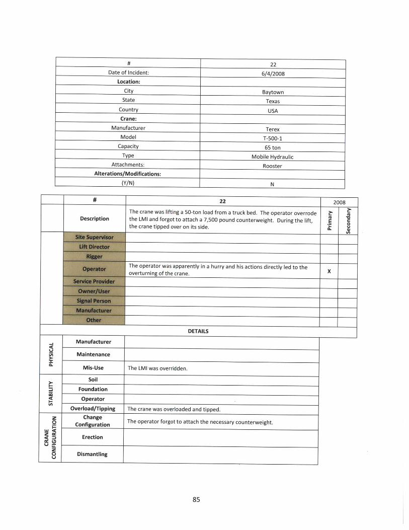
# 22
Date of Incident: 6/4/2008
Location:
City Baytown
State Texas
Country USA
Crane:
Manufacturer Terex
Model T-500-1
Capacity 65 ton
Type Mobile Hydraulic
Attachments: Rooster
Alterations/Modifications:
(Y/N) N
# 22 2008
The crane was lifting a 50-ton load from a truck bed. The operator overrode
Description the LMI and forgot to attach a 7,500 pound counterweight. During the lift, Ethe crane tipped over on its side.
The operator was apparently in a hurry and his actions directly led to theoverturning of the crane.
DETAILS
Manufacturer
Maintenance
Mis-Use The LMI was overridden.
Soil
Foundation
Operator
Overload/Tipping The crane was overloaded and tipped.
z Changeo Configuration The operator forgot to attach the necessary counterweight.
- Ertionz o DmErection
0 Dismantling
85
~14U
0.

# 23
Date of Incident: 5/31/2008
Location:
City Las Vegas
State Nevada
Country USA
Crane:
Manufacturer Manitowoc
Model 2250
Capacity 300 ton
Type Lattice Crawler
Attachments:
Alterations/Modifications:
(Y/N) N
# 23 2008
The lattice boom crawler crane was one of three cranes being used to"shake out" steel in the lay-down area at the direction of the ground
fU 1Description ironworking crew. An oiler was performing his duties and working E
around the crane while it was in operation when he became trapped Wtbetween the counterweights and track as the upperworks rotated.
The lift director must make sure all personnel are clear of the swing path X-of the counterweights prior to allowing the crane to operate
The signal person should immediately tell the operator to stop if Xsomebody is in the path of the crane or load.
The oiler worker should have realized he was in harm's way and eithernot have been there or have told the operator to stop before he moved Xto where he was located.
DETAILS
Signal PersonThe signal person should immediately tell the operator to stop ifsomebody is in the path of the crane or load.
Load Fall
M< Crane The worker was trapped by the crane.
o Load Drift
Maintenance
86
z(z

# 24
Date of Incident: 5/31/2008
Location:
City Wright
State Wyoming
Country USA
Crane:
Manufacturer Lampson
Model Transi-Lift LTL-1100
Capacity 1100 ton
Type Lattice Crawler
Attachments:
Alterations/Modifications:
(Y/N) N
87

24 2008
This crane is considered a mega crane. The crane was lifting a 496,000 poundconveyor at a coal mine. Substantial amounts of rain occurred in the weeks
prior to the lift. The tip/load block was reeved asymmetrically. Tuggers (smallwinches) were used to control load movements. During the lift, the jib became 2
Description side-loaded, buckled, and collapsed, resulting in multiple serious injuries. The
precise cause (or combination of causes) of the incident was unable to be r ,determined without further analysis. However, all of the remaining possible
causes were attributable to the same entity - the lift director and operator of
the crane.
Site conditions (rain and wind) likely contributed to the cause of the collapse. X
Improper reeving and use of tuggers also likely contributed to the cause of the
collapse.
DETAILS
Soil
Foundation
Operator
Overload/Tipping
Some minor soil movement occurred, but was not significant enough to have
caused the collapse by itself.
Stuck LoadzO The tip/load block was asymmetrically reeved, which was not accounted for in
Improper Setup the original design of the equipment. The reeving generated torsional loads in
U the jib not originally accounted for.0 Manual Violation
z:5 The cause is likely a combination of factors under the control of the operatorC. Site Control and lift director.
Failure
Softeners
Unbalanced Improper tensions on one of the two tuggers would have caused side-loading.
Z Wind Wind possibly caused some load drift.
88
J
t-

# 25
Date of Incident: 5/30/2008
Location:
City New York City
State New York
Country USA
Crane:
Manufacturer Kodiak Crane
Model KL-300L-DH
Capacity 16 ton
Type Tower
Attachments:
Alterations/Modifications: I
(Y/N) N
# 25 2008A tower crane was being used to construct a high-rise building. In the weeksprior to the incident, the crane user jumped the crane, which required safetylimit switches to be bypassed. The upper limit switch bypass was never reset.
Description During use, the crane operator two-blocked the crane. When the load line Ebroke, the boom went over backwards, resulting in a complete collapse of the . V
upper section of the crane. Initially suspected "deficient welds" have beenproven to have been sufficient.
The operator two-blocked the crane, resulting in a collapse of the equipment. X
DETAILS
-I
4-Manufacturer
Maintenance
Mis-Use Operator two-blocked crane, causing a backward stability failure of the crane.
Site Control
Wrong WeightPlan Issues
Operator Operator two-blocked crane, causing a backward stability failure of the crane.
Weatherz Change Safety limit switches were bypassed while jumping the crane, and were notj Configuration reset for normal operations. Anti-two-block was disengaged.
Erection
zo DismantlingUi
89

# 26
Date of Incident: 5/23/2008
Location:
City Platte County
State Missouri
Country USA
Crane:
Manufacturer Manitowoc
Model 18000
Capacity 850 ton
Type Lattice Crawler
Attachments:
Alterations/Modifications:
(Y/N) N
# 26 2008
This crane is considered a mega crane. While checking windvelocity on a windy day, the crane operator raised the boom and M -o
Description jib, but did not have the traveling counterweights installed. Crane - 0
tipped over while lowering the boom/jib.
The controlling site contractor did not account for wind velocities Xfor proper crane operations.
Operator raised the boom and jib to check wind speed, while
lowering the boom/jib, the crane tipped over. Did not have the Xcounterweights attached.
DETAILS
Soil
Foundation
Operator
Overload/Tipping Crane tipped while lowering the boom/jib
W Wind speeds were too high, and the operator used theWind anemometer on the jib to check wind speeds.
Load Fall
W g Crane The boom fell on a worker.cc
o Load Drift
Maintenance
90
-
I-

# 27
Date of Incident: 5/21/2008
Location:
City Atlanta
State Georgia
Country USA
Crane:
Manufacturer Liebherr
Model 550 HC
Capacity 40 ton
Type Tower
Attachments:
Alterations/Modifications:
(Y/N) N
# 27 2008
While raising the jacking frame in preparation to jump the tower crane, athe jacking frame operator failed to properly seat the bearing, whichslipped, causing the jacking frame to fall. A worker on board the climber - 0
survived with injuries.
Jacking frame operator (not crane operator) did not completely seat the- -frame before jumping. X
The manufacturer later adjusted their jacking frame bearing design toaccount for the potential of this type situation and minimize the Xpotential for slippage if the frame is not properly operated.
DETAILS
zLU
z0
z0Q
ChangeConfiguration
Erection
Dismantling
Moving jacking frame into position when jacking frame fell
91

# 28
Date of Incident: 5/14/2008
Location:
City Jersey City
State New Jersey
Country USA
Crane:
Manufacturer Potain
Model Unknown
Capacity Unknown
Type Tower
Attachments:
Alterations/Modifications:
(Y/N) N
# 28 2008
A tower crane jib was being disassembled using an assist crane. Riggers
Description did not rig to the jib's center of gravity, and the jib section swung into Eone of the riggers when it was lifted and freed from the rest of the jib. n
Jib wasn't properly rigged for removal X
DETAILS
Failure
Softeners
UnbalancedLoad CG wasn't centered in rigging. The load shifted and impactedworker.
Changeo Configuration
Erection
oa Load CG wasn't centered in rigging. The load shifted and impactedDismantling worker.
92
Wz

# 29
Date of Incident: 4/29/2008
Location:
City Ingleside
State Texas
Country USA
Crane:
Manufacturer Demag
Model CC2800 (4x)
Capacity 600 ton
Type Lattice Crawler
Attachments:
Alterations/Modifications:
(Y/N) N
#_29 2008Four 600-ton cranes were used to hoist a 1200-ton offshore platform float. It wasplanned to hoist and track with the load in order to set the float into a graving dock.During initial hoisting, a structural failure occurred in one of the booms, killing theoperator. The critical lift plan called for a pick & travel with 4 cranes starting at 95% M
Description of capacity, and all of the cranes would have had to travel outward (increase radius) Eto complete the lift. Boom failure occurred while hoisting, most likely due to varied Choisting speeds. The critical lift plan was doomed from the start. The precision it t
required is nearly impossible and an increase in radius is not acceptable whenbeginning at 95%.
Critical lift plan was doomed for failure before lift even started. X
Operators should have refused to perform lift as planned X
DETAILS
-I~1
Li
U
Site Control Crane travel was blocked-had to adjust
Load FallCrane Failed boom fell on operator
0 Z Load DriftMaintenance
93
Wrong Weight
Plan Issues Plan called for pick & travel with 4 cranes starting at 95% of capacity.
OperatorWeather

# 30
Date of Incident: 4/23/2008
Location:
City Woods Cross
State Utah
Country USA
Crane:
Manufacturer Gehl
Model DL12-40
Capacity 6 ton
Type Hydraulic Truck
Attachments: Fork Lift
Alterations/Modifications:
(Y/N) N
# 30 2008
At a refinery, the operator was removing a wire rope with theDescription telescoping truck when he went in reverse without a spotter. His boom E
was raised and it contacted a power line that he did not see.
Operator was supervisor. X
Did not check for overhead obstacles and proceeded without a spotter. X
DETAILS
Operator
Rigger
The operator was removing a wire rope with the telescoping truck whenhe went in reverse without a spotter. His boom was raised and itcontacted a power line that he did not see.
94
a:00.
tz0U

# 31
Date of Incident: 4/16/2008
Location:
City Adelanto
State CA
Country USA
Crane:
Manufacturer Terex
Model T340-1 XL
Capacity 40 ton
Type Hydraulic Truck
Attachments:
Alterations/Modifications:
(Y/N) N
# 31 2008
Workers were working on highway construction in the vicinity of energizedpower lines. No spotters were used. The GC failed to have lines de-energized orblanketed. The crane contacted the power line, and a fire started around the
(U *0Description crane's tires. After initially getting away unharmed, the rigger and operator were E
trying to put out fires when the breakers tripped. At that point in time, theoperator and rigger were touching the crane and operator was electrocuted, and (
two workers were burned by electricity, one while rescuing the other.
General contractor failed to place signage to warn of overhead power lines andfailed to either have turned the power off or blanket the lines.
Rigger was electrified when he tried to put out a fire by kicking dirt onto the fire.He placed his hand in contact with the crane.X
Crane operator was working too close to power lines without verifying if lineswere turned off. He then tried to put out tire fire while grabbing onto the crane. XHe was electrocuted.
DETAILS
Operator
Rigger
Boom section contacted power line.
Workers intentionally touched electrified crane.
95
LI
00.00

# 32
Date of Incident: 3/25/2008
Location:
City Miami
State Florida
Country USA
Crane:
Manufacturer Liebherr
Model 540 HC-L
Capacity 50 ton
Type Tower
Attachments:
Alterations/Modifications:
(Y/N) N
# 32 2008
During the jumping procedures of one of the tower "insert" sections, the 19-foot tower section fell approximately 39 stories to the ground impacting a one-
story house below. Site supervision was supposed to clear the area beneath theDescription crane, but two individuals were in the house where the section fell on them. E 0
The operator was lowering the upper sections while in the process of jumping 0)the crane when the section hanging from the jacking frame got hung up on achord pin. As the upper was lowered, the section became dislodged and fell.
Supervisors failed to clear area beneath crane during jacking procedures X
Lowering section and crane upper when section got hung up on pin, sectionbecame dislodged and fell.
Insufficient instructions regarding lowering upper works while still holding
DETAILS
Wind Wind caused the jumping operation to be aborted, leading to the accident.
z ChangeConfiguration The accident occurred during a tower extension process.
Erectionz0U~ Dismantling
Load Fall The tower section fell and impacted two workers.
Crane
U Load Drift
96

# 33
Date of Incident: 3/23/2008
Location:
City Veracruz
Country Mexico
Crane:
Manufacturer IHI
Model Unknown
Capacity 25 ton
Type Pedestal
Attachments: Electro-hydraulic Grab Bucket
Alterations/Modifications:
(Y/N) N
# 33 2008
There were four mounted pedestal cranes on a ship. While operating one
Description of the cranes, a sudden loss of hydraulic pressure caused the boom todrop to the deck. Inspection revealed a hydraulic failure in the lift - 8
cylinder. Inspections and maintenance had been completely inadequate.
Lack of adequate maintenance led to incident X
DETAILS
Manufacturer
Maintenance Extremely infrequent maintenance (every 3 years) led to hydraulic failure
Mis-Use
97
-I
U)
0.

# 34
Date of Incident: 3/15/2008
Location:
City New York City
State New York
Country USA
Crane:
Manufacturer Favelle Favco
Model M440E
Capacity 30 ton
Type Tower
Attachments:
Alterations/Modifications:
(Y/N) N
# 34 2008
Description
Failure
Softeners
Unbalanced
A tower crane was climbing while holding its support collar in place
when the rigging failed. The master rigger was using nylon slings
attached to the I-beam lacing (as opposed to the tube lacing
members). They were using chain falls to lift the collar when the
rigging was cut. The collar then fell down the tower, shearing off the
previously installed collars below. This led to the total collapse of
the crane causing significant damage to property and multiple
fatalities.
E-~
Supervisor allowed improper rigging techniques X
Lift director allowed improper rigging techniques X
Collar was improperly rigged, and the rigging was cut X
DETAILS
Rigging was secured around wrong lacing on tower sections
z Change Preparations to install collar.- Configuration
z Erection
zO DismantlingU
0U
98
zw

# 35
Date of Incident: 2/9/2008
Location:
City San Bernardino
State California
Country USA
Crane:
Manufacturer Unknown
Model Unknown
Capacity Unknown
Type Gantry
Attachments:
Alterations/Modifications:
(Y/N) N
-rT
Description
35Workers were using a shop-built lifting frame with an overhead/trolleying electrichoist to move a large pump. There were site constraints, and the workerscollectively decided to pull the load off-center. When they pulled the load off- M
E Ccenter, the lifting frame tipped over, the pump fell, and impacted one of the - 8workers. tA
Told workers to, an helped, to pull load off center X
Pulled load off center X
Lifting frame did not have a large enough base X
DETAILS
Failure
Softeners
z2
z
__ Engineering Lifting frame did not have a large enough base
Load Fall
Crane Worker hit by crane
Load Drift
Maintenance
99
Wz
2038
Unbalanced Workers pulled load off center

# 36
Date of Incident: 1/6/2008
Location:
City Gulf of Mexico
State Louisiana
Country USA
Crane:
Manufacturer Superintendent
Model EMC 25
Capacity
Type Pedestal
Attachments:
Alterations/Modifications:
(Y/N) N
# 36 2008
The operator was raising a load when there was a sudden increase
in the load indicator. As he was notifying the crew that the load
Description was stuck, the boom hoist wire rope failed near the outer bridle Ethat was connected to the pendant lines. The lattice boom dropped 0.suddenly onto the top of the swivel and stopped.
The seized sheave and failed boom hoist wire rope was covered
with an excessive amount of grease which significantly affected the Xability to conduct a quarterly inspection. As a result the inspections
DETAILS
Manufacturer I
Maintenance
Mis-Use I
100
U
za-
Failure occurred when the boom hoist wire rope jumped the sheave
and was cut as it extended over the edge of the sheave. The sheave
had not been well maintained and the issue had not been identified

# 37
Date of Incident: 12/26/2007
Location:
City Monrovia
State California
Country USA
Crane:
Manufacturer P&H
Model 9170 TC
Capacity 150 ton
Type Lattice Truck
Attachments:
Alterations/Modifications:
(Y/N) N
# 37 2007
A lattice boom truck crane was used to erect tilt wall panels. Followingcompletion, the crane was moved next to the street for disassembly. The
. boom was taken off and the tip put back. Late in the day, prior to leaving it was "discovered that the counterweights had to be placed on another trailer. The 0
operator tried to make the lift without the outriggers extended. The crane
tipped and the crane fell onto the slab of the building.
Operator failed to extend the outriggers fully while making a lift. X
DETAILS
Soil
Foundation
Operator
Overload/Tipping Operator failed to extend the outriggers fully while making a lift.
z0
z Change Operator failed to extend the outriggers fully while making a lift. At the end of
W (D Configuration dismantling, the operator ran the crane without extending the outriggers.U-Mz0
101
co

# 38
Date of Incident: 12/11/2007
Location:
City Harker Heights
State Texas
Country USA
Crane:
Manufacturer Link Belt
Model HC 248H
Capacity 200 ton
Type Truck Crane
Attachments:
Alterations/Modifications:
(Y/N) N
# 38 2007
A lattice truck crane was erecting precast wall panels. While making a safety
Description video on how to erect precast wall panels, a worker knocked out the wrong Ebrace, and the panel fell over onto an adjacent crane
Told workers to remove the wrong brace X
DETAILS
z0
U.'
0
Load Fall
Crane
Load Drift
Maintenance
Crane was impacted when a worker removed the wrong brace on a concrete
wall panel
102

# 39
Date of Incident: 10/12/2007
Location:
City Grenada
State Mississippi
Country USA
Crane:
Manufacturer Kranco Inc
Model Log Boom
Capacity 40 ton
Type Log Boom Crane
Attachments:
Alterations/Modifications:
(Y/N) N
39 2007
The operator was lifting a load of logs when the crane collapsed. Evidenceindicated that failure initiated at the lower flange connection installed in the
backstay. The crane was brittle from excessive sulfur content and aging. Some
significant overload event likely occurred shortly before the ultimate collapse.
to
-E
There was likely some operational overload before the collapse. X
The crane was aging and may have reached its limit of operation. X
DETAILS
The crane was aging.
There was likely some operational overload before the collapse.
21
C0U-,
103
Description

# 40
Date of Incident: 9/25/2007
Location:
City Lufkin
State Texas
Country USA
Crane:
Manufacturer Yale
Model Yale
Capacity 3 ton
Type Floor operated overhead
Attachments:
Alterations/Modifications:
(Y/N) N
# 40 2007
While operating an overhead crane, the operator maneuvered the crane
Description such that the hooks attached to the crane accidently caught on a 4,000 E
pound flask, knocking it to the ground and contacting the operator. c
-The operator did not adhere to requirements by the manufacturer's
operator manual for proper use of the involved crane. The operating Xmethod was a direct contributing factor in knocking the flask to the
ground.
Labels on the controls were illegible. This was not deemed a contributingfactor in the involved incident because the operator was highly familiar
with the controls.
DETAILS
Load Fall
Crane
Load Drift
Maintenance
An object was knocked by the crane and contacted the worker
104
ILa
0 z0U

# 41
Date of Incident: 9/5/2007
Location:
City San Jose
State California
Country USA
Crane:
Manufacturer Unknown
Model Unknown
Capacity 75 ton
Type Hydraulic Truck
Attachments:
Alterations/Modifications:
(Y/N) N
# 41 2007A hydraulic truck crane was being used to move a generator. Workersattached rigging the generator at the bottom of the generator. The CGwas well above the rigging lift points. The load was lifted, but then
Description flipped and fell. The rigging was attached at the manufacturer's E0
designated lifting points, but the riggers should have followed industry 5standards of avoiding rigging below the CG, especially not with theattachment points so close together.
Riggers lifted the load knowing the pick points were below the CG and it-would flip. X
Tegnrtor manufacturer had the lifting points marked too closetogether, especially when combined with the large dimensions and their Xlocation below the CG
DETAILSPlacement
0-I Stability
The generator manufacturer had the lifting points marked too closetogether, especially when combined with the large dimensions and theirlocation below the CG
FailureNo Softeners
z No Tag LinesWD The generator manufacturer had the lifting points marked too close
Not Balanced together, especially when combined with the large dimensions and theirlocation below the CG. The riggers proceeded anyway.
105
i

# 42
Date of Incident: 8/22/2007
Location:
City Little Rock
State Arkansas
Country USA
Crane:
Manufacturer Terex Comedil
Model CTT 561-20
Capacity 20 ton
Type Tower
Attachments:
Alterations/Modifications:
(Y/N) N
# 42 2007
A tower crane was operating in the blind delivering loads of bricks being usedin the construction of a medical building. The brick masons foreman was
U "aDescription giving directions via radio. While load was being lowered, the foreman E
0walked away and continued signaling the operator. The bricks were lowered e.until one of the laborers was impacted by a pallet of bricks.
The lift director/signal person walked away from a moving load while giving X-signals.
The lift director/signal person walked away from a moving load while giving Xsignals.
DETAILS
Signal PersonThe signal person walked away and did not give the stop command when theload approached a worker.
106
z
Load Fall
Crane
0 Load Drift The load contacted a worker while it was being lowered.
Maintenance

# 43
Date of Incident: 8/10/2007
Location:
City
State Illinois
Country USA
Crane:
Manufacturer Terex
Model T340-1
Capacity 40 ton
Type Hydraulic Truck
Attachments:
Alterations/Modifications:
(Y/N) N
# 43 2007
A mobile hydraulic crane was being dismantled for travel. Twoironworkers were assisting with the outriggers. As the operator was
Description retracting the outrigger, the worker grabbed the outrigger with his arms w
and his arm was crushed. The operator started retracting the outrigger - cand the rigger was next to the crane but did not have his hand/arm inthe assembly until after the retraction started.
The rigger placed his arm in the path of a retracting outrigger. X
DETAILS
z0
SErection/Dismantling The rigger placed his arm in the path of a retracting outrigger during: (D dismantle.U MI
z0
Load Fall
w Crane The rigger placed his arm in the path of a retracting outrigger.: Z
o Load Drift
Maintenance
107

# 44
Date of Incident: 7/16/2007
Location:
City
State Louisiana
Country USA
Crane:
Manufacturer Peiner
Model Peiner
Capacity 20 ton
Type Tower
Attachments:
Alterations/Modifications:
(Y/N) N
# 44 2007
The tower crane was lifting of bundles of reinforcing steel from the groundto the formed deck of a dome approximately 160-180 feet above grade. The Z
(U aDescription lifting operation was a blind pick for the landing of the reinforcement. E
During the landing, a rigger was contacted with the load he was trying to Vcontrol.
Did not use a tag line and had sole responsibility for controlling the load. X
Had a responsibility to give commands to the operator who was working in XEthe blind.
DETAILS
Signal Person I Blind operation. Responsible for where the load goes.
Load Fall
be Crane
0 ~ Load Drift Worker was contacted by the load. No tag line used.
Maintenance
108
I^
zW
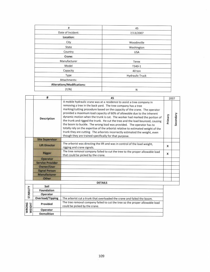
45
Date of Incident: 7/13/2007
Location:
City Woodinville
State Washington
Country USA
Crane:
Manufacturer Terex
Model T340-1
Capacity 40 ton
Type Hydraulic Truck
Attachments:
Alterations/Modifications:
(Y/N) N
45 2007A mobile hydraulic crane was at a residence to assist a tree company inremoving a tree in the back yard. The tree company has a treemarking/cutting procedure based on the capacity of the crane. The operatorprovided a maximum load capacity of 60% of allowable due to the inherent
Description dynamic motion when the trunk is cut. The worker had marked the portion of M Mthe trunk and rigged the trunk. He cut the tree and the load bounced, causing -the boom to buckle. The wrong load was provided. The operator has tototally rely on the expertise of the arborist relative to estimated weight of thetrunk they are cutting. The arborists incorrectly estimated the weight, eventhough they are trained specifically for that purpose.
The arborist was directing the lift and was in control of the load weight,
x-rigging and crane signals.XThe tree removal company failed to cut the tree to the proper allowable load Xthat could be picked by the crane.
DETAILSSoil
FoundationOperator
109
=j
Overload/Tipping The arborist cut a trunk that overloaded the crane and failed the boom.
Provided The tree removal company failed to cut the tree so the proper allowable loadPrve could be picked by the crane.
cc WU Operator
Demolition

# 46
Date of Incident: 7/9/2007
Location:
City Fort Carson
State Colorado
Country USA
Crane:
Manufacturer Manitowoc
Model 888 Series IlCapacity 230 ton
Type Lattice Crawler
Attachments:
Alterations/Modifications:
(Y/N)
46 2007
The construction crew was placing six, pre-cast concrete double tees
measuring 75 feet wide by 568 feet long. Collapse of a precast double tee roof
Description panel was caused when a rigging loop snagged following manual placementoperations and disconnecting the load. The introduction of loading from a - 8single point load from the snag caused forces that destroyed the double tee,
leading to its collapse. This was a blind pick.
The size of the load required a much more difficult lift procedure. A different Xconstruction process may have reduced the difficulty and chance of failure.
The signal person was handling the slings that caused the snag. The signal
person was responsible for being certain that the hooks did not become Xsnagged as he gave the signal to cable up. He gave the "all clear" command
that was the assurance that crane operator relied on to continue cabling up.
DETAILS
Placement I
Stability The load snagged, causing it to be destroyed and collapse.
110
0aJ
The signal person was responsible for being certain that the hooks did not
z Signal Person become snagged as he gave the signal to cable up. He gave the "all clear"
_ ___I command.

# 47
Date of Incident: 7/2/2007
Location:
City Philadelphia
State Pennsylvania
Country USA
Crane:
Manufacturer Manitowoc
Model 2250
Capacity 250 ton
Type Lattice Crawler
Attachments:
Alterations/Modifications:
(Y/N) N
# 47 2007
The incident occurred during the offloading process of a precast concrete
. column which was to be erected for a parking garage. During the lift, the M -aload became stuck on a fire hydrant and the ironworker injured himself -
dislodging the load.
Held responsibility for the lift process that apparently went wrong. X
Ironworker did not need to be involved in dislodging the load. X
DETAILS
Load Fall
Crane
Load Drift The ironworker was injured dislodging the load when it contacted an
object it was not meant to encounter.
Maintenance
111
0x
03:
z0LI

# 48
Date of Incident: 6/19/2007
Location:
City San Antonio
State Texas
Country USA
Crane:
Manufacturer Manitowoc
Model 2250
Capacity 300 ton
Type Lattice Crawler
Attachments:
Alterations/Modifications:
(Y/N) N
48 2007
A new crane was delivered to a power plant. The service technician had set all the
limits including the upper limit which stops the boom at 87 degrees. Several weeks
later during a routine lift, the operator boomed up to 95 degrees and a portion of the -Description E
boom buckled. Soon after, the boom buckled again and fell. It was found that the - Soperator had overridden the limit switch. The operator confessed that he was iroutinely making higher picks than normal and had overridden the device.
The operator overrode the Lattice Boom Hoist Disconnect (Boom Kick Out) and LMI and X
boomed beyond the limits.
DETAILS
Disconnected
Setup
Off
The Lattice Boom Hoist Disconnect (Boom Kick Out) and LMI had been overridden.
Site Control
Wrongz Weight0. No Plan
The crane operator disabled the limit switch and boom up too high causing the boomOperator to buckle.
Weather
112
in
z0
0

# 49
Date of Incident: 6/2/2007
Location:
City Roanoke
State Texas
Country USA
Crane:
Manufacturer Caterpillar
Model 572
Capacity 455 ton
Type Side Boom Pipelayer
Attachments:
Alterations/Modifications:
(Y/N) N
#_ 49 2007
Two side boom pipelayers were attempting to lift a railcar with a transformer inside it back Mtu VDescription onto the tracks. After several attempts, the transformer rocked, striking and cutting the wire E
0rope load line of the side boom resulting in the transformer rolling off the rail car.
Same person as crane operator. Lift was poorly planned and should not have been xattempted.
Same person as crane operator. The load was not secured, as the transformer was notproperly rigged to ensure that it did not become unbalanced. X
Should not have operated with an unstable load. Should also have waited until additionalcranes arrived to ensure they had enough lifting capacity. Ignored other parties' warnings Xthat he did not have sufficient equipment to perform the lift.
DETAILS
0-l
Placement
Site Control
z Wrong Weight
.. Plan Issues The lift required a greater amount of rigging equipment and lifting capacity.
Operator
Weather
Failurez
Softeners The rigging became unbalanced.
2 Unbalanced
113
I
Stability The load was unstable.

# 50
Date of Incident: 6/2/2007
Location:
City Fort Lauderdale
State Florida
Country USA
Crane:
Manufacturer Lorain
Model MC1650 Moto-Crane
Capacity 165 ton
Type Lattice Truck
Attachments:
Alterations/Modifications:
(Y/N) N
# 50 2007
A lattice truck crane tipped over during high winds of a storm in
Fort Lauderdale while 300 feet of boom were extended upward.
No plans were made for a boom laydown area despite knowing
Description that a tropical storm was brewing off the coast. The tropical Estorm hit the west coast of Florida rather than the east coast, et
- but it was reasonable to expect high winds and the boom should
have been lowered.
Erected crane without adequate boom laydown area, which
meant that the operator had no immediately available place to X
boom down.
Did not lay down boom with a tropical storm coming ashore X
DETAILS
Soil
Foundation
OperatorThe operator left the long boom up in the air when a tropical
storm was approaching.
114
-a
I-
Overload/TippingThe operator left the long boom up in the air when a tropicalstorm was approaching.

# 51
Date of Incident: 2/13/2007
Location:
City Charleston
State South Carolina
Country USA
Crane:
Manufacturer Terex
Model HC110
Capacity 110 ton
Type Lattice Crawler
Attachments:
Alterations/Modifications:
(Y/N) N
51 2007
Hospital construction. The crane was re-positioning in order to set A/C units onthe roof. As the operator made several turns in a tight location next to varyingheights in the building. In order to fit, the operator raised the boom to near itsmaximum. During a turn with the boom at high elevation, the crane tipped.
Description Wind analysis indicated that the 22 mph wind gusts reported was not sufficientUto overturn the crane. The boom was at or near its maximum boom angle (80- .
degrees plus). Lattice structures become unstable when near vertical a fast turn t
or if the crawlers jerk the boom will become off-centered and pull the craneover.
Operator traveled with the boom at too high an angle and made sudden turnswith the tracks.X
DETAILS
Soil
Foundation
z IJ Operator Operator traveled with the boom at too high an angle.
- Rigger
115
-I
I-U)
Operator traveled with the boom at too high an angle.
Overload/Tipping
Operator

# 52
Date of Incident: 2/2/2007
Location:
City Corpus Christi
State Texas
Country USA
Crane:
Manufacturer Cleasby
Model Conveyor Boom
Capacity 1 ton
Type Truck-mounted Boom
Attachments:
Alterations/Modifications:
(Y/N) N
# 52 2007
A truck-mounted boom was being used to load shingles onto the roof of M
Description a residential house. Sometime after the shingles were loaded onto the E
roof, the roof and some of the house walls collapsed.
Joists had not been installed in the house, making it an unfit structure on Xwhich to place the load. E
DETAILS
The load was placed on a structure that was not capable of holding thePlacement load.
Stability I
116
a0-J

# 53
Date of Incident: 1/16/2007
Location:
City Port Hueneme
State California
Country USA
Crane:
Manufacturer Link Belt
Model HC278-H
Capacity 300ton
Type Lattice Truck
Attachments:
Alterations/Modifications:
(Y/N) N
# 53 2007
A lattice boom truck crane tipped over while offloading a yacht froma ship. The correct load chart and LMI information were used.However, during the lift, wind forces applied to the side of the yacht
Description caused the yacht to drift away from the crane. As the yacht drifted, M "it increased the radius and caused the crane to tip, with the yacht -
crashing down to the ground underneath it. The wind andsubsequent drift of the load also applied a dynamic load on thecrane.
The lift director determined the wind conditions were safe to
DETAILS
Soil
Foundation
Operator
Overload/TippingThe crane tipped after wind drifted the load and increased theradius.
117
LA
Wind Wind was the primary cause of the collapse.

# 54
Date of Incident: 12/15/2006
Location:
City Calapooia River
State Oregon
Country USA
Crane:
Manufacturer DeMag
Model AC 435
Capacity 150 Ton
Type All Terrain
Attachments:
Alterations/Modifications:
(Y/N) N
# 54 2006
While constructing a bridge, the crane was at 70% capacity, making a dual pick.There was no sudden event, and the boom collapsed. This failure was identical to
M "0
Description another previous failure with the same type of crane the prior week. The radius Eand weight of the load were confirmed to be well within the crane's capacity.The load/configuration was at a reported 70% of the allowable.
There was a boom design defect. X
DETAILS
Manufacturer I The boom failed while only at 70% allowable capacity.
Maintenance
118
-a4I.,
z0.

# 55
Date of Incident: 12/2/2006
Location:
City Cleveland
State Ohio
Country USA
Crane:
Manufacturer American Hoist & Derrick
Model S-10
Capacity Unknown
Type Stiffleg Derrick
Attachments:
Alterations/Modifications:
(Y/N) N
55 2006
Workers were in the process of reeving a stiffleg derrick. The manufacturer'son-site rep directed the erection of the derrick. He decided that the derrickshould be reeved in the air, as opposed to on the ground. They used smalldiameter wire rope to hoist larger diameter rope and reeve. Between the two e
Description ropes, a short piece of wire rope (between diameters) was used to connect theropes grips. The use of the short connector wire rope resulted in an effective akink in the rope system. The grips on the short piece of rope contacted one ofthe sheave guards and was cut. The large diameter rope fell and hit the hoistoperator on the ground.
The way the ropes were planned to be reeved resulted in the failure. X
Rigger used grips that were too small which allowed the load line to pull--__ -_through and drop.
DETAILS
(z Failure The loss of control by the grips dropped the load line on the operator.
z Change0 Configuration
Erection The failure occurred during a reeving process.
zU Dismantling
Load Fall The loss of control by the grips dropped the load line on the operator.Crane
0 Z Load Drift3: Maintenance
119
No SoftenersNo Tag LinesNot Balanced

# 56
Date of Incident: 11/29/2006
Location:
City San Francisco
State California
Country USA
Crane:
Manufacturer Linden Comansa
Model LC140
Capacity 8 ton
Type Tower
Attachments:
Alterations/Modifications:
(Y/N) N
# 56 2006
A 50 pound load fell 10 feet from its rigging and struck a worker. The loadDescription was improperly rigged by the rigger using a basket hitch. 0
Was not using tag lines X
Improperly rigged the load, leading to it falling out. X
Signal person was responsible for giving the signals to the operator and Xensuring he was not directing the load over personnel on the deck.
DETAILlS
Placement
120
0140-J The load fell out of its riggingStability
( Failure The rigging was not appropriate for the liftz
Softeners
Unbalanced

# 57
Date of Incident: 11/13/2006
Location:
City Kenmore
State Washington
Country USA
Crane:
Manufacturer Grove
Model RT75S
Capacity 50 ton
Type Rough Terrain
Attachments:
Alterations/Modifications:
(Y/N) N
# 57 2006
An employee was struck by a falling 40-foot H-pile. The beam was being lifted to avertical position while attached to one end by a mobile crane. There was a suddenrelease of an "E" locking clamp that was attached to the pile. Side loading of the Mu -0
Description locking device was the primary cause of the load release. This was caused by an off- E%_ Ucentered placement of the clamp. Lack of maintenance of the locking clamp as a
noted by the residue build-up in the teeth of the clamp could have exacerbated V
slippage of the device as it was side loaded.
The Lift Director was responsible for ensuring the injured worker had heard hiswarning and had moved from the swing path of the load.
Off-center placement of the clamp (in conjunction with the corresponding off-centercircular scrapes) was the primary cause of load release.
____ ____________DETAILS ____
-J
qJ
=0.
Manufacturer
Maintenance
Mis-Use
The clamp was poorly maintained
W Failure The rigging clamp was not placed properly, leading to loss of load.zwi Softeners
Unbalanced
Load Fall The load fell and struck the worker
g 5 Crane
o Z Load Drift
Maintenance
121
I

# 58
Date of Incident: 11/10/2006
Location:
City Mammoth Lakes
State California
Country USA
Crane:
Manufacturer Grove
Model RT880E
Capacity 80 ton
Type Rough Terrain
Attachments:
Alterations/Modifications:
(Y/N) N
58 2006
A mobile crane was dispatched to a condominium project to lift steel bents onthe roof of the project. The operator was working in the blind and signals wereboth radio and hand signals. There had been prior problems with the radios so
Description the signal person was using both and preferred hand. The signal man gave the Esignal to lower slowly but never countered with a stop either vocal or hand. The 4i
load line became slack and when the riggers were prying the load, it fell off the C
column and hit a workers foot.
Lift director was not consistent with signals and did not watch what was Xhappening with the load.
The rigger was not in the proper position and was performing unsafe work Xpractices.
The Lift Director was also the signal person and did not follow proper protocol Xby not watching the load while he was signaling allowing the lines to go slack.
DETAILS
Signal Person I No signal was given to stop lowering the load.
Load Fall The load fell off of a column it had come to rest on and hit a worker.
W Craneo0z 3 Load Drift
Maintenance
122
z

# 59
Date of Incident: 9/19/2006
Location:
City Aurora
State Colorado
Country USA
Crane:
Manufacturer Manitowoc
Model 4100W
Capacity 230 ton
Type Lattice Crawler
Attachments: 30 foot jib
Alterations/Modifications:
(Y/N) N
59 2006A crawler crane was unloading supplies at a construction site. The crane was outfitted
with a 30 foot jib, lowering the lift capacity to 20,000 pounds. The crane was overloaded
at about 178% of its maximum capacity. Upon final positioning, the load was
Description approximately three feet off the ground when there was a sudden drop of the load of E~. U
about 1 foot and then the jib buckled, dropping the load and overhaul ball to the ground. a. WThe dynamic rebound of the luffing boom and vertical tower caused the tower to snap and
the assembly crashed to the ground.
The lift director/site supervisor had ultimate responsibility for load weight accuracy and
The lift director/site supervisor had ultimate responsibility for load weight accuracy andXtold teoeao h norc egt
Did not use LMI X
DETAILS
Disconnected
Setup
Off LMI was not used.
Site ControlWrong5 Weig The lift director specified the wrong weight, leading to the overload of the crane
.WeightNo Plan
3 OperatorWeatherLoad Fall
Crane A piece of the broken crane contacted the crane operator, causing minor injury0 Z Load Drift
w Maintenance
123
I
z0
,

# 60
Date of Incident: 9/16/2006
Location:
City Newport Beach Bay
State California
Country USA
Crane:
Manufacturer Marion
Model 101m
Capacity 75 ton
Type Mounted Marine Dredger
Attachments: Clamshell Bucket
Alterations/Modifications:
(Y/N) Y
60 2006
The crane was being used for dredging. The converted dredging crane had controls that MDescription were difficult to operate. Allegedly, the operator injured himself while attempting to use E
0the controls. )
Utilizing the glide swing correctly, will reduce the operator's force and movement of thexswing lever and help prevent the operator from over-maneuvering the crane.
The air-activated swing control system did not offer adequate metering precision forrotating the crane for the dredging operation. Other parts of the crane controls were Xappropriate.
The air-activated swing control system did not offer adequate metering precision forrotating the crane. Other parts of the crane controls were appropriate. X
DETAILS
Manufacturer
Maintenance
Mis-Use
The air-activated swing control system did not offer adequate metering precision forrotating the crane for this operation.
124
-J
a.

# 61
Date of Incident: 6/19/2006
Location:
City Silsbee
State Texas
Country USA
Crane:
Manufacturer Shaw-Box
Model Series 800 Hoist
Capacity 5 ton
Type Overhead Crane
Attachments:
Alterations/Modifications:
(Y/N) N
# 61 2006An overhead crane hoist was being used to lift a cart. During the lift, the cart waspulled to the side against manufacturer warnings/industry standards and the linecame out of the drum grooves resulting in it being cut. When the load line was cut, 0
the cart fell and struck a worker.Did not sufficiently train their employees in lift operating. They should have beenstrictly forbidden to attempt a side pull.
Operated the crane when the load was to the side, resulting in a side pull. X
Did not sufficiently train their employees in lift operating. They should have beenstrictly forbidden to attempt a side pull.
DETAILS
CL Manufacturer
Maintenance
Mis-Use The wire rope was cut due to the crane being operated in an inappropriate manner.
Site Control
Wrongz Weight0. Plan Issues
The operator performed a lift when the load was not centered under the free-Operator hanging load line.
Weather
Load Fall The load fell and struck a worker.Crane
O Z Load DriftMaintenance
125
I

# 62
Date of Incident: 5/7/2006
Location:
City Los Angeles
State California
Country USA
Crane:
Manufacturer Liebherr
Model 630 EC-H
Capacity 20 ton
Type Tower
Attachments:
Alterations/Modifications:
(Y/N) N
62 2006
A technician was erecting a crane and was ready to reeve the load line. Thesystem had an automatic reeving system and the technician did not bring
the correct tools up on the tower. He decided to continue the operationwithout the required tools. The load line hoist drum began to spin out of
. control and caught a man's leg in the rope, cutting it off. At some point as "n oDescription he was placing the wire rope on the deck of the boom, sufficient slack - 0
developed that it started to pull the rope coiled on that deck. The otherworker was standing on the moveable work basket and may have tried tostep on the rope to keep it from running out. The rope caught his leg andpulled him into the boom.
The technician failed to follow proper procedures and was directing the Xoperations.
DETAILS
Erection/Dismantling The technician failed to follow proper procedures
Load Fall
Ui Crane
o Z Load Drift
Maintenance During erection a worker was caught in the hoist rope automatic reevingsystem.
126
z
U
z0
z0U

# 63
Date of Incident: 3/30/2006
Location:
City Salem
State Virginia
Country USA
Crane:
Manufacturer Grove
Model TMS
Capacity 30 ton
Type Hydraulic Truck
Attachments:
Alterations/Modifications:
(Y/N) N
# 63 2006At a tool factory, a crane company was hired to lift a 17,500 pound lathe.During the lifting operations the slings failed and the load fell. The lathe Mwas re-rigged and the slings failed again. The lathe was re-rigged a third E
0time with wire ropes at the request of the crane operator and the lift wassuccessful.
The lift director was responsible for the riggers. X
The riggers failed to provide softeners for the nylon slings. Additionally,improper rigging of the slings in a choker configuration overloaded the Xslings.
DETAILS
The rigging was done improperly twice.
The riggers failed to provide softeners.
127
Description

# 64
Date of Incident: 1/17/2006
Location:
City Waco
State Texas
Country USA
Crane:
Manufacturer Budgit Hoists
Model Electric Chain Hoists
Capacity 2 ton
Type Overhead Crane
Attachments:
Alterations/Modifications:
(Y/N) N
# 64 2006
A worker was rigging and lifting an approximately 80-foot-long catwalk with one of
Description two overhead cranes. The catwalk disengaged from the hook and impacted a E rworker sweeping the floor under the load. 0
Failed to adequately train all employees in overhead crane operation. X
The rigger is responsible for ensuring proper engagement of the hardware in order
to ensure that a load will not become disengaged from the rigging. The primary Xcause of the incident was that the rigger did not ensure proper engagement of the
-rigging hardware
Failed to ensure that he was not lifting the suspended load above personnel. X
DETAILS
Site Control
Weather
Failure Rigger did not engage the rigging hardware.z
Softeners
Unbalanced
Load Fall The load fell and hit a worker.
Crane
a Load DriftMaintenance
128
z WrongWeight
Plan IssuesDid not follow practice of not lifting over people.Operator

# 65
Date of Incident: 12/22/2005
Location:
City Pineland
State Texas
Country USA
Crane:
Manufacturer LeTourneau
Model JC-40
Capacity 20 ton
Type Pedestal
Attachments: Grapple
Alterations/Modifications:
(Y/N) Y
65 2005
The pedestal crane was used to off-load logs from trucks and stack them in acircular configuration around the tower column and then place them forpreparation for the mill. The crane was originally operated sparingly, butrecently had been relocated for heavier use. A service company was hired to Mdismantle, refurbish/modify, upgrade, and erect the crane at the new site. - 0Four years later the crane collapsed. Post collapse inspection revealed t
imperfections, cracks, corrosion and damage to the crane which was a directcontributor to the ultimate collapse as a result of fatigue.
When they refurbished the crane, the service provider was responsible forensuring the crane was capable of meeting governing national standards onceplaced back in operation. They failed to assess the issues with the crane.They also were responsible for maintenance up until the time of collapse.
DETAILS
Manufacturer
129
-I
UIn
=a. Maintenance i The crane had several maintenance issues that led to its collapse from fatigue.

# 66
Date of Incident: 10/24/2005
Location:
City Hallandale Beach
State Florida
Country USA
Crane:
Manufacturer Liebherr
Model 200-HC
Capacity 10 ton
Type Tower
Attachments:
Alterations/Modifications:
(Y/N) N
# 66 2005
A tower crane was being used to construct a high-rise building. An impendinghurricane required that the crane be properly prepared and vaned prior to the
Description leaving the crane. Reportedly, the operator left one swing brake secured. The 1-tower crane was braced at two locations back to the concrete structure. During - 0
the storm, the upper brace connection pulled out of the concrete allowing the
upper portion to fail in torsion and collapse to the ground.
The operator left one of the swing brakes on. X
The engineer did not provide the proper design for the attachment of the crane Xinto the post tensioned slab. There was no shear reinforcement.
DETAILS
Stuck Load
ImproperSetup
ManualViolation The operator left one of the swing brakes on.
z2 ngnern The engineer did not provide the proper design for the attachment of the crane
winto the post tensioned slab. There was no shear reinforcement.
z
z Wind High winds during a hurricane overstressed the attachment points.
130
'az
V)z0
0.
0

# 67
Date of Incident: 9/8/2005
Location:
City Fort Lauderdale
State Florida
Country USA
Crane:
Manufacturer Manitowoc
Model 888 Series 11
Capacity 230 ton
Type Lattice Crawler
Attachments: Luffer
Alterations/Modifications:
(Y/N) N
#67 2005
The crawler crane was booming down in preparation for a lift when itDescription began tipping over. As a result of the tipping, the crane's luffing E 0
attachment fell and contacted an adjacent building.
The timber mats were installed incorrectly. X
Did not appropriately plan the lift. X
The boom angle, radius, and boom length were outside of themanufacturer chart limits.A
DETAILS
Soil
Overload/Tipping
The timber mats were installed incorrectly.
The crane was overloaded, causing it to tip.
131
I-
Foundation
Operator Operated the crane outside its chart limits.

# 68
Date of Incident: 7/11/2005
Location:
City Fort Worth
State Texas
Country USA
Crane:
Manufacturer Grove
Model TMS-750B
Capacity 50 ton
Type Hydraulic Truck
Attachments:
Alterations/Modifications:
(Y/N) N
68 2005
The operator was holding a suspended load for an hour and a half while workerswere replacing a spring. The lift director did not address the load on the line andthe potential for a stuck load while instructing the riggers to cut a bolt to releasethe load. The load was suspended and the operator was given instructions on
(U VDescription how much pressure to put on the line, pulling up. When the bolt was cut, the load E .r 0
jumped up and drifted over, pinning the riggers hand. While trying to hoist up,and then boom up to lift the load off his hand, the boom buckled. The rigger hadplaced his hand in a potential pinch point knowing the load was under pressureand currently partially suspended.
Did not block the load to prevent slippage while replacing springs X
Placed his hand in a pinch point X
DETAILS
Failure
Softeners
Load Fall
Crane
Load Drift Worker placed himself and his hand under a partially suspended load
Maintenance
132
0zw5
Load wasn't blocked against unintentional movementUnbalanced

# 69
Date of Incident: 6/13/2005
Location:
City Tom Green County
State Texas
Country USA
Crane:
Manufacturer International
Model 2002
Capacity 8 ton
Type Gin Pole Truck
Attachments:
Alterations/Modifications:
(Y/N) N
# 69 2005
Workers were using a gin truck to dismantle an oil rig. During a lift, a. rigger was hanging onto an unbalanced load when it shifted and became M -
much more unbalanced. The sudden shift of the load threw the rigger - Cinto the air.
The rigger failed to balance the load and the imbalance was worsenedwhen he placed his weight on top of the light end. Ensuring balance of a Xoad is a primary responsibility of the rigger/swamper in all lifts.
DETAILS
Placement
Stability
133
00 The load was not balanced and it was made worse by actions of rigger.
W FailurezW Softeners
2 Unbalanced The load was not balanced when it was rigged.

# 70
Date of Incident: 5/23/2005
Location:
City Port Fourchon
State Louisiana
Country USA
Crane:
Manufacturer Manitowoc
Model 888 Series i
Capacity 230 ton
Type Lattice Crawler
Attachments:
Alterations/Modifications:
(Y/N) N
# 70 2005
Risers were being transferred at a port from barges to work boats. During one of
.s i . the lifts the crane tipped due to the load being beyond the allowable load radius. M -Description The lift director/site supervisor instructed the operator to boom down and swing. -
It was a blind pick in the dark.S
Was in charge of site and was giving signals. X
Was in charge of the lift and was giving signals. X
The operator had to rely on the signals given by the signal man. X
DETAILS
Solo
Foundation
Operator
Overload/Tipping The crane boomed beyond its allowable radius and tipped.
Site Control The site supervisor was in charge of the lift and was giving the signals.
&nz Wrong Weight5a. No Plan
Operator
Weather
z Signal Person The operator had to rely on the signals given by the signal man.
134
MI

# 71
Date of Incident: 2/24/2005
Location:
City Bowie
State Texas
Country USA
Crane:
Manufacturer Link Belt
Model LS-108H 11
Capacity 50 ton
Type Lattice Crawler
Attachments:
Alterations/Modifications:
(Y/N) N
71 2005
A lattice boom track crane was being prepared for unloading and erecting a drilling
rig. During the move, the load line needed to be re-reeved. Journeyman and
apprentice riggers were in the hole threading the wire rope back onto the spool.
Description The journeyman performed the task the first time but while they were getting off Ethe crane, the wire "bird-nested" again. The apprentice got back into the spool hole '
and rethreaded. As he was standing on the deck watching the line, he either
stumbled or fell into the hole and got his leg trapped in the winch.
Rigger lost his balance and fell into the crane's hole, becoming trapped by the Xwinch.
DETAILS
ChangeConfiguration
Erection
Dismantling
Maintenance being performed during erection.
Load Fallcc t3
Crane
0 Load Drift
Maintenance Worker re-threading the load line was caught in the spool.
135
z0
UJz
z0U
U6 1

# 72
Date of Incident: 11/18/2004Location:
City Cedar Crest
State New Mexico
Country USA
Crane:
Manufacturer Manitex
Model M2592Capacity 25 ton
Type Hydraulic Truck
Attachments:
Alterations/Modifications:
(Y/N) N
72 2004
A crane was placing a roof beam of a two-story building. The general contractorprovided their own 4-inch nylon sling chokers to secure the ends of the beam tothe hook of the crane. The lift director had discussed and taught the riggers the -
Description procedure required to rig a glue-lam beam. The riggers were responsible for the Erigging. The rigging was inadequate, with one sling that was slack. The beamsuddenly moved from the pocket because it was snagged. The beam fell and aworker had to jump out of the way.
Was responsible for teaching the riggers how to rig the beam properly. X
Did not properly rig the beam, leading to loss of load. X
DETAILS
136
Wz Failure
Softeners
Unbalanced The rigging was not done properly, leading to an unbalanced load.

# 73
Date of Incident: 11/15/2004
Location:
City Winfield
State West Virginia
Country USA
Crane:
Manufacturer Manitowoc
Model 999
Capacity 250ton
Type Lattice Crawler
Attachments:
Alterations/Modifications:
(Y/N) N
73 2004
The crew had to move two cribbing tables into an area below a large steel ductand under the two beams. The crane lifted the load over to the edge of the
. . building and the workers pushed the table to a certain point under the duct M -astructure. A worker slipped while his foot was located in a pinch point. The other 0
two workers were unable to hold the load, allowing it swing back toward theworker, pinching his foot between the suspended load and stationary object.
Had responsibility to keep area clear of dangers and warn workers of danger. X
The rigger created the situation by placing his foot in a very visibly dangerousarea. His ability to control his portion of the load was also affected.
DETAILS
Load Fall
Crane
Load Drift The load drifted when a rigger lost control of his portion of the load when hestepped in a dangerous location.
Maintenance
137
W
0 z0

# 74
Date of Incident: 10/20/2004
Location:
City Galveston
State Texas
Country USA
Crane:
Manufacturer Hagglunds
Model Unknown
Capacity 45 ton
Type Overhead
Attachments:
Alterations/Modifications:
(Y/N) N
74 2004
An overhead crane installed on a ship was being used to off load large food pallets.The experienced operator was lifting his third or fourth bundle when the cranecollapsed. The bolts securing one set of the bogies (an assembly of two or moreaxles arranged to permit vertical wheel displacement and equalize the loading on
Description the wheels) had failed and dropped the entire crane along with the operator who E0
was killed. The sole cause of this accident was a lack of maintenance. The boltthreads were so corroded that the tension applied by the moving crane strippedthe threads off. The crane was approximately 8 to 10 years old and did not appearto have ever been maintained.
The owner did not maintain the crane, leading to its deterioration and collapse. X
DETAILS
Manufacturer
Maintenance There was an extreme lack of maintenance, leading to a collapse.
Load Fall
t Crane Operator fell with the crane as it collapsed.
Load Drift
Maintenance
138
-aCL

# 75
Date of Incident: 10/6/2004
Location:
City South Boston
State Massachusetts
Country USA
Crane:
Manufacturer Manitowoc
Model 777T Series 11
Capacity 200 ton
Type Lattice Truck
Attachments:
Alterations/Modifications:
(Y/N) N
# 75 2004
A contractor was shaking out steel on a commercial construction site. The MDescription jib wasn't properly reeved, and the LMI wasn't properly set up. The jib was E
overloaded and sustained a structural failure and collapsed.
Operator did not familiarize himself with the crane before operating X
Owner reeved the jib line wrong, and didn't properly program the LMI X
DETAILS
ChangeConfiguration
Erection
Dismantling
Initial setup was wrong. The jib line was reeved wrong and the LMI wasn'treading the load.
139
Z0
Z0QzAZ.
Related Documents