INSTITUTE OF AERONAUTICAL ENGINEERING (Autonomous) ANALYSIS OF AIRCRAFT STRUCTURES B TECH IV SEMESTER (R16) Department of Aeronautical Engineering Prepared by Dr Y B Sudhir Sastry Professor Source from Aircraft Structures by T. H. G. Megson

Welcome message from author
This document is posted to help you gain knowledge. Please leave a comment to let me know what you think about it! Share it to your friends and learn new things together.
Transcript
INSTITUTE OF AERONAUTICAL ENGINEERING(Autonomous)
ANALYSIS OF AIRCRAFT STRUCTURES B TECH IV SEMESTER (R16)
Department of Aeronautical Engineering
Prepared by
Dr Y B Sudhir Sastry
Professor
Source from Aircraft Structures by T. H. G. Megson
Unit – I
INTRODUCTION TO AIRCRAFT STRUCTURAL COMPONENTS
AND ENERGY METHODS
Aircraft Structural components and loads
Aircraft are generally built up from the basic components of wings,fuselages, tail units and control surfaces
The structure of an aircraft is required to support
1 ground loads: includes all loads encountered by the aircraft duringmovement or transportation on the ground such as taxiing and landingloads, towing and hoisting loads
2 air loads: comprises loads imposed on the structure during flight bymanoeuvres and gusts.
INTRODUCTION TO AIRCRAFT STRUCTURAL COMPONENTS AND ENERGY METHODS
Source from Aircraft Structures by T. H. G. Megson
Aircraft designed for a particular role encounter loads peculiar to theirsphere of operation.
Carrier born aircraft, for instance, are subjected to catapult take-off andarrested landing loads
Most large civil and practically all military aircraft have pressurized cabins forhigh altitude flying;
Amphibious aircraft must be capable of landing on water and aircraftdesigned to fly at high speed at low altitude,
Ex. The Tornado, require a structure of above average strength to withstandthe effects of flight in extremely turbulent air.
Source from Aircraft Structures by T. H. G. Megson
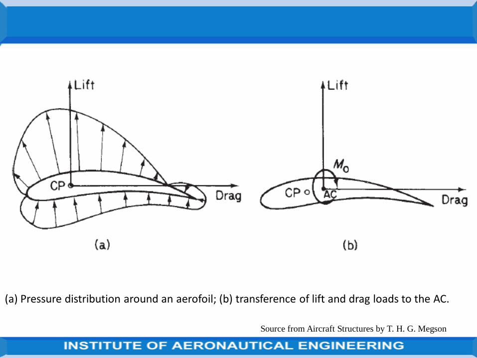
The two classes of loads may be further divided into surface forces whichact upon the surface of the structure,
e.g. aerodynamic and hydrostatic pressure, and body forces which act overthe volume of the structure and are produced by gravitational and inertialeffects.
Calculation of the distribution of aerodynamic pressure over the varioussurfaces of an aircraft’s structure is presented in numerous texts onaerodynamics and will therefore not be attempted here.
We shall, however, discuss the types of load induced by these variouseffects and their action on the different structural components.
Source from Aircraft Structures by T. H. G. Megson

Source from Aircraft Structures by T. H. G. Megson
Principal aerodynamic forces on an aircraft during flight.
Source from Aircraft Structures by T. H. G. Megson
(a) Pressure distribution around an aerofoil; (b) transference of lift and drag loads to the AC.
Source from Aircraft Structures by T. H. G. Megson
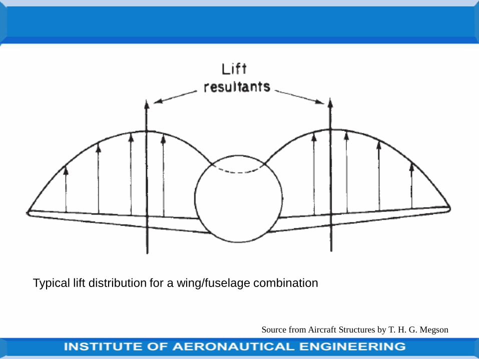
Typical lift distribution for a wing/fuselage combination
Source from Aircraft Structures by T. H. G. Megson
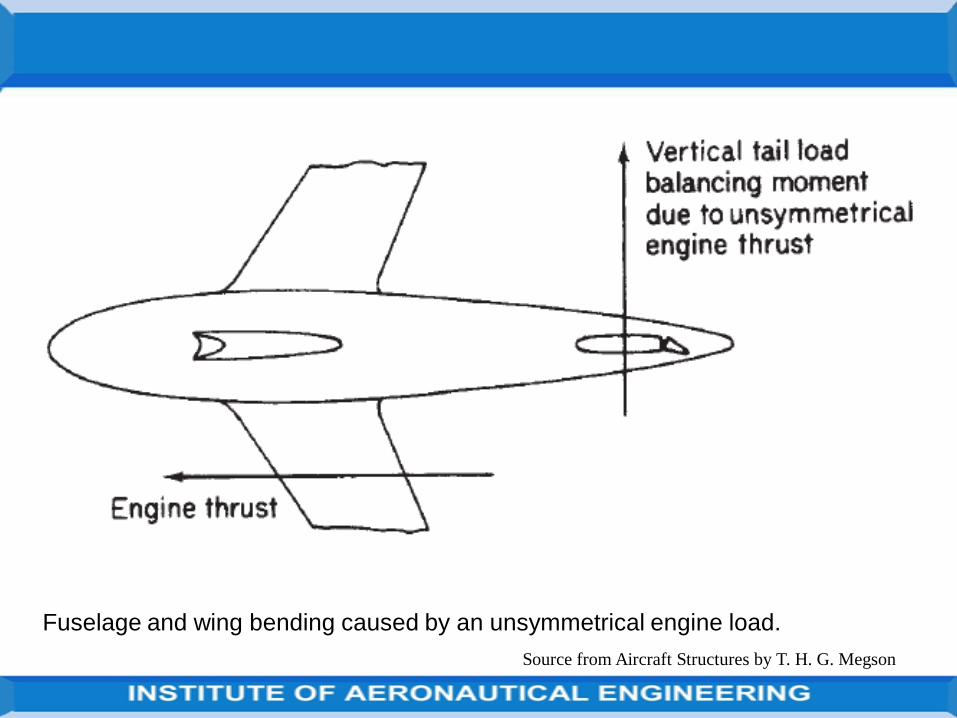
Fuselage and wing bending caused by an unsymmetrical engine load.
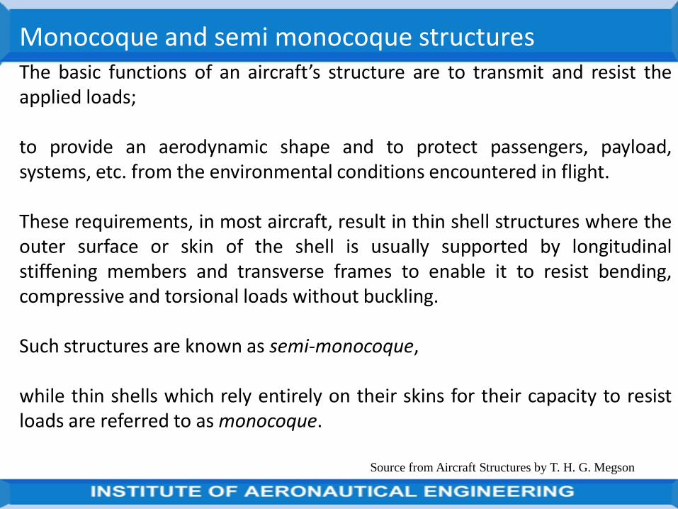
The basic functions of an aircraft’s structure are to transmit and resist theapplied loads; to provide an aerodynamic shape and to protect passengers,payload, systems, etc. from the environmental conditions encountered inflight.
These requirements, in most aircraft, result in thin shell structures wherethe outer surface or skin of the shell is usually supported by longitudinalstiffening members and transverse frames to enable it to resist bending,compressive and torsional loads without buckling.
Such structures are known as semi-monocoque, while thin shells which relyentirely on their skins for their capacity to resist loads are referred to asmonocoque.
Source from Aircraft Structures by T. H. G. Megson

Source from Aircraft Structures by T. H. G. Megson
De Havilland Canada Twin Otter (courtesy of De Havilland Aircraft of Canada Ltd.).
Source from Aircraft Structures by T. H. G. Megson
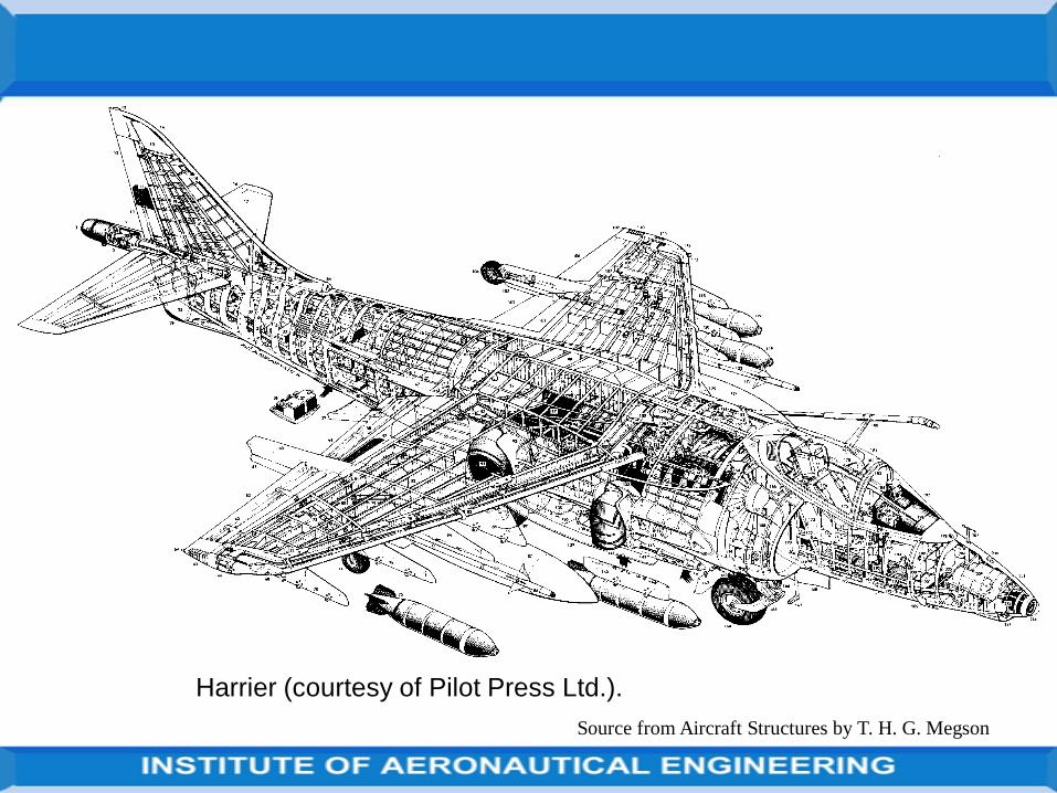
Harrier (courtesy of Pilot Press Ltd.).
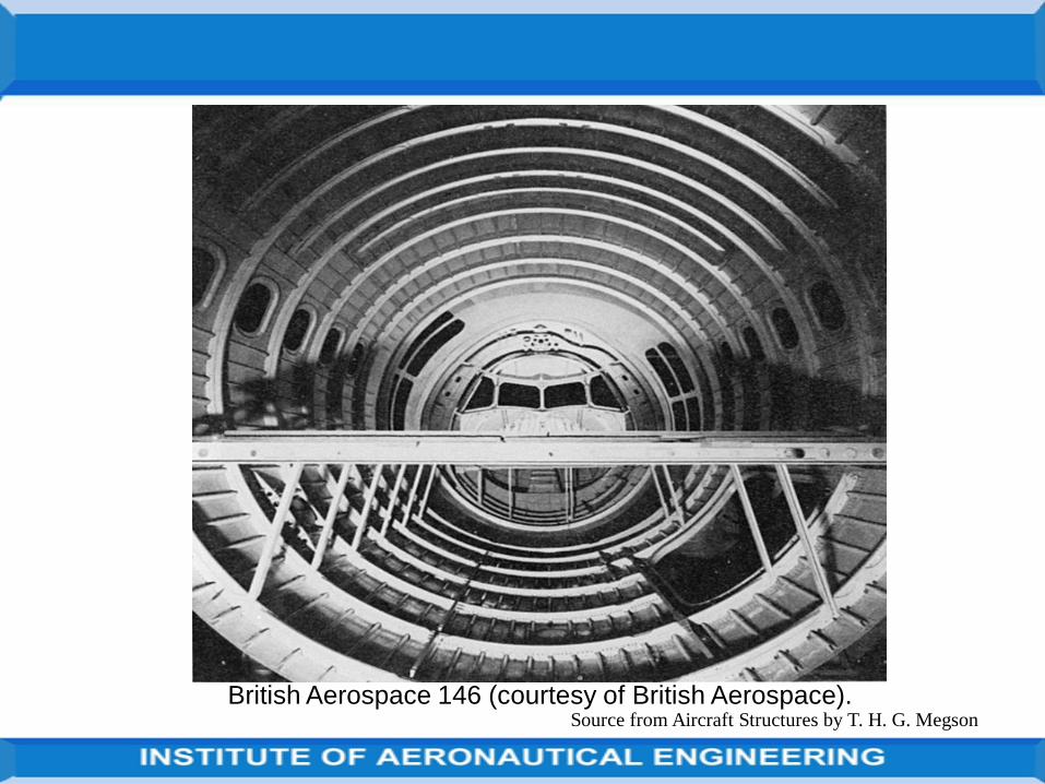
Source from Aircraft Structures by T. H. G. MegsonBritish Aerospace 146 (courtesy of British Aerospace).
No matter how complex the internal structural arrangement the differentcomponents perform the same kind of function.
The shape of the cross-section is governed by aerodynamic considerationsand clearly must be maintained for all combinations of load; this is one ofthe functions of the ribs.
They also act with the skin in resisting the distributed aerodynamic pressureloads; they distribute concentrated loads
(e.g. undercarriage and additional wing store loads)
into the structure and redistribute stress around discontinuities, such asundercarriage wells, inspection panels and fuel tanks, in the wing surface.
Source from Aircraft Structures by T. H. G. Megson
Ribs increase the column buckling stress of the longitudinal stiffeners byproviding end restraint and establishing their column length; in a similarmanner they increase the plate buckling stress of the skin panels.
The dimensions of ribs are governed by their spanwise position in the wingand by the loads they are required to support.
In the outer portions of the wing, where the cross-section may be relativelysmall if the wing is tapered and the loads are light, ribs act primarily asformers for the aerofoil shape.
A light structure is sufficient for this purpose whereas at sections closer tothe wing root, where the ribs are required to absorb and transmit largeconcentrated applied loads, such as those from the undercarriage, enginethrust and fuselage attachment point reactions, a much more ruggedconstruction is necessary.
Source from Aircraft Structures by T. H. G. Megson

Between these two extremes are ribs which support hinge reactions fromailerons, flaps and other control surfaces, plus the many internal loads fromfuel, armament and systems installations.
The primary function of the wing skin is to form an impermeable surface forsupporting the aerodynamic pressure distribution from which the liftingcapability of the wing is derived.
These aerodynamic forces are transmitted in turn to the ribs and stringersby the skin through plate and membrane action.
Resistance to shear and torsional loads is supplied by shear stressesdeveloped in the skin and spar webs, while axial and bending loads arereacted by the combined action of skin and stringers.
Source from Aircraft Structures by T. H. G. Megson
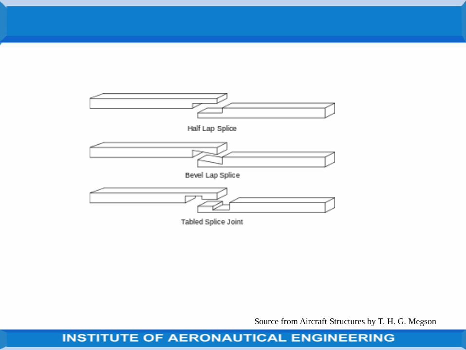
Types of structural joints
The fuselage structure generally consists of skin panels joined directly tothe structural members such as frames, stringers for longitudinal splices.In assembling process critical structures like military or commercialaircraft, riveted or bolted joints are basically used as they offer manyoptions to the engineer.
(source:https://www.google.co.in/search?source=hp&ei=OgH8WtqUMYLI0gSpsKi4BQ&q=types+of+structural+joints+in+aircraft&oq=Types+of+structural+joints&gs_l=psy-ab.1.1.35i39k1j0j0i22i30k1l8.8846.8846.0.10736.3.2.0.0.0.0.176.176.0j1.2.0....0...1c.1.64. psy-ab..1.2.348.6...172.muPwFe8AWP8)
Source from Aircraft Structures by T. H. G. Megson

The fabrication of aircraft components generally involves the joining of onepart of the component to another.
For example, fuselage skins are connected to stringers and frames whilewing skins are connected to stringers and wing ribs unless, as in somemilitary aircraft with high wing loadings, the stringers are machinedintegrally with the wing skin.
With the advent of all-metal, i.e. aluminium alloy construction, rivetedjoints became the main form of connection with some welding althoughaluminium alloys are difficult to weld, and, in the modern era, some gluedjoints which use epoxy resin.
In this section we shall concentrate on the still predominant method ofconnection, riveting.
Source from Aircraft Structures by T. H. G. Megson
In general riveted joints are stressed in complex ways and an accurateanalysis is very often difficult to achieve because of the discontinuities inthe region of the joint.
Fairly crude assumptions as to joint behaviour are made but, whencombined with experience, safe designs are produced.
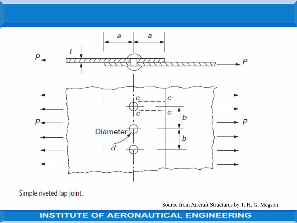
Figure shows two plates of thickness t connected together by a single lineof rivets; this type of joint is termed a lap joint and is one of the simplestused in construction.
Suppose that the plates carry edge loads of P/unit width, that the rivetsare of diameter d and are spaced at a distance b apart, and that thedistance from the line of rivets to the edge of each plate is a.
There are four possible modes of failure which must be considered asfollows:
Source from Aircraft Structures by T. H. G. Megson
Source from Aircraft Structures by T. H. G. Megson
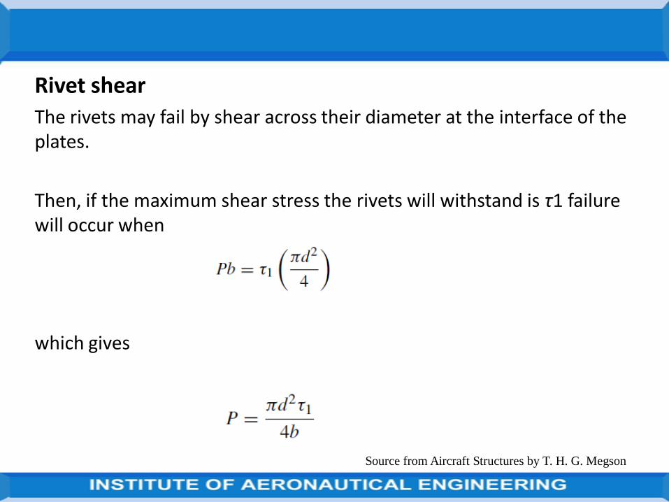
Rivet shear
The rivets may fail by shear across their diameter at the interface of the plates.
Then, if the maximum shear stress the rivets will withstand is τ1 failure will occur when
which gives
Source from Aircraft Structures by T. H. G. Megson
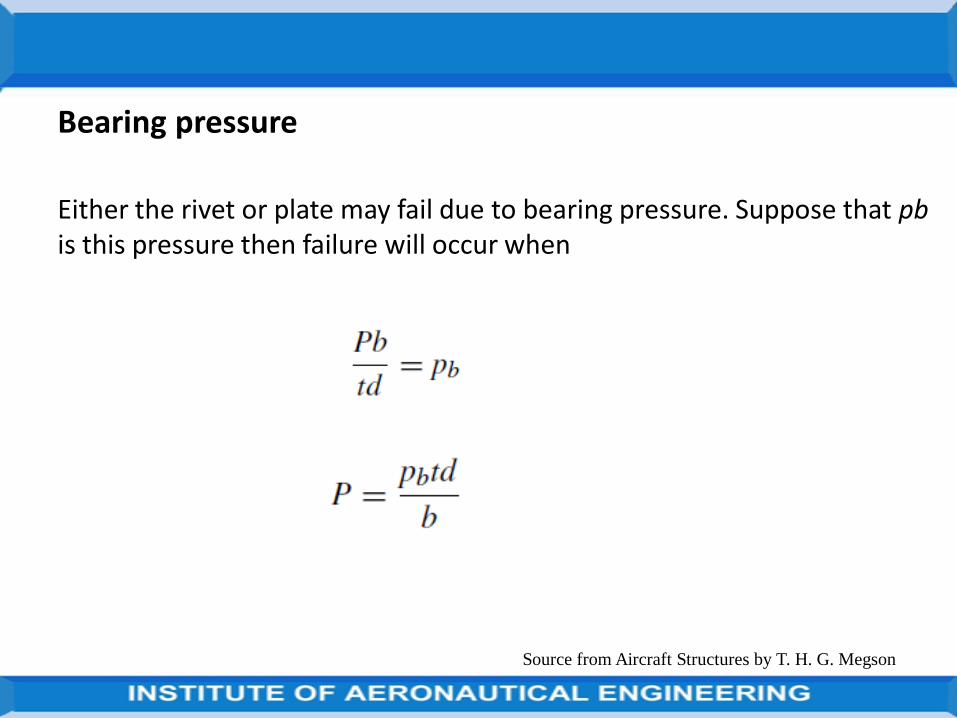
Bearing pressure
Either the rivet or plate may fail due to bearing pressure. Suppose that pbis this pressure then failure will occur when
Source from Aircraft Structures by T. H. G. Megson
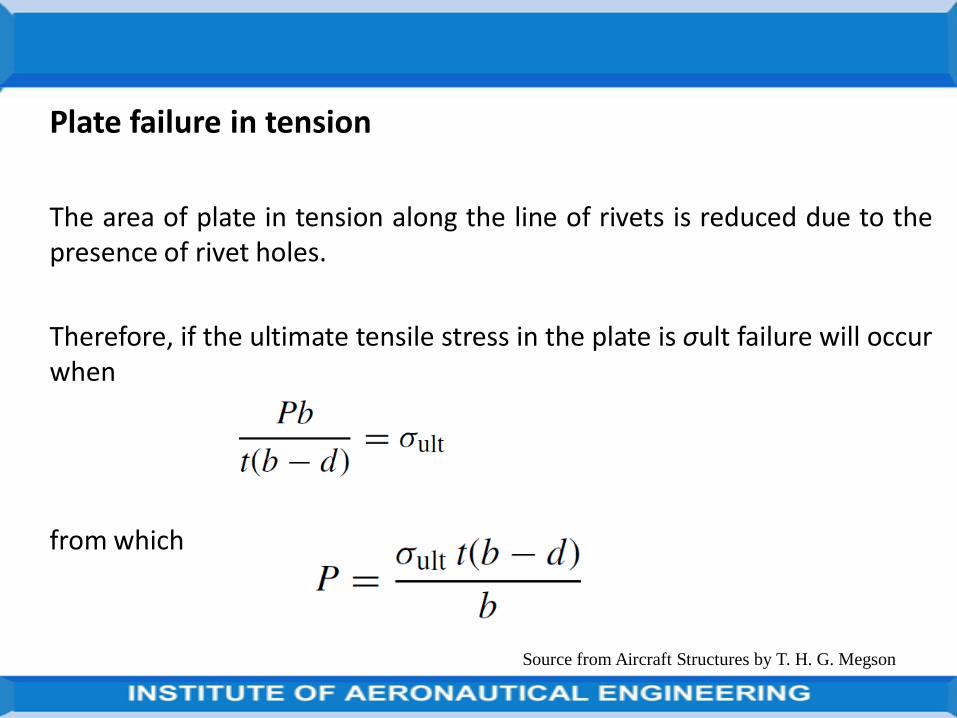
Plate failure in tension
The area of plate in tension along the line of rivets is reduced due to thepresence of rivet holes.
Therefore, if the ultimate tensile stress in the plate is σult failure will occurwhen
from which
Source from Aircraft Structures by T. H. G. Megson
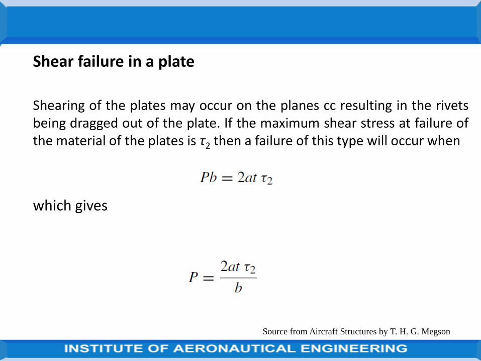
Shear failure in a plate
Shearing of the plates may occur on the planes cc resulting in the rivetsbeing dragged out of the plate. If the maximum shear stress at failure ofthe material of the plates is τ2 then a failure of this type will occur when
which gives
Source from Aircraft Structures by T. H. G. Megson
Source from Aircraft Structures by T. H. G. Megson
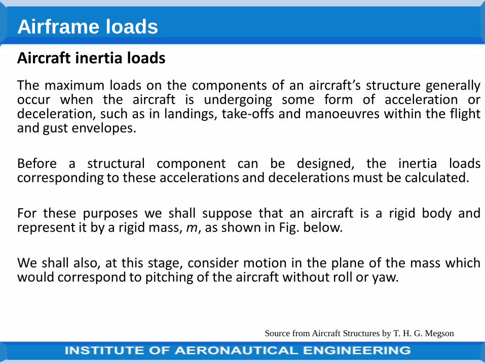
Aircraft inertia loads
The maximum loads on the components of an aircraft’s structure generallyoccur when the aircraft is undergoing some form of acceleration ordeceleration, such as in landings, take-offs and manoeuvres within the flightand gust envelopes.
Before a structural component can be designed, the inertia loadscorresponding to these accelerations and decelerations must be calculated.
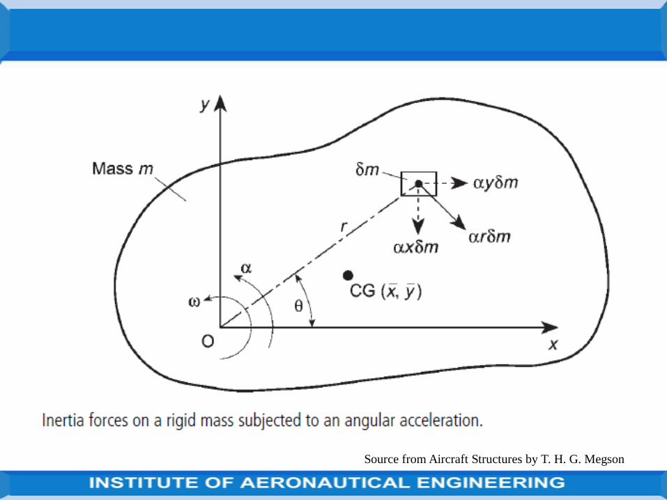
For these purposes we shall suppose that an aircraft is a rigid body andrepresent it by a rigid mass, m, as shown in Fig. below.
We shall also, at this stage, consider motion in the plane of the mass whichwould correspond to pitching of the aircraft without roll or yaw.
Source from Aircraft Structures by T. H. G. Megson
Airframe loads
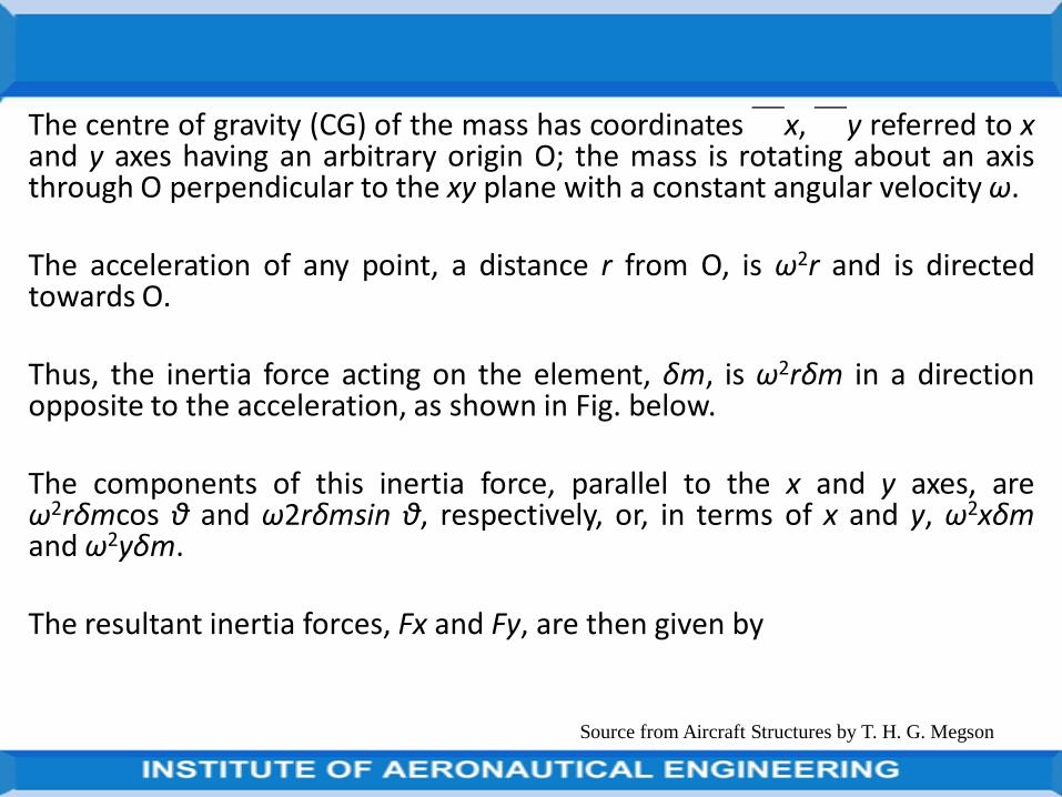
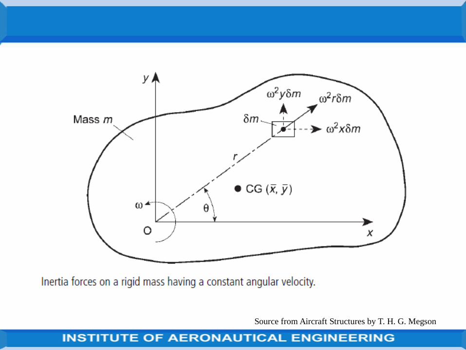
The centre of gravity (CG) of the mass has coordinates  ̄x,  ̄y referred to xand y axes having an arbitrary origin O; the mass is rotating about an axisthrough O perpendicular to the xy plane with a constant angular velocity ω.
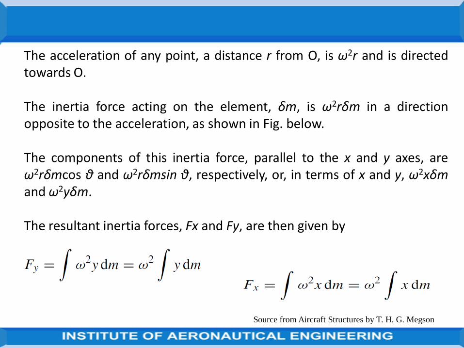
The acceleration of any point, a distance r from O, is ω2r and is directedtowards O.
Thus, the inertia force acting on the element, δm, is ω2rδm in a directionopposite to the acceleration, as shown in Fig. below.
The components of this inertia force, parallel to the x and y axes, areω2rδmcos θ and ω2rδmsin θ, respectively, or, in terms of x and y, ω2xδmand ω2yδm.
The resultant inertia forces, Fx and Fy, are then given by
Source from Aircraft Structures by T. H. G. Megson
Source from Aircraft Structures by T. H. G. Megson
The acceleration of any point, a distance r from O, is ω2r and is directedtowards O.
The inertia force acting on the element, δm, is ω2rδm in a directionopposite to the acceleration, as shown in Fig. below.
The components of this inertia force, parallel to the x and y axes, areω2rδmcos θ and ω2rδmsin θ, respectively, or, in terms of x and y, ω2xδmand ω2yδm.
The resultant inertia forces, Fx and Fy, are then given by
Source from Aircraft Structures by T. H. G. Megson
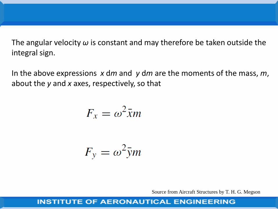
The angular velocity ω is constant and may therefore be taken outside the integral sign.
In the above expressions x dm and y dm are the moments of the mass, m, about the y and x axes, respectively, so that
Source from Aircraft Structures by T. H. G. Megson
Source from Aircraft Structures by T. H. G. Megson
Consider the calculation of aircraft loads corresponding to the flightconditions specified by flight envelopes.
There are infinite number of flight conditions within the boundary of theflight envelope although, structurally, those represented by the boundaryare the most severe.
In symmetric manoeuvres we consider the motion of the aircraft initiatedby movement of the control surfaces in the plane of symmetry.
Examples of such manoeuvres are loops, straight pull-outs and bunts, andthe calculations involve the determination of lift, drag and tailplane loads
at given flight speeds and altitudes.
Source from Aircraft Structures by T. H. G. Megson
Symmetric manoeuvre loads
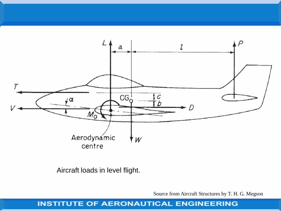
Steady level flight is not a manoeuvre in the strict sense of the word, it is auseful condition to investigate initially since it establishes points of loadapplication and gives some idea of the equilibrium of an aircraft in thelongitudinal plane.
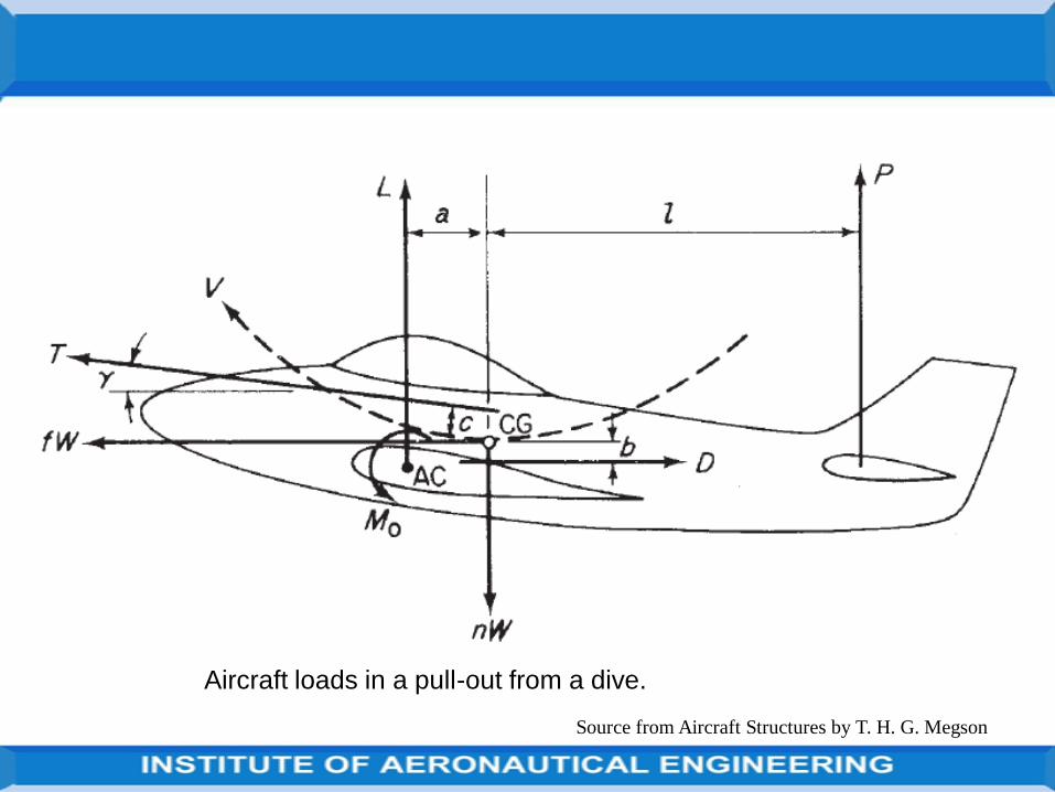
The loads acting on an aircraft in steady flight are shown in Fig. below, withthe following notation: L is the lift acting at the aerodynamic centre of thewing. D is the aircraft drag.
M0 is the aerodynamic pitching moment of the aircraft less its horizontaltail. P is the horizontal tail load acting at the aerodynamic centre of thetail, usually taken to be at approximately one-third of the tailplane chord.
W is the aircraft weight acting at its CG. T is the engine thrust, assumedhere to act parallel to the direction of flight in order to simplify calculation.
Source from Aircraft Structures by T. H. G. Megson
Level flight
Source from Aircraft Structures by T. H. G. Megson
Aircraft loads in level flight.
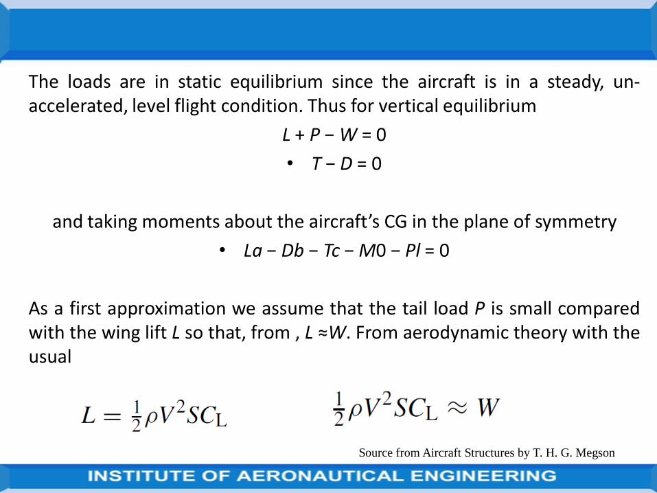
The loads are in static equilibrium since the aircraft is in a steady, un-accelerated, level flight condition. Thus for vertical equilibrium
L + P − W = 0
• T − D = 0
and taking moments about the aircraft’s CG in the plane of symmetry
• La − Db − Tc − M0 − Pl = 0
As a first approximation we assume that the tail load P is small comparedwith the wing lift L so that, from , L ≈W. From aerodynamic theory with theusual
Source from Aircraft Structures by T. H. G. Megson
Source from Aircraft Structures by T. H. G. Megson
Aircraft loads in a pull-out from a dive.
Source from Aircraft Structures by T. H. G. Megson
Monocoque and semi monocoque structuresThe basic functions of an aircraft’s structure are to transmit and resist theapplied loads;
to provide an aerodynamic shape and to protect passengers, payload,systems, etc. from the environmental conditions encountered in flight.
These requirements, in most aircraft, result in thin shell structures where theouter surface or skin of the shell is usually supported by longitudinalstiffening members and transverse frames to enable it to resist bending,compressive and torsional loads without buckling.
Such structures are known as semi-monocoque,
while thin shells which rely entirely on their skins for their capacity to resistloads are referred to as monocoque.

Source from Aircraft Structures by T. H. G. Megson
monocoque structures

Source from Aircraft Structures by T. H. G. Megson
monocoque structures

Source from Aircraft Structures by T. H. G. Megson
monocoque structures

Source from Aircraft Structures by T. H. G. Megson
semi monocoque structures

Source from Aircraft Structures by T. H. G. Megson
semi monocoque structures
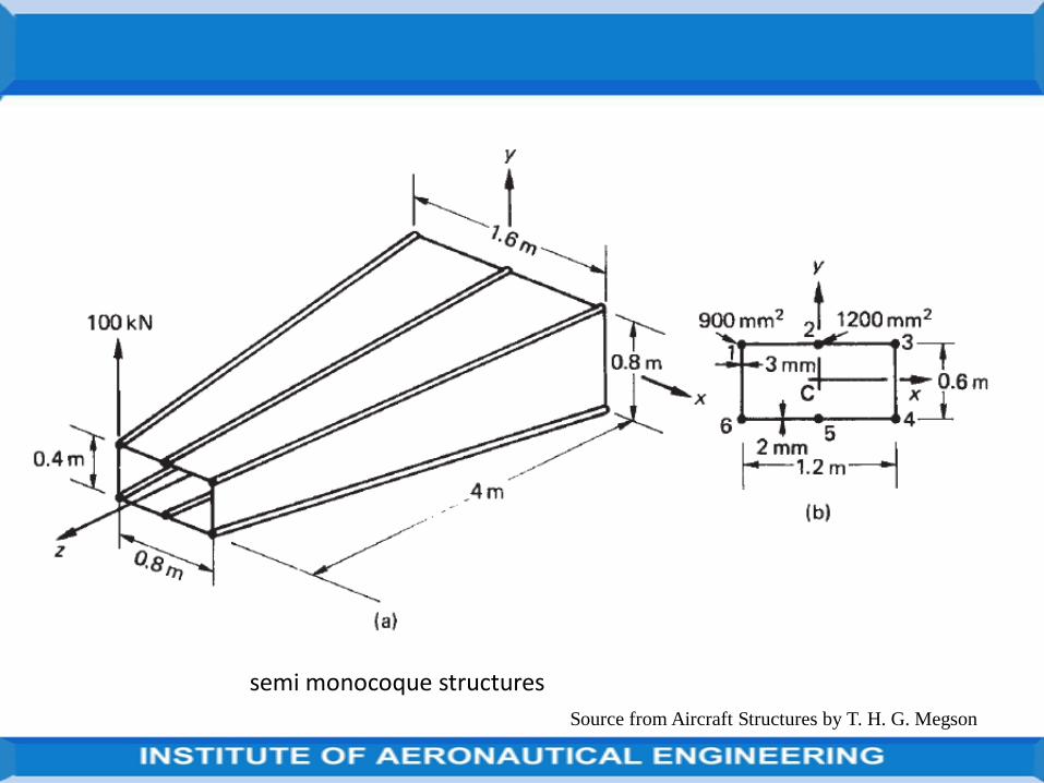
Source from Aircraft Structures by T. H. G. Megson
semi monocoque structures
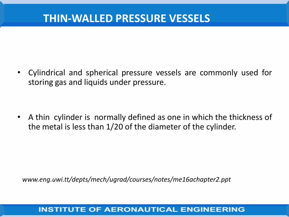
THIN-WALLED PRESSURE VESSELS
• Cylindrical and spherical pressure vessels are commonly used forstoring gas and liquids under pressure.
• A thin cylinder is normally defined as one in which the thickness ofthe metal is less than 1/20 of the diameter of the cylinder.
www.eng.uwi.tt/depts/mech/ugrad/courses/notes/me16achapter2.ppt

THIN-WALLED PRESSURE VESSELS CONT…
In thin cylinders, it can be assumed that the variation of stress within themetal is negligible, and that the mean diameter
Dm is approximately equal to the internal diameter, D.
At mid-length, the walls are subjected to hoop or circumferential stress,and a longitudinal stress, .
www.eng.uwi.tt/depts/mech/ugrad/courses/notes/me16achapter2.ppt
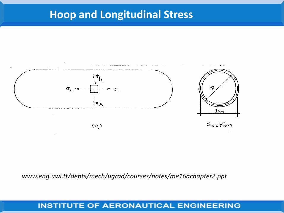
Hoop and Longitudinal Stress
www.eng.uwi.tt/depts/mech/ugrad/courses/notes/me16achapter2.ppt
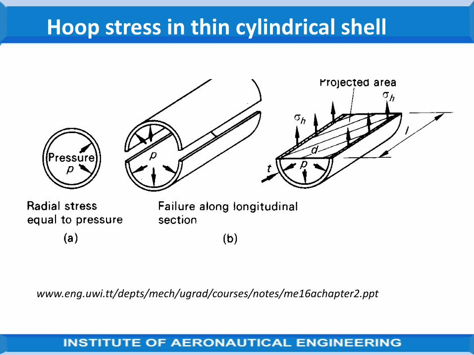
Hoop stress in thin cylindrical shell
www.eng.uwi.tt/depts/mech/ugrad/courses/notes/me16achapter2.ppt
Hoop stress in thin cylindrical shell Contd.
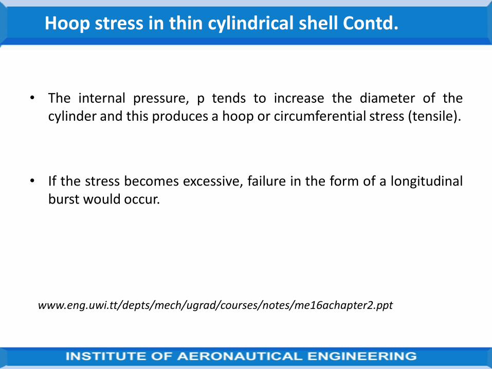
• The internal pressure, p tends to increase the diameter of thecylinder and this produces a hoop or circumferential stress (tensile).
• If the stress becomes excessive, failure in the form of a longitudinalburst would occur.
www.eng.uwi.tt/depts/mech/ugrad/courses/notes/me16achapter2.ppt

Hoop stress in thin cylindrical shell Concluded
Consider the half cylinder shown. Force due to internal pressure, p is balanced by the
force due to hoop stress, h .
i.e. hoop stress x area = pressure x projected area
h x 2 L t = P x d L
h = (P d) / 2 t
Where: d is the internal diameter of cylinder; t is the thickness of wall of cylinder.
www.eng.uwi.tt/depts/mech/ugrad/courses/notes/me16achapter2.ppt
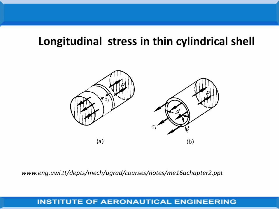
Longitudinal stress in thin cylindrical shell
www.eng.uwi.tt/depts/mech/ugrad/courses/notes/me16achapter2.ppt
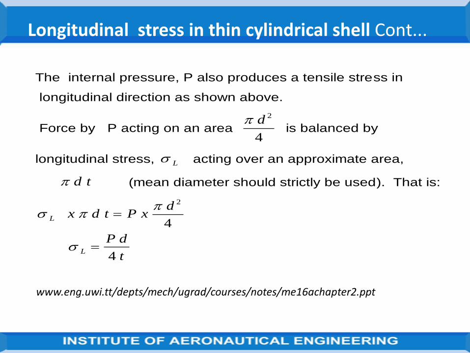
Longitudinal stress in thin cylindrical shell Cont...
The internal pressure, P also produces a tensile stress in
longitudinal direction as shown above.
Force by P acting on an area d 2
4 is balanced by
longitudinal stress, L acting over an approximate area,
d t (mean diameter should strictly be used). That is:
L
L
x d t P xd
P d
t
2
4
4
www.eng.uwi.tt/depts/mech/ugrad/courses/notes/me16achapter2.ppt

Note
Since hoop stress is twice longitudinal stress, the cylinder would failby tearing along a line parallel to the axis, rather than on a sectionperpendicular to the axis.
The equation for hoop stress is therefore used to determine thecylinder thickness.
Allowance is made for this by dividing the thickness obtained in hoopstress equation by efficiency (i.e. tearing and shearing efficiency) ofthe joint.
www.eng.uwi.tt/depts/mech/ugrad/courses/notes/me16achapter2.ppt

INTRODUCTION:
The thickness of the cylinder is large compared to that of thin cylinder.
In case of thick cylinders, the metal thickness ‘t’ is more than ‘d/20’,
where ‘d’ is the internal diameter of the cylinder.
Magnitude of radial stress (pr) is large and hence it cannot be neglected.
The circumferential stress is also not uniform across the cylinder wall.
The radial stress is compressive in nature and circumferential and
longitudinal stresses are tensile in nature.
Radial stress and circumferential stresses are computed by using ‘Lame’s
equations’.
www.engineeringduniya.com/slide_folder/First%20Year/.../MCYLINDERS.ppt

LAME’S EQUATIONS (Theory) :
www.engineeringduniya.com/slide_folder/First%20Year/.../MCYLINDERS.ppt
1. Plane sections of the cylinder normal to its axis remain plane and
normal even under pressure.
2. Longitudinal stress (σL) and longitudinal strain (εL) remain constant
throughout the thickness of the wall.
3. Since longitudinal stress (σL) and longitudinal strain (εL) are constant, it
follows that the difference in the magnitude of hoop stress and radial
stress (pr) at any point on the cylinder wall is a constant.
ASSUMPTIONS:

Let P1, P2 ,...., Pn be the forces acting at x1 , x2 ,......, xn from the left end on a simply supported beam of span L .Let u1 ,u2 ,..., un be the displacements at the loading P1, P2 ,...., Pn respectively as shown in figure.
Castigliono’s First Theorem
Source: https://www.slideshare.net/deepak_223/lecture-5-castiglionos-theorem

Assume that the material obeys Hooke’s law and invoking the principle of superposition, the work done by the external forces is given by
Work done by external forces is stored in structure as strain energy.
https://www.slideshare.net/deepak_223/lecture-5-castiglionos-theorem

u1 (deflection at point of application of P1) can be expressed as
In general
aij= flexibility coeff at i due to unit force applied at j.
Work done by external forces is stored in structure as strain energy.
https://www.slideshare.net/deepak_223/lecture-5-castiglionos-theorem

https://www.slideshare.net/deepak_223/lecture-5-castiglionos-theorem

Castigliano’s first theorem may be stated as the first partial derivative of thestrain energy of the structure with respect to any particular force gives thedisplacement of the point of application of that force in the direction of itsline of action.
https://www.slideshare.net/deepak_223/lecture-5-castiglionos-theorem
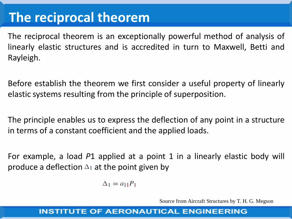
The reciprocal theorem is an exceptionally powerful method of analysis oflinearly elastic structures and is accredited in turn to Maxwell, Betti andRayleigh.
Before establish the theorem we first consider a useful property of linearlyelastic systems resulting from the principle of superposition.
The principle enables us to express the deflection of any point in a structurein terms of a constant coefficient and the applied loads.
For example, a load P1 applied at a point 1 in a linearly elastic body willproduce a deflection at the point given by
Source from Aircraft Structures by T. H. G. Megson
The reciprocal theorem

Source from Aircraft Structures by T. H. G. Megson
Linearly elastic body subjected to loads P1, P2, P3,…, Pn.

The influence or flexibility coefficient a11 is defined as the deflection at thepoint 1 in the direction of P1, produced by a unit load at the point 1 appliedin the direction of P1.
Clearly, if the body supports a system of loads such as those shown in Fig.each of the loads P1, P2, …,
Pn will contribute to the deflection at the point 1.
Thus, the corresponding deflection Δ1 at the point 1 is then
Source from Aircraft Structures by T. H. G. Megson

where a12 is the deflection at the point 1 in the direction of P1, produced bya unit load at the point 2 in the direction of the load P2 and so on.
The corresponding deflections at the points of application of the completesystem of loads are then
Source from Aircraft Structures by T. H. G. Megson

Source from Aircraft Structures by T. H. G. Megson
in matrix form

which may be written in shorthand matrix notation as
Source from Aircraft Structures by T. H. G. Megson
Suppose now that an elastic body is subjected to a gradually applied forceP1 at a point 1 and then, while P1 remains in position, a force P2 isgradually applied at another point 2.
The total strain energy U of the body is given by

The third term on the right-hand side of Eq. results from the additional workdone by P1 as it is displaced through a further distance a12 P2 by the actionof P2.
If we now remove the loads and apply P2 followed by P1 we have
Source from Aircraft Structures by T. H. G. Megson
By the principle of superposition the strain energy stored is
independent of the order in which the loads are applied. Hence

Thus in its simplest form the reciprocal theorem states that:
The deflection at a point 1 in a given direction due to a unit load at a point 2in a second direction is equal to the deflection at the point 2 in the seconddirection due to a unit load at the point 1 in the first direction.
In a similar manner, we derive the relationship between moments androtations, thus: The rotation at a point 1 due to a unit moment at a point 2 isequal to the rotation at the point 2 produced by a unit moment at the point1.
Finally, we have: The rotation at a point 1 due to a unit load at a point 2 isnumerically equal to the deflection at the point 2 in the direction of the unitload due to a unit moment at the point 1.
Source from Aircraft Structures by T. H. G. Megson

Discussed the dummy or fictitious load method of obtaining deflections ofstructures.
For a linearly elastic structure the method may be stream-lined as follows.
Consider the framework, in which we require, say, to find the verticaldeflection of the point C.
place a vertical dummy load Pf at C and write down the totalcomplementary energy of the framework, i.e.
Source from Aircraft Structures by T. H. G. Megson
Unit load method

For a stationary value of C
Source from Aircraft Structures by T. H. G. Megson
If instead of the arbitrary dummy load Pf we had placed a unit load at C, then the load in the ith linearly elastic member would be
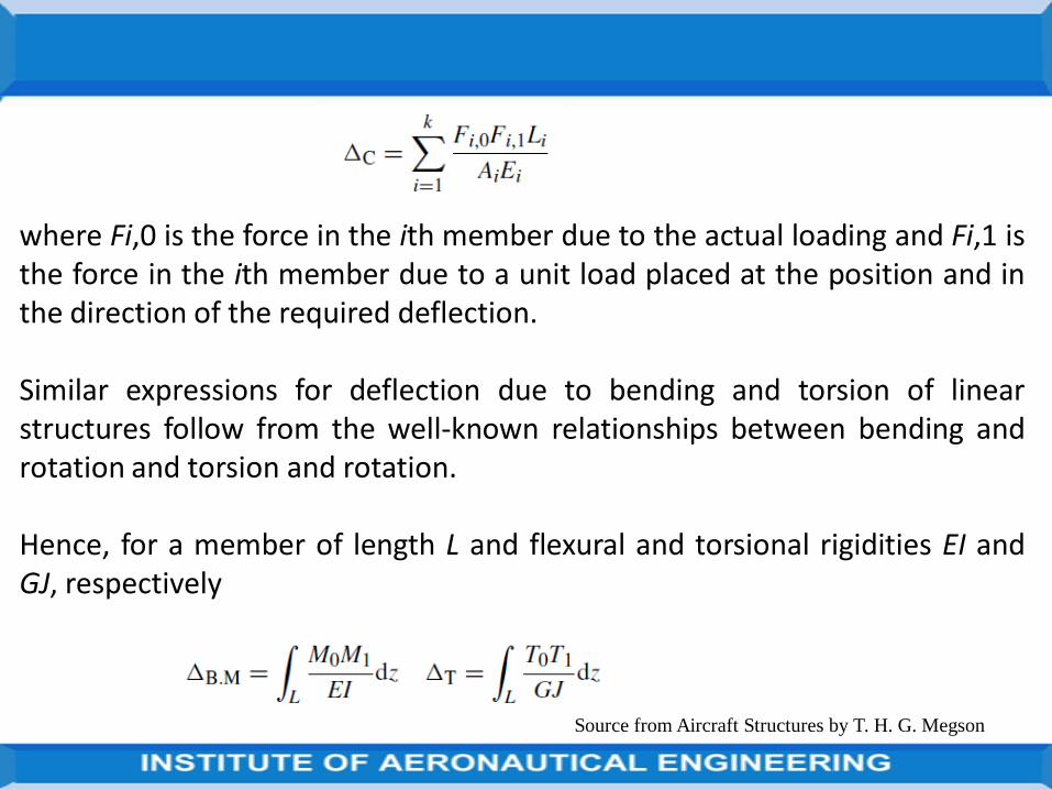
Source from Aircraft Structures by T. H. G. Megson
where Fi,0 is the force in the ith member due to the actual loading and Fi,1 isthe force in the ith member due to a unit load placed at the position and inthe direction of the required deflection.
Similar expressions for deflection due to bending and torsion of linearstructures follow from the well-known relationships between bending androtation and torsion and rotation.
Hence, for a member of length L and flexural and torsional rigidities EI andGJ, respectively
where M0 is the bending moment at any section produced by the actualloading and M1 is the bending moment at any section due to a unit loadapplied at the position and in the direction of the required deflection.
Similarly for torsion. Generally, shear deflections of slender beams areignored but may be calculated when required for particular cases.
Of greater interest in aircraft structures is the calculation of the deflectionsproduced by the large shear stresses experienced by thin-walled sections.
Source from Aircraft Structures by T. H. G. Megson
72
FE Modification of the Rayleigh-Ritz Method
In the Rayleigh-Ritz method
A single trial function is applied throughout the entire region
Trial functions of increasing complexity are required to model all but the
simplest problems
The FE approach
uses comparatively simple trial functions that are applied piece-wise to
parts of the region
These subsections of the region are then the finite elements
https://www.nafems.org/downloads/working_groups/etwg/intro4.ppt

73
Consider the problem of 1-D heat flow, the functional to be extremised is
where the integral over W corresponds to the length of the region and
Neumann boundary conditions are specified at one end, G,of the region
https://www.nafems.org/downloads/working_groups/etwg/intro4.ppt
2
r r
dk Q x dx k
dx
W

74
The length over which the solution is required, is divided up into finite
elements
In each element the value of f is found at certain points called nodes
Two nodes will mark the extremities of the element
Other nodes may occur inside the element
https://www.nafems.org/downloads/working_groups/etwg/intro4.ppt

75
Let the unknown temperatures at the nodes of the element e be
where n+1 is the number of nodes in each element.
e
i i i n
T
1
....
1
.
.
.
i
i
e
i n
https://www.nafems.org/downloads/working_groups/etwg/intro4.ppt

76
The temperature at any other position in the element is represented in
terms of the nodal values {f}e and shape functions associated with each
node
where Nb is the shape function associated with the node b and b=i
... i+n and [N] is the corresponding row matrix.
N N
e
https://www.nafems.org/downloads/working_groups/etwg/intro4.ppt

77
Let us write the trial function over the entire region in the form
where the summation is over all the nodes in W.
N g
https://www.nafems.org/downloads/working_groups/etwg/intro4.ppt

78
The global shape functions have been used to take into account
the contribution from fa to f over the entire region W
The global shape functions over much of W will be zero
For interior nodes of an element will be non-zero only within
that element
End nodes of an element will have non-zero values over the two
elements sharing the node.
gN
gN
https://www.nafems.org/downloads/working_groups/etwg/intro4.ppt
79
Example :
is non-zero only in elements e and e+1.
will be non-zero only in element e.
Ni n
g
N N Ni
g
i
g
i n
g
1 2 1, , ....
https://www.nafems.org/downloads/working_groups/etwg/intro4.ppt

80
Neglecting for the moment, consideration of the first and last elements of the
region
Write the Rayleigh-Ritz statement in which the nodal values are the adjustable
parameters.
Consider the nodes i...i+n belonging to element e
https://www.nafems.org/downloads/working_groups/etwg/intro4.ppt

81
where for example element e stands for
over the element e
i n i n element e element e
1
0
element e
i i n0 1 1: .....
i i element e element e
1
0
kd
dxQ x dx
2
https://www.nafems.org/downloads/working_groups/etwg/intro4.ppt

82
Since
i element e
1
i element e
is an expression involving {e-1
involves {e
and there is no relationship between {e-1 and {e ,both
expressions must be equal to zero
https://www.nafems.org/downloads/working_groups/etwg/intro4.ppt

83
Let us focus on the terms containing an integral over the element e
Drop the superscript g on the shape functions
Suppose that the element extends from x=xe to x=xe+h
No loss in generality is incurred if we
Shift the origin to x=xe
Take the element to extend rather from 0 to h
https://www.nafems.org/downloads/working_groups/etwg/intro4.ppthttps://www.nafems.org/downloads/working_groups/etwg/intro4.ppt

84
The function can be written as,
k d
dxN Q x N dx
e e
k
2
2
0
= i ...i+nwhere
Note that
x x
NdN
dx
dN
dx
dN
dx
e i i
i
i n
e
, ..... .1
https://www.nafems.org/downloads/working_groups/etwg/intro4.ppt

85
Also, noting
Since
Hence
x x x
dN
dx
dN
dx
e
2
2 2
x
dN
dx
e
x
dN
dx
https://www.nafems.org/downloads/working_groups/etwg/intro4.ppt

86
So, differentiating under the integral sign, we have
kdN
dx
dN
dxdx Q x N dx
e
hh
00
Hence
kdN
dx
dN
dxQ x N dx
e
h
0
0
https://www.nafems.org/downloads/working_groups/etwg/intro4.ppt

87
This equation is one in the set of n+1 simultaneous equations obtained by letting
run through the values i...i+n :
k k k
k k
k
F
F
i i i i i i n
i i i i n
i n i n
i
i n
i
e
i n
e
, , ,
, ,
,
. .
. .
. . .
. .
1
1 1 1
https://www.nafems.org/downloads/working_groups/etwg/intro4.ppt

88
where
and
In the end elements, where Neumann boundary conditions may have to be
considered, there is an additional term
where Nr is the value of N on the boundary G
F Q x N dxe
h
0
k kN
x
N
xdx
t
0
k k N
r r r r
,
https://www.nafems.org/downloads/working_groups/etwg/intro4.ppt

89
If there are two 2-noded elements, labelled m and n, with nodes i, i+1 and
i+2, assembly of the element matrices is as before. Then
for the first element m
and similarly for element n
11, 1 1, 2 1
22, 1 2, 2 2
n n nii i i i i
n n nii i i i i
k k F
k k F
, , 1
11, 1, 1 1
m m mii i i i i
m m mii i i i i
k k F
k k F

90
By combining these two matrix equations
The global assembly matrix is built up in this way
The boundary conditions on the extreme elements are inserted
The set of equations is solved for the unknown values of
, , 1
1, 1, 1 1, 1 1, 2 1 1 1
2 22, 1 2, 2
0
0
m m mi i i i i i
m m n n m n
i i i i i i i i i i i
nn ni ii i i i
k k F
k k k k F F
Fk k
https://www.nafems.org/downloads/working_groups/etwg/intro4.ppt
In the spring–mass system shown in its unstrained position in Fig. normallydefine the potential energy of the mass as the product of its weight, Mg,and its height, h, above some arbitrarily fixed datum.
In other words it possesses energy by virtue of its position. After deflectionto an equilibrium state the mass has lost an amount of potential energyequal to Mgy.
Thus we may associate deflection with a loss of potential energy.Alternatively, we may argue that the gravitational force acting on the massdoes work during its displacement, resulting in a loss of energy.
Source from Aircraft Structures by T. H. G. Megson
Total potential energy Method
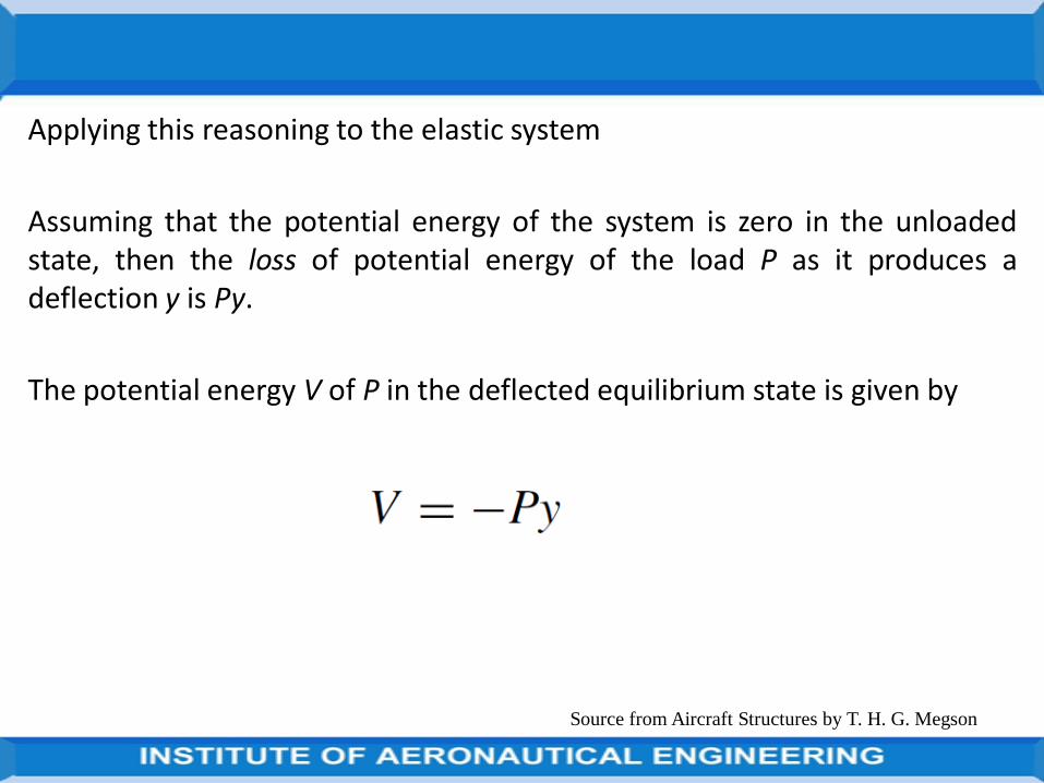
Applying this reasoning to the elastic system
Assuming that the potential energy of the system is zero in the unloadedstate, then the loss of potential energy of the load P as it produces adeflection y is Py.
The potential energy V of P in the deflected equilibrium state is given by
Source from Aircraft Structures by T. H. G. Megson

Source from Aircraft Structures by T. H. G. Megson
(a) Potential energy of a spring–mass system; (b) loss in potential energy due
to change in position.

We now define the total potential energy (TPE) of a system in its deflectedequilibrium state as the sum of its internal or strain energy and the potentialenergy of the applied external forces.
for the single member–force configuration of Fig. (a)
Source from Aircraft Structures by T. H. G. Megson
For a general system consisting of loads P1, P2, …, Pn producingcorresponding displacements 1, 2, …, n the potential energy of all the loadsis

Source from Aircraft Structures by T. H. G. Megson
and the total potential energy of the system is given by

An alternative approach to the solution of statically indeterminate beamsand frames is to release the structure
i.e. remove redundant members or supports, until the structure becomesstatically determinate.
The displacement of some point in the released structure is thendetermined by the unit load method.
The actual loads on the structure are removed and unknown forces appliedto the points where the structure has been released;
the displacement at the point produced by these unknown forces must,from compatibility,
Source from Aircraft Structures by T. H. G. Megson
Flexibility method

be the same as that in the released structure. The unknown forces are thenobtained; this approach is known as the flexibility method.
Source from Aircraft Structures by T. H. G. Megson

UNIT II
THIN PLATE THEORY, STRUCTURAL INSTABILITY

The thin rectangular plate of Fig. is subjected to pure bending moments ofintensity Mx and My per unit length uniformly distributed along its edges.
The former bending moment is applied along the edges parallel to the yaxis, the latter along the edges parallel to the x axis.
Assume that these bending moments are positive when they producecompression at the upper surface of the plate and tension at the lower.
If we further assume that the displacement of the plate in a directionparallel to the z axis is small compared with its thickness t and that sections
Source from Aircraft Structures by T. H. G. Megson
Pure bending of thin plates

which are plane before bending remain plane after bending, then, as in thecase of simple beam theory, the middle plane of the plate does not deformduring the bending and is therefore a neutral plane.
Take the neutral plane as the reference plane for our system of axes.
Consider an element of the plate of side δxδy and having a depth equal tothe thickness t of the plate as shown in Fig.
Suppose that the radii of curvature of the neutral plane n are ρx and ρy inthe xz and yz planes respectively Fig.
Source from Aircraft Structures by T. H. G. Megson

Positive curvature of the plate corresponds to the positive bendingmoments which produce displacements in the positive direction of the z ordownward axis.
Again, as in simple beam theory, the direct strains εx and εy correspondingto direct stresses σx and σy of an elemental lamina of thickness δz adistance z below the neutral plane are given by
Source from Aircraft Structures by T. H. G. Megson

Source from Aircraft Structures by T. H. G. Megson

Source from Aircraft Structures by T. H. G. Megson
(a) Direct stress on lamina of plate element; (b) radii of curvature of neutral plane.

Source from Aircraft Structures by T. H. G. Megson

D is known as the flexural rigidity of the plate.
If w is the deflection of any point on the plate in the z direction, then wemay relate w to the curvature of the plate in the same manner as the well-known expression for beam curvature.
Hence
The negative signs resulting from the fact that the centres of curvatureoccur above the plate in which region z is negative.
Source from Aircraft Structures by T. H. G. Megson

Source from Aircraft Structures by T. H. G. Megson
Anticlastic bending

The deflected shape of the plate provided that Mx and My are known.
If either Mx or My is zero then
The plate has curvatures of opposite signs. The case of My =0 is illustrated inFig. A surface possessing two curvatures of opposite sign is known as ananticlastic surface, as opposed to a synclastic surface which has curvaturesof the same sign. Further, if Mx =My =M
Source from Aircraft Structures by T. H. G. Megson

Source from Aircraft Structures by T. H. G. Megson
Therefore, the deformed shape of the plate is spherical and of curvature

Bending moments applied to the plate will not be in planes perpendicular toits edges.
Such bending moments, however, may be resolved in the normal mannerinto tangential and perpendicular components, as shown in Fig.
The perpendicular components are seen to be Mx and My as before, whilethe tangential components Mxy and Myx (again these are moments per unitlength) produce twisting of the plate about axes parallel to the x and y axes.
The system of suffixes and the sign convention for these twisting momentsmust be clearly understood to avoid confusion.
Source from Aircraft Structures by T. H. G. Megson
Plates subjected to bending and twisting

Mxy is a twisting moment intensity in a vertical x plane parallel to the y axis,while Myx is a twisting moment intensity in a vertical y plane parallel to thex axis.
Note that the first suffix gives the direction of the axis of the twistingmoment.
Also define positive twisting moments as being clockwise when viewedalong their axes in directions parallel to the positive directions of thecorresponding x or y axis.
All moment intensities are positive.
Source from Aircraft Structures by T. H. G. Megson

Source from Aircraft Structures by T. H. G. Megson
Plate subjected to bending and twisting

Source from Aircraft Structures by T. H. G. Megson
(a) Plate subjected to bending and twisting; (b) tangential and normal moments on
an arbitrary plane

Since the twisting moments are tangential moments or torques they areresisted by a system of horizontal shear stresses τxy, as shown in Fig.
From a consideration of complementary shear stresses. Mxy=−Myx, so thatwe may represent a general moment application to the plate in terms ofMx, My and Mxy as shown in Fig.
These moments produce tangential and normal moments, Mt and Mn, onan arbitrarily chosen diagonal plane FD.
Express these moment intensities in terms of Mx, My and Mxy. Thus, forequilibrium of the triangular element ABC of Fig. in a plane perpendicular toAC
Source from Aircraft Structures by T. H. G. Megson

Source from Aircraft Structures by T. H. G. Megson
Similarly for equilibrium in a plane parallel to CA

Source from Aircraft Structures by T. H. G. Megson
Complementary shear stresses due to twisting moments Mxy.

Source from Aircraft Structures by T. H. G. Megson

Source from Aircraft Structures by T. H. G. Megson
Determination of shear strain γxy.

Source from Aircraft Structures by T. H. G. Megson

Source from Aircraft Structures by T. H. G. Megson
Multiplying the numerator and denominator of this equation by the factor (1−ν) yields
Above eqs. relate the bending and twisting moments to the platedeflection and are analogous to the bending moment-curvaturerelationship for a simple beam.

The relationships between bending and twisting moments and platedeflection are now employed in establishing the general differentialequation for the solution of a thin rectangular plate, supporting adistributed transverse load of intensity q per unit area .
Source from Aircraft Structures by T. H. G. Megson
Plates subjected to a distributed transverse load
Plate supporting a distributed transverse load.

Source from Aircraft Structures by T. H. G. Megson
Plate element subjected to bending, twisting and transverse loads.

Source from Aircraft Structures by T. H. G. Megson
shear forces Qxδy and Qyδx are assumed to act through the centroid of the faces of the element. From the previous sections
For equilibrium of the element parallel to Oz and assuming that the weight of the
plate is included in q

Source from Aircraft Structures by T. H. G. Megson

Source from Aircraft Structures by T. H. G. Megson

Source from Aircraft Structures by T. H. G. Megson
Direct and shear stresses are then calculated from the relevant expressions relatingthem to Mx, My, Mxy, Qx and Qy.

So far our discussion has been limited to small deflections of thin platesproduced by different forms of transverse loading.
In these cases we assumed that the middle or neutral plane of the plateremained unstressed.
Additional in-plane tensile, compressive or shear loads will produce stressesin the middle plane, and these, if of sufficient magnitude, will affect thebending of the plate.
Where the in-plane stresses are small compared with the critical bucklingstresses it is sufficient to consider the two systems separately; the totalstresses are then obtained by superposition.
Source from Aircraft Structures by T. H. G. Megson
Combined bending and in-plane loading of a thin rectangular plate

Source from Aircraft Structures by T. H. G. MegsonIn-plane forces on plate element

On the other hand, if the in-plane stresses are not small then their effect onthe bending of the plate must be considered.
Source from Aircraft Structures by T. H. G. Megson
For small deflections ∂w/∂x and (∂w/∂x)+(∂2w/∂x2)δx are small and thecosines of these angles are therefore approximately equal to one. Theequilibrium equation thus simplifies to

Source from Aircraft Structures by T. H. G. Megson
Component of shear loads in the z direction.

Source from Aircraft Structures by T. H. G. Megson
Similarly for equilibrium in the y direction we have
neglecting terms of a lower order. Similarly, the contribution of Nyx is

Source from Aircraft Structures by T. H. G. Megson
The total force in the z direction is found from the summation of these expressions
and is

Source from Aircraft Structures by T. H. G. Megson
in which Nyx is equal to and is replaced by Nxy. Reduce this expression to

Source from Aircraft Structures by T. H. G. Megson
Since the in-plane forces do not produce moments along the edges of theelement then Eqs. remain unaffected.
Modified simply by the addition of the above vertical component of the in-plane loads to qδxδy.
Therefore, the governing differential equation for a thin plate supportingtransverse and in-plane loads is

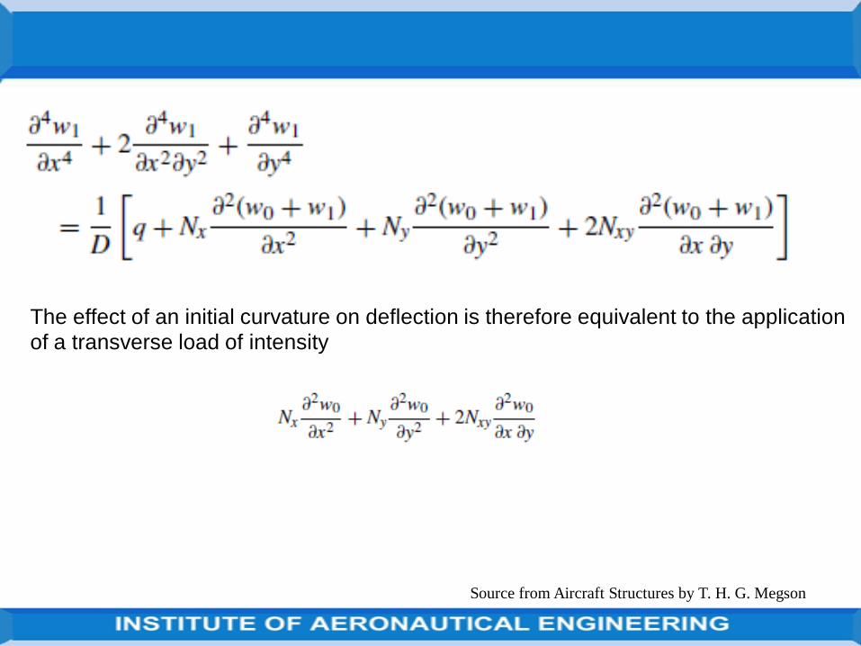
Suppose that a thin plate has an initial curvature so that the deflection ofany point in its middle plane is w0.
Assume that w0 is small compared with the thickness of the plate. Theapplication of transverse and in-plane loads will cause the plate to deflect afurther amount w1 so that the total deflection is then w=w0 +w1.
The derivation of Eq. the left-hand side was obtained from expressions forbending moments which themselves depend on the change of curvature.
Use the deflection w1 on the left-hand side, not w. The effect on bending ofthe in-plane forces depends on the total deflection w
Source from Aircraft Structures by T. H. G. Megson
Thin plates having a small initial curvature
Source from Aircraft Structures by T. H. G. Megson
The effect of an initial curvature on deflection is therefore equivalent to the application
of a transverse load of intensity
Source from Aircraft Structures by T. H. G. Megson
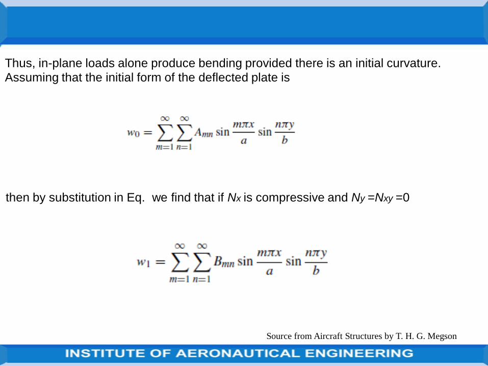
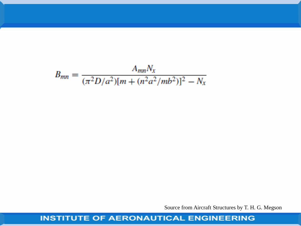
Thus, in-plane loads alone produce bending provided there is an initial curvature.
Assuming that the initial form of the deflected plate is
then by substitution in Eq. we find that if Nx is compressive and Ny =Nxy =0
Source from Aircraft Structures by T. H. G. Megson
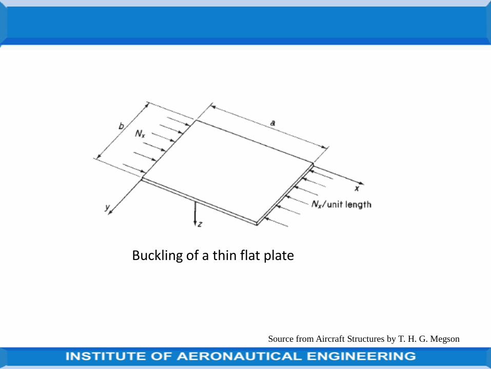
A thin plate may buckle in a variety of modes depending upon itsdimensions, the loading and the method of support.
Buckling loads are much lower than those likely to cause failure in thematerial of the plate.
The simplest form of buckling arises when compressive loads are applied tosimply supported opposite edges and the unloaded edges are free, asshown in Fig. A thin plate in this configuration behaves in exactly the sameway as a pin-ended column so that the critical load is that predicted by theEuler theory.
Once this critical load is reached the plate is incapable of supporting anyfurther load.
Source from Aircraft Structures by T. H. G. Megson
The unloaded edges are supported against displacement out of the xyplane.
Buckling, for such plates, takes the form of a bulging displacement of thecentral region of the plate while the parts adjacent to the supported edgesremain straight.
These parts enable the plate to resist higher loads; an important factor inaircraft design.
Here not concerned with this post-buckling behaviour, but rather with theprediction of the critical load which causes the initial bulging of the centralarea of the plate.
Source from Aircraft Structures by T. H. G. Megson
Source from Aircraft Structures by T. H. G. Megson
Buckling of a thin flat plate
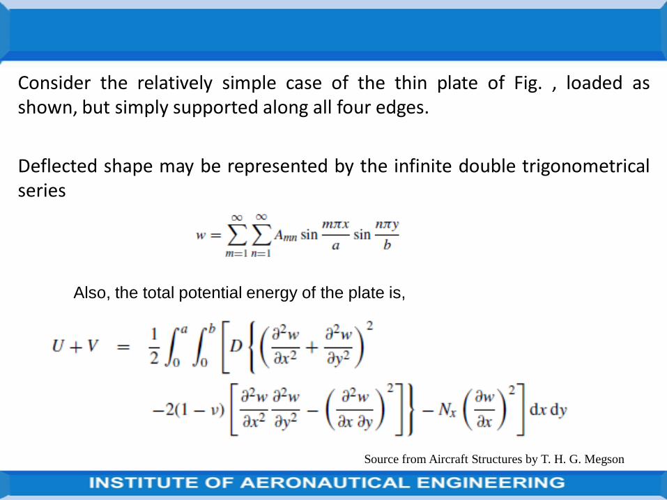
Consider the relatively simple case of the thin plate of Fig. , loaded asshown, but simply supported along all four edges.
Deflected shape may be represented by the infinite double trigonometricalseries
Source from Aircraft Structures by T. H. G. Megson
Also, the total potential energy of the plate is,
Source from Aircraft Structures by T. H. G. Megson
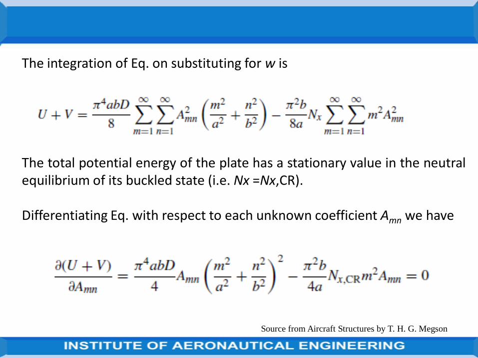
The integration of Eq. on substituting for w is
The total potential energy of the plate has a stationary value in the neutralequilibrium of its buckled state (i.e. Nx =Nx,CR).
Differentiating Eq. with respect to each unknown coefficient Amn we have
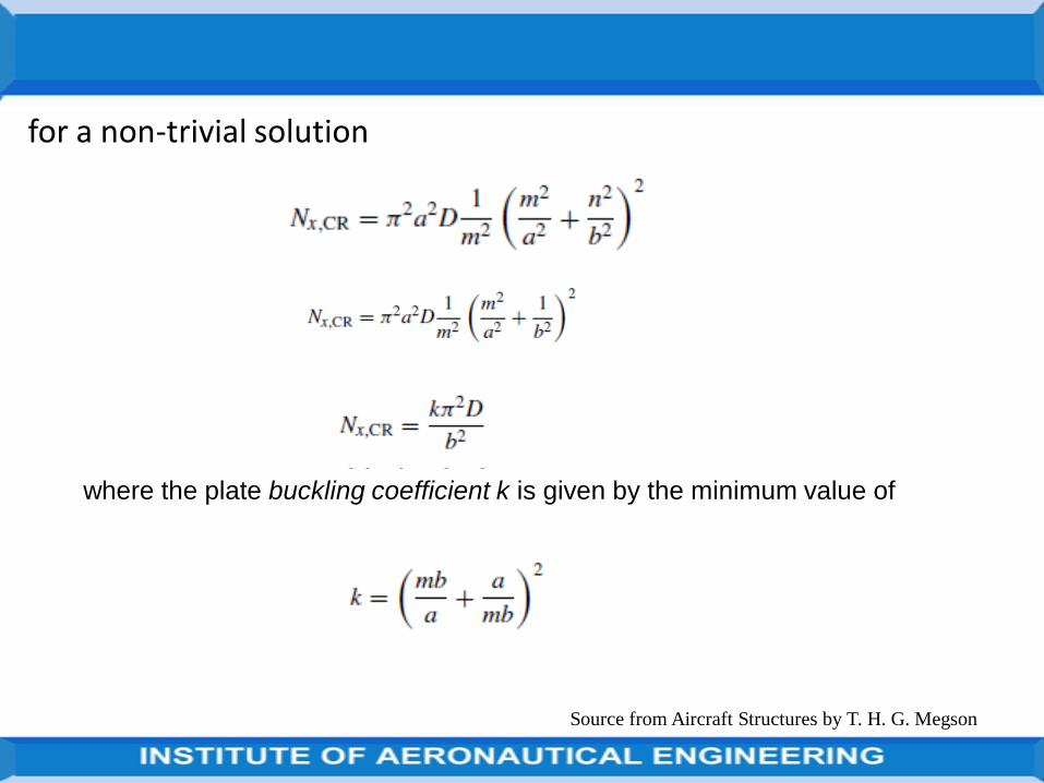
for a non-trivial solution
Source from Aircraft Structures by T. H. G. Megson
where the plate buckling coefficient k is given by the minimum value of
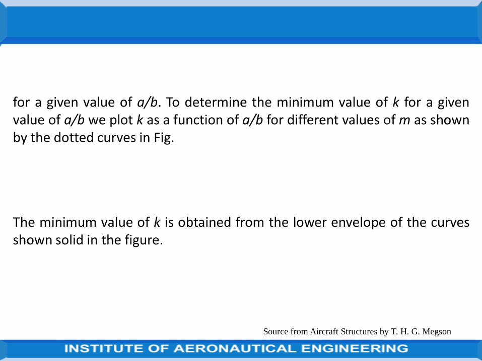
for a given value of a/b. To determine the minimum value of k for a givenvalue of a/b we plot k as a function of a/b for different values of m as shownby the dotted curves in Fig.
The minimum value of k is obtained from the lower envelope of the curvesshown solid in the figure.
Source from Aircraft Structures by T. H. G. Megson
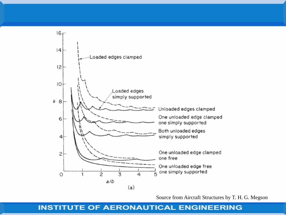
Source from Aircraft Structures by T. H. G. Megson
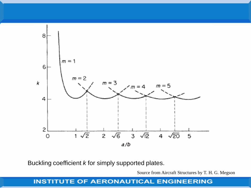
Buckling coefficient k for simply supported plates.
It can be seen that m varies with the ratio a/b and that k and the bucklingload are a minimum when k =4 at values of a/b=1, 2, 3, . . . .As a/b becomeslarge k approaches 4 so that long narrow plates tend to buckle into a seriesof squares.
The transition from one buckling mode to the next may be found byequating values of k for the m and m+1 curves. Hence
Source from Aircraft Structures by T. H. G. Megson
Substituting m=1, we have a/b= √2=1.414, and for m=2, a/b=√6=2.45 and
so on.
For a given value of a/b the critical stress, σCR =Nx,CR/t, is found from Eqs
Source from Aircraft Structures by T. H. G. Megson
For plates having small values of b/t the critical stress may exceed the elasticlimit of the material of the plate.
In such a situation, Eq.
is no longer applicable since, as we saw in the case of columns, E becomesdependent on stress as does Poisson’s ratio ν.
These effects are usually included in a plasticity correction factor η so thatabove Eq. becomes
Source from Aircraft Structures by T. H. G. Megson
Inelastic buckling of plates
Source from Aircraft Structures by T. H. G. Megson
Source from Aircraft Structures by T. H. G. Megson
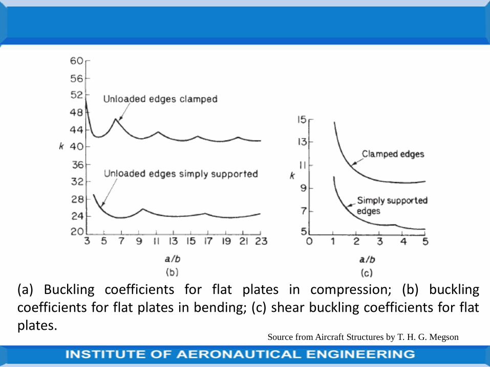
(a) Buckling coefficients for flat plates in compression; (b) bucklingcoefficients for flat plates in bending; (c) shear buckling coefficients for flatplates.

where E and ν are elastic values of Young’s modulus and Poisson’s ratio.
In the linearly elastic region η=1, which means that Eq. may be applied at allstress levels.
Below eq. will giving good agreement with experiment is
where Et and Es are the tangent modulus and secant modulus (stress/strain)of the plate in the inelastic region and νe and νp are Poisson’s ratio in theelastic and inelastic ranges.
Source from Aircraft Structures by T. H. G. Megson

The critical load for a column may be determined experimentally, withoutactually causing the column to buckle, by means of the Southwell plot.
The critical load for an actual, rectangular, thin plate is found in a similarmanner.
The displacement of an initially curved plate from the zero load position wasfound
Source from Aircraft Structures by T. H. G. Megson
Experimental determination of critical load for a flat plate

Source from Aircraft Structures by T. H. G. Megson
where
The coefficients Bmn increase with an increase of compressive load intensityNx.
It follows that when Nx approaches the critical value, Nx,CR, the term in theseries corresponding to the buckled shape of the plate becomes the mostsignificant.
For a square plate n=1 and m=1 give a minimum value of critical load so thatat the centre of the plate

Source from Aircraft Structures by T. H. G. Megson
or, rearranging
A graph of w1 plotted against w1 / Nx will have a slope, in the region of the
critical load, equal to Nx,CR.

Distinguished in the primary and secondary (or local) instability.
The latter form of buckling usually occurs in the flanges and webs of thin-walled columns having an effective slenderness ratio, le/r <20.
For le/r >80 this type of column is susceptible to primary instability.
In the intermediate range of le/r between 20 and 80, buckling occurs by acombination of both primary and secondary modes.
Source from Aircraft Structures by T. H. G. Megson
Local instability

Thin-walled columns are encountered in aircraft structures in the shape oflongitudinal stiffeners, which are normally fabricated by extrusion processesor by forming from a flat sheet.
A variety of cross-sections are employed although each is usually composedof flat plate elements arranged to form angle, channel, Z- or ‘top hat’sections, as shown in Fig. below.
The plate elements fall into two distinct categories: flanges which have afree unloaded edge and webs which are supported by the adjacent plateelements on both unloaded edges.
Source from Aircraft Structures by T. H. G. Megson

Source from Aircraft Structures by T. H. G. Megson
(a) Extruded angle; (b) formed channel; (c) extruded Z; (d) formed ‘top hat’.

Source from Aircraft Structures by T. H. G. Megson
and an appropriate value of k.
For example,
K for a cruciform section column is obtained from Fig(a) . Below for a platewhich is simply supported on three sides with one edge free and has a/b>3.
Hence k =0.43 and if the section buckles elastically then η=1
Values of local critical stress for columns possessing these types of sectionmay be found using Eq.

Source from Aircraft Structures by T. H. G. Megson

Source from Aircraft Structures by T. H. G. Megson
It must be appreciated that the calculation of local buckling stresses isgenerally complicated with no particular method gaining universalacceptance, much of the information available being experimental.

UNIT IIIBENDING, SHEAR AND TORSION OF
THIN WALLED BEAMS

General stress
The equations of equilibrium and expressions for strain which are necessaryfor the analysis of open section beams supporting shear loads and closedsection beams carrying shear and torsional loads.
The analysis of open section beams subjected to torsion requires a differentapproach
The relationships are established from first principles for the particular caseof thin-walled sections
Source from Aircraft Structures by T. H. G. Megson

AnalysisAssumed that axial constraint effects are negligible,
Shear stresses normal to the beam surface may be neglected since they arezero at each surface and the wall is thin,
Direct and shear stresses on planes normal to the beam surface are constantacross the thickness,
Finally, the beam is of uniform section so that the thickness may vary withdistance around each section but is constant along the beam.
In addition, ignore squares and higher powers of the thickness t in thecalculation of section properties
Source from Aircraft Structures by T. H. G. Megson

The parameter s in the analysis is distance measured around the cross-section from some convenient origin.
An element δs×δz×t of the beam wall is maintained in equilibrium by a system of direct and shear stresses as shown in Fig. below.
(a) General stress system on element of a closed or open section beam;(b) (b) direct stress and shear flow system on the element.
Source from Aircraft Structures by T. H. G. Megson

The direct stress σz is produced by bending moments or by the bendingaction of shear loads while the shear stresses are due to shear and/ortorsion of a closed section beam or shear of an open section beam.
The hoop stress σs is usually zero but may be caused, in closed sectionbeams, by internal pressure.
Specified that t may vary with s, this variation is small for most thin-walledstructures
so that we may reasonably make the approximation that t is constant overthe length δs. Also, deduce that τzs =τsz =τ say.
However, we shall find it convenient to work in terms of shear flow q, i.e.shear force per unit length rather than in terms of shear stress. q = τt
Source from Aircraft Structures by T. H. G. Megson

For equilibrium of the element in the z direction and neglecting body forces
The direct stresses σz and σs produce direct strains εz and εs, while theshear stress τ induces a shear strain γ(=γzs =γsz).
Let vt is a tangential displacement in the xy plane and is taken to be positivein the direction of increasing s; vn is a normal displacement in the xy planeand is positive outwards; and w is an axial displacement.εz = ∂w/∂z εs = *(∂vt/∂s) + (vn/r)]
Source from Aircraft Structures by T. H. G. Megson

The shear strain γ is found in terms of the displacements w and vt by considering the shear distortion of an element δs×δz of the beam wall. The shear strain is given by
γ = φ1 + φ2
or, in the limit as both δs and δz tend to zero
γ = ∂w/∂s + ∂vt/∂z
Source from Aircraft Structures by T. H. G. Megson

Assume that during any displacement the shape of the beam cross-sectionis maintained by a system of closely spaced diaphragms which are rigid intheir own plane but are perfectly flexible normal to their own plane (CSRDassumption).
There is, therefore, no resistance to axial displacement w and the cross-section moves as a rigid body in its own plane, the displacement of anypoint being completely specified by translations u and v and a rotation θ .
Source from Aircraft Structures by T. H. G. Megson
The origin O of the axes in Fig. has been chosen arbitrarily and the axessuffer displacements u, v and θ. These displacements, in a loading casesuch as pure torsion, are equivalent to a pure rotation about some pointR(xR,yR) in the cross-section where R is the centre of twist.


Source from Aircraft Structures by T. H. G. Megson

Shear of open section beams
The open section beam of arbitrary section shown in Fig. supports shear
loads Sx and Sy such that there is no twisting of the beam cross-section.
For this condition to be valid the shear loads must both pass through a
particular point in the cross-section known as the shear centre.
Since there are no hoop stresses in the beam the shear flows and direct
stresses acting on an element of the beam wall are related by
Source from Aircraft Structures by T. H. G. Megson

Source from Aircraft Structures by T. H. G. Megson
shear loads Sx and Sy such that thereis no twisting of the beam cross-section. For this condition to be validthe shear loads must both passthrough a particular point in the cross-section known as the shear centre.Since there are no hoop stresses inthe beam the shear flows and directstresses actingon an element of the beam wall arerelated by

Substituting for ∂σz/∂z
Integrating above equation with respect to s from some origin for s to any point around the cross-section, we obtain
If the origin for s is taken at the open edge of the cross-section, then q=0 when s=0 and Eq.above becomes
Source from Aircraft Structures by T. H. G. Megson

For a section having either Cx or Cy as an axis of symmetry Ixy =0 and
Eq. above reduces to
Source from Aircraft Structures by T. H. G. Megson

Shear of closed section beams
The solution for a shear loaded closed section beam follows a similar
pattern to that described in Sectio for an open section beam but with two
important differences.
First, the shear loads may be applied through points in the cross-section
other than the shear centre so that torsional as well as shear effects are
included.
Source from Aircraft Structures by T. H. G. Megson

This is possible since, as we shall see, shear stresses produced by torsion inclosed section beams have exactly the same form as shear stressesproduced by shear, unlike shear stresses due to shear and torsion in opensection beams.
Secondly, it is generally not possible to choose an origin for s at which thevalue of shear flow is known.
Let us suppose that we choose an origin for s where the shear flow has theunknown value qs,0.
Source from Aircraft Structures by T. H. G. Megson

This fact indicates a method of solution for a shear loaded closed section
beam. Representing this ‘open’ section or ‘basic’ shear flow by qb,
Source from Aircraft Structures by T. H. G. Megson


The value of shear flow at the cut (s = 0) is then found by equating
applied and internal moments taken about some convenient moment
centre.
Source from Aircraft Structures by T. H. G. Megson

where A is the area enclosed by the mid-line of the beam section wall.
Hence

The unknown shear flow qs,0 follows from either of Eqs above.
If the moment centre is chosen to coincide with the lines of action of Sxand Sy then

SHEAR CENTRE
We have defined the position of the shear centre as that point in the
cross-section through which shear loads produce no twisting.
It may be shown by use of the reciprocal theorem that this point is also
the centre of twist of sections subjected to torsion.
The stresses produced by the separate actions of torsion and shear may
then be added by superposition.
It is therefore necessary to know the location of the shear centre in all
types of section or to calculate its position.
Where a cross-section has an axis of symmetry the shear centre must, of
course, lie on this axis.Source from Aircraft Structures by T. H. G. Megson

Source from Aircraft Structures by T. H. G. Megson

The shear centre of a closed section beam is located in a similar manner tothat described for open section beams.
Therefore, to determine the coordinate ξS (referred to any convenientpoint in the cross-section) of the shear centre S of the closed section beam
Apply an arbitrary shear load Sy through S, calculate the distribution ofshear flow qs due to Sy and then equate internal and external moments.
Source from Aircraft Structures by T. H. G. Megson

If Gt =constant then
The coordinate ηS is found in a similar
manner by applying Sx through S.
Source from Aircraft Structures by T. H. G. Megson

Twist and warping of shear loaded closed section beams
Shear loads which are not applied through the shear centre of a closedsection beam cause cross-sections to twist and warp, in addition torotation, they suffer out of plane axial displacements.
Expressions for these quantities may be derived in terms of the shear flowdistribution qs as follows.
Since q = τt and τ = Gγ then we can express qs in terms of the warping andtangential displacements w and vt of a point in the beam wall by using Eq.

Source from Aircraft Structures by T. H. G. Megson

Source from Aircraft Structures by T. H. G. Megson

Source from Aircraft Structures by T. H. G. Megson

Topics
Torsion of beams of closed section: Displacements associated with Bredt-Batho shear flow.
Torsion of open section beams; Warping of cross section, conditions forzero warping.
Bending, shear, torsion of combined open and closed section beams.

Torsion of closed section beams: Bredt-Batho Equation
A closed section beam subjected to a pure torque T does not, in the absenceof an axial constraint, develop a direct stress system.
It follows that the equilibrium conditions of Eqs
(∂q/∂s)+ t(∂σz/∂z) =0 and
(∂q/∂z)+ t(∂σs/∂s) =0 reduce to
∂q/∂s=0 and ∂q/∂z=0, respectively.
These relationships may only be satisfied simultaneously by a constant valueof q.
Therefore, that the application of a pure torque to a closed section beamresults in the development of a constant shear flow in the beam wall.

The shear stress τ may vary around the cross-section since we allow thewall thickness t to be a function of s.
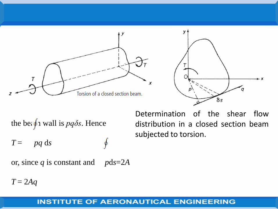
The relationship between the applied torque and this constant shear flow issimply derived by considering the torsional equilibrium of the sectionshown in below Fig.
The torque produced by the shear flow acting on an element δs of Figbelow

Determination of the shear flowdistribution in a closed section beamsubjected to torsion.
the beam wall is pqδs. Hence
T = pq ds
or, since q is constant and pds=2A
T = 2Aq

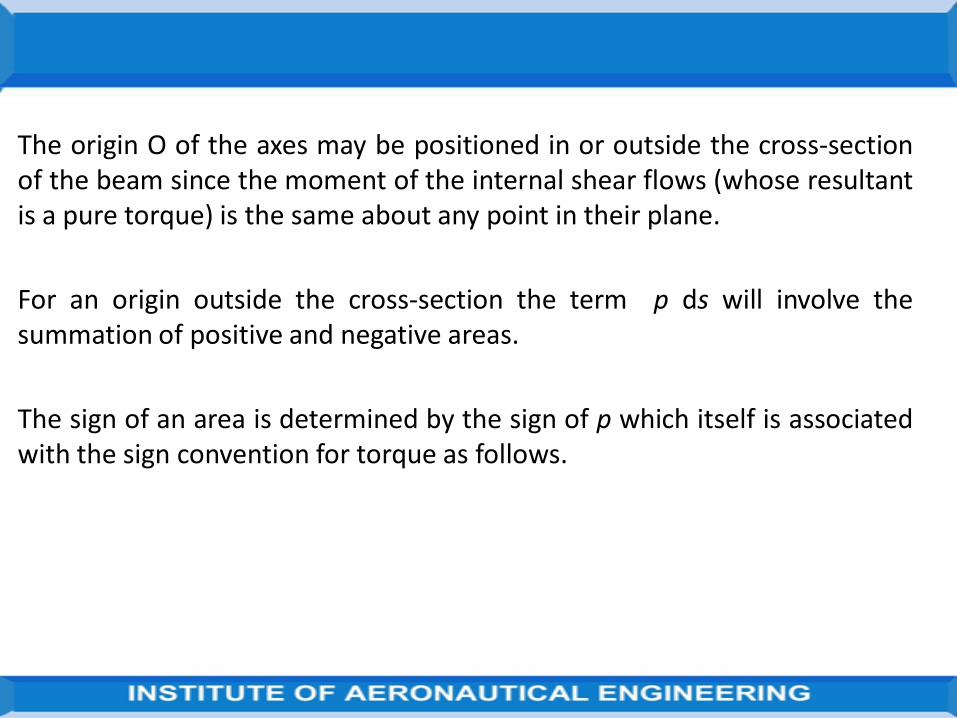
The origin O of the axes may be positioned in or outside the cross-sectionof the beam since the moment of the internal shear flows (whose resultantis a pure torque) is the same about any point in their plane.
For an origin outside the cross-section the term p ds will involve thesummation of positive and negative areas.
The sign of an area is determined by the sign of p which itself is associatedwith the sign convention for torque as follows.

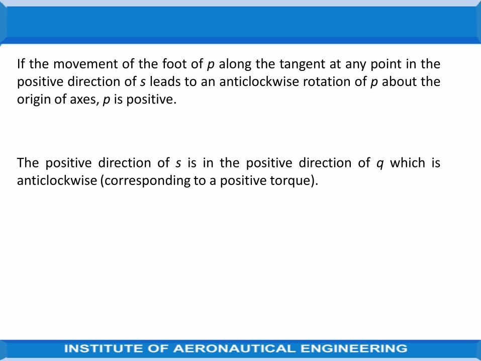
If the movement of the foot of p along the tangent at any point in thepositive direction of s leads to an anticlockwise rotation of p about theorigin of axes, p is positive.
The positive direction of s is in the positive direction of q which isanticlockwise (corresponding to a positive torque).

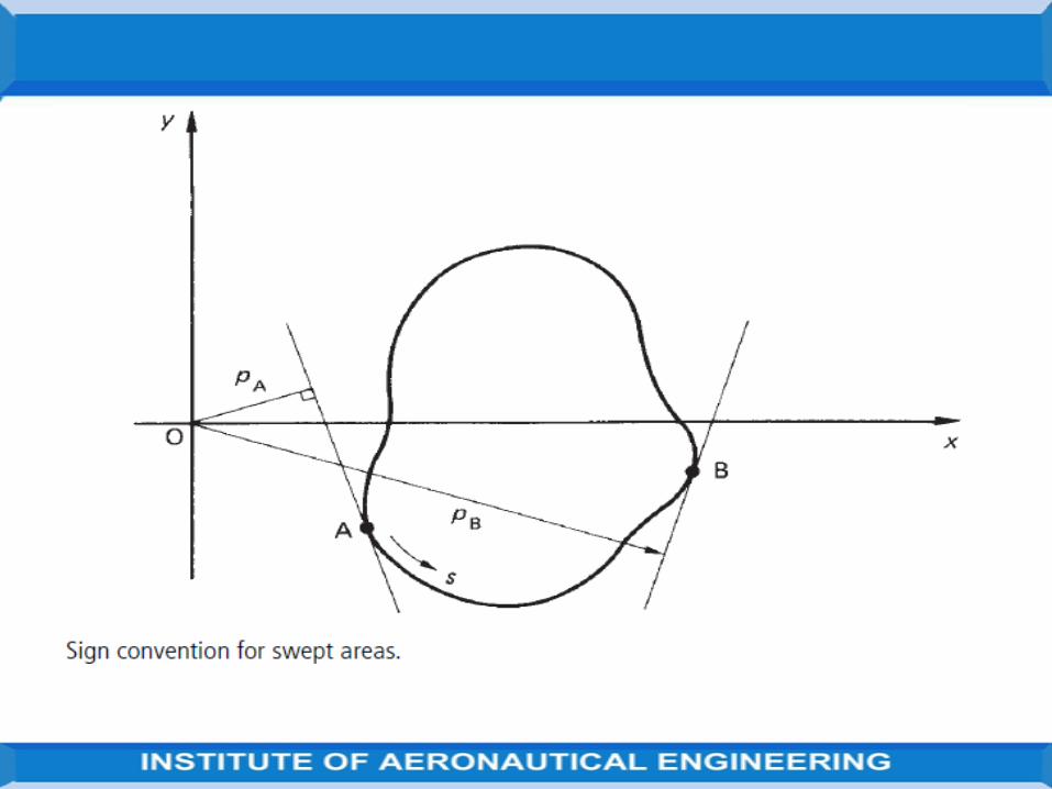
In Fig, a generator OA, rotating about O, will initially sweep out a negativearea since pA is negative.
At B, however, pB is positive so that the area swept out by the generator haschanged sign (at the point where the tangent passes through O and p=0).
Positive and negative areas cancel each other out as they overlap so that asthe generator moves completely around the section, starting and returningto A say, the resultant area is that enclosed by the profile of the beam.
The theory of the torsion of closed section beams is known as the Bredt–Batho theory and Eq. (18.1) is often referred to as the Bredt–Batho formula.
Torsion of closed section beams: Bredt-Batho Equation
A closed section beam subjected to a pure torque T does not, in the absenceof an axial constraint, develop a direct stress system.
It follows that the equilibrium conditions of Eqs
(∂q/∂s)+ t(∂σz/∂z) =0 and
(∂q/∂z)+ t(∂σs/∂s) =0 reduce to
∂q/∂s=0 and ∂q/∂z=0, respectively.
These relationships may only be satisfied simultaneously by a constant valueof q.
Therefore, that the application of a pure torque to a closed section beamresults in the development of a constant shear flow in the beam wall.
The shear stress τ may vary around the cross-section since we allow thewall thickness t to be a function of s.
The relationship between the applied torque and this constant shear flow issimply derived by considering the torsional equilibrium of the sectionshown in below Fig.
The torque produced by the shear flow acting on an element δs of Figbelow
Determination of the shear flowdistribution in a closed section beamsubjected to torsion.
the beam wall is pqδs. Hence
T = pq ds
or, since q is constant and pds=2A
T = 2Aq
The origin O of the axes may be positioned in or outside the cross-sectionof the beam since the moment of the internal shear flows (whose resultantis a pure torque) is the same about any point in their plane.
For an origin outside the cross-section the term p ds will involve thesummation of positive and negative areas.
The sign of an area is determined by the sign of p which itself is associatedwith the sign convention for torque as follows.
If the movement of the foot of p along the tangent at any point in thepositive direction of s leads to an anticlockwise rotation of p about theorigin of axes, p is positive.
The positive direction of s is in the positive direction of q which isanticlockwise (corresponding to a positive torque).

In Fig, a generator OA, rotating about O, will initially sweep out a negativearea since pA is negative.
At B, however, pB is positive so that the area swept out by the generator haschanged sign (at the point where the tangent passes through O and p=0).
Positive and negative areas cancel each other out as they overlap so that asthe generator moves completely around the section, starting and returningto A say, the resultant area is that enclosed by the profile of the beam.
The theory of the torsion of closed section beams is known as the Bredt–Batho theory and Eq. (18.1) is often referred to as the Bredt–Batho formula.
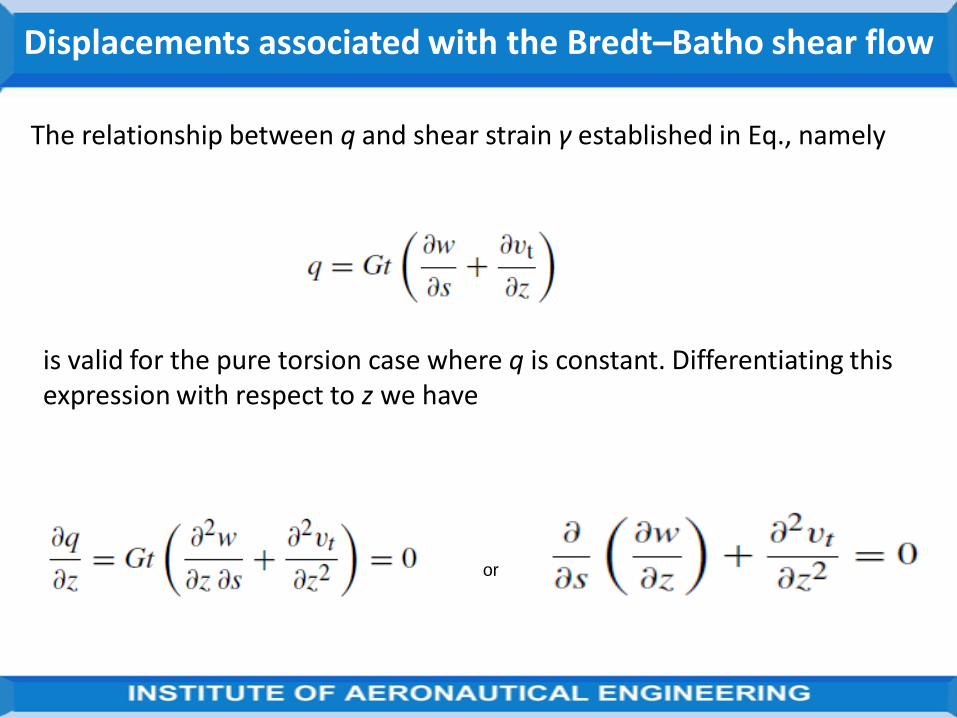
Displacements associated with the Bredt–Batho shear flow
The relationship between q and shear strain γ established in Eq., namely
is valid for the pure torsion case where q is constant. Differentiating this expression with respect to z we have
or
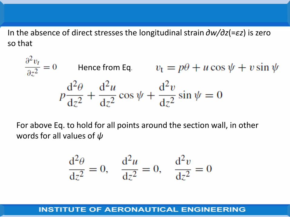
In the absence of direct stresses the longitudinal strain ∂w/∂z(=εz) is zero so that
Hence from Eq.
For above Eq. to hold for all points around the section wall, in other words for all values of ψ
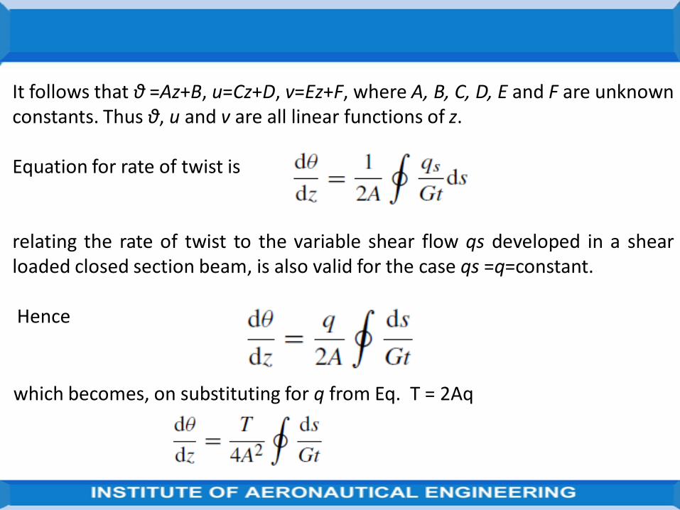
It follows that θ =Az+B, u=Cz+D, v=Ez+F, where A, B, C, D, E and F are unknown constants. Thus θ, u and v are all linear functions of z.
Equation for rate of twist is
relating the rate of twist to the variable shear flow qs developed in a shearloaded closed section beam, is also valid for the case qs =q=constant.
Hence
which becomes, on substituting for q from Eq. T = 2Aq
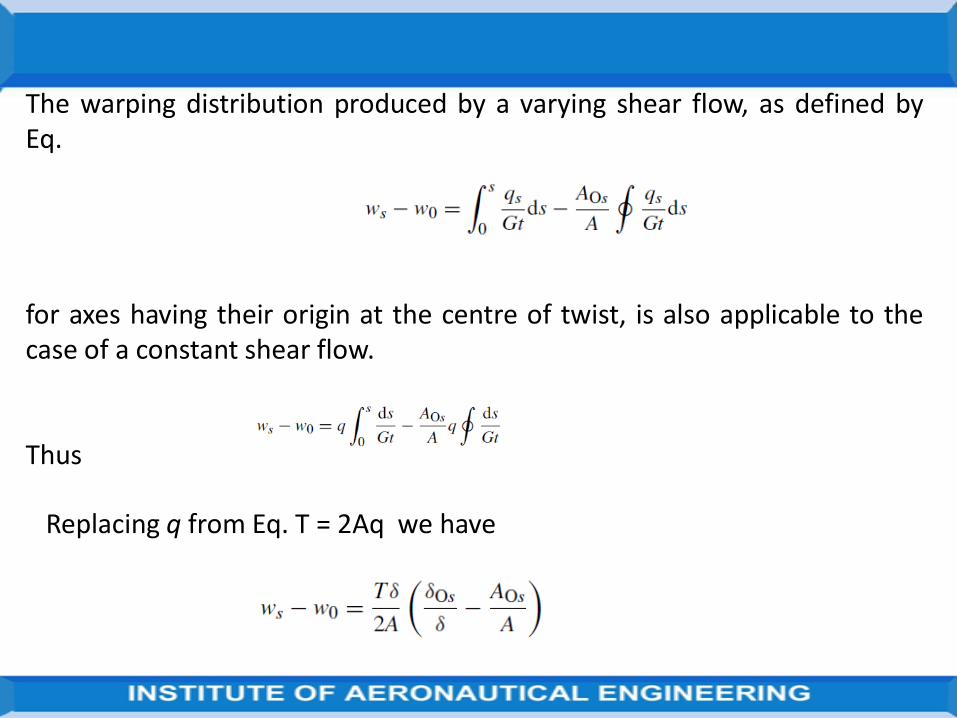
The warping distribution produced by a varying shear flow, as defined byEq.
for axes having their origin at the centre of twist, is also applicable to thecase of a constant shear flow.
Thus
Replacing q from Eq. T = 2Aq we have
The sign of the warping displacement in Eq.
is governed by the sign of the applied torque T and the signs of theparameters δOs and AOs.
Having specified initially that a positive torque is anticlockwise, the signs ofδOs and AOs are fixed in that δOs is positive when s is positive, i.e. s is takenas positive in an anticlockwise sense, and Aos is positive when, as before, p(Fig. below) is positive.


Noted that the longitudinal strain εz is zero in a closed section beamsubjected to a pure torque.
This means that all sections of the beam must possess identical warpingdistributions.
In other words longitudinal generators of the beam surface remainunchanged in length although subjected to axial displacement.

Torsion of open section beamsAn approximate solution for the torsion of a thin-walled open section beammay be found by applying the results obtained for the torsion of a thinrectangular strip.
If such a strip is bent to form an open section beam, as shown in Fig. in nextslide and if the distance s measured around the cross-section is largecompared with its thickness t then the contours of the membrane,
i.e. lines of shear stress, are still approximately parallel to the inner andouter boundaries.
It follows that the shear lines in an element δs of the open section must benearly the same as those in an element δy of a rectangular strip
Source from Aircraft Structures by T. H. G. Megson

(a) Shear lines in a thin-walled open section beam subjected to torsion;
(b) approximation of elemental shear lines to those in a thin rectangular strip.
Source from Aircraft Structures by T. H. G. Megson

Source from Aircraft Structures by T. H. G. Megson

Above equation the second expression for the torsion constant is used ifthe cross-section has a variable wall thickness.
Finally, the rate of twist is expressed in terms of the applied torque
Source from Aircraft Structures by T. H. G. Megson

The shear stress distribution and the maximum shear stress are sometimesmore conveniently expressed in terms of the applied torque.
Therefore, substituting for dθ/dz in Eqs
and
gives
Source from Aircraft Structures by T. H. G. Megson

We assume in open beam torsion analysis that the cross-section ismaintained by the system of closely spaced diaphragms described and thatthe beam is of uniform section.
Clearly, in this problem the shear stresses vary across the thickness of thebeam wall whereas other stresses such as axial constraint stresses areassumed constant across the thickness.
Source from Aircraft Structures by T. H. G. Megson

Warping of the cross-section
The thin rectangular strip suffers warping across its thickness whensubjected to torsion.
In the same way a thin-walled open section beam will warp across itsthickness.
This warping, wt, may be deduced by comparing Fig.
with Fig. next slide

and using Eq.

In addition to warping across the thickness, the cross-section of the beamwill warp in a similar manner to that of a closed section beam.
Referring the tangential displacement vt to the centre of twist R of the cross-section
we have, from Eq

Substituting for ∂vt/∂z
On the mid-line of the section wall τzs = 0
Integrating this expression with respect to s and taking the lower limit of integration to coincide with the point of zero warping, we obtain

It can be seen that two types of warping exist in an open section beam. The above
equation gives the warping of the mid-line of the beam; this is known as primary
warping and is assumed to be constant across the wall thickness.
Equation
gives the warping of the beam across its wall thickness.
This is called secondary warping, is very much less than primary warping and is
usually ignored in the thin-walled sections common to aircraft structures.
Equation may be rewritten in the form


or, in terms of the applied torque
in which is the area swept out by a generator, rotating about the
centre of twist, from the point of zero warping .
The sign of ws, for a given direction of torque, depends upon the sign of AR which in
turn depends upon the sign of PR.

The perpendicular distance from the center of twist to the tangent at anypoint.
Again, as for closed section beams, the sign of pR depends upon the assumeddirection of a positive torque, in this case anticlockwise.
Therefore, pR (and therefore AR) is positive if movement of the foot of pR alongthe tangent in the assumed direction of s leads to an anticlockwise rotation ofpR about the center of twist.
For open section beams the positive direction of s may be chosen arbitrarilysince, for a given torque, the sign of the warping displacement depends onlyon the sign of the swept area AR.

Condition for zero warping at a section
The geometry of the cross-section of a closed section beam subjected totorsion may be such that no warping of the cross-section occurs.
This condition arises when or
Differentiating above Eq. with respect to s gives
or

A closed section beam for which pRGt =constant does not warp and is knownas a Neuber beam.
For closed section beams having a constant shear modulus the conditionbecomes pRt = constant
Examples of such beams are a circular section beam of constant thickness, arectangular section beam for which atb =bta , and a triangular section beamof constant thickness.
In the last case the shear centre and hence the centre of twist may beshown to coincide with the centre of the inscribed circle so that pR for eachside is the radius of the inscribed circle.

Combined open and closed section beams
So far, we have analyzed thin-walled beams which consist of either completelyclosed cross-sections or completely open cross-sections.
Frequently aircraft components comprise combinations of open and closedsection beams.
For example the section of a wing in the region of an undercarriage bay couldtake the form shown in Fig.

Clearly part of the section is an open channel section while the nose portion isa single cell closed section.
We shall now examine the methods of analysis of such sections whensubjected to bending, shear and torsional loads.
Bending
It is immaterial what form the cross-section of a beam takes; the directstresses due to bending are given by either of below Eqs.

Shear
The methods described in Shear of open section Beams and Shear ofclosed section Beams are used to determine the shear stress distribution.
Although, unlike the completely closed section case, shear loads must beapplied through the shear centre of the combined section.
Otherwise shear stresses of the type described in Torsion of open sectionBeams due to torsion will arise.
Where shear loads do not act through the shear centre its position must befound and the loading system replaced

By shear loads acting through the shear centre together with a torque; thetwo loading cases are then analysed separately.
Again we assume that the cross-section of the beam remains undistorted bythe loading.

Torsion
Generally, in the torsion of composite sections, the closed portion isdominant
since its torsional stiffness is far greater than that of the attached opensection portion
which may therefore be frequently ignored in the calculation of torsionalstiffness;
shear stresses should, however, be checked in this part of the section.

UNIT IV
STRUCTURAL IDEALIZATION

Structural idealization
So far we have been concerned with relatively uncomplicated structural sectionswhich in practice would be formed from thin plate or by the extrusion process.
While these sections exist as structural members in their own right they arefrequently used, to stiffen more complex structural shapes such as fuselages, wingsand tail surfaces.
Thus a two spar wing section could take the form shown in below Fig.
Source from Aircraft Structures by T. H. G. Megson

Above fig. Z-section stringers are used to stiffen the thin skin while anglesections form the spar flanges.
Clearly, the analysis of a section of this type would be complicated andtedious unless some simplifying assumptions are made.
Generally, the number and nature of these simplifying assumptionsdetermine the accuracy and the degree of complexity of the analysis; themore complex the analysis the greater the accuracy obtained.
The degree of simplification introduced is governed by the particularsituation surrounding the problem.
Source from Aircraft Structures by T. H. G. Megson

For a preliminary investigation, speed and simplicity are often of greaterimportance than extreme accuracy; on the other hand a final solution mustbe as exact as circumstances allow.
Complex structural sections may be idealized into simpler ‘mechanicalmodel’forms which behave, under given loading conditions, in the same, orvery nearly the same, way as the actual structure.
We shall see, that different models of the same structure are required tosimulate actual behaviour under different systems of loading.
Source from Aircraft Structures by T. H. G. Megson

PrincipleIn the wing section of Fig. below the stringers and spar flanges have small cross-sectional dimensions compared with the complete section.
Source from Aircraft Structures by T. H. G. Megson

The variation in stress over the cross-section of a stringer due to, say,bending of the wing would be small.
The difference between the distances of the stringer centroids and theadjacent skin from the wing section axis is small.
It would be reasonable to assume therefore that the direct stress is constantover the stringer cross-sections.
We could therefore replace the stringers and spar flanges by concentrationsof area, known as booms,
over which the direct stress is constant and which are located along themidline of the skin, as shown in above Fig.
Source from Aircraft Structures by T. H. G. Megson

In wing and fuselage sections of the type shown in above Fig., the stringersand spar flanges carry most of the direct stresses while the skin is mainlyeffective in resisting shear stresses although it also carries some of thedirect stresses.
The idealization shown in above Fig. may therefore be taken a stage furtherby assuming that all direct stresses are carried by the booms while the skinis effective only in shear.
The direct stress carrying capacity of the skin may be allowed for byincreasing each boom area by an area equivalent to the direct stresscarrying capacity of the adjacent skin panels.
The calculation of these equivalent areas will generally depend upon aninitial assumption as to the form of the distribution of direct stress in aboom/skin panel.
Source from Aircraft Structures by T. H. G. Megson

Idealization of a panel
Idealization of a panel.
Source from Aircraft Structures by T. H. G. Megson

Idealization of a panel
Wish to idealize the panel of above Fig. into a combination of direct stresscarrying booms and shear stress only carrying skin as shown in above Fig.
The direct stress carrying thickness tD of the skin is equal to its actualthickness t while tD =0.
Suppose also that the direct stress distribution in the actual panel varieslinearly from an unknown value σ1 to an unknown value σ2.
Clearly the analysis should predict the extremes of stress σ1 and σ2 althoughthe distribution of direct stress is obviously lost.
Source from Aircraft Structures by T. H. G. Megson

Since the loading producing the direct stresses in the actual and idealizedpanels must be the same
we can equate moments to obtain expressions for the boom areas B1 and B2.
Thus, taking moments about the right-hand edge of each panel,
Source from Aircraft Structures by T. H. G. Megson

In above Eqs, the ratio of σ1 to σ2, if not known, may frequently be assumed.
The direct stress distribution in above Fig. is caused by a combination of axialload and bending moment.
For axial load only σ1/σ2 =1 and B1 =B2 =tDb/2; for a pure bending momentσ1/σ2=−1 and B1 =B2 =tDb/6.
Thus, different idealizations of the same structure are required for differentloading conditions.
Source from Aircraft Structures by T. H. G. Megson

Effect of idealization on the analysis of open and closed section beams
The addition of direct stress carrying booms to open and closed sectionbeams will clearly modify the analyses presented.
Before considering individual cases we shall discuss the implications ofstructural idealization.
Generally, in any idealization, different loading conditions require differentidealizations of the same structure.
Suppose the loading is applied in a vertical plane. If, however, the loadinghad been applied in a horizontal plane the assumed stress distribution in thepanels of the section would have been different, resulting in different valuesof boom area.
Source from Aircraft Structures by T. H. G. Megson

Suppose that an open or closed section beam is subjected to given bending orshear loads and that the required idealization has been completed.
The analysis of such sections usually involves the determination of the neutralaxis position and the calculation of sectional properties.
The position of the neutral axis is derived from the condition that theresultant load on the beam cross-section is zero, i.e.
The area A in this expression is clearly the direct stress carrying area. It followsthat the centroid of the cross-section is the centroid of the direct stresscarrying area of the section, depending on the degree and method ofidealization. The sectional properties, Ixx, etc., must also refer to the directstress carrying area. Source from Aircraft Structures by T. H. G. Megson

Example The fuselage section shown in Fig. is subjected to a bending moment of 100kNm applied in the vertical plane of symmetry. If the section has beencompletely idealized into a combination of direct stress carrying booms andshear stress only carrying panels, determine the direct stress in each boom.
The section has Cy as an axis of symmetry and resists a bending moment Mx
=100 kN m. Equation therefore reduces to
The origin of axes Cxy coincides with the position of the centroid of the directstress carrying area which, in this case, is the centroid of the boom areas.
Thus, taking moments of area about boom 9
Source from Aircraft Structures by T. H. G. Megson

Idealized fuselage sectionSource from Aircraft Structures by T. H. G. Megson

(6 × 640 + 6 × 600 + 2 × 620 + 2 × 850)y
= 640 × 1200 + 2 × 600 × 1140 + 2 × 600 × 960 + 2 × 600 × 768
+ 2 × 620 × 565 + 2 × 640 × 336 + 2 × 640 × 144 + 2 × 850 × 38
Source from Aircraft Structures by T. H. G. Megson

which gives y = 540mm
The solution is now completed in above Table
From column ➃ Ixx = 1854 × 106 mm4
Source from Aircraft Structures by T. H. G. Megson

Effect of idealization on the analysis of open and closed section beams
The direct stress carrying booms to open and closed section beams .
Generally, in any idealization, different loading conditions require differentidealizations of the same structure.
The loading had been applied in a horizontal plane the assumed stressdistribution in the panels of the section would have been different, resulting indifferent values of boom area.
Suppose that an open or closed section beam is subjected to given bending orshear loads and that the required idealization has been completed.
The analysis of such sections usually involves the determination of the neutralaxis position and the calculation of sectional properties
The position of the neutral axis is derived from the condition that the resultant load on the beam cross-section is zero, i.e.
The area A in this expression is clearly the direct stress carrying area.
It follows that the centroid of the cross-section is the centroid of the directstress carrying area of the section, depending on the degree and method ofidealization.
The sectional properties, Ixx, etc., must also refer to the direct stress carryingarea.
Bending of open and closed section beams
The direct stress distribution is given by any of Eqs
depending on the beam section being investigated.
In these equations the coordinates (x, y) of points in the cross-section arereferred to axes having their origin at the centroid of the direct stress carryingarea.
Furthermore, the section properties Ixx, Iyy and Ixy are calculated for thedirect stress carrying area only.
In the case where the beam cross-section has been completely idealized intodirect stress carrying booms and shear stress only carrying panels, the directstress distribution consists of a series of direct stresses concentrated at thecentroids of the booms.
Ex: The fuselage section shown in Fig. below is subjected to a bendingmoment of 100 kNm applied in the vertical plane of symmetry.
If the section has been completely idealized into a combination of directstress carrying booms and shear stress only carrying panels, determine thedirect stress in each boom.
The section has Cy as an axis of symmetry and resists a bending moment
Mx =100 kN m. Equation therefore reduces to
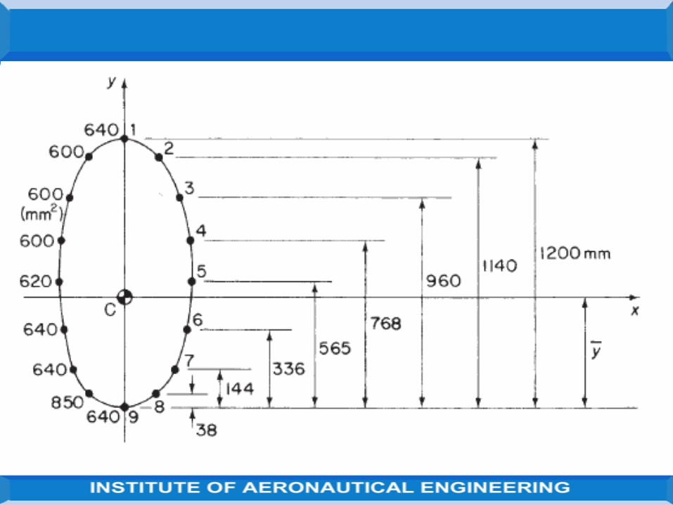
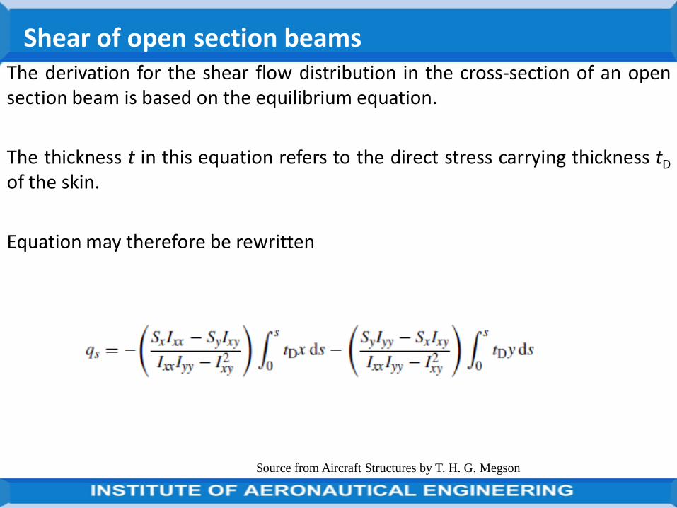
The derivation for the shear flow distribution in the cross-section of an opensection beam is based on the equilibrium equation.
The thickness t in this equation refers to the direct stress carrying thickness tD
of the skin.
Equation may therefore be rewritten
Shear of open section beams
Source from Aircraft Structures by T. H. G. Megson
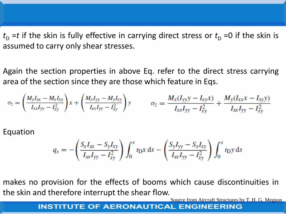
tD =t if the skin is fully effective in carrying direct stress or tD =0 if the skin isassumed to carry only shear stresses.
Again the section properties in above Eq. refer to the direct stress carryingarea of the section since they are those which feature in Eqs.
Equation
makes no provision for the effects of booms which cause discontinuities inthe skin and therefore interrupt the shear flow.
Source from Aircraft Structures by T. H. G. Megson
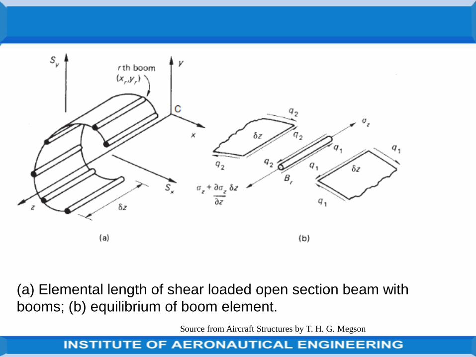
(a) Elemental length of shear loaded open section beam with
booms; (b) equilibrium of boom element.
Source from Aircraft Structures by T. H. G. Megson
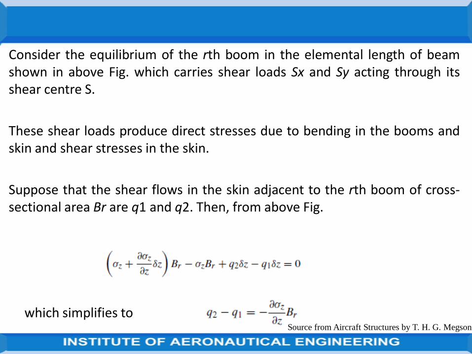
Consider the equilibrium of the rth boom in the elemental length of beamshown in above Fig. which carries shear loads Sx and Sy acting through itsshear centre S.
These shear loads produce direct stresses due to bending in the booms andskin and shear stresses in the skin.
Suppose that the shear flows in the skin adjacent to the rth boom of cross-sectional area Br are q1 and q2. Then, from above Fig.
which simplifies toSource from Aircraft Structures by T. H. G. Megson
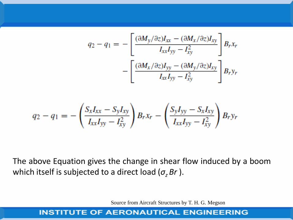
The above Equation gives the change in shear flow induced by a boomwhich itself is subjected to a direct load (σz Br ).
Source from Aircraft Structures by T. H. G. Megson
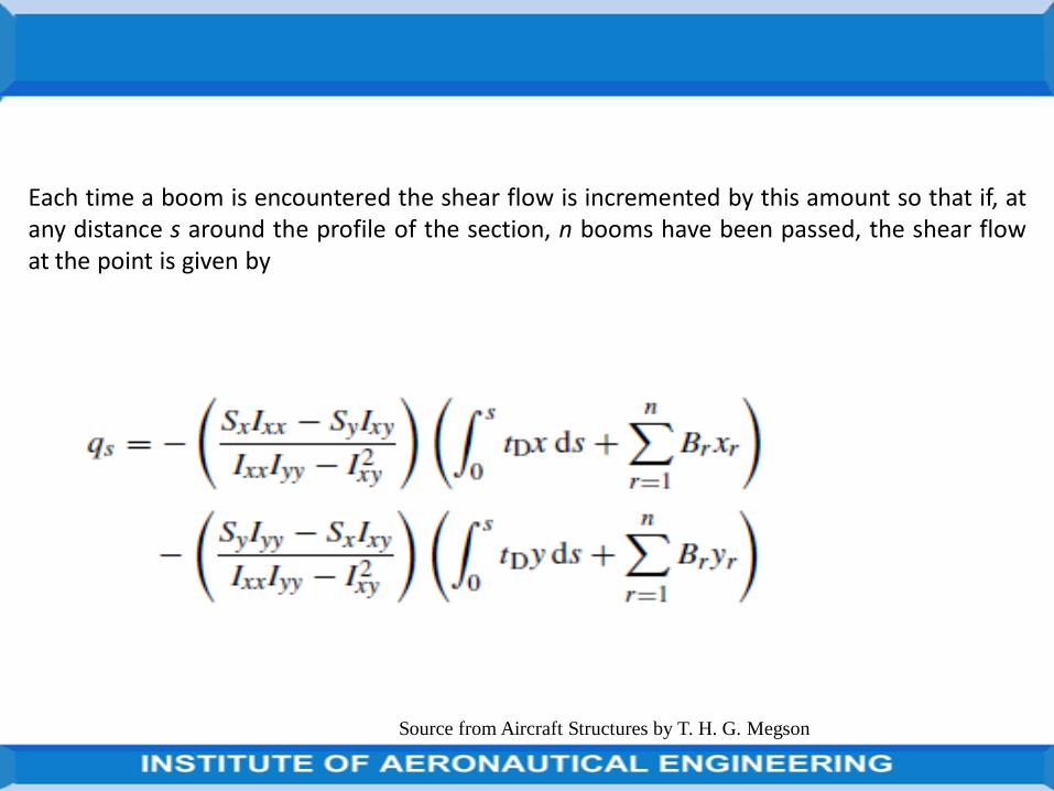
Each time a boom is encountered the shear flow is incremented by this amount so that if, atany distance s around the profile of the section, n booms have been passed, the shear flowat the point is given by
Source from Aircraft Structures by T. H. G. Megson
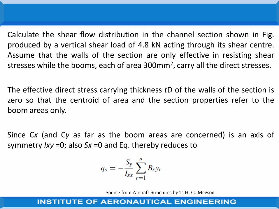
Calculate the shear flow distribution in the channel section shown in Fig.produced by a vertical shear load of 4.8 kN acting through its shear centre.Assume that the walls of the section are only effective in resisting shearstresses while the booms, each of area 300mm2, carry all the direct stresses.
The effective direct stress carrying thickness tD of the walls of the section iszero so that the centroid of area and the section properties refer to theboom areas only.
Since Cx (and Cy as far as the boom areas are concerned) is an axis ofsymmetry Ixy =0; also Sx =0 and Eq. thereby reduces to
Source from Aircraft Structures by T. H. G. Megson
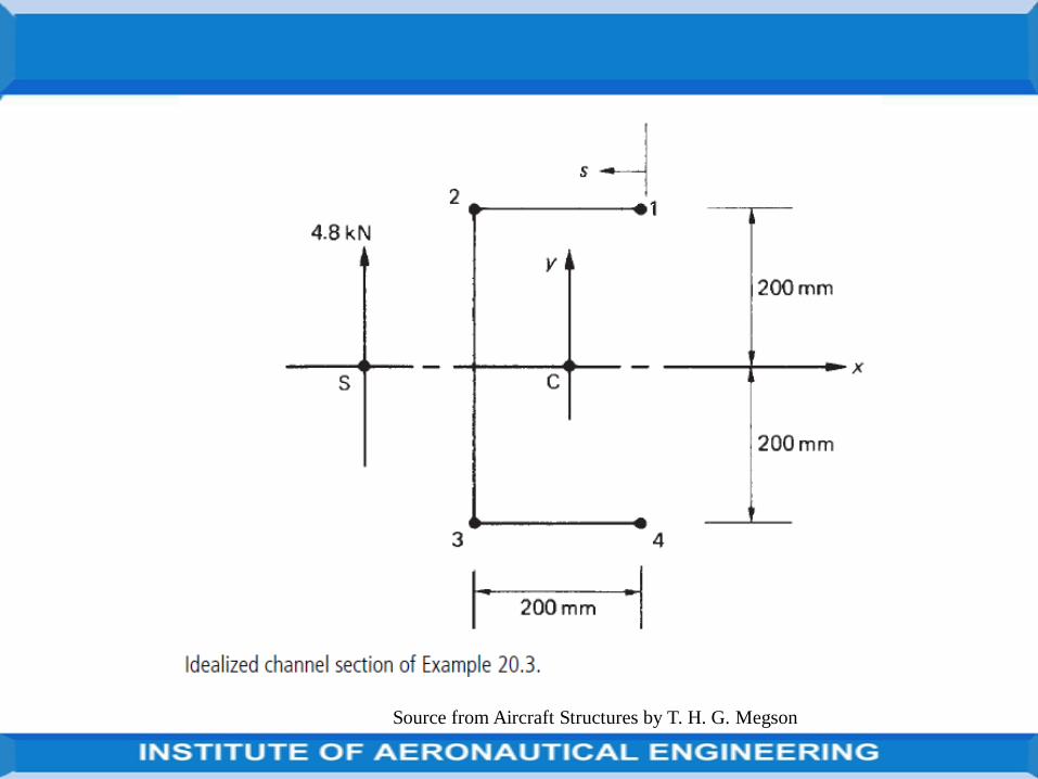
Source from Aircraft Structures by T. H. G. Megson
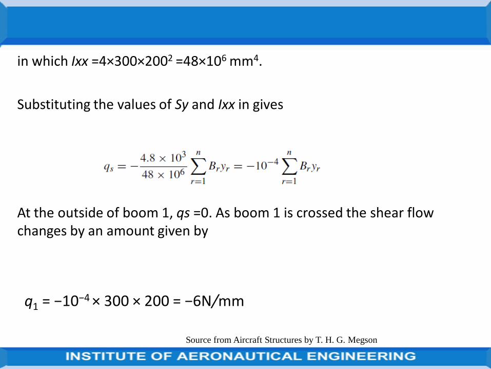
in which Ixx =4×300×2002 =48×106 mm4.
Substituting the values of Sy and Ixx in gives
At the outside of boom 1, qs =0. As boom 1 is crossed the shear flow changes by an amount given by
q1 = −10−4 × 300 × 200 = −6N/mm
Source from Aircraft Structures by T. H. G. Megson
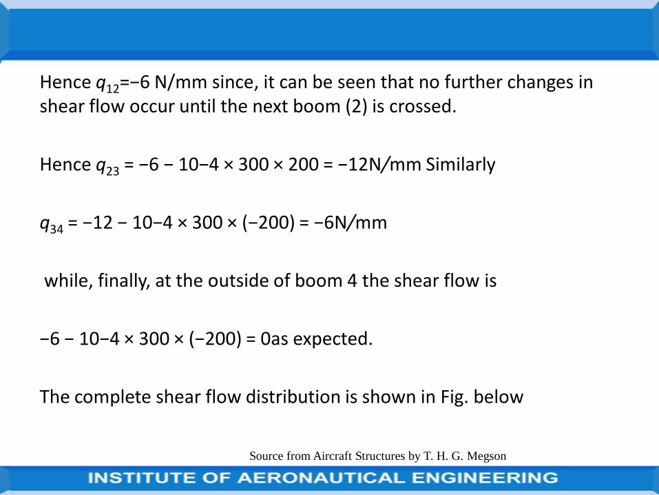
Hence q12=−6 N/mm since, it can be seen that no further changes in shear flow occur until the next boom (2) is crossed.
Hence q23 = −6 − 10−4 × 300 × 200 = −12N/mm Similarly
q34 = −12 − 10−4 × 300 × (−200) = −6N/mm
while, finally, at the outside of boom 4 the shear flow is
−6 − 10−4 × 300 × (−200) = 0as expected.
The complete shear flow distribution is shown in Fig. below
Source from Aircraft Structures by T. H. G. Megson
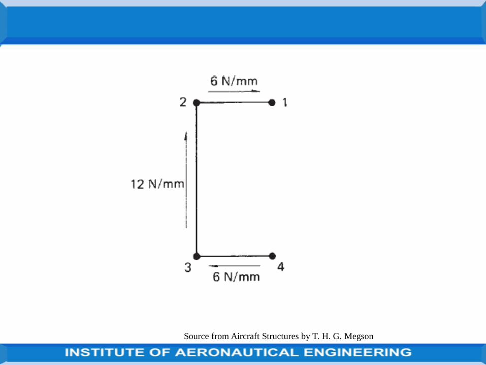
Source from Aircraft Structures by T. H. G. Megson
The thin-walled single cell beam shown in Fig. below has been idealized into acombination of direct stress carrying booms and shear stress only carryingwalls. If the section supports a vertical shear load of 10 kN acting in a verticalplane through booms 3 and 6, calculate the distribution of shear flow aroundthe section.
Boom areas: B1 =B8 =200mm2, B2 =B7 =250mm2, B3 =B6 =400mm2, B4 =
B5 =100mm2.
The centroid of the direct stress carrying area lies on the horizontal axis ofsymmetry so that Ixy =0. Also, since tD =0 and only a vertical shear load isapplied
Source from Aircraft Structures by T. H. G. Megson
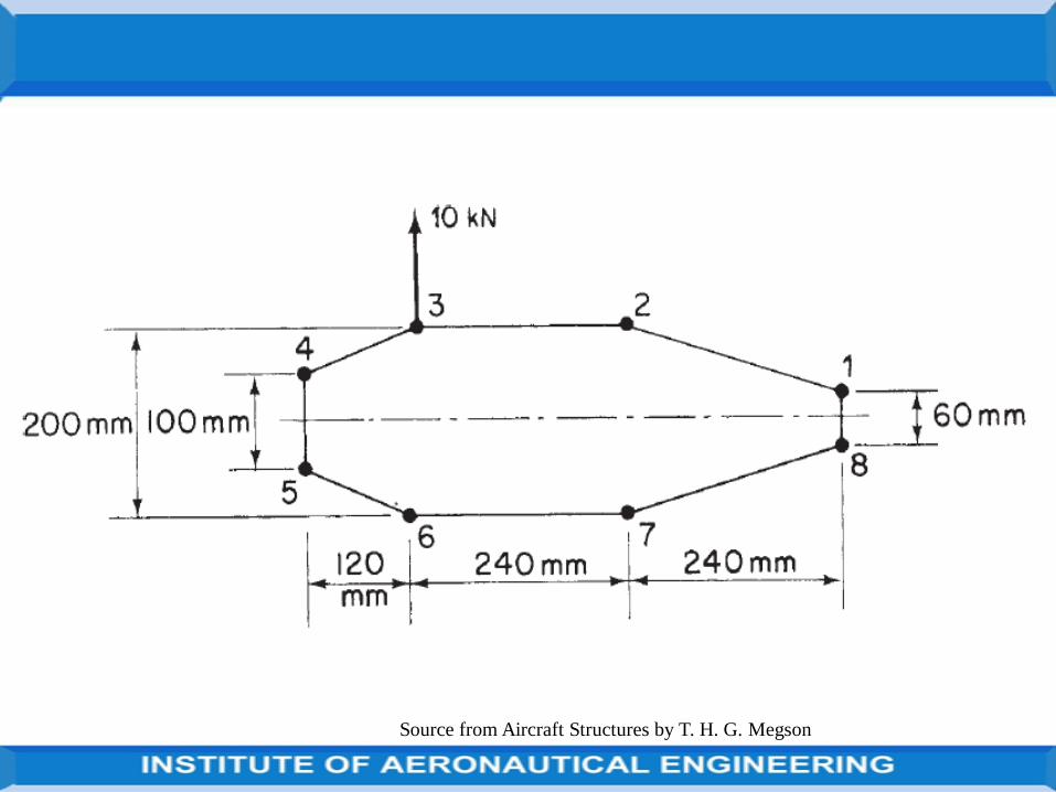
Source from Aircraft Structures by T. H. G. Megson
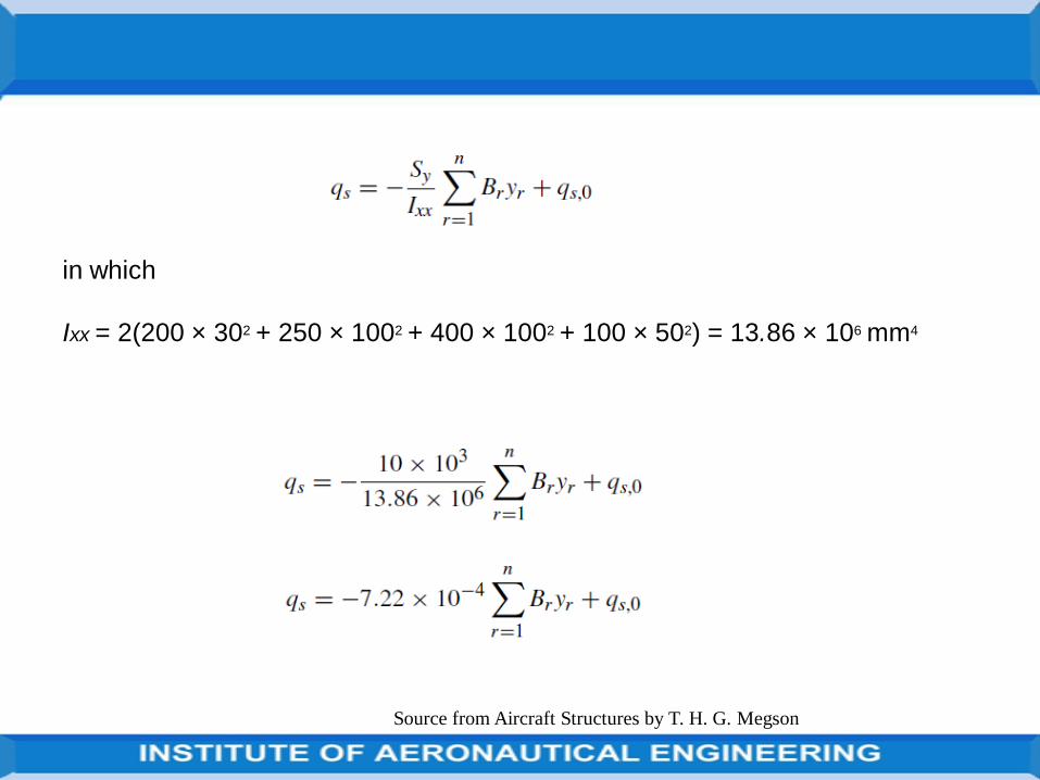
Source from Aircraft Structures by T. H. G. Megson
in which
Ixx = 2(200 × 302 + 250 × 1002 + 400 × 1002 + 100 × 502) = 13.86 × 106 mm4
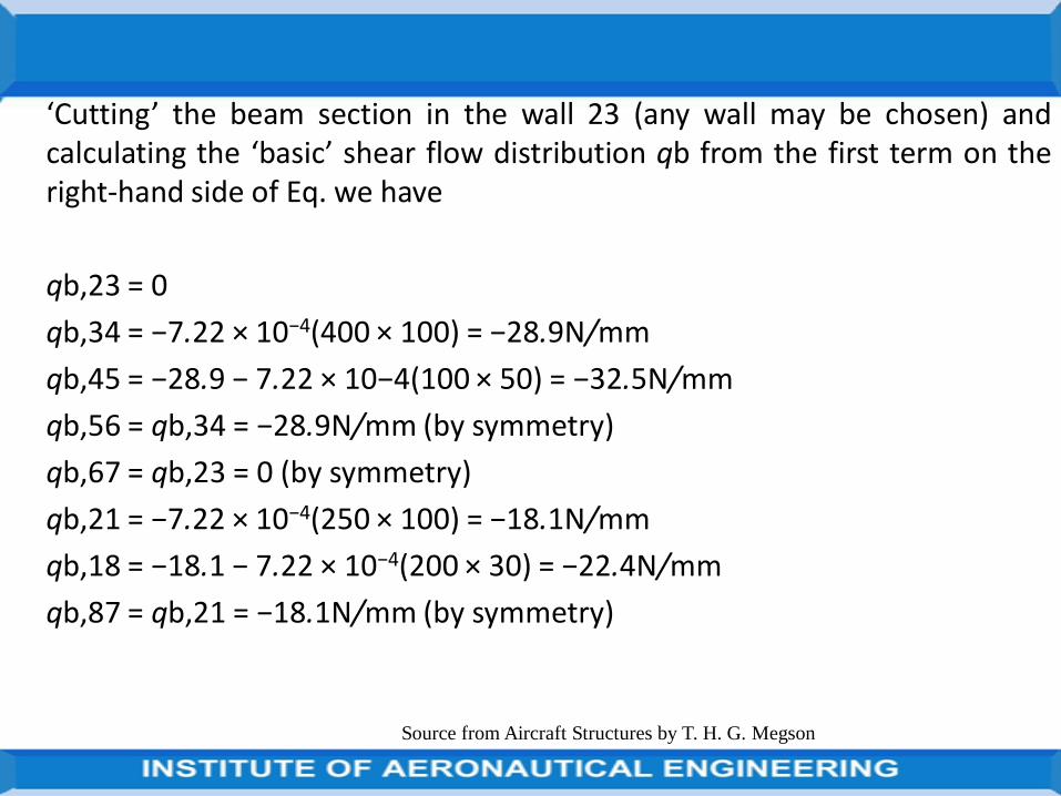
‘Cutting’ the beam section in the wall 23 (any wall may be chosen) andcalculating the ‘basic’ shear flow distribution qb from the first term on theright-hand side of Eq. we have
qb,23 = 0
qb,34 = −7.22 × 10⁻⁴(400 × 100) = −28.9N/mm
qb,45 = −28.9 − 7.22 × 10⁻⁴(100 × 50) = −32.5N/mm
qb,56 = qb,34 = −28.9N/mm (by symmetry)
qb,67 = qb,23 = 0 (by symmetry)
qb,21 = −7.22 × 10⁻⁴(250 × 100) = −18.1N/mm
qb,18 = −18.1 − 7.22 × 10⁻⁴(200 × 30) = −22.4N/mm
qb,87 = qb,21 = −18.1N/mm (by symmetry)
Source from Aircraft Structures by T. H. G. Megson
Taking moments about the intersection of the line of action of the shear loadand the horizontal axis of symmetry and referring to the results of Eqs .
0 = [qb,81 × 60 × 480 + 2qb,12(240 × 100 + 70 × 240) + 2qb,23 × 240 × 100
− 2qb,43 × 120 × 100 − qb,54 × 100 × 120] + 2 × 97 200qs,0
Substituting the above values of qb in this equation gives
qs,0 = −5.4N/mm
the negative sign indicating that qs,0 acts in a clockwise sense.
In any wall the final shear flow is given by qs =qb +qs,0 so that
q21 = −18.1 + 5.4 = −12.7N/mm = q87
q23 = −5.4N/mm = q67
Source from Aircraft Structures by T. H. G. Megson
q34 = −34.3N/mm = q56
q45 = −37.9N/mm
And
q81 = 17.0N/mm
giving the shear flow distribution shown in Fig. below.
Source from Aircraft Structures by T. H. G. Megson
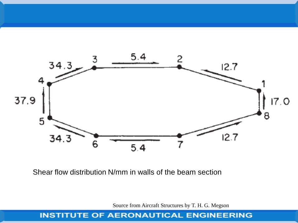
Source from Aircraft Structures by T. H. G. Megson
Shear flow distribution N/mm in walls of the beam section
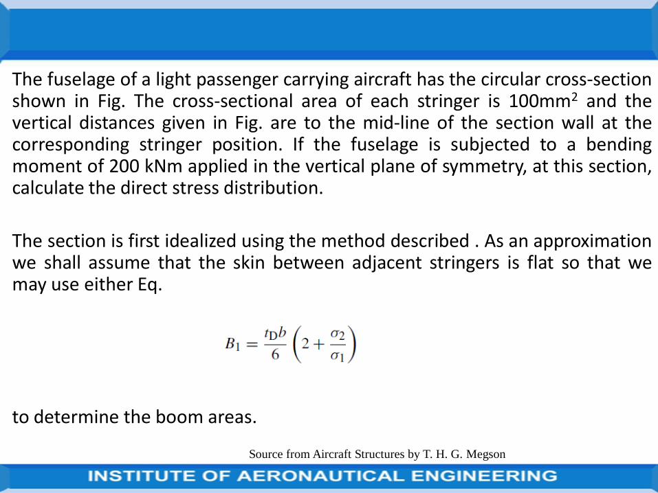
The fuselage of a light passenger carrying aircraft has the circular cross-sectionshown in Fig. The cross-sectional area of each stringer is 100mm2 and thevertical distances given in Fig. are to the mid-line of the section wall at thecorresponding stringer position. If the fuselage is subjected to a bendingmoment of 200 kNm applied in the vertical plane of symmetry, at this section,calculate the direct stress distribution.
The section is first idealized using the method described . As an approximationwe shall assume that the skin between adjacent stringers is flat so that wemay use either Eq.
to determine the boom areas.
Source from Aircraft Structures by T. H. G. Megson
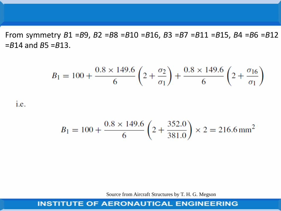
From symmetry B1 =B9, B2 =B8 =B10 =B16, B3 =B7 =B11 =B15, B4 =B6 =B12=B14 and B5 =B13.
Source from Aircraft Structures by T. H. G. Megson
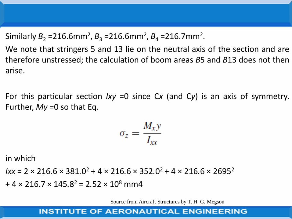
Similarly B2 =216.6mm2, B3 =216.6mm2, B4 =216.7mm2.
We note that stringers 5 and 13 lie on the neutral axis of the section and aretherefore unstressed; the calculation of boom areas B5 and B13 does not thenarise.
For this particular section Ixy =0 since Cx (and Cy) is an axis of symmetry.Further, My =0 so that Eq.
in which
Ixx = 2 × 216.6 × 381.02 + 4 × 216.6 × 352.02 + 4 × 216.6 × 26952
+ 4 × 216.7 × 145.82 = 2.52 × 108 mm4
Source from Aircraft Structures by T. H. G. Megson
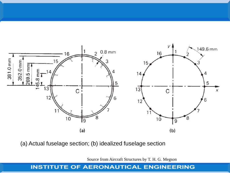
Source from Aircraft Structures by T. H. G. Megson
(a) Actual fuselage section; (b) idealized fuselage section
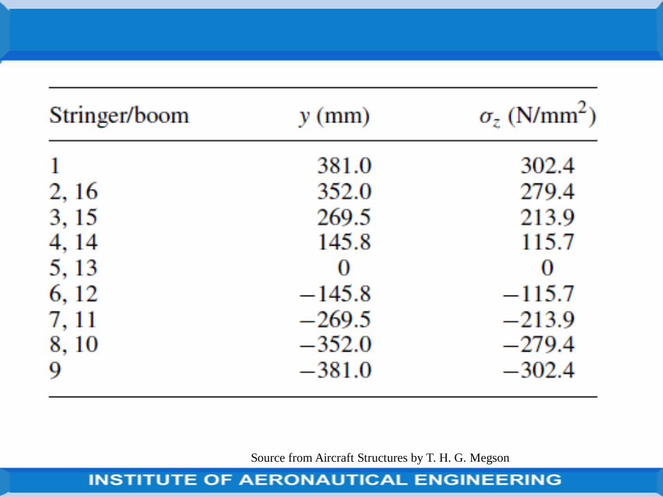
Source from Aircraft Structures by T. H. G. Megson
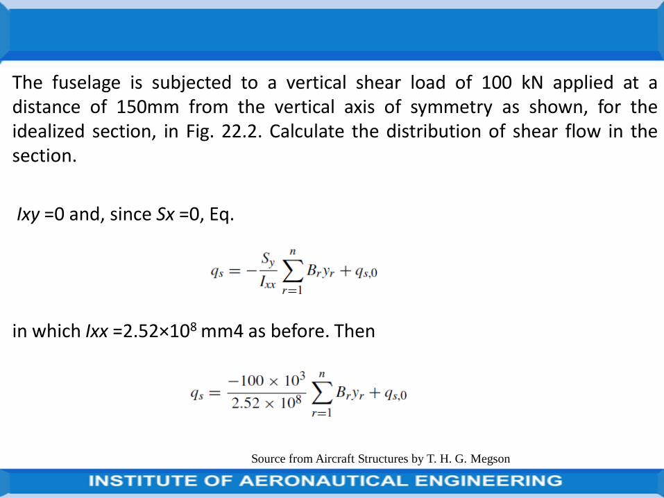
The fuselage is subjected to a vertical shear load of 100 kN applied at adistance of 150mm from the vertical axis of symmetry as shown, for theidealized section, in Fig. 22.2. Calculate the distribution of shear flow in thesection.
Ixy =0 and, since Sx =0, Eq.
in which Ixx =2.52×108 mm4 as before. Then
Source from Aircraft Structures by T. H. G. Megson
The first term on the right-hand side of Eq. is the ‘open section’ shear flow qb.
We therefore ‘cut’one of the skin panels, say 12, and calculate qb.
The results are presented in Table. , the column headed Boom indicates theboom that is crossed when the analysis moves from one panel to the next.
Note also that, as would be expected, the qb shear flow distribution issymmetrical about the Cx axis.
The shear flow qs,0 in the panel 12 is now found by taking moments about aconvenient moment centre, say C. Therefore from Eq.
Source from Aircraft Structures by T. H. G. Megson
Source from Aircraft Structures by T. H. G. Megson
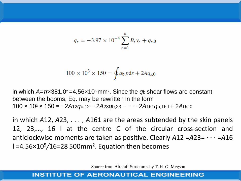
Source from Aircraft Structures by T. H. G. Megson
in which A=π×381.02 =4.56×105 mm2. Since the qb shear flows are constant
between the booms, Eq. may be rewritten in the form
100 × 103 × 150 = −2A12qb,12 − 2A23qb,23 −· · ·−2A161qb,16 l + 2Aqs,0
in which A12, A23, . . . , A161 are the areas subtended by the skin panels12, 23,…, 16 l at the centre C of the circular cross-section andanticlockwise moments are taken as positive. Clearly A12 =A23= · · · =A16l =4.56×10⁵/16=28 500mm2. Equation then becomes
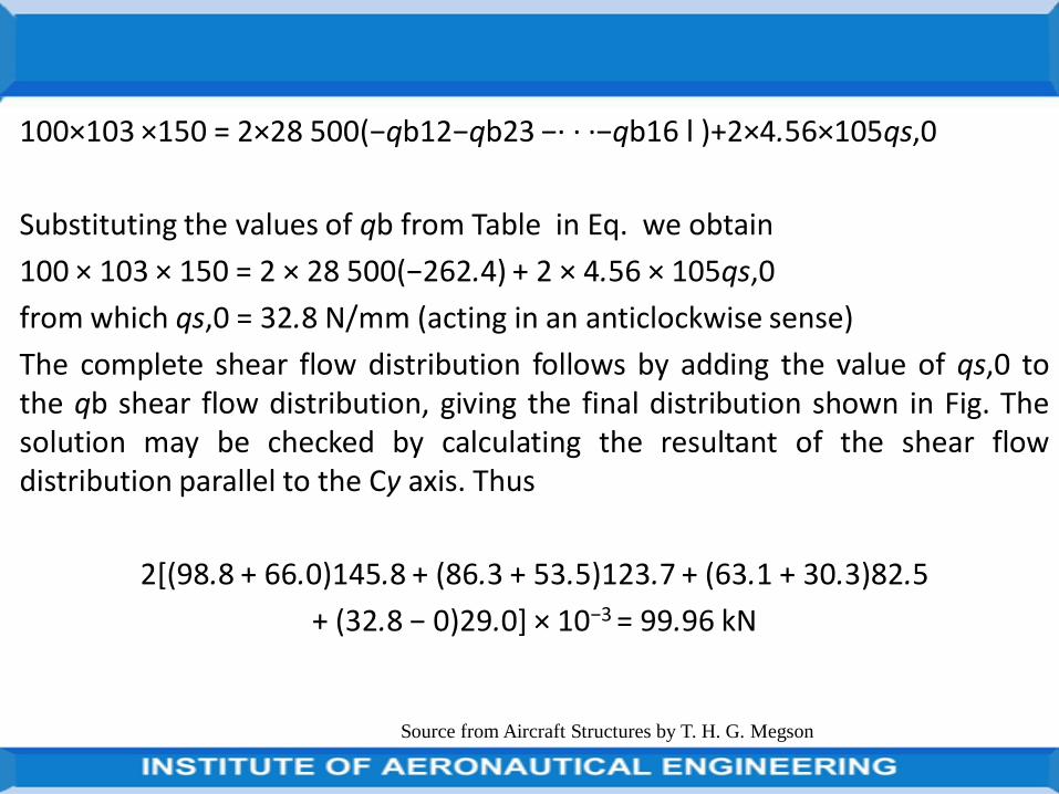
100×103 ×150 = 2×28 500(−qb12−qb23 −· · ·−qb16 l )+2×4.56×105qs,0
Substituting the values of qb from Table in Eq. we obtain
100 × 103 × 150 = 2 × 28 500(−262.4) + 2 × 4.56 × 105qs,0
from which qs,0 = 32.8 N/mm (acting in an anticlockwise sense)
The complete shear flow distribution follows by adding the value of qs,0 tothe qb shear flow distribution, giving the final distribution shown in Fig. Thesolution may be checked by calculating the resultant of the shear flowdistribution parallel to the Cy axis. Thus
2[(98.8 + 66.0)145.8 + (86.3 + 53.5)123.7 + (63.1 + 30.3)82.5
+ (32.8 − 0)29.0] × 10−3 = 99.96 kN
Source from Aircraft Structures by T. H. G. Megson
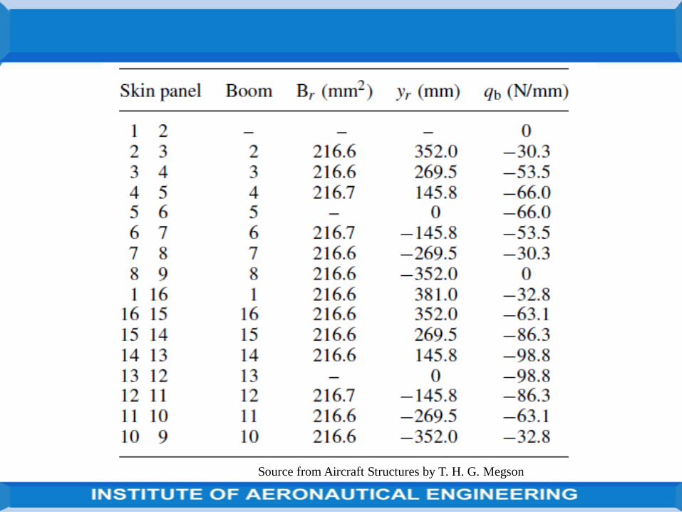
Source from Aircraft Structures by T. H. G. Megson
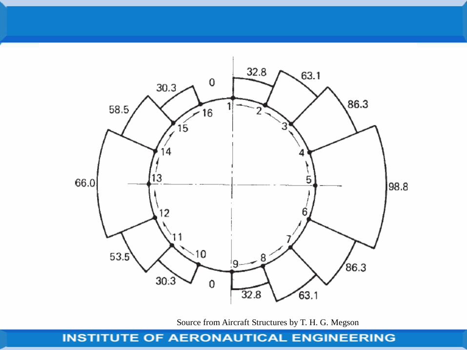
Source from Aircraft Structures by T. H. G. Megson
UNIT V
ANALYSIS OF FUSELAGE, WING AND LANDING GEAR
Wing spars and box beams
Established the basic theory for the analysis of open and closed section thin-walled beams subjected to bending, shear and torsional loads.
In addition, complex stringer stiffened sections could be idealized intosections more amenable to analysis.
Now extend this analysis to actual aircraft components including, wing sparsand box beams.
Investigation and analysis of fuselages, wings, frames and ribs, and considerthe effects of cut-outs in wings and fuselages.
Source from Aircraft Structures by T. H. G. Megson
Aircraft structural components are, complex, consisting usually of thin sheetsof metal stiffened by arrangements of stringers.
These structures are highly redundant and require some degree ofsimplification or idealization before they can be analysed.
The analysis presented here is therefore approximate and the degree ofaccuracy obtained depends on the number of simplifying assumptions made.
A further complication arises in that factors such as warping restraint,structural and loading discontinuities and shear lag significantly affect theanalysis,
Shall investigate these effects in some simple structural components.Source from Aircraft Structures by T. H. G. Megson
Generally, a high degree of accuracy can only be obtained by usingcomputer-based techniques such as the finite element method.
However, the simpler, quicker and cheaper approximate methods can beused to advantage in the preliminary stages of design when severalpossible structural alternatives are being investigated,
they also provide an insight into the physical behaviour of structures whichcomputer-based techniques do not.
Major aircraft structural components such as wings and fuselages areusually tapered along their lengths for greater structural efficiency.
Source from Aircraft Structures by T. H. G. Megson
Thus, wing sections are reduced both chordwise and in depth along the wingspan towards the tip and fuselage sections aft of the passenger cabin taper toprovide a more efficient aerodynamic and structural shape.
The analysis of open and closed section beams assumes that the beamsections are uniform.
The effect of taper on the prediction of direct stresses produced by bending isminimal if the taper is small and the section properties are calculated at theparticular section being considered,
Calculation of shear stresses in beam webs can be significantly affected bytaper.
Source from Aircraft Structures by T. H. G. Megson
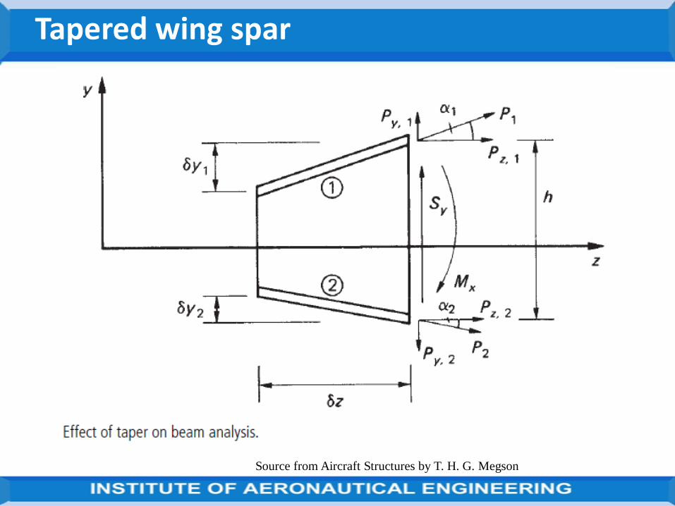
Tapered wing spar
Source from Aircraft Structures by T. H. G. Megson
Consider the simple case of wing spar beam, positioned in the yz plane andcomprising two flanges and a web: an elemental length δz of the beam isshown in Fig. above slide.
At the section z the beam is subjected to a positive bending moment Mx anda positive shear force Sy.
The bending moment resultants Pz,1 and Pz,2 are parallel to the z axis of thebeam.
For a beam in which the flanges are assumed to resist all the direct stresses,Pz,1 =Mx/h and Pz,2=−Mx/h.
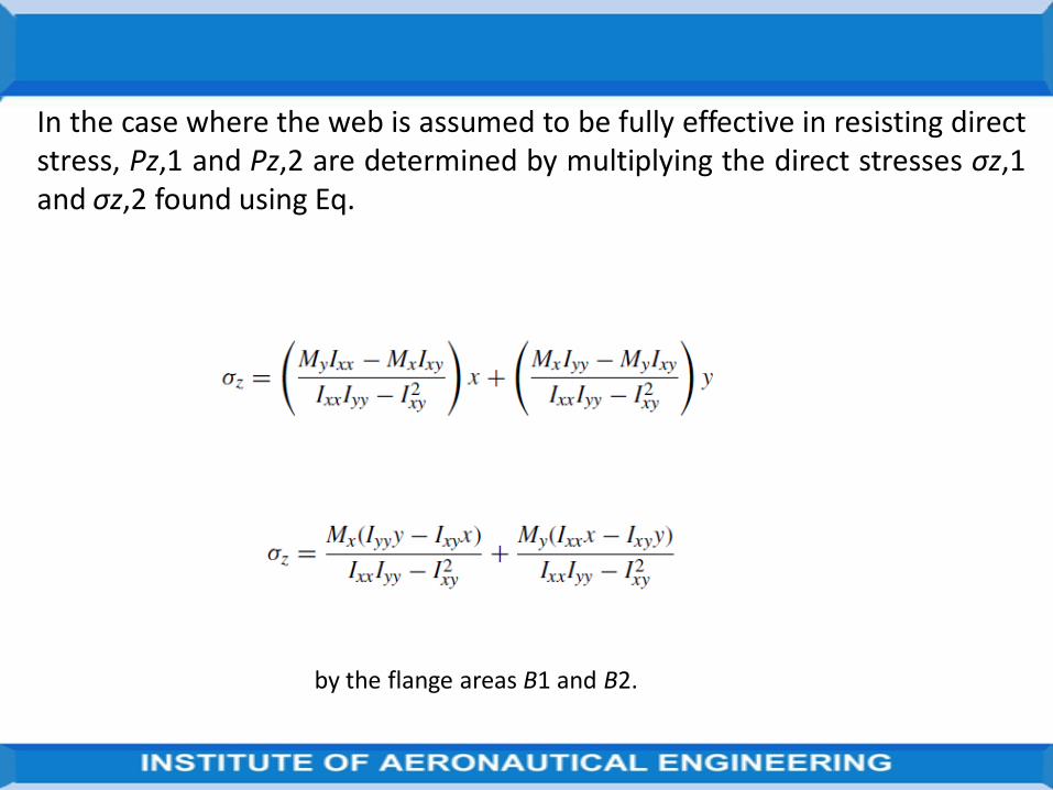
In the case where the web is assumed to be fully effective in resisting directstress, Pz,1 and Pz,2 are determined by multiplying the direct stresses σz,1and σz,2 found using Eq.
by the flange areas B1 and B2.
Pz,1 and Pz,2 are the components in the z direction of the axial loads P1 andP2 in the flanges.
These have components Py,1 and Py,2 parallel to the y axis given by
in which, for the direction of taper shown, δy2 is negative. The axial load in flange is given by
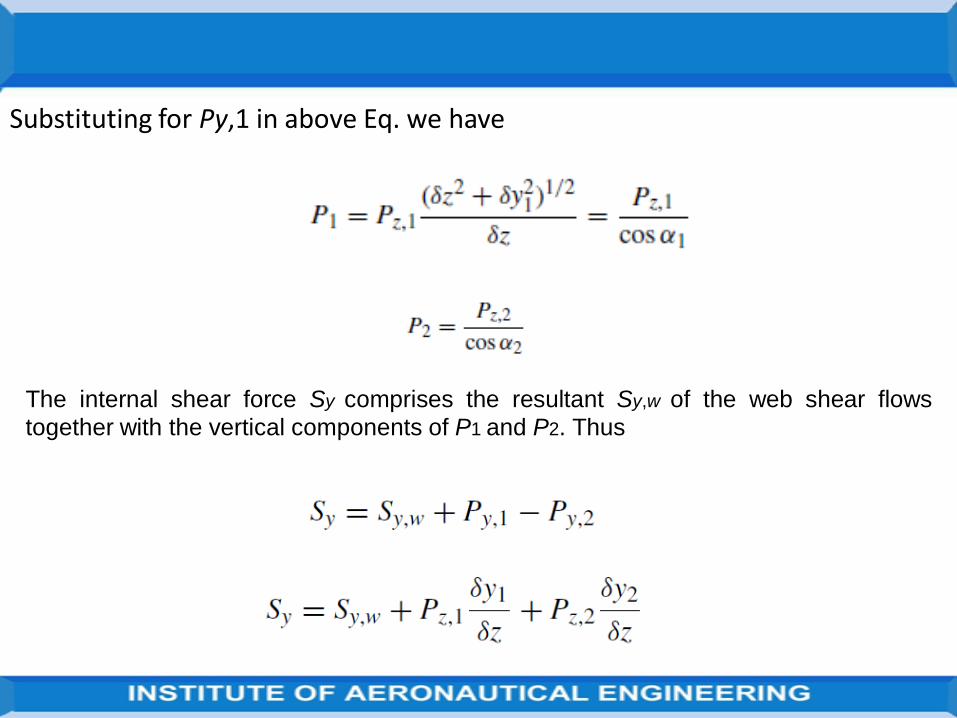
Substituting for Py,1 in above Eq. we have
The internal shear force Sy comprises the resultant Sy,w of the web shear flows
together with the vertical components of P1 and P2. Thus
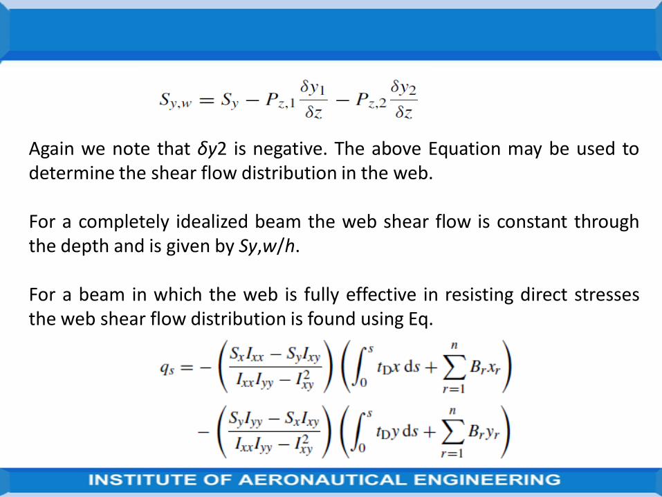
Again we note that δy2 is negative. The above Equation may be used todetermine the shear flow distribution in the web.
For a completely idealized beam the web shear flow is constant throughthe depth and is given by Sy,w/h.
For a beam in which the web is fully effective in resisting direct stressesthe web shear flow distribution is found using Eq.

Sy is replaced by Sy,w and which, for the beam would simplify to
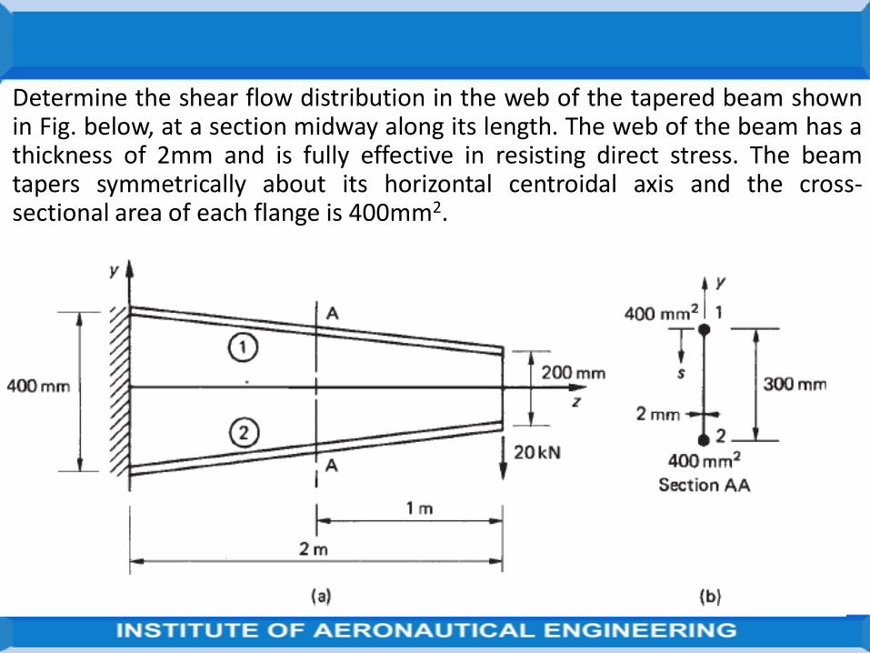
Determine the shear flow distribution in the web of the tapered beam shownin Fig. below, at a section midway along its length. The web of the beam has athickness of 2mm and is fully effective in resisting direct stress. The beamtapers symmetrically about its horizontal centroidal axis and the cross-sectional area of each flange is 400mm2.
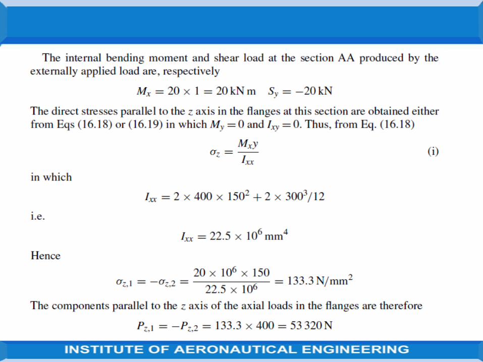
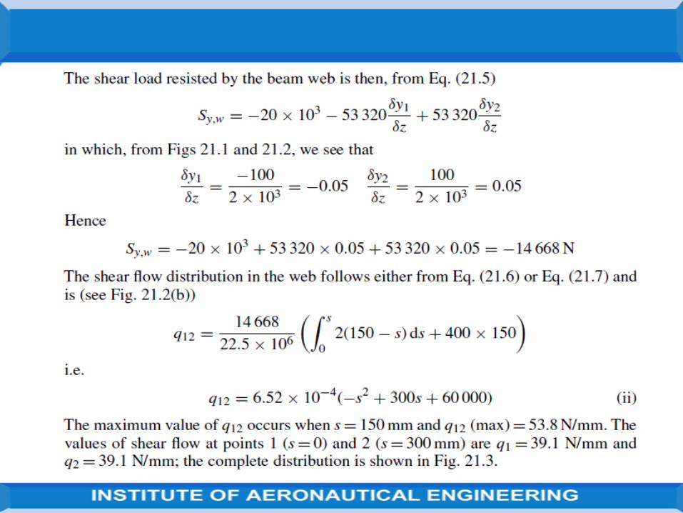
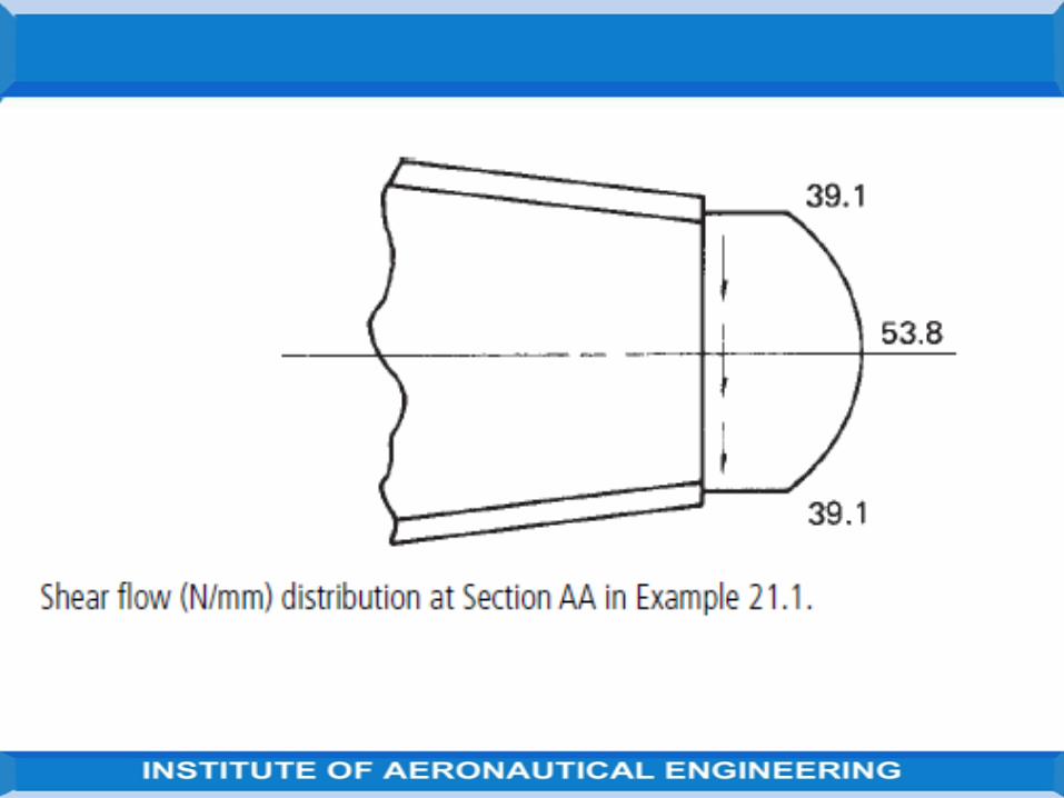
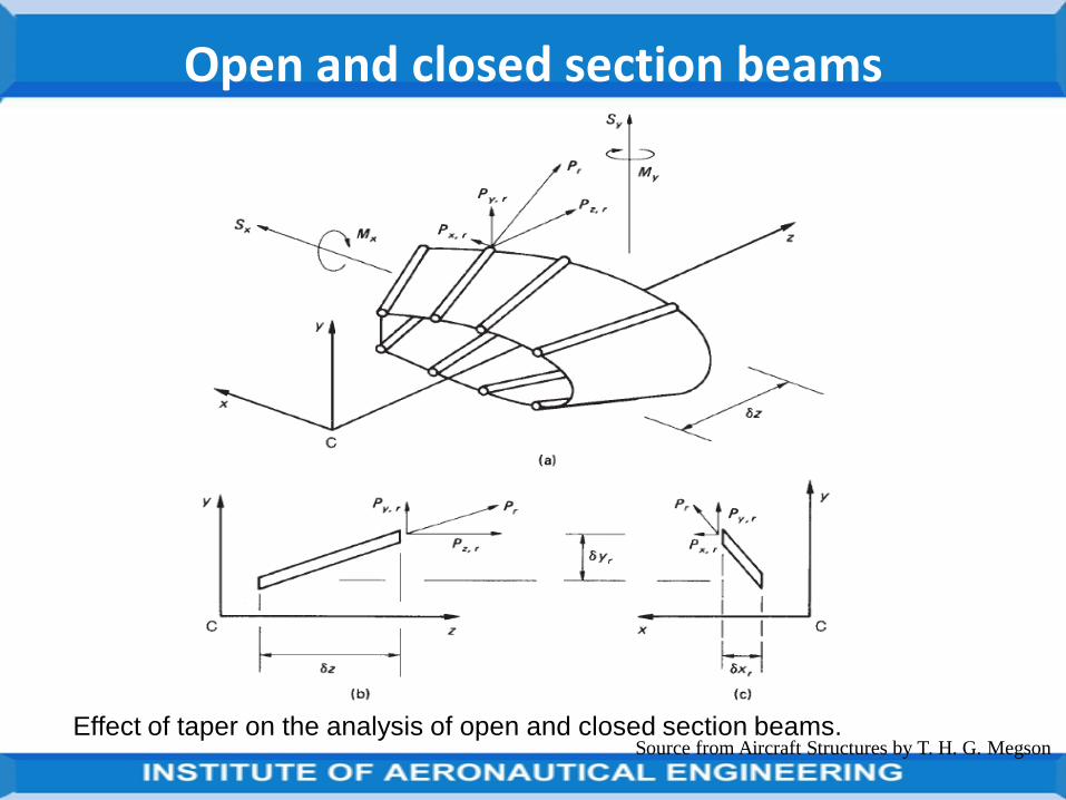
Open and closed section beams
Effect of taper on the analysis of open and closed section beams.Source from Aircraft Structures by T. H. G. Megson
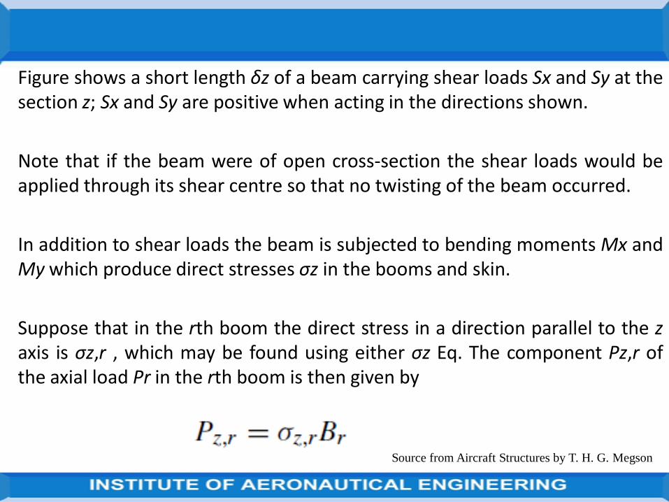
Figure shows a short length δz of a beam carrying shear loads Sx and Sy at thesection z; Sx and Sy are positive when acting in the directions shown.
Note that if the beam were of open cross-section the shear loads would beapplied through its shear centre so that no twisting of the beam occurred.
In addition to shear loads the beam is subjected to bending moments Mx andMy which produce direct stresses σz in the booms and skin.
Suppose that in the rth boom the direct stress in a direction parallel to the zaxis is σz,r , which may be found using either σz Eq. The component Pz,r ofthe axial load Pr in the rth boom is then given by
Source from Aircraft Structures by T. H. G. Megson
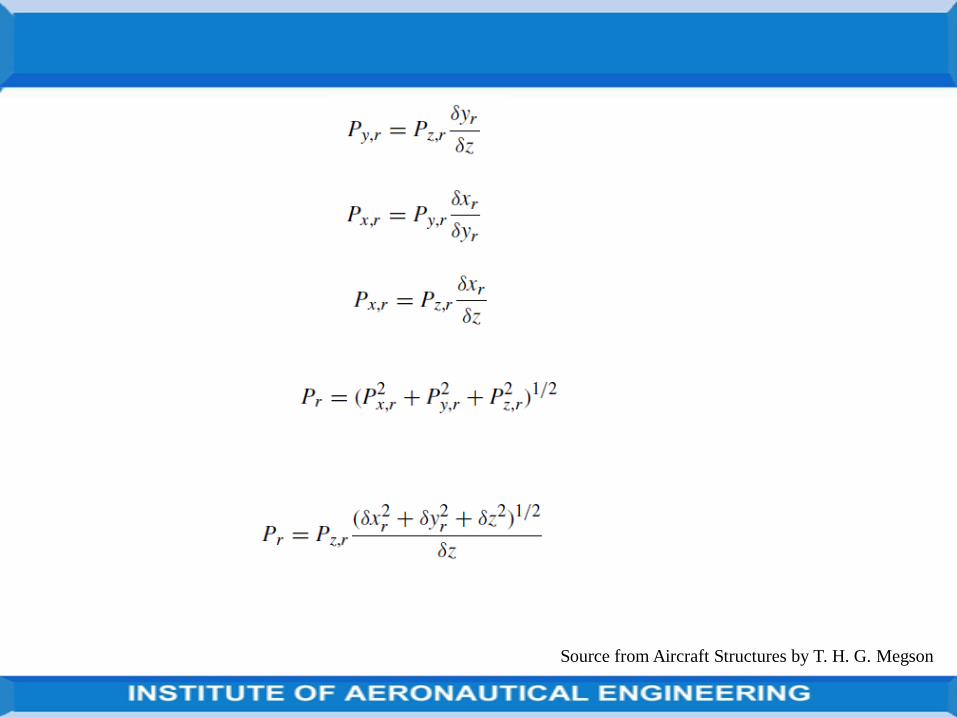
Source from Aircraft Structures by T. H. G. Megson
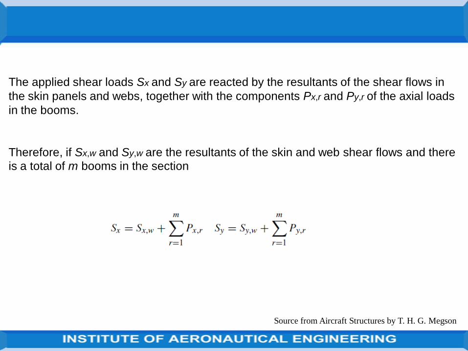
Source from Aircraft Structures by T. H. G. Megson
The applied shear loads Sx and Sy are reacted by the resultants of the shear flows in
the skin panels and webs, together with the components Px,r and Py,r of the axial loads
in the booms.
Therefore, if Sx,w and Sy,w are the resultants of the skin and web shear flows and there
is a total of m booms in the section
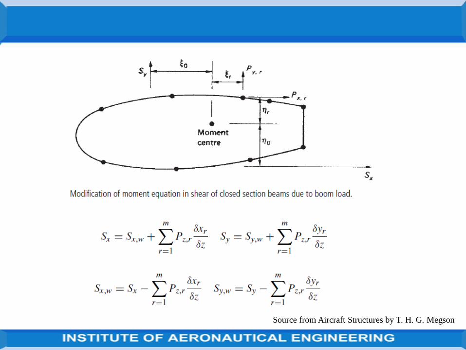
Source from Aircraft Structures by T. H. G. Megson
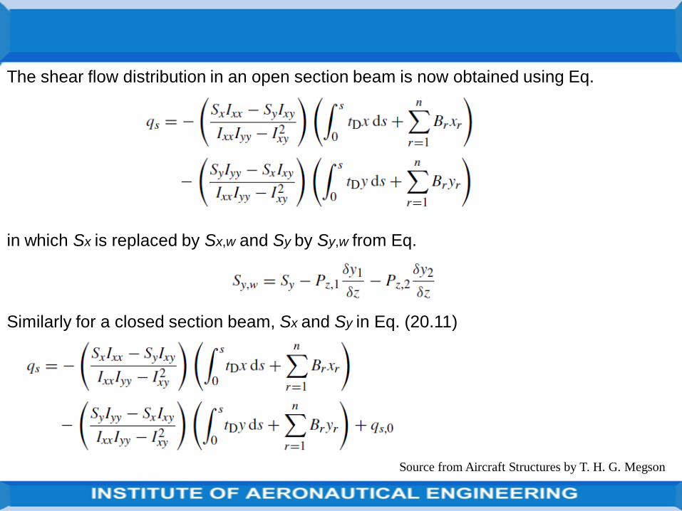
Source from Aircraft Structures by T. H. G. Megson
The shear flow distribution in an open section beam is now obtained using Eq.
in which Sx is replaced by Sx,w and Sy by Sy,w from Eq.
Similarly for a closed section beam, Sx and Sy in Eq. (20.11)
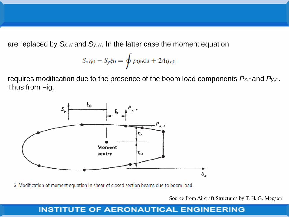
Source from Aircraft Structures by T. H. G. Megson
are replaced by Sx,w and Sy,w. In the latter case the moment equation
requires modification due to the presence of the boom load components Px,r and Py,r . Thus from Fig.
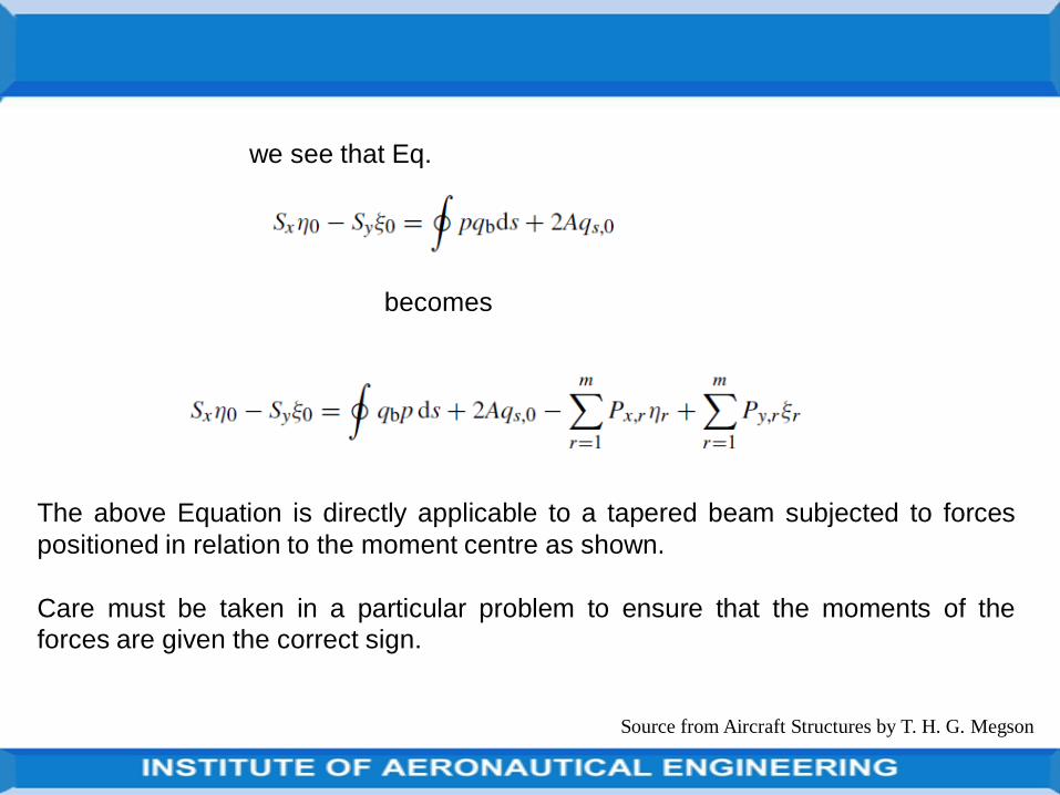
Source from Aircraft Structures by T. H. G. Megson
we see that Eq.
becomes
The above Equation is directly applicable to a tapered beam subjected to forces
positioned in relation to the moment centre as shown.
Care must be taken in a particular problem to ensure that the moments of the
forces are given the correct sign.
Source from Aircraft Structures by T. H. G. Megson
The calculation of shear flow distributions in beams having variable stringerareas is based on the alternative method for the calculation of shear flowdistributions described in previous Section and illustrated in the alternativesolution also.
The stringer loads Pz,1 and Pz,2 are calculated at two sections z1 and z2 ofthe beam a convenient distance apart.
We assume that the stringer load varies linearly along its length so that thechange in stringer load per unit length of beam is given by
The shear flow distribution follows as previously described.
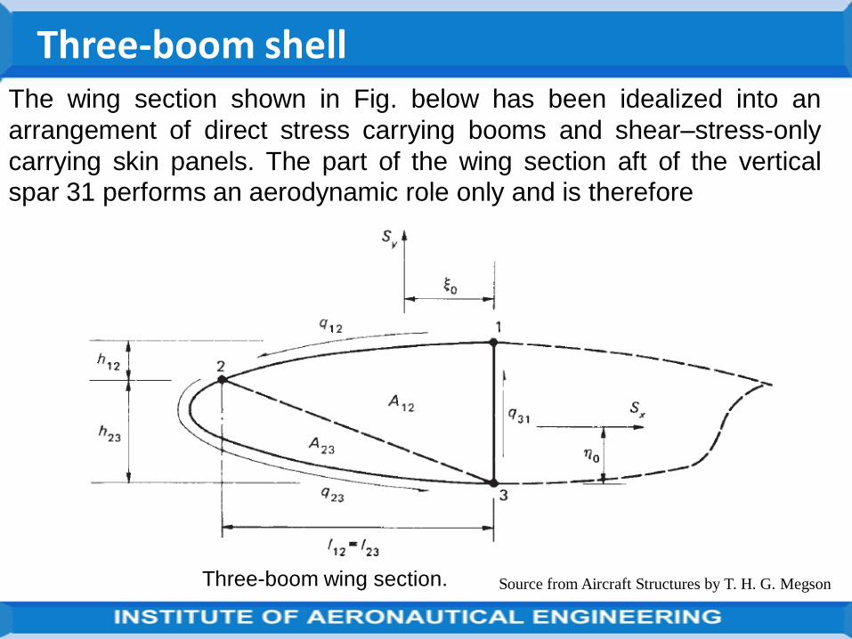
Source from Aircraft Structures by T. H. G. Megson
Three-boom shellThe wing section shown in Fig. below has been idealized into an
arrangement of direct stress carrying booms and shear–stress-only
carrying skin panels. The part of the wing section aft of the vertical
spar 31 performs an aerodynamic role only and is therefore
Three-boom wing section.
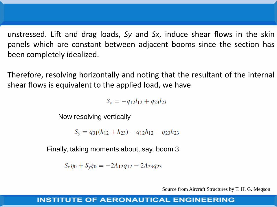
Source from Aircraft Structures by T. H. G. Megson
unstressed. Lift and drag loads, Sy and Sx, induce shear flows in the skinpanels which are constant between adjacent booms since the section hasbeen completely idealized.
Therefore, resolving horizontally and noting that the resultant of the internalshear flows is equivalent to the applied load, we have
Now resolving vertically
Finally, taking moments about, say, boom 3
Source from Aircraft Structures by T. H. G. Megson
In the above there are three unknown values of shear flow, q12, q23, q31and three equations of statical equilibrium. We conclude therefore that athree-boom idealized shell is statically determinate.
We shall return to the simple case of a three-boom wing section when weexamine the distributions of direct load and shear flows in wing ribs.
Meanwhile, we shall consider the bending, torsion and shear ofmulticellular wing sections.
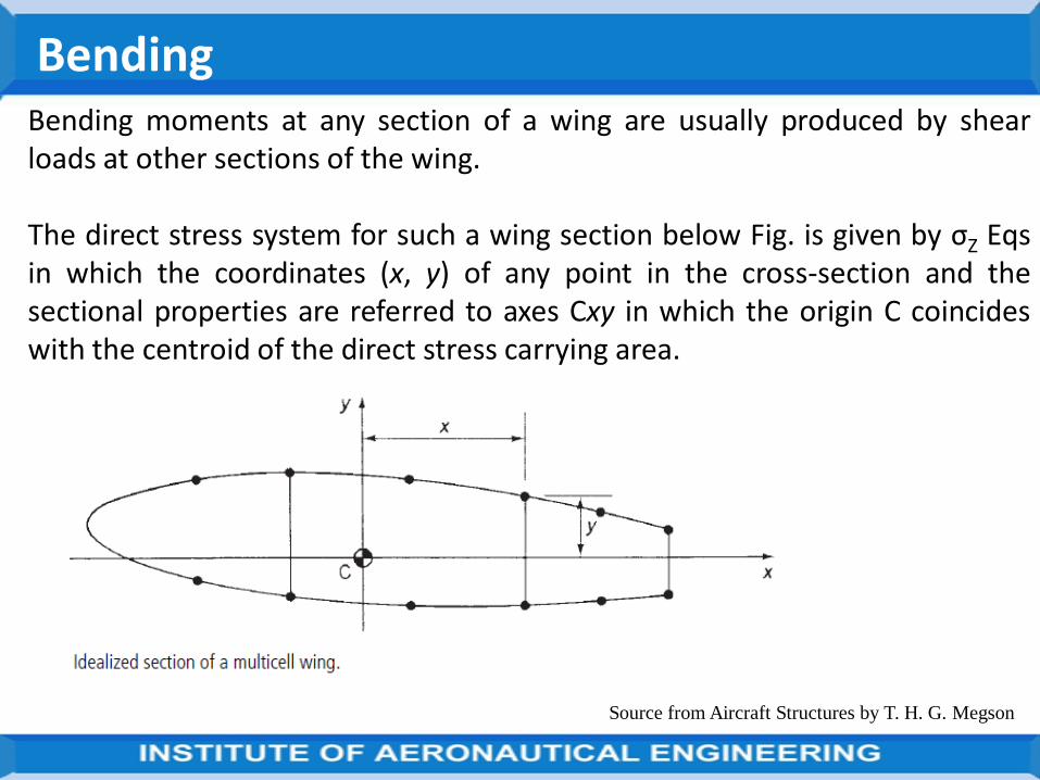
Source from Aircraft Structures by T. H. G. Megson
BendingBending moments at any section of a wing are usually produced by shearloads at other sections of the wing.
The direct stress system for such a wing section below Fig. is given by σZ Eqsin which the coordinates (x, y) of any point in the cross-section and thesectional properties are referred to axes Cxy in which the origin C coincideswith the centroid of the direct stress carrying area.
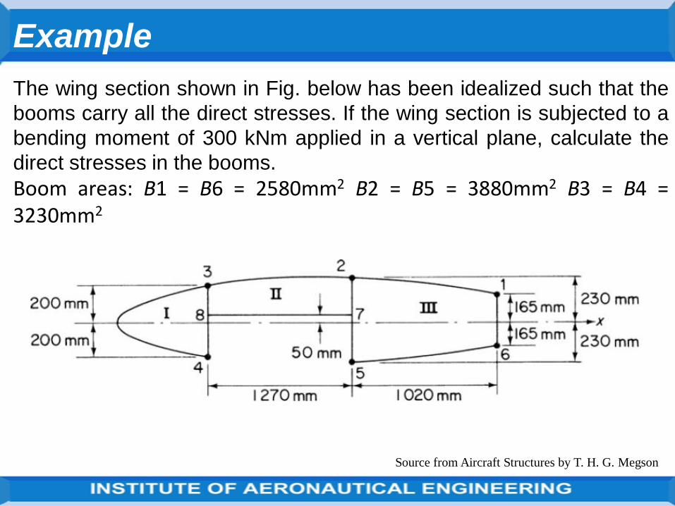
Source from Aircraft Structures by T. H. G. Megson
Example
The wing section shown in Fig. below has been idealized such that the
booms carry all the direct stresses. If the wing section is subjected to a
bending moment of 300 kNm applied in a vertical plane, calculate the
direct stresses in the booms.
Boom areas: B1 = B6 = 2580mm2 B2 = B5 = 3880mm2 B3 = B4 =3230mm2
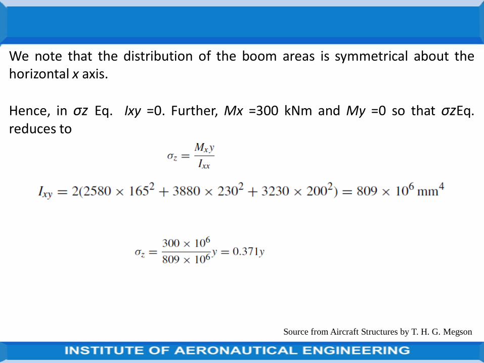
Source from Aircraft Structures by T. H. G. Megson
We note that the distribution of the boom areas is symmetrical about thehorizontal x axis.
Hence, in σz Eq. Ixy =0. Further, Mx =300 kNm and My =0 so that σzEq.reduces to
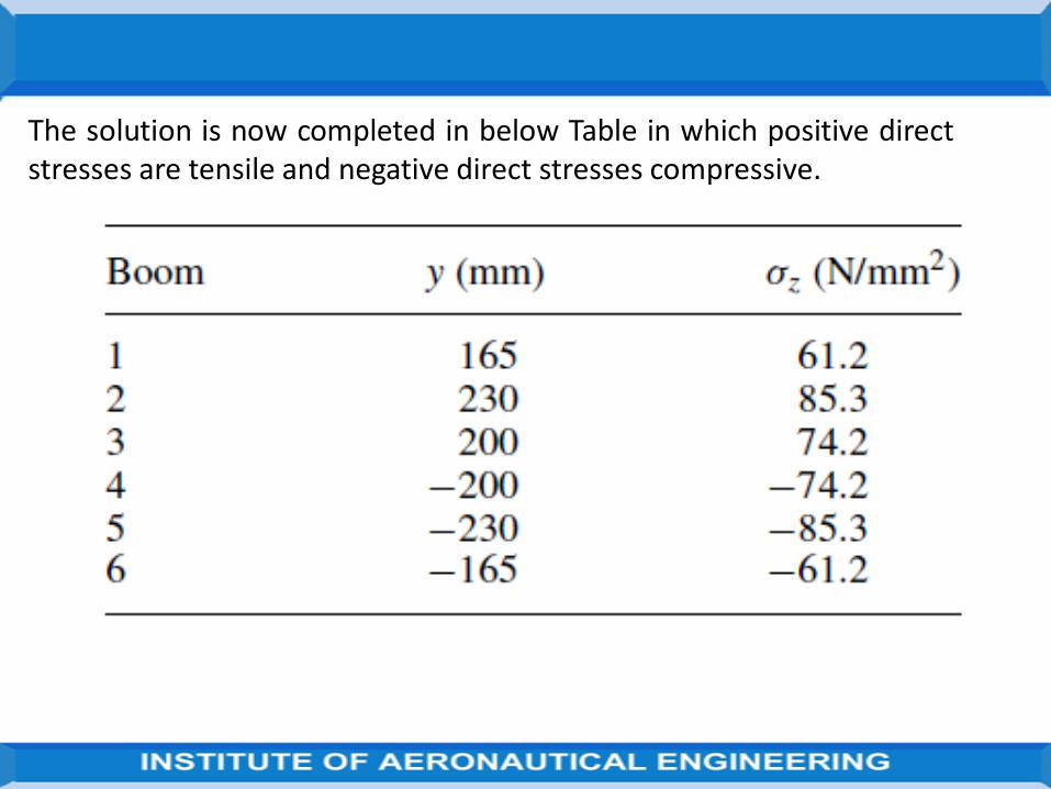
The solution is now completed in below Table in which positive directstresses are tensile and negative direct stresses compressive.
Source from Aircraft Structures by T. H. G. Megson
TorsionThe chord wise pressure distribution on an aerodynamic surface may berepresented by shear loads (lift and drag loads) acting through theaerodynamic centre together with a pitching moment M0.
This system of shear loads may be transferred to the shear centre of thesection in the form of shear loads Sx and Sy together with a torque T.
It is the pure torsion case that is considered here. In the analysis we assumethat no axial constraint effects are present and that the shape of the wingsection remains unchanged by the load application.
In the absence of axial constraint there is no development of direct stress in the wing section so that only shear stresses are present.
It follows that the presence of booms does not affect the analysis in the pure torsion case.
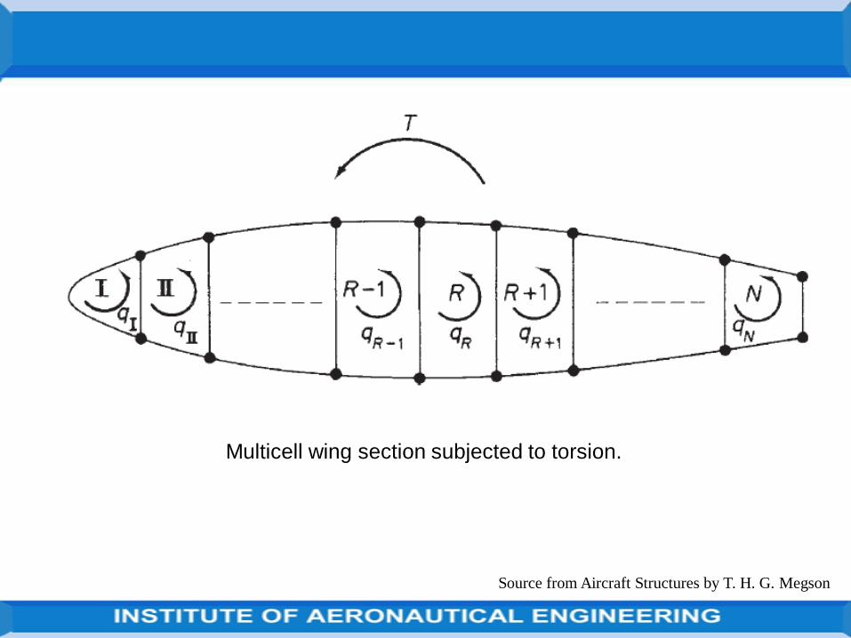
Source from Aircraft Structures by T. H. G. Megson
Multicell wing section subjected to torsion.
Source from Aircraft Structures by T. H. G. Megson
The wing section shown in Fig. 23.4 comprises N cells and carries a torque T which generates individual but unknown torques in each of the N cells.
Each cell therefore develops a constant shear flow qI, qII, . . . , qR, . . . , qN.
Source from Aircraft Structures by T. H. G. Megson
Deflections
Deflections of multi-cell wings may be calculated by the unit load method inan identical manner to that described in open and single cell beams.
Cut-outs in wings
Wings, as well as fuselages, have openings in their surfaces toaccommodate undercarriages, engine nacelles and weapons installations,etc.
In addition inspection panels are required at specific positions so that, asfor fuselages, the loads in adjacent portions of the wing structure aremodified.
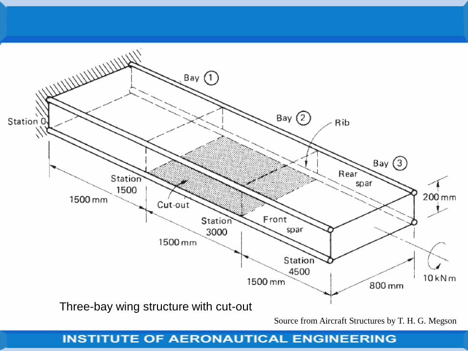
Source from Aircraft Structures by T. H. G. Megson
Three-bay wing structure with cut-out
In practice it is necessary to provide openings in these closed stiffenedshells for, for example, doors, cockpits, bomb bays, windows inpassenger cabins, etc.
These openings or ‘cut-outs’ produce discontinuities in the otherwisecontinuous shell structure so that loads are redistributed in the vicinityof the cut-out thereby affecting loads in the skin, stringers and frames.
Frequently these regions must be heavily reinforced resulting inunavoidable weight increases.
In some cases, for example door openings in passenger aircraft, it is notpossible to provide rigid fuselage frames on each side of the openingbecause the cabin space must not be restricted.
In such situations a rigid frame is placed around the opening to resist shearloads and to transmit loads from one side of the opening to the other.
The effects of smaller cut-outs, such as those required for rows of windows inpassenger aircraft, may be found approximately as follows.
Figure shows a fuselage panel provided with cut-outs for windows which arespaced a distance l apart.
The panel is subjected to an average shear flow qav which would be the valueof the shear flow in the panel without cut-outs.
Considering a horizontal length of the panel through the cut-outs we see that
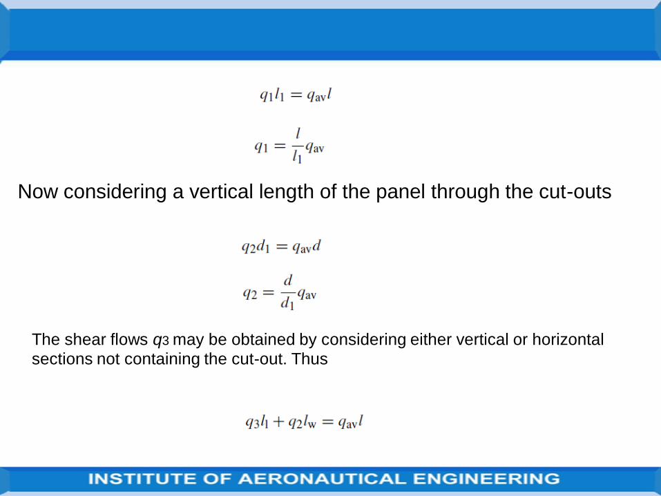
Now considering a vertical length of the panel through the cut-outs
The shear flows q3 may be obtained by considering either vertical or horizontal
sections not containing the cut-out. Thus
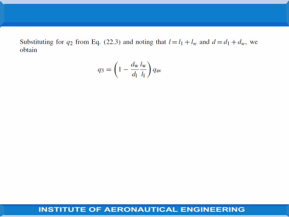
Source from Aircraft Structures by T. H. G. Megson
Aircraft are constructed primarily from thin metal skins which are capable ofresisting in-plane tension and shear loads but buckle under comparatively lowvalues of in-plane compressive loads.
The skins are therefore stiffened by longitudinal stringers which resist the in-plane compressive loads and, at the same time, resist small distributed loadsnormal to the plane of the skin.
The effective length in compression of the stringers is reduced, in the case offuselages, by transverse frames or bulkheads or, in the case of wings, by ribs.
In addition, the frames and ribs resist concentrated loads in transverse planesand transmit them to the stringers and the plane of the skin.
Thus, cantilever wings may be bolted to fuselage frames at the spar caps whileundercarriage loads are transmitted to the wing through spar and ribattachment points.
Fuselage frames and wing ribs
Source from Aircraft Structures by T. H. G. Megson
Principles of stiffener/web construction
Generally, frames and ribs are themselves fabricated from thin sheets ofmetal and therefore require stiffening members to distribute theconcentrated loads to the thin webs.
If the load is applied in the plane of a web the stiffeners must be alignedwith the direction of the load.
Alternatively, if this is not possible, the load should be applied at theintersection of two stiffeners so that each stiffener resists the component ofload in its direction.
Source from Aircraft Structures by T. H. G. Megson
A cantilever beam Fig. below carries concentrated loads as shown. Calculatethe distribution of stiffener loads and the shear flow distribution in the webpanels assuming that the latter are effective only in shear.
We note that stiffeners HKD and JK are required at the point of application ofthe 4000N load to resist its vertical and horizontal components.
A further transverse stiffener GJC is positioned at the unloaded end J of thestiffener JK since stress concentrations are produced if a stiffener ends in thecentre of a web panel.
We note also that the web panels are only effective in shear so that the shearflow is constant throughout a particular web panel; the assumed directions ofthe shear flows are shown in Fig.
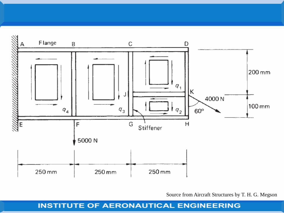
Source from Aircraft Structures by T. H. G. Megson

Source from Aircraft Structures by T. H. G. Megson
From the equilibrium of stiffener JK we have
(q1 − q2) × 250 = 4000 sin 60◦ = 3464.1N
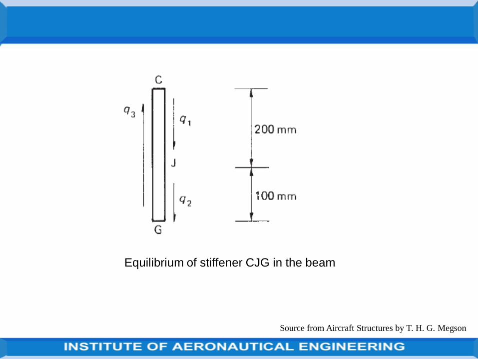
Source from Aircraft Structures by T. H. G. Megson
Equilibrium of stiffener CJG in the beam
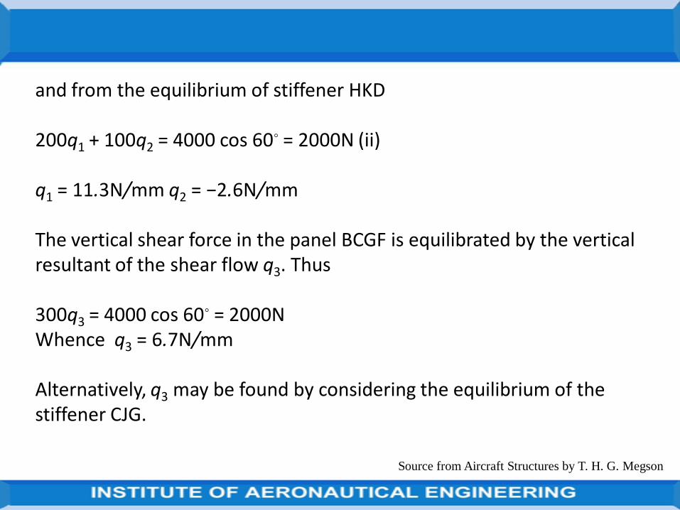
Source from Aircraft Structures by T. H. G. Megson
and from the equilibrium of stiffener HKD
200q1 + 100q2 = 4000 cos 60◦ = 2000N (ii)
q1 = 11.3N/mm q2 = −2.6N/mm
The vertical shear force in the panel BCGF is equilibrated by the vertical resultant of the shear flow q3. Thus
300q3 = 4000 cos 60◦ = 2000NWhence q3 = 6.7N/mm
Alternatively, q3 may be found by considering the equilibrium of the stiffener CJG.
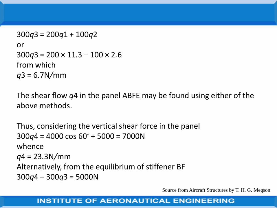
Source from Aircraft Structures by T. H. G. Megson
300q3 = 200q1 + 100q2or300q3 = 200 × 11.3 − 100 × 2.6from whichq3 = 6.7N/mm
The shear flow q4 in the panel ABFE may be found using either of the above methods.
Thus, considering the vertical shear force in the panel300q4 = 4000 cos 60◦ + 5000 = 7000Nwhenceq4 = 23.3N/mmAlternatively, from the equilibrium of stiffener BF300q4 − 300q3 = 5000N
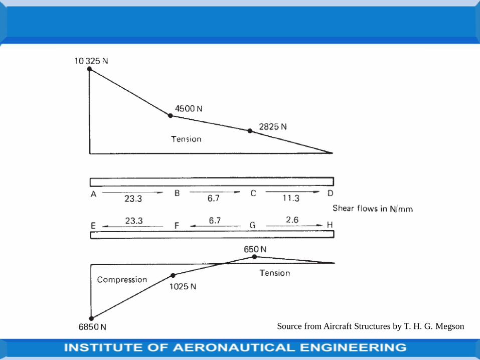
Source from Aircraft Structures by T. H. G. Megson
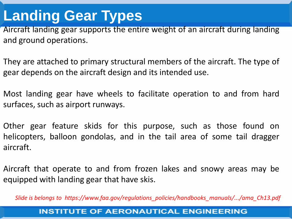
Landing Gear TypesAircraft landing gear supports the entire weight of an aircraft during landingand ground operations.
They are attached to primary structural members of the aircraft. The type ofgear depends on the aircraft design and its intended use.
Most landing gear have wheels to facilitate operation to and from hardsurfaces, such as airport runways.
Other gear feature skids for this purpose, such as those found onhelicopters, balloon gondolas, and in the tail area of some tail draggeraircraft.
Aircraft that operate to and from frozen lakes and snowy areas may beequipped with landing gear that have skis.
Slide is belongs to https://www.faa.gov/regulations_policies/handbooks_manuals/.../ama_Ch13.pdf
Aircraft that operate to and from the surface of water have pontoon-typelanding gear.
Regardless of the type of landing gear utilized, shock absorbing equipment,brakes, retraction mechanisms, controls, warning devices, cowling, fairings,and structural members necessary to attach the gear to the aircraft areconsidered parts of the landing gear system.
Landing Gear Arrangement
Three basic arrangements of landing gear are used: tail wheel type landinggear (also known as conventional gear), tandem landing gear, and tricycle-type landing gear.
Slide is belongs to https://www.faa.gov/regulations_policies/handbooks_manuals/.../ama_Ch13.pdf
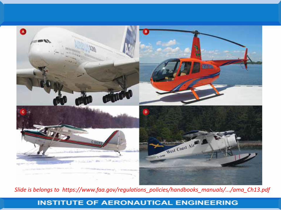
Slide is belongs to https://www.faa.gov/regulations_policies/handbooks_manuals/.../ama_Ch13.pdf
Slide is belongs to https://www.faa.gov/regulations_policies/handbooks_manuals/.../ama_Ch13.pdf
Tail Wheel-Type Landing Gear
Tail wheel-type landing gear is also known as conventional gear becausemany early aircraft use this type of arrangement.
The main gear are located forward of the center of gravity, causing the tail torequire support from a third wheel assembly.
A few early aircraft designs use a skid rather than a tail wheel. This helps slowthe aircraft upon landing and provides directional stability.
The resulting angle of the aircraft fuselage, when fitted with conventionalgear, allows the use of a long propeller that compensates for older,underpowered engine design.

Slide is belongs to https://www.faa.gov/regulations_policies/handbooks_manuals/.../ama_Ch13.pdf
The increased clearance of the forward fuselage offered by tail wheel-typelanding gear is also advantageous when operating in and out of non-pavedrunways.
Today, aircraft are manufactured with conventional gear for this reason andfor the weight savings accompanying the relatively light tail wheel assembly.
Slide is belongs to https://www.faa.gov/regulations_policies/handbooks_manuals/.../ama_Ch13.pdf
Tandem Landing GearFew aircraft are designed with tandem landing gear. As the name implies, thistype of landing gear has the main gear and tail gear aligned on the longitudinalaxis of the aircraft.
Sailplanes commonly use tandem gear, although many only have one actualgear forward on the fuselage with a skid under the tail.
A few military bombers, such as the B-47 and the B-52, have tandem gear, asdoes the U2 spy plane.
The VTOL Harrier has tandem gear but uses small outrigger gear under thewings for support.
Generally, placing the gear only under the fuselage facilitates the use of veryflexible wings.

Slide is belongs to https://www.faa.gov/regulations_policies/handbooks_manuals/.../ama_Ch13.pdf
Slide is belongs to https://www.faa.gov/regulations_policies/handbooks_manuals/.../ama_Ch13.pdf
Tricycle-Type Landing Gear
The most commonly used landing gear arrangement is the tricycle-typelanding gear. It is comprised of main gear and nose gear. [Figure 13-6]
Tricycle-type landing gear is used on large and small aircraft with thefollowing benefits:
1. Allows more forceful application of the brakes without nosing over whenbraking, which enables higher landing speeds.2. Provides better visibility from the flight deck, especially during landingand ground maneuvering.3. Prevents ground-looping of the aircraft. Since the aircraft center ofgravity is forward of the main gear, forces acting on the center of gravitytend to keep the aircraft moving forward rather than looping, such as witha tail wheel-type landing gear.
Slide is belongs to https://www.faa.gov/regulations_policies/handbooks_manuals/.../ama_Ch13.pdf
Thank You
ALL THE BEST
Related Documents