IT 10 061 Examensarbete 30 hp November 2010 Analysis Application for H.264 Video Encoding Ying Wang Institutionen för informationsteknologi Department of Information Technology

Welcome message from author
This document is posted to help you gain knowledge. Please leave a comment to let me know what you think about it! Share it to your friends and learn new things together.
Transcript
IT 10 061
Examensarbete 30 hpNovember 2010
Analysis Application for H.264 Video Encoding
Ying Wang
Institutionen för informationsteknologiDepartment of Information Technology

Teknisk- naturvetenskaplig fakultet UTH-enheten Besöksadress: Ångströmlaboratoriet Lägerhyddsvägen 1 Hus 4, Plan 0 Postadress: Box 536 751 21 Uppsala Telefon: 018 – 471 30 03 Telefax: 018 – 471 30 00 Hemsida: http://www.teknat.uu.se/student
Abstract
Analysis Application for H.264 Video Encoding
Ying Wang
A video analysis application ERANA264(Ericsson Research h.264 video ANalysis Application) is developed in this project. Erana264 is a tool that analyzes H.264 encoded video bitstreams, extracts the encoding information and parameters, analyzes them in different stages and displays the results in a user friendly way. The intention is that such an application would be used during development and testing of video codecs. The work is implemented on top of existing H.264 encoder/decoder source code (C/C++) developed at Ericsson Research.
Erana264 consists of three layers. The first layer is the H.264 decoder previously developed in Ericsson Research. By using the decoder APIs, the information is extracted from the bitstream and is sent to the higher layers. The second layer visualizes the different decoding stages, uses overlay to display some macro block and picture level information and provides a set of play back functions. The third layer analyzes and presents the statistics of prominent parameters in video compression process, such as video quality measurements, motion vector distribution, picture bit distribution etc.
Key words: H.264, Video compression, Bitstream analysis, Video encoding
Tryckt av: Reprocentralen ITCIT10061Examinator: Anders JanssonÄmnesgranskare: Cris LuengoHandledare: Zhuangfei Wu and Clinton Priddle

Acknowledgements
Fist of all, I am heartily thankful to my supervisors, Fred Wu and ClintonPriddle, whose encouragement, supervision and support from the preliminaryto the concluding level enabled me to develop an understanding of the subject.I am grateful to Rickard Sjoberg, not only for his previous delicated work onEricsson Research’s internal H.264 CODEC which is a essential basis of thisproject, but also for his continuous guidance and support, throughout the wholeperiod of the thesis.
It is an honor for me to have prof. Cris Luengo at Uppsala University as myreviewer, many thanks for his trust and suggestions on the thesis report.
I owe my deepest gratitude to Per Frojdh, the manager of the visual group foroffering me the work opportunity and kindly help. I would also like to thank allthe other members in the multimedia technology group, specially Per Boussardand Torbjorn Einarsson, for their valuable suggestions and contributing to anice working environment.
And finally never enough thanks to my parents and friends for their encour-agement and support throughout all my studies at University.
YingJune, 2010
III

Contents
1 Introduction 11.1 Purpose . . . . . . . . . . . . . . . . . . . . . . . . . . . . . . . . 11.2 The structure of this thesis . . . . . . . . . . . . . . . . . . . . . 2
2 Background 32.1 Video Compression . . . . . . . . . . . . . . . . . . . . . . . . . . 3
2.1.1 Temporal Model . . . . . . . . . . . . . . . . . . . . . . . 42.1.2 Image Model . . . . . . . . . . . . . . . . . . . . . . . . . 42.1.3 Entropy Coder . . . . . . . . . . . . . . . . . . . . . . . . 7
2.2 H.264 Standard . . . . . . . . . . . . . . . . . . . . . . . . . . . . 72.2.1 H.264 CODEC . . . . . . . . . . . . . . . . . . . . . . . . 7
2.3 Video Analysis . . . . . . . . . . . . . . . . . . . . . . . . . . . . 82.3.1 Important coding parameters . . . . . . . . . . . . . . . . 9
3 System Design 123.1 Requirements . . . . . . . . . . . . . . . . . . . . . . . . . . . . . 123.2 Development environment and programming languages . . . . . . 133.3 Development Process . . . . . . . . . . . . . . . . . . . . . . . . . 13
3.3.1 Collect user requirements . . . . . . . . . . . . . . . . . . 133.3.2 Implementation . . . . . . . . . . . . . . . . . . . . . . . . 143.3.3 Simulation utilizing and Fine-tuning . . . . . . . . . . . . 14
3.4 System Structure . . . . . . . . . . . . . . . . . . . . . . . . . . . 14
4 Erana264 Functionality 164.1 Erana264 Overview . . . . . . . . . . . . . . . . . . . . . . . . . . 174.2 Main Features . . . . . . . . . . . . . . . . . . . . . . . . . . . . . 17
4.2.1 Full display mode . . . . . . . . . . . . . . . . . . . . . . . 184.2.2 Picture display in different decoding stages . . . . . . . . 194.2.3 Picture general information . . . . . . . . . . . . . . . . . 194.2.4 Summary statistics . . . . . . . . . . . . . . . . . . . . . . 194.2.5 MB insight analysis . . . . . . . . . . . . . . . . . . . . . 214.2.6 Overlay display . . . . . . . . . . . . . . . . . . . . . . . . 224.2.7 Visualize prominent parameters . . . . . . . . . . . . . . . 234.2.8 Import and Export . . . . . . . . . . . . . . . . . . . . . . 24
V
5 Experiments 265.1 Comparison between different encoding parameter with same video
sequence . . . . . . . . . . . . . . . . . . . . . . . . . . . . . . . . 265.1.1 Sequence Statistics . . . . . . . . . . . . . . . . . . . . . . 275.1.2 Macro block Prediction Mode . . . . . . . . . . . . . . . . 285.1.3 PSNR . . . . . . . . . . . . . . . . . . . . . . . . . . . . . 30
5.2 Comparison between different video sequence with same encodingparameters . . . . . . . . . . . . . . . . . . . . . . . . . . . . . . 315.2.1 Overview of the sample video sequence . . . . . . . . . . . 315.2.2 Motion Vector . . . . . . . . . . . . . . . . . . . . . . . . 355.2.3 PSNR . . . . . . . . . . . . . . . . . . . . . . . . . . . . . 365.2.4 Macro block Prediction Mode . . . . . . . . . . . . . . . . 38
6 Conclusions and Further development 416.1 Conclusions . . . . . . . . . . . . . . . . . . . . . . . . . . . . . . 416.2 Further development . . . . . . . . . . . . . . . . . . . . . . . . . 41
VI
Chapter 1
Introduction
Despite the rapidly improving computing and communications capabilities, thedemand of efficient and high quality digital video is still drastically increasingin video conferencing, high definition television, online stream video and manyother areas. Since the transmission or storage of each single bit is an increasein cost, researchers from companies and universities put a lot of efforts on de-veloping more efficient video compression technology, to get high quality videowhile keeping coded bitstream size small. Video compression has played an im-portant role in the areas of telecommunication and multimedia systems. Theprimary goal of video compression is to reduce the amount of information thathas to be transmitted or stored without reducing its subjective quality. Withthe intention of helping to develop and optimize the latest video compressionCODECs, a video analysis application is developed in this project.
1.1 Purpose
The new video coding standard H.264 (Advanced Video Coding, AVC) hasbecome the leading standard for new video services such as HDTV, Bluray andmobile TV. Although decoding is standardized, the encoding process is fullyopen as long as the coded bitstream conforms to the decoder. How a videosequence is coded varies among different encoders. A state-of-the art HDTVencoder, for example, will use that freedom to spend fewer bits on areas thattolerate coding distortion and spend more bits on critical parts.
H.264 standard includes many processes and there can be huge perfor-mance difference among standards-compliant encoders and decoders. In orderto achieve good performance, careful design and careful choice of coding param-eters are required. A video analysis application ERANA264(Ericsson Researchh.264 video ANalysis Application) is developed in this project,to help to opti-mize the CODEC and choose the proper parameters. Erana264 is a tool thatanalyzes H.264 encoded video bitstreams, extracts the encoding information andparameters, analyzes this information and displays the results in a visual anduser friendly way. The intention is that such an application would be used dur-ing development and testing of video codecs. The work is implemented on topof existing H.264 encoder/decoder source code (C/C++) developed at EricssonResearch.
1
1.2 The structure of this thesis
Chapter 2 introduces the basic concepts about video compression, H.264 stan-dard and how video analysis application works.Chapter 3 discusses about the system requirements, development process andgive an overview of this video analyze application.Chapter 4 introduces the main features and most important functions in thisapplication.Chapter 5 analyzes some representive video sequences in different perspectives.Chapter 6 concludes this thesis and provides some ideas about possible futureworks.
2
Chapter 2
Background
2.1 Video Compression
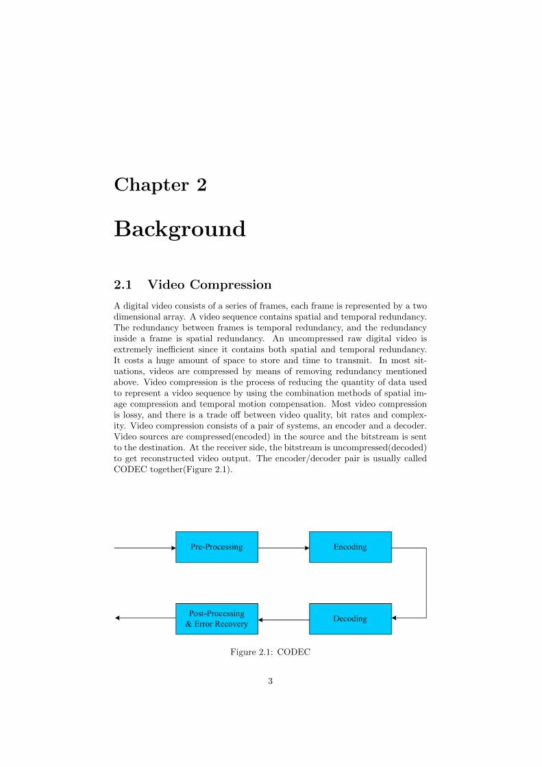
A digital video consists of a series of frames, each frame is represented by a twodimensional array. A video sequence contains spatial and temporal redundancy.The redundancy between frames is temporal redundancy, and the redundancyinside a frame is spatial redundancy. An uncompressed raw digital video isextremely inefficient since it contains both spatial and temporal redundancy.It costs a huge amount of space to store and time to transmit. In most sit-uations, videos are compressed by means of removing redundancy mentionedabove. Video compression is the process of reducing the quantity of data usedto represent a video sequence by using the combination methods of spatial im-age compression and temporal motion compensation. Most video compressionis lossy, and there is a trade off between video quality, bit rates and complex-ity. Video compression consists of a pair of systems, an encoder and a decoder.Video sources are compressed(encoded) in the source and the bitstream is sentto the destination. At the receiver side, the bitstream is uncompressed(decoded)to get reconstructed video output. The encoder/decoder pair is usually calledCODEC together(Figure 2.1).
Figure 2.1: CODEC
3
2.1.1 Temporal Model
In an uncompressed video sequence, there is always a lot of redundancy in-formation between frames. A temporal model is typically used to reduce theredundancy by predicting the difference between the coded frames and the framebeing coded. In this way, by sending the residual(difference) frames instead ofthe whole frame, temporal redundancy can be greatly reduced. The better theprediction is, the more redundancy information can be eliminated.
Motion compensation is introduced for the purpose of reducing temporalredundancy. H.264 standard uses a block-based motion estimation and com-pensation algorithm. Every frame in the sequence is divided to 16 × 16 pixelblocks called macro blocks. Macro blocks are the basic unit in the motioncompensation algorithm in H.264 standard and many other standards. Motionestimation algorithm typically tries to find the best matching 16 × 16 regioninside a reference frame to the current macro block. Once a region is found, thealgorithm calculates the distance from the current macro block to the referenceregion and gets a motion vector that represents the distance. The selected “BestMatch” region will be subtracted from the current macro block to get a residualmacro block, the residual will be encoded and transmitted together with themotion vector. The receiver uses the residual and motion vector to reconstructthe original macro block.
2.1.2 Image Model
Image Model is used to decorrelate image data and convert it in a form thatcan be efficiently compressed. Image models usually have three parts: trans-formation, quantization and reordering. The purpose of transformation is todecorrelate and compact the data, quantization is used to reduce the precisionof the data and through reordering we can put all significant values together.
Predictive Image Coding
Motion compensation is an example of predictive image coding. The encodermakes a prediction based on the previous frame and subtracts the predictionfrom the current image to get a residual image. The residual image containsless information and can be compressed in less bits. Another type of predictionis prediction based on previous transmitted samples in the same frame.
Transform Coding
The purpose of transform coding is to convert the residual data from the spa-tial domain to frequency domain. There are many transforms that can be usedin image and video compression, and all of them can be put into two types:block-based and image-based. The Karhunen-Loeve Transform(KLT)[3], Singu-lar Value Decomposition(SVD)[4] and the Discrete Cosine Transform(DCT)[5]are block based. The Discrete Wavelet Transform (DWT) is image based.Image-based transformation has better performance but meanwhile has higherrequirements for memory(it transforms the whole image as a single unit) anddoes not cooperate well with block based motion compensation. In the H.264standard, block-based transforms are used and it will be discussed in the laterchapters.
4
Quantization
Quantization is the process of mapping a continuous range of values to a reducedrange of values. The input to a quantizer is the original data, and the output isa number among a finite range of values. Obviously, this process is lossy and cannot be reversed. A good quantizer is a quantizer which represents the originaldata with minimum loss and distortion. There are two kinds of quantization:Scalar Quantization and Vector Quantization.
Scalar quantization A scalar quantization maps an input signal with a rangeof values X to a quantized signal with a reduced range of values Y, every inputsample is processed separately. Scalar Quantization is used in H.264 standard.A general example of a uniform quantizer:
FQ = round(X
QP) (2.1)
Y = FQ ·QP (2.2)
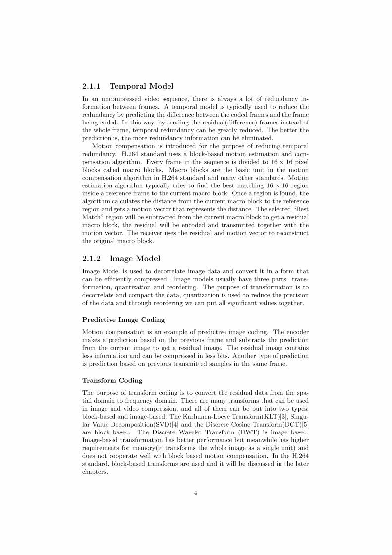
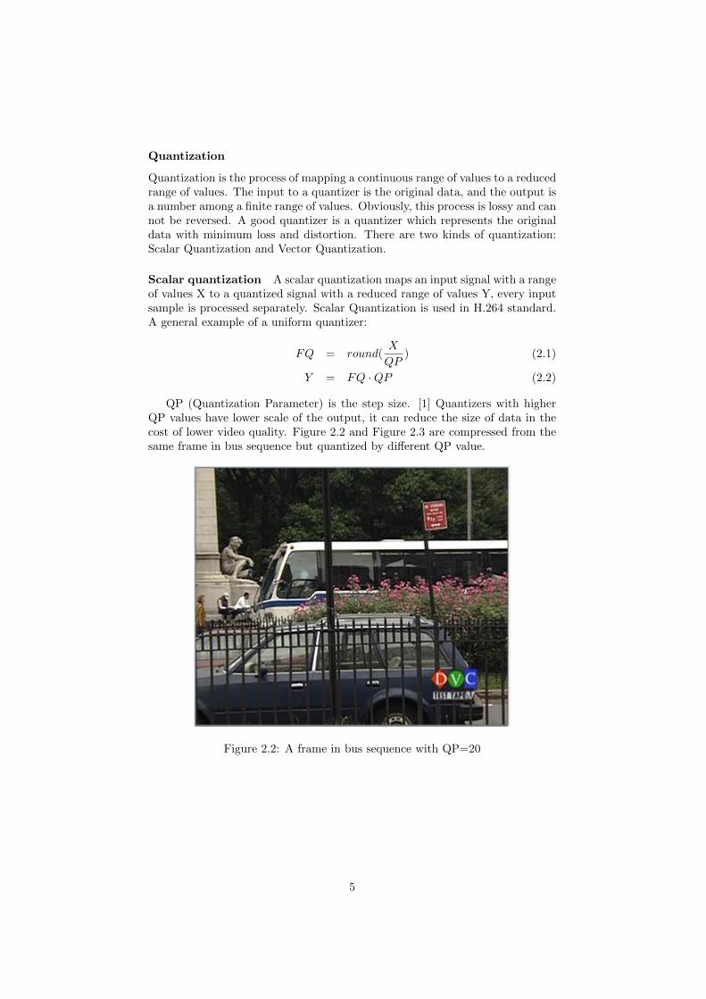
QP (Quantization Parameter) is the step size. [1] Quantizers with higherQP values have lower scale of the output, it can reduce the size of data in thecost of lower video quality. Figure 2.2 and Figure 2.3 are compressed from thesame frame in bus sequence but quantized by different QP value.
Figure 2.2: A frame in bus sequence with QP=20
5
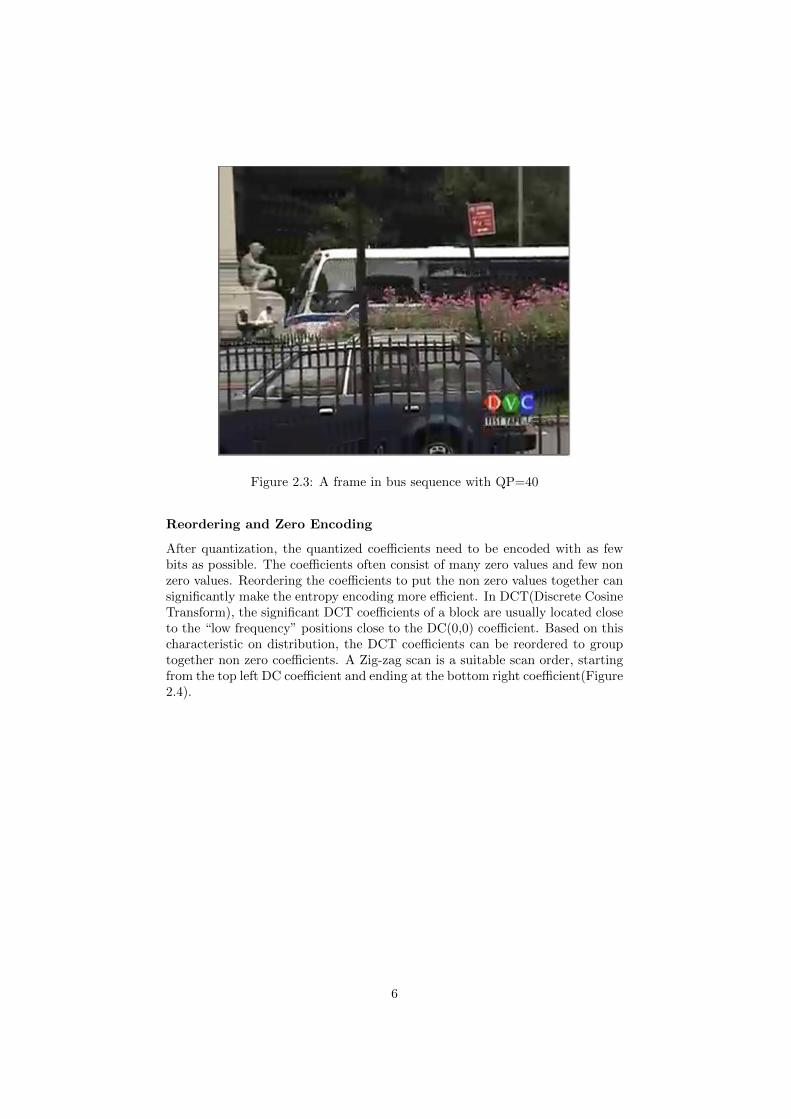
Figure 2.3: A frame in bus sequence with QP=40
Reordering and Zero Encoding
After quantization, the quantized coefficients need to be encoded with as fewbits as possible. The coefficients often consist of many zero values and few nonzero values. Reordering the coefficients to put the non zero values together cansignificantly make the entropy encoding more efficient. In DCT(Discrete CosineTransform), the significant DCT coefficients of a block are usually located closeto the “low frequency” positions close to the DC(0,0) coefficient. Based on thischaracteristic on distribution, the DCT coefficients can be reordered to grouptogether non zero coefficients. A Zig-zag scan is a suitable scan order, startingfrom the top left DC coefficient and ending at the bottom right coefficient(Figure2.4).
6
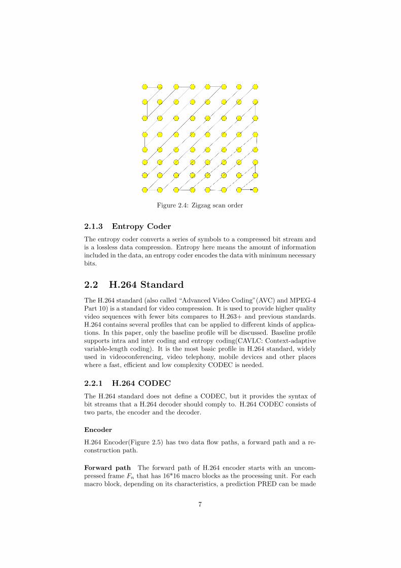
Figure 2.4: Zigzag scan order
2.1.3 Entropy Coder
The entropy coder converts a series of symbols to a compressed bit stream andis a lossless data compression. Entropy here means the amount of informationincluded in the data, an entropy coder encodes the data with minimum necessarybits.
2.2 H.264 Standard
The H.264 standard (also called “Advanced Video Coding”(AVC) and MPEG-4Part 10) is a standard for video compression. It is used to provide higher qualityvideo sequences with fewer bits compares to H.263+ and previous standards.H.264 contains several profiles that can be applied to different kinds of applica-tions. In this paper, only the baseline profile will be discussed. Baseline profilesupports intra and inter coding and entropy coding(CAVLC: Context-adaptivevariable-length coding). It is the most basic profile in H.264 standard, widelyused in videoconferencing, video telephony, mobile devices and other placeswhere a fast, efficient and low complexity CODEC is needed.
2.2.1 H.264 CODEC
The H.264 standard does not define a CODEC, but it provides the syntax ofbit streams that a H.264 decoder should comply to. H.264 CODEC consists oftwo parts, the encoder and the decoder.
Encoder
H.264 Encoder(Figure 2.5) has two data flow paths, a forward path and a re-construction path.
Forward path The forward path of H.264 encoder starts with an uncom-pressed frame Fn that has 16*16 macro blocks as the processing unit. For eachmacro block, depending on its characteristics, a prediction PRED can be made
7
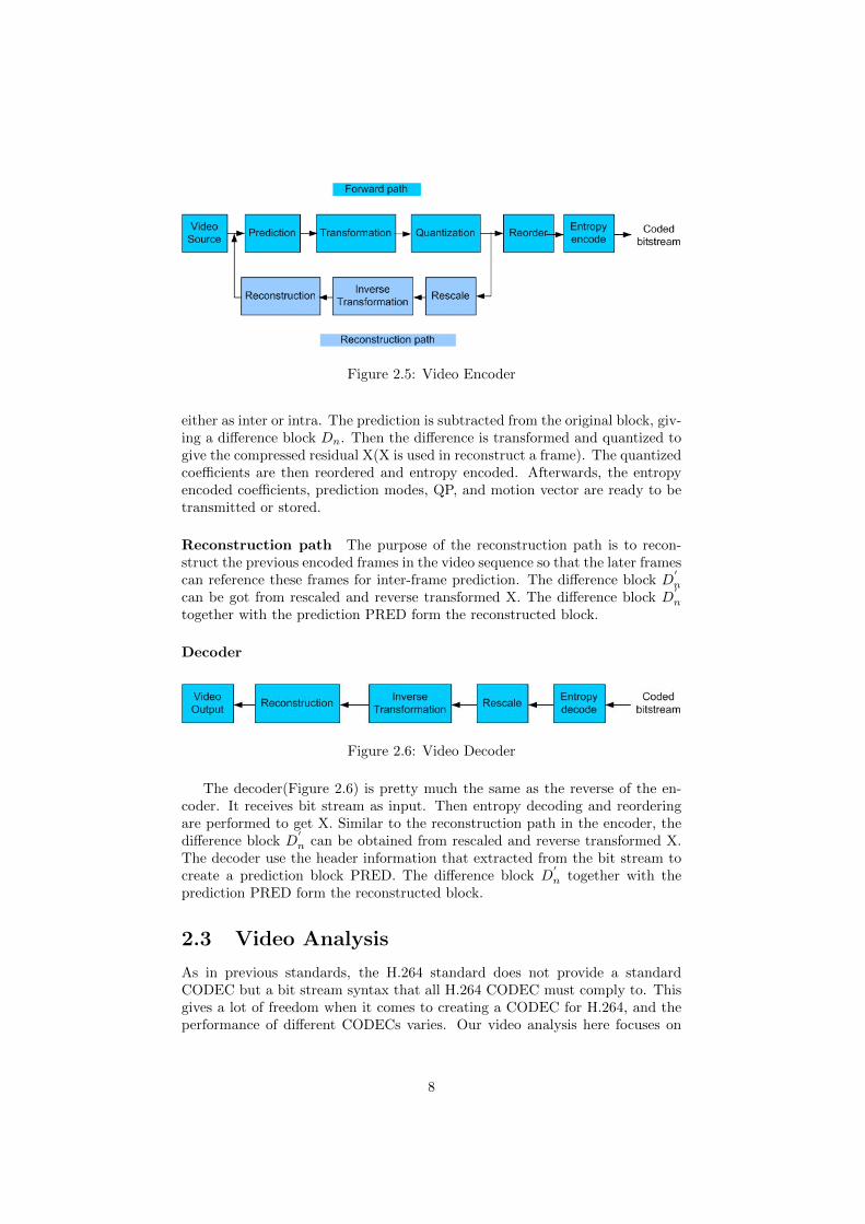
Figure 2.5: Video Encoder
either as inter or intra. The prediction is subtracted from the original block, giv-ing a difference block Dn. Then the difference is transformed and quantized togive the compressed residual X(X is used in reconstruct a frame). The quantizedcoefficients are then reordered and entropy encoded. Afterwards, the entropyencoded coefficients, prediction modes, QP, and motion vector are ready to betransmitted or stored.
Reconstruction path The purpose of the reconstruction path is to recon-struct the previous encoded frames in the video sequence so that the later framescan reference these frames for inter-frame prediction. The difference block D
′
n
can be got from rescaled and reverse transformed X. The difference block D′
n
together with the prediction PRED form the reconstructed block.
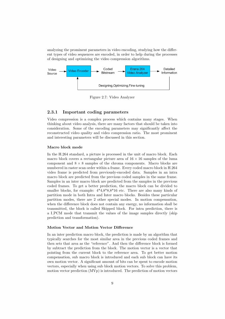
Decoder
Figure 2.6: Video Decoder
The decoder(Figure 2.6) is pretty much the same as the reverse of the en-coder. It receives bit stream as input. Then entropy decoding and reorderingare performed to get X. Similar to the reconstruction path in the encoder, thedifference block D
′
n can be obtained from rescaled and reverse transformed X.The decoder use the header information that extracted from the bit stream tocreate a prediction block PRED. The difference block D
′
n together with theprediction PRED form the reconstructed block.
2.3 Video Analysis
As in previous standards, the H.264 standard does not provide a standardCODEC but a bit stream syntax that all H.264 CODEC must comply to. Thisgives a lot of freedom when it comes to creating a CODEC for H.264, and theperformance of different CODECs varies. Our video analysis here focuses on
8
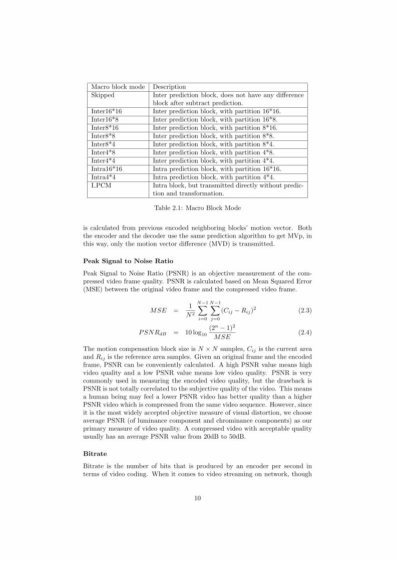
analyzing the prominent parameters in video encoding, studying how the differ-ent types of video sequences are encoded, in order to help during the processesof designing and optimizing the video compression algorithms.
Figure 2.7: Video Analyzer
2.3.1 Important coding parameters
Video compression is a complex process which contains many stages. Whenthinking about video analysis, there are many factors that should be taken intoconsideration. Some of the encoding parameters may significantly affect thereconstructed video quality and video compression ratio. The most prominentand interesting parameters will be discussed in this section.
Macro block mode
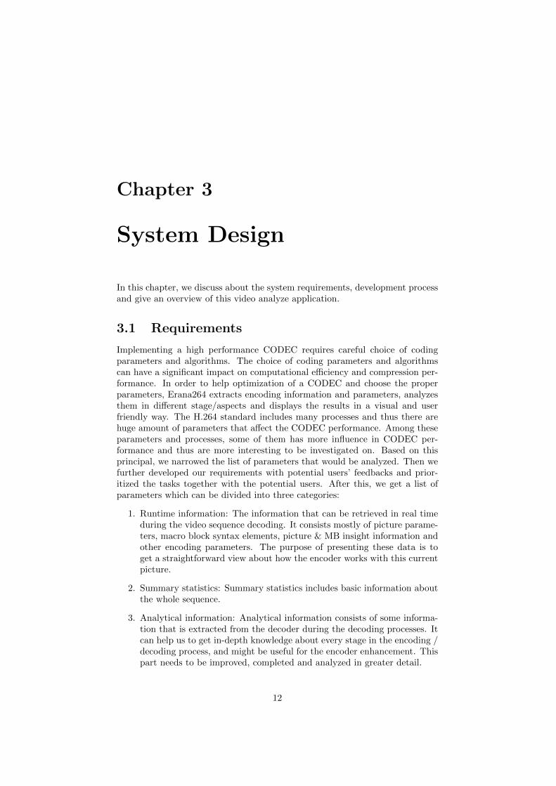
In the H.264 standard, a picture is processed in the unit of macro block. Eachmacro block covers a rectangular picture area of 16 × 16 samples of the lumacomponent and 8 × 8 samples of the chroma components. Macro blocks arenumbered in raster scan order within a frame. Every coded macro block in H.264video frame is predicted from previously-encoded data. Samples in an intramacro block are predicted from the previous coded samples in the same frame.Samples in an inter macro block are predicted from the samples in the previouscoded frames. To get a better prediction, the macro block can be divided tosmaller blocks, for example: 4*4,8*8,8*16 etc. There are also many kinds ofpartition mode in both Intra and Inter macro blocks. Besides these particularpartition modes, there are 2 other special modes. In motion compensation,when the difference block does not contain any energy, no information shall betransmitted, the block is called Skipped block. For intra prediction, there isa I PCM mode that transmit the values of the image samples directly (skipprediction and transformation).
Motion Vector and Motion Vector Difference
In an inter prediction macro block, the prediction is made by an algorithm thattypically searches for the most similar area in the previous coded frames andthen sets that area as the “reference”. And then the difference block is formedby subtract the prediction from the block. The motion vector is a vector thatpointing from the current block to the reference area. To get better motioncompensation, sub macro block is introduced and each sub block can have itsown motion vector. A significant amount of bits can be spent to encode motionvectors, especially when using sub block motion vectors. To solve this problem,motion vector prediction (MVp) is introduced. The prediction of motion vectors
9
Macro block mode DescriptionSkipped Inter prediction block, does not have any difference
block after subtract prediction.Inter16*16 Inter prediction block, with partition 16*16.Inter16*8 Inter prediction block, with partition 16*8.Inter8*16 Inter prediction block, with partition 8*16.Inter8*8 Inter prediction block, with partition 8*8.Inter8*4 Inter prediction block, with partition 8*4.Inter4*8 Inter prediction block, with partition 4*8.Inter4*4 Inter prediction block, with partition 4*4.Intra16*16 Intra prediction block, with partition 16*16.Intra4*4 Intra prediction block, with partition 4*4.I PCM Intra block, but transmitted directly without predic-
tion and transformation.
Table 2.1: Macro Block Mode
is calculated from previous encoded neighboring blocks’ motion vector. Boththe encoder and the decoder use the same prediction algorithm to get MVp, inthis way, only the motion vector difference (MVD) is transmitted.
Peak Signal to Noise Ratio
Peak Signal to Noise Ratio (PSNR) is an objective measurement of the com-pressed video frame quality. PSNR is calculated based on Mean Squared Error(MSE) between the original video frame and the compressed video frame.
MSE =1
N2
N−1∑i=0
N−1∑j=0
(Cij −Rij)2 (2.3)
PSNRdB = 10 log10
(2n − 1)2
MSE(2.4)
The motion compensation block size is N ×N samples, Cij is the current areaand Rij is the reference area samples. Given an original frame and the encodedframe, PSNR can be conveniently calculated. A high PSNR value means highvideo quality and a low PSNR value means low video quality. PSNR is verycommonly used in measuring the encoded video quality, but the drawback isPSNR is not totally correlated to the subjective quality of the video. This meansa human being may feel a lower PSNR video has better quality than a higherPSNR video which is compressed from the same video sequence. However, sinceit is the most widely accepted objective measure of visual distortion, we chooseaverage PSNR (of luminance component and chrominance components) as ourprimary measure of video quality. A compressed video with acceptable qualityusually has an average PSNR value from 20dB to 50dB.
Bitrate
Bitrate is the number of bits that is produced by an encoder per second interms of video coding. When it comes to video streaming on network, though
10

the network bit rates is increasing rapidly, it is still necessary to compress thevideo to a reasonable bit rates and quality. Lower bit rate and higher quality(PSNR) are the goal of video compression development.
11
Chapter 3
System Design
In this chapter, we discuss about the system requirements, development processand give an overview of this video analyze application.
3.1 Requirements
Implementing a high performance CODEC requires careful choice of codingparameters and algorithms. The choice of coding parameters and algorithmscan have a significant impact on computational efficiency and compression per-formance. In order to help optimization of a CODEC and choose the properparameters, Erana264 extracts encoding information and parameters, analyzesthem in different stage/aspects and displays the results in a visual and userfriendly way. The H.264 standard includes many processes and thus there arehuge amount of parameters that affect the CODEC performance. Among theseparameters and processes, some of them has more influence in CODEC per-formance and thus are more interesting to be investigated on. Based on thisprincipal, we narrowed the list of parameters that would be analyzed. Then wefurther developed our requirements with potential users’ feedbacks and prior-itized the tasks together with the potential users. After this, we get a list ofparameters which can be divided into three categories:
1. Runtime information: The information that can be retrieved in real timeduring the video sequence decoding. It consists mostly of picture parame-ters, macro block syntax elements, picture & MB insight information andother encoding parameters. The purpose of presenting these data is toget a straightforward view about how the encoder works with this currentpicture.
2. Summary statistics: Summary statistics includes basic information aboutthe whole sequence.
3. Analytical information: Analytical information consists of some informa-tion that is extracted from the decoder during the decoding processes. Itcan help us to get in-depth knowledge about every stage in the encoding /decoding process, and might be useful for the encoder enhancement. Thispart needs to be improved, completed and analyzed in greater detail.
12
3.2 Development environment and programminglanguages
C/C++ is used in the parts that are within H.264 Decoder and interfacingwith H.264 Decoder. The upper layers and the user interface are written inC#. This application is developed under Windows Vista Enterprise Version.Following tools are used during development:
• Microsoft Visual Studio 2008 (Compiler)
• TortoiseSVN 1.6.5 (Version Control)
3.3 Development Process
The development process of Erana264 consists three stages, at the first we col-lected user requirements and prioritized the tasks; then we implemented thisanalysis application; the last part was to run simulation and fine tuning.
3.3.1 Collect user requirements
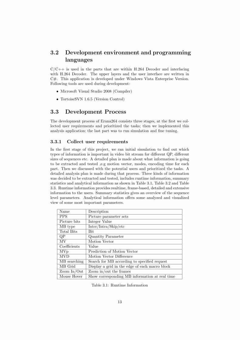
In the first stage of this project, we ran initial simulation to find out whichtypes of information is important in video bit stream for different QP, differentsizes of sequences etc. A detailed plan is made about what information is goingto be extracted and tested ,e.g motion vector, modes, encoding time for eachpart. Then we discussed with the potential users and prioritized the tasks. Adetailed analysis plan is made during that process. Three kinds of informationwas decided to be extracted and tested, includes runtime information, summarystatistics and analytical information as shown in Table 3.1, Table 3.2 and Table3.3. Runtime information provides realtime, frame-based, detailed and extensiveinformation to the users. Summary statistics gives an overview of the sequencelevel parameters. Analytical information offers some analyzed and visualizedview of some most important parameters.
Name DescriptionPPS Picture parameter setsPicture bits Integer ValueMB type Inter/Intra/Skip/etcTotal Bits BitQP Quantity ParameterMV Motion VectorCoefficients ValueMVp Prediction of Motion VectorMVD Motion Vector DifferenceMB searching Search for MB according to specified requestMB Grid Display a grid in the edge of each macro blockZoom In/Out Zoom in/out the framesMouse Hover Show corresponding MB information at real time
Table 3.1: Runtime Information
13
Name DescriptionProfile BaselineVideo Format 4:2:0 / 4:2:2Level ValueResolution Width and height in pixelsPictures Decoded The total number of pictures that have been decodedQP Min / Max / Avg / Bits spent on QPMode/Partition Summary Info Counting, PercentageTime Cost Time cost for decoding the video sequenceBit rate Kbps
Table 3.2: Summary Statistics
Name DescriptionPredicted Picture Display the predicted pictureResidual Picture Display the residual pictureDistribution of MV length ChartPSNR ChartLuma/Chroma Display Luma/Chroma component separately
Table 3.3: Analytical Information
3.3.2 Implementation
The second step was to implement analyzer code to collect all the data that isplaned to be investigated and present it in a user friendly and visual format.Based on the parameters’ property, they are displayed as pictures, overlay ontop of the frame, lists or charts. Pictures are used to visualize the residual,predicted and reconstructed frames. Overlay display provides a more straight-forward view to the users, it suits the parameters that differs for each macroblockin the same frame very well. Lists gives clear and general information for pa-rameters in picture level, sequence level and some less important parameters inmacroblock level. Chart is the best choice when we want to do comparison forsome parameters between different frames and see how this parameter variesduring the whole sequence.
3.3.3 Simulation utilizing and Fine-tuning
The last step is to run simulation of the developed analysis tool on differentsequences, using it to find out interesting information that could be the sourcefor help generating new ideas of performance improvement. Also some fine-tuning work is done based on these experiments. We also talked to the potentialusers and got valuable feedbacks and integrated some new features at this stage.
3.4 System Structure
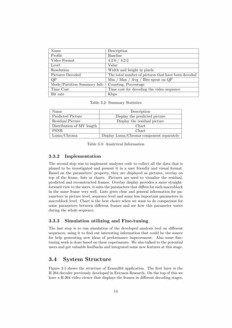
Figure 3.1 shows the structure of Erana264 application. The first layer is theH.264 decoder previously developed in Ericsson Research. On the top of this wehave a H.264 video viewer that displays the frames in different decoding stages,
14
the overlay display of some macroblock level and picture level parameters on thetop of the picture and an overview of the whole video sequence. Beside these,we retrieve some macroblock level parameters and sequence level parameters,list them in different tables. We also use some charts to visualize the PSNRvalues against frames, picture bits distribution and motion vector distributionetc.
Figure 3.1: Erana264 System Structure
15
Chapter 4
Erana264 Functionality
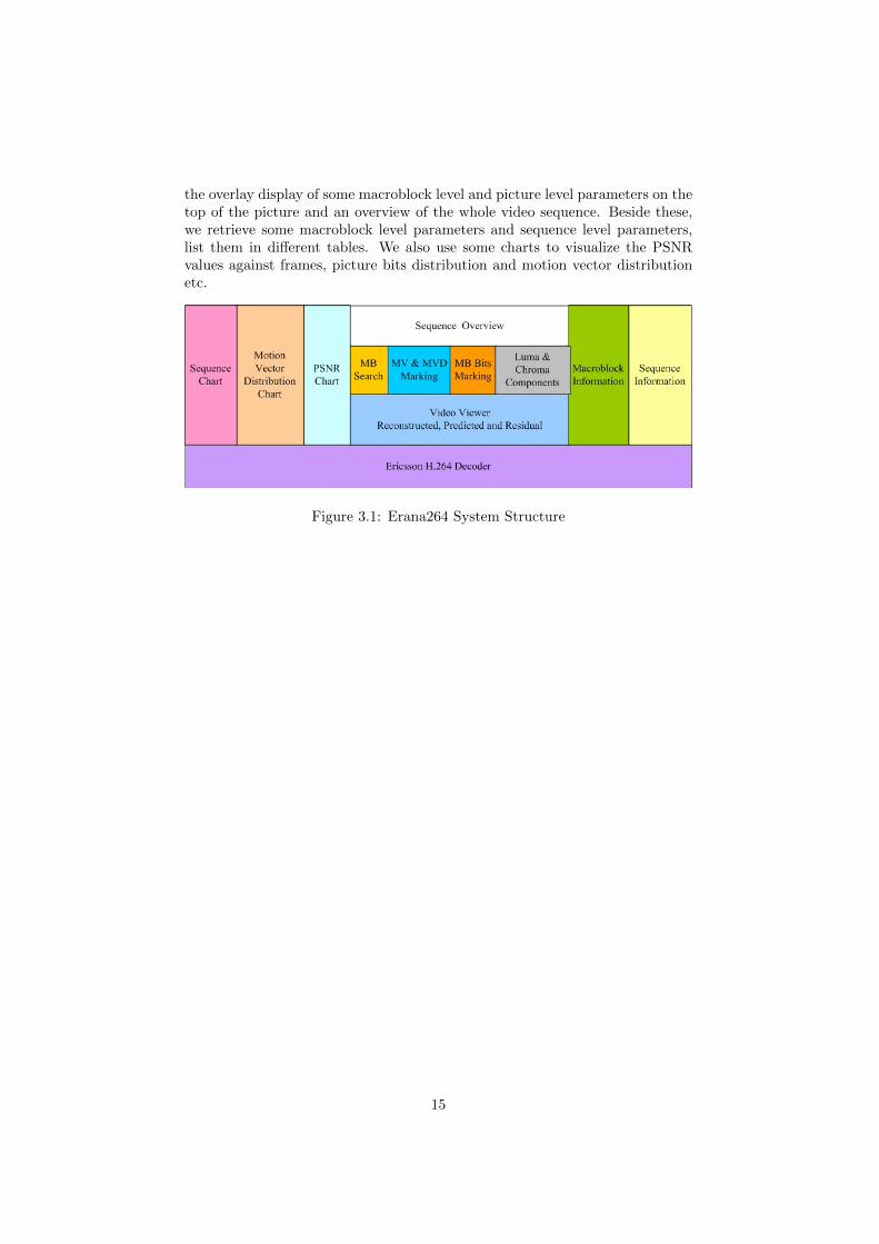
Erana264(Figure 4.1) is an extensive H.264 video bitstream analyzer which ex-tracts and analysis encoding parameters in different video encoding stages. Wediscuss about the main functions of Erana264 in this chapter. As a H.264 videoreal time analyzer, instead of decoding the whole sequence as soon as openingthe sequence, Erana264 decodes in a frame by frame fashion, one frame is de-coded right before it is displayed. This helps to reduce the waiting time fordecoding a long sequence or a high resolution sequence and also accelerate re-sponse time. However, users can specify a buffer size for storing the previousdecoded frames.
Figure 4.1: Erana264 Screenshot
16
4.1 Erana264 Overview
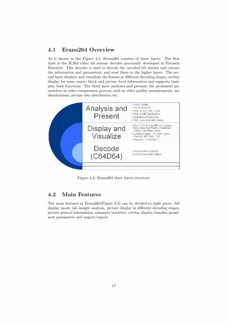
As is shown in the Figure 4.2, Erana264 consists of three layers. The firstlayer is the H.264 video bit stream decoder previously developed in EricssonResearch. This decoder is used to decode the encoded bit stream and extractthe information and parameters, and send them to the higher layers. The sec-ond layer displays and visualizes the frames at different decoding stages, overlaydisplay for some macro block and picture level information and supports basicplay back functions. The third layer analyzes and presents the prominent pa-rameters in video compression process, such as video quality measurements, mvdistributions, picture bits distribution etc.
Figure 4.2: Erana264 three layers structure
4.2 Main Features
The main features in Erana264(Figure 4.3) can be divided to eight parts: fulldisplay mode, mb insight analysis, picture display in different decoding stages,picture general information, summary statistics, overlay display,visualize promi-nent parameters and import/export.
17
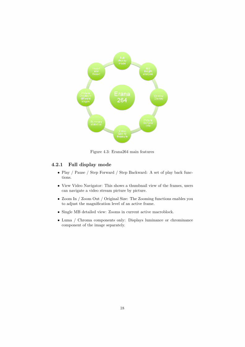
Figure 4.3: Erana264 main features
4.2.1 Full display mode
• Play / Pause / Step Forward / Step Backward: A set of play back func-tions.
• View Video Navigator: This shows a thumbnail view of the frames, userscan navigate a video stream picture by picture.
• Zoom In / Zoom Out / Original Size: The Zooming functions enables youto adjust the magnification level of an active frame.
• Single MB detailed view: Zooms in current active macroblock.
• Luma / Chroma components only: Displays luminance or chrominancecomponent of the image separately.
18
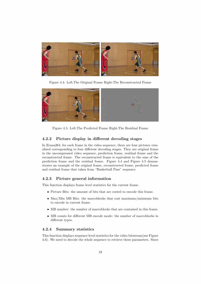
Figure 4.4: Left:The Original Frame Right:The Reconstructed Frame
Figure 4.5: Left:The Predicted Frame Right:The Residual Frame
4.2.2 Picture display in different decoding stages
In Erana264, for each frame in the video sequence, there are four pictures visu-alized corresponding to four different decoding stages. They are original framein the uncompressed video sequence, prediction frame, residual frame and thereconstructed frame. The reconstructed frame is equivalent to the sum of theprediction frame and the residual frame. Figure 4.4 and Figure 4.5 demon-strates an example of the original frame, reconstructed frame, predicted frameand residual frame that taken from “Basketball Pass” sequence.
4.2.3 Picture general information
This function displays frame level statistics for the current frame.
• Picture Bits: the amount of bits that are costed to encode this frame.
• Max/Min MB Bits: the macroblocks that cost maximum/minimum bitsto encode in current frame.
• MB number: the number of macroblocks that are contained in this frame.
• MB counts for different MB encode mode: the number of macroblocks indifferent types.
4.2.4 Summary statistics
This function displays sequence level statistics for the video bitstream(see Figure4.6). We need to decode the whole sequence to retrieve these parameters. Since
19
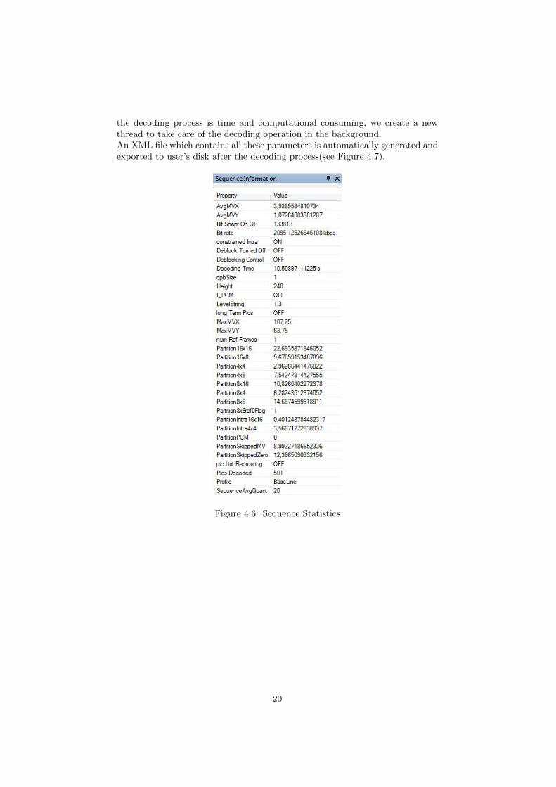
the decoding process is time and computational consuming, we create a newthread to take care of the decoding operation in the background.An XML file which contains all these parameters is automatically generated andexported to user’s disk after the decoding process(see Figure 4.7).
Figure 4.6: Sequence Statistics
20
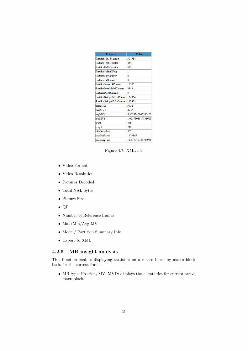
Figure 4.7: XML file
• Video Format
• Video Resolution
• Pictures Decoded
• Total NAL bytes
• Picture Size
• QP
• Number of Reference frames
• Max/Min/Avg MV
• Mode / Partition Summary Info
• Export to XML
4.2.5 MB insight analysis
This function enables displaying statistics on a macro block by macro blockbasis for the current frame.
• MB type, Position, MV, MVD: displays these statistics for current activemacroblock.
21
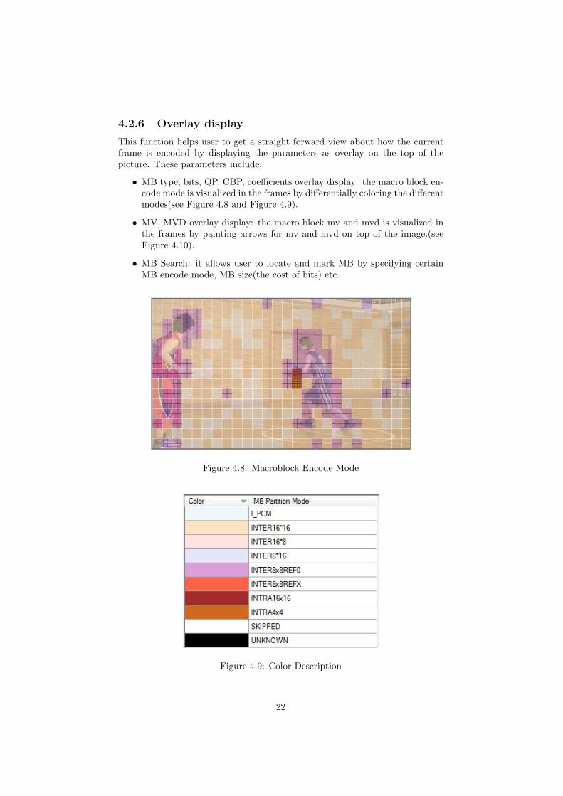
4.2.6 Overlay display
This function helps user to get a straight forward view about how the currentframe is encoded by displaying the parameters as overlay on the top of thepicture. These parameters include:
• MB type, bits, QP, CBP, coefficients overlay display: the macro block en-code mode is visualized in the frames by differentially coloring the differentmodes(see Figure 4.8 and Figure 4.9).
• MV, MVD overlay display: the macro block mv and mvd is visualized inthe frames by painting arrows for mv and mvd on top of the image.(seeFigure 4.10).
• MB Search: it allows user to locate and mark MB by specifying certainMB encode mode, MB size(the cost of bits) etc.
Figure 4.8: Macroblock Encode Mode
Figure 4.9: Color Description
22
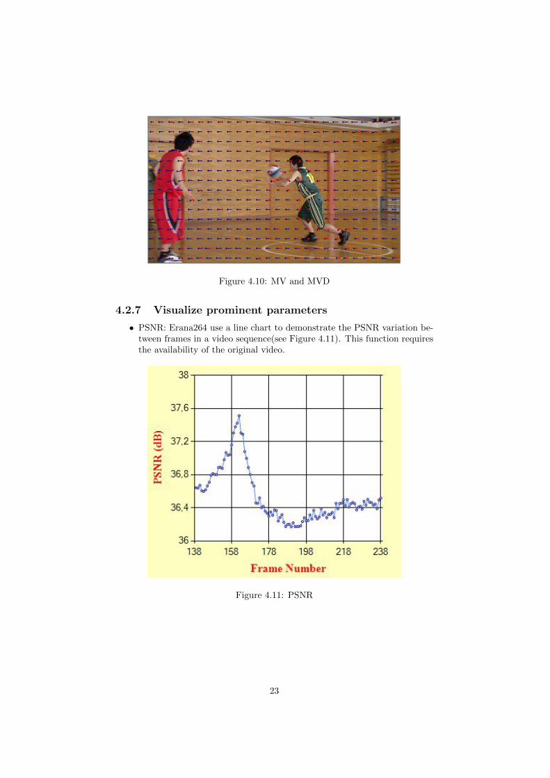
Figure 4.10: MV and MVD
4.2.7 Visualize prominent parameters
• PSNR: Erana264 use a line chart to demonstrate the PSNR variation be-tween frames in a video sequence(see Figure 4.11). This function requiresthe availability of the original video.
Figure 4.11: PSNR
23
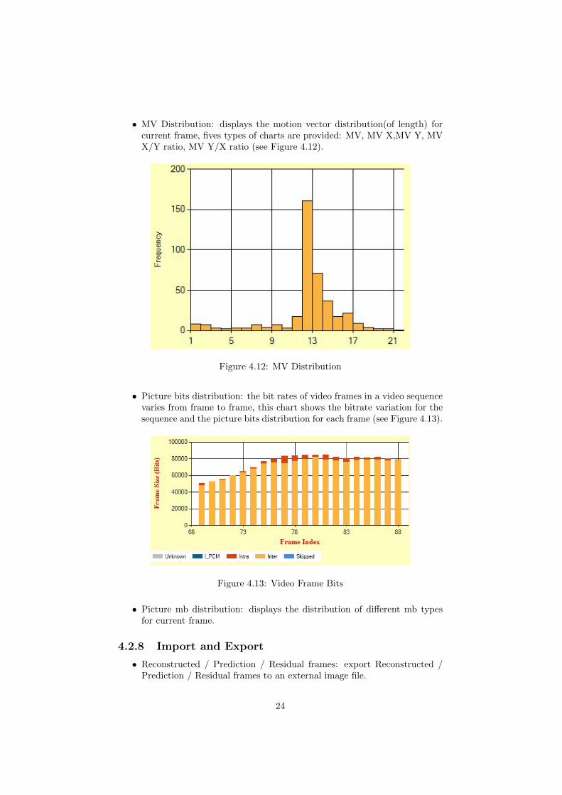
• MV Distribution: displays the motion vector distribution(of length) forcurrent frame, fives types of charts are provided: MV, MV X,MV Y, MVX/Y ratio, MV Y/X ratio (see Figure 4.12).
Figure 4.12: MV Distribution
• Picture bits distribution: the bit rates of video frames in a video sequencevaries from frame to frame, this chart shows the bitrate variation for thesequence and the picture bits distribution for each frame (see Figure 4.13).
Figure 4.13: Video Frame Bits
• Picture mb distribution: displays the distribution of different mb typesfor current frame.
4.2.8 Import and Export
• Reconstructed / Prediction / Residual frames: export Reconstructed /Prediction / Residual frames to an external image file.
24

• Charts: Export / Import the charts to / from an external XML file.
25
Chapter 5
Experiments
We conducted two different experiments in this chapter in order to demonstrateand validate this application. Each of these two experiments is targeting a par-ticular application area. In the first experiment we compared different encodingparameters with the same video sequence. In the second experiment we madea comparison between different video sequences which are encoded by the sameencoding parameters.
5.1 Comparison between different encoding pa-rameter with same video sequence
Erana264 enables user to do comparison between different encoding parametersand algorithms. It provides a straight forward view to see the encoding perfor-mance of different configurations. We choose “Basketball Pass” video sequencewith resolution 416×240 pixels, frame rate 50fps with the length of 500 frames.This sequence has fast camera and content motion with random movement.We encode this sequence with four different configurations(an internal H.264encoder previously developed in Ericsson Research was used to encode thesesequences). These configurations are named as “speed 1”,“speed 2”,“speed 3”and “speed 4”. These four configurations use different RDO(Rate DistortionOptimize) algorithms and motion vector searching algorithms.
• Speed 4: Only supports full pixel motion vector. Speed 4 does not supportsub macroblock. For Intra prediction, only Intra16×16 with DC predictionis supported.
• Speed 3: Comparing to speed 4, the support to point wise search for subpixel motion vectors is added.
• Speed 2: Comparing to speed 3, it calculates SAD after transformation.Computes rate distortion values for each inter candidate. Tries to find thebest intra mode, supports intra4 × 4 mode.
• Speed 1: In addition to speed 2, using RDO when searching for motionvectors, computes SAD for all block partitions. Chooses the best intramode based on rate-distortion.
26
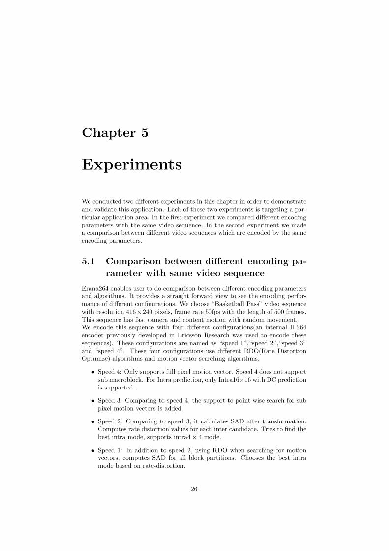
While we keep other parameters as the same(QP,profile etc.) The encodingtime for these different configurations are as following: Speed 1: Encoding Time= 329.6168s; Speed 2: Encoding Time = 10.7884s; Speed 3: Encoding Time =4.3979s; Speed 4: Encoding Time = 2.9490s.
5.1.1 Sequence Statistics
Figure 5.1 shows the summary information of these different settings. The speed1 provides approximately 35% bit-rate savings over speed 4, closely followedby speed 2. Speed 3 and speed 4 do not support sub macroblock partitions.Speed 1 has larger motion vector searching range comparing to the other threeconfigurations.
Figure 5.1: Sequence Statistics Comparison
27
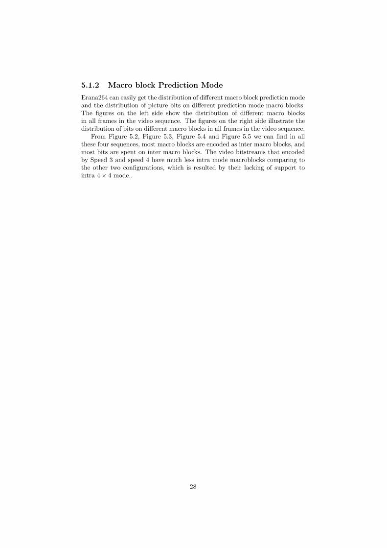
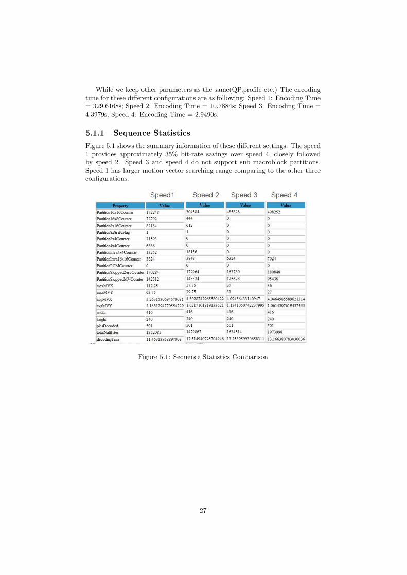
5.1.2 Macro block Prediction Mode
Erana264 can easily get the distribution of different macro block prediction modeand the distribution of picture bits on different prediction mode macro blocks.The figures on the left side show the distribution of different macro blocksin all frames in the video sequence. The figures on the right side illustrate thedistribution of bits on different macro blocks in all frames in the video sequence.
From Figure 5.2, Figure 5.3, Figure 5.4 and Figure 5.5 we can find in allthese four sequences, most macro blocks are encoded as inter macro blocks, andmost bits are spent on inter macro blocks. The video bitstreams that encodedby Speed 3 and speed 4 have much less intra mode macroblocks comparing tothe other two configurations, which is resulted by their lacking of support tointra 4 × 4 mode..
28
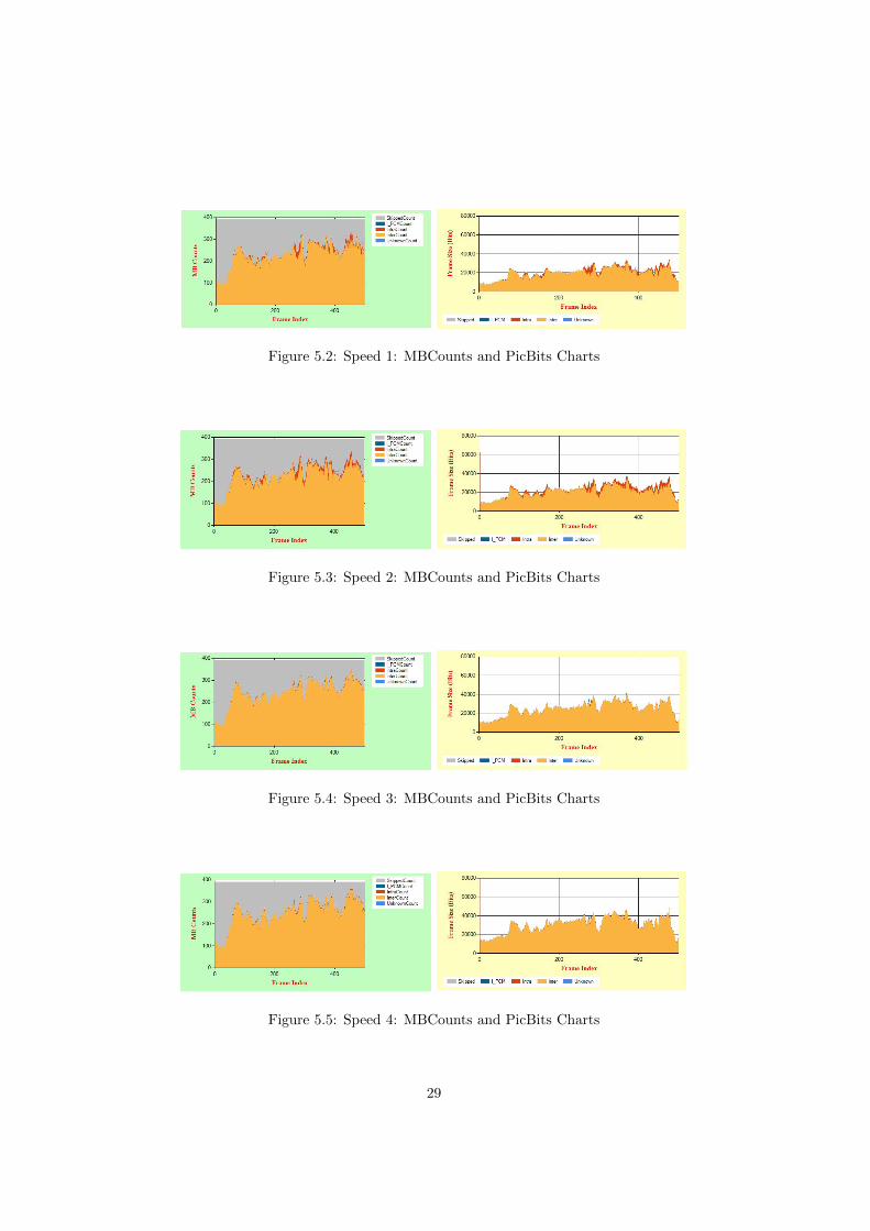
Figure 5.2: Speed 1: MBCounts and PicBits Charts
Figure 5.3: Speed 2: MBCounts and PicBits Charts
Figure 5.4: Speed 3: MBCounts and PicBits Charts
Figure 5.5: Speed 4: MBCounts and PicBits Charts
29
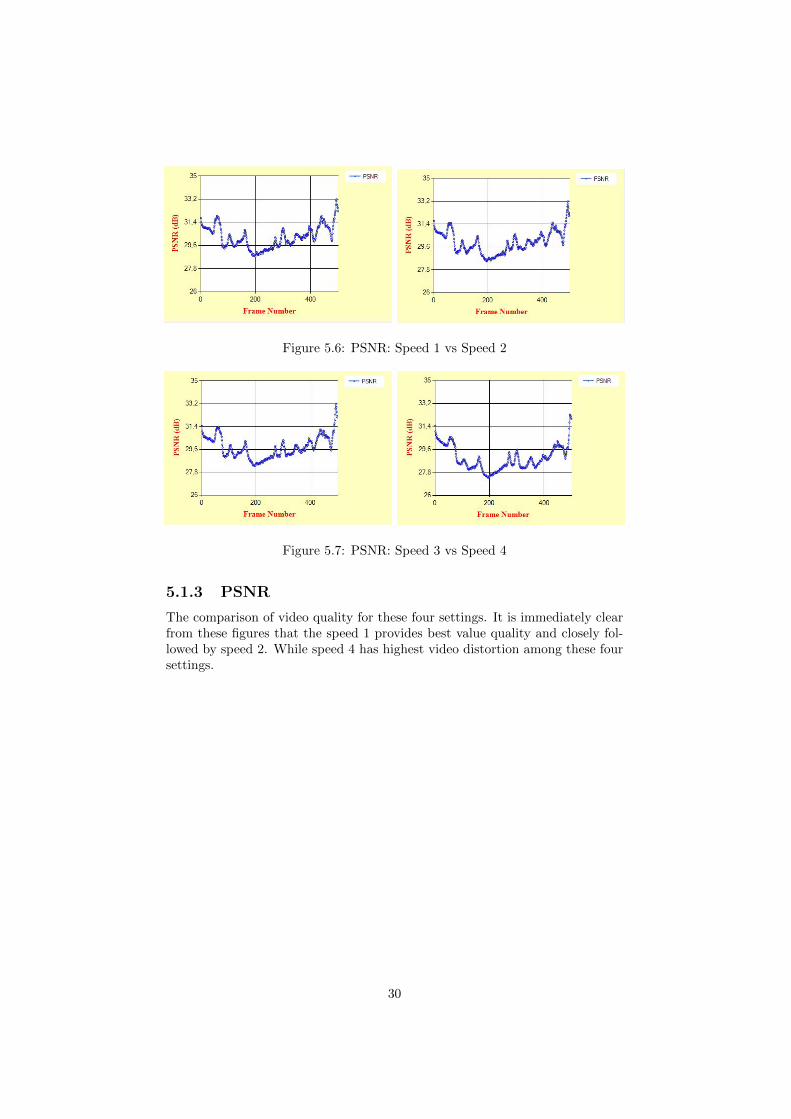
Figure 5.6: PSNR: Speed 1 vs Speed 2
Figure 5.7: PSNR: Speed 3 vs Speed 4
5.1.3 PSNR
The comparison of video quality for these four settings. It is immediately clearfrom these figures that the speed 1 provides best value quality and closely fol-lowed by speed 2. While speed 4 has highest video distortion among these foursettings.
30
5.2 Comparison between different video sequencewith same encoding parameters
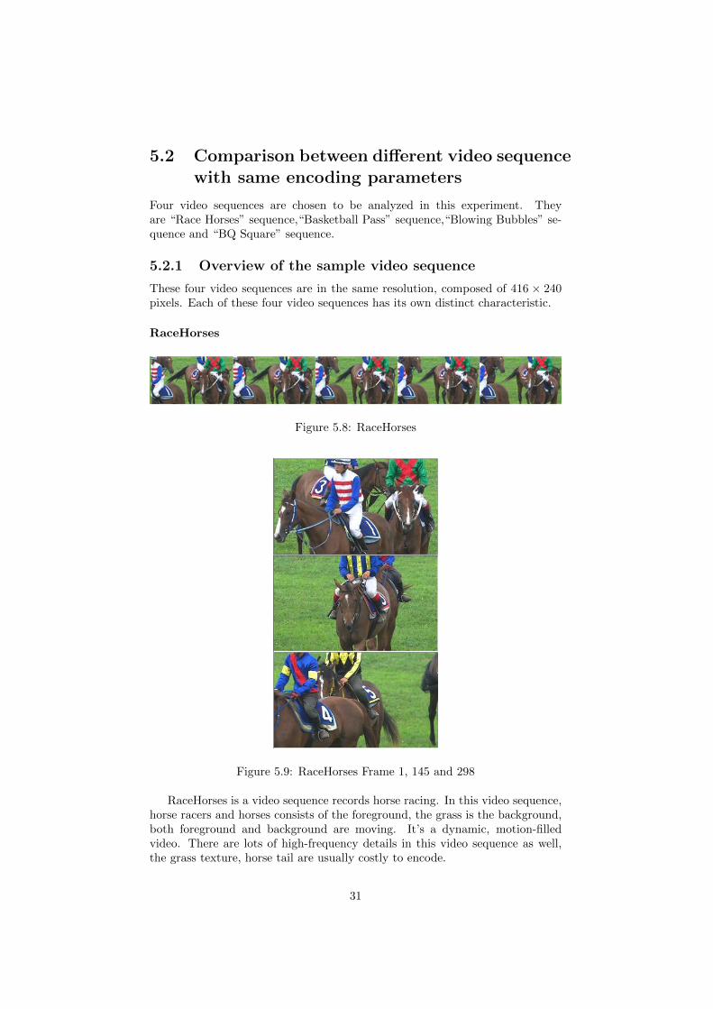
Four video sequences are chosen to be analyzed in this experiment. Theyare “Race Horses” sequence,“Basketball Pass” sequence,“Blowing Bubbles” se-quence and “BQ Square” sequence.
5.2.1 Overview of the sample video sequence
These four video sequences are in the same resolution, composed of 416 × 240pixels. Each of these four video sequences has its own distinct characteristic.
RaceHorses
Figure 5.8: RaceHorses
Figure 5.9: RaceHorses Frame 1, 145 and 298
RaceHorses is a video sequence records horse racing. In this video sequence,horse racers and horses consists of the foreground, the grass is the background,both foreground and background are moving. It’s a dynamic, motion-filledvideo. There are lots of high-frequency details in this video sequence as well,the grass texture, horse tail are usually costly to encode.
31
BasketballPass
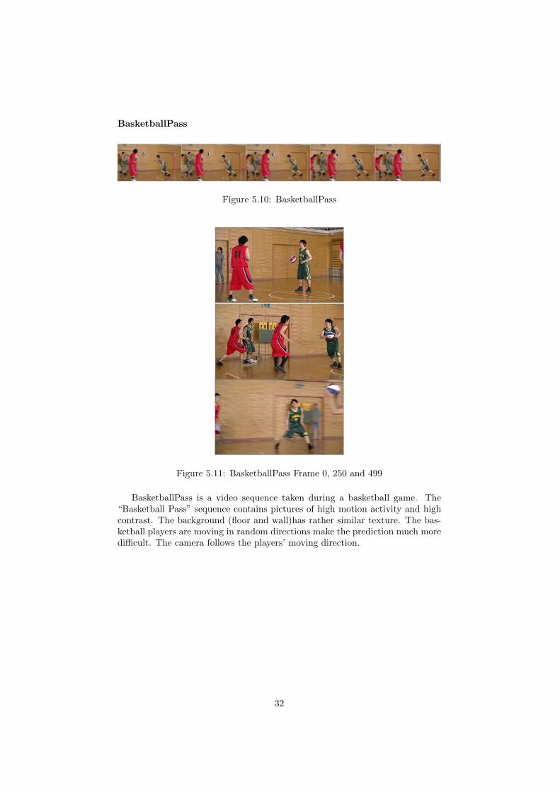
Figure 5.10: BasketballPass
Figure 5.11: BasketballPass Frame 0, 250 and 499
BasketballPass is a video sequence taken during a basketball game. The“Basketball Pass” sequence contains pictures of high motion activity and highcontrast. The background (floor and wall)has rather similar texture. The bas-ketball players are moving in random directions make the prediction much moredifficult. The camera follows the players’ moving direction.
32
BlowingBubbles
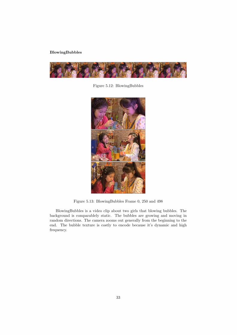
Figure 5.12: BlowingBubbles
Figure 5.13: BlowingBubbles Frame 0, 250 and 498
BlowingBubbles is a video clip about two girls that blowing bubbles. Thebackground is comparablely static. The bubbles are growing and moving inrandom directions. The camera zooms out generally from the beginning to theend. The bubble texture is costly to encode because it’s dynamic and highfrequency.
33

BQSquare
Figure 5.14: BQSquare
Figure 5.15: BQSquare Frame 0, 300 and 598
BQSquare is a video clip taken in a square. The background is low motion.Some people are moving in predicable directions with low speed. Generally thissequence has lower motion activities. The camera moves from the left to upright slowly.
34
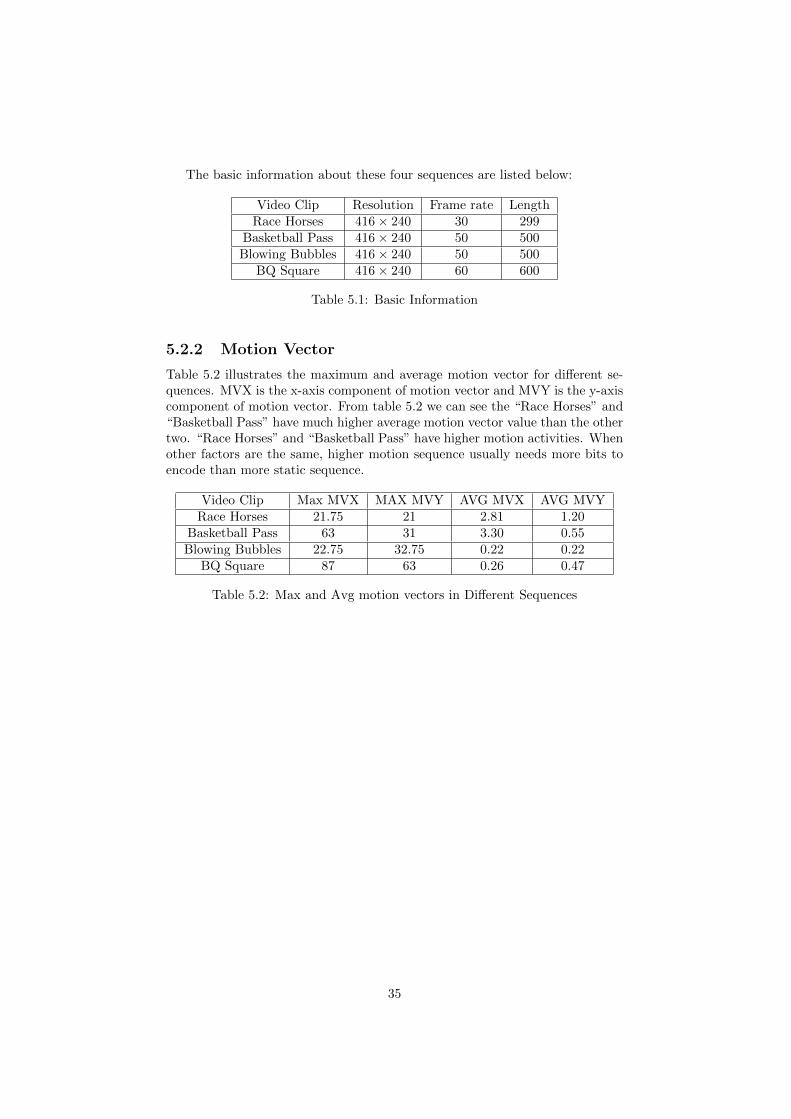
The basic information about these four sequences are listed below:
Video Clip Resolution Frame rate LengthRace Horses 416 × 240 30 299
Basketball Pass 416 × 240 50 500Blowing Bubbles 416 × 240 50 500
BQ Square 416 × 240 60 600
Table 5.1: Basic Information
5.2.2 Motion Vector
Table 5.2 illustrates the maximum and average motion vector for different se-quences. MVX is the x-axis component of motion vector and MVY is the y-axiscomponent of motion vector. From table 5.2 we can see the “Race Horses” and“Basketball Pass” have much higher average motion vector value than the othertwo. “Race Horses” and “Basketball Pass” have higher motion activities. Whenother factors are the same, higher motion sequence usually needs more bits toencode than more static sequence.
Video Clip Max MVX MAX MVY AVG MVX AVG MVYRace Horses 21.75 21 2.81 1.20
Basketball Pass 63 31 3.30 0.55Blowing Bubbles 22.75 32.75 0.22 0.22
BQ Square 87 63 0.26 0.47
Table 5.2: Max and Avg motion vectors in Different Sequences
35
5.2.3 PSNR
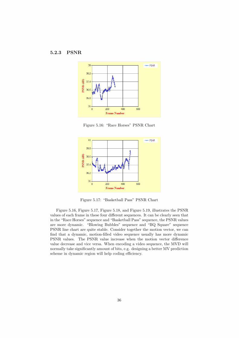
Figure 5.16: “Race Horses” PSNR Chart
Figure 5.17: “Basketball Pass” PSNR Chart
Figure 5.16, Figure 5.17, Figure 5.18, and Figure 5.19, illustrates the PSNRvalues of each frame in these four different sequences. It can be clearly seen thatin the “Race Horses” sequence and “Basketball Pass” sequence, the PSNR valuesare more dynamic. “Blowing Bubbles” sequence and “BQ Square” sequencePSNR line chart are quite stable. Consider together the motion vector, we canfind that a dynamic, motion-filled video sequence usually has more dynamicPSNR values. The PSNR value increase when the motion vector differencevalue decrease and vice versa. When encoding a video sequence, the MVD willnormally take significantly amount of bits, e.g. designing a better MV predictionscheme in dynamic region will help coding efficiency.
36
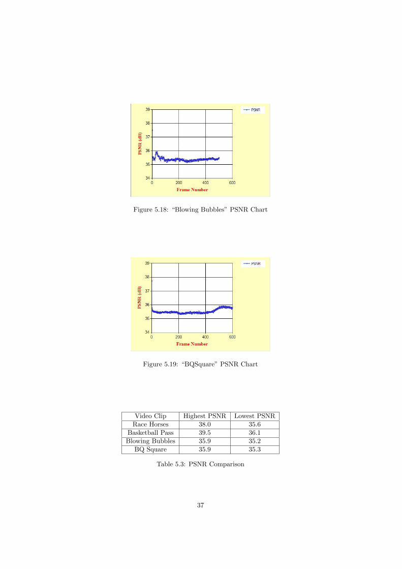
Figure 5.18: “Blowing Bubbles” PSNR Chart
Figure 5.19: “BQSquare” PSNR Chart
Video Clip Highest PSNR Lowest PSNRRace Horses 38.0 35.6
Basketball Pass 39.5 36.1Blowing Bubbles 35.9 35.2
BQ Square 35.9 35.3
Table 5.3: PSNR Comparison
37

5.2.4 Macro block Prediction Mode
Erana264 can easily get the distribution of different macro block mode and thedistribution of picture bits on different prediction macro block modes. The leftfigures show the distribution of different macro blocks in all frames in the videosequence. The right figures illustrate the distribution of bits on different macroblocks in all frames in the video sequence.
From Figure 5.20,Figure 5.21,Figure 5.22 and Figure 5.23 we can find in allthese four sequences, most macro blocks are encoded as inter macro blocks, andmost bits are spent on inter macro blocks.
38
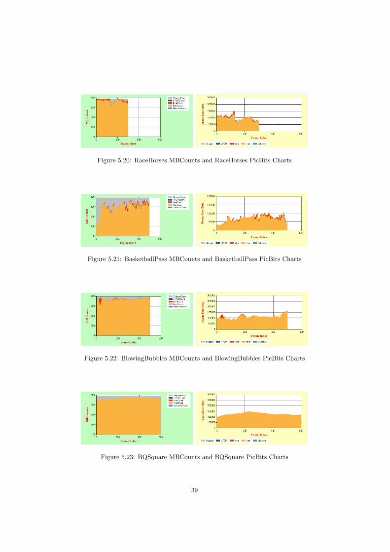
Figure 5.20: RaceHorses MBCounts and RaceHorses PicBits Charts
Figure 5.21: BasketballPass MBCounts and BasketballPass PicBits Charts
Figure 5.22: BlowingBubbles MBCounts and BlowingBubbles PicBits Charts
Figure 5.23: BQSquare MBCounts and BQSquare PicBits Charts
39
Video Clip Intra(%) Inter(%) Skipped(%)Race Horses 2.60 93.14 4.26
Basketball Pass 3.19 74.15 22.66Blowing Bubbles 1.35 93.42 5.23
BQ Square 0.32 93.05 6.63
Table 5.4: Macro block Prediction Mode
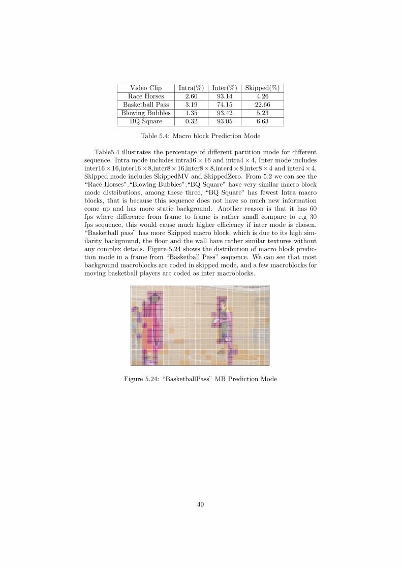
Table5.4 illustrates the percentage of different partition mode for differentsequence. Intra mode includes intra16× 16 and intra4 × 4, Inter mode includesinter16×16,inter16×8,inter8×16,inter8×8,inter4×8,inter8×4 and inter4×4,Skipped mode includes SkippedMV and SkippedZero. From 5.2 we can see the“Race Horses”,“Blowing Bubbles”,“BQ Square” have very similar macro blockmode distributions, among these three, “BQ Square” has fewest Intra macroblocks, that is because this sequence does not have so much new informationcome up and has more static background. Another reason is that it has 60fps where difference from frame to frame is rather small compare to e.g 30fps sequence, this would cause much higher efficiency if inter mode is chosen.“Basketball pass” has more Skipped macro block, which is due to its high sim-ilarity background, the floor and the wall have rather similar textures withoutany complex details. Figure 5.24 shows the distribution of macro block predic-tion mode in a frame from “Basketball Pass” sequence. We can see that mostbackground macroblocks are coded in skipped mode, and a few macroblocks formoving basketball players are coded as inter macroblocks.
Figure 5.24: “BasketballPass” MB Prediction Mode
40
Chapter 6
Conclusions and Furtherdevelopment
6.1 Conclusions
The video analysis application ERANA264 is developed in this project. We in-troduced the concepts of video compression, described the system design, wentthrough the main features and performed two experiments in this paper. Er-ana264 provides extensive functions to help with the development and optimiza-tion of video CODEC. A numerous video encoding parameters are extracted andanalyzed in this application, which can be divided into three categories:
1. Runtime information
2. Summary statistics
3. Analytical information
The main features in Erana264 can be divided to eight parts: full display mode,mb insight analysis, picture display in different decoding stages, picture generalinformation, summary statistics, overlay display, visualize prominent parame-ters and import/export.
6.2 Further development
The flat and extensive structure of this application opens up many possibilitiesfor future work. Currently, Erana264 only processes one sequence at a time,while sometimes users want to do some comparison between different encodingconfigurations, then the support for multiple sequence comparison would be anice functionality to be included.
Moreover, currently Erana264 only supports pure bitstream analysis, someextension could be made to support bitstream that contained in a container fileformat. For example, when the bitstream is encapsulated into RTP payloadformat, MPEG4 file format or 3GP file format etc.
It would also be interesting to generate XML format analytical report auto-matically, it saves users’ time and user can easily get access to these reports inthe disk afterwards.
41

PSNR is very commonly used in measuring the encoded video quality, butthe drawback is PSNR is not totally correlated to the subjective quality of thevideo. This means a human being may feel a lower PSNR video has betterquality than a higher PSNR video which is compressed from the same videosequence. I would also like to introduce some other video quality measures thatbetter correlated to the subjective quality measures.
42
Bibliography
[1] Richardson, Iain E.G., H.264 and MPEG-4 Video Compression, JohnWiley & Sons Ltd,, The Robert Gordon University Aberdeen,UK, 1st edi-tion, 2003
[2] Telecommunication Standardization Sector of ITU, H.264 Standard, Nov2007
[3] R. D. Dony, The Transform and Data Compression Handbook, CRC PressLLC,(2001), Chapter 1.
[4] Todd Will, Singular Value Decomposition,http://www.uwlax.edu/faculty/will/svd/svd/index.html, Retrieved 2010-05-26.
[5] Syed Ali Khayam, The Discrete Cosine Transform(DCT): Theory andApplication, Department of Electrical & Computer Engineering, MichiganState University, Mar 2003.
43
Related Documents