Analysis and technical functional modelling for the improvement of the vessel traffic management in the Adriatic Region 4.1.c_4.1.d_ Annex 1 Data mapping of the traffic monitoring systems in the Adriatic maritime traffic area and definition unique data mapping Version 1.1 Easyconnecting Project code 1 str./0002 This Project is co-founded by the European Union, Instrument for Pre-Accession Assistance

Welcome message from author
This document is posted to help you gain knowledge. Please leave a comment to let me know what you think about it! Share it to your friends and learn new things together.
Transcript

Analysis and technical functional modelling for the improvement of the vessel traffic management in the
Adriatic Region
4.1.c_4.1.d_ Annex 1Data mapping of the traffic monitoring systems in
the Adriatic maritime traffic area and definition unique data mapping
Version 1.1
Easyconnecting Project code 1 str./0002 This Project is co-founded by the European Union, Instrument for Pre-Accession Assistance
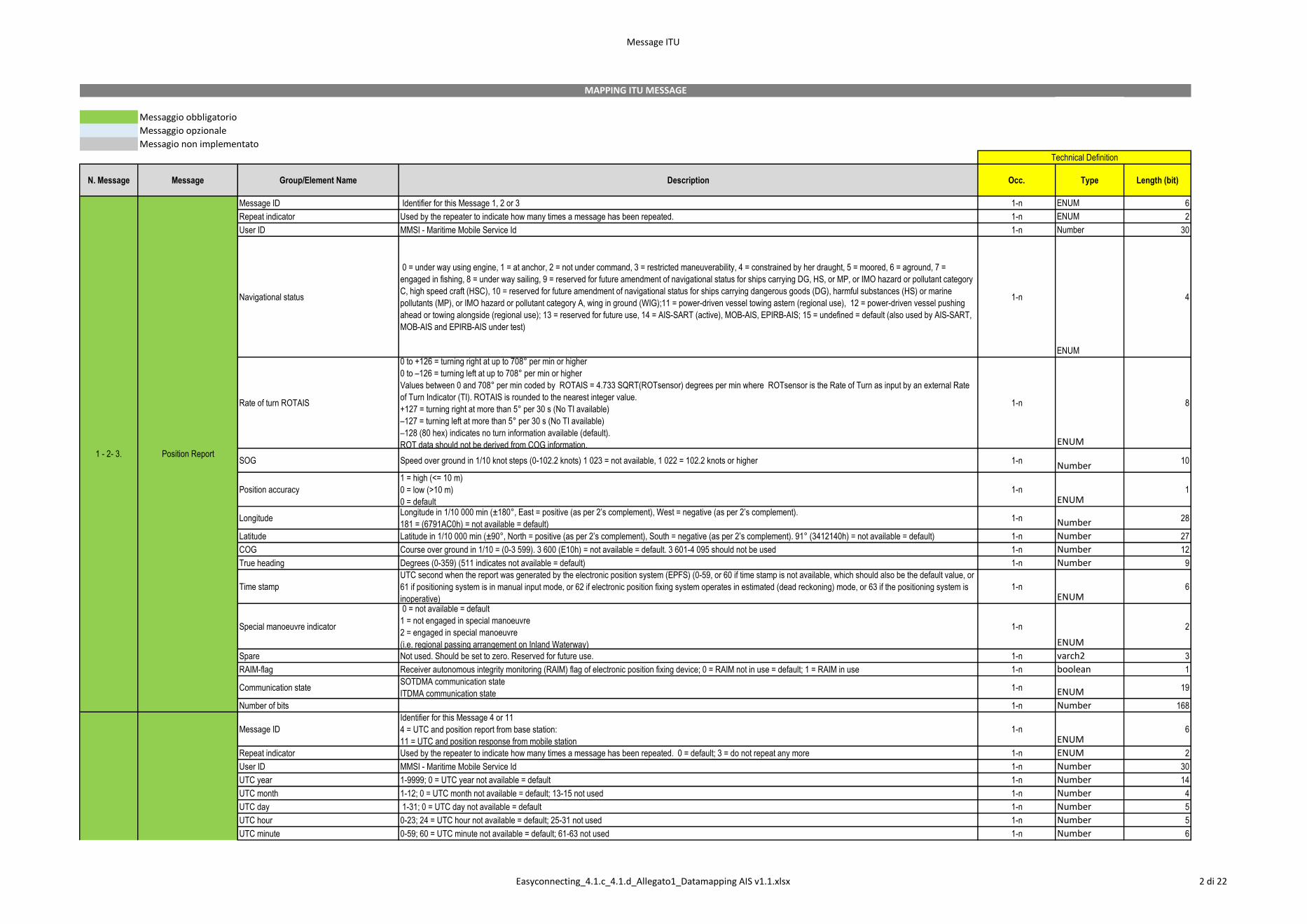
Message ITU
Messaggio obbligatorio
Messaggio opzionale
Messagio non implementato
N. Message Message Group/Element Name Description Occ. Type Length (bit)
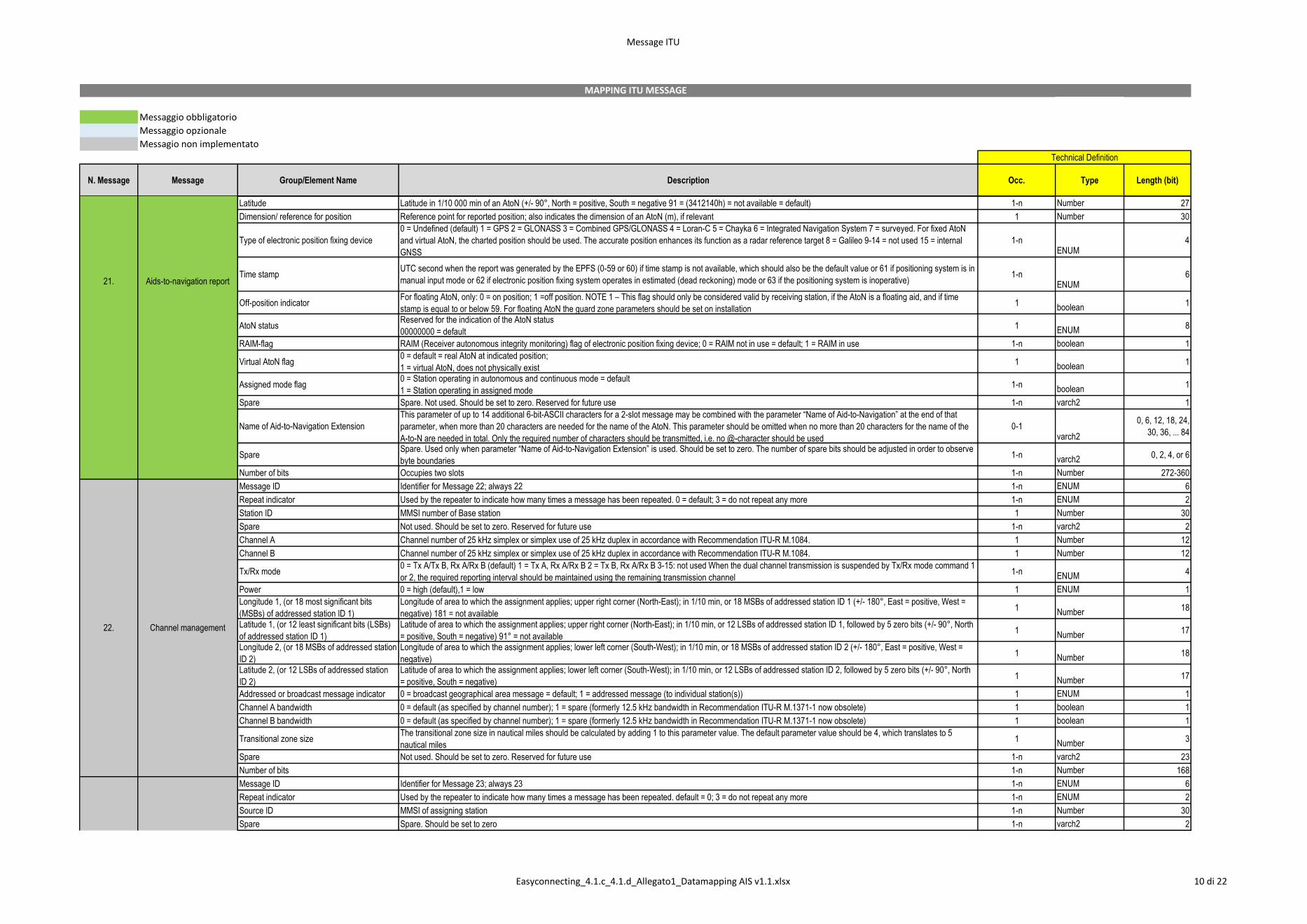
Message ID Identifier for this Message 1, 2 or 3 1-n ENUM 6
Repeat indicator Used by the repeater to indicate how many times a message has been repeated. 1-n ENUM 2
User ID MMSI - Maritime Mobile Service Id 1-n Number 30
Navigational status
0 = under way using engine, 1 = at anchor, 2 = not under command, 3 = restricted maneuverability, 4 = constrained by her draught, 5 = moored, 6 = aground, 7 =
engaged in fishing, 8 = under way sailing, 9 = reserved for future amendment of navigational status for ships carrying DG, HS, or MP, or IMO hazard or pollutant category
C, high speed craft (HSC), 10 = reserved for future amendment of navigational status for ships carrying dangerous goods (DG), harmful substances (HS) or marine
pollutants (MP), or IMO hazard or pollutant category A, wing in ground (WIG);11 = power-driven vessel towing astern (regional use), 12 = power-driven vessel pushing
ahead or towing alongside (regional use); 13 = reserved for future use, 14 = AIS-SART (active), MOB-AIS, EPIRB-AIS; 15 = undefined = default (also used by AIS-SART,
MOB-AIS and EPIRB-AIS under test)
1-n
ENUM
4
Rate of turn ROTAIS
0 to +126 = turning right at up to 708° per min or higher
0 to –126 = turning left at up to 708° per min or higher
Values between 0 and 708° per min coded by ROTAIS = 4.733 SQRT(ROTsensor) degrees per min where ROTsensor is the Rate of Turn as input by an external Rate
of Turn Indicator (TI). ROTAIS is rounded to the nearest integer value.
+127 = turning right at more than 5° per 30 s (No TI available)
–127 = turning left at more than 5° per 30 s (No TI available)
–128 (80 hex) indicates no turn information available (default).
ROT data should not be derived from COG information.
1-n
ENUM
8
SOG Speed over ground in 1/10 knot steps (0-102.2 knots) 1 023 = not available, 1 022 = 102.2 knots or higher 1-nNumber
10
Position accuracy
1 = high (<= 10 m)
0 = low (>10 m)
0 = default
1-nENUM
1
Longitude Longitude in 1/10 000 min (±180°, East = positive (as per 2’s complement), West = negative (as per 2’s complement).
181 = (6791AC0h) = not available = default)1-n Number 28
Latitude Latitude in 1/10 000 min (±90°, North = positive (as per 2’s complement), South = negative (as per 2’s complement). 91° (3412140h) = not available = default) 1-n Number 27
COG Course over ground in 1/10 = (0-3 599). 3 600 (E10h) = not available = default. 3 601-4 095 should not be used 1-n Number 12
True heading Degrees (0-359) (511 indicates not available = default) 1-n Number 9
Time stamp
UTC second when the report was generated by the electronic position system (EPFS) (0-59, or 60 if time stamp is not available, which should also be the default value, or
61 if positioning system is in manual input mode, or 62 if electronic position fixing system operates in estimated (dead reckoning) mode, or 63 if the positioning system is
inoperative)
1-nENUM
6
Special manoeuvre indicator
0 = not available = default
1 = not engaged in special manoeuvre
2 = engaged in special manoeuvre
(i.e. regional passing arrangement on Inland Waterway)
1-n
ENUM
2
Spare Not used. Should be set to zero. Reserved for future use. 1-n varch2 3
RAIM-flag Receiver autonomous integrity monitoring (RAIM) flag of electronic position fixing device; 0 = RAIM not in use = default; 1 = RAIM in use 1-n boolean 1
Communication stateSOTDMA communication state
ITDMA communication state1-n ENUM 19
Number of bits 1-n Number 168
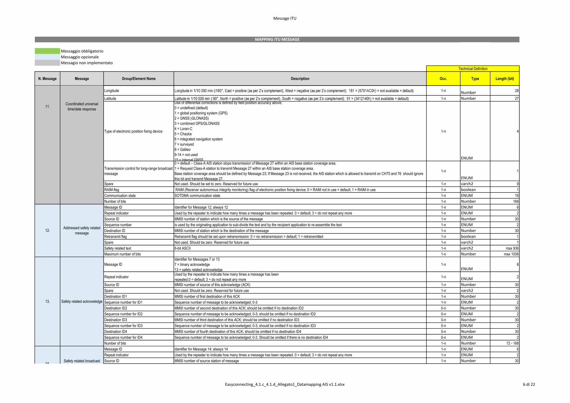
Message ID
Identifier for this Message 4 or 11
4 = UTC and position report from base station:
11 = UTC and position response from mobile station
1-nENUM
6
Repeat indicator Used by the repeater to indicate how many times a message has been repeated. 0 = default; 3 = do not repeat any more 1-n ENUM 2
User ID MMSI - Maritime Mobile Service Id 1-n Number 30
UTC year 1-9999; 0 = UTC year not available = default 1-n Number 14
UTC month 1-12; 0 = UTC month not available = default; 13-15 not used 1-n Number 4
UTC day 1-31; 0 = UTC day not available = default 1-n Number 5
UTC hour 0-23; 24 = UTC hour not available = default; 25-31 not used 1-n Number 5
UTC minute 0-59; 60 = UTC minute not available = default; 61-63 not used 1-n Number 6
Technical Definition
1 - 2- 3. Position Report
4. Base station Report
MAPPING ITU MESSAGE
Easyconnecting_4.1.c_4.1.d_Allegato1_Datamapping AIS v1.1.xlsx 2 di 22
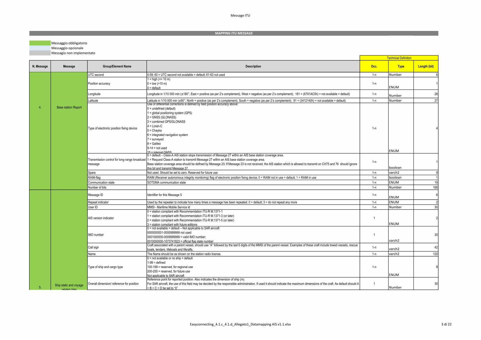
Message ITU
Messaggio obbligatorio
Messaggio opzionale
Messagio non implementato
N. Message Message Group/Element Name Description Occ. Type Length (bit)
Technical Definition
MAPPING ITU MESSAGE
UTC second 0-59; 60 = UTC second not available = default; 61-63 not used 1-n Number 6
Position accuracy
1 = high (<= 10 m)
0 = low (>10 m)
0 = default
1-nENUM
1
Longitude Longitude in 1/10 000 min (±180°, East = positive (as per 2’s complement), West = negative (as per 2’s complement); 181 = (6791AC0h) = not available = default) 1-n Number 28
Latitude Latitude in 1/10 000 min (±90°, North = positive (as per 2’s complement), South = negative (as per 2’s complement); 91 = (3412140h) = not available = default) 1-n Number 27
Type of electronic position fixing device
Use of differential corrections is defined by field position accuracy above:
0 = undefined (default)
1 = global positioning system (GPS)
2 = GNSS (GLONASS)
3 = combined GPS/GLONASS
4 = Loran-C
5 = Chayka
6 = integrated navigation system
7 = surveyed
8 = Galileo
9-14 = not used
15 = internal GNSS
1-n
ENUM
4
Transmission control for long-range broadcast
message
0 = default – Class-A AIS station stops transmission of Message 27 within an AIS base station coverage area.
1 = Request Class-A station to transmit Message 27 within an AIS base station coverage area.
Base station coverage area should be defined by Message 23; If Message 23 is not received, the AIS station which is allowed to transmit on CH75 and 76 should ignore
this bit and transmit Message 27.
1-n
boolean
1
Spare Not used. Should be set to zero. Reserved for future use 1-n varch2 9
RAIM-flag RAIM (Receiver autonomous integrity monitoring) flag of electronic position fixing device; 0 = RAIM not in use = default; 1 = RAIM in use 1-n boolean 1
Communication state SOTDMA communication state 1-n ENUM 19
Number of bits 1-n Number 168
Message ID Identifier for this Message 5 1-nENUM
6
Repeat indicator Used by the repeater to indicate how many times a message has been repeated. 0 = default; 3 = do not repeat any more 1-n ENUM 2
User ID MMSI - Maritime Mobile Service Id 1-n Number 30
AIS version indicator
0 = station compliant with Recommendation ITU-R M.1371-1
1 = station compliant with Recommendation ITU-R M.1371-3 (or later)
2 = station compliant with Recommendation ITU-R M.1371-5 (or later)
3 = station compliant with future editions
1
ENUM
2
IMO number
0 = not available = default – Not applicable to SAR aircraft
0000000001-0000999999 not used
0001000000-0009999999 = valid IMO number;
0010000000-1073741823 = official flag state number
1
varch2
30
Call sign Craft associated with a parent vessel, should use “A” followed by the last 6 digits of the MMSI of the parent vessel. Examples of these craft include towed vessels, rescue
boats, tenders, lifeboats and liferafts. 1-n varch2 42
Name The Name should be as shown on the station radio license. 1-n varch2 120
Type of ship and cargo type
0 = not available or no ship = default
1-99 = defined
100-199 = reserved, for regional use
200-255 = reserved, for future use
Not applicable to SAR aircraft
1-n
ENUM
8
Overall dimension/ reference for position
Reference point for reported position. Also indicates the dimension of ship (m).
For SAR aircraft, the use of this field may be decided by the responsible administration. If used it should indicate the maximum dimensions of the craft. As default should A
= B = C = D be set to “0”
1Number
305.
Ship static and voyage
related data
4. Base station Report
Easyconnecting_4.1.c_4.1.d_Allegato1_Datamapping AIS v1.1.xlsx 3 di 22
Message ITU
Messaggio obbligatorio
Messaggio opzionale
Messagio non implementato
N. Message Message Group/Element Name Description Occ. Type Length (bit)
Technical Definition
MAPPING ITU MESSAGE
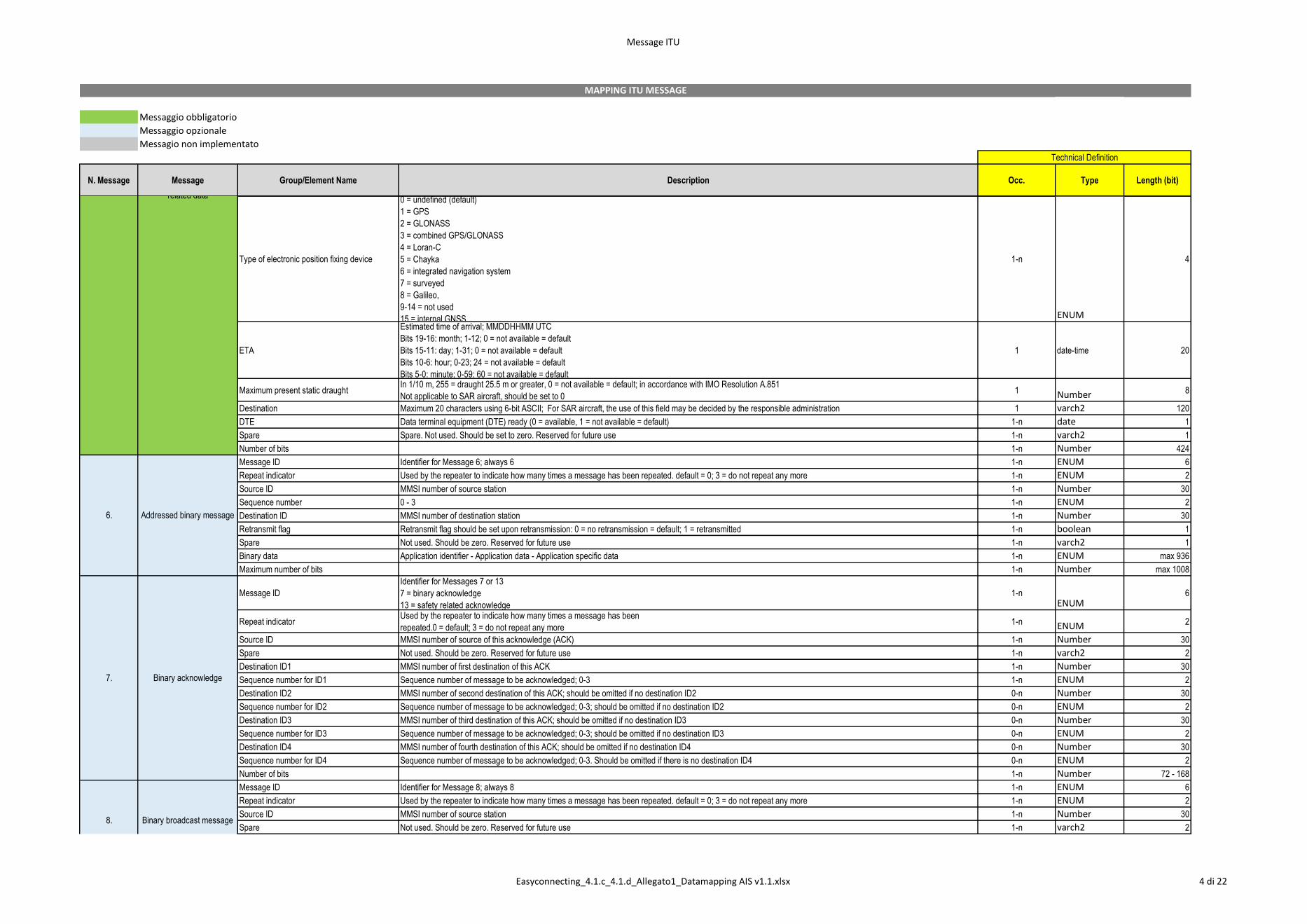
Type of electronic position fixing device
0 = undefined (default)
1 = GPS
2 = GLONASS
3 = combined GPS/GLONASS
4 = Loran-C
5 = Chayka
6 = integrated navigation system
7 = surveyed
8 = Galileo,
9-14 = not used
15 = internal GNSS
1-n
ENUM
4
ETA
Estimated time of arrival; MMDDHHMM UTC
Bits 19-16: month; 1-12; 0 = not available = default
Bits 15-11: day; 1-31; 0 = not available = default
Bits 10-6: hour; 0-23; 24 = not available = default
Bits 5-0: minute; 0-59; 60 = not available = default
1 date-time 20
Maximum present static draught In 1/10 m, 255 = draught 25.5 m or greater, 0 = not available = default; in accordance with IMO Resolution A.851
Not applicable to SAR aircraft, should be set to 0 1 Number 8
Destination Maximum 20 characters using 6-bit ASCII; For SAR aircraft, the use of this field may be decided by the responsible administration 1 varch2 120
DTE Data terminal equipment (DTE) ready (0 = available, 1 = not available = default) 1-n date 1
Spare Spare. Not used. Should be set to zero. Reserved for future use 1-n varch2 1
Number of bits 1-n Number 424
Message ID Identifier for Message 6; always 6 1-n ENUM 6
Repeat indicator Used by the repeater to indicate how many times a message has been repeated. default = 0; 3 = do not repeat any more 1-n ENUM 2
Source ID MMSI number of source station 1-n Number 30
Sequence number 0 - 3 1-n ENUM 2
Destination ID MMSI number of destination station 1-n Number 30
Retransmit flag Retransmit flag should be set upon retransmission: 0 = no retransmission = default; 1 = retransmitted 1-n boolean 1
Spare Not used. Should be zero. Reserved for future use 1-n varch2 1
Binary data Application identifier - Application data - Application specific data 1-n ENUM max 936
Maximum number of bits 1-n Number max 1008
Message ID
Identifier for Messages 7 or 13
7 = binary acknowledge
13 = safety related acknowledge
1-nENUM
6
Repeat indicatorUsed by the repeater to indicate how many times a message has been
repeated.0 = default; 3 = do not repeat any more1-n ENUM 2
Source ID MMSI number of source of this acknowledge (ACK) 1-n Number 30
Spare Not used. Should be zero. Reserved for future use 1-n varch2 2
Destination ID1 MMSI number of first destination of this ACK 1-n Number 30
Sequence number for ID1 Sequence number of message to be acknowledged; 0-3 1-n ENUM 2
Destination ID2 MMSI number of second destination of this ACK; should be omitted if no destination ID2 0-n Number 30
Sequence number for ID2 Sequence number of message to be acknowledged; 0-3; should be omitted if no destination ID2 0-n ENUM 2
Destination ID3 MMSI number of third destination of this ACK; should be omitted if no destination ID3 0-n Number 30
Sequence number for ID3 Sequence number of message to be acknowledged; 0-3; should be omitted if no destination ID3 0-n ENUM 2
Destination ID4 MMSI number of fourth destination of this ACK; should be omitted if no destination ID4 0-n Number 30
Sequence number for ID4 Sequence number of message to be acknowledged; 0-3. Should be omitted if there is no destination ID4 0-n ENUM 2
Number of bits 1-n Number 72 - 168
Message ID Identifier for Message 8; always 8 1-n ENUM 6
Repeat indicator Used by the repeater to indicate how many times a message has been repeated. default = 0; 3 = do not repeat any more 1-n ENUM 2
Source ID MMSI number of source station 1-n Number 30
Spare Not used. Should be zero. Reserved for future use 1-n varch2 2
5.Ship static and voyage
related data
6. Addressed binary message
7. Binary acknowledge
8. Binary broadcast message
Easyconnecting_4.1.c_4.1.d_Allegato1_Datamapping AIS v1.1.xlsx 4 di 22
Message ITU
Messaggio obbligatorio
Messaggio opzionale
Messagio non implementato
N. Message Message Group/Element Name Description Occ. Type Length (bit)
Technical Definition
MAPPING ITU MESSAGE
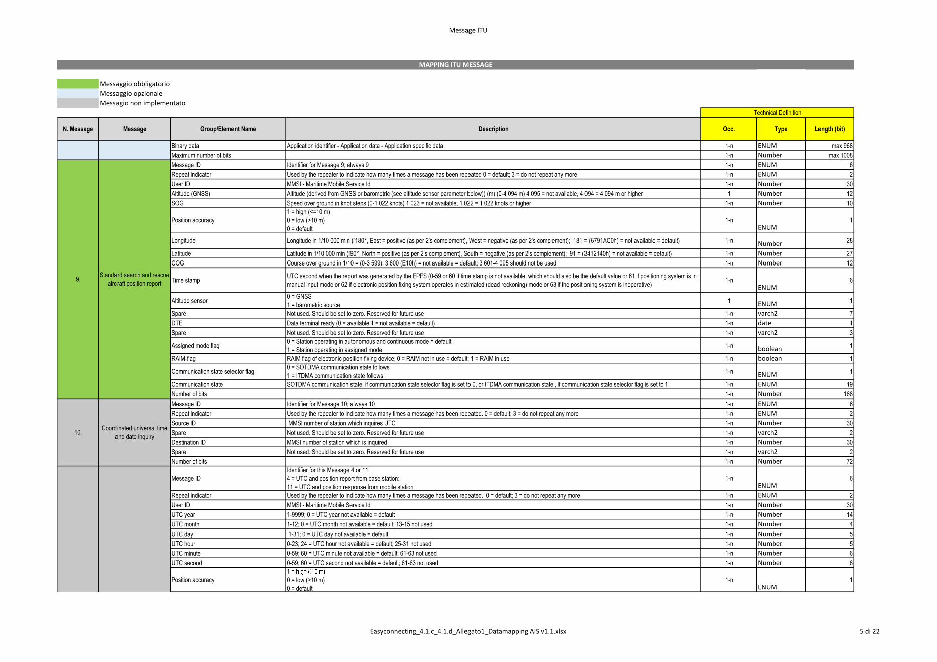
Binary data Application identifier - Application data - Application specific data 1-n ENUM max 968
Maximum number of bits 1-n Number max 1008
Message ID Identifier for Message 9; always 9 1-n ENUM 6
Repeat indicator Used by the repeater to indicate how many times a message has been repeated 0 = default; 3 = do not repeat any more 1-n ENUM 2
User ID MMSI - Maritime Mobile Service Id 1-n Number 30
Altitude (GNSS) Altitude (derived from GNSS or barometric (see altitude sensor parameter below)) (m) (0-4 094 m) 4 095 = not available, 4 094 = 4 094 m or higher 1 Number 12
SOG Speed over ground in knot steps (0-1 022 knots) 1 023 = not available, 1 022 = 1 022 knots or higher 1-n Number 10
Position accuracy
1 = high (<=10 m)
0 = low (>10 m)
0 = default
1-nENUM
1
Longitude 1-n Number 28
Latitude 1-n Number 27
COG Course over ground in 1/10 = (0-3 599). 3 600 (E10h) = not available = default; 3 601-4 095 should not be used 1-n Number 12
Time stamp UTC second when the report was generated by the EPFS (0-59 or 60 if time stamp is not available, which should also be the default value or 61 if positioning system is in
manual input mode or 62 if electronic position fixing system operates in estimated (dead reckoning) mode or 63 if the positioning system is inoperative) 1-n
ENUM6
Altitude sensor0 = GNSS
1 = barometric source 1 ENUM 1
Spare Not used. Should be set to zero. Reserved for future use 1-n varch2 7
DTE Data terminal ready (0 = available 1 = not available = default) 1-n date 1
Spare Not used. Should be set to zero. Reserved for future use 1-n varch2 3
Assigned mode flag 0 = Station operating in autonomous and continuous mode = default
1 = Station operating in assigned mode 1-n boolean 1
RAIM-flag RAIM flag of electronic position fixing device; 0 = RAIM not in use = default; 1 = RAIM in use 1-n boolean 1
Communication state selector flag 0 = SOTDMA communication state follows
1 = ITDMA communication state follows1-n ENUM 1
Communication state SOTDMA communication state, if communication state selector flag is set to 0, or ITDMA communication state , if communication state selector flag is set to 1 1-n ENUM 19
Number of bits 1-n Number 168
Message ID Identifier for Message 10; always 10 1-n ENUM 6
Repeat indicator Used by the repeater to indicate how many times a message has been repeated. 0 = default; 3 = do not repeat any more 1-n ENUM 2
Source ID MMSI number of station which inquires UTC 1-n Number 30
Spare Not used. Should be set to zero. Reserved for future use 1-n varch2 2
Destination ID MMSI number of station which is inquired 1-n Number 30
Spare Not used. Should be set to zero. Reserved for future use 1-n varch2 2
Number of bits 1-n Number 72
Message ID
Identifier for this Message 4 or 11
4 = UTC and position report from base station:
11 = UTC and position response from mobile station
1-nENUM
6
Repeat indicator Used by the repeater to indicate how many times a message has been repeated. 0 = default; 3 = do not repeat any more 1-n ENUM 2
User ID MMSI - Maritime Mobile Service Id 1-n Number 30
UTC year 1-9999; 0 = UTC year not available = default 1-n Number 14
UTC month 1-12; 0 = UTC month not available = default; 13-15 not used 1-n Number 4
UTC day 1-31; 0 = UTC day not available = default 1-n Number 5
UTC hour 0-23; 24 = UTC hour not available = default; 25-31 not used 1-n Number 5
UTC minute 0-59; 60 = UTC minute not available = default; 61-63 not used 1-n Number 6
UTC second 0-59; 60 = UTC second not available = default; 61-63 not used 1-n Number 6
Position accuracy 0 = low (>10 m)
0 = default
1-nENUM
1
8. Binary broadcast message
9.Standard search and rescue
aircraft position report
10.Coordinated universal time
and date inquiry
11.Coordinated universal
time/date response Easyconnecting_4.1.c_4.1.d_Allegato1_Datamapping AIS v1.1.xlsx 5 di 22
Message ITU
Messaggio obbligatorio
Messaggio opzionale
Messagio non implementato
N. Message Message Group/Element Name Description Occ. Type Length (bit)
Technical Definition
MAPPING ITU MESSAGE
Longitude 1-n Number 28
Latitude 1-n Number 27
Type of electronic position fixing device
Use of differential corrections is defined by field position accuracy above:
0 = undefined (default)
1 = global positioning system (GPS)
2 = GNSS (GLONASS)
3 = combined GPS/GLONASS
4 = Loran-C
5 = Chayka
6 = integrated navigation system
7 = surveyed
8 = Galileo
9-14 = not used
15 = internal GNSS
1-n
ENUM
4
Transmission control for long-range broadcast
message
0 = default – Class-A AIS station stops transmission of Message 27 within an AIS base station coverage area.
1 = Request Class-A station to transmit Message 27 within an AIS base station coverage area.
Base station coverage area should be defined by Message 23; If Message 23 is not received, the AIS station which is allowed to transmit on CH75 and 76 should ignore
this bit and transmit Message 27.
1-n
ENUM
1
Spare Not used. Should be set to zero. Reserved for future use 1-n varch2 9
RAIM-flag RAIM (Receiver autonomous integrity monitoring) flag of electronic position fixing device; 0 = RAIM not in use = default; 1 = RAIM in use 1-n boolean 1
Communication state SOTDMA communication state 1-n ENUM 19
Number of bits 1-n Number 168
Message ID Identifier for Message 12; always 12 1-n ENUM 6
Repeat indicator Used by the repeater to indicate how many times a message has been repeated. 0 = default; 3 = do not repeat any more 1-n ENUM 2
Source ID MMSI number of station which is the source of the message 1-n Number 30
Sequence number is used by the originating application to sub-divide the text and by the recipient application to re-assemble the text 1-n ENUM 2
Destination ID MMSI number of station which is the destination of the message 1-n Number 30
Retransmit flag Retransmit flag should be set upon retransmission: 0 = no retransmission = default; 1 = retransmitted 1-n boolean 1
Spare Not used. Should be zero. Reserved for future use 1-n varch2 1
Safety related text 6-bit ASCII 1-n varch2 max 936
Maximum number of bits 1-n Number max 1008
Message ID
Identifier for Messages 7 or 13
7 = binary acknowledge
13 = safety related acknowledge
1-nENUM
6
Repeat indicatorUsed by the repeater to indicate how many times a message has been
repeated.0 = default; 3 = do not repeat any more1-n ENUM 2
Source ID MMSI number of source of this acknowledge (ACK) 1-n Number 30
Spare Not used. Should be zero. Reserved for future use 1-n varch2 2
Destination ID1 MMSI number of first destination of this ACK 1-n Number 30
Sequence number for ID1 Sequence number of message to be acknowledged; 0-3 1-n ENUM 2
Destination ID2 MMSI number of second destination of this ACK; should be omitted if no destination ID2 0-n Number 30
Sequence number for ID2 Sequence number of message to be acknowledged; 0-3; should be omitted if no destination ID2 0-n ENUM 2
Destination ID3 MMSI number of third destination of this ACK; should be omitted if no destination ID3 0-n Number 30
Sequence number for ID3 Sequence number of message to be acknowledged; 0-3; should be omitted if no destination ID3 0-n ENUM 2
Destination ID4 MMSI number of fourth destination of this ACK; should be omitted if no destination ID4 0-n Number 30
Sequence number for ID4 Sequence number of message to be acknowledged; 0-3. Should be omitted if there is no destination ID4 0-n ENUM 2
Number of bits 1-n Number 72 - 168
Message ID Identifier for Message 14; always 14 1-n ENUM 6
Repeat indicator Used by the repeater to indicate how many times a message has been repeated. 0 = default; 3 = do not repeat any more 1-n ENUM 2
Source ID MMSI number of source station of message 1-n Number 30
11.Coordinated universal
time/date response
12.Addressed safety related
message
13. Safety related acknowledge
14.Safety related broadcast
message
Easyconnecting_4.1.c_4.1.d_Allegato1_Datamapping AIS v1.1.xlsx 6 di 22
Message ITU
Messaggio obbligatorio
Messaggio opzionale
Messagio non implementato
N. Message Message Group/Element Name Description Occ. Type Length (bit)
Technical Definition
MAPPING ITU MESSAGE
Spare Not used. Should be set to zero. Reserved for future use 1-n varch2 2
Safety related text 6-bit ASCII 1-n varch2 max 968
Maximum number of bits 1-n Number max 1008
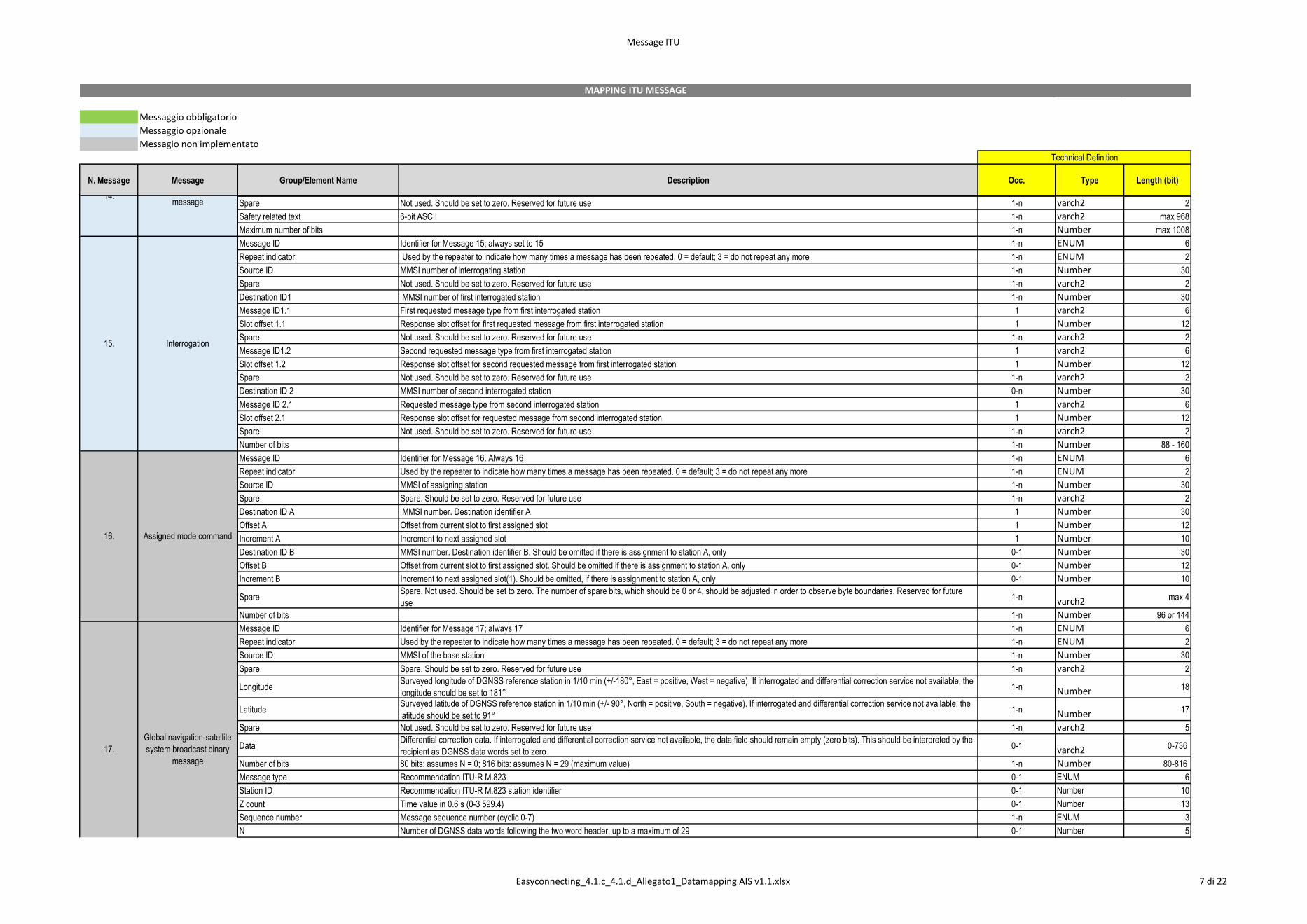
Message ID Identifier for Message 15; always set to 15 1-n ENUM 6
Repeat indicator Used by the repeater to indicate how many times a message has been repeated. 0 = default; 3 = do not repeat any more 1-n ENUM 2
Source ID MMSI number of interrogating station 1-n Number 30
Spare Not used. Should be set to zero. Reserved for future use 1-n varch2 2
Destination ID1 MMSI number of first interrogated station 1-n Number 30
Message ID1.1 First requested message type from first interrogated station 1 varch2 6
Slot offset 1.1 Response slot offset for first requested message from first interrogated station 1 Number 12
Spare Not used. Should be set to zero. Reserved for future use 1-n varch2 2
Message ID1.2 Second requested message type from first interrogated station 1 varch2 6
Slot offset 1.2 Response slot offset for second requested message from first interrogated station 1 Number 12
Spare Not used. Should be set to zero. Reserved for future use 1-n varch2 2
Destination ID 2 MMSI number of second interrogated station 0-n Number 30
Message ID 2.1 Requested message type from second interrogated station 1 varch2 6
Slot offset 2.1 Response slot offset for requested message from second interrogated station 1 Number 12
Spare Not used. Should be set to zero. Reserved for future use 1-n varch2 2
Number of bits 1-n Number 88 - 160
Message ID Identifier for Message 16. Always 16 1-n ENUM 6
Repeat indicator Used by the repeater to indicate how many times a message has been repeated. 0 = default; 3 = do not repeat any more 1-n ENUM 2
Source ID MMSI of assigning station 1-n Number 30
Spare Spare. Should be set to zero. Reserved for future use 1-n varch2 2
Destination ID A MMSI number. Destination identifier A 1 Number 30
Offset A Offset from current slot to first assigned slot 1 Number 12
Increment A Increment to next assigned slot 1 Number 10
Destination ID B MMSI number. Destination identifier B. Should be omitted if there is assignment to station A, only 0-1 Number 30
Offset B Offset from current slot to first assigned slot. Should be omitted if there is assignment to station A, only 0-1 Number 12
Increment B Increment to next assigned slot(1). Should be omitted, if there is assignment to station A, only 0-1 Number 10
SpareSpare. Not used. Should be set to zero. The number of spare bits, which should be 0 or 4, should be adjusted in order to observe byte boundaries. Reserved for future
use1-n varch2 max 4
Number of bits 1-n Number 96 or 144
Message ID Identifier for Message 17; always 17 1-n ENUM 6
Repeat indicator Used by the repeater to indicate how many times a message has been repeated. 0 = default; 3 = do not repeat any more 1-n ENUM 2
Source ID MMSI of the base station 1-n Number 30
Spare Spare. Should be set to zero. Reserved for future use 1-n varch2 2
Longitude Surveyed longitude of DGNSS reference station in 1/10 min (+/-180°, East = positive, West = negative). If interrogated and differential correction service not available, the
longitude should be set to 181° 1-n Number 18
Latitude Surveyed latitude of DGNSS reference station in 1/10 min (+/- 90°, North = positive, South = negative). If interrogated and differential correction service not available, the
latitude should be set to 91° 1-n Number 17
Spare Not used. Should be set to zero. Reserved for future use 1-n varch2 5
Data Differential correction data. If interrogated and differential correction service not available, the data field should remain empty (zero bits). This should be interpreted by the
recipient as DGNSS data words set to zero 0-1 varch2 0-736
Number of bits 80 bits: assumes N = 0; 816 bits: assumes N = 29 (maximum value) 1-n Number 80-816
Message type Recommendation ITU-R M.823 0-1 ENUM 6
Station ID Recommendation ITU-R M.823 station identifier 0-1 Number 10
Z count Time value in 0.6 s (0-3 599.4) 0-1 Number 13
Sequence number Message sequence number (cyclic 0-7) 1-n ENUM 3
N Number of DGNSS data words following the two word header, up to a maximum of 29 0-1 Number 5
14.Safety related broadcast
message
15. Interrogation
16. Assigned mode command
17.
Global navigation-satellite
system broadcast binary
message
Easyconnecting_4.1.c_4.1.d_Allegato1_Datamapping AIS v1.1.xlsx 7 di 22
Message ITU
Messaggio obbligatorio
Messaggio opzionale
Messagio non implementato
N. Message Message Group/Element Name Description Occ. Type Length (bit)
Technical Definition
MAPPING ITU MESSAGE
Health Reference station health (specified in Recommendation ITU-R M.823) 0-1 ENUM 3
DGNSS data word DGNSS message data words excluding parity 0-1 varch2 N = 24
Number of bits Assuming N = 29 (the maximum value) 1-n Number 736
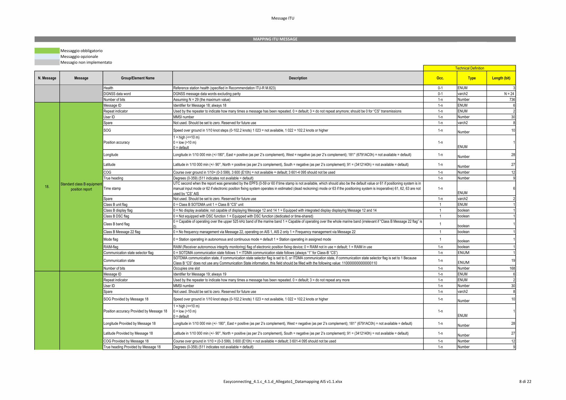
Message ID Identifier for Message 18; always 18 1-n ENUM 6
Repeat indicator Used by the repeater to indicate how many times a message has been repeated. 0 = default; 3 = do not repeat anymore; should be 0 for “CS” transmissions 1-n ENUM 2
User ID MMSI number 1-n Number 30
Spare Not used. Should be set to zero. Reserved for future use 1-n varch2 8
SOG Speed over ground in 1/10 knot steps (0-102.2 knots) 1 023 = not available, 1 022 = 102.2 knots or higher 1-n Number 10
Position accuracy
1 = high (<=10 m)
0 = low (>10 m)
0 = default
1-nENUM
1
Longitude Longitude in 1/10 000 min (+/-180°, East = positive (as per 2’s complement), West = negative (as per 2’s complement); 181° (6791AC0h) = not available = default) 1-nNumber
28
Latitude Latitude in 1/10 000 min (+/- 90°, North = positive (as per 2’s complement), South = negative (as per 2’s complement); 91 = (3412140h) = not available = default) 1-nNumber
27
COG Course over ground in 1/10= (0-3 599). 3 600 (E10h) = not available = default; 3 601-4 095 should not be used 1-n Number 12
True heading Degrees (0-359) (511 indicates not available = default) 1-n Number 9
Time stamp
UTC second when the report was generated by the EPFS (0-59 or 60 if time stamp is not available, which should also be the default value or 61 if positioning system is in
manual input mode or 62 if electronic position fixing system operates in estimated (dead reckoning) mode or 63 if the positioning system is inoperative) 61, 62, 63 are not
used by “CS” AIS
1-nENUM
6
Spare Not used. Should be set to zero. Reserved for future use 1-n varch2 2
Class B unit flag 0 = Class B SOTDMA unit 1 = Class B “CS” unit 1 ENUM 1
Class B display flag 0 = No display available; not capable of displaying Message 12 and 14 1 = Equipped with integrated display displaying Message 12 and 14 1 boolean 1
Class B DSC flag 0 = Not equipped with DSC function 1 = Equipped with DSC function (dedicated or time-shared) 1 boolean 1
Class B band flag 0 = Capable of operating over the upper 525 kHz band of the marine band 1 = Capable of operating over the whole marine band (irrelevant if “Class B Message 22 flag” is
0) 1
boolean1
Class B Message 22 flag 0 = No frequency management via Message 22, operating on AIS 1, AIS 2 only 1 = Frequency management via Message 22 1 boolean 1
Mode flag 0 = Station operating in autonomous and continuous mode = default 1 = Station operating in assigned mode 1 boolean 1
RAIM-flag RAIM (Receiver autonomous integrity monitoring) flag of electronic position fixing device; 0 = RAIM not in use = default; 1 = RAIM in use 1-n boolean 1
Communication state selector flag 0 = SOTDMA communication state follows 1 = ITDMA communication state follows (always “1” for Class-B “CS”) 1-n ENUM 1
Communication state SOTDMA communication state, if communication state selector flag is set to 0, or ITDMA communication state, if communication state selector flag is set to 1 Because
Class B “CS” does not use any Communication State information, this field should be filled with the following value: 1100000000000000110 1-n ENUM 19
Number of bits Occupies one slot 1-n Number 168
Message ID Identifier for Message 19; always 19 1-n ENUM 6
Repeat indicator Used by the repeater to indicate how many times a message has been repeated. 0 = default; 3 = do not repeat any more 1-n ENUM 2
User ID MMSI number 1-n Number 30
Spare Not used. Should be set to zero. Reserved for future use 1-n varch2 8
SOG Provided by Message 18 Speed over ground in 1/10 knot steps (0-102.2 knots) 1 023 = not available, 1 022 = 102.2 knots or higher 1-n Number 10
Position accuracy Provided by Message 18
1 = high (<=10 m)
0 = low (>10 m)
0 = default
1-nENUM
1
Longitude Provided by Message 18 Longitude in 1/10 000 min (+/- 180°, East = positive (as per 2’s complement), West = negative (as per 2’s complement); 181° (6791AC0h) = not available = default) 1-nNumber
28
Latitude Provided by Message 18 Latitude in 1/10 000 min (+/- 90°, North = positive (as per 2’s complement), South = negative (as per 2’s complement); 91 = (3412140h) = not available = default) 1-nNumber
27
COG Provided by Message 18 Course over ground in 1/10 = (0-3 599). 3 600 (E10h) = not available = default; 3 601-4 095 should not be used 1-n Number 12
True heading Provided by Message 18 Degrees (0-359) (511 indicates not available = default) 1-n Number 9
17.
Global navigation-satellite
system broadcast binary
message
18.Standard class B equipment
position report
19.Extended class B
equipment position report
Easyconnecting_4.1.c_4.1.d_Allegato1_Datamapping AIS v1.1.xlsx 8 di 22
Message ITU
Messaggio obbligatorio
Messaggio opzionale
Messagio non implementato
N. Message Message Group/Element Name Description Occ. Type Length (bit)
Technical Definition
MAPPING ITU MESSAGE
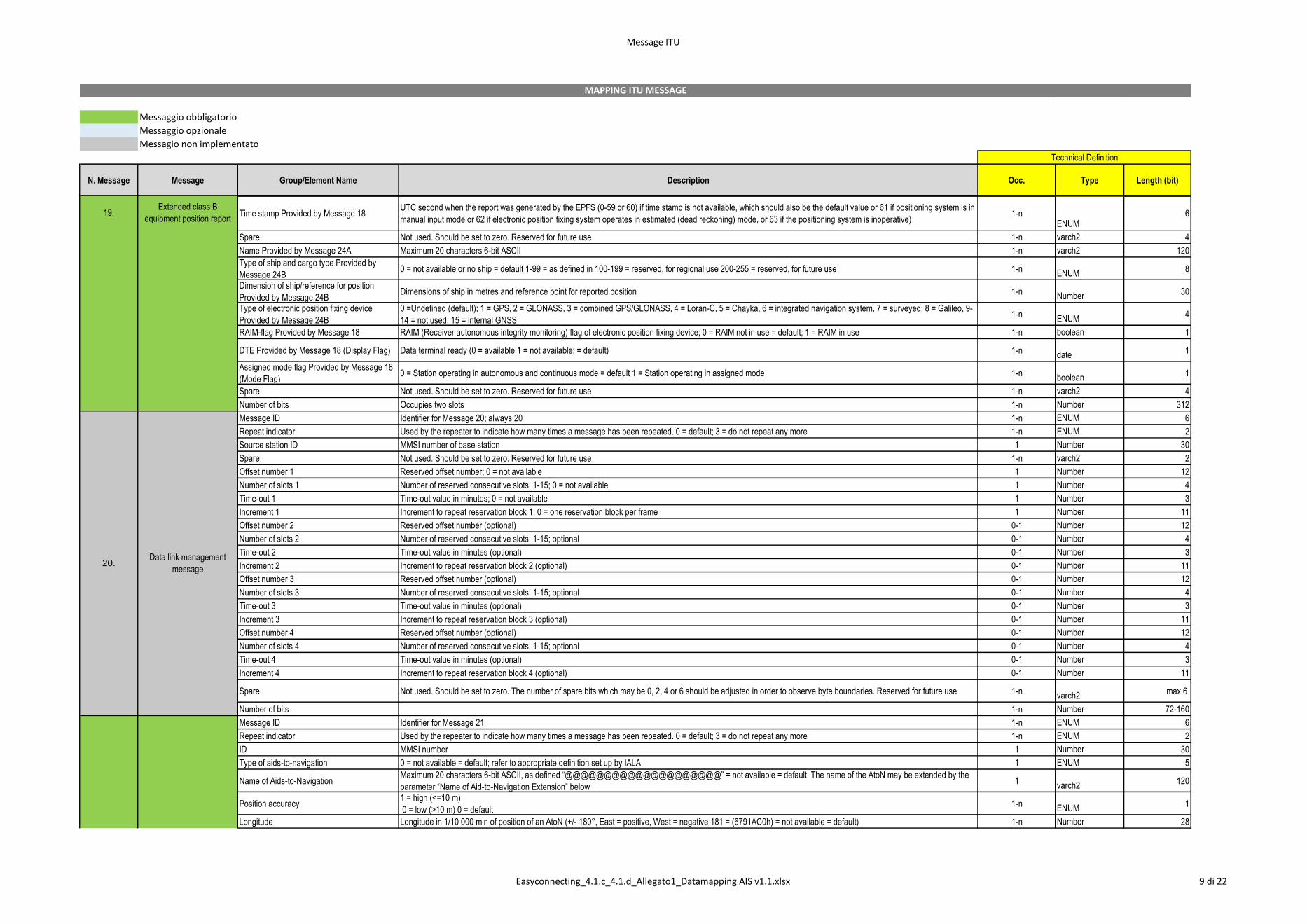
Time stamp Provided by Message 18 UTC second when the report was generated by the EPFS (0-59 or 60) if time stamp is not available, which should also be the default value or 61 if positioning system is in
manual input mode or 62 if electronic position fixing system operates in estimated (dead reckoning) mode, or 63 if the positioning system is inoperative) 1-n
ENUM6
Spare Not used. Should be set to zero. Reserved for future use 1-n varch2 4
Name Provided by Message 24A Maximum 20 characters 6-bit ASCII 1-n varch2 120
Type of ship and cargo type Provided by
Message 24B 0 = not available or no ship = default 1-99 = as defined in 100-199 = reserved, for regional use 200-255 = reserved, for future use 1-n
ENUM8
Dimension of ship/reference for position
Provided by Message 24B Dimensions of ship in metres and reference point for reported position 1-n
Number30
Type of electronic position fixing device
Provided by Message 24B
0 =Undefined (default); 1 = GPS, 2 = GLONASS, 3 = combined GPS/GLONASS, 4 = Loran-C, 5 = Chayka, 6 = integrated navigation system, 7 = surveyed; 8 = Galileo, 9-
14 = not used, 15 = internal GNSS 1-n
ENUM4
RAIM-flag Provided by Message 18 RAIM (Receiver autonomous integrity monitoring) flag of electronic position fixing device; 0 = RAIM not in use = default; 1 = RAIM in use 1-n boolean 1
DTE Provided by Message 18 (Display Flag) Data terminal ready (0 = available 1 = not available; = default) 1-ndate
1
Assigned mode flag Provided by Message 18
(Mode Flag) 0 = Station operating in autonomous and continuous mode = default 1 = Station operating in assigned mode 1-n
boolean1
Spare Not used. Should be set to zero. Reserved for future use 1-n varch2 4
Number of bits Occupies two slots 1-n Number 312
Message ID Identifier for Message 20; always 20 1-n ENUM 6
Repeat indicator Used by the repeater to indicate how many times a message has been repeated. 0 = default; 3 = do not repeat any more 1-n ENUM 2
Source station ID MMSI number of base station 1 Number 30
Spare Not used. Should be set to zero. Reserved for future use 1-n varch2 2
Offset number 1 Reserved offset number; 0 = not available 1 Number 12
Number of slots 1 Number of reserved consecutive slots: 1-15; 0 = not available 1 Number 4
Time-out 1 Time-out value in minutes; 0 = not available 1 Number 3
Increment 1 Increment to repeat reservation block 1; 0 = one reservation block per frame 1 Number 11
Offset number 2 Reserved offset number (optional) 0-1 Number 12
Number of slots 2 Number of reserved consecutive slots: 1-15; optional 0-1 Number 4
Time-out 2 Time-out value in minutes (optional) 0-1 Number 3
Increment 2 Increment to repeat reservation block 2 (optional) 0-1 Number 11
Offset number 3 Reserved offset number (optional) 0-1 Number 12
Number of slots 3 Number of reserved consecutive slots: 1-15; optional 0-1 Number 4
Time-out 3 Time-out value in minutes (optional) 0-1 Number 3
Increment 3 Increment to repeat reservation block 3 (optional) 0-1 Number 11
Offset number 4 Reserved offset number (optional) 0-1 Number 12
Number of slots 4 Number of reserved consecutive slots: 1-15; optional 0-1 Number 4
Time-out 4 Time-out value in minutes (optional) 0-1 Number 3
Increment 4 Increment to repeat reservation block 4 (optional) 0-1 Number 11
Spare Not used. Should be set to zero. The number of spare bits which may be 0, 2, 4 or 6 should be adjusted in order to observe byte boundaries. Reserved for future use 1-nvarch2
max 6
Number of bits 1-n Number 72-160
Message ID Identifier for Message 21 1-n ENUM 6
Repeat indicator Used by the repeater to indicate how many times a message has been repeated. 0 = default; 3 = do not repeat any more 1-n ENUM 2
ID MMSI number 1 Number 30
Type of aids-to-navigation 0 = not available = default; refer to appropriate definition set up by IALA 1 ENUM 5
Name of Aids-to-Navigation Maximum 20 characters 6-bit ASCII, as defined “@@@@@@@@@@@@@@@@@@@@” = not available = default. The name of the AtoN may be extended by the
parameter “Name of Aid-to-Navigation Extension” below 1
varch2120
Position accuracy 1 = high (<=10 m)
0 = low (>10 m) 0 = default 1-n
ENUM1
Longitude Longitude in 1/10 000 min of position of an AtoN (+/- 180°, East = positive, West = negative 181 = (6791AC0h) = not available = default) 1-n Number 28
19.Extended class B
equipment position report
20.Data link management
message
21. Aids-to-navigation report
Easyconnecting_4.1.c_4.1.d_Allegato1_Datamapping AIS v1.1.xlsx 9 di 22
Message ITU
Messaggio obbligatorio
Messaggio opzionale
Messagio non implementato
N. Message Message Group/Element Name Description Occ. Type Length (bit)
Technical Definition
MAPPING ITU MESSAGE
Latitude Latitude in 1/10 000 min of an AtoN (+/- 90°, North = positive, South = negative 91 = (3412140h) = not available = default) 1-n Number 27
Dimension/ reference for position Reference point for reported position; also indicates the dimension of an AtoN (m), if relevant 1 Number 30
Type of electronic position fixing device
0 = Undefined (default) 1 = GPS 2 = GLONASS 3 = Combined GPS/GLONASS 4 = Loran-C 5 = Chayka 6 = Integrated Navigation System 7 = surveyed. For fixed AtoN
and virtual AtoN, the charted position should be used. The accurate position enhances its function as a radar reference target 8 = Galileo 9-14 = not used 15 = internal
GNSS
1-nENUM
4
Time stamp UTC second when the report was generated by the EPFS (0-59 or 60) if time stamp is not available, which should also be the default value or 61 if positioning system is in
manual input mode or 62 if electronic position fixing system operates in estimated (dead reckoning) mode or 63 if the positioning system is inoperative) 1-n
ENUM6
Off-position indicator For floating AtoN, only: 0 = on position; 1 =off position. NOTE 1 – This flag should only be considered valid by receiving station, if the AtoN is a floating aid, and if time
stamp is equal to or below 59. For floating AtoN the guard zone parameters should be set on installation 1
boolean1
AtoN status Reserved for the indication of the AtoN status
00000000 = default 1
ENUM8
RAIM-flag RAIM (Receiver autonomous integrity monitoring) flag of electronic position fixing device; 0 = RAIM not in use = default; 1 = RAIM in use 1-n boolean 1
Virtual AtoN flag 0 = default = real AtoN at indicated position;
1 = virtual AtoN, does not physically exist 1
boolean1
Assigned mode flag 0 = Station operating in autonomous and continuous mode = default
1 = Station operating in assigned mode 1-n
boolean1
Spare Spare. Not used. Should be set to zero. Reserved for future use 1-n varch2 1
Name of Aid-to-Navigation Extension
This parameter of up to 14 additional 6-bit-ASCII characters for a 2-slot message may be combined with the parameter “Name of Aid-to-Navigation” at the end of that
parameter, when more than 20 characters are needed for the name of the AtoN. This parameter should be omitted when no more than 20 characters for the name of the
A-to-N are needed in total. Only the required number of characters should be transmitted, i.e. no @-character should be used
0-1varch2
0, 6, 12, 18, 24,
30, 36, ... 84
Spare Spare. Used only when parameter “Name of Aid-to-Navigation Extension” is used. Should be set to zero. The number of spare bits should be adjusted in order to observe
byte boundaries 1-n
varch20, 2, 4, or 6
Number of bits Occupies two slots 1-n Number 272-360
Message ID Identifier for Message 22; always 22 1-n ENUM 6
Repeat indicator Used by the repeater to indicate how many times a message has been repeated. 0 = default; 3 = do not repeat any more 1-n ENUM 2
Station ID MMSI number of Base station 1 Number 30
Spare Not used. Should be set to zero. Reserved for future use 1-n varch2 2
Channel A Channel number of 25 kHz simplex or simplex use of 25 kHz duplex in accordance with Recommendation ITU-R M.1084. 1 Number 12
Channel B Channel number of 25 kHz simplex or simplex use of 25 kHz duplex in accordance with Recommendation ITU-R M.1084. 1 Number 12
Tx/Rx mode 0 = Tx A/Tx B, Rx A/Rx B (default) 1 = Tx A, Rx A/Rx B 2 = Tx B, Rx A/Rx B 3-15: not used When the dual channel transmission is suspended by Tx/Rx mode command 1
or 2, the required reporting interval should be maintained using the remaining transmission channel 1-n
ENUM4
Power 0 = high (default),1 = low 1 ENUM 1
Longitude 1, (or 18 most significant bits
(MSBs) of addressed station ID 1)
Longitude of area to which the assignment applies; upper right corner (North-East); in 1/10 min, or 18 MSBs of addressed station ID 1 (+/- 180°, East = positive, West =
negative) 181 = not available1
Number18
Latitude 1, (or 12 least significant bits (LSBs)
of addressed station ID 1)
Latitude of area to which the assignment applies; upper right corner (North-East); in 1/10 min, or 12 LSBs of addressed station ID 1, followed by 5 zero bits (+/- 90°, North
= positive, South = negative) 91° = not available1
Number17
Longitude 2, (or 18 MSBs of addressed station
ID 2)
Longitude of area to which the assignment applies; lower left corner (South-West); in 1/10 min, or 18 MSBs of addressed station ID 2 (+/- 180°, East = positive, West =
negative)1
Number18
Latitude 2, (or 12 LSBs of addressed station
ID 2)
Latitude of area to which the assignment applies; lower left corner (South-West); in 1/10 min, or 12 LSBs of addressed station ID 2, followed by 5 zero bits (+/- 90°, North
= positive, South = negative)1
Number17
Addressed or broadcast message indicator 0 = broadcast geographical area message = default; 1 = addressed message (to individual station(s)) 1 ENUM 1
Channel A bandwidth 0 = default (as specified by channel number); 1 = spare (formerly 12.5 kHz bandwidth in Recommendation ITU-R M.1371-1 now obsolete) 1 boolean 1
Channel B bandwidth 0 = default (as specified by channel number); 1 = spare (formerly 12.5 kHz bandwidth in Recommendation ITU-R M.1371-1 now obsolete) 1 boolean 1
Transitional zone size The transitional zone size in nautical miles should be calculated by adding 1 to this parameter value. The default parameter value should be 4, which translates to 5
nautical miles1
Number3
Spare Not used. Should be set to zero. Reserved for future use 1-n varch2 23
Number of bits 1-n Number 168
Message ID Identifier for Message 23; always 23 1-n ENUM 6
Repeat indicator Used by the repeater to indicate how many times a message has been repeated. default = 0; 3 = do not repeat any more 1-n ENUM 2
Source ID MMSI of assigning station 1-n Number 30
Spare Spare. Should be set to zero 1-n varch2 2
21. Aids-to-navigation report
22. Channel management
23.Group assignment
command
Easyconnecting_4.1.c_4.1.d_Allegato1_Datamapping AIS v1.1.xlsx 10 di 22

Message ITU
Messaggio obbligatorio
Messaggio opzionale
Messagio non implementato
N. Message Message Group/Element Name Description Occ. Type Length (bit)
Technical Definition
MAPPING ITU MESSAGE
Longitude 1 Longitude of area to which the group assignment applies; upper right corner (north-east); in 1/10 min (+/- 180°, East = positive, West = negative) 1 Number 18
Latitude 1 Latitude of area to which the group assignment applies; upper right corner (north-east); in 1/10 min (+/-90°, North = positive, South = negative) 1 Number 17
Longitude 2 Longitude of area to which the group assignment applies; lower left corner (south-west); in 1/10 min (+/-180°, East = positive, West = negative) 1 Number 18
Latitude 2 Latitude of area to which the group assignment applies; lower left corner (south-west); in 1/10 min (+/-90°, North = positive, South = negative) 1 Number 17
Station type
0 = all types of mobiles (default); 1 = Class A mobile stations only; 2 = all types of Class B mobile stations; 3 = SAR airborne mobile station; 4 = Class B “SO” mobile
stations only; 5 = Class B “CS” shipborne mobile station only; 6 = inland waterways; 7 to 9 = regional use; 10 = base station coverage area (see Message 4 and Message
27); 11 to 15 = for future use
1ENUM
4
Type of ship and cargo type 0 = all types (default) 1-99 as defined; 100 -199 reserved for regional use; 200-255 reserved for future use 1-n ENUM 8
Spare Not used. Should be set to zero. Reserved for future use 1-n varch2 22
Tx/Rx mode This parameter commands the respective stations to one of the following modes: 0 = TxA/TxB, RxA/RxB (default); 1 = TxA, RxA/RxB, 2 = TxB, RxA/RxB, 3 = reserved for
future use 1-n
ENUM2
Reporting interval This parameter commands the respective stations to the reporting interval 1 Number 4
Quiet time 0 = default = no quiet time commanded; 1-15 = quiet time of 1 to 15 min 1 ENUM 4
Spare Not used. Should be set to zero. Reserved for future use 1-n varch2 6
Number of bits Occupies one-time period 1-n Number 160
Message ID Identifier for Message 24; always 24 1-n ENUM 6
Repeat indicator Used by the repeater to indicate how many times a message has been repeated. 0 = default; 3 = do not repeat any more 1-n ENUM 2
User ID MMSI number 1-n Number 30
Part number Identifier for the message part number; always 0 for Part A 1 ENUM 2
Name Name of the MMSI-registered vessel. Maximum 20 characters 6-bit ASCII, @@@@@@@@@@@@@@@@@@@@ = not available = default. For SAR aircraft, it
should be set to “SAR AIRCRAFT NNNNNNN” where NNNNNNN equals the aircraft registration number 1-n
varch2120
Number of bits Occupies one-time period 1-n Number 160
Message ID Identifier for Message 24; always 24 1-n ENUM 6
Repeat indicator Used by the repeater to indicate how many times a message has been repeated. 0 = default; 3 = do not repeat any more 1-n ENUM 2
User ID MMSI number 1-n Number 30
Part number Identifier for the message part number; always 1 for Part B 1 ENUM 2
Type of ship and cargo type 0 = not available or no ship = default 1-99 = as defined 100-199 = reserved, for regional use 200-255 = reserved, for future use. Not applicable to SAR aircraft 1-n ENUM 8
Vendor ID Unique identification of the Unit by a number as defined by the manufacturer (option; “@@@@@@@” = not available = default) 1 Number 42
Call sign Call sign of the MMSI-registered vessel. 7 x 6 bit ASCII characters, “@@@@@@@” = not available = default. Craft associated with a parent vessel should use “A”
followed by the last 6 digits of the MMSI of the parent vessel. Examples of these craft include towed vessels, rescue boats, tenders, lifeboats and life rafts. 1-n varch2 42
Dimension of ship/reference for position Dimensions of ship in metres and reference point for reported position. For SAR aircraft, the use of this field may be decided by the responsible administration. If used it
should indicate the maximum dimensions of the craft. As default should A = B = C = D be set to “0”. 1
Number30
Type of electronic position fixing device 0 = Undefined (default); 1 = GPS, 2 = GLONASS, 3 = combined GPS/GLONASS, 4 = Loran-C, 5 = Chayka, 6 = integrated navigation system, 7 = surveyed; 8 = Galileo, 9-
14 = not used, 15 = internal GNSS 1-n
ENUM4
Spare 1-n varch2 2
Number of bits Occupies one-time period 1-n Number 168
Message ID Identifier for Message 25; always 25 1-n ENUM 6
Repeat indicator Used by the repeater to indicate how many times a message has been repeated. default = 0; 3 = do not repeat any more 1-n ENUM 2
Source ID MMSI number of source station 1-n Number 30
Destination indicator 0 = Broadcast (no Destination ID field used) 1 = Addressed (Destination ID uses 30 data bits for MMSI) 1-n ENUM 1
Binary data flag 0 = unstructured binary data (no Application Identifier bits used) 1 = binary data coded as defined by using the 16-bit Application identifier 1-n boolean 1
Destination IDDestination ID (if used). If Destination indicator = 0 (Broadcast); no data bits are needed for the Destination ID. If Destination indicator = 1; 30 bits are used for Destination
ID and spare bits for byte alignment.1-n
ENUM0/30
Spare Spare (if Destination ID used) 1-n varch2 0/2
Binary data Application identifier - Application binary data - Application specific data 1-n
ENUM
Broadcast
Maximum 128
Addressed
Maximum 96
Maximum number of bits Occupies up to 1 slot subject to the length of sub-field message content Class B “CS” mobile AIS stations should not transmit 1-n Number max 168
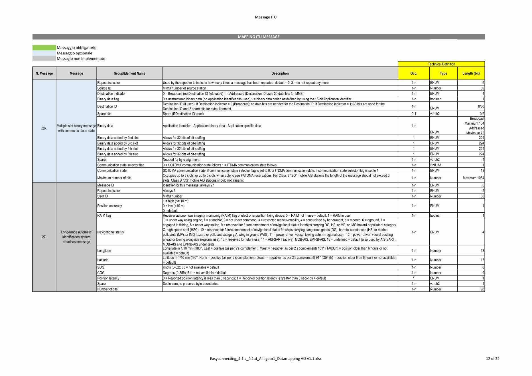
Message ID Identifier for Message 26; always 26 1-n ENUM 6
24.
Static data report - Part A
Static data report - Part B
25. Single slot binary message
26.Multiple slot binary message
with communications state
23.Group assignment
command
Easyconnecting_4.1.c_4.1.d_Allegato1_Datamapping AIS v1.1.xlsx 11 di 22
Message ITU
Messaggio obbligatorio
Messaggio opzionale
Messagio non implementato
N. Message Message Group/Element Name Description Occ. Type Length (bit)
Technical Definition
MAPPING ITU MESSAGE
Repeat indicator Used by the repeater to indicate how many times a message has been repeated. default = 0; 3 = do not repeat any more 1-n ENUM 2
Source ID MMSI number of source station 1-n Number 30
Destination indicator 0 = Broadcast (no Destination ID field used) 1 = Addressed (Destination ID uses 30 data bits for MMSI) 1-n ENUM 1
Binary data flag 0 = unstructured binary data (no Application Identifier bits used) 1 = binary data coded as defined by using the 16-bit Application identifier 1-n boolean 1
Destination IDDestination ID (if used). If Destination indicator = 0 (Broadcast); no data bits are needed for the Destination ID. If Destination indicator = 1; 30 bits are used for the
Destination ID and 2 spare bits for byte alignment.1-n
ENUM0/30
Spare bits Spare (if Destination ID used) 0-1 varch2 0/2
Binary data Application identifier - Application binary data - Application specific data 1-n
ENUM
Broadcast
Maximum 104
Addressed
Maximum 72
Binary data added by 2nd slot Allows for 32 bits of bit-stuffing 1 ENUM 224
Binary data added by 3rd slot Allows for 32 bits of bit-stuffing 1 ENUM 224
Binary data added by 4th slot Allows for 32 bits of bit-stuffing 1 ENUM 224
Binary data added by 5th slot Allows for 32 bits of bit-stuffing 1 ENUM 224
Spare Needed for byte alignment 1-n varch2 4
Communication state selector flag 0 = SOTDMA communication state follows 1 = ITDMA communication state follows 1-n ENUM 1
Communication state SOTDMA communication state, if communication state selector flag is set to 0, or ITDMA communication state, if communication state selector flag is set to 1 1-n ENUM 19
Maximum number of bits Occupies up to 3 slots, or up to 5 slots when able to use FATDMA reservations. For Class B “SO” mobile AIS stations the length of the message should not exceed 3
slots. Class B “CS” mobile AIS stations should not transmit 1-n Number Maximum 1064
Message ID Identifier for this message; always 27 1-n ENUM 6
Repeat indicator Always 3 1-n ENUM 2
User ID MMSI number 1-n Number 30
Position accuracy
1 = high (<= 10 m)
0 = low (>10 m)
0 = default
1-n ENUM 1
RAIM flag Receiver autonomous integrity monitoring (RAIM) flag of electronic position fixing device; 0 = RAIM not in use = default; 1 = RAIM in use 1-n boolean 1
Navigational status
0 = under way using engine, 1 = at anchor, 2 = not under command, 3 = restricted maneuverability, 4 = constrained by her draught, 5 = moored, 6 = aground, 7 =
engaged in fishing, 8 = under way sailing, 9 = reserved for future amendment of navigational status for ships carrying DG, HS, or MP, or IMO hazard or pollutant category
C, high speed craft (HSC), 10 = reserved for future amendment of navigational status for ships carrying dangerous goods (DG), harmful substances (HS) or marine
pollutants (MP), or IMO hazard or pollutant category A, wing in ground (WIG);11 = power-driven vessel towing astern (regional use), 12 = power-driven vessel pushing
ahead or towing alongside (regional use); 13 = reserved for future use, 14 = AIS-SART (active), MOB-AIS, EPIRB-AIS; 15 = undefined = default (also used by AIS-SART,
MOB-AIS and EPIRB-AIS under test)
1-n ENUM 4
Longitude available = default)
1-n Number 18
Latitude = default)
1-n Number 17
SOG Knots (0-62); 63 = not available = default 1-n Number 6
COG Degrees (0-359); 511 = not available = default 1-n Number 9
Position latency 0 = Reported position latency is less than 5 seconds; 1 = Reported position latency is greater than 5 seconds = default 1 ENUM 1
Spare Set to zero, to preserve byte boundaries 1-n varch2 1
Number of bits 1-n Number 96
27.
Long-range automatic
identification system
broadcast message
26.Multiple slot binary message
with communications state
Easyconnecting_4.1.c_4.1.d_Allegato1_Datamapping AIS v1.1.xlsx 12 di 22
DataMapping
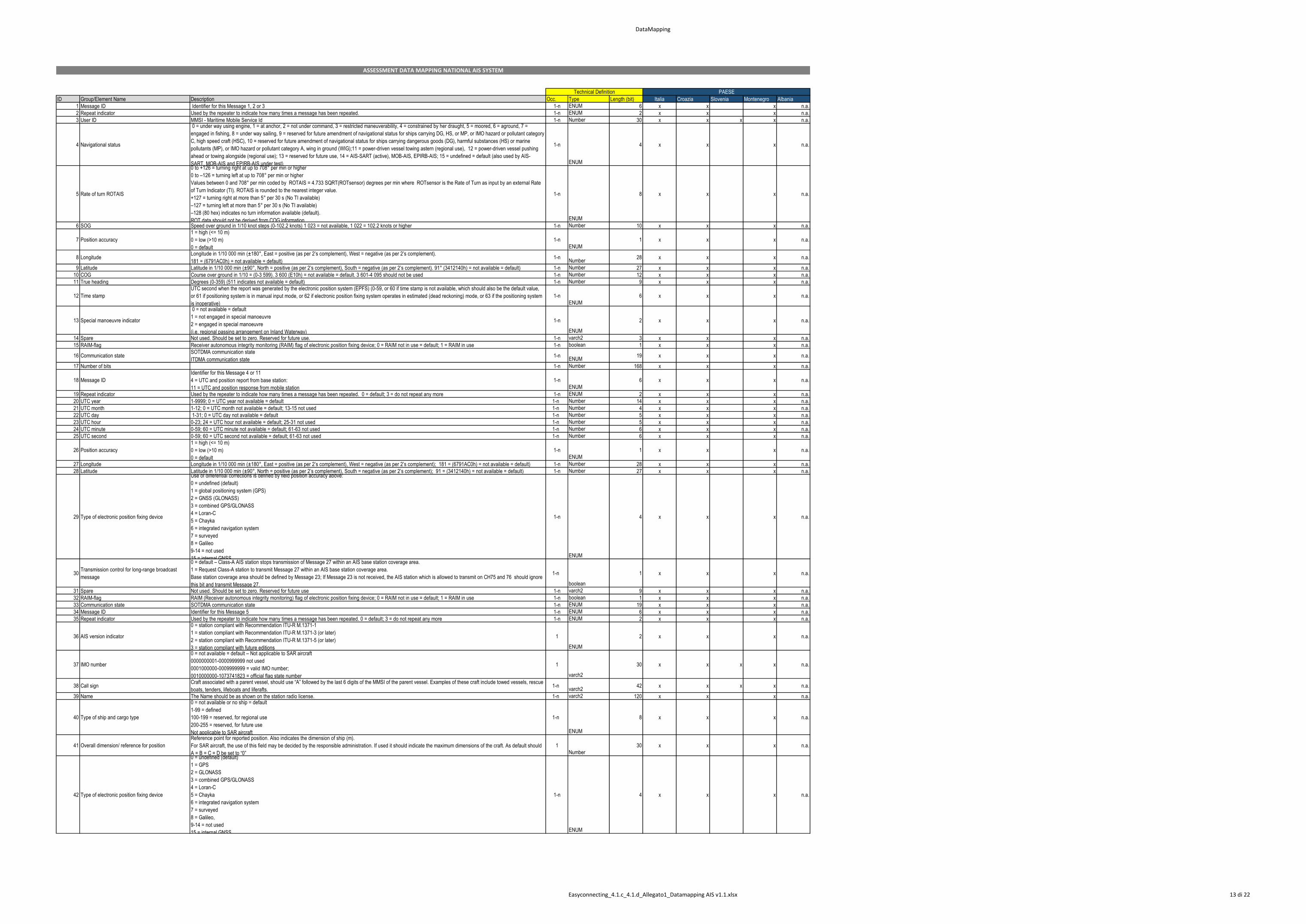
ID Group/Element Name Description Occ. Type Length (bit) Italia Croazia Slovenia Montenegro Albania
1 Message ID Identifier for this Message 1, 2 or 3 1-n ENUM 6 x x x n.a.
2 Repeat indicator Used by the repeater to indicate how many times a message has been repeated. 1-n ENUM 2 x x x n.a.
3 User ID MMSI - Maritime Mobile Service Id 1-n Number 30 x x x x n.a.
4 Navigational status
0 = under way using engine, 1 = at anchor, 2 = not under command, 3 = restricted maneuverability, 4 = constrained by her draught, 5 = moored, 6 = aground, 7 =
engaged in fishing, 8 = under way sailing, 9 = reserved for future amendment of navigational status for ships carrying DG, HS, or MP, or IMO hazard or pollutant category
C, high speed craft (HSC), 10 = reserved for future amendment of navigational status for ships carrying dangerous goods (DG), harmful substances (HS) or marine
pollutants (MP), or IMO hazard or pollutant category A, wing in ground (WIG);11 = power-driven vessel towing astern (regional use), 12 = power-driven vessel pushing
ahead or towing alongside (regional use); 13 = reserved for future use, 14 = AIS-SART (active), MOB-AIS, EPIRB-AIS; 15 = undefined = default (also used by AIS-
SART, MOB-AIS and EPIRB-AIS under test)
1-n
ENUM
4 x x x n.a.
5 Rate of turn ROTAIS
0 to +126 = turning right at up to 708° per min or higher
0 to –126 = turning left at up to 708° per min or higher
Values between 0 and 708° per min coded by ROTAIS = 4.733 SQRT(ROTsensor) degrees per min where ROTsensor is the Rate of Turn as input by an external Rate
of Turn Indicator (TI). ROTAIS is rounded to the nearest integer value.
+127 = turning right at more than 5° per 30 s (No TI available)
–127 = turning left at more than 5° per 30 s (No TI available)
–128 (80 hex) indicates no turn information available (default).
ROT data should not be derived from COG information.
1-n
ENUM
8 x x x n.a.
6 SOG Speed over ground in 1/10 knot steps (0-102.2 knots) 1 023 = not available, 1 022 = 102.2 knots or higher 1-n Number 10 x x x n.a.
7 Position accuracy
1 = high (<= 10 m)
0 = low (>10 m)
0 = default
1-n
ENUM
1 x x x n.a.
8 Longitude Longitude in 1/10 000 min (±180°, East = positive (as per 2’s complement), West = negative (as per 2’s complement).
181 = (6791AC0h) = not available = default)1-n
Number28 x x x n.a.
9 Latitude Latitude in 1/10 000 min (±90°, North = positive (as per 2’s complement), South = negative (as per 2’s complement). 91° (3412140h) = not available = default) 1-n Number 27 x x x n.a.
10 COG Course over ground in 1/10 = (0-3 599). 3 600 (E10h) = not available = default. 3 601-4 095 should not be used 1-n Number 12 x x x n.a.
11 True heading Degrees (0-359) (511 indicates not available = default) 1-n Number 9 x x x n.a.
12 Time stamp
UTC second when the report was generated by the electronic position system (EPFS) (0-59, or 60 if time stamp is not available, which should also be the default value,
or 61 if positioning system is in manual input mode, or 62 if electronic position fixing system operates in estimated (dead reckoning) mode, or 63 if the positioning system
is inoperative)
1-n
ENUM
6 x x x n.a.
13 Special manoeuvre indicator
0 = not available = default
1 = not engaged in special manoeuvre
2 = engaged in special manoeuvre
(i.e. regional passing arrangement on Inland Waterway)
1-n
ENUM
2 x x x n.a.
14 Spare Not used. Should be set to zero. Reserved for future use. 1-n varch2 3 x x x n.a.
15 RAIM-flag Receiver autonomous integrity monitoring (RAIM) flag of electronic position fixing device; 0 = RAIM not in use = default; 1 = RAIM in use 1-n boolean 1 x x x n.a.
16 Communication stateSOTDMA communication state
ITDMA communication state1-n
ENUM19 x x x n.a.
17 Number of bits 1-n Number 168 x x x n.a.
18 Message ID
Identifier for this Message 4 or 11
4 = UTC and position report from base station:
11 = UTC and position response from mobile station
1-n
ENUM
6 x x x n.a.
19 Repeat indicator Used by the repeater to indicate how many times a message has been repeated. 0 = default; 3 = do not repeat any more 1-n ENUM 2 x x x n.a.
20 UTC year 1-9999; 0 = UTC year not available = default 1-n Number 14 x x x n.a.
21 UTC month 1-12; 0 = UTC month not available = default; 13-15 not used 1-n Number 4 x x x n.a.
22 UTC day 1-31; 0 = UTC day not available = default 1-n Number 5 x x x n.a.
23 UTC hour 0-23; 24 = UTC hour not available = default; 25-31 not used 1-n Number 5 x x x n.a.
24 UTC minute 0-59; 60 = UTC minute not available = default; 61-63 not used 1-n Number 6 x x x n.a.
25 UTC second 0-59; 60 = UTC second not available = default; 61-63 not used 1-n Number 6 x x x n.a.
26 Position accuracy
1 = high (<= 10 m)
0 = low (>10 m)
0 = default
1-n
ENUM
1 x x x n.a.
27 Longitude Longitude in 1/10 000 min (±180°, East = positive (as per 2’s complement), West = negative (as per 2’s complement); 181 = (6791AC0h) = not available = default) 1-n Number 28 x x x n.a.
28 Latitude Latitude in 1/10 000 min (±90°, North = positive (as per 2’s complement), South = negative (as per 2’s complement); 91 = (3412140h) = not available = default) 1-n Number 27 x x x n.a.
29 Type of electronic position fixing device
Use of differential corrections is defined by field position accuracy above:
0 = undefined (default)
1 = global positioning system (GPS)
2 = GNSS (GLONASS)
3 = combined GPS/GLONASS
4 = Loran-C
5 = Chayka
6 = integrated navigation system
7 = surveyed
8 = Galileo
9-14 = not used
15 = internal GNSS
1-n
ENUM
4 x x x n.a.
30Transmission control for long-range broadcast
message
0 = default – Class-A AIS station stops transmission of Message 27 within an AIS base station coverage area.
1 = Request Class-A station to transmit Message 27 within an AIS base station coverage area.
Base station coverage area should be defined by Message 23; If Message 23 is not received, the AIS station which is allowed to transmit on CH75 and 76 should ignore
this bit and transmit Message 27.
1-n
boolean
1 x x x n.a.
31 Spare Not used. Should be set to zero. Reserved for future use 1-n varch2 9 x x x n.a.
32 RAIM-flag RAIM (Receiver autonomous integrity monitoring) flag of electronic position fixing device; 0 = RAIM not in use = default; 1 = RAIM in use 1-n boolean 1 x x x n.a.
33 Communication state SOTDMA communication state 1-n ENUM 19 x x x n.a.
34 Message ID Identifier for this Message 5 1-n ENUM 6 x x x n.a.
35 Repeat indicator Used by the repeater to indicate how many times a message has been repeated. 0 = default; 3 = do not repeat any more 1-n ENUM 2 x x x n.a.
36 AIS version indicator
0 = station compliant with Recommendation ITU-R M.1371-1
1 = station compliant with Recommendation ITU-R M.1371-3 (or later)
2 = station compliant with Recommendation ITU-R M.1371-5 (or later)
3 = station compliant with future editions
1
ENUM
2 x x x n.a.
37 IMO number
0 = not available = default – Not applicable to SAR aircraft
0000000001-0000999999 not used
0001000000-0009999999 = valid IMO number;
0010000000-1073741823 = official flag state number
1
varch2
30 x x x x n.a.
38 Call sign Craft associated with a parent vessel, should use “A” followed by the last 6 digits of the MMSI of the parent vessel. Examples of these craft include towed vessels, rescue
boats, tenders, lifeboats and liferafts. 1-n
varch242 x x x x n.a.
39 Name The Name should be as shown on the station radio license. 1-n varch2 120 x x x n.a.
40 Type of ship and cargo type
0 = not available or no ship = default
1-99 = defined
100-199 = reserved, for regional use
200-255 = reserved, for future use
Not applicable to SAR aircraft
1-n
ENUM
8 x x x n.a.
41 Overall dimension/ reference for position
Reference point for reported position. Also indicates the dimension of ship (m).
For SAR aircraft, the use of this field may be decided by the responsible administration. If used it should indicate the maximum dimensions of the craft. As default should
A = B = C = D be set to “0”
1
Number
30 x x x n.a.
42 Type of electronic position fixing device
0 = undefined (default)
1 = GPS
2 = GLONASS
3 = combined GPS/GLONASS
4 = Loran-C
5 = Chayka
6 = integrated navigation system
7 = surveyed
8 = Galileo,
9-14 = not used
15 = internal GNSS
1-n
ENUM
4 x x x n.a.
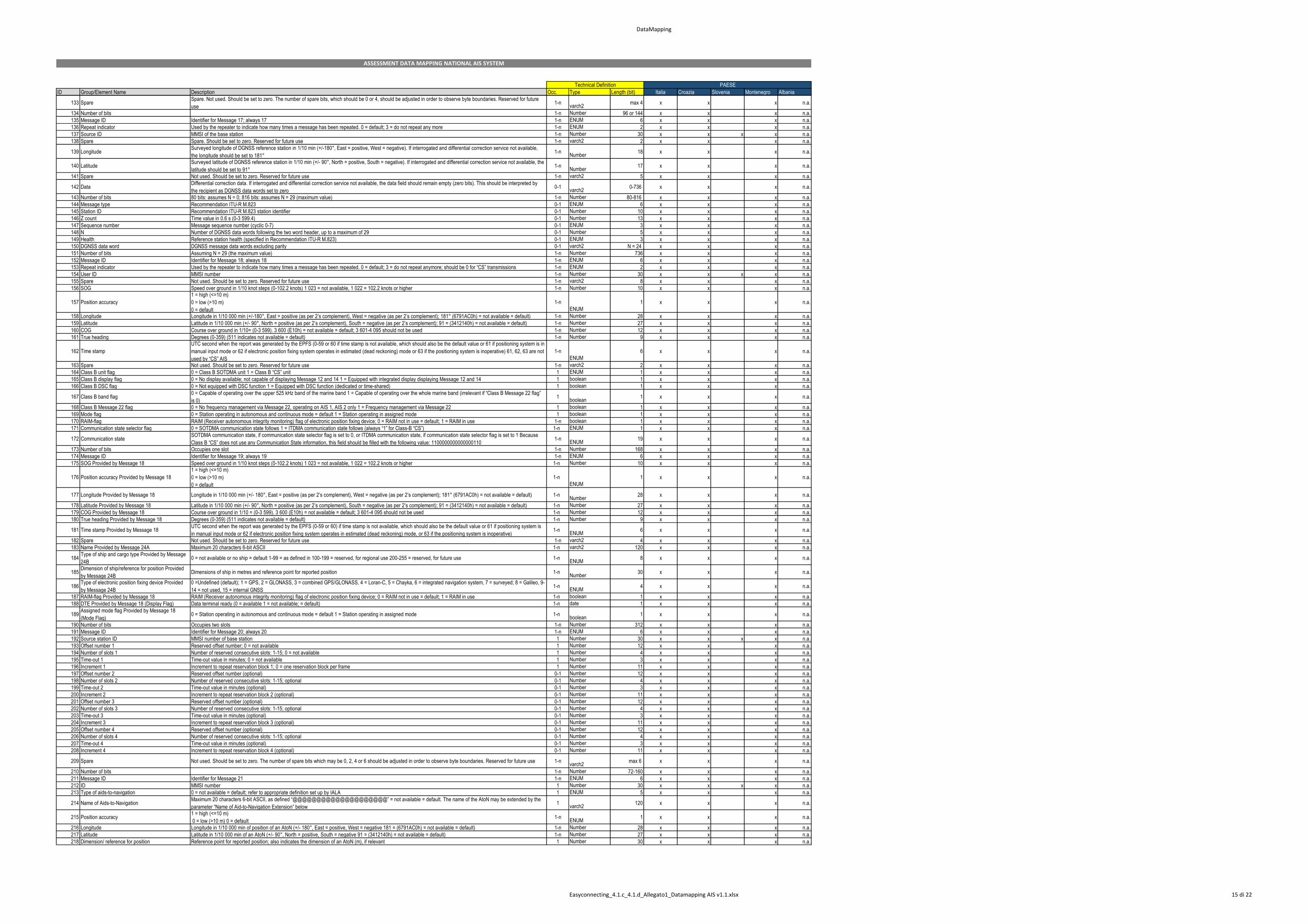
Technical Definition PAESE
ASSESSMENT DATA MAPPING NATIONAL AIS SYSTEM
Easyconnecting_4.1.c_4.1.d_Allegato1_Datamapping AIS v1.1.xlsx 13 di 22
DataMapping
ID Group/Element Name Description Occ. Type Length (bit) Italia Croazia Slovenia Montenegro Albania
Technical Definition PAESE
ASSESSMENT DATA MAPPING NATIONAL AIS SYSTEM
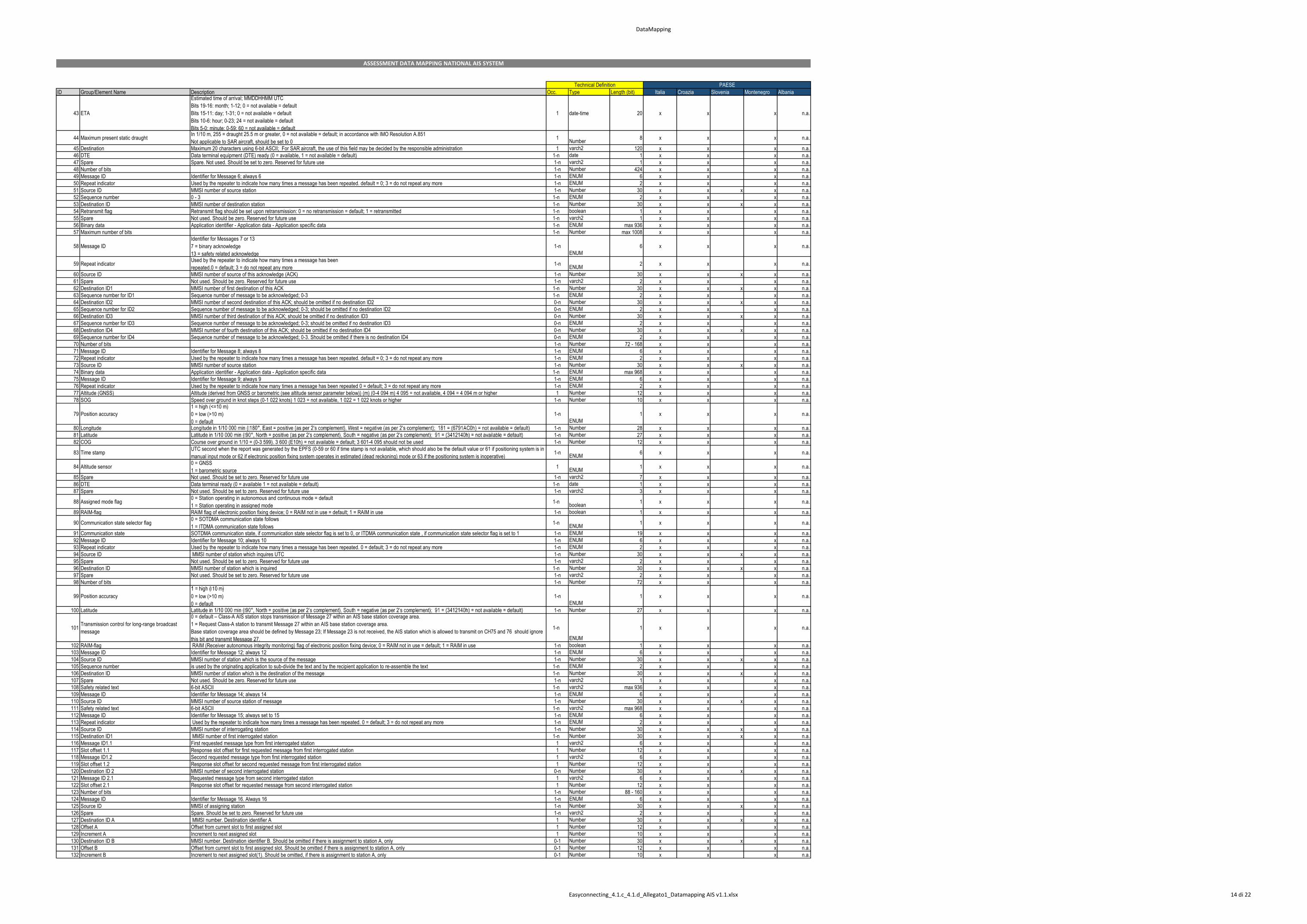
43 ETA
Estimated time of arrival; MMDDHHMM UTC
Bits 19-16: month; 1-12; 0 = not available = default
Bits 15-11: day; 1-31; 0 = not available = default
Bits 10-6: hour; 0-23; 24 = not available = default
Bits 5-0: minute; 0-59; 60 = not available = default
1 date-time 20 x x x n.a.
44 Maximum present static draught In 1/10 m, 255 = draught 25.5 m or greater, 0 = not available = default; in accordance with IMO Resolution A.851
Not applicable to SAR aircraft, should be set to 0 1
Number8 x x x n.a.
45 Destination Maximum 20 characters using 6-bit ASCII; For SAR aircraft, the use of this field may be decided by the responsible administration 1 varch2 120 x x x n.a.
46 DTE Data terminal equipment (DTE) ready (0 = available, 1 = not available = default) 1-n date 1 x x x n.a.
47 Spare Spare. Not used. Should be set to zero. Reserved for future use 1-n varch2 1 x x x n.a.
48 Number of bits 1-n Number 424 x x x n.a.
49 Message ID Identifier for Message 6; always 6 1-n ENUM 6 x x x n.a.
50 Repeat indicator Used by the repeater to indicate how many times a message has been repeated. default = 0; 3 = do not repeat any more 1-n ENUM 2 x x x n.a.
51 Source ID MMSI number of source station 1-n Number 30 x x x x n.a.
52 Sequence number 0 - 3 1-n ENUM 2 x x x n.a.
53 Destination ID MMSI number of destination station 1-n Number 30 x x x x n.a.
54 Retransmit flag Retransmit flag should be set upon retransmission: 0 = no retransmission = default; 1 = retransmitted 1-n boolean 1 x x x n.a.
55 Spare Not used. Should be zero. Reserved for future use 1-n varch2 1 x x x n.a.
56 Binary data Application identifier - Application data - Application specific data 1-n ENUM max 936 x x x n.a.
57 Maximum number of bits 1-n Number max 1008 x x x n.a.
58 Message ID
Identifier for Messages 7 or 13
7 = binary acknowledge
13 = safety related acknowledge
1-n
ENUM
6 x x x n.a.
59 Repeat indicatorUsed by the repeater to indicate how many times a message has been
repeated.0 = default; 3 = do not repeat any more1-n
ENUM2 x x x n.a.
60 Source ID MMSI number of source of this acknowledge (ACK) 1-n Number 30 x x x x n.a.
61 Spare Not used. Should be zero. Reserved for future use 1-n varch2 2 x x x n.a.
62 Destination ID1 MMSI number of first destination of this ACK 1-n Number 30 x x x x n.a.
63 Sequence number for ID1 Sequence number of message to be acknowledged; 0-3 1-n ENUM 2 x x x n.a.
64 Destination ID2 MMSI number of second destination of this ACK; should be omitted if no destination ID2 0-n Number 30 x x x x n.a.
65 Sequence number for ID2 Sequence number of message to be acknowledged; 0-3; should be omitted if no destination ID2 0-n ENUM 2 x x x n.a.
66 Destination ID3 MMSI number of third destination of this ACK; should be omitted if no destination ID3 0-n Number 30 x x x x n.a.
67 Sequence number for ID3 Sequence number of message to be acknowledged; 0-3; should be omitted if no destination ID3 0-n ENUM 2 x x x n.a.
68 Destination ID4 MMSI number of fourth destination of this ACK; should be omitted if no destination ID4 0-n Number 30 x x x x n.a.
69 Sequence number for ID4 Sequence number of message to be acknowledged; 0-3. Should be omitted if there is no destination ID4 0-n ENUM 2 x x x n.a.
70 Number of bits 1-n Number 72 - 168 x x x n.a.
71 Message ID Identifier for Message 8; always 8 1-n ENUM 6 x x x n.a.
72 Repeat indicator Used by the repeater to indicate how many times a message has been repeated. default = 0; 3 = do not repeat any more 1-n ENUM 2 x x x n.a.
73 Source ID MMSI number of source station 1-n Number 30 x x x x n.a.
74 Binary data Application identifier - Application data - Application specific data 1-n ENUM max 968 x x x n.a.
75 Message ID Identifier for Message 9; always 9 1-n ENUM 6 x x x n.a.
76 Repeat indicator Used by the repeater to indicate how many times a message has been repeated 0 = default; 3 = do not repeat any more 1-n ENUM 2 x x x n.a.
77 Altitude (GNSS) Altitude (derived from GNSS or barometric (see altitude sensor parameter below)) (m) (0-4 094 m) 4 095 = not available, 4 094 = 4 094 m or higher 1 Number 12 x x x n.a.
78 SOG Speed over ground in knot steps (0-1 022 knots) 1 023 = not available, 1 022 = 1 022 knots or higher 1-n Number 10 x x x n.a.
79 Position accuracy
1 = high (<=10 m)
0 = low (>10 m)
0 = default
1-n
ENUM
1 x x x n.a.
80 Longitude 1-n Number 28 x x x n.a.
81 Latitude 1-n Number 27 x x x n.a.
82 COG Course over ground in 1/10 = (0-3 599). 3 600 (E10h) = not available = default; 3 601-4 095 should not be used 1-n Number 12 x x x n.a.
83 Time stamp UTC second when the report was generated by the EPFS (0-59 or 60 if time stamp is not available, which should also be the default value or 61 if positioning system is in
manual input mode or 62 if electronic position fixing system operates in estimated (dead reckoning) mode or 63 if the positioning system is inoperative) 1-n
ENUM6 x x x n.a.
84 Altitude sensor0 = GNSS
1 = barometric source 1
ENUM1 x x x n.a.
85 Spare Not used. Should be set to zero. Reserved for future use 1-n varch2 7 x x x n.a.
86 DTE Data terminal ready (0 = available 1 = not available = default) 1-n date 1 x x x n.a.
87 Spare Not used. Should be set to zero. Reserved for future use 1-n varch2 3 x x x n.a.
88 Assigned mode flag 0 = Station operating in autonomous and continuous mode = default
1 = Station operating in assigned mode 1-n
boolean1 x x x n.a.
89 RAIM-flag RAIM flag of electronic position fixing device; 0 = RAIM not in use = default; 1 = RAIM in use 1-n boolean 1 x x x n.a.
90 Communication state selector flag 0 = SOTDMA communication state follows
1 = ITDMA communication state follows1-n
ENUM1 x x x n.a.
91 Communication state SOTDMA communication state, if communication state selector flag is set to 0, or ITDMA communication state , if communication state selector flag is set to 1 1-n ENUM 19 x x x n.a.
92 Message ID Identifier for Message 10; always 10 1-n ENUM 6 x x x n.a.
93 Repeat indicator Used by the repeater to indicate how many times a message has been repeated. 0 = default; 3 = do not repeat any more 1-n ENUM 2 x x x n.a.
94 Source ID MMSI number of station which inquires UTC 1-n Number 30 x x x x n.a.
95 Spare Not used. Should be set to zero. Reserved for future use 1-n varch2 2 x x x n.a.
96 Destination ID MMSI number of station which is inquired 1-n Number 30 x x x x n.a.
97 Spare Not used. Should be set to zero. Reserved for future use 1-n varch2 2 x x x n.a.
98 Number of bits 1-n Number 72 x x x n.a.
99 Position accuracy 0 = low (>10 m)
0 = default
1-n
ENUM
1 x x x n.a.
100 Latitude 1-n Number 27 x x x n.a.
101Transmission control for long-range broadcast
message
0 = default – Class-A AIS station stops transmission of Message 27 within an AIS base station coverage area.
1 = Request Class-A station to transmit Message 27 within an AIS base station coverage area.
Base station coverage area should be defined by Message 23; If Message 23 is not received, the AIS station which is allowed to transmit on CH75 and 76 should ignore
this bit and transmit Message 27.
1-n
ENUM
1 x x x n.a.
102 RAIM-flag RAIM (Receiver autonomous integrity monitoring) flag of electronic position fixing device; 0 = RAIM not in use = default; 1 = RAIM in use 1-n boolean 1 x x x n.a.
103 Message ID Identifier for Message 12; always 12 1-n ENUM 6 x x x n.a.
104 Source ID MMSI number of station which is the source of the message 1-n Number 30 x x x x n.a.
105 Sequence number is used by the originating application to sub-divide the text and by the recipient application to re-assemble the text 1-n ENUM 2 x x x n.a.
106 Destination ID MMSI number of station which is the destination of the message 1-n Number 30 x x x x n.a.
107 Spare Not used. Should be zero. Reserved for future use 1-n varch2 1 x x x n.a.
108 Safety related text 6-bit ASCII 1-n varch2 max 936 x x x n.a.
109 Message ID Identifier for Message 14; always 14 1-n ENUM 6 x x x n.a.
110 Source ID MMSI number of source station of message 1-n Number 30 x x x x n.a.
111 Safety related text 6-bit ASCII 1-n varch2 max 968 x x x n.a.
112 Message ID Identifier for Message 15; always set to 15 1-n ENUM 6 x x x n.a.
113 Repeat indicator Used by the repeater to indicate how many times a message has been repeated. 0 = default; 3 = do not repeat any more 1-n ENUM 2 x x x n.a.
114 Source ID MMSI number of interrogating station 1-n Number 30 x x x x n.a.
115 Destination ID1 MMSI number of first interrogated station 1-n Number 30 x x x x n.a.
116 Message ID1.1 First requested message type from first interrogated station 1 varch2 6 x x x n.a.
117 Slot offset 1.1 Response slot offset for first requested message from first interrogated station 1 Number 12 x x x n.a.
118 Message ID1.2 Second requested message type from first interrogated station 1 varch2 6 x x x n.a.
119 Slot offset 1.2 Response slot offset for second requested message from first interrogated station 1 Number 12 x x x n.a.
120 Destination ID 2 MMSI number of second interrogated station 0-n Number 30 x x x x n.a.
121 Message ID 2.1 Requested message type from second interrogated station 1 varch2 6 x x x n.a.
122 Slot offset 2.1 Response slot offset for requested message from second interrogated station 1 Number 12 x x x n.a.
123 Number of bits 1-n Number 88 - 160 x x x n.a.
124 Message ID Identifier for Message 16. Always 16 1-n ENUM 6 x x x n.a.
125 Source ID MMSI of assigning station 1-n Number 30 x x x x n.a.
126 Spare Spare. Should be set to zero. Reserved for future use 1-n varch2 2 x x x n.a.
127 Destination ID A MMSI number. Destination identifier A 1 Number 30 x x x x n.a.
128 Offset A Offset from current slot to first assigned slot 1 Number 12 x x x n.a.
129 Increment A Increment to next assigned slot 1 Number 10 x x x n.a.
130 Destination ID B MMSI number. Destination identifier B. Should be omitted if there is assignment to station A, only 0-1 Number 30 x x x x n.a.
131 Offset B Offset from current slot to first assigned slot. Should be omitted if there is assignment to station A, only 0-1 Number 12 x x x n.a.
132 Increment B Increment to next assigned slot(1). Should be omitted, if there is assignment to station A, only 0-1 Number 10 x x x n.a.
Easyconnecting_4.1.c_4.1.d_Allegato1_Datamapping AIS v1.1.xlsx 14 di 22
DataMapping
ID Group/Element Name Description Occ. Type Length (bit) Italia Croazia Slovenia Montenegro Albania
Technical Definition PAESE
ASSESSMENT DATA MAPPING NATIONAL AIS SYSTEM
133 SpareSpare. Not used. Should be set to zero. The number of spare bits, which should be 0 or 4, should be adjusted in order to observe byte boundaries. Reserved for future
use1-n
varch2max 4 x x x n.a.
134 Number of bits 1-n Number 96 or 144 x x x n.a.
135 Message ID Identifier for Message 17; always 17 1-n ENUM 6 x x x n.a.
136 Repeat indicator Used by the repeater to indicate how many times a message has been repeated. 0 = default; 3 = do not repeat any more 1-n ENUM 2 x x x n.a.
137 Source ID MMSI of the base station 1-n Number 30 x x x x n.a.
138 Spare Spare. Should be set to zero. Reserved for future use 1-n varch2 2 x x x n.a.
139 Longitude Surveyed longitude of DGNSS reference station in 1/10 min (+/-180°, East = positive, West = negative). If interrogated and differential correction service not available,
the longitude should be set to 181° 1-n
Number18 x x x n.a.
140 Latitude Surveyed latitude of DGNSS reference station in 1/10 min (+/- 90°, North = positive, South = negative). If interrogated and differential correction service not available, the
latitude should be set to 91° 1-n
Number17 x x x n.a.
141 Spare Not used. Should be set to zero. Reserved for future use 1-n varch2 5 x x x n.a.
142 Data Differential correction data. If interrogated and differential correction service not available, the data field should remain empty (zero bits). This should be interpreted by
the recipient as DGNSS data words set to zero 0-1
varch20-736 x x x n.a.
143 Number of bits 80 bits: assumes N = 0; 816 bits: assumes N = 29 (maximum value) 1-n Number 80-816 x x x n.a.
144 Message type Recommendation ITU-R M.823 0-1 ENUM 6 x x x n.a.
145 Station ID Recommendation ITU-R M.823 station identifier 0-1 Number 10 x x x n.a.
146 Z count Time value in 0.6 s (0-3 599.4) 0-1 Number 13 x x x n.a.
147 Sequence number Message sequence number (cyclic 0-7) 0-1 ENUM 3 x x x n.a.
148 N Number of DGNSS data words following the two word header, up to a maximum of 29 0-1 Number 5 x x x n.a.
149 Health Reference station health (specified in Recommendation ITU-R M.823) 0-1 ENUM 3 x x x n.a.
150 DGNSS data word DGNSS message data words excluding parity 0-1 varch2 N = 24 x x x n.a.
151 Number of bits Assuming N = 29 (the maximum value) 1-n Number 736 x x x n.a.
152 Message ID Identifier for Message 18; always 18 1-n ENUM 6 x x x n.a.
153 Repeat indicator Used by the repeater to indicate how many times a message has been repeated. 0 = default; 3 = do not repeat anymore; should be 0 for “CS” transmissions 1-n ENUM 2 x x x n.a.
154 User ID MMSI number 1-n Number 30 x x x x n.a.
155 Spare Not used. Should be set to zero. Reserved for future use 1-n varch2 8 x x x n.a.
156 SOG Speed over ground in 1/10 knot steps (0-102.2 knots) 1 023 = not available, 1 022 = 102.2 knots or higher 1-n Number 10 x x x n.a.
157 Position accuracy
1 = high (<=10 m)
0 = low (>10 m)
0 = default
1-n
ENUM
1 x x x n.a.
158 Longitude Longitude in 1/10 000 min (+/-180°, East = positive (as per 2’s complement), West = negative (as per 2’s complement); 181° (6791AC0h) = not available = default) 1-n Number 28 x x x n.a.
159 Latitude Latitude in 1/10 000 min (+/- 90°, North = positive (as per 2’s complement), South = negative (as per 2’s complement); 91 = (3412140h) = not available = default) 1-n Number 27 x x x n.a.
160 COG Course over ground in 1/10= (0-3 599). 3 600 (E10h) = not available = default; 3 601-4 095 should not be used 1-n Number 12 x x x n.a.
161 True heading Degrees (0-359) (511 indicates not available = default) 1-n Number 9 x x x n.a.
162 Time stamp
UTC second when the report was generated by the EPFS (0-59 or 60 if time stamp is not available, which should also be the default value or 61 if positioning system is in
manual input mode or 62 if electronic position fixing system operates in estimated (dead reckoning) mode or 63 if the positioning system is inoperative) 61, 62, 63 are not
used by “CS” AIS
1-n
ENUM
6 x x x n.a.
163 Spare Not used. Should be set to zero. Reserved for future use 1-n varch2 2 x x x n.a.
164 Class B unit flag 0 = Class B SOTDMA unit 1 = Class B “CS” unit 1 ENUM 1 x x x n.a.
165 Class B display flag 0 = No display available; not capable of displaying Message 12 and 14 1 = Equipped with integrated display displaying Message 12 and 14 1 boolean 1 x x x n.a.
166 Class B DSC flag 0 = Not equipped with DSC function 1 = Equipped with DSC function (dedicated or time-shared) 1 boolean 1 x x x n.a.
167 Class B band flag 0 = Capable of operating over the upper 525 kHz band of the marine band 1 = Capable of operating over the whole marine band (irrelevant if “Class B Message 22 flag”
is 0) 1
boolean1 x x x n.a.
168 Class B Message 22 flag 0 = No frequency management via Message 22, operating on AIS 1, AIS 2 only 1 = Frequency management via Message 22 1 boolean 1 x x x n.a.
169 Mode flag 0 = Station operating in autonomous and continuous mode = default 1 = Station operating in assigned mode 1 boolean 1 x x x n.a.
170 RAIM-flag RAIM (Receiver autonomous integrity monitoring) flag of electronic position fixing device; 0 = RAIM not in use = default; 1 = RAIM in use 1-n boolean 1 x x x n.a.
171 Communication state selector flag 0 = SOTDMA communication state follows 1 = ITDMA communication state follows (always “1” for Class-B “CS”) 1-n ENUM 1 x x x n.a.
172 Communication state SOTDMA communication state, if communication state selector flag is set to 0, or ITDMA communication state, if communication state selector flag is set to 1 Because
Class B “CS” does not use any Communication State information, this field should be filled with the following value: 1100000000000000110 1-n
ENUM19 x x x n.a.
173 Number of bits Occupies one slot 1-n Number 168 x x x n.a.
174 Message ID Identifier for Message 19; always 19 1-n ENUM 6 x x x n.a.
175 SOG Provided by Message 18 Speed over ground in 1/10 knot steps (0-102.2 knots) 1 023 = not available, 1 022 = 102.2 knots or higher 1-n Number 10 x x x n.a.
176 Position accuracy Provided by Message 18
1 = high (<=10 m)
0 = low (>10 m)
0 = default
1-n
ENUM
1 x x x n.a.
177 Longitude Provided by Message 18 Longitude in 1/10 000 min (+/- 180°, East = positive (as per 2’s complement), West = negative (as per 2’s complement); 181° (6791AC0h) = not available = default) 1-n Number
28 x x x n.a.
178 Latitude Provided by Message 18 Latitude in 1/10 000 min (+/- 90°, North = positive (as per 2’s complement), South = negative (as per 2’s complement); 91 = (3412140h) = not available = default) 1-n Number 27 x x x n.a.
179 COG Provided by Message 18 Course over ground in 1/10 = (0-3 599). 3 600 (E10h) = not available = default; 3 601-4 095 should not be used 1-n Number 12 x x x n.a.
180 True heading Provided by Message 18 Degrees (0-359) (511 indicates not available = default) 1-n Number 9 x x x n.a.
181 Time stamp Provided by Message 18 UTC second when the report was generated by the EPFS (0-59 or 60) if time stamp is not available, which should also be the default value or 61 if positioning system is
in manual input mode or 62 if electronic position fixing system operates in estimated (dead reckoning) mode, or 63 if the positioning system is inoperative) 1-n
ENUM6 x x x n.a.
182 Spare Not used. Should be set to zero. Reserved for future use 1-n varch2 4 x x x n.a.
183 Name Provided by Message 24A Maximum 20 characters 6-bit ASCII 1-n varch2 120 x x x n.a.
184Type of ship and cargo type Provided by Message
24B 0 = not available or no ship = default 1-99 = as defined in 100-199 = reserved, for regional use 200-255 = reserved, for future use 1-n
ENUM8 x x x n.a.
185Dimension of ship/reference for position Provided
by Message 24B Dimensions of ship in metres and reference point for reported position 1-n
Number30 x x x n.a.
186Type of electronic position fixing device Provided
by Message 24B
0 =Undefined (default); 1 = GPS, 2 = GLONASS, 3 = combined GPS/GLONASS, 4 = Loran-C, 5 = Chayka, 6 = integrated navigation system, 7 = surveyed; 8 = Galileo, 9-
14 = not used, 15 = internal GNSS 1-n
ENUM4 x x x n.a.
187 RAIM-flag Provided by Message 18 RAIM (Receiver autonomous integrity monitoring) flag of electronic position fixing device; 0 = RAIM not in use = default; 1 = RAIM in use 1-n boolean 1 x x x n.a.
188 DTE Provided by Message 18 (Display Flag) Data terminal ready (0 = available 1 = not available; = default) 1-n date 1 x x x n.a.
189Assigned mode flag Provided by Message 18
(Mode Flag) 0 = Station operating in autonomous and continuous mode = default 1 = Station operating in assigned mode 1-n
boolean1 x x x n.a.
190 Number of bits Occupies two slots 1-n Number 312 x x x n.a.
191 Message ID Identifier for Message 20; always 20 1-n ENUM 6 x x x n.a.
192 Source station ID MMSI number of base station 1 Number 30 x x x x n.a.
193 Offset number 1 Reserved offset number; 0 = not available 1 Number 12 x x x n.a.
194 Number of slots 1 Number of reserved consecutive slots: 1-15; 0 = not available 1 Number 4 x x x n.a.
195 Time-out 1 Time-out value in minutes; 0 = not available 1 Number 3 x x x n.a.
196 Increment 1 Increment to repeat reservation block 1; 0 = one reservation block per frame 1 Number 11 x x x n.a.
197 Offset number 2 Reserved offset number (optional) 0-1 Number 12 x x x n.a.
198 Number of slots 2 Number of reserved consecutive slots: 1-15; optional 0-1 Number 4 x x x n.a.
199 Time-out 2 Time-out value in minutes (optional) 0-1 Number 3 x x x n.a.
200 Increment 2 Increment to repeat reservation block 2 (optional) 0-1 Number 11 x x x n.a.
201 Offset number 3 Reserved offset number (optional) 0-1 Number 12 x x x n.a.
202 Number of slots 3 Number of reserved consecutive slots: 1-15; optional 0-1 Number 4 x x x n.a.
203 Time-out 3 Time-out value in minutes (optional) 0-1 Number 3 x x x n.a.
204 Increment 3 Increment to repeat reservation block 3 (optional) 0-1 Number 11 x x x n.a.
205 Offset number 4 Reserved offset number (optional) 0-1 Number 12 x x x n.a.
206 Number of slots 4 Number of reserved consecutive slots: 1-15; optional 0-1 Number 4 x x x n.a.
207 Time-out 4 Time-out value in minutes (optional) 0-1 Number 3 x x x n.a.
208 Increment 4 Increment to repeat reservation block 4 (optional) 0-1 Number 11 x x x n.a.
209 Spare Not used. Should be set to zero. The number of spare bits which may be 0, 2, 4 or 6 should be adjusted in order to observe byte boundaries. Reserved for future use 1-n varch2
max 6 x x x n.a.
210 Number of bits 1-n Number 72-160 x x x n.a.
211 Message ID Identifier for Message 21 1-n ENUM 6 x x x n.a.
212 ID MMSI number 1 Number 30 x x x x n.a.
213 Type of aids-to-navigation 0 = not available = default; refer to appropriate definition set up by IALA 1 ENUM 5 x x x n.a.
214 Name of Aids-to-Navigation Maximum 20 characters 6-bit ASCII, as defined “@@@@@@@@@@@@@@@@@@@@” = not available = default. The name of the AtoN may be extended by the
parameter “Name of Aid-to-Navigation Extension” below 1
varch2120 x x x n.a.
215 Position accuracy 1 = high (<=10 m)
0 = low (>10 m) 0 = default 1-n
ENUM1 x x x n.a.
216 Longitude Longitude in 1/10 000 min of position of an AtoN (+/- 180°, East = positive, West = negative 181 = (6791AC0h) = not available = default) 1-n Number 28 x x x n.a.
217 Latitude Latitude in 1/10 000 min of an AtoN (+/- 90°, North = positive, South = negative 91 = (3412140h) = not available = default) 1-n Number 27 x x x n.a.
218 Dimension/ reference for position Reference point for reported position; also indicates the dimension of an AtoN (m), if relevant 1 Number 30 x x x n.a.
Easyconnecting_4.1.c_4.1.d_Allegato1_Datamapping AIS v1.1.xlsx 15 di 22
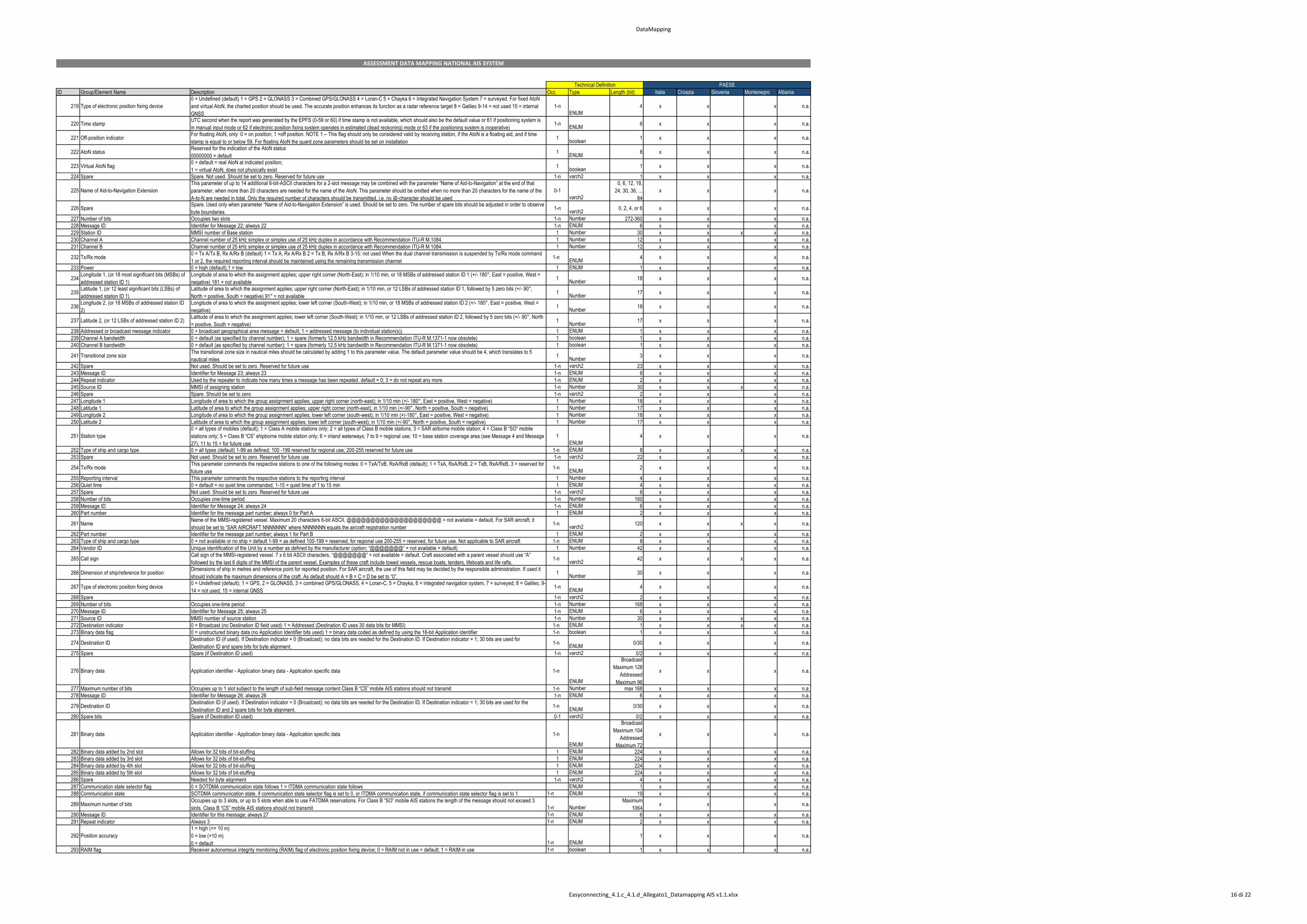
DataMapping
ID Group/Element Name Description Occ. Type Length (bit) Italia Croazia Slovenia Montenegro Albania
Technical Definition PAESE
ASSESSMENT DATA MAPPING NATIONAL AIS SYSTEM
219 Type of electronic position fixing device
0 = Undefined (default) 1 = GPS 2 = GLONASS 3 = Combined GPS/GLONASS 4 = Loran-C 5 = Chayka 6 = Integrated Navigation System 7 = surveyed. For fixed AtoN
and virtual AtoN, the charted position should be used. The accurate position enhances its function as a radar reference target 8 = Galileo 9-14 = not used 15 = internal
GNSS
1-n
ENUM
4 x x x n.a.
220 Time stamp UTC second when the report was generated by the EPFS (0-59 or 60) if time stamp is not available, which should also be the default value or 61 if positioning system is
in manual input mode or 62 if electronic position fixing system operates in estimated (dead reckoning) mode or 63 if the positioning system is inoperative) 1-n
ENUM6 x x x n.a.
221 Off-position indicator For floating AtoN, only: 0 = on position; 1 =off position. NOTE 1 – This flag should only be considered valid by receiving station, if the AtoN is a floating aid, and if time
stamp is equal to or below 59. For floating AtoN the guard zone parameters should be set on installation 1
boolean1 x x x n.a.
222 AtoN status Reserved for the indication of the AtoN status
00000000 = default 1
ENUM8 x x x n.a.
223 Virtual AtoN flag 0 = default = real AtoN at indicated position;
1 = virtual AtoN, does not physically exist 1
boolean1 x x x n.a.
224 Spare Spare. Not used. Should be set to zero. Reserved for future use 1-n varch2 1 x x x n.a.
225 Name of Aid-to-Navigation Extension
This parameter of up to 14 additional 6-bit-ASCII characters for a 2-slot message may be combined with the parameter “Name of Aid-to-Navigation” at the end of that
parameter, when more than 20 characters are needed for the name of the AtoN. This parameter should be omitted when no more than 20 characters for the name of the
A-to-N are needed in total. Only the required number of characters should be transmitted, i.e. no @-character should be used
0-1
varch2
0, 6, 12, 18,
24, 30, 36, ...
84
x x x n.a.
226 Spare Spare. Used only when parameter “Name of Aid-to-Navigation Extension” is used. Should be set to zero. The number of spare bits should be adjusted in order to observe
byte boundaries 1-n
varch20, 2, 4, or 6 x x x n.a.
227 Number of bits Occupies two slots 1-n Number 272-360 x x x n.a.
228 Message ID Identifier for Message 22; always 22 1-n ENUM 6 x x x n.a.
229 Station ID MMSI number of Base station 1 Number 30 x x x x n.a.
230 Channel A Channel number of 25 kHz simplex or simplex use of 25 kHz duplex in accordance with Recommendation ITU-R M.1084. 1 Number 12 x x x n.a.
231 Channel B Channel number of 25 kHz simplex or simplex use of 25 kHz duplex in accordance with Recommendation ITU-R M.1084. 1 Number 12 x x x n.a.
232 Tx/Rx mode 0 = Tx A/Tx B, Rx A/Rx B (default) 1 = Tx A, Rx A/Rx B 2 = Tx B, Rx A/Rx B 3-15: not used When the dual channel transmission is suspended by Tx/Rx mode command
1 or 2, the required reporting interval should be maintained using the remaining transmission channel 1-n
ENUM4 x x x n.a.
233 Power 0 = high (default),1 = low 1 ENUM 1 x x x n.a.
234Longitude 1, (or 18 most significant bits (MSBs) of
addressed station ID 1)
Longitude of area to which the assignment applies; upper right corner (North-East); in 1/10 min, or 18 MSBs of addressed station ID 1 (+/- 180°, East = positive, West =
negative) 181 = not available1
Number18 x x x n.a.
235Latitude 1, (or 12 least significant bits (LSBs) of
addressed station ID 1)
Latitude of area to which the assignment applies; upper right corner (North-East); in 1/10 min, or 12 LSBs of addressed station ID 1, followed by 5 zero bits (+/- 90°,
North = positive, South = negative) 91° = not available1
Number17 x x x n.a.
236Longitude 2, (or 18 MSBs of addressed station ID
2)
Longitude of area to which the assignment applies; lower left corner (South-West); in 1/10 min, or 18 MSBs of addressed station ID 2 (+/- 180°, East = positive, West =
negative)1
Number18 x x x n.a.
237 Latitude 2, (or 12 LSBs of addressed station ID 2)Latitude of area to which the assignment applies; lower left corner (South-West); in 1/10 min, or 12 LSBs of addressed station ID 2, followed by 5 zero bits (+/- 90°, North
= positive, South = negative)1
Number17 x x x n.a.
238 Addressed or broadcast message indicator 0 = broadcast geographical area message = default; 1 = addressed message (to individual station(s)) 1 ENUM 1 x x x n.a.
239 Channel A bandwidth 0 = default (as specified by channel number); 1 = spare (formerly 12.5 kHz bandwidth in Recommendation ITU-R M.1371-1 now obsolete) 1 boolean 1 x x x n.a.
240 Channel B bandwidth 0 = default (as specified by channel number); 1 = spare (formerly 12.5 kHz bandwidth in Recommendation ITU-R M.1371-1 now obsolete) 1 boolean 1 x x x n.a.
241 Transitional zone size The transitional zone size in nautical miles should be calculated by adding 1 to this parameter value. The default parameter value should be 4, which translates to 5
nautical miles1
Number3 x x x n.a.
242 Spare Not used. Should be set to zero. Reserved for future use 1-n varch2 23 x x x n.a.
243 Message ID Identifier for Message 23; always 23 1-n ENUM 6 x x x n.a.
244 Repeat indicator Used by the repeater to indicate how many times a message has been repeated. default = 0; 3 = do not repeat any more 1-n ENUM 2 x x x n.a.
245 Source ID MMSI of assigning station 1-n Number 30 x x x x n.a.
246 Spare Spare. Should be set to zero 1-n varch2 2 x x x n.a.
247 Longitude 1 Longitude of area to which the group assignment applies; upper right corner (north-east); in 1/10 min (+/- 180°, East = positive, West = negative) 1 Number 18 x x x n.a.
248 Latitude 1 Latitude of area to which the group assignment applies; upper right corner (north-east); in 1/10 min (+/-90°, North = positive, South = negative) 1 Number 17 x x x n.a.
249 Longitude 2 Longitude of area to which the group assignment applies; lower left corner (south-west); in 1/10 min (+/-180°, East = positive, West = negative) 1 Number 18 x x x n.a.
250 Latitude 2 Latitude of area to which the group assignment applies; lower left corner (south-west); in 1/10 min (+/-90°, North = positive, South = negative) 1 Number 17 x x x n.a.
251 Station type
0 = all types of mobiles (default); 1 = Class A mobile stations only; 2 = all types of Class B mobile stations; 3 = SAR airborne mobile station; 4 = Class B “SO” mobile
stations only; 5 = Class B “CS” shipborne mobile station only; 6 = inland waterways; 7 to 9 = regional use; 10 = base station coverage area (see Message 4 and Message
27); 11 to 15 = for future use
1
ENUM
4 x x x n.a.
252 Type of ship and cargo type 0 = all types (default) 1-99 as defined; 100 -199 reserved for regional use; 200-255 reserved for future use 1-n ENUM 8 x x x x n.a.
253 Spare Not used. Should be set to zero. Reserved for future use 1-n varch2 22 x x x n.a.
254 Tx/Rx mode This parameter commands the respective stations to one of the following modes: 0 = TxA/TxB, RxA/RxB (default); 1 = TxA, RxA/RxB, 2 = TxB, RxA/RxB, 3 = reserved for
future use 1-n
ENUM2 x x x n.a.
255 Reporting interval This parameter commands the respective stations to the reporting interval 1 Number 4 x x x n.a.
256 Quiet time 0 = default = no quiet time commanded; 1-15 = quiet time of 1 to 15 min 1 ENUM 4 x x x n.a.
257 Spare Not used. Should be set to zero. Reserved for future use 1-n varch2 6 x x x n.a.
258 Number of bits Occupies one-time period 1-n Number 160 x x x n.a.
259 Message ID Identifier for Message 24; always 24 1-n ENUM 6 x x x n.a.
260 Part number Identifier for the message part number; always 0 for Part A 1 ENUM 2 x x x n.a.
261 Name Name of the MMSI-registered vessel. Maximum 20 characters 6-bit ASCII, @@@@@@@@@@@@@@@@@@@@ = not available = default. For SAR aircraft, it
should be set to “SAR AIRCRAFT NNNNNNN” where NNNNNNN equals the aircraft registration number 1-n
varch2120 x x x x n.a.
262 Part number Identifier for the message part number; always 1 for Part B 1 ENUM 2 x x x n.a.
263 Type of ship and cargo type 0 = not available or no ship = default 1-99 = as defined 100-199 = reserved, for regional use 200-255 = reserved, for future use. Not applicable to SAR aircraft 1-n ENUM 8 x x x n.a.
264 Vendor ID Unique identification of the Unit by a number as defined by the manufacturer (option; “@@@@@@@” = not available = default) 1 Number 42 x x x n.a.
265 Call sign Call sign of the MMSI-registered vessel. 7 x 6 bit ASCII characters, “@@@@@@@” = not available = default. Craft associated with a parent vessel should use “A”
followed by the last 6 digits of the MMSI of the parent vessel. Examples of these craft include towed vessels, rescue boats, tenders, lifeboats and life rafts. 1-n
varch242 x x x x n.a.
266 Dimension of ship/reference for position Dimensions of ship in metres and reference point for reported position. For SAR aircraft, the use of this field may be decided by the responsible administration. If used it
should indicate the maximum dimensions of the craft. As default should A = B = C = D be set to “0”. 1
Number30 x x x n.a.
267 Type of electronic position fixing device 0 = Undefined (default); 1 = GPS, 2 = GLONASS, 3 = combined GPS/GLONASS, 4 = Loran-C, 5 = Chayka, 6 = integrated navigation system, 7 = surveyed; 8 = Galileo, 9-
14 = not used, 15 = internal GNSS 1-n
ENUM4 x x x n.a.
268 Spare 1-n varch2 2 x x x n.a.
269 Number of bits Occupies one-time period 1-n Number 168 x x x n.a.
270 Message ID Identifier for Message 25; always 25 1-n ENUM 6 x x x n.a.
271 Source ID MMSI number of source station 1-n Number 30 x x x x n.a.
272 Destination indicator 0 = Broadcast (no Destination ID field used) 1 = Addressed (Destination ID uses 30 data bits for MMSI) 1-n ENUM 1 x x x x n.a.
273 Binary data flag 0 = unstructured binary data (no Application Identifier bits used) 1 = binary data coded as defined by using the 16-bit Application identifier 1-n boolean 1 x x x n.a.
274 Destination IDDestination ID (if used). If Destination indicator = 0 (Broadcast); no data bits are needed for the Destination ID. If Destination indicator = 1; 30 bits are used for
Destination ID and spare bits for byte alignment.1-n
ENUM0/30 x x x n.a.
275 Spare Spare (if Destination ID used) 1-n varch2 0/2 x x x n.a.
276 Binary data Application identifier - Application binary data - Application specific data 1-n
ENUM
Broadcast
Maximum 128
Addressed
Maximum 96
x x x n.a.
277 Maximum number of bits Occupies up to 1 slot subject to the length of sub-field message content Class B “CS” mobile AIS stations should not transmit 1-n Number max 168 x x x n.a.
278 Message ID Identifier for Message 26; always 26 1-n ENUM 6 x x x n.a.
279 Destination IDDestination ID (if used). If Destination indicator = 0 (Broadcast); no data bits are needed for the Destination ID. If Destination indicator = 1; 30 bits are used for the
Destination ID and 2 spare bits for byte alignment.1-n
ENUM0/30 x x x n.a.
280 Spare bits Spare (if Destination ID used) 0-1 varch2 0/2 x x x n.a.
281 Binary data Application identifier - Application binary data - Application specific data 1-n
ENUM
Broadcast
Maximum 104
Addressed
Maximum 72
x x x n.a.
282 Binary data added by 2nd slot Allows for 32 bits of bit-stuffing 1 ENUM 224 x x x n.a.
283 Binary data added by 3rd slot Allows for 32 bits of bit-stuffing 1 ENUM 224 x x x n.a.
284 Binary data added by 4th slot Allows for 32 bits of bit-stuffing 1 ENUM 224 x x x n.a.
285 Binary data added by 5th slot Allows for 32 bits of bit-stuffing 1 ENUM 224 x x x n.a.
286 Spare Needed for byte alignment 1-n varch2 4 x x x n.a.
287 Communication state selector flag 0 = SOTDMA communication state follows 1 = ITDMA communication state follows ENUM 1 x x x n.a.
288 Communication state SOTDMA communication state, if communication state selector flag is set to 0, or ITDMA communication state, if communication state selector flag is set to 1 1-n ENUM 19 x x x n.a.
289 Maximum number of bits Occupies up to 3 slots, or up to 5 slots when able to use FATDMA reservations. For Class B “SO” mobile AIS stations the length of the message should not exceed 3
slots. Class B “CS” mobile AIS stations should not transmit 1-n Number
Maximum
1064 x x x n.a.
290 Message ID Identifier for this message; always 27 1-n ENUM 6 x x x n.a.
291 Repeat indicator Always 3 1-n ENUM 2 x x x n.a.
292 Position accuracy
1 = high (<= 10 m)
0 = low (>10 m)
0 = default 1-n ENUM
1 x x x n.a.
293 RAIM flag Receiver autonomous integrity monitoring (RAIM) flag of electronic position fixing device; 0 = RAIM not in use = default; 1 = RAIM in use 1-n boolean 1 x x x n.a.
Easyconnecting_4.1.c_4.1.d_Allegato1_Datamapping AIS v1.1.xlsx 16 di 22
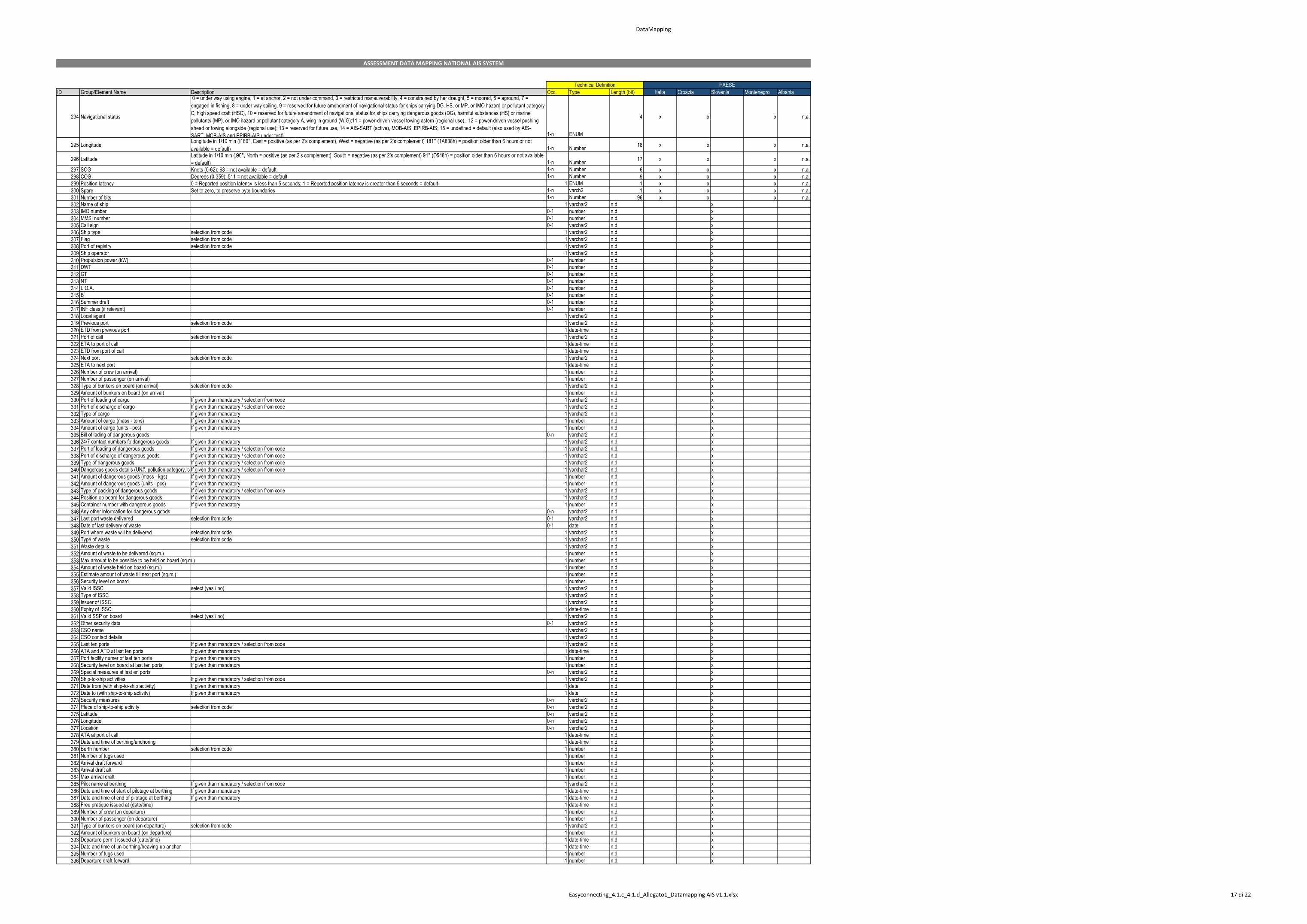
DataMapping
ID Group/Element Name Description Occ. Type Length (bit) Italia Croazia Slovenia Montenegro Albania
Technical Definition PAESE
ASSESSMENT DATA MAPPING NATIONAL AIS SYSTEM
294 Navigational status
0 = under way using engine, 1 = at anchor, 2 = not under command, 3 = restricted maneuverability, 4 = constrained by her draught, 5 = moored, 6 = aground, 7 =
engaged in fishing, 8 = under way sailing, 9 = reserved for future amendment of navigational status for ships carrying DG, HS, or MP, or IMO hazard or pollutant category
C, high speed craft (HSC), 10 = reserved for future amendment of navigational status for ships carrying dangerous goods (DG), harmful substances (HS) or marine
pollutants (MP), or IMO hazard or pollutant category A, wing in ground (WIG);11 = power-driven vessel towing astern (regional use), 12 = power-driven vessel pushing
ahead or towing alongside (regional use); 13 = reserved for future use, 14 = AIS-SART (active), MOB-AIS, EPIRB-AIS; 15 = undefined = default (also used by AIS-
SART, MOB-AIS and EPIRB-AIS under test) 1-n ENUM
4 x x x n.a.
295 Longitude available = default) 1-n Number
18 x x x n.a.
296 Latitude = default) 1-n Number
17 x x x n.a.
297 SOG Knots (0-62); 63 = not available = default 1-n Number 6 x x x n.a.
298 COG Degrees (0-359); 511 = not available = default 1-n Number 9 x x x n.a.
299 Position latency 0 = Reported position latency is less than 5 seconds; 1 = Reported position latency is greater than 5 seconds = default 1 ENUM 1 x x x n.a.
300 Spare Set to zero, to preserve byte boundaries 1-n varch2 1 x x x n.a.
301 Number of bits 1-n Number 96 x x x n.a.
302 Name of ship 1 varchar2 n.d. x
303 IMO number 0-1 number n.d. x
304 MMSI number 0-1 number n.d. x
305 Call sign 0-1 varchar2 n.d. x
306 Ship type selection from code 1 varchar2 n.d. x
307 Flag selection from code 1 varchar2 n.d. x
308 Port of registry selection from code 1 varchar2 n.d. x
309 Ship operator 1 varchar2 n.d. x
310 Propulsion power (kW) 0-1 number n.d. x
311 DWT 0-1 number n.d. x
312 GT 0-1 number n.d. x
313 NT 0-1 number n.d. x
314 L.O.A. 0-1 number n.d. x
315 B 0-1 number n.d. x
316 Summer draft 0-1 number n.d. x
317 INF class (if relevant) 0-1 number n.d. x
318 Local agent 1 varchar2 n.d. x
319 Previous port selection from code 1 varchar2 n.d. x
320 ETD from previous port 1 date-time n.d. x
321 Port of call selection from code 1 varchar2 n.d. x
322 ETA to port of call 1 date-time n.d. x
323 ETD from port of call 1 date-time n.d. x
324 Next port selection from code 1 varchar2 n.d. x
325 ETA to next port 1 date-time n.d. x
326 Number of crew (on arrival) 1 number n.d. x
327 Number of passenger (on arrival) 1 number n.d. x
328 Type of bunkers on board (on arrival) selection from code 1 varchar2 n.d. x
329 Amount of bunkers on board (on arrival) 1 number n.d. x
330 Port of loading of cargo If given than mandatory / selection from code 1 varchar2 n.d. x
331 Port of discharge of cargo If given than mandatory / selection from code 1 varchar2 n.d. x
332 Type of cargo If given than mandatory 1 varchar2 n.d. x
333 Amount of cargo (mass - tons) If given than mandatory 1 number n.d. x
334 Amount of cargo (units - pcs) If given than mandatory 1 number n.d. x
335 Bill of lading of dangerous goods 0-n varchar2 n.d. x
336 24/7 contact numbers fo dangerous goods If given than mandatory 1 varchar2 n.d. x
337 Port of loading of dangerous goods If given than mandatory / selection from code 1 varchar2 n.d. x
338 Port of discharge of dangerous goods If given than mandatory / selection from code 1 varchar2 n.d. x
339 Type of dangerous goods If given than mandatory / selection from code 1 varchar2 n.d. x
340 Dangerous goods details (UN#, pollution category, class, hazards) according to IMDG, IBC, IGC, IMSBC or MARPOLIf given than mandatory / selection from code 1 varchar2 n.d. x
341 Amount of dangerous goods (mass - kgs) If given than mandatory 1 number n.d. x
342 Amount of dangerous goods (units - pcs) If given than mandatory 1 number n.d. x
343 Type of packing of dangerous goods If given than mandatory / selection from code 1 varchar2 n.d. x
344 Position ob board for dangerous goods If given than mandatory 1 varchar2 n.d. x
345 Container number with dangerous goods If given than mandatory 1 number n.d. x
346 Any other information for dangerous goods 0-n varchar2 n.d. x
347 Last port waste delivered selection from code 0-1 varchar2 n.d. x
348 Date of last delivery of waste 0-1 date n.d. x
349 Port where waste will be delivered selection from code 1 varchar2 n.d. x
350 Type of waste selection from code 1 varchar2 n.d. x
351 Waste details 1 varchar2 n.d. x
352 Amount of waste to be delivered (sq.m.) 1 number n.d. x
353 Max amount to be possible to be held on board (sq.m.) 1 number n.d. x
354 Amount of waste held on board (sq.m.) 1 number n.d. x
355 Estimate amount of waste till next port (sq.m.) 1 number n.d. x
356 Security level on board 1 number n.d. x
357 Valid ISSC select (yes / no) 1 varchar2 n.d. x
358 Type of ISSC 1 varchar2 n.d. x
359 Issuer of ISSC 1 varchar2 n.d. x
360 Expiry of ISSC 1 date-time n.d. x
361 Valid SSP on board select (yes / no) 1 varchar2 n.d. x
362 Other security data 0-1 varchar2 n.d. x
363 CSO name 1 varchar2 n.d. x
364 CSO contact details 1 varchar2 n.d. x
365 Last ten ports If given than mandatory / selection from code 1 varchar2 n.d. x
366 ATA and ATD at last ten ports If given than mandatory 1 date-time n.d. x
367 Port facility numer of last ten ports If given than mandatory 1 number n.d. x
368 Security level on board at last ten ports If given than mandatory 1 number n.d. x
369 Special measures at last en ports 0-n varchar2 n.d. x
370 Ship-to-ship activities If given than mandatory / selection from code 1 varchar2 n.d. x
371 Date from (with ship-to-ship activity) If given than mandatory 1 date n.d. x
372 Date to (with ship-to-ship activity) If given than mandatory 1 date n.d. x
373 Security measures 0-n varchar2 n.d. x
374 Place of ship-to-ship activity selection from code 0-n varchar2 n.d. x
375 Latitude 0-n varchar2 n.d. x
376 Longitude 0-n varchar2 n.d. x
377 Location 0-n varchar2 n.d. x
378 ATA at port of call 1 date-time n.d. x
379 Date and time of berthing/anchoring 1 date-time n.d. x
380 Berth number selection from code 1 number n.d. x
381 Number of tugs used 1 number n.d. x
382 Arrival draft forward 1 number n.d. x
383 Arrival draft aft 1 number n.d. x
384 Max arrival draft 1 number n.d. x
385 Pilot name at berthing If given than mandatory / selection from code 1 varchar2 n.d. x
386 Date and time of start of pilotage at berthing If given than mandatory 1 date-time n.d. x
387 Date and time of end of pilotage at berthing If given than mandatory 1 date-time n.d. x
388 Free pratique issued at (date/time) 1 date-time n.d. x
389 Number of crew (on departure) 1 number n.d. x
390 Number of passenger (on departure) 1 number n.d. x
391 Type of bunkers on board (on departure) selection from code 1 varchar2 n.d. x
392 Amount of bunkers on board (on departure) 1 number n.d. x
393 Departure permit issued at (date/time) 1 date-time n.d. x
394 Date and time of un-berthing/heaving-up anchor 1 date-time n.d. x
395 Number of tugs used 1 number n.d. x
396 Departure draft forward 1 number n.d. x
Easyconnecting_4.1.c_4.1.d_Allegato1_Datamapping AIS v1.1.xlsx 17 di 22
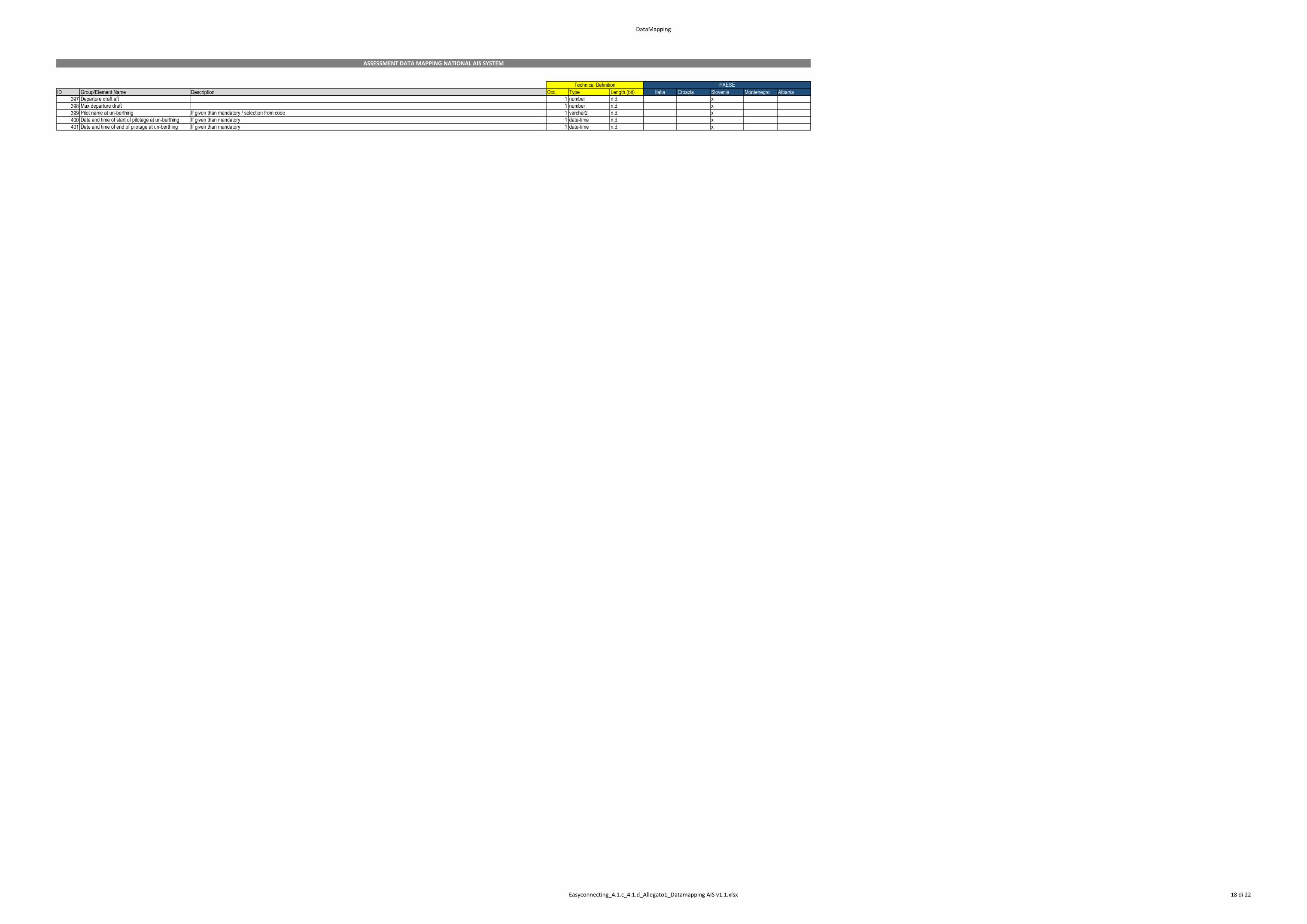
DataMapping
ID Group/Element Name Description Occ. Type Length (bit) Italia Croazia Slovenia Montenegro Albania
Technical Definition PAESE
ASSESSMENT DATA MAPPING NATIONAL AIS SYSTEM
397 Departure draft aft 1 number n.d. x
398 Max departure draft 1 number n.d. x
399 Pilot name at un-berthing If given than mandatory / selection from code 1 varchar2 n.d. x
400 Date and time of start of pilotage at un-berthing If given than mandatory 1 date-time n.d. x
401 Date and time of end of pilotage at un-berthing If given than mandatory 1 date-time n.d. x
Easyconnecting_4.1.c_4.1.d_Allegato1_Datamapping AIS v1.1.xlsx 18 di 22
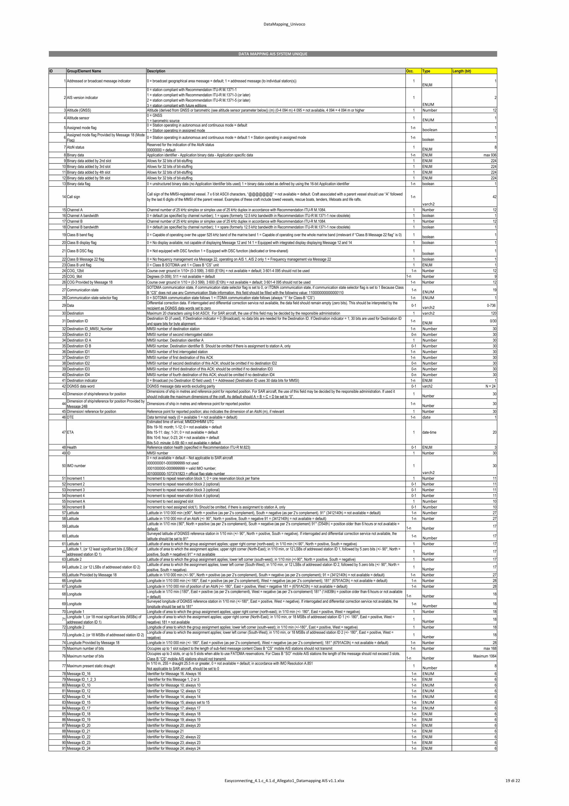
DataMapping_Univoco
ID Group/Element Name Description Occ. Type Length (bit)
1 Addressed or broadcast message indicator 0 = broadcast geographical area message = default; 1 = addressed message (to individual station(s)) 1ENUM
1
2 AIS version indicator
0 = station compliant with Recommendation ITU-R M.1371-1
1 = station compliant with Recommendation ITU-R M.1371-3 (or later)
2 = station compliant with Recommendation ITU-R M.1371-5 (or later)
3 = station compliant with future editions
1
ENUM
2
3 Altitude (GNSS) Altitude (derived from GNSS or barometric (see altitude sensor parameter below)) (m) (0-4 094 m) 4 095 = not available, 4 094 = 4 094 m or higher 1 Number 12
4 Altitude sensor0 = GNSS
1 = barometric source 1 ENUM 1
5 Assigned mode flag 0 = Station operating in autonomous and continuous mode = default
1 = Station operating in assigned mode 1-n boolean 1
6Assigned mode flag Provided by Message 18 (Mode
Flag) 0 = Station operating in autonomous and continuous mode = default 1 = Station operating in assigned mode 1-n
boolean1
7 AtoN status Reserved for the indication of the AtoN status
00000000 = default 1
ENUM8
8 Binary data Application identifier - Application binary data - Application specific data 1-n ENUM max 936
9 Binary data added by 2nd slot Allows for 32 bits of bit-stuffing 1 ENUM 224
10 Binary data added by 3rd slot Allows for 32 bits of bit-stuffing 1 ENUM 224
11 Binary data added by 4th slot Allows for 32 bits of bit-stuffing 1 ENUM 224
12 Binary data added by 5th slot Allows for 32 bits of bit-stuffing 1 ENUM 224
13 Binary data flag 0 = unstructured binary data (no Application Identifier bits used) 1 = binary data coded as defined by using the 16-bit Application identifier 1-n boolean 1
14 Call sign Call sign of the MMSI-registered vessel. 7 x 6 bit ASCII characters, “@@@@@@@” = not available = default. Craft associated with a parent vessel should use “A” followed
by the last 6 digits of the MMSI of the parent vessel. Examples of these craft include towed vessels, rescue boats, tenders, lifeboats and life rafts. 1-n
varch2
42
15 Channel A Channel number of 25 kHz simplex or simplex use of 25 kHz duplex in accordance with Recommendation ITU-R M.1084. 1 Number 12
16 Channel A bandwidth 0 = default (as specified by channel number); 1 = spare (formerly 12.5 kHz bandwidth in Recommendation ITU-R M.1371-1 now obsolete) 1 boolean 1
17 Channel B Channel number of 25 kHz simplex or simplex use of 25 kHz duplex in accordance with Recommendation ITU-R M.1084. 1 Number 12
18 Channel B bandwidth 0 = default (as specified by channel number); 1 = spare (formerly 12.5 kHz bandwidth in Recommendation ITU-R M.1371-1 now obsolete) 1 boolean 1
19 Class B band flag 0 = Capable of operating over the upper 525 kHz band of the marine band 1 = Capable of operating over the whole marine band (irrelevant if “Class B Message 22 flag” is 0) 1boolean
1
20 Class B display flag 0 = No display available; not capable of displaying Message 12 and 14 1 = Equipped with integrated display displaying Message 12 and 14 1 boolean 1
21 Class B DSC flag 0 = Not equipped with DSC function 1 = Equipped with DSC function (dedicated or time-shared) 1boolean
1
22 Class B Message 22 flag 0 = No frequency management via Message 22, operating on AIS 1, AIS 2 only 1 = Frequency management via Message 22 1 boolean 1
23 Class B unit flag 0 = Class B SOTDMA unit 1 = Class B “CS” unit 1 ENUM 1
24 COG_12bit Course over ground in 1/10= (0-3 599). 3 600 (E10h) = not available = default; 3 601-4 095 should not be used 1-n Number 12
25 COG_9bit Degrees (0-359); 511 = not available = default 1-n Number 9
26 COG Provided by Message 18 Course over ground in 1/10 = (0-3 599). 3 600 (E10h) = not available = default; 3 601-4 095 should not be used 1-n Number 12
27 Communication state SOTDMA communication state, if communication state selector flag is set to 0, or ITDMA communication state, if communication state selector flag is set to 1 Because Class
B “CS” does not use any Communication State information, this field should be filled with the following value: 1100000000000000110 1-n ENUM 19
28 Communication state selector flag 0 = SOTDMA communication state follows 1 = ITDMA communication state follows (always “1” for Class-B “CS”) 1-n ENUM 1
29 Data Differential correction data. If interrogated and differential correction service not available, the data field should remain empty (zero bits). This should be interpreted by the
recipient as DGNSS data words set to zero 0-1 varch2 0-736
30 Destination Maximum 20 characters using 6-bit ASCII; For SAR aircraft, the use of this field may be decided by the responsible administration 1 varch2 120
31 Destination IDDestination ID (if used). If Destination indicator = 0 (Broadcast); no data bits are needed for the Destination ID. If Destination indicator = 1; 30 bits are used for Destination ID
and spare bits for byte alignment.1-n
ENUM0/30
32 Destination ID_MMSI_Number MMSI number of destination station 1-n Number 30
33 Destination ID 2 MMSI number of second interrogated station 0-n Number 30
34 Destination ID A MMSI number. Destination identifier A 1 Number 30
35 Destination ID B MMSI number. Destination identifier B. Should be omitted if there is assignment to station A, only 0-1 Number 30
36 Destination ID1 MMSI number of first interrogated station 1-n Number 30
37 Destination ID1 MMSI number of first destination of this ACK 1-n Number 30
38 Destination ID2 MMSI number of second destination of this ACK; should be omitted if no destination ID2 0-n Number 30
39 Destination ID3 MMSI number of third destination of this ACK; should be omitted if no destination ID3 0-n Number 30
40 Destination ID4 MMSI number of fourth destination of this ACK; should be omitted if no destination ID4 0-n Number 30
41 Destination indicator 0 = Broadcast (no Destination ID field used) 1 = Addressed (Destination ID uses 30 data bits for MMSI) 1-n ENUM 1
42 DGNSS data word DGNSS message data words excluding parity 0-1 varch2 N = 24
43 Dimension of ship/reference for position Dimensions of ship in metres and reference point for reported position. For SAR aircraft, the use of this field may be decided by the responsible administration. If used it
should indicate the maximum dimensions of the craft. As default should A = B = C = D be set to “0”. 1
Number30
44Dimension of ship/reference for position Provided by
Message 24B Dimensions of ship in metres and reference point for reported position 1-n
Number30
45 Dimension/ reference for position Reference point for reported position; also indicates the dimension of an AtoN (m), if relevant 1 Number 30
46 DTE Data terminal ready (0 = available 1 = not available = default) 1-n date 1
47 ETA
Estimated time of arrival; MMDDHHMM UTC
Bits 19-16: month; 1-12; 0 = not available = default
Bits 15-11: day; 1-31; 0 = not available = default
Bits 10-6: hour; 0-23; 24 = not available = default
Bits 5-0: minute; 0-59; 60 = not available = default
1 date-time 20
48 Health Reference station health (specified in Recommendation ITU-R M.823) 0-1 ENUM 3
49 ID MMSI number 1 Number 30
50 IMO number
0 = not available = default – Not applicable to SAR aircraft
0000000001-0000999999 not used
0001000000-0009999999 = valid IMO number;
0010000000-1073741823 = official flag state number
1
varch2
30
51 Increment 1 Increment to repeat reservation block 1; 0 = one reservation block per frame 1 Number 11
52 Increment 2 Increment to repeat reservation block 2 (optional) 0-1 Number 11
53 Increment 3 Increment to repeat reservation block 3 (optional) 0-1 Number 11
54 Increment 4 Increment to repeat reservation block 4 (optional) 0-1 Number 11
55 Increment A Increment to next assigned slot 1 Number 10
56 Increment B Increment to next assigned slot(1). Should be omitted, if there is assignment to station A, only 0-1 Number 10
57 Latitude Latitude in 1/10 000 min (±90°, North = positive (as per 2’s complement), South = negative (as per 2’s complement). 91° (3412140h) = not available = default) 1-n Number 27
58 Latitude Latitude in 1/10 000 min of an AtoN (+/- 90°, North = positive, South = negative 91 = (3412140h) = not available = default) 1-n Number 27
59 Latitude default) 1-n Number
17
60 Latitude Surveyed latitude of DGNSS reference station in 1/10 min (+/- 90°, North = positive, South = negative). If interrogated and differential correction service not available, the
latitude should be set to 91° 1-n Number 17
61 Latitude 1 Latitude of area to which the group assignment applies; upper right corner (north-east); in 1/10 min (+/-90°, North = positive, South = negative) 1 Number 17
62Latitude 1, (or 12 least significant bits (LSBs) of
addressed station ID 1)
Latitude of area to which the assignment applies; upper right corner (North-East); in 1/10 min, or 12 LSBs of addressed station ID 1, followed by 5 zero bits (+/- 90°, North =
positive, South = negative) 91° = not available1
Number17
63 Latitude 2 Latitude of area to which the group assignment applies; lower left corner (south-west); in 1/10 min (+/-90°, North = positive, South = negative) 1 Number 17
64 Latitude 2, (or 12 LSBs of addressed station ID 2)Latitude of area to which the assignment applies; lower left corner (South-West); in 1/10 min, or 12 LSBs of addressed station ID 2, followed by 5 zero bits (+/- 90°, North =
positive, South = negative)1
Number17
65 Latitude Provided by Message 18 Latitude in 1/10 000 min (+/- 90°, North = positive (as per 2’s complement), South = negative (as per 2’s complement); 91 = (3412140h) = not available = default) 1-n Number 27
66 Longitude Longitude in 1/10 000 min (+/-180°, East = positive (as per 2’s complement), West = negative (as per 2’s complement); 181° (6791AC0h) = not available = default) 1-n Number 28
67 Longitude Longitude in 1/10 000 min of position of an AtoN (+/- 180°, East = positive, West = negative 181 = (6791AC0h) = not available = default) 1-n Number 28
68 Longitude = default) 1-n Number
18
69 Longitude Surveyed longitude of DGNSS reference station in 1/10 min (+/-180°, East = positive, West = negative). If interrogated and differential correction service not available, the
longitude should be set to 181° 1-n Number 18
70 Longitude 1 Longitude of area to which the group assignment applies; upper right corner (north-east); in 1/10 min (+/- 180°, East = positive, West = negative) 1 Number 18
71Longitude 1, (or 18 most significant bits (MSBs) of
addressed station ID 1)
Longitude of area to which the assignment applies; upper right corner (North-East); in 1/10 min, or 18 MSBs of addressed station ID 1 (+/- 180°, East = positive, West =
negative) 181 = not available1
Number18
72 Longitude 2 Longitude of area to which the group assignment applies; lower left corner (south-west); in 1/10 min (+/-180°, East = positive, West = negative) 1 Number 18
73 Longitude 2, (or 18 MSBs of addressed station ID 2)Longitude of area to which the assignment applies; lower left corner (South-West); in 1/10 min, or 18 MSBs of addressed station ID 2 (+/- 180°, East = positive, West =
negative)1
Number18
74 Longitude Provided by Message 18 Longitude in 1/10 000 min (+/- 180°, East = positive (as per 2’s complement), West = negative (as per 2’s complement); 181° (6791AC0h) = not available = default) 1-n Number 28
75 Maximum number of bits Occupies up to 1 slot subject to the length of sub-field message content Class B “CS” mobile AIS stations should not transmit 1-n Number max 168
76 Maximum number of bits Occupies up to 3 slots, or up to 5 slots when able to use FATDMA reservations. For Class B “SO” mobile AIS stations the length of the message should not exceed 3 slots.
Class B “CS” mobile AIS stations should not transmit 1-n NumberMaximum 1064
77 Maximum present static draught In 1/10 m, 255 = draught 25.5 m or greater, 0 = not available = default; in accordance with IMO Resolution A.851
Not applicable to SAR aircraft, should be set to 0 1 Number 8
78 Message ID_16 Identifier for Message 16. Always 16 1-n ENUM 6
79 Message ID_1_2_3 Identifier for this Message 1, 2 or 3 1-n ENUM 6
80 Message ID_10 Identifier for Message 10; always 10 1-n ENUM 6
81 Message ID_12 Identifier for Message 12; always 12 1-n ENUM 6
82 Message ID_14 Identifier for Message 14; always 14 1-n ENUM 6
83 Message ID_15 Identifier for Message 15; always set to 15 1-n ENUM 6
84 Message ID_17 Identifier for Message 17; always 17 1-n ENUM 6
85 Message ID_18 Identifier for Message 18; always 18 1-n ENUM 6
86 Message ID_19 Identifier for Message 19; always 19 1-n ENUM 6
87 Message ID_20 Identifier for Message 20; always 20 1-n ENUM 6
88 Message ID_21 Identifier for Message 21 1-n ENUM 6
89 Message ID_22 Identifier for Message 22; always 22 1-n ENUM 6
90 Message ID_23 Identifier for Message 23; always 23 1-n ENUM 6
91 Message ID_24 Identifier for Message 24; always 24 1-n ENUM 6
DATA MAPPING AIS SYSTEM UNIQUE
Easyconnecting_4.1.c_4.1.d_Allegato1_Datamapping AIS v1.1.xlsx 19 di 22
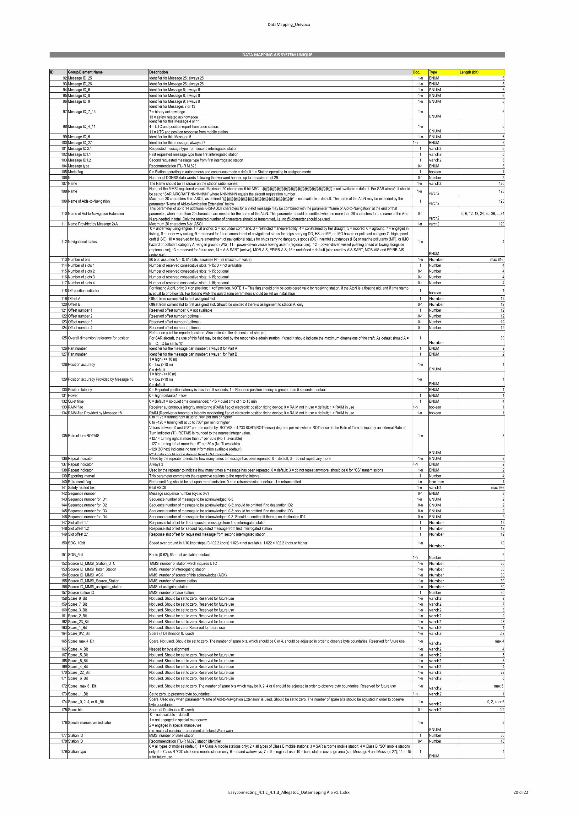
DataMapping_Univoco
ID Group/Element Name Description Occ. Type Length (bit)
DATA MAPPING AIS SYSTEM UNIQUE
92 Message ID_25 Identifier for Message 25; always 25 1-n ENUM 6
93 Message ID_26 Identifier for Message 26; always 26 1-n ENUM 6
94 Message ID_6 Identifier for Message 6; always 6 1-n ENUM 6
95 Message ID_8 Identifier for Message 8; always 8 1-n ENUM 6
96 Message ID_9 Identifier for Message 9; always 9 1-n ENUM 6
97 Message ID_7_13
Identifier for Messages 7 or 13
7 = binary acknowledge
13 = safety related acknowledge
1-n ENUM
6
98 Message ID_4_11
Identifier for this Message 4 or 11
4 = UTC and position report from base station:
11 = UTC and position response from mobile station
1-n ENUM
6
99 Message ID_5 Identifier for this Message 5 1-n ENUM 6
100 Message ID_27 Identifier for this message; always 27 1-n ENUM 6
101 Message ID 2.1 Requested message type from second interrogated station 1 varch2 6
102 Message ID1.1 First requested message type from first interrogated station 1 varch2 6
103 Message ID1.2 Second requested message type from first interrogated station 1 varch2 6
104 Message type Recommendation ITU-R M.823 0-1 ENUM 6
105 Mode flag 0 = Station operating in autonomous and continuous mode = default 1 = Station operating in assigned mode 1 boolean 1
106 N Number of DGNSS data words following the two word header, up to a maximum of 29 0-1 Number 5
107 Name The Name should be as shown on the station radio license. 1-n varch2 120
108 Name Name of the MMSI-registered vessel. Maximum 20 characters 6-bit ASCII, @@@@@@@@@@@@@@@@@@@@ = not available = default. For SAR aircraft, it should
be set to “SAR AIRCRAFT NNNNNNN” where NNNNNNN equals the aircraft registration number 1-n
varch2120
109 Name of Aids-to-Navigation Maximum 20 characters 6-bit ASCII, as defined “@@@@@@@@@@@@@@@@@@@@” = not available = default. The name of the AtoN may be extended by the
parameter “Name of Aid-to-Navigation Extension” below 1
varch2120
110 Name of Aid-to-Navigation Extension
This parameter of up to 14 additional 6-bit-ASCII characters for a 2-slot message may be combined with the parameter “Name of Aid-to-Navigation” at the end of that
parameter, when more than 20 characters are needed for the name of the AtoN. This parameter should be omitted when no more than 20 characters for the name of the A-to-
N are needed in total. Only the required number of characters should be transmitted, i.e. no @-character should be used
0-1varch2
0, 6, 12, 18, 24, 30, 36, ... 84
111 Name Provided by Message 24A Maximum 20 characters 6-bit ASCII 1-n varch2 120
112 Navigational status
0 = under way using engine, 1 = at anchor, 2 = not under command, 3 = restricted maneuverability, 4 = constrained by her draught, 5 = moored, 6 = aground, 7 = engaged in
fishing, 8 = under way sailing, 9 = reserved for future amendment of navigational status for ships carrying DG, HS, or MP, or IMO hazard or pollutant category C, high speed
craft (HSC), 10 = reserved for future amendment of navigational status for ships carrying dangerous goods (DG), harmful substances (HS) or marine pollutants (MP), or IMO
hazard or pollutant category A, wing in ground (WIG);11 = power-driven vessel towing astern (regional use), 12 = power-driven vessel pushing ahead or towing alongside
(regional use); 13 = reserved for future use, 14 = AIS-SART (active), MOB-AIS, EPIRB-AIS; 15 = undefined = default (also used by AIS-SART, MOB-AIS and EPIRB-AIS
under test)
1-n
ENUM
4
113 Number of bits 80 bits: assumes N = 0; 816 bits: assumes N = 29 (maximum value) 1-n Number max 816
114 Number of slots 1 Number of reserved consecutive slots: 1-15; 0 = not available 1 Number 4
115 Number of slots 2 Number of reserved consecutive slots: 1-15; optional 0-1 Number 4
116 Number of slots 3 Number of reserved consecutive slots: 1-15; optional 0-1 Number 4
117 Number of slots 4 Number of reserved consecutive slots: 1-15; optional 0-1 Number 4
118 Off-position indicator For floating AtoN, only: 0 = on position; 1 =off position. NOTE 1 – This flag should only be considered valid by receiving station, if the AtoN is a floating aid, and if time stamp
is equal to or below 59. For floating AtoN the guard zone parameters should be set on installation 1
boolean1
119 Offset A Offset from current slot to first assigned slot 1 Number 12
120 Offset B Offset from current slot to first assigned slot. Should be omitted if there is assignment to station A, only 0-1 Number 12
121 Offset number 1 Reserved offset number; 0 = not available 1 Number 12
122 Offset number 2 Reserved offset number (optional) 0-1 Number 12
123 Offset number 3 Reserved offset number (optional) 0-1 Number 12
124 Offset number 4 Reserved offset number (optional) 0-1 Number 12
125 Overall dimension/ reference for position
Reference point for reported position. Also indicates the dimension of ship (m).
For SAR aircraft, the use of this field may be decided by the responsible administration. If used it should indicate the maximum dimensions of the craft. As default should A =
B = C = D be set to “0”
1Number
30
126 Part number Identifier for the message part number; always 0 for Part A 1 ENUM 2
127 Part number Identifier for the message part number; always 1 for Part B 1 ENUM 2
128 Position accuracy
1 = high (<= 10 m)
0 = low (>10 m)
0 = default
1-n ENUM
1
129 Position accuracy Provided by Message 18
1 = high (<=10 m)
0 = low (>10 m)
0 = default
1-n ENUM
1
130 Position latency 0 = Reported position latency is less than 5 seconds; 1 = Reported position latency is greater than 5 seconds = default 1 ENUM 1
131 Power 0 = high (default),1 = low 1 ENUM 1
132 Quiet time 0 = default = no quiet time commanded; 1-15 = quiet time of 1 to 15 min 1 ENUM 4
133 RAIM flag Receiver autonomous integrity monitoring (RAIM) flag of electronic position fixing device; 0 = RAIM not in use = default; 1 = RAIM in use 1-n boolean 1
134 RAIM-flag Provided by Message 18 RAIM (Receiver autonomous integrity monitoring) flag of electronic position fixing device; 0 = RAIM not in use = default; 1 = RAIM in use 1-n boolean 1
135 Rate of turn ROTAIS
0 to +126 = turning right at up to 708° per min or higher
0 to –126 = turning left at up to 708° per min or higher
Values between 0 and 708° per min coded by ROTAIS = 4.733 SQRT(ROTsensor) degrees per min where ROTsensor is the Rate of Turn as input by an external Rate of
Turn Indicator (TI). ROTAIS is rounded to the nearest integer value.
+127 = turning right at more than 5° per 30 s (No TI available)
–127 = turning left at more than 5° per 30 s (No TI available)
–128 (80 hex) indicates no turn information available (default).
ROT data should not be derived from COG information.
1-n
ENUM
8
136 Repeat indicator Used by the repeater to indicate how many times a message has been repeated. 0 = default; 3 = do not repeat any more 1-n ENUM 2
137 Repeat indicator Always 3 1-n ENUM 2
138 Repeat indicator Used by the repeater to indicate how many times a message has been repeated. 0 = default; 3 = do not repeat anymore; should be 0 for “CS” transmissions 1-n ENUM 2
139 Reporting interval This parameter commands the respective stations to the reporting interval 1 Number 4
140 Retransmit flag Retransmit flag should be set upon retransmission: 0 = no retransmission = default; 1 = retransmitted 1-n boolean 1
141 Safety related text 6-bit ASCII 1-n varch2 max 936
142 Sequence number Message sequence number (cyclic 0-7) 0-1 ENUM 3
143 Sequence number for ID1 Sequence number of message to be acknowledged; 0-3 1-n ENUM 2
144 Sequence number for ID2 Sequence number of message to be acknowledged; 0-3; should be omitted if no destination ID2 0-n ENUM 2
145 Sequence number for ID3 Sequence number of message to be acknowledged; 0-3; should be omitted if no destination ID3 0-n ENUM 2
146 Sequence number for ID4 Sequence number of message to be acknowledged; 0-3. Should be omitted if there is no destination ID4 0-n ENUM 2
147 Slot offset 1.1 Response slot offset for first requested message from first interrogated station 1 Number 12
148 Slot offset 1.2 Response slot offset for second requested message from first interrogated station 1 Number 12
149 Slot offset 2.1 Response slot offset for requested message from second interrogated station 1 Number 12
150 SOG_10bit Speed over ground in 1/10 knot steps (0-102.2 knots) 1 023 = not available, 1 022 = 102.2 knots or higher 1-n Number
10
151 SOG_6bit Knots (0-62); 63 = not available = default 1-n Number
6
152 Source ID_MMSI_Station_UTC MMSI number of station which inquires UTC 1-n Number 30
153 Source ID_MMSI_Intter_Station MMSI number of interrogating station 1-n Number 30
154 Source ID_MMSI_ACK MMSI number of source of this acknowledge (ACK) 1-n Number 30
155 Source ID_MMSI_Source_Station MMSI number of source station 1-n Number 30
156 Source ID_MMSI_assigning_station MMSI of assigning station 1-n Number 30
157 Source station ID MMSI number of base station 1 Number 30
158 Spare_9_Bit Not used. Should be set to zero. Reserved for future use 1-n varch2 9
159 Spare_7_Bit Not used. Should be set to zero. Reserved for future use 1-n varch2 7
160 Spare_3_Bit Not used. Should be set to zero. Reserved for future use 1-n varch2 3
161 Spare_2_Bit Not used. Should be set to zero. Reserved for future use 1-n varch2 2
162 Spare_23_Bit Not used. Should be set to zero. Reserved for future use 1-n varch2 23
163 Spare_1_Bit Not used. Should be zero. Reserved for future use 1-n varch2 1
164 Spare_0/2_Bit Spare (if Destination ID used) 1-n varch2 0/2
165 Spare_max 4_Bit Spare. Not used. Should be set to zero. The number of spare bits, which should be 0 or 4, should be adjusted in order to observe byte boundaries. Reserved for future use 1-n varch2 max 4
166 Spare _4_Bit Needed for byte alignment 1-n varch2 4
167 Spare _5_Bit Not used. Should be set to zero. Reserved for future use 1-n varch2 5
168 Spare _8_Bit Not used. Should be set to zero. Reserved for future use 1-n varch2 8
169 Spare _4_Bit Not used. Should be set to zero. Reserved for future use 1-n varch2 4
170 Spare _22_Bit Not used. Should be set to zero. Reserved for future use 1-n varch2 22
171 Spare _6_Bit Not used. Should be set to zero. Reserved for future use 1-n varch2 6
172 Spare _max 6 _Bit Not used. Should be set to zero. The number of spare bits which may be 0, 2, 4 or 6 should be adjusted in order to observe byte boundaries. Reserved for future use 1-n varch2 max 6
173 Spare _1_Bit Set to zero, to preserve byte boundaries 1-n varch2 1
174 Spare _0, 2, 4, or 6 _BitSpare. Used only when parameter “Name of Aid-to-Navigation Extension” is used. Should be set to zero. The number of spare bits should be adjusted in order to observe
byte boundaries 1-n varch2 0, 2, 4, or 6
175 Spare bits Spare (if Destination ID used) 0-1 varch2 0/2
176 Special manoeuvre indicator
0 = not available = default
1 = not engaged in special manoeuvre
2 = engaged in special manoeuvre
(i.e. regional passing arrangement on Inland Waterway)
1-n
ENUM
2
177 Station ID MMSI number of Base station 1 Number 30
178 Station ID Recommendation ITU-R M.823 station identifier 0-1 Number 10
179 Station type
0 = all types of mobiles (default); 1 = Class A mobile stations only; 2 = all types of Class B mobile stations; 3 = SAR airborne mobile station; 4 = Class B “SO” mobile stations
only; 5 = Class B “CS” shipborne mobile station only; 6 = inland waterways; 7 to 9 = regional use; 10 = base station coverage area (see Message 4 and Message 27); 11 to 15
= for future use
1ENUM
4
Easyconnecting_4.1.c_4.1.d_Allegato1_Datamapping AIS v1.1.xlsx 20 di 22
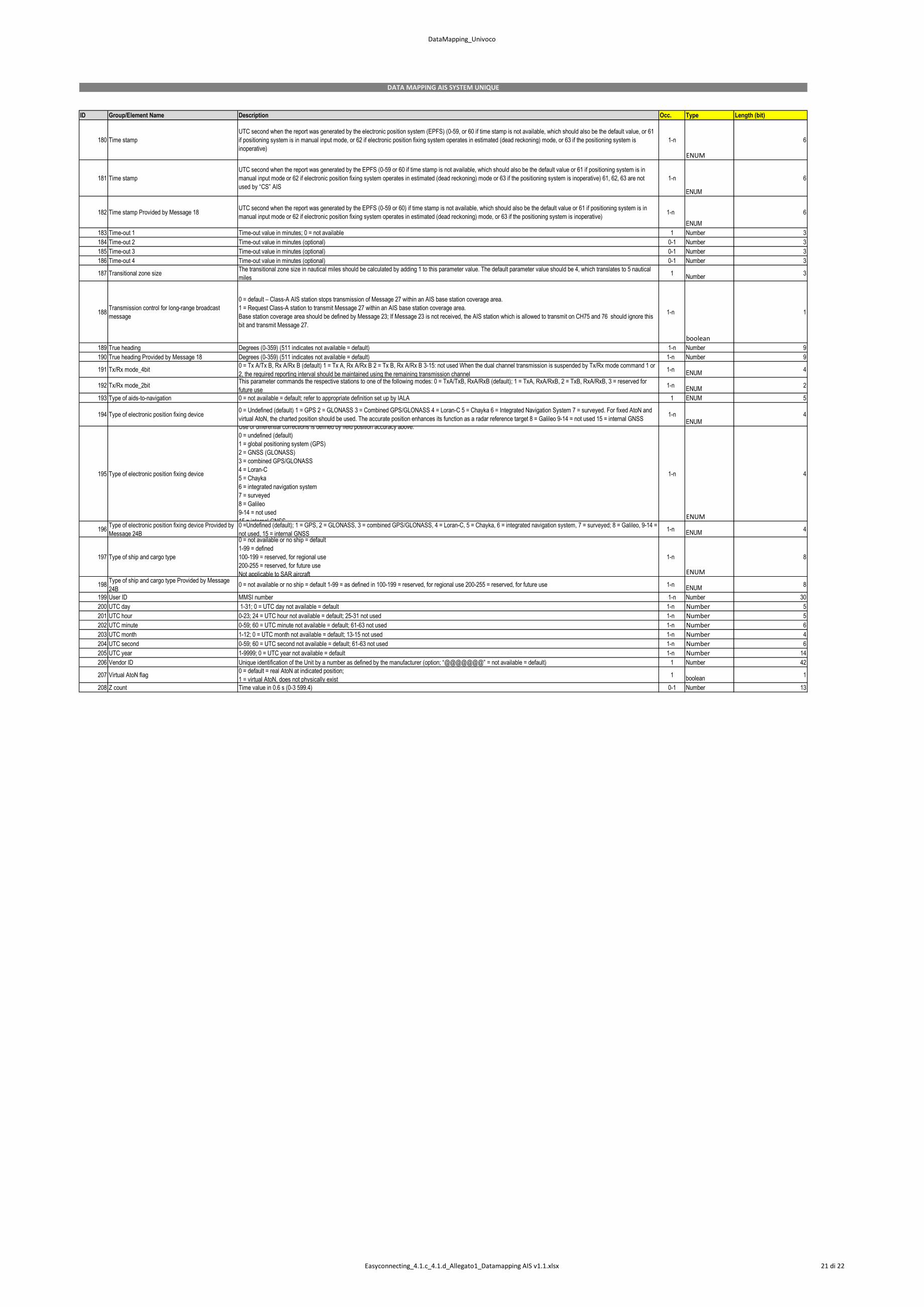
DataMapping_Univoco
ID Group/Element Name Description Occ. Type Length (bit)
DATA MAPPING AIS SYSTEM UNIQUE
180 Time stamp
UTC second when the report was generated by the electronic position system (EPFS) (0-59, or 60 if time stamp is not available, which should also be the default value, or 61
if positioning system is in manual input mode, or 62 if electronic position fixing system operates in estimated (dead reckoning) mode, or 63 if the positioning system is
inoperative)
1-n
ENUM
6
181 Time stamp
UTC second when the report was generated by the EPFS (0-59 or 60 if time stamp is not available, which should also be the default value or 61 if positioning system is in
manual input mode or 62 if electronic position fixing system operates in estimated (dead reckoning) mode or 63 if the positioning system is inoperative) 61, 62, 63 are not
used by “CS” AIS
1-n
ENUM
6
182 Time stamp Provided by Message 18 UTC second when the report was generated by the EPFS (0-59 or 60) if time stamp is not available, which should also be the default value or 61 if positioning system is in
manual input mode or 62 if electronic position fixing system operates in estimated (dead reckoning) mode, or 63 if the positioning system is inoperative) 1-n
ENUM
6
183 Time-out 1 Time-out value in minutes; 0 = not available 1 Number 3
184 Time-out 2 Time-out value in minutes (optional) 0-1 Number 3
185 Time-out 3 Time-out value in minutes (optional) 0-1 Number 3
186 Time-out 4 Time-out value in minutes (optional) 0-1 Number 3
187 Transitional zone size The transitional zone size in nautical miles should be calculated by adding 1 to this parameter value. The default parameter value should be 4, which translates to 5 nautical
miles1
Number3
188Transmission control for long-range broadcast
message
0 = default – Class-A AIS station stops transmission of Message 27 within an AIS base station coverage area.
1 = Request Class-A station to transmit Message 27 within an AIS base station coverage area.
Base station coverage area should be defined by Message 23; If Message 23 is not received, the AIS station which is allowed to transmit on CH75 and 76 should ignore this
bit and transmit Message 27.
1-n
boolean
1
189 True heading Degrees (0-359) (511 indicates not available = default) 1-n Number 9
190 True heading Provided by Message 18 Degrees (0-359) (511 indicates not available = default) 1-n Number 9
191 Tx/Rx mode_4bit0 = Tx A/Tx B, Rx A/Rx B (default) 1 = Tx A, Rx A/Rx B 2 = Tx B, Rx A/Rx B 3-15: not used When the dual channel transmission is suspended by Tx/Rx mode command 1 or
2, the required reporting interval should be maintained using the remaining transmission channel 1-n
ENUM4
192 Tx/Rx mode_2bitThis parameter commands the respective stations to one of the following modes: 0 = TxA/TxB, RxA/RxB (default); 1 = TxA, RxA/RxB, 2 = TxB, RxA/RxB, 3 = reserved for
future use 1-n
ENUM2
193 Type of aids-to-navigation 0 = not available = default; refer to appropriate definition set up by IALA 1 ENUM 5
194 Type of electronic position fixing device 0 = Undefined (default) 1 = GPS 2 = GLONASS 3 = Combined GPS/GLONASS 4 = Loran-C 5 = Chayka 6 = Integrated Navigation System 7 = surveyed. For fixed AtoN and
virtual AtoN, the charted position should be used. The accurate position enhances its function as a radar reference target 8 = Galileo 9-14 = not used 15 = internal GNSS 1-n
ENUM4
195 Type of electronic position fixing device
Use of differential corrections is defined by field position accuracy above:
0 = undefined (default)
1 = global positioning system (GPS)
2 = GNSS (GLONASS)
3 = combined GPS/GLONASS
4 = Loran-C
5 = Chayka
6 = integrated navigation system
7 = surveyed
8 = Galileo
9-14 = not used
15 = internal GNSS
1-n
ENUM
4
196Type of electronic position fixing device Provided by
Message 24B
0 =Undefined (default); 1 = GPS, 2 = GLONASS, 3 = combined GPS/GLONASS, 4 = Loran-C, 5 = Chayka, 6 = integrated navigation system, 7 = surveyed; 8 = Galileo, 9-14 =
not used, 15 = internal GNSS 1-n
ENUM4
197 Type of ship and cargo type
0 = not available or no ship = default
1-99 = defined
100-199 = reserved, for regional use
200-255 = reserved, for future use
Not applicable to SAR aircraft
1-n
ENUM
8
198Type of ship and cargo type Provided by Message
24B 0 = not available or no ship = default 1-99 = as defined in 100-199 = reserved, for regional use 200-255 = reserved, for future use 1-n
ENUM8
199 User ID MMSI number 1-n Number 30
200 UTC day 1-31; 0 = UTC day not available = default 1-n Number 5
201 UTC hour 0-23; 24 = UTC hour not available = default; 25-31 not used 1-n Number 5
202 UTC minute 0-59; 60 = UTC minute not available = default; 61-63 not used 1-n Number 6
203 UTC month 1-12; 0 = UTC month not available = default; 13-15 not used 1-n Number 4
204 UTC second 0-59; 60 = UTC second not available = default; 61-63 not used 1-n Number 6
205 UTC year 1-9999; 0 = UTC year not available = default 1-n Number 14
206 Vendor ID Unique identification of the Unit by a number as defined by the manufacturer (option; “@@@@@@@” = not available = default) 1 Number 42
207 Virtual AtoN flag 0 = default = real AtoN at indicated position;
1 = virtual AtoN, does not physically exist 1
boolean1
208 Z count Time value in 0.6 s (0-3 599.4) 0-1 Number 13
Easyconnecting_4.1.c_4.1.d_Allegato1_Datamapping AIS v1.1.xlsx 21 di 22
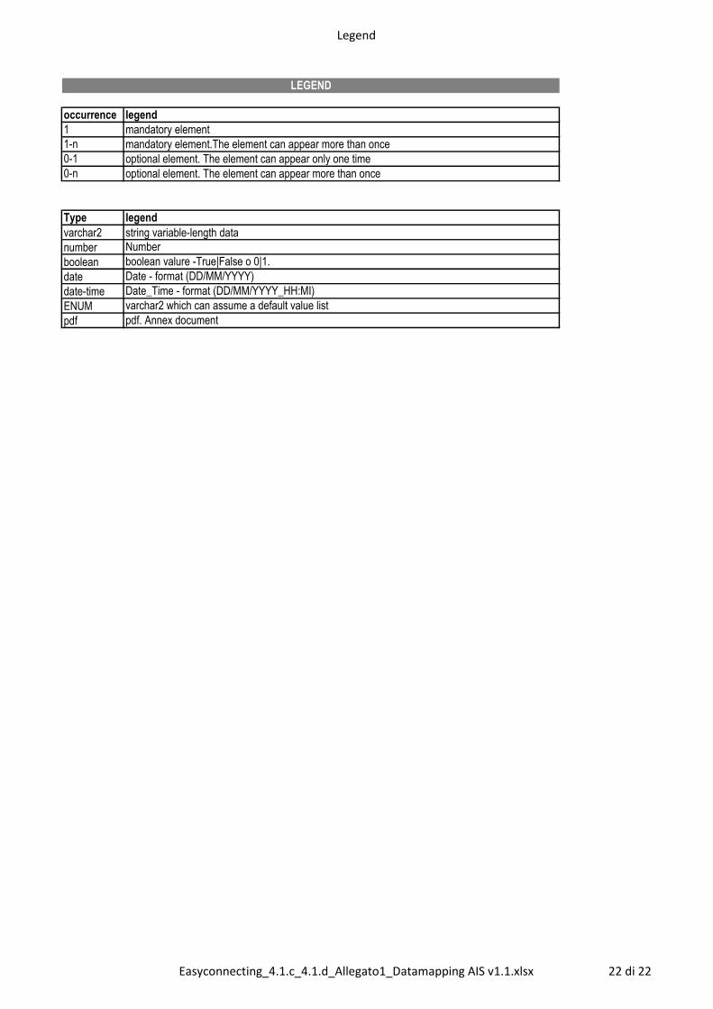
Legend
occurrence legend
1 mandatory element
1-n mandatory element.The element can appear more than once
0-1 optional element. The element can appear only one time
0-n optional element. The element can appear more than once
Type legend
varchar2 string variable-length data
number Number
boolean boolean valure -True|False o 0|1.
date Date - format (DD/MM/YYYY)
date-time Date_Time - format (DD/MM/YYYY_HH:MI)
ENUM varchar2 which can assume a default value list
pdf pdf. Annex document
LEGEND
Easyconnecting_4.1.c_4.1.d_Allegato1_Datamapping AIS v1.1.xlsx 22 di 22
Related Documents