Analysis and Prevention of Microcracking Phenomenon Occurring during Strip Casting of an AISI 304 Stainless Steel MANJIN HA, JUTAE CHOI, SEONGIN JEONG, HEEKYUNG MOON, SUNGHAK LEE, and TAEWOOK KANG This study was concerned with the effects of microstructural parameters on the microcracking phenome- non occurring during strip casting of an AISI 304 stainless steel. Detailed microstructural analyses of the microcracked regions showed that microcracks were formed mainly along tortoise-shell–shaped depressions and that their number and size were considerably reduced when strip casting was done right after a shot-blasting or pickling treatment of the casting roll surface. This microcracking phenome- non was closely related to the formation of a black oxide layer, which was mainly composed of manganese-rich oxides, on the roll surface. The black oxide layer acted as a barrier of thermal transfer between the rolls and melt, led to an increased gas gap and inhomogeneous solidification of cast strips, and, thus, played a role in forming both tortoise-shell–shaped depressions and microcracks on the strip surface. The installation of brush rolls behind the casting rolls was suggested as a method to prevent microcracks, because the brush rolls could continuously scrape off the black oxide layer affixed on the roll surface during strip casting. I. INTRODUCTION surface cracks in cast strips. These cracks can be prevented when homogeneous solidification of strips is induced by AUSTENITIC stainless steels, having excellent (1) intentionally providing homogeneous roughness on the mechanical properties and corrosion resistance, have been casting-roll surface, [6,11–13] (2) using a N 2 gas atmosphere, widely used for tableware, building materials, and materials which has good wettability with the roll surface and good for petrochemical plants. Recently, intensive studies on a solubility in the melt, [6] (3) preventing the inclusion of oxides strip-casting process of these steels have been made to pro- into the melt, [14] and (4) preventing the turbulence of the duce thin strips without hot rolling. [1,2,3] Strip casting offers melt. [14] However, even these methods cannot eliminate many advantages, such as refinement of the solidified struc- microcracks formed along depressions. Microcracks, mostly ture, reduction of microsegregation, and expansion of the hundreds of micrometers long, are not easily visible, but may solubility limit, because solidification occurs much faster grow to be long cracks, which act as defects to deteriorate the than in conventional continuous casting. Strip casting also deformability and corrosion resistance of cast strips. These lowers the production cost by omitting hot-rolling processes microcracks are presumed to be closely related to the pres- and is an environmentally conscious process. Several compa- ence of a gas gap and the inhomogeneous solidification nies have already finished constructing plant facilities for behavior which frequently occurs as solidification shells are commercialization, and new products are currently being in direct contact with casting rolls. Very few studies have developed. [4,5] However, it is required that the quality of the been undertaken on this microcracking during strip casting, surface and the bulk of final cast strips meets the quality particularly in regard to its correlation to microstructure, level of hot-rolled strips produced by continuous casting, microcrack initiation mode, and mechanisms involved; thus, because the rolling ratio available after strip casting is further research on this is required. limited. This study aimed at identifying the causes of the micro- Critical quality problems arising from strip casting include cracking phenomenon through microstructural analyses of surface cracks, tortoise-shell–shaped depressions, and microcracks formed during strip casting of an AISI 304 microcracks formed along the depressions. [6–9] The thickness stainless steel, a representative austenitic stainless steel. For of solidification shells becomes uneven due to inhomoge- this purpose, the microcracked region of cast strips was neous solidification and thermal contraction, and trans- examined, and the results were compared with those of formation strains are concentrated in thin regions of the uncracked strips in relation to the solidification behavior, solidification shells, [10] thereby leading to the initiation of in order to identify strip-casting conditions under which microcracking can be prevented. MANJIN HA, JUTAE CHOI, and SEONGIN JEONG, Research Engineers, HEEKYUNG MOON, Senior Research Engineer, and TAEWOOK KANG, II. EXPERIMENTAL General Manager, are with the Strip Casting Project Team, Research Institute of Industrial Science and Technology, Pohang 790-600, Korea, SUNGHAK The AISI 304 stainless steel (chemical composition: LEE, Professor, Center for Advanced Aerospace Materials, Pohang University 0.044C-18.3Cr-8.2Ni-0.045Si-0.9Mn-Fe (wt pct)) used in of Science and Technology, Pohang 790-784, Korea, is jointly appointed with this study featured an equilibrium phase of austenite (g ) and the Materials Science and Engineering Department, Pohang University of a small amount of nonequilibrium phase of d ferrite, which Science and Technology. Contact e-mail: [email protected] Manuscript submitted July 19, 2001. were formed by reactions of L → L 1 d → L 1 d 1 g → METALLURGICAL AND MATERIALS TRANSACTIONS A VOLUME 33A, MAY 2002—1487

Welcome message from author
This document is posted to help you gain knowledge. Please leave a comment to let me know what you think about it! Share it to your friends and learn new things together.
Transcript
Analysis and Prevention of Microcracking PhenomenonOccurring during Strip Casting of an AISI 304 StainlessSteel
MANJIN HA, JUTAE CHOI, SEONGIN JEONG, HEEKYUNG MOON, SUNGHAK LEE, andTAEWOOK KANG
This study was concerned with the effects of microstructural parameters on the microcracking phenome-non occurring during strip casting of an AISI 304 stainless steel. Detailed microstructural analysesof the microcracked regions showed that microcracks were formed mainly along tortoise-shell–shapeddepressions and that their number and size were considerably reduced when strip casting was doneright after a shot-blasting or pickling treatment of the casting roll surface. This microcracking phenome-non was closely related to the formation of a black oxide layer, which was mainly composed ofmanganese-rich oxides, on the roll surface. The black oxide layer acted as a barrier of thermal transferbetween the rolls and melt, led to an increased gas gap and inhomogeneous solidification of caststrips, and, thus, played a role in forming both tortoise-shell–shaped depressions and microcracks onthe strip surface. The installation of brush rolls behind the casting rolls was suggested as a methodto prevent microcracks, because the brush rolls could continuously scrape off the black oxide layeraffixed on the roll surface during strip casting.
I. INTRODUCTION surface cracks in cast strips. These cracks can be preventedwhen homogeneous solidification of strips is induced byAUSTENITIC stainless steels, having excellent(1) intentionally providing homogeneous roughness on themechanical properties and corrosion resistance, have beencasting-roll surface,[6,11–13] (2) using a N2 gas atmosphere,widely used for tableware, building materials, and materialswhich has good wettability with the roll surface and goodfor petrochemical plants. Recently, intensive studies on asolubility in the melt,[6] (3) preventing the inclusion of oxidesstrip-casting process of these steels have been made to pro-into the melt,[14] and (4) preventing the turbulence of theduce thin strips without hot rolling.[1,2,3] Strip casting offersmelt.[14] However, even these methods cannot eliminatemany advantages, such as refinement of the solidified struc-microcracks formed along depressions. Microcracks, mostlyture, reduction of microsegregation, and expansion of thehundreds of micrometers long, are not easily visible, but maysolubility limit, because solidification occurs much fastergrow to be long cracks, which act as defects to deteriorate thethan in conventional continuous casting. Strip casting alsodeformability and corrosion resistance of cast strips. Theselowers the production cost by omitting hot-rolling processesmicrocracks are presumed to be closely related to the pres-and is an environmentally conscious process. Several compa-ence of a gas gap and the inhomogeneous solidificationnies have already finished constructing plant facilities forbehavior which frequently occurs as solidification shells arecommercialization, and new products are currently beingin direct contact with casting rolls. Very few studies havedeveloped.[4,5] However, it is required that the quality of thebeen undertaken on this microcracking during strip casting,surface and the bulk of final cast strips meets the qualityparticularly in regard to its correlation to microstructure,level of hot-rolled strips produced by continuous casting,microcrack initiation mode, and mechanisms involved; thus,because the rolling ratio available after strip casting isfurther research on this is required.limited.
This study aimed at identifying the causes of the micro-Critical quality problems arising from strip casting includecracking phenomenon through microstructural analyses ofsurface cracks, tortoise-shell–shaped depressions, andmicrocracks formed during strip casting of an AISI 304microcracks formed along the depressions.[6–9] The thicknessstainless steel, a representative austenitic stainless steel. Forof solidification shells becomes uneven due to inhomoge-this purpose, the microcracked region of cast strips wasneous solidification and thermal contraction, and trans-examined, and the results were compared with those offormation strains are concentrated in thin regions of theuncracked strips in relation to the solidification behavior,solidification shells,[10] thereby leading to the initiation ofin order to identify strip-casting conditions under whichmicrocracking can be prevented.
MANJIN HA, JUTAE CHOI, and SEONGIN JEONG, Research Engineers,HEEKYUNG MOON, Senior Research Engineer, and TAEWOOK KANG, II. EXPERIMENTALGeneral Manager, are with the Strip Casting Project Team, Research Instituteof Industrial Science and Technology, Pohang 790-600, Korea, SUNGHAK The AISI 304 stainless steel (chemical composition:LEE, Professor, Center for Advanced Aerospace Materials, Pohang University 0.044C-18.3Cr-8.2Ni-0.045Si-0.9Mn-Fe (wt pct)) used inof Science and Technology, Pohang 790-784, Korea, is jointly appointed with this study featured an equilibrium phase of austenite (g ) andthe Materials Science and Engineering Department, Pohang University of
a small amount of nonequilibrium phase of d ferrite, whichScience and Technology. Contact e-mail: [email protected] submitted July 19, 2001. were formed by reactions of L → L 1 d → L 1 d 1 g →
METALLURGICAL AND MATERIALS TRANSACTIONS A VOLUME 33A, MAY 2002—1487
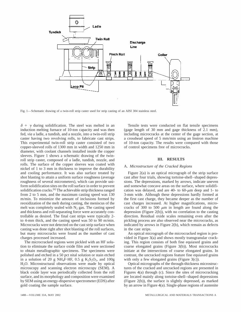
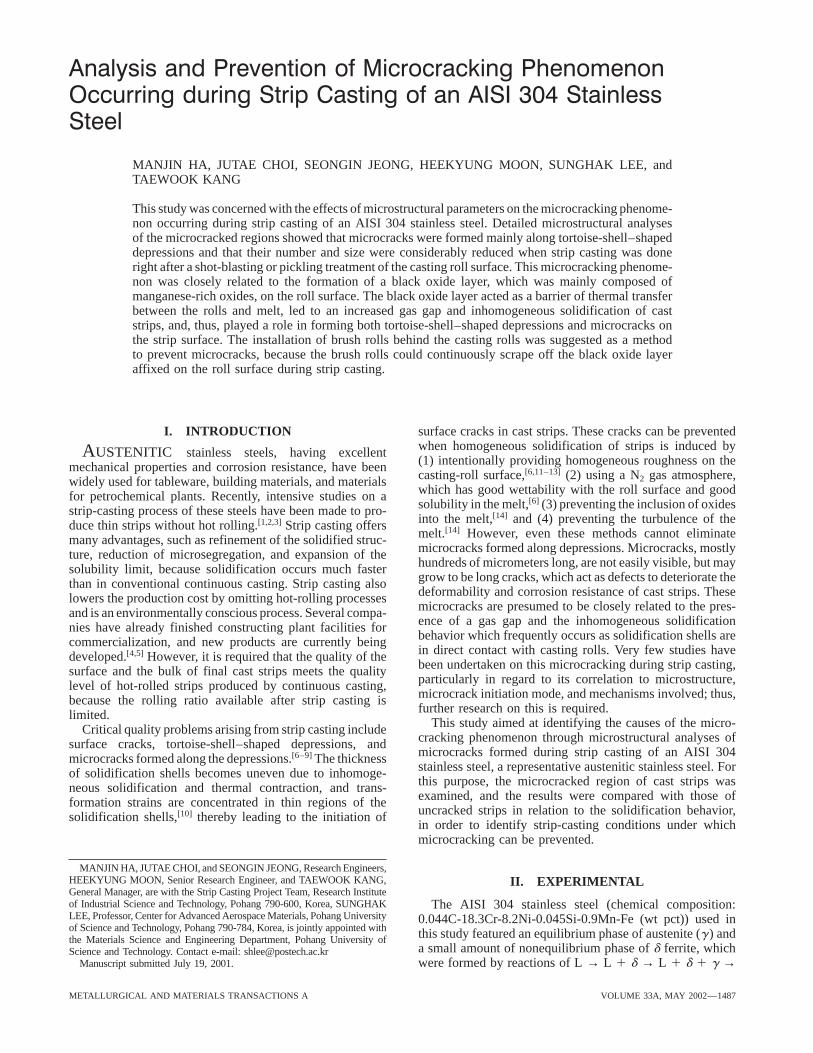
Fig. 1—Schematic drawing of a twin-roll strip caster used for strip casting of an AISI 304 stainless steel.
d 1 g during solidification. The steel was melted in an Tensile tests were conducted on flat tensile specimens(gage length of 30 mm and gage thickness of 2.1 mm),induction melting furnace of 10-ton capacity and was then
fed, via a ladle, a tundish, and a nozzle, into a twin-roll strip including microcracks at the center of the gage section, ata crosshead speed of 5 mm/min using an Instron machinecaster having two revolving rolls, to fabricate cast strips.
This experimental twin-roll strip caster consisted of two of 10-ton capacity. The results were compared with thoseof control specimens free of microcracks.copper-sleeved rolls of 1300 mm in width and 1250 mm in
diameter, with coolant channels installed inside the coppersleeves. Figure 1 shows a schematic drawing of the twin-
III. RESULTSroll strip caster, composed of a ladle, tundish, nozzle, androlls. The surface of the copper sleeves was coated with A. Microstructure of the Cracked Regionsnickel of 1 to 3 mm in thickness to improve the durabilityand cooling performance. It was also surface treated by Figure 2(a) is an optical micrograph of the strip surface
cast after four trials, showing tortoise-shell–shaped depres-shot blasting to attain a uniform surface roughness (averageroughness of several micrometers), which can provide uni- sions. The depressions, marked by arrows, indicate uneven
and somewhat concave areas on the surface, where solidifi-form solidification sites on the roll surface in order to preventsolidification cracks.[6] The achievable strip thickness ranged cation was delayed, and are 40- to 60-mm deep and 1- to
3-mm wide. Although these depressions hardly formed atfrom 2 to 5 mm, and the maximum casting speed was 130m/min. To minimize the amount of inclusions formed by the first cast charge, they became deeper as the number of
cast charges increased. At higher magnifications, micro-reoxidization of the melt during casting, the meniscus of themelt was completely sealed with N2 gas. The casting speed cracks of 300 to 500 mm in length are found along the
depression (Figure 2(b)), with no correlation to the castingand thickness and roll-separating force were accurately con-trollable as desired. The final cast strips were typically 2- direction. Residual oxide scales remaining even after the
pickling process are also observed near the microcracks, asto 4-mm thick, and the casting speed was 50 to 90 m/min.Microcracks were not detected on the cast strip surface when indicated by arrows in Figure 2(b), which remain as defects
in the cast strips.casting was done right after shot blasting of the roll surfaces,but many microcracks were found as the number of cast An optical micrograph of the microcracked region is pro-
vided in Figure 3(a) and shows mostly transgranular crack-charges processed increased.The microcracked regions were pickled with an HF solu- ing. This region consists of both fine equiaxed grains and
coarse elongated grains (Figure 3(b)). Most microcrackstion to eliminate the surface oxide film and were sectionedto obtain metallographic specimens. The specimens were initiate at the intersections of coarse elongated grains. In
contrast, the uncracked regions feature fine equiaxed grainspolished and etched in a 50 pct nital solution or stain etchedin a solution of 20 g NH4F?HF, 0.5 g K2S2O5, and 100g with only a few elongated grains (Figure 3(c)).
Optical micrographs of the through-thickness microstruc-H2O. Microstructural observations were made by opticalmicroscopy and scanning electron microscopy (SEM). A tures of the cracked and uncracked regions are presented in
Figures 4(a) through (c). Since the sites of microcrackingblack oxide layer was periodically collected from the rollsurface, and its morphology and composition were examined are located mainly along tortoise-shell–shaped depressions
(Figure 2(b)), the surface is slightly depressed, as markedby SEM using an energy-dispersive spectrometer (EDS) aftergold coating the sample surface. by an arrow in Figure 4(a). Single-phase regions of austenite
1488—VOLUME 33A, MAY 2002 METALLURGICAL AND MATERIALS TRANSACTIONS A
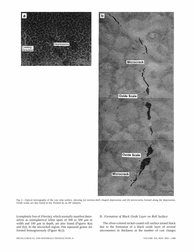
Fig. 2—Optical micrographs of the cast strip surface, showing (a) tortoise-shell–shaped depressions and (b) microcracks formed along the depressions.Oxide scales are also found in (b). Pickled by an HF solution.
(completely free of d ferrite), which normally manifest them- B. Formation of Black Oxide Layer on Roll Surfaceselves as semispherical white spots of 300 to 500 mm in
The silver-colored nickel-coated roll surface turned blackwidth and 100 mm in depth, are also found (Figures 4(a)due to the formation of a black oxide layer of severaland (b)). In the uncracked region, fine equiaxed grains are
formed homogeneously (Figure 4(c)). micrometers in thickness as the number of cast charges
METALLURGICAL AND MATERIALS TRANSACTIONS A VOLUME 33A, MAY 2002—1489
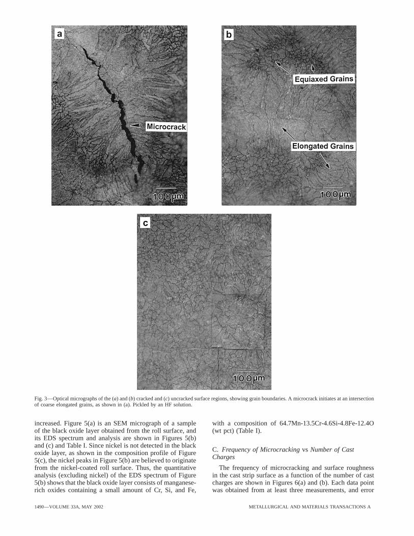
Fig. 3—Optical micrographs of the (a) and (b) cracked and (c) uncracked surface regions, showing grain boundaries. A microcrack initiates at an intersectionof coarse elongated grains, as shown in (a). Pickled by an HF solution.
increased. Figure 5(a) is an SEM micrograph of a sample with a composition of 64.7Mn-13.5Cr-4.6Si-4.8Fe-12.4O(wt pct) (Table I).of the black oxide layer obtained from the roll surface, and
its EDS spectrum and analysis are shown in Figures 5(b)and (c) and Table I. Since nickel is not detected in the black
C. Frequency of Microcracking vs Number of Castoxide layer, as shown in the composition profile of FigureCharges5(c), the nickel peaks in Figure 5(b) are believed to originate
from the nickel-coated roll surface. Thus, the quantitative The frequency of microcracking and surface roughnessin the cast strip surface as a function of the number of castanalysis (excluding nickel) of the EDS spectrum of Figure
5(b) shows that the black oxide layer consists of manganese- charges are shown in Figures 6(a) and (b). Each data pointwas obtained from at least three measurements, and errorrich oxides containing a small amount of Cr, Si, and Fe,
1490—VOLUME 33A, MAY 2002 METALLURGICAL AND MATERIALS TRANSACTIONS A
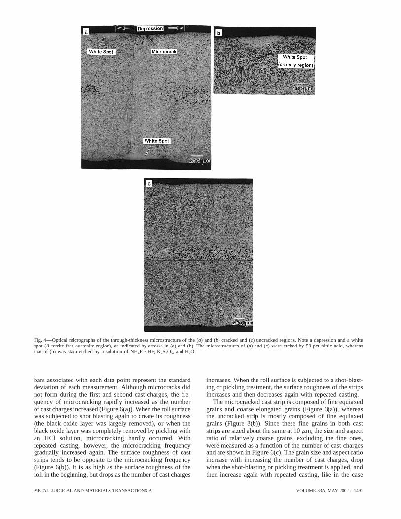
Fig. 4—Optical micrographs of the through-thickness microstructure of the (a) and (b) cracked and (c) uncracked regions. Note a depression and a whitespot (d -ferrite-free austenite region), as indicated by arrows in (a) and (b). The microstructures of (a) and (c) were etched by 50 pct nitric acid, whereasthat of (b) was stain-etched by a solution of NH4F ? HF, K2S2O5, and H2O.
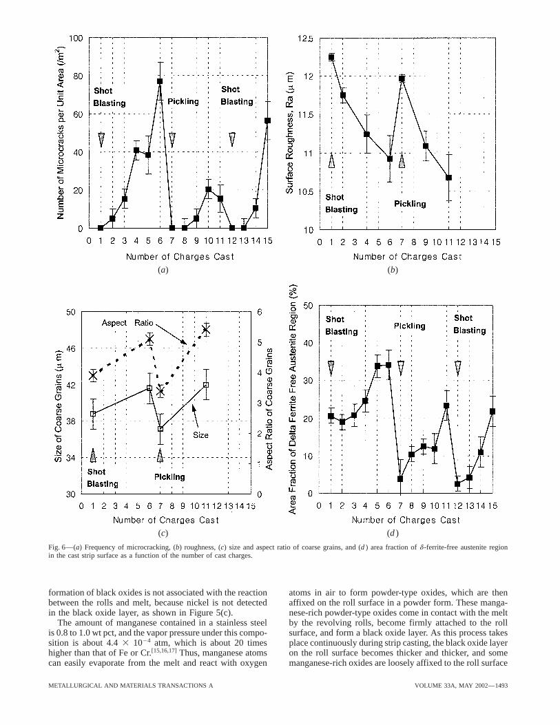
bars associated with each data point represent the standard increases. When the roll surface is subjected to a shot-blast-ing or pickling treatment, the surface roughness of the stripsdeviation of each measurement. Although microcracks did
not form during the first and second cast charges, the fre- increases and then decreases again with repeated casting.The microcracked cast strip is composed of fine equiaxedquency of microcracking rapidly increased as the number
of cast charges increased (Figure 6(a)). When the roll surface grains and coarse elongated grains (Figure 3(a)), whereasthe uncracked strip is mostly composed of fine equiaxedwas subjected to shot blasting again to create its roughness
(the black oxide layer was largely removed), or when the grains (Figure 3(b)). Since these fine grains in both caststrips are sized about the same at 10 mm, the size and aspectblack oxide layer was completely removed by pickling with
an HCl solution, microcracking hardly occurred. With ratio of relatively coarse grains, excluding the fine ones,were measured as a function of the number of cast chargesrepeated casting, however, the microcracking frequency
gradually increased again. The surface roughness of cast and are shown in Figure 6(c). The grain size and aspect ratioincrease with increasing the number of cast charges, dropstrips tends to be opposite to the microcracking frequency
(Figure 6(b)). It is as high as the surface roughness of the when the shot-blasting or pickling treatment is applied, andthen increase again with repeated casting, like in the caseroll in the beginning, but drops as the number of cast charges
METALLURGICAL AND MATERIALS TRANSACTIONS A VOLUME 33A, MAY 2002—1491
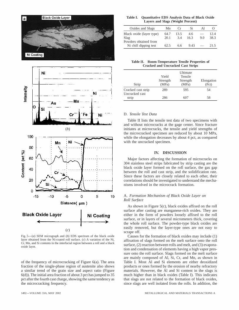
Table I. Quantitative EDS Analysis Data of Black OxideLayers and Slags (Weight Percent)
Oxides and Slags Mn Cr Si Al O
Black oxide (layer type) 64.7 13.5 4.6 — 12.4Slag 20.1 3.4 16.3 9.0 38.3Powders obtained from
Ni chill dipping test 62.5 6.6 9.43 — 21.5
Table II. Room-Temperature Tensile Properties ofCracked and Uncracked Cast Strips
UltimateYield Tensile
Strength Strength ElongationStrip (MPa) (MPa) (Pct)
Cracked cast strip 289 595 54Uncracked cast
strip 286 607 58
D. Tensile Test Data
Table II lists the tensile test data of two specimens withand without microcracks at the gage center. Since fractureinitiates at microcracks, the tensile and yield strengths of(b)the microcracked specimen are reduced by about 10 MPa,while the elongation decreases by about 4 pct, as comparedwith the uncracked specimen.
IV. DISCUSSION
Major factors affecting the formation of microcracks on304 stainless steel strips fabricated by strip casting are theblack oxide layer formed on the roll surface, the gas gapbetween the roll and cast strip, and the solidification rate.Since these factors are closely related to each other, theircorrelations should be investigated to understand the mecha-nisms involved in the microcrack formation.
A. Formation Mechanism of Black Oxide Layer onRoll Surface
As shown in Figure 5(c), black oxides affixed on the rollsurface after casting are manganese-rich oxides. They areeither in the form of powders loosely affixed to the rollsurface, or in layers of several micrometers thick, coveringthe whole roll surface. The powder-type black oxides areeasily removed, but the layer-type ones are not easy to
(c) scrape off.Fig. 5—(a) SEM micrograph and (b) EDS spectrum of the black oxide Causes for the formation of black oxides may include (1)layer obtained from the Ni-coated roll surface. (c) A variation of the Ni, affixation of slags formed on the melt surface onto the rollCr, Mn, and Si contents in the interfacial region between a roll and a black surface, (2) reaction between rolls and melt, and (3) evapora-oxide layer.
tion and condensation of elements having a high vapor pres-sure onto the roll surface. Slags formed on the melt surfaceare mainly composed of Al, Si, Cr, and Mn, as shown inTable I. Most Al and Si elements are either deoxidizedof the frequency of microcracking of Figure 6(a). The area
fraction of the single-phase region of austenite also shows products or ones formed by the erosion of nearby refractorymaterials. However, the Al and Si content in the slags isa similar trend of the grain size and aspect ratio (Figure
6(d)). The initial area fraction of about 3 pct has jumped to 35 much higher than in black oxides (Table I). This indicatesthat slags are not related to the formation of black oxides,pct after the fourth cast charge, showing the same tendency as
the microcracking frequency. since slags are well isolated from the rolls. In addition, the
1492—VOLUME 33A, MAY 2002 METALLURGICAL AND MATERIALS TRANSACTIONS A
(a) (b)
(c) (d )
Fig. 6—(a) Frequency of microcracking, (b) roughness, (c) size and aspect ratio of coarse grains, and (d ) area fraction of d -ferrite-free austenite regionin the cast strip surface as a function of the number of cast charges.
formation of black oxides is not associated with the reaction atoms in air to form powder-type oxides, which are thenaffixed on the roll surface in a powder form. These manga-between the rolls and melt, because nickel is not detected
in the black oxide layer, as shown in Figure 5(c). nese-rich powder-type oxides come in contact with the meltby the revolving rolls, become firmly attached to the rollThe amount of manganese contained in a stainless steel
is 0.8 to 1.0 wt pct, and the vapor pressure under this compo- surface, and form a black oxide layer. As this process takesplace continuously during strip casting, the black oxide layersition is about 4.4 3 1024 atm, which is about 20 times
higher than that of Fe or Cr.[15,16,17] Thus, manganese atoms on the roll surface becomes thicker and thicker, and somemanganese-rich oxides are loosely affixed to the roll surfacecan easily evaporate from the melt and react with oxygen
METALLURGICAL AND MATERIALS TRANSACTIONS A VOLUME 33A, MAY 2002—1493
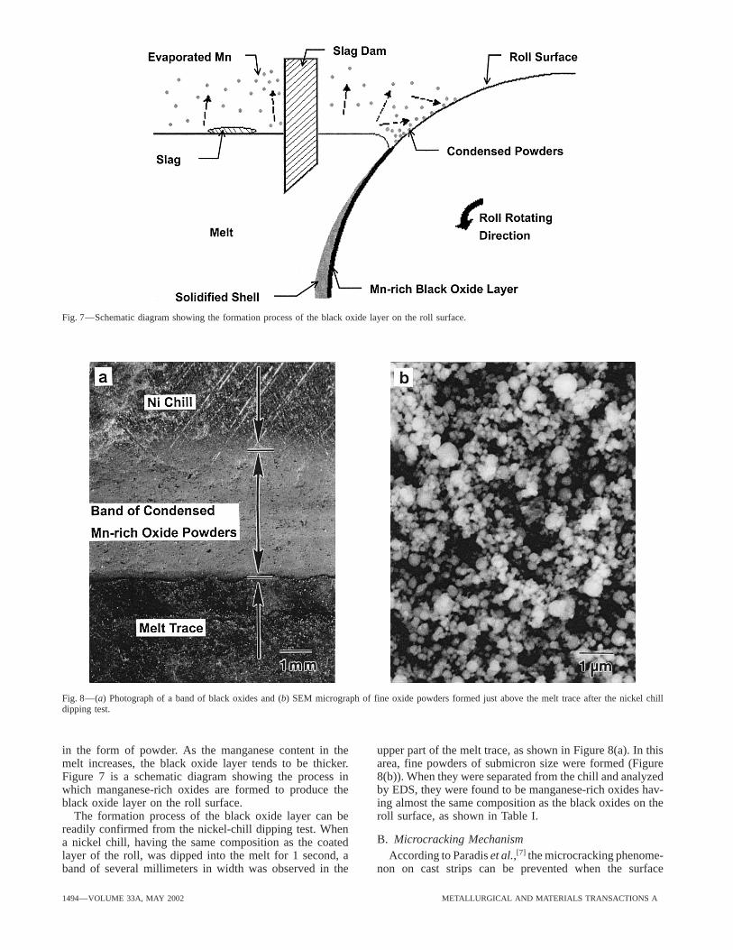
Fig. 7—Schematic diagram showing the formation process of the black oxide layer on the roll surface.
Fig. 8—(a) Photograph of a band of black oxides and (b) SEM micrograph of fine oxide powders formed just above the melt trace after the nickel chilldipping test.
in the form of powder. As the manganese content in the upper part of the melt trace, as shown in Figure 8(a). In thisarea, fine powders of submicron size were formed (Figuremelt increases, the black oxide layer tends to be thicker.
Figure 7 is a schematic diagram showing the process in 8(b)). When they were separated from the chill and analyzedby EDS, they were found to be manganese-rich oxides hav-which manganese-rich oxides are formed to produce the
black oxide layer on the roll surface. ing almost the same composition as the black oxides on theroll surface, as shown in Table I.The formation process of the black oxide layer can be
readily confirmed from the nickel-chill dipping test. WhenB. Microcracking Mechanisma nickel chill, having the same composition as the coated
layer of the roll, was dipped into the melt for 1 second, a According to Paradis et al.,[7] the microcracking phenome-non on cast strips can be prevented when the surfaceband of several millimeters in width was observed in the
1494—VOLUME 33A, MAY 2002 METALLURGICAL AND MATERIALS TRANSACTIONS A
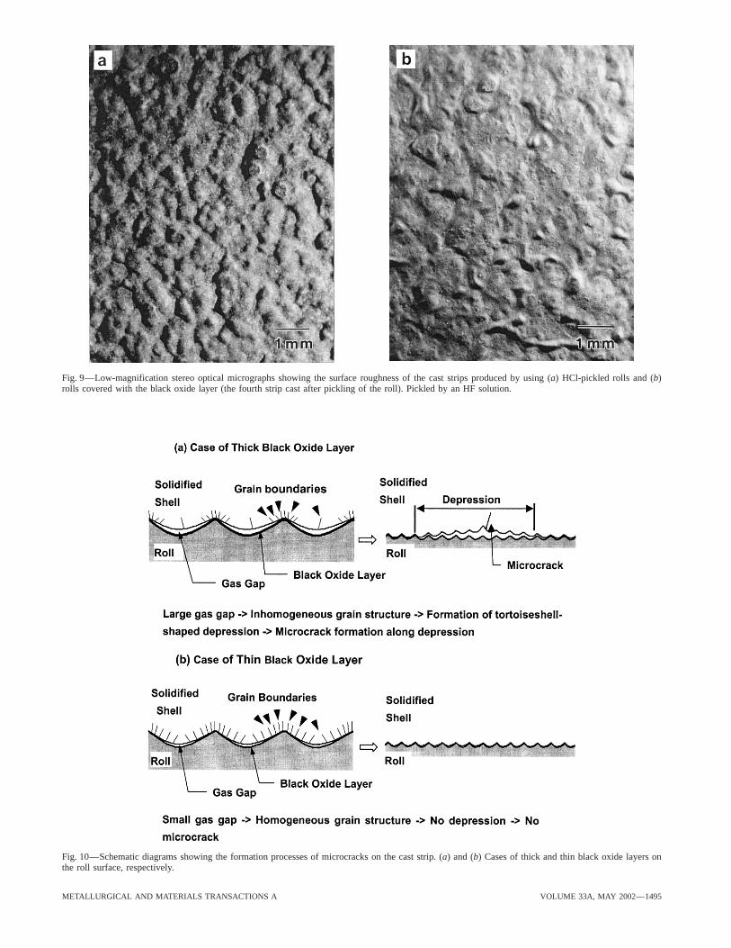
Fig. 9—Low-magnification stereo optical micrographs showing the surface roughness of the cast strips produced by using (a) HCl-pickled rolls and (b)rolls covered with the black oxide layer (the fourth strip cast after pickling of the roll). Pickled by an HF solution.
Fig. 10—Schematic diagrams showing the formation processes of microcracks on the cast strip. (a) and (b) Cases of thick and thin black oxide layers onthe roll surface, respectively.
METALLURGICAL AND MATERIALS TRANSACTIONS A VOLUME 33A, MAY 2002—1495
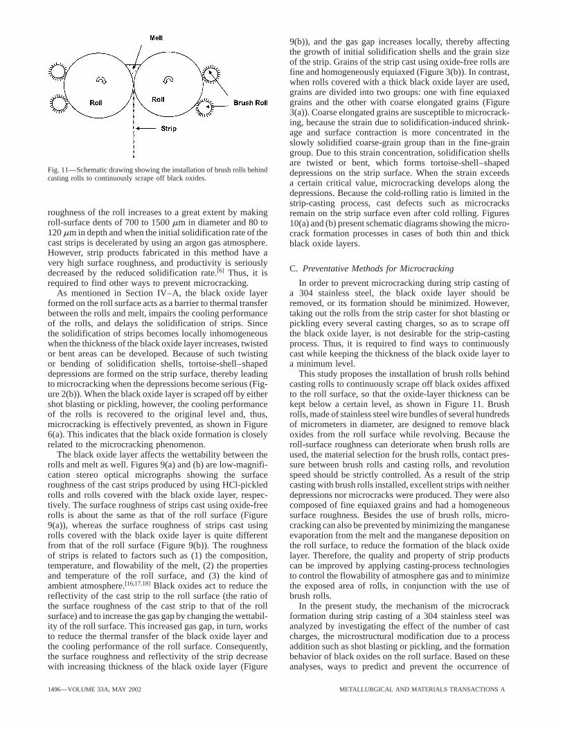
9(b)), and the gas gap increases locally, thereby affectingthe growth of initial solidification shells and the grain sizeof the strip. Grains of the strip cast using oxide-free rolls arefine and homogeneously equiaxed (Figure 3(b)). In contrast,when rolls covered with a thick black oxide layer are used,grains are divided into two groups: one with fine equiaxedgrains and the other with coarse elongated grains (Figure3(a)). Coarse elongated grains are susceptible to microcrack-ing, because the strain due to solidification-induced shrink-age and surface contraction is more concentrated in theslowly solidified coarse-grain group than in the fine-graingroup. Due to this strain concentration, solidification shellsare twisted or bent, which forms tortoise-shell–shaped
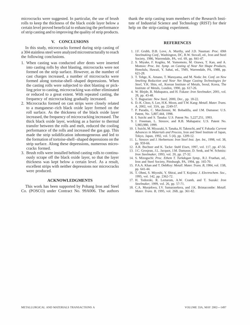
Fig. 11—Schematic drawing showing the installation of brush rolls behind depressions on the strip surface. When the strain exceedscasting rolls to continuously scrape off black oxides.
a certain critical value, microcracking develops along thedepressions. Because the cold-rolling ratio is limited in thestrip-casting process, cast defects such as microcracks
roughness of the roll increases to a great extent by making remain on the strip surface even after cold rolling. Figuresroll-surface dents of 700 to 1500 mm in diameter and 80 to 10(a) and (b) present schematic diagrams showing the micro-120 mm in depth and when the initial solidification rate of the crack formation processes in cases of both thin and thickcast strips is decelerated by using an argon gas atmosphere. black oxide layers.However, strip products fabricated in this method have avery high surface roughness, and productivity is seriously
C. Preventative Methods for Microcrackingdecreased by the reduced solidification rate.[6] Thus, it isrequired to find other ways to prevent microcracking. In order to prevent microcracking during strip casting of
a 304 stainless steel, the black oxide layer should beAs mentioned in Section IV–A, the black oxide layerformed on the roll surface acts as a barrier to thermal transfer removed, or its formation should be minimized. However,
taking out the rolls from the strip caster for shot blasting orbetween the rolls and melt, impairs the cooling performanceof the rolls, and delays the solidification of strips. Since pickling every several casting charges, so as to scrape off
the black oxide layer, is not desirable for the strip-castingthe solidification of strips becomes locally inhomogeneouswhen the thickness of the black oxide layer increases, twisted process. Thus, it is required to find ways to continuously
cast while keeping the thickness of the black oxide layer toor bent areas can be developed. Because of such twistingor bending of solidification shells, tortoise-shell–shaped a minimum level.
This study proposes the installation of brush rolls behinddepressions are formed on the strip surface, thereby leadingto microcracking when the depressions become serious (Fig- casting rolls to continuously scrape off black oxides affixed
to the roll surface, so that the oxide-layer thickness can beure 2(b)). When the black oxide layer is scraped off by eithershot blasting or pickling, however, the cooling performance kept below a certain level, as shown in Figure 11. Brush
rolls, made of stainless steel wire bundles of several hundredsof the rolls is recovered to the original level and, thus,microcracking is effectively prevented, as shown in Figure of micrometers in diameter, are designed to remove black
oxides from the roll surface while revolving. Because the6(a). This indicates that the black oxide formation is closelyrelated to the microcracking phenomenon. roll-surface roughness can deteriorate when brush rolls are
used, the material selection for the brush rolls, contact pres-The black oxide layer affects the wettability between therolls and melt as well. Figures 9(a) and (b) are low-magnifi- sure between brush rolls and casting rolls, and revolution
speed should be strictly controlled. As a result of the stripcation stereo optical micrographs showing the surfaceroughness of the cast strips produced by using HCl-pickled casting with brush rolls installed, excellent strips with neither
depressions nor microcracks were produced. They were alsorolls and rolls covered with the black oxide layer, respec-tively. The surface roughness of strips cast using oxide-free composed of fine equiaxed grains and had a homogeneous
surface roughness. Besides the use of brush rolls, micro-rolls is about the same as that of the roll surface (Figure9(a)), whereas the surface roughness of strips cast using cracking can also be prevented by minimizing the manganese
evaporation from the melt and the manganese deposition onrolls covered with the black oxide layer is quite differentfrom that of the roll surface (Figure 9(b)). The roughness the roll surface, to reduce the formation of the black oxide
layer. Therefore, the quality and property of strip productsof strips is related to factors such as (1) the composition,temperature, and flowability of the melt, (2) the properties can be improved by applying casting-process technologies
to control the flowability of atmosphere gas and to minimizeand temperature of the roll surface, and (3) the kind ofambient atmosphere.[16,17,18] Black oxides act to reduce the the exposed area of rolls, in conjunction with the use of
brush rolls.reflectivity of the cast strip to the roll surface (the ratio ofthe surface roughness of the cast strip to that of the roll In the present study, the mechanism of the microcrack
formation during strip casting of a 304 stainless steel wassurface) and to increase the gas gap by changing the wettabil-ity of the roll surface. This increased gas gap, in turn, works analyzed by investigating the effect of the number of cast
charges, the microstructural modification due to a processto reduce the thermal transfer of the black oxide layer andthe cooling performance of the roll surface. Consequently, addition such as shot blasting or pickling, and the formation
behavior of black oxides on the roll surface. Based on thesethe surface roughness and reflectivity of the strip decreasewith increasing thickness of the black oxide layer (Figure analyses, ways to predict and prevent the occurrence of
1496—VOLUME 33A, MAY 2002 METALLURGICAL AND MATERIALS TRANSACTIONS A
microcracks were suggested. In particular, the use of brush thank the strip casting team members of the Research Insti-tute of Industrial Science and Technology (RIST) for theirrolls to keep the thickness of the black oxide layer below a
certain level proved beneficial to enhancing the performance help on the strip-casting experiment.of strip casting and to improving the quality of strip products.
V. CONCLUSIONS REFERENCESIn this study, microcracks formed during strip casting of
1. J.F. Grubb, D.B. Love, A. Murthy, and J.D. Nauman: Proc. 69tha 304 stainless steel were analyzed microstructurally to reachSteelmaking Conf., Washington, DC, R.W. Stovall, ed., Iron and Steelthe following conclusions. Society, 1986, Warrendale, PA, vol. 69, pp. 841-47.
2. S. Miyake, F. Kogiku, M. Yumomoto, M. Ozawa, T. Kan, and A.1. When casting was conducted after dents were insertedMomoo: Proc. Int. Symp. on Casting of Near Net Shape Products,into casting rolls by shot blasting, microcracks were notHonolulu, Hawaii, Y. Sahai, ed., TMS, Warrendale, PA, 1988, pp.
formed on the strip surface. However, as the number of 621-28.cast charges increased, a number of microcracks were 3. T. Tohge, K. Amano, T. Maruyama, and M. Noda: Int. Conf. on New
Smelting Reduction and Near Net Shape Casting Technologies forformed along tortoise-shell–shaped depressions. WhenSteel, Y.K. Shin, ed., Korean Institute of Metals, Seoul, Korea, Thethe casting rolls were subjected to shot blasting or pick-Institute of Metals, London, 1990, pp. 617-26.ling prior to casting, microcracking was either eliminated 4. W. Blejde, R. Mahapatra, and H. Fukase: Iron Steelmaker, 2001, vol.
or reduced to a great extent. With repeated casting, the 28, pp. 43-48.5. T. Bagsarian: New Steel, 2000, Dec., pp. 18-22.frequency of microcracking gradually increased.6. D.-K. Choo, S. Lee, H.K. Moon, and T.W. Kang: Metall. Mater. Trans.2. Microcracks formed on cast strips were closely related
A, 2002, vol. 33A, pp. 2249-57.to a manganese–rich black oxide layer formed on the7. P. Paradis, C. Marchionni, M. Bobadilla, and J.M. Damasse: U.S.
roll surface. As the thickness of the black oxide layer Patent, No. 5,807,444, 1998.increased, the frequency of microcracking increased. The 8. I. Suichi and S. Tanaka: U.S. Patent No. 5,227,251, 1993.
9. J. Freeman, L. Strezov, and R.B. Mahapatra: U.S. Patent No.thick black oxide layer, working as a barrier to thermal5,983,980, 1999.transfer between the rolls and melt, reduced the cooling
10. I. Suichi, M. Miyazaki, S. Tanaka, H. Takeuchi, and Y. Fukuda: Currentperformance of the rolls and increased the gas gap. This Advances in Materials and Process, Iron and Steel Institute of Japan,made the strip solidification inhomogeneous and led to Tokyo, Japan, 1992, vol. 5 (4), pp. 1209-12.
11. L. Strezov and J. Herbertson: Iron Steel Inst. Jpn. Int., 1998, vol. 38,the formation of tortoise-shell–shaped depressions on thepp. 959-66.strip surface. Along these depressions, numerous micro-
12. A.R. Buchner and K. Tacke: Stahl Eisen, 1997, vol. 117, pp. 47-56.cracks formed.13. J.C. Grosjean, J.L. Jacquot, J.M. Damasse, D. Senk, and W. Schmitz:
3. Brush rolls were installed behind casting rolls to continu- Iron Steelmaker, 1993, vol. 20, pp. 27-32.ously scrape off the black oxide layer, so that the layer 14. S. Mizoguchi: Proc. Ethem T. Turkdogan Symp., R.J. Fruehan, ed.,
Iron and Steel Society, Pittsburgh, PA, 1994, pp. 165-70.thickness was kept below a certain level. As a result,15. P.A.A. Khan and T. DebRoy: Metall. Mater. Trans. B, 1984, vol. 15B,excellent strips with neither depressions nor microcracks
pp. 641-44.were produced. 16. T. Ohmi, S. Miyoshi, Y. Shirai, and T. Kojima: J. Electrochem. Soc.,1995, vol. 142, pp. 2362-72.
17. H. Todoroki, R. Lertarom, A.W. Cramb, and T. Suzuki: IronACKNOWLEDGMENTSSteelmaker, 1999, vol. 26, pp. 57-71.
This work has been supported by Pohang Iron and Steel 18. C.A. Muojekwu, I.V. Samarasekera, and J.K. Brimacombe: Metall.Mater. Trans. B, 1995, vol. 26B, pp. 361-82.Co. (POSCO) under Contract No. 99A006. The authors
METALLURGICAL AND MATERIALS TRANSACTIONS A VOLUME 33A, MAY 2002—1497
Related Documents