588 IEEE TRANSACTIONS ON ROBOTICS, VOL. 24, NO. 3, JUNE 2008 Analysis and Experiments on the Force Capabilities of Centripetal-Force-Actuated Microrobotic Platforms Panagiotis Vartholomeos, Member, IEEE, and Evangelos Papadopoulos, Senior Member, IEEE Abstract—This paper studies the capabilities of a microrobotic platform, driven by vibrating motors, to generate and impart micromanipulation forces of desired type and magnitude. First, an analysis is carried out on the nature of the actuation forces of the motion mechanism of the platform. The results demonstrate that the oscillating nature of these forces does not allow their direct use for micromanipulations. Consequently, further analysis is conducted to identify the conditions, under which the platform’s actuation forces can be exploited for micromanipulations. To this end, a dynamic model of a single-dimensional pushing operation is developed, comprising the dynamics of the platform, the manip- ulator and the object. It is demonstrated by simulation that the forces imparted on the manipulated object depend on the physical parameters of the platform-manipulator system. Accordingly, a set of nonlinear equations involving platform-manipulator system pa- rameters, is formulated that describes the conditions for developing micromanipulation forces of appropriate type and magnitude. The solution of this set of equations yields a range of parameter values, which are used as guidelines in the design and construction of a ma- nipulator that is capable of applying smooth and controllable forces to manipulated objects. Using the parameter values suggested by the developed analysis, a needle type manipulator, appropriate for force feedback applications, is designed, built, and mounted on an experimental prototype of the microrobotic platform. Using this manipulator, experiments demonstrate the force capabilities of the microrobotic platform and verified the analytical and simulation results. Index Terms—Force feedback, micromanipulation, microrobo- tics, vibrating micromotors. I. INTRODUCTION D URING the past decade, microrobotics has become an in- creasingly important field of research. Several domains of application, such as microassembly, microbiology, biotechnol- ogy, microscopy, and optoelectronics, employ miniaturized or microrobotic platforms carrying a variety of novel tools that can probe or manipulate specimens of micrometer dimensions [1]. Therefore, extensive research has been conducted on the design and realization of autonomous, dexterous, microrobotic systems Manuscript received July 18, 2007; revised December 12, 2007. This paper was recommended for publication by Associate Editor B. Nelson and Editor K. Lynch upon evaluation of the reviewers’ comments. This work was supported in part by the European Social Fund (75%) and in part by the National Resources (25%)—(EPEAEK II)—HRAKLEITOS. The authors are with the Department of Mechanical Engineering, National Technical University of Athens, Athens 15780, Greece (e-mail: barthol@central. ntua.gr; [email protected]). Color versions of one or more of the figures in this paper are available online at http://ieeexplore.ieee.org. Digital Object Identifier 10.1109/TRO.2008.919298 employing a number of cooperating microrobots and microma- nipulators. These are capable for nanometric precision, and offer flexibility and a wide mobility range. The key issue in autonomous microrobotic systems is the ac- tuation mechanism that they employ. This is responsible for their precision and their motion capabilities. In addition, it determines the power consumption, and consequently, their autonomy. Con- ventional motion mechanisms, such as motors and wheels, do not lend themselves to micropositioning tasks due to the increas- ing significance of frictional phenomena such as the stick-slip and the Stribeck effect, and to the large mechanical tolerances of the actuation mechanisms [2], [3]. Hence, nonconventional actuation mechanisms have to be employed for locomotion and manipulation that do not incorporate moving mechanical parts into their kinematic chain, i.e., from their base to their end- effector. These actuation mechanisms are often based either on inertial principles or use induced strain actuators (smart ma- terials such as piezoelectric actuators, shape memory alloys, etc.), and combine submicrometer resolution motion with the speed virtues of coarse positioning. The most popular microp- ositioning motion mechanism is the stick-slip principle, which is implemented using piezoelectric actuators [4]. This principle is employed by the microrobots presented in [5] and [6]. These 3 DOF platforms are capable of positioning accuracy of less than 200 nm, and of speeds up to a few millimeters per sec- ond. Both locomotion and manipulation modules incorporated in these platforms employ the stick-slip principle. Another type of motion mechanism, also based on piezoelectric actuation, is the impact drive (a variant of the stick-slip) employed by the microrobotic platform Avalon [7], [8]. Again, both loco- motion and manipulation was based on piezoelectric actuation. This platform allows for positioning accuracy of approximately 3 µm and develops speeds up to 1 mm/s. A different motion mechanism also based on piezoactuators is employed by the NanoWalker microrobot [9], [10]. The first prototypes of this mi- crorobot were capable for minimum steps of the order of 30 nm, and demonstrated a maximum displacement rate of 200 mm/s. This platform used a scanning tunneling microscope (STM) tip for micromanipulation. Also interesting is the walking principle presented in [11] and [12]. Possibly, MiCRoN is the most ad- vanced example of a microrobotic platform, employing piezo- electric actuators, and having an integrated micromanipulator [13], [14]. Although piezoelectric actuators tend to be the favored smart material for micropositioning and do provide the required positioning resolution and actuation response, they suffer from 1552-3098/$25.00 © 2008 IEEE

Welcome message from author
This document is posted to help you gain knowledge. Please leave a comment to let me know what you think about it! Share it to your friends and learn new things together.
Transcript
588 IEEE TRANSACTIONS ON ROBOTICS, VOL. 24, NO. 3, JUNE 2008
Analysis and Experiments on the ForceCapabilities of Centripetal-Force-Actuated
Microrobotic PlatformsPanagiotis Vartholomeos, Member, IEEE, and Evangelos Papadopoulos, Senior Member, IEEE
Abstract—This paper studies the capabilities of a microroboticplatform, driven by vibrating motors, to generate and impartmicromanipulation forces of desired type and magnitude. First, ananalysis is carried out on the nature of the actuation forces of themotion mechanism of the platform. The results demonstrate thatthe oscillating nature of these forces does not allow their directuse for micromanipulations. Consequently, further analysis isconducted to identify the conditions, under which the platform’sactuation forces can be exploited for micromanipulations. To thisend, a dynamic model of a single-dimensional pushing operationis developed, comprising the dynamics of the platform, the manip-ulator and the object. It is demonstrated by simulation that theforces imparted on the manipulated object depend on the physicalparameters of the platform-manipulator system. Accordingly, a setof nonlinear equations involving platform-manipulator system pa-rameters, is formulated that describes the conditions for developingmicromanipulation forces of appropriate type and magnitude. Thesolution of this set of equations yields a range of parameter values,which are used as guidelines in the design and construction of a ma-nipulator that is capable of applying smooth and controllable forcesto manipulated objects. Using the parameter values suggested bythe developed analysis, a needle type manipulator, appropriate forforce feedback applications, is designed, built, and mounted on anexperimental prototype of the microrobotic platform. Using thismanipulator, experiments demonstrate the force capabilities of themicrorobotic platform and verified the analytical and simulationresults.
Index Terms—Force feedback, micromanipulation, microrobo-tics, vibrating micromotors.
I. INTRODUCTION
DURING the past decade, microrobotics has become an in-creasingly important field of research. Several domains of
application, such as microassembly, microbiology, biotechnol-ogy, microscopy, and optoelectronics, employ miniaturized ormicrorobotic platforms carrying a variety of novel tools that canprobe or manipulate specimens of micrometer dimensions [1].Therefore, extensive research has been conducted on the designand realization of autonomous, dexterous, microrobotic systems
Manuscript received July 18, 2007; revised December 12, 2007. This paperwas recommended for publication by Associate Editor B. Nelson and EditorK. Lynch upon evaluation of the reviewers’ comments. This work was supportedin part by the European Social Fund (75%) and in part by the National Resources(25%)—(EPEAEK II)—HRAKLEITOS.
The authors are with the Department of Mechanical Engineering, NationalTechnical University of Athens, Athens 15780, Greece (e-mail: [email protected]; [email protected]).
Color versions of one or more of the figures in this paper are available onlineat http://ieeexplore.ieee.org.
Digital Object Identifier 10.1109/TRO.2008.919298
employing a number of cooperating microrobots and microma-nipulators. These are capable for nanometric precision, and offerflexibility and a wide mobility range.
The key issue in autonomous microrobotic systems is the ac-tuation mechanism that they employ. This is responsible for theirprecision and their motion capabilities. In addition, it determinesthe power consumption, and consequently, their autonomy. Con-ventional motion mechanisms, such as motors and wheels, donot lend themselves to micropositioning tasks due to the increas-ing significance of frictional phenomena such as the stick-slipand the Stribeck effect, and to the large mechanical tolerancesof the actuation mechanisms [2], [3]. Hence, nonconventionalactuation mechanisms have to be employed for locomotion andmanipulation that do not incorporate moving mechanical partsinto their kinematic chain, i.e., from their base to their end-effector. These actuation mechanisms are often based either oninertial principles or use induced strain actuators (smart ma-terials such as piezoelectric actuators, shape memory alloys,etc.), and combine submicrometer resolution motion with thespeed virtues of coarse positioning. The most popular microp-ositioning motion mechanism is the stick-slip principle, whichis implemented using piezoelectric actuators [4]. This principleis employed by the microrobots presented in [5] and [6]. These3 DOF platforms are capable of positioning accuracy of lessthan 200 nm, and of speeds up to a few millimeters per sec-ond. Both locomotion and manipulation modules incorporatedin these platforms employ the stick-slip principle. Another typeof motion mechanism, also based on piezoelectric actuation,is the impact drive (a variant of the stick-slip) employed bythe microrobotic platform Avalon [7], [8]. Again, both loco-motion and manipulation was based on piezoelectric actuation.This platform allows for positioning accuracy of approximately3 µm and develops speeds up to 1 mm/s. A different motionmechanism also based on piezoactuators is employed by theNanoWalker microrobot [9], [10]. The first prototypes of this mi-crorobot were capable for minimum steps of the order of 30 nm,and demonstrated a maximum displacement rate of 200 mm/s.This platform used a scanning tunneling microscope (STM) tipfor micromanipulation. Also interesting is the walking principlepresented in [11] and [12]. Possibly, MiCRoN is the most ad-vanced example of a microrobotic platform, employing piezo-electric actuators, and having an integrated micromanipulator[13], [14].
Although piezoelectric actuators tend to be the favored smartmaterial for micropositioning and do provide the requiredpositioning resolution and actuation response, they suffer from
1552-3098/$25.00 © 2008 IEEE
VARTHOLOMEOS AND PAPADOPOULOS: ANALYSIS AND EXPERIMENTS ON THE FORCE CAPABILITIES 589
complex power units that are expensive and cumbersome anddo not easily allow for nontethered operation. Embeddingelectronics in microrobotic platforms often result in excessiveheating problems.
We proposed a simple and compact microrobot, whichemploys a novel actuation mechanism based on vibratingmicromotors [15]. According to the developed analysis, themicrorobotic platform is able to perform translational androtational sliding with submicrometer positioning accuracy andvelocities up to 2 mm/s [16]. All the components of the mech-anism, including its driving units, are of low cost and readilyavailable.
The target applications of this microrobotic platform areeither: 1) industrially oriented such as the assembly of spatial(3-D) miniature devices and microelectromechanical system(MEMS) incorporating heterogeneous parts (Si, glass, ceramic,etc.) or 2) biomedically oriented, such as cell manipula-tion [13], sperm injection, the assembly of scaffolds fortissue engineering [19], etc. To this end, the platform has toexecute, with submicrometer precision, a range of tasks such aspushing, positioning, cutting, or gluing of micro- and miniaturecomponents, whose weight ranges from a few milligrams toa few grams. Most of these microapplications, at the moment,are not standardized and involve a great degree of uncertainty.Therefore, a manipulation system, composed of a few mobilemicrorobots equipped with tools, is more efficient and hasincreased rates of success compared to a microfabricationstation comprising a number of micromanipulators mounted onstatic bases (like in the car industry).
The aforementioned microrobot platforms, apart from theirmotion capabilities, must exhibit adequate force capabilities toallow for a range of manipulation tasks to be accomplished.Depending on the type of the application, micromanipula-tion forces may range from a few micronewtons to a fewhundred millinewtons [17], [18], [19]. Forces of very smallmagnitude (i.e., of the order of micronewtons) are usuallygenerated by the actuator that drives the microtool (e.g., theactuator of a microgripper). However, forces of larger scaleshould be provided by the motion mechanism of the platformitself.
The thrust of this paper is the exploitation of the centripetal-force actuation mechanism described in [15], in order to gen-erate and transmit low ripple, controllable forces within auseful range of values for micromanipulation purposes. Tothis end, the dynamics of the system platform–manipulatorobject are analyzed and studied. Conditions for impulse-free force transmission are mathematically expressed, whichwhen solved numerically, yield parameter values that resultin controlled, impulse-free, low ripple, manipulation forces.The theoretical results are first verified through simulations.Based on the analytically derived design guidelines, a needle-type manipulator is designed and built. The manipulatoris mounted on the microrobotic platform and force experi-ments are conducted that verify the theoretical results. It isshown experimentally that the platform is capable of apply-ing micromanipulation controllable forces within the range of10–300 mN.
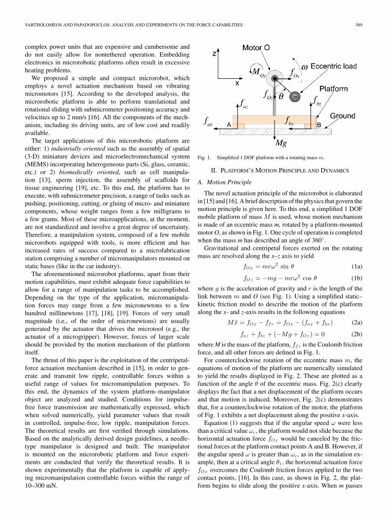
Fig. 1. Simplified 1 DOF platform with a rotating mass m.
II. PLATFORM’S MOTION PRINCIPLE AND DYNAMICS
A. Motion Principle
The novel actuation principle of the microrobot is elaboratedin [15] and [16]. A brief description of the physics that govern themotion principle is given here. To this end, a simplified 1 DOFmobile platform of mass M is used, whose motion mechanismis made of an eccentric mass m, rotated by a platform-mountedmotor O, as shown in Fig. 1. One cycle of operation is completedwhen the mass m has described an angle of 360◦.
Gravitational and centripetal forces exerted on the rotatingmass are resolved along the x–z axis to yield
fOx = mrω2 sin θ (1a)
fOz = −mg − mrω2 cos θ (1b)
where g is the acceleration of gravity and r is the length of thelink between m and O (see Fig. 1). Using a simplified static–kinetic friction model to describe the motion of the platformalong the x- and z-axis results in the following equations
Mx = fOx − ff r = fOx − (fax + fbx) (2a)
faz + fbz + (−Mg + fOz ) = 0 (2b)
where M is the mass of the platform, ff r is the Coulomb frictionforce, and all other forces are defined in Fig. 1.
For counterclockwise rotation of the eccentric mass m, theequations of motion of the platform are numerically simulatedto yield the results displayed in Fig. 2. These are plotted as afunction of the angle θ of the eccentric mass. Fig. 2(c) clearlydisplays the fact that a net displacement of the platform occursand that motion is induced. Moreover, Fig. 2(c) demonstratesthat, for a counterclockwise rotation of the motor, the platformof Fig. 1 exhibits a net displacement along the positive x-axis.
Equation (1) suggests that if the angular speed ω were lessthan a critical value ωc , the platform would not slide because thehorizontal actuation force fOx would be canceled by the fric-tional forces at the platform contact points A and B. However, ifthe angular speed ω is greater than ωc , as in the simulation ex-ample, then at a critical angle θ1 , the horizontal actuation forcefOx overcomes the Coulomb friction forces applied to the twocontact points, [16]. In this case, as shown in Fig. 2, the plat-form begins to slide along the positive x-axis. When m passes
590 IEEE TRANSACTIONS ON ROBOTICS, VOL. 24, NO. 3, JUNE 2008
Fig. 2. Simulation results. (a) Acceleration. (b) Velocity. (c) Position alongthe x-axis as a function of the actuation angle.
Fig. 3. Complete cycle of rotation of the eccentric mass m.
the highest point (at θ = 180◦), friction forces, together withactuation forces, tend to decelerate the platform, and eventually,at an angle θ2 change its direction of motion. As friction still in-creases, reverse motion is decelerated, and finally, the platformis brought to a stop at an angle θ3 . Fig. 3 demonstrates the cycleof rotation of the eccentric mass m and associates the angle θwith the motion state of the platform.
It is observed that the forward motion of the platform takesplace when the rotating eccentric mass m is at the second andthird quadrant of the cycle, i.e., when the vertical reactions arelow, see (1). In contrast to this, the reverse motion takes place inthe third and fourth quadrant, that is, when the vertical reactionsincrease. Therefore, the forward displacement is greater than thereverse one and the resultant displacement per cycle is positive.
It has been shown analytically that the single-dimensionalmotion step that the platform exhibits over a cycle can be madearbitrarily small depending on the actuation speed ω [16].Accordingly, it has been demonstrated that the platform’smotion resolution can reach submicrometer accuracy [15], [16].In general, its resolution is hindered by the limited resolutionof the electronics and by the nonuniform distribution of thecoefficient of friction µ between surface and the contact pointsof the platform.
B. Platform Dynamics
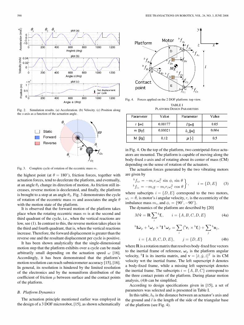
The actuation principle mentioned earlier was employed inthe design of a 3 DOF microrobot, [15], as shown schematically
Fig. 4. Forces applied on the 2 DOF platform: top view.
TABLE IPLATFORM DESIGN PARAMETERS
in Fig. 4. On the top of the platform, two centripetal-force actu-ators are mounted. The platform is capable of moving along thebody-fixed x-axis and of rotating about its center of mass (CM)depending on the sense of rotation of the actuators.
The actuation forces generated by the two vibrating motorsare given by
bfix = −miriω2i sin φi sin θ
bfiz = −mig − miriω2i cos θ
}, i = {D,E} (3)
where subscripts i = {D,E} correspond to the two motors,ωi = θi is motor’s i angular velocity, ri is the eccentricity of theimbalance mass mi , and φi = {90◦,−90◦}.
The dynamics of the platform are described by [20]
M v = R∑
i
bfi , i = {A,B,C,D,E} (4a)
bIωp + bωp × bI bωp =∑
i
(bri × bfi) +∑
j
bnj ,
i = {A,B,C,D,E}, j = {D,E} (4b)
whereR is a rotation matrix that resolves body-fixed free vectorsto the inertial frame of reference, ωp is the platform angularvelocity, bI is its inertia matrix, and v = [x, y, z]T is its CMvelocity wrt the inertial frame. The left superscript b denotesa body-fixed frame, while a missing left superscript denotesthe inertial frame. The subscripts i = {A,B,C} correspond tothe three contact points of the platform. During planar motionanalysis, (4)b can be simplified.
According to design specifications given in [15], a set ofparameters was selected and is presented in Table I.
In this table, h0 is the distance between an actuator’s axis andthe ground and l is the length of the side of the triangular baseof the platform (see Fig. 4).
VARTHOLOMEOS AND PAPADOPOULOS: ANALYSIS AND EXPERIMENTS ON THE FORCE CAPABILITIES 591
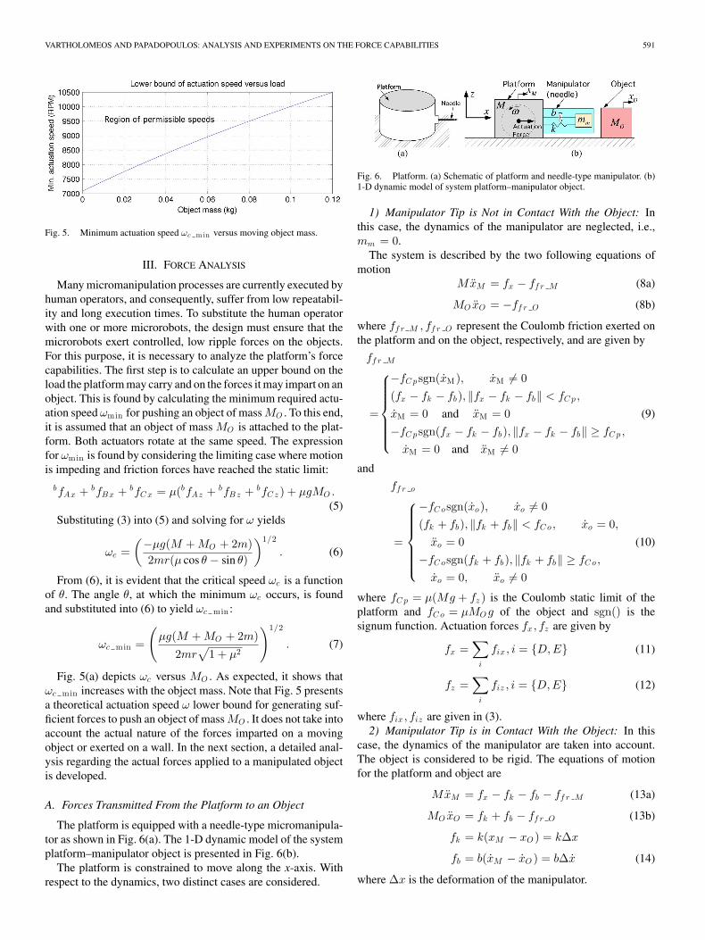
Fig. 5. Minimum actuation speed ωc m in versus moving object mass.
III. FORCE ANALYSIS
Many micromanipulation processes are currently executed byhuman operators, and consequently, suffer from low repeatabil-ity and long execution times. To substitute the human operatorwith one or more microrobots, the design must ensure that themicrorobots exert controlled, low ripple forces on the objects.For this purpose, it is necessary to analyze the platform’s forcecapabilities. The first step is to calculate an upper bound on theload the platform may carry and on the forces it may impart on anobject. This is found by calculating the minimum required actu-ation speed ωmin for pushing an object of mass MO . To this end,it is assumed that an object of mass MO is attached to the plat-form. Both actuators rotate at the same speed. The expressionfor ωmin is found by considering the limiting case where motionis impeding and friction forces have reached the static limit:
bfAx + bfBx + bfC x = µ(bfAz + bfBz + bfC z ) + µgMO .(5)
Substituting (3) into (5) and solving for ω yields
ωc =(−µg(M + MO + 2m)2mr(µ cos θ − sin θ)
)1/2
. (6)
From (6), it is evident that the critical speed ωc is a functionof θ. The angle θ, at which the minimum ωc occurs, is foundand substituted into (6) to yield ωc min :
ωc min =
(µg(M + MO + 2m)
2mr√
1 + µ2
)1/2
. (7)
Fig. 5(a) depicts ωc versus MO . As expected, it shows thatωc min increases with the object mass. Note that Fig. 5 presentsa theoretical actuation speed ω lower bound for generating suf-ficient forces to push an object of mass MO . It does not take intoaccount the actual nature of the forces imparted on a movingobject or exerted on a wall. In the next section, a detailed anal-ysis regarding the actual forces applied to a manipulated objectis developed.
A. Forces Transmitted From the Platform to an Object
The platform is equipped with a needle-type micromanipula-tor as shown in Fig. 6(a). The 1-D dynamic model of the systemplatform–manipulator object is presented in Fig. 6(b).
The platform is constrained to move along the x-axis. Withrespect to the dynamics, two distinct cases are considered.
Fig. 6. Platform. (a) Schematic of platform and needle-type manipulator. (b)1-D dynamic model of system platform–manipulator object.
1) Manipulator Tip is Not in Contact With the Object: Inthis case, the dynamics of the manipulator are neglected, i.e.,mm = 0.
The system is described by the two following equations ofmotion
MxM = fx − ff r M (8a)
MO xO = −ff r O (8b)
where ff r M , ff r O represent the Coulomb friction exerted onthe platform and on the object, respectively, and are given by
ff r M
=
−fC psgn(xM), xM �= 0(fx − fk − fb), ‖fx − fk − fb‖ < fC p,
xM = 0 and xM = 0−fC psgn(fx − fk − fb), ‖fx − fk − fb‖ ≥ fC p ,
xM = 0 and xM �= 0
(9)
and
ff r o
=
−fC osgn(xo), xo �= 0(fk + fb), ‖fk + fb‖ < fC o, xo = 0,
xo = 0−fC osgn(fk + fb), ‖fk + fb‖ ≥ fC o ,
xo = 0, xo �= 0
(10)
where fC p = µ(Mg + fz ) is the Coulomb static limit of theplatform and fC o = µMO g of the object and sgn() is thesignum function. Actuation forces fx, fz are given by
fx =∑
i
fix , i = {D,E} (11)
fz =∑
i
fiz , i = {D,E} (12)
where fix , fiz are given in (3).2) Manipulator Tip is in Contact With the Object: In this
case, the dynamics of the manipulator are taken into account.The object is considered to be rigid. The equations of motionfor the platform and object are
MxM = fx − fk − fb − ff r M (13a)
MO xO = fk + fb − ff r O (13b)
fk = k(xM − xO ) = k∆x
fb = b(xM − xO ) = b∆x (14)
where ∆x is the deformation of the manipulator.
592 IEEE TRANSACTIONS ON ROBOTICS, VOL. 24, NO. 3, JUNE 2008
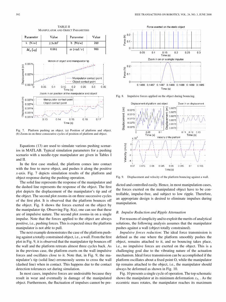
TABLE IIMANIPULATOR AND OBJECT PARAMETERS
Fig. 7. Platform pushing an object. (a) Position of platform and object.(b) Zoom-in on three consecutive cycles of position of platform and object.
Equations (13) are used to simulate various pushing scenar-ios in MATLAB. Typical simulation parameters for a pushingscenario with a needle-type manipulator are given in Tables Iand II.
In the first case studied, the platform comes into contactwith the free to move object, and pushes it along the positivex-axis. Fig. 7 depicts simulation results of the platform andobject response during the pushing operation.
The solid line represents the response of the manipulator andthe dashed line represents the response of the object. The firstplot depicts the displacement of the manipulator’s tip and ofthe object. The second plot zooms-in on three successive cyclesof the first plot. It is observed that the platform bounces offthe object. Fig. 8 shows the forces exerted on the object bythe manipulator tip. Observing Fig. 8(a), one can see that theseare of impulsive nature. The second plot zooms-in on a singleimpulse. Note that the forces applied to the object are alwayspositive, i.e., pushing forces. This is expected since the platformmanipulator is not able to pull.
The next example demonstrates the case of the platform push-ing against a totally constrained object, i.e., a wall. From the firstplot in Fig. 9, it is observed that the manipulator tip bounces offthe wall and the platform retreats almost three cycles back. Asin the previous case, the platform exerts on the wall impulsiveforces and oscillates close to it. Note that, in Fig. 9, the ma-nipulator’s tip (solid line) erroneously seems to cross the wall(dashed line) when in contact. This happens due to the contactdetection tolerances set during simulation.
In most cases, impulsive forces are undesirable because theyresult in wear and eventually in damage of the manipulatedobject. Furthermore, the fluctuation of impulses cannot be pre-
Fig. 8. Impulsive forces applied on the object during bouncing.
Fig. 9. Displacement and velocity of the platform bouncing against a wall.
dicted and controlled easily. Hence, in most manipulation cases,the forces exerted on the manipulated object have to be con-trollable, impulse-free, and subject to low ripple. Therefore,an appropriate design is desired to eliminate impulses duringmanipulation.
B. Impulse Reduction and Ripple Attenuation
For reasons of simplicity and to exploit the merits of analyticalsolutions, the following analysis assumes that the manipulatorpushes against a wall (object totally constrained).
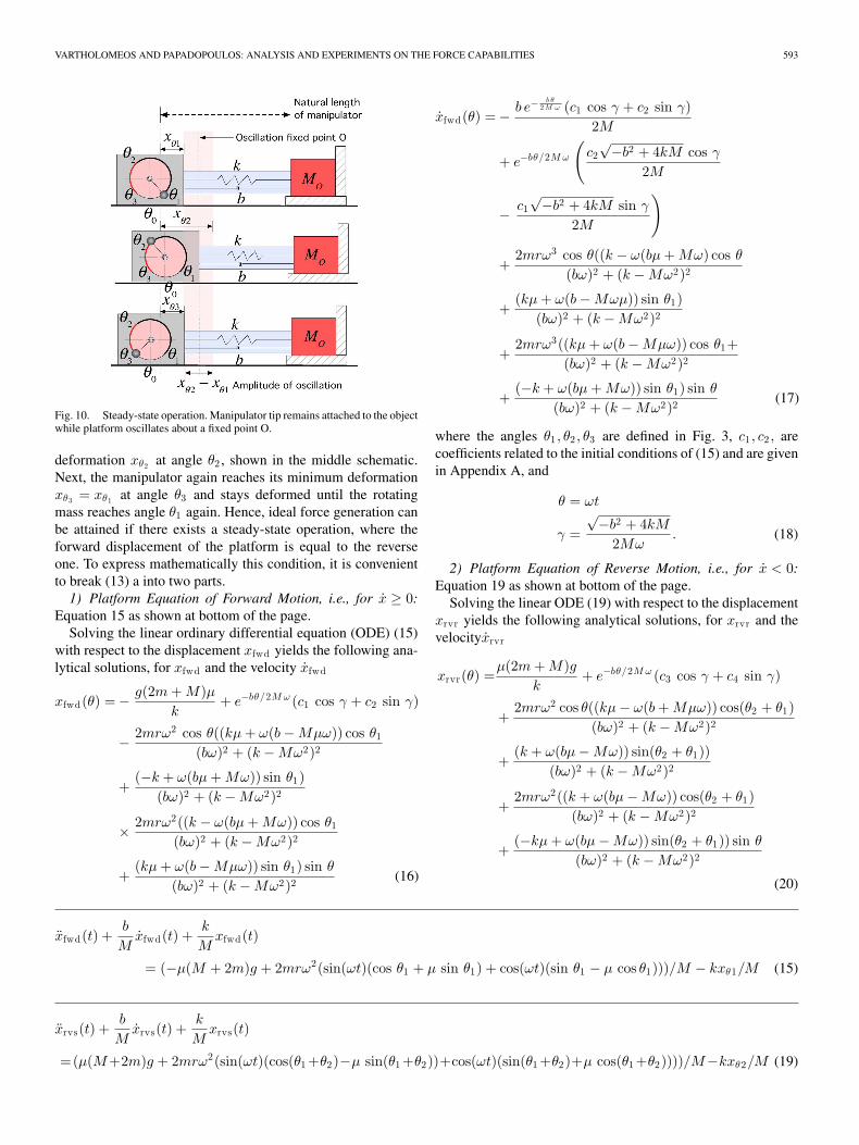
Impulsive forces reduction: The ideal force transmission isdefined as the one where the platform smoothly pushes theobject, remains attached to it, and no bouncing takes place,i.e., no impulsive forces are exerted on the object. This is achallenging goal due to the vibrating nature of the actuationmechanism. Ideal force transmission can be accomplished if theplatform oscillates about a fixed point O, while the manipulatortip remains attached to the object, i.e., the manipulator shouldalways be deformed as shown in Fig. 10.
Fig. 10 presents a single cycle of operation. The top schematicshows the manipulator at its minimum deformation xθ1 . As theeccentric mass rotates, the manipulator reaches its maximum
VARTHOLOMEOS AND PAPADOPOULOS: ANALYSIS AND EXPERIMENTS ON THE FORCE CAPABILITIES 593
Fig. 10. Steady-state operation. Manipulator tip remains attached to the objectwhile platform oscillates about a fixed point O.
deformation xθ2 at angle θ2 , shown in the middle schematic.Next, the manipulator again reaches its minimum deformationxθ3 = xθ1 at angle θ3 and stays deformed until the rotatingmass reaches angle θ1 again. Hence, ideal force generation canbe attained if there exists a steady-state operation, where theforward displacement of the platform is equal to the reverseone. To express mathematically this condition, it is convenientto break (13) a into two parts.
1) Platform Equation of Forward Motion, i.e., for x ≥ 0:Equation 15 as shown at bottom of the page.
Solving the linear ordinary differential equation (ODE) (15)with respect to the displacement xfwd yields the following ana-lytical solutions, for xfwd and the velocity xfwd
xfwd(θ) = − g(2m + M)µk
+ e−bθ/2M ω (c1 cos γ + c2 sin γ)
− 2mrω2 cos θ((kµ + ω(b − Mµω)) cos θ1
(bω)2 + (k − Mω2)2
+(−k + ω(bµ + Mω)) sin θ1)
(bω)2 + (k − Mω2)2
× 2mrω2((k − ω(bµ + Mω)) cos θ1
(bω)2 + (k − Mω2)2
+(kµ + ω(b − Mµω)) sin θ1) sin θ
(bω)2 + (k − Mω2)2 (16)
xfwd(θ) = − b e−b θ
2 M ω (c1 cos γ + c2 sin γ)2M
+ e−bθ/2M ω
(c2√−b2 + 4kM cos γ
2M
− c1√−b2 + 4kM sin γ
2M
)
+2mrω3 cos θ((k − ω(bµ + Mω) cos θ
(bω)2 + (k − Mω2)2
+(kµ + ω(b − Mωµ)) sin θ1)
(bω)2 + (k − Mω2)2
+2mrω3((kµ + ω(b − Mµω)) cos θ1+
(bω)2 + (k − Mω2)2
+(−k + ω(bµ + Mω)) sin θ1) sin θ
(bω)2 + (k − Mω2)2 (17)
where the angles θ1 , θ2 , θ3 are defined in Fig. 3, c1 , c2 , arecoefficients related to the initial conditions of (15) and are givenin Appendix A, and
θ = ωt
γ =√−b2 + 4kM
2Mω. (18)
2) Platform Equation of Reverse Motion, i.e., for x < 0:Equation 19 as shown at bottom of the page.
Solving the linear ODE (19) with respect to the displacementxrvr yields the following analytical solutions, for xrvr and thevelocityxrvr
xrvr(θ) =µ(2m + M)g
k+ e−bθ/2M ω (c3 cos γ + c4 sin γ)
+2mrω2 cos θ((kµ − ω(b + Mµω)) cos(θ2 + θ1)
(bω)2 + (k − Mω2)2
+(k + ω(bµ − Mω)) sin(θ2 + θ1))
(bω)2 + (k − Mω2)2
+2mrω2((k + ω(bµ − Mω)) cos(θ2 + θ1)
(bω)2 + (k − Mω2)2
+(−kµ + ω(bµ − Mω)) sin(θ2 + θ1)) sin θ
(bω)2 + (k − Mω2)2
(20)
xfwd(t) +b
Mxfwd(t) +
k
Mxfwd(t)
= (−µ(M + 2m)g + 2mrω2(sin(ωt)(cos θ1 + µ sin θ1) + cos(ωt)(sin θ1 − µ cos θ1)))/M − kxθ1/M (15)
xrvs(t) +b
Mxrvs(t) +
k
Mxrvs(t)
=(µ(M+2m)g + 2mrω2(sin(ωt)(cos(θ1 +θ2)−µ sin(θ1 +θ2))+cos(ωt)(sin(θ1 +θ2)+µ cos(θ1 +θ2))))/M−kxθ2/M (19)
594 IEEE TRANSACTIONS ON ROBOTICS, VOL. 24, NO. 3, JUNE 2008
xrvr(θ) = − b e−b θ
2 M ω (c3 cos γ + c4 sin γ)2M
+ e−bθ/2M ω
(c4√−b2 + 4kM cos γ
2M
− c3√−b2 + 4kM sin γ
2M
)
+2mrω3 cos θ((k + ω(bµ − Mω)) cos(θ2 + θ1)
(bω)2 + (k − Mω2)2
+(−kµ + ω(b + Mµω)) sin(θ2 + θ1))
(bω)2 + (k − Mω2)2
− 2mrω3((kµ − ω(b + Mµω)) cos(θ2 + θ1)+(bω)2 + (k − Mω2)2
(k + ω(bµ − Mω)) sin(θ2 + θ1)) sin θ
(bω)2 + (k − Mω2)2 (21)
where c3 , c4 are coefficients related to the initial conditions of(19) and are given in Appendix A.
The following mathematical equations should be satisfied forsteady-state operation to occur.
1) The forward displacement must be equal to the reversedisplacement:
xfwd(θ1) = xrvs(θ3). (22)
2) Motion toward the positive x-axis is impeding, i.e., frictionat the contact points has reached its Coulomb level:
2mrω2(sin θ1 − µ cos θ1) = kxfwd(θ1)+µ(M + 2m)g.(23)
3) The maximum displacement during forward motion is de-rived by setting θ = θ2 in (16):
xθ2 = xfwd(θ2). (24)
4) The platform velocity becomes zero when the deforma-tion of the manipulator is equal to xθ2 . This condition isexpressed by setting θ = θ2 in (17):
xfwd(θ2) = 0. (25)
5) The maximum displacement during reverse motion is de-rived by setting θ = θ3 in (20):
xθ3 = xrvs(θ3). (26)
6) The platform velocity becomes zero when the deformationof the manipulator is equal to xθ3 . The condition is derivedby setting θ = θ3 in (21):
xrvs(θ3) = 0. (27)
It is convenient to write (22)–(27) in a functional form:
f1(xθ1 , xθ3) = 0
f2(xθ1 , θθ1) = 0
f3(xθ1 , xθ2 , θθ1 , θθ2) = 0
f4(xθ1 , xθ2 , θθ1 , θθ2) = 0
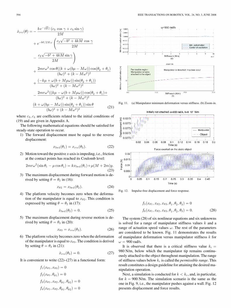
Fig. 11. (a) Manipulator minimum deformation versus stiffness. (b) Zoom-in.
Fig. 12. Impulse-free displacement and force response.
f5(xθ1 , xθ2 , xθ3 , θ1 , θ2 , θ3) = 0
f6(xθ1 , xθ2 , xθ3 , θ1 , θ2 , θ3) = 0. (28)
The system (28) of six nonlinear equations and six unknownsis solved for a range of manipulator stiffness values k and arange of actuation speed values ω. The rest of the parametersare considered to be known. Fig. 11 demonstrates the resultsof manipulator deformation versus manipulator stiffness k forω = 900 rad/s.
It is observed that there is a critical stiffness value kc =980 N/m, below which the manipulator tip remains continu-ously attached to the object throughout manipulation. The rangeof stiffness values below kc is called the permissible range. Thisresult constitutes a design guideline for attaining the desired ma-nipulation operation.
Next, a simulation is conducted for k < kc , and, in particular,for k = 900 N/m. The simulation scenario is the same as theone in Fig. 9, i.e., the manipulator pushes against a wall. Fig. 12presents displacement and force results.
VARTHOLOMEOS AND PAPADOPOULOS: ANALYSIS AND EXPERIMENTS ON THE FORCE CAPABILITIES 595
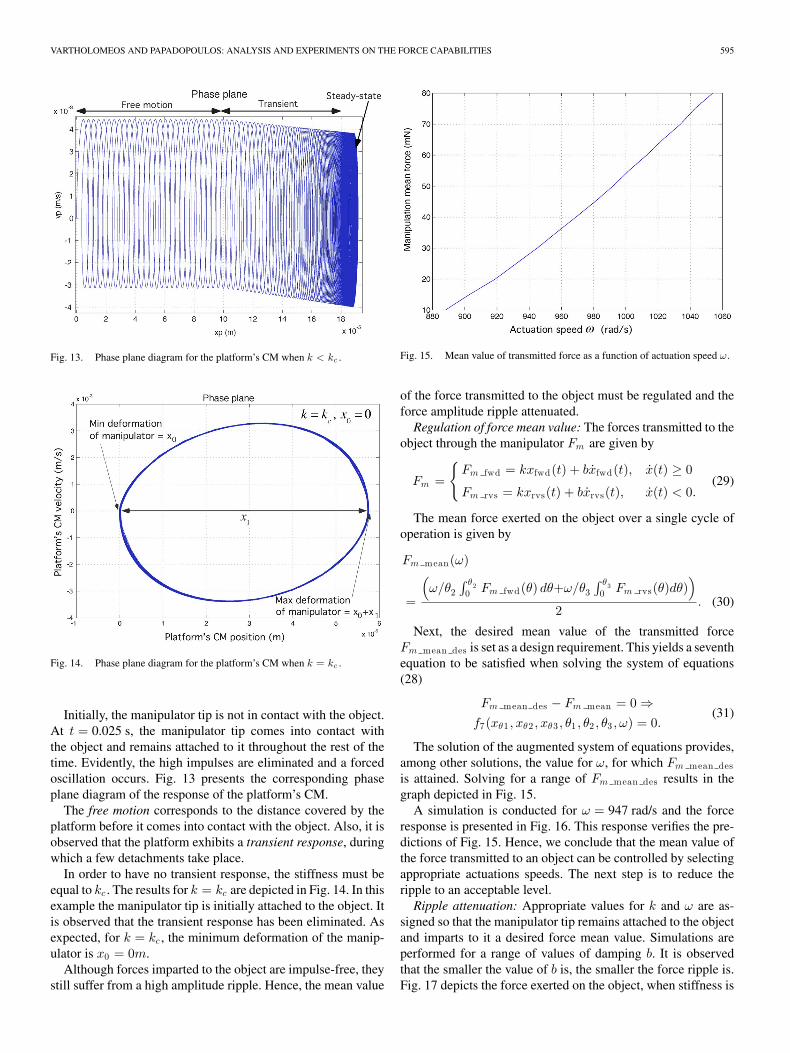
Fig. 13. Phase plane diagram for the platform’s CM when k < kc .
Fig. 14. Phase plane diagram for the platform’s CM when k = kc .
Initially, the manipulator tip is not in contact with the object.At t = 0.025 s, the manipulator tip comes into contact withthe object and remains attached to it throughout the rest of thetime. Evidently, the high impulses are eliminated and a forcedoscillation occurs. Fig. 13 presents the corresponding phaseplane diagram of the response of the platform’s CM.
The free motion corresponds to the distance covered by theplatform before it comes into contact with the object. Also, it isobserved that the platform exhibits a transient response, duringwhich a few detachments take place.
In order to have no transient response, the stiffness must beequal to kc . The results for k = kc are depicted in Fig. 14. In thisexample the manipulator tip is initially attached to the object. Itis observed that the transient response has been eliminated. Asexpected, for k = kc , the minimum deformation of the manip-ulator is x0 = 0m.
Although forces imparted to the object are impulse-free, theystill suffer from a high amplitude ripple. Hence, the mean value
Fig. 15. Mean value of transmitted force as a function of actuation speed ω.
of the force transmitted to the object must be regulated and theforce amplitude ripple attenuated.
Regulation of force mean value: The forces transmitted to theobject through the manipulator Fm are given by
Fm =
{Fm fwd = kxfwd(t) + bxfwd(t), x(t) ≥ 0
Fm rvs = kxrvs(t) + bxrvs(t), x(t) < 0.(29)
The mean force exerted on the object over a single cycle ofoperation is given by
Fm mean(ω)
=
(ω/θ2
∫ θ20 Fm fwd(θ) dθ+ω/θ3
∫ θ30 Fm rvs(θ)dθ)
)2
. (30)
Next, the desired mean value of the transmitted forceFm mean des is set as a design requirement. This yields a seventhequation to be satisfied when solving the system of equations(28)
Fm mean des − Fm mean = 0 ⇒f7(xθ1 , xθ2 , xθ3 , θ1 , θ2 , θ3 , ω) = 0.
(31)
The solution of the augmented system of equations provides,among other solutions, the value for ω, for which Fm mean desis attained. Solving for a range of Fm mean des results in thegraph depicted in Fig. 15.
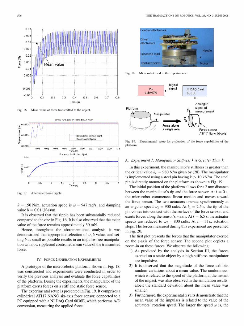
A simulation is conducted for ω = 947 rad/s and the forceresponse is presented in Fig. 16. This response verifies the pre-dictions of Fig. 15. Hence, we conclude that the mean value ofthe force transmitted to an object can be controlled by selectingappropriate actuations speeds. The next step is to reduce theripple to an acceptable level.
Ripple attenuation: Appropriate values for k and ω are as-signed so that the manipulator tip remains attached to the objectand imparts to it a desired force mean value. Simulations areperformed for a range of values of damping b. It is observedthat the smaller the value of b is, the smaller the force ripple is.Fig. 17 depicts the force exerted on the object, when stiffness is
596 IEEE TRANSACTIONS ON ROBOTICS, VOL. 24, NO. 3, JUNE 2008
Fig. 16. Mean value of force transmitted to the object.
Fig. 17. Attenuated force ripple.
k = 150 N/m, actuation speed is ω = 947 rad/s, and dampingvalue b = 0.01 (N·s)/m.
It is observed that the ripple has been substantially reducedcompared to the one in Fig. 16. It is also observed that the meanvalue of the force remains approximately 30 mN.
Hence, throughout the aforementioned analysis, it wasdemonstrated that appropriate selection of ω, k values and set-ting b as small as possible results in an impulse-free manipula-tion with low ripple and controlled mean value of the transmittedforce.
IV. FORCE GENERATION EXPERIMENTS
A prototype of the microrobotic platform, shown in Fig. 18,was constructed and experiments were conducted in order toverify the previous analysis and evaluate the force capabilitiesof the platform. During the experiments, the manipulator of theplatform exerts forces on a stiff and static force sensor.
The experimental setup is presented in Fig. 19. It comprises acylindrical ATI17 NANO six-axis force sensor, connected to aPC equipped with a NI DAQ Card 6036E, which performs A/Dconversion, measuring the applied force.
Fig. 18. Microrobot used in the experiments.
Fig. 19. Experimental setup for evaluation of the force capabilities of theplatform.
A. Experiment 1: Manipulator Stiffness k is Greater Than kc
In this experiment, the manipulator’s stiffness is greater thanthe critical value kc = 980 N/m given by (28). The manipulatoris implemented using a steel pin having k > 10 kN/m. The steelpin is directly mounted on the platform as shown in Fig. 19.
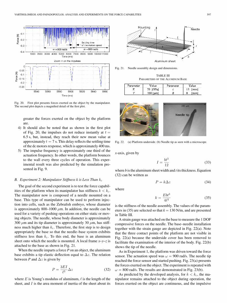
The initial position of the platform allows for a 2 mm distancebetween the manipulator’s tip and the force sensor. At t = 0 s,the microrobot commences linear motion and moves towardthe force sensor. The two actuators operate synchronously atan angular speed ω1 = 900 rad/s. At t1 = 2.5 s, the tip of thepin comes into contact with the surface of the force sensor, andexerts forces along the sensor’s z-axis. At t = 6.5 s, the actuatorspeeds are reduced to ω2 = 800 rad/s. At t = 11 s, actuationstops. The forces measured during this experiment are presentedin Fig. 20.
The first plot presents the forces that the manipulator exertedon the z-axis of the force sensor. The second plot depicts azoom-in on these forces. We observe the following.
1) As predicted by the analysis in Section III, the forcesexerted on a static object by a high stiffness manipulatorare impulsive.
2) It is observed that the magnitude of the force exhibitsrandom variations about a mean value. The randomness,which is related to the speed of the platform at the instantof the impact, was also observed in the simulation results,albeit the standard deviation about the mean value wassmaller.
3) Furthermore, the experimental results demonstrate that themean value of the impulses is related to the value of theactuators’ rotation speed. The larger the speed ω is, the
VARTHOLOMEOS AND PAPADOPOULOS: ANALYSIS AND EXPERIMENTS ON THE FORCE CAPABILITIES 597
Fig. 20. First plot presents forces exerted on the object by the manipulator.The second plot depicts a magnified detail of the first plot.
greater the forces exerted on the object by the platformare.
4) It should also be noted that as shown in the first plotof Fig. 20, the impulses do not reduce instantly at t =6.5 s, but, instead, they reach their new mean value atapproximately t = 7 s. This delay reflects the settling timeof the dc motors response, which is approximately 400 ms.
5) The impulse frequency is approximately one third of theactuation frequency. In other words, the platform bouncesto the wall every three cycles of operation. This exper-imental result was also predicted by the simulation pre-sented in Fig. 9.
B. Experiment 2: Manipulator Stiffness k is Less Than kc
The goal of the second experiment is to test the force capabil-ities of the platform when its manipulator has stiffness k < kc .The manipulator now is composed of a needle mounted on abase. This type of manipulator can be used to perform injec-tion into cells, such as the Zebrafish embryo, whose diameteris approximately 800–1000 µm. In addition, the needle can beused for a variety of pushing operations on either static or mov-ing objects. The needle, whose body diameter is approximately300 µm and its tip diameter is approximately 30 µm, has stiff-ness much higher than kc . Therefore, the first step is to designappropriately the base so that the needle–base system exhibitsstiffness less than kc . To this end, the base is an aluminumsheet onto which the needle is mounted. A local frame x–y–z isattached to the base as shown in Fig. 21.
When the needle imparts a force P on an object, the aluminumbase exhibits a tip elastic deflection equal to ∆z. The relationbetween P and ∆z is given by
P =3EI
�3 ∆z (32)
where E is Young’s modulus of aluminum, � is the length of thesheet, and I is the area moment of inertia of the sheet about its
Fig. 21. Needle assembly design and dimensions.
TABLE IIIPARAMETERS OF THE ALUMINUM BASE
Fig. 22. (a) Platform underside. (b) Needle tip as seen with a microscope.
x-axis, given by
I =bt3
12(33)
where b is the aluminum sheet width and t its thickness. Equation(32) can be written as
P = k∆z (34)
where
k =Ebt3
4�3 (35)
is the stiffness of the needle assembly. The values of the param-eters in (35) are selected so that k = 130 N/m, and are presentedin Table III.
A strain gauge was attached on the base to measure the 1 DOFcompressive forces on the needle. The base–needle installationtogether with the strain gauge are depicted in Fig. 22(a). Notethat the three contact points of the platform are not visible inFig. 22(a) because the underside cover has been removed tofacilitate the examination of the interior of the body. Fig. 22(b)shows the tip of the needle.
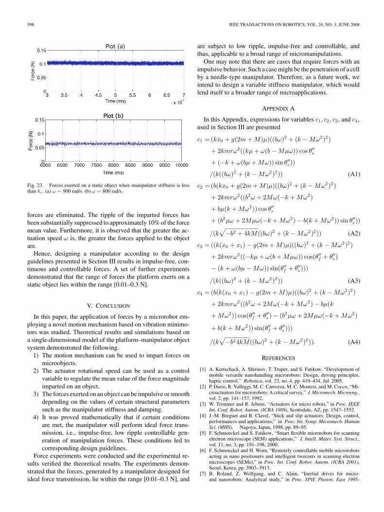
As in Experiment 1, the platform was driven toward the forcesensor. The actuation speed was ω = 900 rad/s. The needle tipreached the force sensor and started pushing. Fig. 23(a) presentsthe forces exerted on the object. The experiment is repeated withω = 800 rad/s. The results are demonstrated in Fig. 23(b).
As predicted by the developed analysis, for k < kc , the ma-nipulator remains attached to the object during operation, theforces exerted on the object are continuous, and the impulsive
598 IEEE TRANSACTIONS ON ROBOTICS, VOL. 24, NO. 3, JUNE 2008
Fig. 23. Forces exerted on a static object when manipulator stiffness is lessthan kc . (a) ω = 900 rad/s. (b) ω = 800 rad/s.
forces are eliminated. The ripple of the imparted forces hasbeen substantially suppressed to approximately 10% of the forcemean value. Furthermore, it is observed that the greater the ac-tuation speed ω is, the greater the forces applied to the objectare.
Hence, designing a manipulator according to the designguidelines presented in Section III results in impulse-free, con-tinuous and controllable forces. A set of further experimentsdemonstrated that the range of forces the platform exerts on astatic object lies within the range [0.01–0.3 N].
V. CONCLUSION
In this paper, the application of forces by a microrobot em-ploying a novel motion mechanism based on vibration minimo-tors was studied. Theoretical results and simulations based ona single-dimensional model of the platform–manipulator objectsystem demonstrated the following.
1) The motion mechanism can be used to impart forces onmicroobjects.
2) The actuator rotational speed can be used as a controlvariable to regulate the mean value of the force magnitudeimparted on an object.
3) The forces exerted on an object can be impulsive or smoothdepending on the values of certain structural parameterssuch as the manipulator stiffness and damping.
4) It was proved mathematically that if certain conditionsare met, the manipulator will perform ideal force trans-mission, i.e., impulse-free, low ripple controllable gen-eration of manipulation forces. These conditions led tocorresponding design guidelines.
Force experiments were conducted and the experimental re-sults verified the theoretical results. The experiments demon-strated that the forces, generated by a manipulator designed forideal force transmission, lie within the range [0.01–0.3 N], and
are subject to low ripple, impulse-free and controllable, andthus, applicable to a broad range of micromanipulations.
One may note that there are cases that require forces with animpulsive behavior. Such a case might be the penetration of a cellby a needle-type manipulator. Therefore, as a future work, weintend to design a variable stiffness manipulator, which wouldlend itself to a broader range of microapplications.
APPENDIX A
In this Appendix, expressions for variables c1 , c2 , c3 , and c4 ,used in Section III are presented
c1 = (kx0 + g(2m + M)µ)((bω)2 + (k − Mω2)2)
+ 2kmrω2((kµ + ω(b − Mµω)) cos θ′′s
+ (−k + ω(bµ + Mω)) sin θ′′s ))
/(k((bω)2 + (k − Mω2)2)) (A1)
c2 = (b(kx0 + g(2m + M)µ)((bω)2 + (k − Mω2)2)
+ 2kmrω2((b2ω + 2Mω(−k + Mω2)
+ bµ(k + Mω2)) cos θ′′s
+ (b2µω + 2Mµω(−k + Mω2) − b(k + Mω2)) sin θ′′s ))
/(k√
−b2 + 4kM((bω)2 + (k − Mω2)2)) (A2)
c3 = ((k(x0 + x1) − g(2m + M)µ)((bω)2 + (k − Mω2)2)
+ 2kmrω2((−kµ + ω(b + Mµω)) cos(θ′′f + θ′′s )
− (k + ω(bµ − Mω)) sin(θ′′f + θ′′s )))
/(k((bω)2 + (k − Mω2)2)) (A3)
c4 = (b(k(x0 + x1) − g(2m + M)µ)((bω)2 + (k − Mω2)2)
+ 2kmrω2((b2ω + 2Mω(−k + Mω2) − bµ(k
+ Mω2)) cos(θ′′f + θ′′s ) − (b2µω + 2Mµω(−k + Mω2)
+ b(k + Mω2)) sin(θ′′f + θ′′s )))
/(k√
−b24kM((bω)2 + (k − Mω2)2)). (A4)
REFERENCES
[1] A. Kortschack, A. Shirinov, T. Truper, and S. Fatikow, “Development ofmobile versatile nanohandling microrobots: Design, driving principles,haptic control,” Robotica, vol. 23, no. 4, pp. 419–434, Jul. 2005.
[2] P. Dario, R. Valleggi, M. C. Carrozza, M. C. Montesi, and M. Cocco, “Mi-croactuators for microrobots: A critical survey,” J. Micromech. Microeng.,vol. 2, pp. 141–157, 1992.
[3] W. Trimmer and R. Jebens, “Actuators for micro robots,” in Proc. IEEEInt. Conf. Robot. Autom. (ICRA 1989), Scottsdale, AZ, pp. 1547–1552.
[4] J.-M. Breguet and R. Clavel, “Stick and slip actuators: Design, control,performances and applications,” in Proc. Int. Symp. Micromech. HumanSci. (MHS). Nagoya, Japan, 1998, pp. 89–95.
[5] F. Schmoeckel and S. Fatikow, “Smart flexible microrobots for scanningelectron microscope (SEM) applications,” J. Intell. Mater. Syst. Struct.,vol. 11, no. 3, pp. 191–198, 2000.
[6] F. Schmoeckel and H. Worn, “Remotely controllable mobile microrobotsacting as nano positioners and intelligent tweezers in scanning electronmicroscopes (SEMs),” in Proc. Int. Conf. Robot. Autom. (ICRA 2001),Seoul, Korea, pp. 3903–3913.
[7] B. Roland, Z. Wolfgang, and C. Alain, “Inertial drives for micro-and nanorobots: Analytical study,” in Proc. SPIE Photon. East 1995:
VARTHOLOMEOS AND PAPADOPOULOS: ANALYSIS AND EXPERIMENTS ON THE FORCE CAPABILITIES 599
Microrobot. Micromech. Syst. Symp., vol. 2593, Bellingham, L. E. Parker,Eds. Philadelphia, PA: SPIE.
[8] C. Alain, Z. Wolfgang, B. Roland, and S. Roland, “A robot system forautomated handling in micro-world,” in Proc. Int. Conf. Intell. RobotsSyst. (IROS 1995), Pittsburgh, PA, 2008, pp. 3185–3191.
[9] S. Martel, M. Sherwood, C. Helm, W. Garcia de Quevedo, T. Fofonoff,R. Dyer, J. Bevilacqua, J. Kaufman, O. Roushdy, and I. Hunter, “Three-legged wireless miniature robots for mass-scale operations at the sub-atomic scale,” in Proc. ICRA 2001, Seoul, Korea, pp. 3423–3428.
[10] S. Martel, “Special surface for power delivery to wireless micro-electro-mechanical systems,” J. Micromech. Microeng., vol. 15, pp. S251–S258,2005.
[11] U. Simu, “Piezoactuators for miniature robots,” Doctoral dissertation,Dept. Mater. Sci., Uppsala Univ., Uppsala, Sweden, 2002.
[12] U. Simu and S. Johansson, “Fabrication of monolithic piezoelectric driveunits for miniature robot,” J. Micromech. Microeng., vol. 12, pp. 582–589,2002.
[13] J. Brufau, M. Puig-Vidal, J. Lopez-Sanchez, J. Samitier, W. Driesen,J. Brequet, N. Snis, S. Urban, S. Johansson, T. Velten, J. Seyfried,R. Estana, and H. Woern, “MICRON: Small autonomous robot for cellmanipulation applications,” in Proc. IEEE ICRA 2004, Barcelona, Spain,pp. 844–849.
[14] P. Vartholomeos, S. Loizou, M. Thiel, K. Kyriakopoulos, andE. Papadopoulos, “Control of the multi agent micro-robotic platformMuiCRoN,” in Proc. 2006 IEEE Int. Conf. Control Appl., TUM, Munich,pp. 1414–1419.
[15] P. Vartholomeos and E. Papadopoulos, “Analysis, design and control ofa planar micro-robot driven by two centripetal-force actuators,” in Proc.IEEE ICRA 2006, Orlando, FL, pp. 649–654.
[16] P. Vartholomeos and E. Papadopoulos, “Dynamics, design and simulationof a novel micro-robotic platform employing vibration micro-actuators,”ASME J. Dyn. Syst., Meas. Control, vol. 128, no. 1, pp. 122–133.
[17] Z. Lu, P. C. Chen, and W. Lin, “Force sensing and control in micromanip-ulation,” IEEE Trans. Syst., Man, Cybern. C, Appl. Rev., vol. 36, no. 6,pp. 713–724, Nov. 2006.
[18] J. J. Gorman and N. G. Dagalakis, “Probe-based micro-scale manipulationand assembly using force feedback,” in Proc. 1st Joint Emerg. Prepared-ness Response/Robot. Remote Syst. Top. Meeting. Salt Lake City, UT,Feb. 11–16, 2006, pp. 621–628.
[19] H. Zhang, Y. Bellouard, E. Burdet, R. Clavel, A. Poo, and W. Hutmacher,“Shape memory alloy microgripper for robotic microassembly of tis-sue engineering scaffolds,” in Proc. IEEE ICRA 2004, Barcelona, Spain,pp. 4918–4923.
[20] L. Sciavicco and B. Siciliano, Modelling and Control of Robot Manipula-tors. New York: Springer-Verlag, 2001.
Panagiotis Vartholomeos (S’04–M’08) received theM.Eng. degree in electrical and electronic engineer-ing from Imperial College London, London, U.K., in2001, and the Ph.D. degree in mechanical engineer-ing from the National Technical University of Athens(NTUA), Athens, Greece, in 2007.
He is currently with the Department of MechanicalEngineering, NTUA. His current research interestsinclude microrobotics, robotics, control and model-ing of dynamic systems.
Dr. Vartholomeos is a member of the TechnicalChamber of Greece (TEE).
Evangelos Papadopoulos (S’83–M’91–SM’97) re-ceived the Diploma in mechanical engineer-ing from the National Technical University ofAthens (NTUA), Athens, Greece, in 1981, andthe M.S. and Ph.D. degrees from MassachusettsInstitute of Technology (MIT), Cambridge, in1983 and 1991, respectively, all in mechanicalengineering.
From 1985 to 1987, he was an Analyst at theHellenic Navy, Athens. In 1991, he joined McGillUniversity and the Centre for Intelligent Machines
(CIM) as an Assistant Professor and was tenured in 1997. He is currently aProfessor in the Department of Mechanical Engineering, NTUA. He is engagedin the areas of systems, controls, mechatronics, and robotics. He is the authoror coauthor more than 150 published technical articles in journals and refer-eed conference proceedings. He is as an Associate Editor of the Machine andMechanism Theory. His current research interests include the area of robotics,modeling and control of dynamic systems, and mechatronics and design.
Dr. Papadopoulos is a Senior Member of the American Institute of Aeronau-tics and Astronautics (AIAA) and a member of the American Society of Me-chanical Engineers (ASME), the Technical Chamber of Greece, and the SigmaXi. He is as an Associate Editor of the IEEE TRANSACTIONS ON ROBOTICS. Hewas a Guest Editor of the IEEE/ASME TRANSACTIONS ON MECHATRONICS.
Related Documents