ANALYSIS AND DESIGN OF HAMMERHEAD BRIDGE PIER USING STRUT AND TIE METHOD. ABDUL KADIR BIN AHYAT UNIVERSITI TEKNOLOGI MALAYSIA

Welcome message from author
This document is posted to help you gain knowledge. Please leave a comment to let me know what you think about it! Share it to your friends and learn new things together.
Transcript

ANALYSIS AND DESIGN OF HAMMERHEAD BRIDGE PIER USING STRUT AND TIE METHOD.
ABDUL KADIR BIN AHYAT
UNIVERSITI TEKNOLOGI MALAYSIA


ANALYSIS AND DESIGN OF HAMMERHEAD BRIDGE PIER
USING A STRUT AND TIE METHOD.
ABDUL KADIR BIN AHYAT
A project report submitted in partial fulfillment of the
requirements for the award of the degree of
Master of Engineering (Civil – Structure)
Faculty of Civil Engineering
Universiti Teknologi Malaysia


DEDICATION
TO MY BELOVED PARENT,
HAJI AHYAT BIN MD. NOR
AND
HAJJAH KAMSIAH BTE BERNEH

ii
ACKNOWLEDGEMENT
In preparing this thesis, I was in contact with many people, researchers, academicians,
and practitioners. They have contributed towards my understanding and thoughts. In
particular, I wish to express my sincere appreciation to my main thesis supervisor,
Associate Professor Ir. Dr. Wahid Omar, for encouragement, guidance, critics and
friendship. I am also very thankful to Mr. Md. Nor, Mr. Jamal from Jurutera Perunding
ZAR for their guidance, advices and motivation. Without their continued support and
interest, this thesis would not have been the same as presented here.
I am also indebted to University Teknologi Malaysia (UTM) for finding my Master
study. Librarians at UTM also deserve special thanks for their assistance in supplying
the relevant literatures.
My sincere appreciation also extends to my friends Ir. Kamaruddin Hassan ( JKR Bridge
Section, Kuala Lumpur), Ir. Che Husni Ahmad (Consultant), Ir. Azli Shah Bin Ali
Bashah (Engineer of Dewan Bandar Raya Kuala Lumpur) and my colleagues who have
provided assistance at various occasions. Thanking to all of you in advanced. I am also
very thankful to Mr. Md. Nor, Mr. Jamal from Jurutera Perunding ZAR who have
provided continued support and assistance in preparing the thesis.
Lastly, I am also deserve special thanks to my beloved wife for her commitment,
encouragement while preparing the works and continued support at various occasions.

iii
ABSTRACT.
The main advantages of truss model are their transparency and adaptability to arbitrary
geometric and loading configuration. In strut-and-tie modeling, the internal stresses are
transferred through a truss mechanism. The tensile ties and compressive struts serve as
truss members connected by nodal zones. The advantages have been thrust into the back
ground by several recent developments of design equations based on truss models,
The present study is focus on developing a uniform design procedure for applying the
strut-and-tie modeling method to hammerhead pier. A study was conducted using
hammerhead piers that were previously designed using the strength method specified by
code. This structure was completed and had put into service. During the inspection,
cracks were observed on the piers. The scope of this study is to highlight the application
of a newer generation strut-and-tie model, which is not practice at the time of the
original design. Depth to span ratios varies from 1.5 to 2.11 and the girders are
transferring loads very close to the support edge, making these hammerheads ideals
candidates for strut-and-tie application. This study only focus on comparison the
reinforcement detail drawing produce previously designed using the strength method,
and reinforcing requirement using strut-and-tie model.
Based on the design studies, a well-defined procedure for designing a hammerhead pier
utilizing the strut-and-tie model was established that may be used by bridge engineers.
There could be numerous reasons for the crack to develop. Shrinkage, stress
concentration or some erection condition may be a few of them.

iv
ABSTRAK.
Kelebihan model “strut and tie ” ia ketelusan melihat kerangka yang di cadangkan dan
memudahkan melihat dan meramalkan kedudukan beban yang dikenakan terhadap
struktur yang di cadangkan.
Analisis mengikut model “strut and tie ” mengunakan kaedah kekuatan mampatan dan
kaedah kekuatan tegangan yang saling bertindak diantara satu sama lain hasil daripada
ikatan disetiap nod. Kebaikan analisis mengunakan kaedah kekuatan mampatan dan
kekuatan tegangan yang saling betindak diantara mereka telah membuat pengkaji cuba
membangunkan kaedah rekabentuk berpandukan kaedah model “strut and tie model”.
Kajian ini menjurus untuk memajukan satu kaedah yang setara untuk merekabentuk
menggunakan kaedah model “strut and tie ” untuk tiang Jambatan berbentuk T. Kajian
ini dikendalikan menggunakan struktur tiang jambatan berbentuk T yang telah
direkabentuk terlebih dahulu menggunakan analisa kekuatan lentur mengikut keperluan
amalan rekabentuk.
Struktur ini telah siap dibina dan dibuka untuk kegunaan lalulintas. Semasa pemerhatian
terhadap struktur tersebut didapati ada beberapa rekahan di permukaan dinding struktur.
Bidang kajian ini adalah untuk menunjukkan penggunaan analisis model “strut and tie
model” yang masih dalam peringkat pembangunan boleh diguna pakai untuk mereka
bentuk struktur tersebut. Nisbah ketinggian dinding tembok dan panjang rasuk adalah
berbeza diantara 1.5 hingga 2.11 dan beban yang terletak diatas rasuk tersebut, hampir
dengan kedudukan tiang rasuk, ini membuatkan struktur tersebut amat sesuai untuk
dianalisis mengunakan kaedah analisis model “strut and tie ”.

v
Hasil daripada kajian rekabentuk ini, satu kaedah rekabentuk mengunakan tindak balas
struktur “strut and tie ” dapat dimajukan untuk dicadangkan untuk merekabentuk
struktur tiang jambatan berbentuk T, yang mana boleh digunakan oleh Jurutera
Jambatan.

vi
TABLE OF CONTENT CHAPTER TITLE PAGE
Title Page i
Declaration ii
Dedication iii
Acknowledgement iv
Abstract v
Abstrak vi
Table of Content viii – xi
List of Tables xii
List of Figure xiii – ivx
List of Symbols xv – xvi
1 INTRODUCTION
1.1 Introduction 1
1.2 Problem Statement 1
1.3 Objective 3
1.4 Scope of Study 3
2 LITERATURE REVIEW
2.1 Introduction 5
2.2 Overview of Strut-and-Tie Model 6
2.3 Adequate Selection of Truss Members 8
2.4 General Strength of Truss Members 12

vii
2.4.1 Strength Requirement 13
2.4.1.1 Rule in Selecting Strut-and-Tie Models 13
2.4.1.2 Strength of Tensile Tie 14
2.4.1.3 Strength of Compressive Strut 14
2.4.1.4 Node Strength 16
2.4.5 Anchorage Requirements (ACI A.4.3) 19
2.4.6 Serviceability Requirement (ACI RA.2.1) 19
2.5 Shear Concerns in Strut-and-Tie Models 20
2.6 AASTHO AND LRFD SPECIFICATION
2.6.1 Introduction 23
2.6.2 AASHTO Standard Code Specification
for the Design of Reinforced Concrete
Member 23
2.6.3 Design for Flexure 25
2.6.4 Design for Shear 28
2.6.5 AASHTO LRFD Standard Code
Specification for the Design of Reinforced
Concrete member using
Strut-and-Tie Model 29
2.6.5.1 Compression Struts 30
2.6.5.2 Tension ties 31
2.6.5.3 Nodal Zones 32
3 METHODOLOGY
3.1 Introduction 34
3.2 Description of Design Procedures 36
3.2.1 The Structure Model 36
3.2.2 Load Generation Procedure 37
3.2.3 Analytical Method 39

viii
3.2.4 Strut-and-Tie Model Truss
Background for Hammerhead Pier 40
3.2.5 Pier Design Procedure 40
3.3 Typical Bridge Hammerhead Pier
Analysis / Design 42
3.3.1 Project Description 42
3.3.2 Original Analysis / Design 42
3.3.3 Strut-and-Tie Analysis / Design 42
3.3.4 Strut-and-Tie Analysis / Design
For Phase 1 44
3.3.5 Strut-and-Tie Analysis / Design
For Phase 2 47
3.3.6 Strut-and-Tie Analysis / Design
For Phase 3 50
3.3.7 Strut-and-Tie Analysis / Design
For Phase 4 53
3.4 Typical Bridge Hammerhead Pier
Design Example 62
3.4.1 Design Example 1 62
3.4.1.1 Steel Reinforcement for Main
Tension ties 62
3.4.1.2 Calculation for Inclined Strut 63
3.4.1.3 Secondary Reinforcement 65
3.4.2 Design Example 2 68
3.4.2.1 Steel Reinforcement for Main
Tension ties 68
3.4.2.2 Calculation for Inclined Strut 69
3.4.2.3 Secondary Reinforcement 71
3.4.3 Design Example 3 74
3.4.3.1 Steel Reinforcement for Main
Tension ties 74

ix
3.4.3.2 Calculation for Inclined Strut 75
3.4.3.3 Secondary Reinforcement 77
4 RESULT AND ANALYSIS
4.1 Introduction 81
4.2 Analysis of Result 81
4.2.1 Possibility of Cracking 82
4.2.2 Phase Construction 82
4.3 Discussion of Results 83
5 DESIGN RECOMMENDATION
5.1 Introduction 84
5.2 Recommendation Strut-and-Tie
Design Procedure For Hammerhead piers 84
5.2.1 Determination of Load 84
5.2.2 Defining the Truss Model 84
5.2.3 Dimensioning of Tensile Ties,
Compressive Struts and Nodal Zones 86
6 SUMMARY AND CONLUSION
6.1 Summary 89
6.2 Conclusions 90
REFERENCES 93

x
LIST OF TABLES.
TABLE NO. TITLE PAGE
3.1 Load Cases Definition 39
3.2 Tabulated estimated Load 43
3.3 Tabulated Member Forces For Each Construction Phases 56

xi
LIST OF FIGURES.
FIGURE NO TITLE PAGE
2.1 B-Region and D-Region 7
2.2 ACI Section 10.7.1 For Deep Beam 8
2.3 Example strut-and-tie model, And acceptable Model 10
and Poor Model
2.4 Basic Type of Strut in a 2-D Member 12
2.5 Basic Type of Strut in a 2-D Member 15
2.6 Illustrates some typical example of singular and smeared 18
nodes.
2.7 Inclined cracking 20
2.8 Truss like action 20
2.9 Analogous truss 20
2.10 Truss analogy 21
2.11 Application of sectional design model and strut-and-tie 21
model for series of beams tested by Kani (1979), adapted
from Collins and Mitchell (1991)
2.12 Rectangular Section with Tension Reinforcement Only. 25
2.13 Rectangular Section with Compression and Tension 26
Reinforcement
3.1 Reinforcing pattern provide by original design 35
3.2 3D structure model 37
3.3 Load case condition 38
3.4 3D strut and tie model 41
3.5 2D strut and tie model 43

xii
3.6 Proposed Load Application for Phase 1 44
3.7 Result of Force in Member 45
3.8 Result member deflected shape 46
3.9 Proposed Load Application for Phase 2 47
3.10 Result of Force in Member 48
3.11 Result member deflected shape 49
3.12 Proposed Load Application for Phase 3 50
3.13 Result of Force in Member 51
3.14 Result member deflected shape 52
3.15 Proposed Load Application for Phase 4 53
3.16 Result of Force in Member 54
3.17 Result member deflected shape 55
3.18 Maximum Members Force 61
3.19 Transverse tension in strut between node N1 and N2 67
3.20 Reinforcing pattern analyses using strut-and-tie-model 80

xiii
LIST OF SYMBOLS
a = depth of the compression block
As = the required area of steel
Ac = cross sectional area at the end of Strut
An = area of a Nodal Zone face in which the force is framing,
measured perpendicular to the direction of the force.
b = width of concrete section
bw = the width of web
d = depth from extreme compression fibres to reinforcing steel
D = depth of the nodal zone
DA = available effective depth
DR = Required effective depth
f’c = concrete compressive strength.
fcu = effective compressive strength and
fy = the tie yield strength
Fi = force in strut or tie i
Fn = nominal strength of Strut, Tie, or Node, and
Fu = factored force demand of the Strut, Tie, or Node.
li = length of member i
Mn = nominal moment capacity
Nu = the factored tie force
Pn = nominal resistance of strut or tie
Pu = ultimate capacity of strut or tie
Vc = the nominal shear strength provided by the concrete
Vn = the factored shear force at the section considered
W = width of the nodal zone

xiv
βs = 1.00 for prismatic Struts in uncracked compression zones,
βs = 0.04 for Struts in tension members,
βs = 0.75 if Struts may be bottle shaped and crack control
reinforcement is included,
βs = 0.60 if Struts may be bottle shaped and crack control
reinforcement is not included, and
βs = 0.60 for all other cases.
βn = 1.00 if Nodes are bounded by Struts and/or bearing areas,
βn = 0.80 if Nodes anchor only one Tie, and
βn = 0.60 if Nodes anchor more than one Tie.
φ = strength reduction factor,
εmi = mean strain of member i
ρvi = steel ratio of the i-th layer of reinforcement crossing that strut
γi = angle between the axis of a strut and the bars

i

CHAPTER 1
INTRODUCTION 1.1 Introduction Strut-and-tie modeling is an analysis and design tool for reinforced concrete
elements in which it may be assumed that internal stresses are transferred through a
truss mechanism. The tensile ties and compressive struts serve as truss members
connected by nodal zones. The internal truss, idealized by the strut-and-tie model,
implicitly account for the distribution of both flexure and shear.
1.2 Problem Statement Three procedure are currently used for the design of load transferred
members such as deep beams:
Empirical design method
Two or three dimensional analysis, either linear or nonlinear
By mean of trusses composed of concrete struts and steel tension ties.
Strut and tie model is considered a rational and consistent basis for designing
cracked reinforced concrete structure. It is mainly applied to the zones where the

2
beam theory does not apply, such as geometrical discontinuities, loading points,
deep beams and corbels.
The main advantage of truss model are their tranparency and adaptability to
arbitrary geomatric and loading configuration. In strut-and-tie modelling, the
internal stresses are tranferred through a truss mechanism. The tensile ties and
compressive struts serve as truss members connected by nodal zones. The
advantages have been thrust into the back ground by several recent developements
of design equations based on truss models,
In 1998, the AASHTO LRFD Bridge Specifications (1998) incorporated the
strut and tie modeling procedure for the analysis and design of deep reinforced
concrete members where sectional design approaches are not valid. In most
instances, hammerhead piers can be defined as deep reinforced concrete members
and therefore, should be designed using the strut-and-tie modeling approach.
However, most bridge engineers do not have a broad knowledge on the strut-and-tie
model due to the unfamiliarity with the design procedure. Therefore, it is likely
that, with the formulation of a well-defined strut-and-tie modeling procedure,
practicing engineers will become more comfortable with the design method and
therefore, employ the method more often and consistently.
The succesful application of a strut-and-tie model depend on a reliable
visualization of the path of the force flows. In a typical strut-and-tie analysis, the
force distribution is visualised as compressive struts and tensiles ties, respectively.

3
1.3 Objectives The specific objectives of the study are:
To ascertain the degree of strut-and-tie modeling implementation.
To compare the flexure and shear reinforcing requirements for typical
hammerhead type bridge piers using both strut-and-tie modeling and standard
sectional design practices, and
To develop a uniform design procedure for employing strut-and-tie
modeling for hammerhead piers.
Most codes of practice use sectional methods for designed of conventional
beams under bending and shear. ACI building Code 318M-95 assumes that flexure
and shear can be handle separately for the worst combination of flexure and shear at
a given section. The interaction between flexure and shear is addressed indirectly by
detailing rules for flexural reinforcement cutoff point.
1.4 Scope of Study In these study pier caps was designed using the strut-and-tie modeling
procedure and the results compared to the results of the sectional design method. By
comparing the results, the reduction or increase in the flexural steel and the shear
steel can be quantified.
These new procedure can provide rational and safe design framework for
structural concrete under combined actions, including the effects of axial load,
bending and torsion.

4
In addition specific checks on the level of concrete stresses in the member are
introduced to ensure sufficient ductile behavior and control of diagonal crack widths
at service load level.

CHAPTER 2
LITERATURE REVIEW 2.1 INTRODUCTION The strut and tie models have been widely used as effective tools for
designing reinforced concrete structures. The idea of a Strut-and-Tie Model came
from the truss analogy method introduced independently by Ritter [1] and Morsch
[2] in the early 1900s for shear design. This method employs so called Truss
Models as its design basis. The model was used to idealised the flow of forced in
a cracked concrete beam. In parallel with the increasing availibility of the
experimental results and the developement of limit analysis in the plastcity
theory, the truss analogy method has been validated and improved considerably in
the form of full member or sectional design procedures. The Truss Model has also
been used as the design basis for torsion.
Later, Schlaich, et al [3] worked to combined individual research
conducted on various reinforced concrete elements in such a fashion that Strut-
and-Tie modeling could be used for entire structure.
Strut-and-Tie modeling is an analysis and design tool for reinforced
concrete elements in which it may be assumed that flexural and shearing stresses
are tranferred internally in a truss type member comprised of concrete
compressive struts and steel reinforcing tension ties. It should be noted that while
the shear design is theoritically couple with the truss model, in most instances

6
designers perform a separate check for providing additional strirrup type shear
reinforcement.
Several theoretical and experimental studies had been carried out to
analyses the phenomenon of the shear failure of reinforced concrete beams.
During the past few years design codes ACI [4] and AASHTO [5] have adopted
Strut-and-tie principles for the design deep beam members. The definition of deep
section provided by these specification classifies most hammerhead piers as deep
beam.
This literature review is conducted to establish the state of knowledge with
regard the possible crack to the hammerhead bridge. The argument has been arise
on theoritical method which are most applicable to this type of structure. Strut-
and-tie modeling is an analysis and design tool for reinforced concrete which are
most suitable for the hammerhead bridge pier but a comparison must be made
with beam theory in order to make a comparison with the actual behaviour of the
structure . A comparison will be made on the analytical model on the design the
hammerhead piers using the strength design method as specified by the standard
specification in order to evaluate strut-and-tie modeling. This study will help to
focus on developing design procedure for applying to hammerhead bridge pier.
2.2 Overview of Strut-and-Tie Modeling
Strut-and-Tie Method (STM) has been used for several years in Europe
and had been included in the AASHTHO LRFD [5] Bridge Specification since
1994, it is a new concept for many structural engineers, recommendation for the
used of STM to design reinforced concrete members were discuss by previous
researchers. In selecting the appropriate design approach, focused on
understanding the internal distribution of forces in a reinforced concrete structure
and have defined two specific regions; B-Regions and D-Regions as shown in
Figure 2.1. The B-Regions of a structure (where B stands for Beam, Bending, or
7
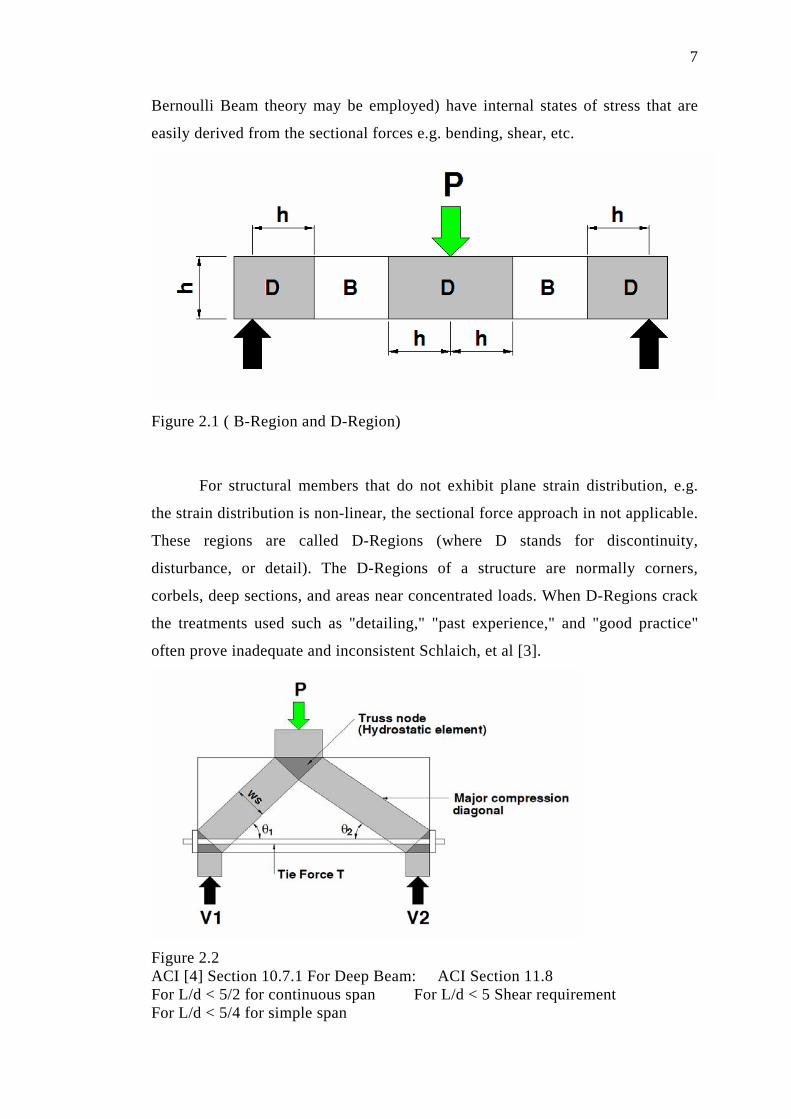
Bernoulli Beam theory may be employed) have internal states of stress that are
easily derived from the sectional forces e.g. bending, shear, etc.
Figure 2.1 ( B-Region and D-Region)
For structural members that do not exhibit plane strain distribution, e.g.
the strain distribution is non-linear, the sectional force approach in not applicable.
These regions are called D-Regions (where D stands for discontinuity,
disturbance, or detail). The D-Regions of a structure are normally corners,
corbels, deep sections, and areas near concentrated loads. When D-Regions crack
the treatments used such as "detailing," "past experience," and "good practice"
often prove inadequate and inconsistent Schlaich, et al [3].
Figure 2.2 ACI [4] Section 10.7.1 For Deep Beam: ACI Section 11.8 For L/d < 5/2 for continuous span For L/d < 5 Shear requirement For L/d < 5/4 for simple span

8
Figure 2.2 provided a simple strut-and-tie model applied to a simply
supported deep beam. In this figure, the lighter shaded region represent concrete
compressive struts, the steel reinforcing bar represent a tensile tie, and the dark
shared regions represent nodal zones.
The tension ties in the truss model may represent one or several layers of
flexural reinforcement in the deep section. The locations of the tension ties
normally are defined at the centroid of reinforcing mat.
2.3 Adequate Selection of Truss Members The successful application of a strut-and-tie model depends on a reliable
visualization of the paths of force flow. In a typical strut-and-tie analysis, the
force distribution is visualized as compressive and tensile force flows that are
modeled as compressive struts and tensile ties.
The engineering judgment and an iterative procedure required to produce
an adequate reinforcement pattern for a given member. The process of defining
the truss begins by defining the flow of forces in the member and locating the
nodal zones at points where the external loads act and the loads are transferred
between structural members, e.g. the pier cap to pier column or at the supports.
The tension ties and compression struts can then be located once the nodal zones
have been defined.
The tension ties are located at the assumed centroid of tensile reinforcing
beginning and terminating at nodal zones. The compression struts are defined to
coincide with the compressive field and, as with the tensile ties, begin and
terminate at the nodal zones.

9
The truss should exhibit equilibrium at each node and should portray an
acceptable truss model. The good model is should be more closely approach to
the elastic stress trajectories. The poor model requires large deformation before
the tie can yield, break the rule that concrete has a limited capacity to sustain
plastic deformation. Figure 2.3 illustrates the difference between an acceptable
model and a poor model.
Figure 2.3 Example strut-and-tie model, An acceptable Model and Poor Model
(This figure cited from lecture note Dr.C.C. Fu, Ph.D, P.E, University of
Maryland)
In a cracked structural concrete member, loads are tranmitted through a set
of commpressive stress fields that are distributed and interconnected by a tensile
stress fields. The flow of compressive stresses can be idealised using compression

10
members called strut, and tension stress fields are idealised using tension member
called ties. Since reinforced ties are much more deformable than concrete struts,
the model with the least and shortest ties should provide the most favorable
model. Schlaich et al., proposes a simple criterion for optimizing a model that
derived from the principle of minimum strain energy for linear elastic behavior of
the struts and ties after cracking. The contribution of the concrete struts can
generally be omitted because the strains of the struts are usually much smaller
than those of the steel ties. An ideal arrangement of ties and strut to minimise
both the forces in the various component element, and the length of the elements.
This is formulated as a design criterion by as follows. Schlaich, et al [3]
n Fili εmi = Minimum
Where
Fi = force in strut or tie i
li = length of member i
εmi = mean strain of member i
Strut-and-Tie Modeling of Structural Concrete by Dr. Quang Quan Liang
at al [6], School of Civil and Enviromental Engineering, The University of New
South Wales, Sydney Australia developed a performance-based strut-and-tie
modeling procedure for reinforced concrete citing the inefficiency of the trial-
and-error iterative process that is based on the designer’s intuition and past
experience. Their optimization procedure consists of eliminating the most lowly
stressed portions from the structural concrete member to find the actual load path.
Liang, et al [6], proposes that minimizing the strain energy is equivalent to
maximizing the overall stiffness of a structure and that the strut-and-tie system
should be based on system performance (overall stiffness) instead of component
performance (compression struts and tension ties).
Related Documents