ANALYSIS AND DESIGN OF BRIDGE SUBSTRUCTURES USING VB.NET A DISSERTATION Submitted in partial fulfillment of the requirements for the award of the degree of MASTER OF TECHNOLOGY in CIVIL ENGINEERING (With Specialization in Computer Aided Design) By AMITKUMAR M. PATEL DEPARTMENT OF CIVIL ENGINEERING INDIAN INSTITUTE OF TECHNOLOGY ROORKEE ROORKEE -247 667 (INDIA) JUNE, 2008

Welcome message from author
This document is posted to help you gain knowledge. Please leave a comment to let me know what you think about it! Share it to your friends and learn new things together.
Transcript
ANALYSIS AND DESIGN OF BRIDGE SUBSTRUCTURES USING VB.NET
A DISSERTATION
Submitted in partial fulfillment of the requirements for the award of the degree
of MASTER OF TECHNOLOGY
in CIVIL ENGINEERING
(With Specialization in Computer Aided Design)
By
AMITKUMAR M. PATEL
DEPARTMENT OF CIVIL ENGINEERING INDIAN INSTITUTE OF TECHNOLOGY ROORKEE
ROORKEE -247 667 (INDIA) JUNE, 2008

CANDIDATE'S DECLARATION
I hereby declare that the work which is being presented in this thesis report
entitled "ANALYSIS AND DESIGN OF BRIDGE SUBSTRUCTURES USING VB.NET " in partial fulfillment of the requirement for the award of the degree of the
Master of Technology with specialization in Computer Aided Design in the Department
of Civil Engineering, Indian Institute of Technology Roorkee, is an authentic record of
my own work carried out during past one year from July 2007 to June 2008, under the
supervision of Dr. Bhupinder Singh, Assistant professor, Department of Civil
Engineering, Indian Institute of Technology Roorkee.
The matter presented in this thesis has not been submitted by me for the award of
any other degree of this or any other Institute.
(Am? u. Patel)
Date: 30"' June, 2008,
Place: IIT Roorkee
This is to certify that the above statement made by the candidate is correct to the
best of my knowledge.
Date (BI upind Sin - cqb$
Asst. Professor,
Dept. of Civil Engg.,
IIT Roorkee,
Roorkee-247667(India)

ACKNOWLEDGEMENT
I wish to express my deep regards and sincere gratitude to my supervisor Dr. Bhupinder Singh, Assistant Professor, Department of Civil Engineering, IIT Roorkee, Roorkee, for his expert guidance, valuable suggestions and encouragement at
all stages of the present study. .4
I am thankful to Dr. G. Ramasamy, Professor, Department of Civil Engineering,
IIT Roorkee, Roorkee, for his valuable guidance and advice at the different stages of the present study.
I also acknowledge the blessings of my family members and co-operation of my friends, which is very valuable to me.
Amit umarM.Patel M.TECH (II"d Year),
Computer Aided Design, Department of Civil Engineering,
IIT Roorkee.
Date: 30-06-2008 Place: Roorkee
ABSTRACT
The analysis and design of all the components of even the most simple bridge
type can be a fairly laborious and cumbersome job especially with respect to the various elements of the bridge substructure. For bridges located on major perennial rivers, resort will have to be made to deep foundations like wells or pile foundations, the design of which involves lengthy computational effort. The bridge engineer should be equipped with a handy computational tool with the help of which he can quickly and reliably determine the suitability of various layouts and configuration of the sub-structure before
finalizing the most optimum design of the substructure. In this thesis and attempt has been made to develop a P.C. based software on VB.Net platform for the analysis and
design of substructure for bridges with simply-supported spans. The computer programme includes the analysis and of wall-type and circular piers and includes the option for the complete analysis and design of two-types of deep foundations on the basis of the relevant IS Codes of Practice: Well foundations and pile foundations. The pile foundations can be analyzed and designed for both river and non-river bridge crossings and the user is presented the option of two types of piles for use in the foundations:
under-reamed piles particularly for non-rivet bridge foundations and bored cast-in-situ
circular piles. A noteworthy feature of the program is that lateral load analysis of both free and fixed-head piles can be carried out by the user in line with the recommendations of the relevant IS Codes. The user friendly and interactive program assists the user in the selection of preliminary dimensions of the well foundation, the safety of which is checked of the elastic state of the soil surrounding the well and at ultimate loads. Structural design of the critical well components like well curb, steining and well cap is
incorporated in the software. The results for foundation design obtained from the
program have been validated with long-hand calculations present in the Appendix.
CONTENTS
Chapter No. Title Pg. No. Chapter-I INTRODUCTION
1.1 Introduction 1 1.2 Objective of the Thesis 3 1.3 Scope of the Work 3
1.4 Organization of the Thesis 3
Chapter-2 PIERS & PIER CAPS
2.1 Introduction 4
2.2 Types of Piers 4 2.3 Procedure for Analysis of Pier 6
2.4 Conclusions 9
Chapter-3 WELL FOUNDATIONS 3.1 Introduction 10
3.2 Types of Well Foundations 10
3.3 Elements of a Well Foundation 12
3.4 Analysis and Design of Well Foundation 14
3.4.1 Determination of Maximum Scour Depth 14
3.4.2 Loads for Well Foundation Design 16
3.4.3 Stability Analysis of Well Foundations 16
3.4.4 Design of Well Curb 21 3.4.5 Design of Well Steining 22
3.4.6 Design of Bottom Plug 23
3.4.7 Design of Well Cap 23
3.5 Conclusions 25
Chapter-4 PILE FOUNDATIONS 4.1 Introduction 26
4.2 Design of Pile Foundations 29
4.2.1 Under-reamed Piles 29
4.2.2 Bored Cast-in-situ Piles 30
4.2.3 Numbers, Spacing and Arrangement of Piles 35
4.2.4 Safe Bearing Capacity of Pile Groups 37
Distribution of load between Vertical Piles of 4.2.5 39
Pile Group
4.2.6 Lateral load analysis of Piles 40
4.2.7 Structural Design of Pile 42
4.2.8 Settlement of Pile Group 44
4.2.9 Design of Pile Cap 46
4.3 Conclusions 48
Chapter-5 SOFTWARE FEATURES
5.1 Introduction 49
5.2 Functions Layout of the Software 49
Selection and Input of Parameters used for 5.2.1 50
Analysis and Design of Foundations
5.2.2 Analysis of Pier 53
Estimation of Scour Depth for Foundation 5.2.3 53
Design
5.2.4 Analysis and Design of Well Foundation 55
5.2.5 Analysis and Design of Pile Foundation 62
5.3. Conclusions. 73
Chapter-6 RESULTS AND DISCUSSION
6.1 Introduction 74
6.2 Problem on Well Foundation 74
6.3 Problem on Pile Foundation 103
6.4 Conclusions 128
Chapter-7 CONCLUSIONS
7.1 Conclusions 129
7.2 Scope for Further Work 129
Chapter-8 REFERENCES 130
SUPPORTING LONG HAND CALCULATIONS FOR THE APPENDIX A 132
ILLUSTRATIVE PROBLEM ON WELL FOUNDATION
APPENDIX B SUPPORTING LONG HAND CALCULATIONS FOR THE ILLUSTRATIVE PROBLEM ON PILE FOUNDATION 164
LIST OF TABLES
Table. Title Pg.No.
No. 2.1 Value of constant K for Pressure Intensity due to Water Current 7
2.2 Permissible Stresses in Concrete 9
3.1 Silt factors for Sandy beds, IRC: 78-20008 15
3.2 Values of the constant Q for square or rectangular wells 20
4.1 Bearing Capacity Factor, JV y 33
4.2 Value of coefficient of horizontal soil stress (KS) 33
4.3 Safe loads for under-reamed piles 35
4.4 Values of the constant r7„ (kN/m3) 41
4.5 Values of the constant K (kN/m2) 41
A-1 Calculation of Maximum Shear forces bearings 141
A-2 Stresses due to horizontal shear force at bearings 141.
A-3 Summary of Stresses due to various forces acting on the Pier 142
A-4 Resultant Compressive Stresses at Point "A" & "B" on Pier 143
A-5 Resultant Tensile Stresses at Point "A" & B" on Pier 143
A-6 Horizontal shear force at bearings & moments at the base of foundation 148
A-7 Seismic moment due of mass of bridge components & Live load, 148
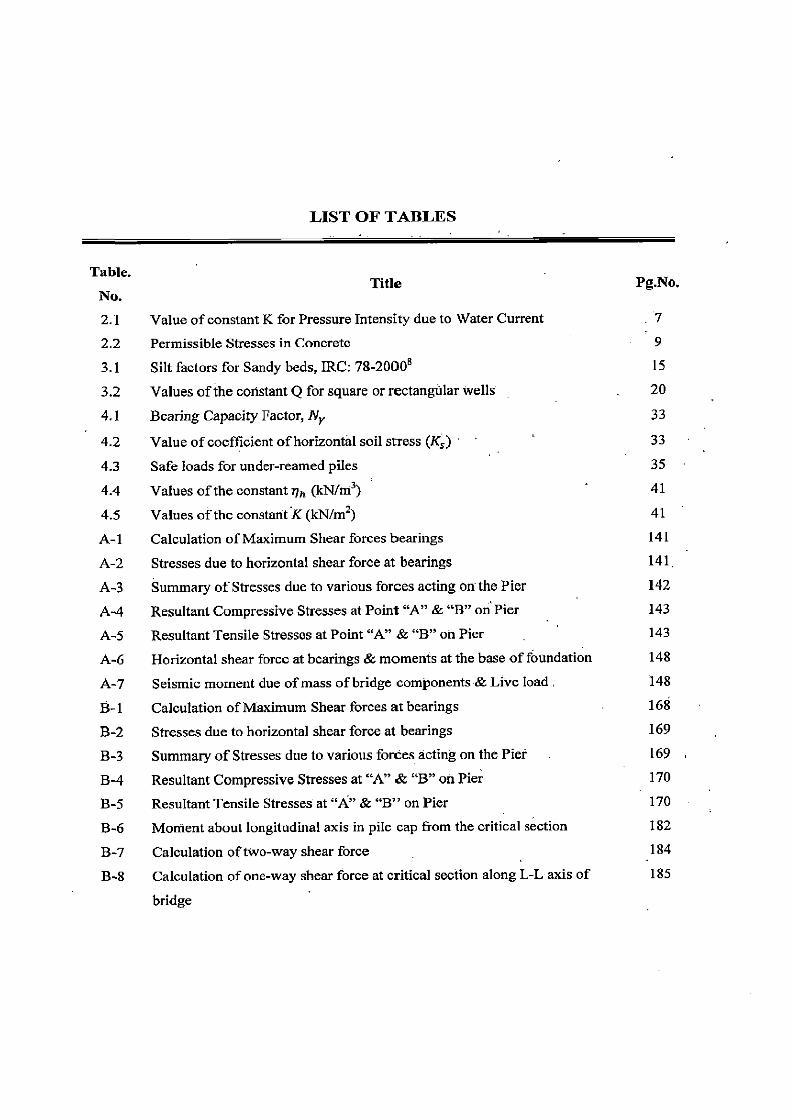
B-1 Calculation of Maximum Shear forces at bearings 168
B-2 Stresses due to horizontal shear force at bearings 169
B-3 Summary of Stresses due to various forces acting on the Net 169
B-4 Resultant Compressive Stresses at "A" & B" on Pier 170
B-5 Resultant Tensile Stresses at "A" & B" on Pier 170
B-6 Moment about longitudinal axis in pile cap from the critical section 182
B-7 Calculation of two-way shear force 184
B-8 Calculation of one-way shear force at critical section along L-L axis of 185
bridge
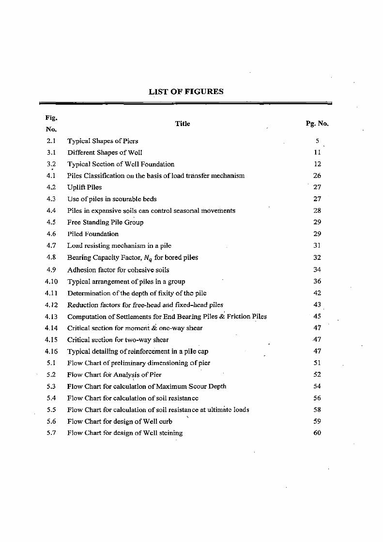
LIST OF FIGURES
Fig, Title Pg. No.
No. 2.1 Typical Shapes of Piers 5
3.1 Different Shapes of Well 11
3.2 Typical Section of Well Foundation 12 4.1 Piles Classification on the basis of load transfer mechanism 26 4.2 Uplift Piles 27 4.3 Use of piles in scourable beds 27 4.4 Piles in expansive soils can control seasonal movements 28
4.5 Free Standing Pile Group 29 4.6 Piled Foundation 29 4.7 Load resisting mechanism in a pile 31
4.8 Bearing Capacity Factor, Nq for bored piles 32
4.9 Adhesion factor for cohesive soils 34
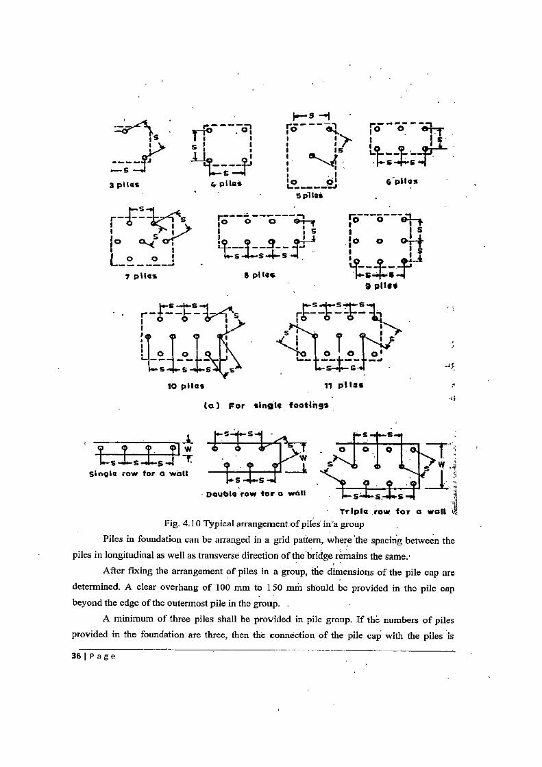
4.10 Typical arrangement of piles in a group 36
4.11 Determination of the depth of fixity of the pile 42
4.12 Reduction factors for free-head and fixed-head piles 43
4.13 Computation of Settlements for End Bearing Piles & Friction Piles 45 4.14 Critical section for moment & one-way shear 47
4.15 Critical section for two-way shear 47
4.16 Typical detailing of reinforcement in a pile cap 47 5.1 Flow Chart of preliminary dimensioning of pier 51
5.2 Flow Chart for Analysis of Pier 52
5.3 Flow Chart for calculation of Maximum Scour Depth 54
5.4 Flow Chart for calculation of soil resistance 56 5.5 Flow Chart for calculation of soil resistance at ultimate loads 58
5.6 Flow Chart for design of Well curb 59 5.7 Flow Chart for design of Well steining 60

5.8 Flow Chart for design of Well Cap 61 5.9 Flow Chart for soil details 63
5.10 Flow Chart for calculating safe bearing Capacity of bored cast-in-situ pile 65 5.11 Flow Chart for calculating safe bearing Capacity of an under-reamed Pile 66 5.12 Flow Chart for calculation of SBC of group of bored cast-in-situ piles 68 5.13 Flow Chart for calculation of SBC of group of under-reamed piles 69 5.14 Lateral load capacity of Under-reamed Pile 70 5.15 Lateral load capacity of Bored Cast-in-situ pile 71 5.16 Design of Pile Cap 72 6.1 Details of Soil layers in Ground 104 A-1 Pier Section in longitudinal direction of bridge 133 A-2 Water Pressure Details 137 A-3 Location of "A" & `B" on pier 142 A-4 Diagram of a Well Foundation 145 A-5 Diagram of Well curb 146 A-6 Diagram of Bottom Plug 146 A-7 Load dispersion area in well cap 158
A-8 Moments in well-cap when freely supported 160 A-9 Moments in well-cap when fully clamped 161 A-10 Reinforcement Details of Well Cap 163 B-1 Pier Section in transverse direction of bridge 164
B-2 Location of "A" & `B" on Pier 170 B-3 Effective overburden pressure on pile 172 B-4 Arrangement of Piles in Foundation 174
B-5 Settlement of End bearing piles 180 B-6 Reinforcement details of Pile Cap 186
CHAPTER 1
INTRODUCTION 1.1 INTRODUCTION
Thomas B. Macaulay once said: "Of all inventions, the alphabet and the printing press alone, excepted, those inventions which abridge distance have done the most for the civilization of our species". Since ancient times, bridges have been the most visible testimony,
to the contribution of engineers. Bridges have always figured prominently in human history. They enhance the vitalities of the cities and aid the social, cultural and economic
improvements of the locations around them. Bridge is a structure providing passage over an obstacle without closing the way
beneath. The required passage may be for a road, a railway, pedestrians, a canal or a pipeline
and the obstacle to be crossed may be a river, a road, railways or a valley. The portion of the
bridge structure below the level of the bearing and above the ,founding level is generally
referred to as the substructure. The design of bridge substructure is an important part of the
overall design for a bridge and affects to a considerable extent the aesthetics, the safety and
the economy of the bridge. Bridge substructure are a very important part of a bridge as it
safely transfers the loads from the superstructure to the earth in such a uranner that the
stresses on the soil are not excessive & the resulting deformations are within the acceptable
limits. The selection of the foundation system for a particular site depends on many
considerations, including the nature of subsoil, location where a bridge is proposed to be
constructed i.e. over a river, road, or a valley, etc. & the scour depth. A bridge may have
either have the following types of foundations:
1. Well foundations: It is the most common type of foundation in India for both road &
railway bridges. Such foundation can be sunk to great depths and can carry very heavy vertical and lateral loads. Well foundations can also be installed in'a boulder stratum. It is a
massive structure and is relatively rigid in its structural behavior.
2. Pile foundations: It consist of relatively long and slender members, called piles which are
used to transfer loads through weak soil or water to deeper soil or rock "strata having'a high
bearing capacity. They are also used in normal ground conditions for elevated road ways.
The analysis and the design of all the components of a bridge particularly with reference to the bridge substructure can become a very lengthy and laborious task if the
calculations are attempted manually. A design engineer would like to try various
liPage --
configurations, shapes and sizes of the principal components of a bridge before finalizing the most optimum combination on the basis of safety, economics and aesthetics of the elements of the super-structure and the sub-structure. At the same time, in spite of the best efforts
during sub-soil investigations, many uncertainties always exist with respect to the sub-soil conditions which may be encountered at pier and foundation locations. Unexpected sub-soil
conditions may require a significant redesign of the foundation or in extreme cases the foundation type may have to be changed from for example an open-footing to a pile or a well foundation. For the above eventualities, it is desirable that a quick, handy and reliable
computational tool should be available to the design engineer for the analyses and design of bridge sub-structure in general and well and pile foundations in particular.
In this thesis an attempt has been made to develop P.C. software package in the
VB.Net platform for the analysis and design of sub-structures for concrete bridges with
simply supported spans. Analysis of the super-structure for loads transferred to the sub-structure is included in
the software. Two IRC loading categories: Class AA and Class A are considered for super-
structure analysis. The option for single lane and two lanes of traffic is included. The user is
provided with the option of two types of concrete piers: wall-type and hammer-head type
with a circular shaft. The analysis and design of both these types of piers is included in the
software. In the software, the option is provided for two types of deep foundations: well and
piles. Well foundations are essentially meant for river-bridge crossings where as the option for pile foundations take care of pile analysis and design for both non-river and river bridge
crossings. The analysis of the well foundation is carried out as per the relevant IRC code for
the resultant axial, lateral loads and moments transferred from the super-structure for the
following two conditions: (1) The soil surrounding the well is in an elastic state (2) At
ultimate load conditions. The program includes check on thickness of the bottom plug and the
analysis and design of the critical components of a well viz, well curb, well steining and well
cap. Practical considerations related to construction of wells are examined through a check on
the sinking effort developed in the well. Two types of piles are available for design of pile
foundations: (1) Under-reamed piles and (2) Bored cast-in-situ circular piles. Under-reamed
piles are essentially meant for non-river bridge crossings and their design for vertical and
lateral loads has been carried out as per recommendations of IS: 2911. The software includes
the analysis and design of both free-head and fixed-head bored cast-in-situ circular piles in cohesion less as well as cohesive soils. A noteworthy feature of the software is the lateral
load analysis of the pile as per the relevant IS Code. The design of the pile foundation
2( Page
concludes with check on group behavior including settlement analysis and structural design of the pile and the pile cap. 1.2 OBJECTIVE OF THE THESIS
Development of an interactive user-friendly software for the analysis and design of substructures of RCC bridges with simply supported spans for river as Well as non-river bridge crossings. 1.3 SCOPE OF THE WORK
The analysis of the simply supported super-structure his been carried out for 'only two loading classes: Class AA and Class A. Two type of piers are included in the software:'wall-type and hammer-head type with a circular shaft. Besides gravity loads, lateral loads due to wind, earthquake and hydro-dynamic effect are considered in the analysis. The well' foundation analysis is performed at both elastic and ultimate state. The analysis and design of pile foundation- is restricted to under-reamed and bored cast-in-situ piles in both cohesibnless` and cohesive soils for vertical as well as lateral loads: Stnictural design of piles and pile-cap is included in the software. The software does not have the option of generating detailing and working drawings of the bridge sub-structure. 1.4 ORGANIZATION OF THE THESIS
• The introduction to the thesis & the scope of present work together with the' organization of thesis is contained in Chapter 1.
• Chapter 2 discusses about the piers in substructure It' contains the details '& summarizes the available literature on pier. The 'steps for analysis for pier' are explained in this chapter.
• The knowledge base of well foundation is provided in Cfiapte'r 3, following the procedure for analysis of well foundation & design of various conrpoinents 6f the well. '
• Chapter 4 includes the literature review on pile foundations At discusses the analysis
& design steps of pile foundations.
• The features & limitations of the software developed es the part of thesis woik are being explained in Chapter 5. The functioning of various modules of the softivare are explained in the form of flow chart, in the same chapter. '
• The application of the proposed software to the analysis & design of typical well foundation and pile foundation is presented in Chapter 6.
• The conclusions from the present study are discussed in Chapter 7. • References form the last part of this thesis.
3IPage
CHAPTER 2
PIERS & PIER CAPS 2.1 INTRODUCTION
Piers are substructures located at the ends of bridge spans at intermediate points
between the abutments. The function of the piers is two-fold: to transfer the superstructure vertical loads to the foundation and to resist all horizontal and transverse forces acting on the
bridge. Piers are generally constructed of masonry or reinforced concrete. Being one of the
most visible components of a bridge, the piers contribute to the aesthetic appearance of the
structure.. They are found in different shapes, depending on the type, size and'dimensions of the superstructure and also on the environment in which the pier is located.
The pier cap (also known as the bridge seat) is the block resting over the top of the pier or the abutment. It provides the immediate bearing surface for the support of the
superstructure at the pier location, and disperses the strip loads from the bearings to the
substructure more evenly. The pier cap is given an offset of 75 mm beyond the edge of the
pier. This offset prevents rain water from dripping down the sides and ends of the pier and also improves the appearance of the pier. Minimum thickriess provided to the pier cap is 225
mm for spans of up to 25 m, otherwise 300 mm.
2.2 TYPES OF PIERS
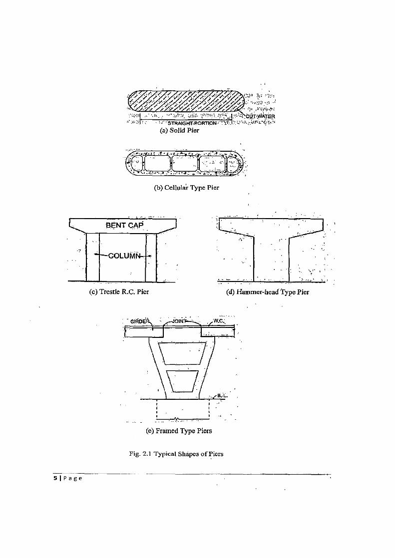
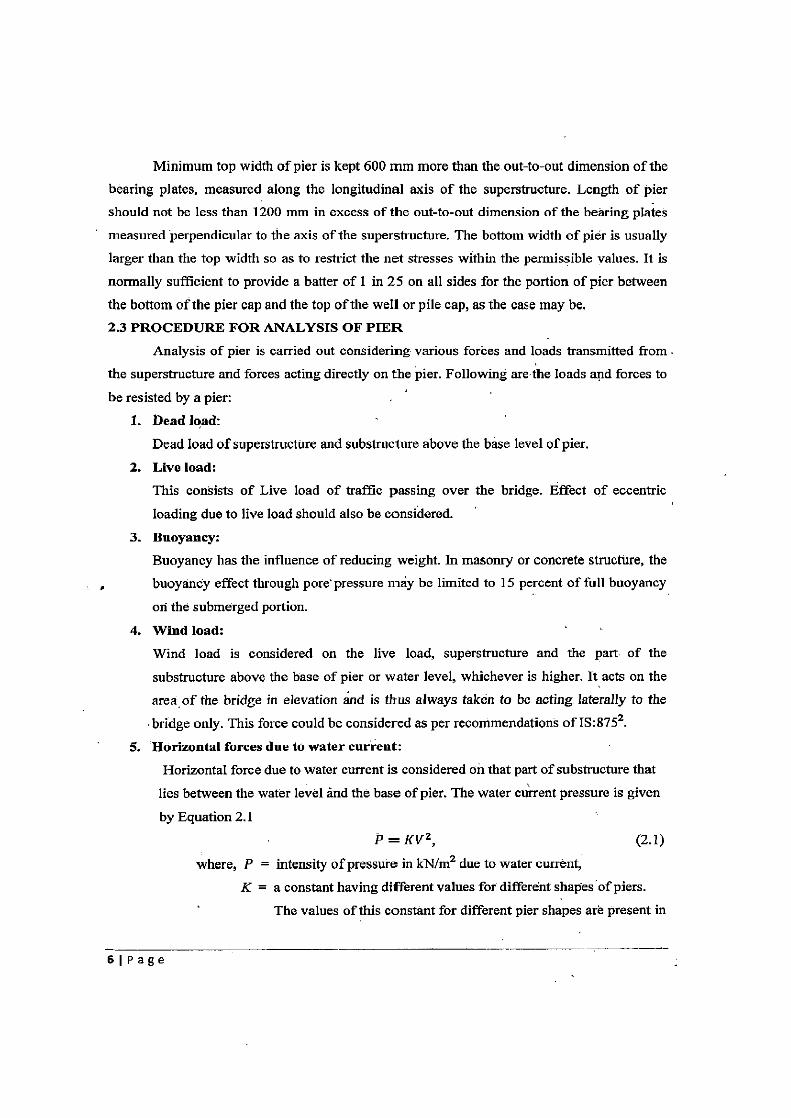
Typical shapes of piers commonly used in practice are as shown in Fig. 2.1. They can
be solid, cellular, trestle or hammer-head types. Solid and cellular piers for river bridges are
provided with semicircular cut-waters to facilitate and streamlined flow and to reduce the
scour. Solid piers can be of.mass concrete or of masonry for heights of up to 6 m and spans
up to about 20 m. Hammer-head type piers are increasingly used in urban elevated highway
applications, as it provides slender substructure with open and free-flowing perception to the
motorists using the road below. It is also used for river crossings with skew alignment, which
will result in least obstruction to passage of flood below the bridge. Cellular, trestle, hammer-
head types are suitable for heights above 6 m and spans over 20 m. In trestle type piers,
concrete hinges have been recently introduced between the top of column and the bent cap in
order to avoid moment being transferred from deck to the columns. Reinforced concrete framed types of piers as shown in Fig. 2.1 (e) have also been used in recent years. Such piers
lead to economy in cost of superstructure as it reduces the span length of girders on either
side of pier, but at the same time it will accumulate debris and floating trees from the stream
flow. Two expansion joints formed on each pier will result in riding discomfort.
4 I Page — --
t%v&~; -Z .CUT~WATER lr .. .:' STAIGH1:PORTION th U'<:%• z` -'
(a) Solid Pier
(b) Cellular Type Pier
Ii
BENT CAP ~I
(c) Trestle R.C. Pier (d) Hammer-head Type Pier
r
NV_:jj a a
~ a
(e) Framed Type Piers
Fig. 2.1 Typical Shapes of Piers
SiPage
Minimum top width of pier is kept 600 mm more than the out-to-out dimension of the
bearing plates, measured along the longitudinal axis of the superstructure. Length of pier should not be less than 1200 mm in excess of the out-to-out dimension of the bearing plates
measuredperpendicular to the axis of the superstructure. The bottom width of pier is usually
larger than the top width so as to restrict the net stresses within the permissible values. It is
normally sufficient to provide a batter of I in 25 on all sides for the portion of pier between
the bottom of the pier cap and the top of the well or pile cap, as the case may be. 2.3 PROCEDURE FOR ANALYSIS OF PIER
Analysis of pier is carried out considering various forces and loads transmitted from.
the superstructure and forces acting directly on the pier. Following are-the loads and forces to
be resisted by a pier:
1. Dead load:
Dead load of superstructure and substructure above the base level of pier.
2. Live load:
This consists of Live load of traffic passing over the bridge. Effect of eccentric
loading due to live load should also be considered.
3. Buoyancy:
Buoyancy has the influence of reducing weight. In masonry or concrete structure, the
buoyancy effect through pore'pressure may be limited to 15 percent of full buoyancy
on the submerged portion.
4. Wind load:
Wind load is considered on the live load, superstructure and the part of the
substructure above the base of pier or water level, whichever is higher. It acts on the
area. of the bridge in elevation and is thus always taken to be acting laterally to the
bridge only. This force could be considered as per recommendations of IS:8752.
5. Horizontal forces due to water current:
Horizontal force due to water current is considered on that part of substructure that
lies between the water level and the base of pier. The water current pressure is given
by Equation 2.1
P=KV 2 , (2.1)
where, P = intensity of pressure in kN/m2 due to water current,
K = a constant having different values for different shapes 'of piers.
The values of this constant for different pier shapes are present in
6I Page
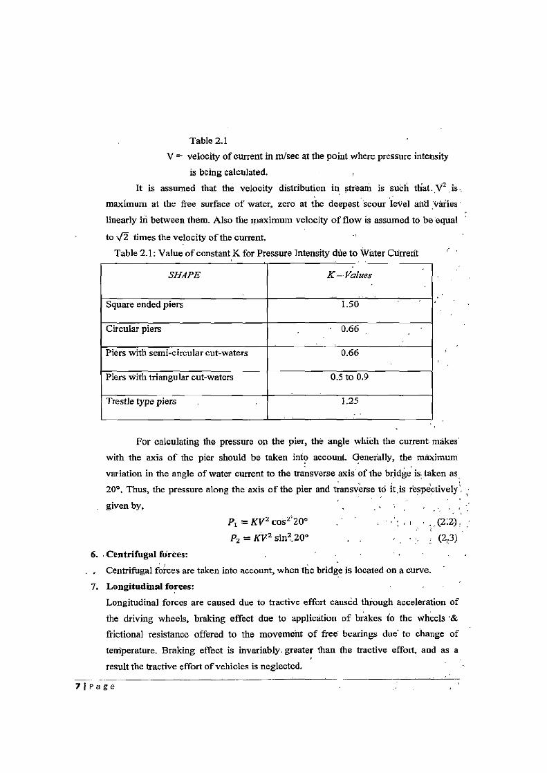
Table 2.1 V = velocity of current in m/sec at the point where pressure intensity
is being calculated.
It is assumed that the velocity distribution in stream is such that. V2 is., maximum at the free surface of water, zero at the deepest'scour level and varies'
linearly in between them. Also the maximum velocity of flow is assumed to be equal
to fl times the velocity of the current.
Table 2.1: Value of constant K for Pressure Intensity due to Water Current
SHAPE K— Values
Square ended piers 1.50
Circular piers 0.66
Piers with semi-circular cut-waters 0.66
Piers with triangular cut-waters 0.5 to 0.9
Trestle type piers 1.25
For calculating the pressure on the pier, the angle which the current makes'
with the axis of the pier should be taken into account. Generally, the maximum
variation in the angle of water current to the transverse axis of the bridge is taken as,
200. Thus, the pressure along the axis of the pier and transverse to it, is respectively',
given by,
P1 =KV 2 cos2 20° ,(2:2).
P2 = KV 2 sin2.20° , , (2,3)
6. Centrifugal forces: -
Centrifugal forces are taken into account, when the bridge is located on a curve.
7. Longitudinal forces: Longitudinal forces are caused due to tractive effort caused through acceleration of
the driving wheels, braking effect due to application of brakes to the wheels '&
frictional resistance offered to the movement of free bearings due to change of
temperature. Braking effect is invariably, greater than the tractive effort, and as a
result the tractive effort of vehicles is neglected.
7j Page
8. Seismic forces:
Seismic force acts on all loads, which posses mass at their centre of gravity. Seismic forces acting in horizontal direction, along longitudinal and transverse aids of the
bridge are considered. Forces acting in the vertical directions are comparatively small, and are hence neglected. During earthquake, water in river will apply hydrodynamic
force on the submerged portion of pier. Seismic forces are considered to act only in one direction at a time.
All the above loads are classified into different loading cases as discussed below.
1. Normal (N) Case loading: It includes dead load, live load, buoyant force, wind load,
forces due to water current, centrifugal forces, braking force/tractive force &
horizontal shear force at hinge bearings due to the effect of braking force, wind load.
2. Temperature (T) Case loading: It includes loads due to frictional restraint to
temperature movement at bearings.
3. Seismic (S) Case loading; It includes seismic forces acting in horizontal forces acting in horizontal direction.
Considering the probability of earthquake with other forces, it is generally assumed
that earthquake and wind forces will not occur simultaneously and so only one can be
considered at a time. Taking all the case loading into accounts, pier is analyzed for three
different load combinations: Normal (N) Case, Normal and Temperature (N + T) Case &
Normal, Temperature and Seismic (N ± T + S) Case.
Longitudinal forces acting on the bridge like braking effort/tractive effort, frictional
resistance at the bearings and seismic forces acting on live load and bridge superstructure will
produce horizontal shear force at the bearings. The horizontal shear force will be calculated
for different load combinations as discussed above, and later is incorporated into their
respective case of load combinations.
Stresses developed into the pier due to different loads and forces are calculated individually, and the resultant maximum stress acting on the pier is worked out for different
load combinations. The resultant maximum stress for each load combination should be within
the permissible stress limits. For brick masonry in cement mortar, permissible compressive
stress is I MPa and permissible tensile stress is 0.10 MPa. In stone masonry, compressive
stress is limited to 1.5 NlPa and tensile stress is limited to 0.10 MPa. Permissible stresses for
concrete are given in Table 21 of IS: 456-2000', for different grades of concrete. Table 2.1
shows the permissible stresses for plain concrete used in bridge analysis and design.
81 Pa ge _—
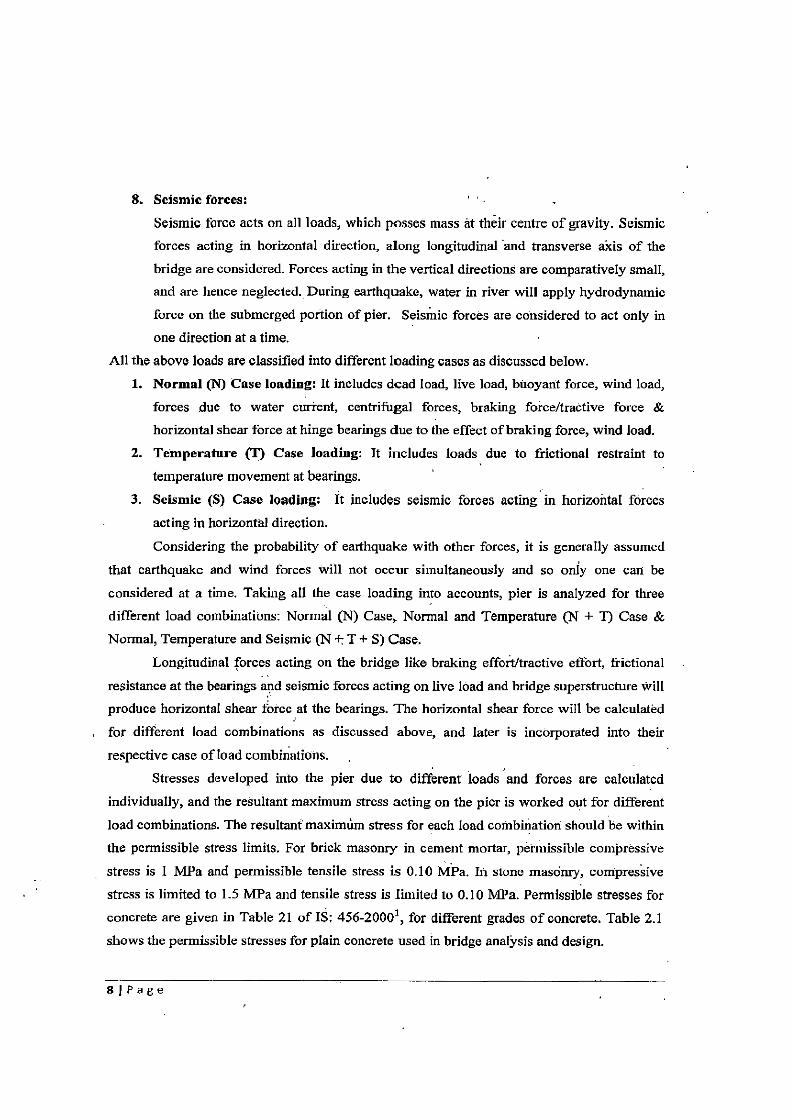
Table 2.2: Permissible Stresses in Concrete
Grade of Concrete
Permissible Stresses in Concrete (in MPa)
For Compression For Tension.
M l0 2:5. -
M 15 4.0 0.6
M20 5.0 0.8
M25 6.0 0.9
M30 8.0 1.0
M35 9.0 1.1
M40 10.0 1.2
M45 11.0 1.3
MS0 12.0 1.4
IRC: 6-20006 allows the increase in permissible stresses of concrete for different load combinations. For Normal and Temperature (N + T) case i.e. when the effect of temperature is considered, permissible stress can be increased by 15 percent.' Finally, • for Normal, Temperature and Seismic (N + T + S) case permissible stress can be exceeded by 50% if the maximum stresses in piers for the worst loading combination are indie than the permissible stress, it is required to redesign the piers in order to bring maximum stresses within the permissible limit. 2.4 CONCLUSIONS
The types and the features of piers and pier caps usually employed for bridge crossings have been briefly discussed together with analysis methodology and permissible stresses for design.
91Page
CHAPTER 3
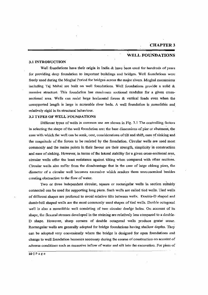
WELL FOUNDATIONS 3.1 INTRODUCTION
Well foundations have their origin in India & have been used for hundreds of years
for providing deep foundation to important buildings and bridges. Well foundations were freely used during the Moghal Period for bridges across the major rivers. Moghal monuments
including Taj Mahal are built on well foundations. Well foundations provide a solid &
massive structure. This foundation has maximum sectional modulus for a given cross-
sectional area. Wells can resist large horizontal forces & vertical loads even when the
unsupported length is large in scourable river beds. A well foundation is monolithic and,
relatively rigid in its structural behaviour.
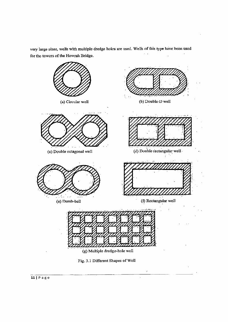
3.2 TYPES OF WELL FOUNDATIONS Different types of wells in common use are shown in Fig. 3.1 The controlling factors
in selecting the shape of the well foundation are: the base dimensions of pier or abutment, the
ease with which the well can be sunk, cost, considerations of tilt and shift, ease of sinking and
the magnitude of the forces to be resisted by the foundation. Circular wells are used most
commonly and the mains points in their favour are their strength, simplicity in construction
and ease of sinking. However, in terms of the lateral stability for a given cross-sectional area,
circular wells offer the least resistance against tilting when compared with other sections.
Circular wells also suffer from the disadvantage that in the case of large oblong piers, the
diameter of a circular well becomes excessive which renders them uneconomical besides
creating obstruction to the flow of water.
Two or three independent circular, square or rectangular wells in section suitably
connected can be used for supporting long piers. Such wells are called tied wells. Tied wells
of different shapes are preferred to avoid relative tilts between wells. Double-D shaped and
dumb-bell shaped wells are the most commonly used shapes of tied wells. Double octagonal
well is also a monolithic well consisting of two circular dredge holes. On account of its
shape, the flexural stresses developed in the steining are relatively less compared to a double-
D shape. However, sharp corners of double octagonal wells produce gratei scour.
Rectangular wells are generally adopted for bridge foundations having shallow depths. They
can be adopted very conveniently where the bridge is designed for open foundations and
change to well foundation becomes necessary during the course of construction on account of
adverse conditions such as excessive inflow of water and silt into the excavation. For piers of
101P age
(a) Circular well
(c) Double octagonal well
(e) Dumb-bell
very large sizes, wells with multiple dredge holes are used. Wells of this type have been used
for the towers of the Howrah Bridge.
(b) Double-D well
(d) Double rectangular well
(f) Rectangular well
(g) Multiple dredge-hole well
Fig. 3.1 Different Shapes of Well
111 P a g e
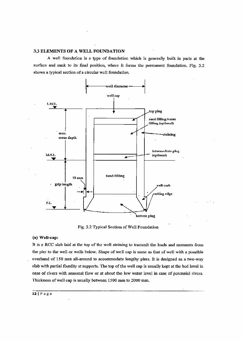
3.3 ELEMENTS OF A WELL FOUNDATION
A well foundation is a type of foundation which is generally built in parts at the
surface and sunk to its final position, where it forms the permanent foundation. Fig. 3.2
shows a typical section of a circular well foundation.
tt —well diameter s{
well cap
L.W.L.
top plug
sand filling /water filling (optional)
max. stetntng scour depth
intermediate plug i4LS.L (optional)
I
Sand filling Ta AUII
grip length well curb
~— rnning edge
F.t.
bottom plug
Fig. 3.2 Typical Section of Well Foundation
(a) Well-cap:
It is a RCC slab laid at the top of the well steining to transmit the loads and moments from
the pier to the well or wells below. Shape of well cap is same as that of well with a possible
overhand of 150 mm all-around to accommodate lengthy piers. It is designed as a two-way
slab with partial fixedity at supports. The top of the well cap is usually kept at the bed level in
case of rivers with seasonal flow or at about the low water level in case of perennial rivers.
Thickness of well cap is usually between 1500 mm to 2000 mm.
121 P a g e
(b) Steining:
It is the main body of the well which transfers load to the base of the foundation. Steining is normally of reinforced concrete. Minimum grade of concrete used in steining is M20 with cement content not less than 310 kg/m'. To facilitate well sinking an off-set of 75 mm to 100 min is provided in well steining at its junction with the well curb.
The thickness of well steining should not be less tan 500 mm nor less than that given by Eq. 3.1.
t = KDiTE, (3.1)
where, t = minimum thickness of concrete steining, m, D = external diameter of circular well or dumb bell shaped well or smaller
plan dimension of twin D well,"m, L = depth of well in m below L.W.L. or top of well cap whichever is greater, .. K = a constant depending On the nature of subsoil and steining material (taken
as 0.30 for circular well and 0.039 for twin —,D well for concrete steining in sandy strata and 10% more than the corresponding value in the case of clayey soil).
(c) Well curb: It is the wedge shaped RCC ring beam located at the lower portion of the well steining provided to facilitate sinking. Well curb carries cutting edge for the well and is made up of reinforced concrete using controlled concrete of grade M25. The cutting edge usually consists of a mild steel equal angle of side 150 mm. In case blasting in anticipated, the outer face of the well curb should be protected with 6 mm thick steel plate and the inner face'shbuld have 10 mm thick plate up to the top of the curb and 6,mm plate further up to a heiglitof 3 m' above the top of the curb.
(d) Bottom plug: After the well is sunk to the required depth, the base of the well is plugged with concrete. This is called the bottom plug. It acts like an inverted dome supported by the steining on all the sides and transmits the load to the subsoil and acts as a raft against soil pressure from. below. Minimum grade of concrete used in bottom plug is M15. Thickness of bottom plug should not be less than the half of dredge-hole diameter nor less than the value calculated in Eq. 3.2.
t2 =8 f~(3+r9), (3.2)
where, W = total bearing pressure at the base of well,
13 P age
t = flexural strength of concrete in bottom plug,
0.7 7 , and,
V = Poisson's ratio for concrete, 0.18 to 0.20. (e) Top plug:
The top plug is an unreinforced concrete plug, generally provided with a thickness of about
600 mm beneath the well cap to transmit the loads from the pier to the steining. Minimum
grade of concrete used in top plug is M15.
The space inside the well between the bottom of the top plug and the top of bottom plug is usually filled with clean sand, so that the stability of the well against overturning is
increased. While this practice is good in case of wells resting on sand or rock, the desirability
of sand filling for wells resting on clayey strata is doubtful, as this increases the ]bad on the
foundation and may lead to greater settlement. In the latter case, the sand filling is done only
for the part of well up to scour level, and remaining portion is left free.
(f) Intermediate plug:
As discussed above, for wells resting on clayey strata, it is not preferable to fill the space
inside the well completely with sand. In such cases, sand filling is not done or sand is filled
up to the scour level. A concrete plug covering the filling is usually provided, known as
intermediate plug. Usually, thickness of intermediate plug is taken as 500 mm.
3.4 ANALYSIS AND DESIGN OF WELL FOUNDATION
In order to design the well foundation, maximum depth oLscour should be,deterthined
first since the maximum scour depth decides the depth of the well foundation.
3.4.1 DETERMINATION OF MAXIMUM SCOUR DEPTH The codes IRC: 78-20008 and IS:3955-19675 recommend that the maximum scour
depth in a stream should be ascertained, whenever possible, by actual soundings at or near the
site proposed for the bridge, during or immediately after a flood before the scour holes have
had time to silt up appreciably. In case actual soundings are not possible, depth of scour in
stream can be ascertained using theoretical methods taking into account the velocity of
stream, characteristics of the river bed materials, and many other factors.
The IRC: 78-2000$ recommended formula for calculating the mean depth of scour
below High Flood Level (HFL) for natural channels flowing over scourable bed is as follows: 1
z dsm = 1.34 (
(ala
1. ,
f
where, Db = Design discharge per meter width of effective linear waterway, m3/ms,
(3.3)
14 1 P age
Q , Q is the design discharge in the stream in m3/s and L = 4.76
is the linear waterway, m, K,f = Silt factor for a representative sample of the bed'rrlaterial obtained up
to the level of the anticipated deepest scour; and,
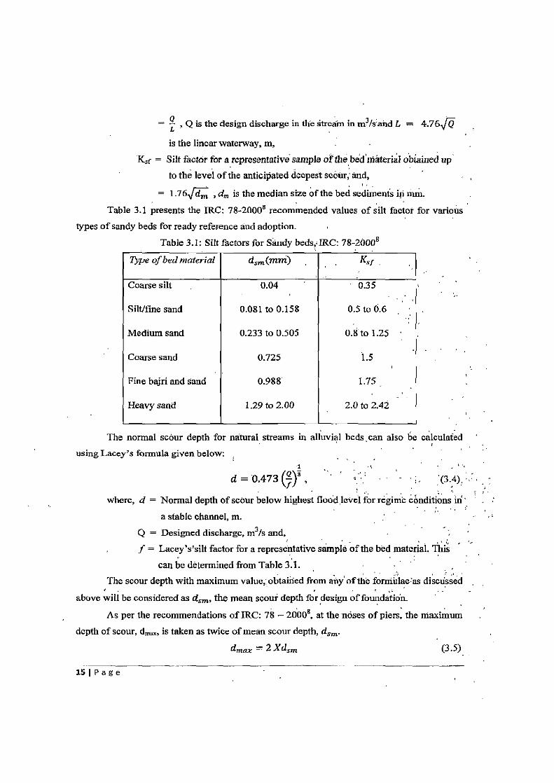
= 1.76 dm , d,,, is the median size of the bed sediments in inm. Table 3.1 presents the IRC: 78-20008 recommended values of silt factor for various
types of sandy beds for ready reference and adoption. Table 3.1: Silt factors for Sandy beds,; IRC: 78-20008
Type of bed material dsm (mm)
Coarse silt 0.04 0.35
Silt/fine sand 0.081 to 0.158 0.5 to 0.6
Medium sand 0.233 to 0.505 0.8 to 1.25
Coarse sand 0.725 1.5
Fine bajri and sand 0.988 1.75
Heavy sand 1.29 to 2.00 2.0 to 2.42
The normal scour depth for natural streams in alluvial beds can also be calculated
using Lacey's formula given below:
d = 0.473 ~1}3 ,
where, d = Normal depth of scour below highest flood level for regime conditions iri' a stable channel, m.
Q = Designed discharge, m3/s and, f = Lacey's'silt factor for a representative sample of the bed material. This
can be determined from Table 3.1. The scour depth with maximum value,: obtained from any of the forniulae:as discussed
above will be considered as dsm, the mean scour depth for design of foundation.
As per the recommendations of IRC: 78 — 2000,8 at the noses of piers, the maximum depth of scour, dm,, is taken as twice of mean scour depth, dsm.
dmax = 2 Xdsm (3.5)
151 P age

The well foundation shall be taken to such a depth that it is safe against scour. Apart
from this, the depth of the well foundation should also be sufficient from considerations of
bearing capacity, settlement stability and suitability of strata at the founding level. Invariably,
the well foundation in all cases shall be taken down to a depth which will provide sufficient
grip. The grip length below the anticipated maximum scour level shall not be less than 1/3 a the maximum anticipated depth of scour below H.F.L.
3.4.2 LOADS FOR WELL FOUNDATION DESIGN After determining the depth of the well foundation, the dimensions of well and its
different components are empirically assumed.
The following loads are considered for the analysis and design of well foundation:
1. Dead load
2. Live load
3. Buoyancy
4. Wind load
5. Horizontal force due to water current
6. Centrifugal forces
7. Longitudinal forces
8. Seismic forces
9. Horizontal shear forces at bearings due to longitudinal forces and seismic forces 10. Forces due to tilt and shift.
The loads mentioned above are discussed in Section 2.2 of Chapter 2. These loads are
calculated with respect to the bridge superstructure and substructure and correspondingly, the
total vertical load, the total horizontal forces acting along the longitudinal direction and the transverse direction of bridge and the moments about the transverse and longitudinal axis of
the bridge are obtained for the design of the well foundation. Moments due to shift and tilt of
wells are also be included in the analysis of the well.
3.4.3 STABILITY ANALYSIS OF WELL FOUNDATIONS The stability of well foundation under the action of lateral loads, particularly large
magnitudes of seismic forces, depends on the passive resistance of the soil on the sides and the base of the well. As the lateral load increases for a given magnitude of the vertical load,
the soil deformation increases disproportionately when compared with the deformation at
initial loading. Under the combined action of vertical and lateral loads the mechanism of
sharing the applied loads between the sides and the base of the well also gets significantly
modified. Hence, the behaviour of the soil at ultimate loads is different form that at the elastic
16IPage
stage which is assumed to prevail under vertical loading. The IRC: 45-19727 . therefor specifies two checks, one for soil pressures under working loads and the other. for the facto of safety available with respect to.ultimate strength of the surrounding the well.
r As per IRC: 45-19727; the resistance of the soil surrounding the well is checked using
a. Elastic theory b. Plastic theory (also called as Ultimate Resistance Method)
The following assumptions are made in computing soil pressure using elastic theory: i. The soil surrounding the well and below the base is perfectly elastic, homogeneous
and obeys Hooke's law ii. Under design loads, the lateral deflections are so small that the unit soil reaction `p'
increases linearly with increasing lateral deflections z'. Hence p = KHZ'
where, Ka is the coefficient of horizontal subgrade reaction at the base. iii. The coefficient of horizontal subgrade reaction increases linearly with depths in the
case of cohesionless soils. iv. The well is assumed to be a rigid body, • subjected to ah extemalunidireotional
horizontal force `H' and moment `M' at scour level. As a consequence of the above assumptions, the'pressure distribution is parabolic on the sides of the well and linear at the base. -
The elastic theory gives the soil pressure in the sides and the base of the well under design loads. However, to determine the actual factor of safety against failure it is necessary to calculate the ultimate soil resistance which is done by assuming plastic behaviour of the soil at ultimate loads. For checking the ultimate load capacity of the well foundation, the applied loads are multiplied by suitable load factors for various load combinations and the ultimate resistance is reduced by appropriate under-strength factors and the two are then' compared..
A step-wise description of these two methods of analysis of well foundations is given below:
Both the above methods are applicable if the well foundation is resting on non-cohesive soil like sand and is surrounded by the same soil below the maxim ' scour' level.
The above methods should not be used for analysis if the depth of embedment of the well is less than 0.5 times the width of foundation in the direction of the principal lateral forces.
17 P age
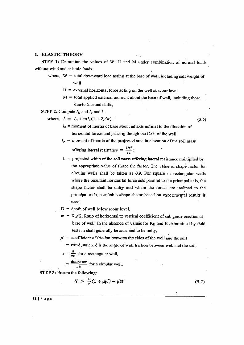
1. ELASTIC THEORY
STEP 1: Determine the values of W, H and M under, combination of normal loads without wind and seismic loads
where, W = total downward load acting at the base of well, including self weight of well '
H = external horizontal force acting on the well at scour level
M total applied external moment about the base of well, including those
due to tilts and shifts, STEP 2: Compute Ip and I. and !;
where, I = 18 + mli,(1 + 2µ'a), (3.6) la = moment of inertia of base about an axis normal to the direction of
horizontal forces and passing though the C.G. of the well. 1, = moment of inertia of the projected area in elevation of the soil mass
offering lateral resistance = LDX
iz
L = projected width of the soil mass offering lateral resistance multiplied by
the appropriate value of shape the factor. The value of shape factor for
circular wells shall be taken as 0.9. For square or rectangular wells
where the resultant horizontal force acts parallel to the principal axis, the
shape factor shall be unity and where the forces are inclined to the
principal axis, a suitable shape factor based on experimental results is
used.
D = depth of well below scour level, m = KH/K; Ratio of horizontal to vertical coefficient of sub grade reaction at
base of well. In the absence of values for KH and K determined by field tests m shall generally be assumed to be unity,
u' = coefficient of friction between the sides of the well and the soil = tand, where S is the angle of wall friction between well and the soil,
a = B for a rectangular well, 2D
= diameter for a circular well. rrD
STEP 3; Ensure the following:
H> r (1+1Ft')—µW
(3.7)
181 P a g e
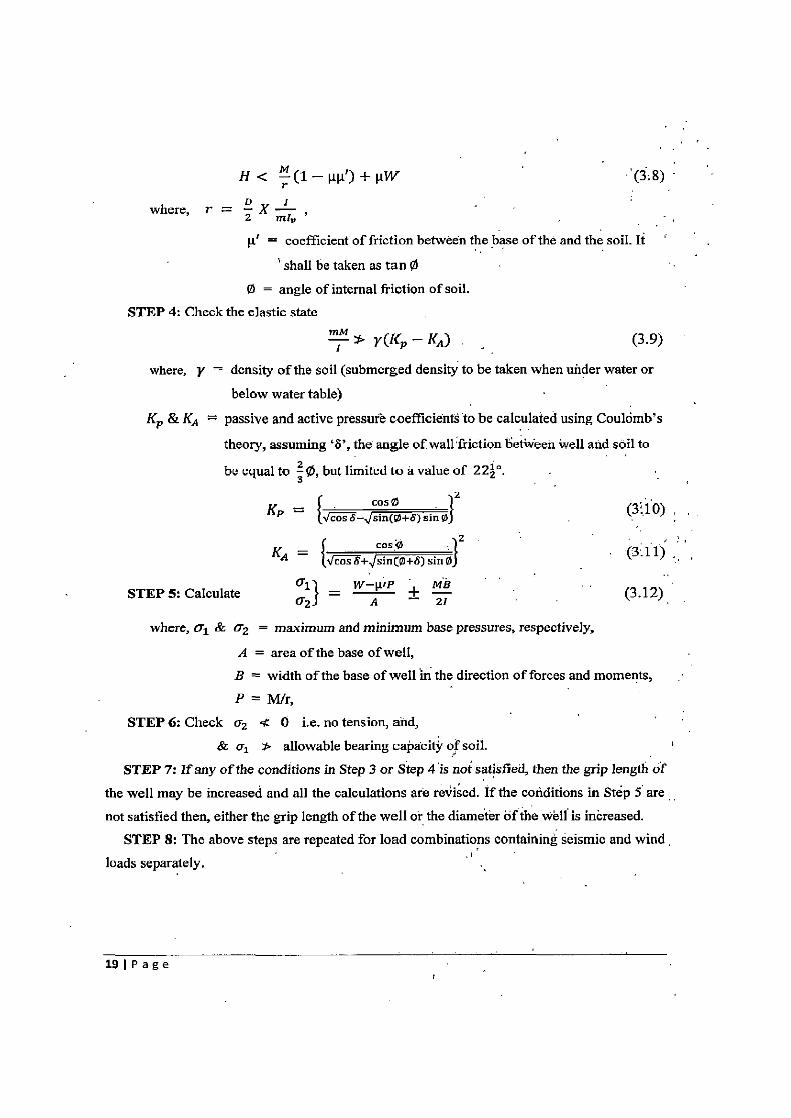
H< M(1—µµ')+µW
I where, r = 2 X mt v
= coefficient of friction between the base of the and the soil. It
shall be taken as tan 0 0 = angle of internal friction of soil.
STEP 4: Check the elastic state
Z ! 1. y(Kp — KA) (3.9)
where, y = density of the soil (submerged density to be taken when under water or
below water table)
Kp & KA = passive and active pressure coefficients to be calculated using Coulomb's
theory, assuming `S', the angle of wall friction between Well and soil to
be equal to ~ 0, but limited to a value of 222°.
_ cos0
KP — { cos s— sin(o+S) sin 0) (310)
cosQ Z .
KA = { cos S+ since+6) sin 0) (3.11)
STEP 5: Calculate 1} = W Ai 'P + MB (3.12)
where, Ul & Qz = maximum and minimum base pressures, respectively,
A = area of the base of well, B = width of the base of well in the direction of forces and moments, P=M/r,
STEP 6: Check a2 < 0 i.e. no tension, and, & a, allowable bearing capacity of soil.
STEP 7: If any of the conditions in Step 3 or Step 4 is not satisfied, then the grip length of the well may be increased and all the calculations are revised. If the conditions in Step 5 are not satisfied then, either the grip length of the well or the diameter of the well is increased.
STEP 8: The above steps are repeated for load combinations containing seismic and wind loads separately. I ,
191 P a g e
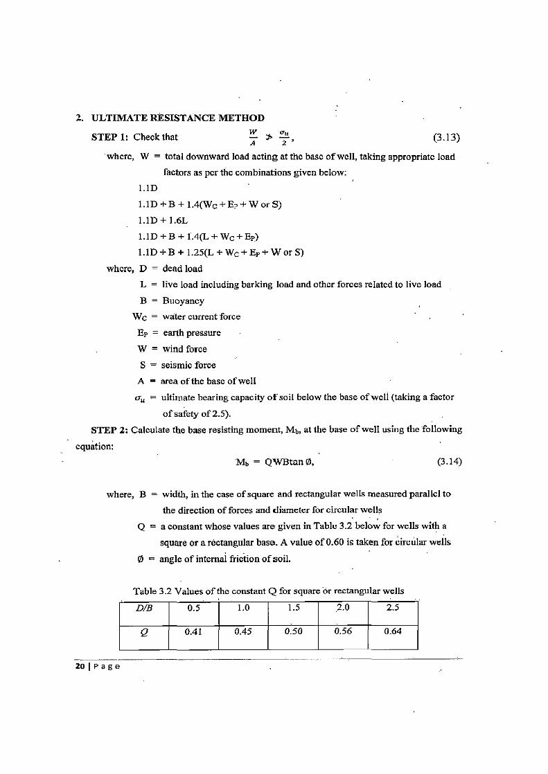
2. ULTIMATE RESISTANCE METHOD
STEP 1: Check that A ) z , (3.13)
where, W = total downward load acting at the base of well, taking appropriate load
factors as per the combinations given below: 1.1D
1.1D +B + 1.4(Wc+EP+ W or S)
1.1D+1.6L
1.1D+B+1.4(L+Wc+Ep)
1.1D + B + 1.25(L + Wc + Ep + W or S)
where, D = dead load L = live load including barking load and other forces related to live load
B = Buoyancy
We = water current force
EP = earth pressure
W = wind force
5 = seismic force A = area of the base of well
Qu = ultimate bearing capacity of soil below the base of well (taking a factor
of safety of 2.5). STEP 2: Calculate the base resisting moment, Mb, at the base of well using the following
equation: Mb = QWBtan 0, (3.14)
where, B = width, in the case of square and rectangular wells measured parallel to
the direction of forces and diameter for circular wells
Q = a constant whose values are given in Table 3.2 below for wells with a
square or a rectangular base. A value of 0.60 is taken for circular wells
0 = angle of internal friction of soil.
Table 3.2 Values of the constant Q for square or rectangular wells
DIB 0.5 1.0 1.5 2.0 2.5
Q 0.41 0.45 0.50 0.56 0.64
20 1 P a g e
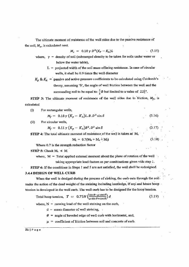
The ultimate moment of resistance of the well sides due to the passive resistance of
the soil, M5, is calculated next.
MS = 0.10 y D3 (Kp — KA )L - ( 3.15)
where, y = density of soil (submerged density to be taken for soils under water or ,
below the water table),
L = projected width of the soil mass offering resistance. In case of circular
wells, it shall be 0.9 times the well diameter
K p & KA = passive and active pressure coefficients to be calculated using Coulomb's
theory, assuming `S', the angle of wall friction between the well and the
surrounding soil to be equal to 3 0 but limited to a value of 222°.
STEP 3: The ultimate moment of resistance of the well sides due to friction, M f , is
calculated
(i) For rectangular wells,
M,r = 0.18 y (K p — KA)L. B. D Z sin S (3.16)
(ii) For circular wells,
M f = 0.11 y (K p — K482 . D2 sin 6 (3.17)
STEP 4: The total ultimate moment of resistance of the well is taken as Mt
Mt = 0.7(Mp + Ms Mr) (3.18) Where 0.7 is the strength reduction factor
STEP 5: Check M, 4z M where, M = Total applied external moment about the plane of rotation of the well
taking appropriate load factors as per combinations given vide step 1.
STEP 6: If the conditions in Steps 1 and 5 are not satisfied, the well shall be redesigned.
3.4.4 DESIGN OF WELL CURB When the well is dredged during the process of sinking, the curb cuts through the soil.
under the action of the dead weight of the steining including kentledge, if any. and hence hoop
tension is developed in the well curb. The well curb has to be designed for the hoop'tension. sin o—µcos A
Total hoop tension, T = 0.75N ( ) d (3.19) µsin A+cos A
where, N = running load of the well steining on the curb,
d = mean diameter of well steining, .
0 = angle of beveled edge of well curb with horizontal, and,
µ = coefficient of friction between soil and concrete of curb.
211 P age
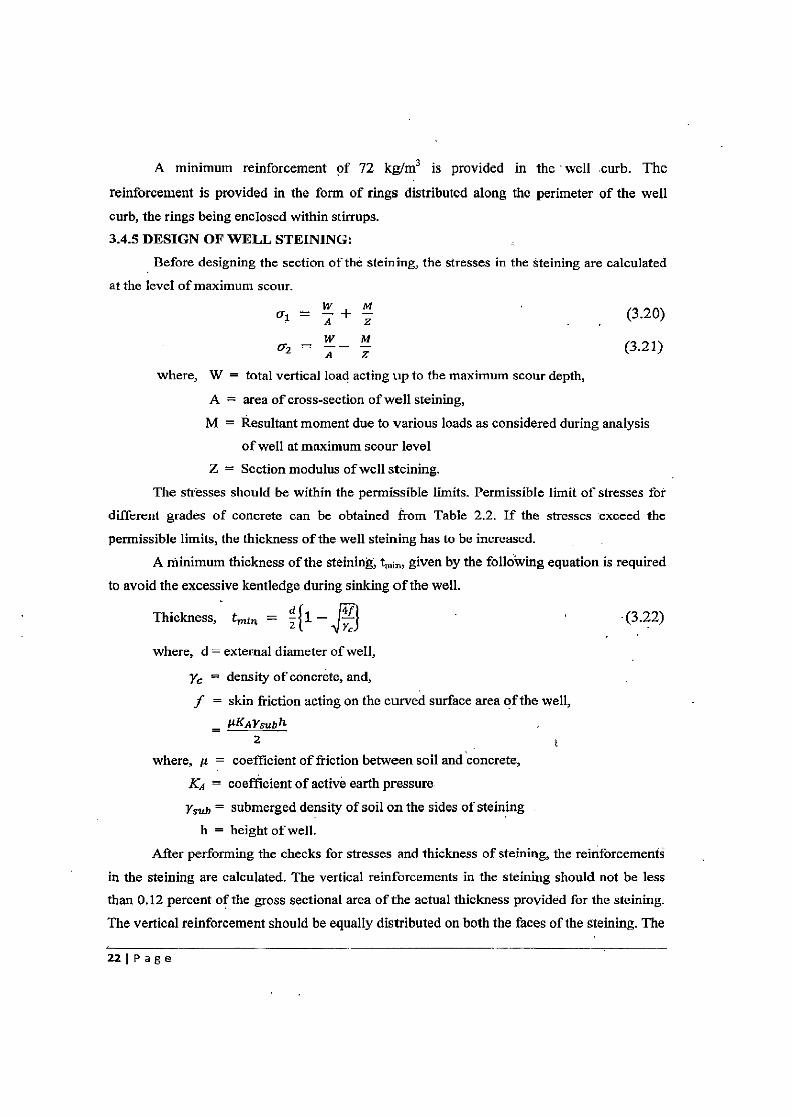
A minimum reinforcement of 72 kg/m3 is provided in the - well curb. The
reinforcement is provided in the form of rings distributed along the perimeter of the well
curb, the rings being enclosed within stirrups. 3.4.5 DESIGN OF WELL STEINING:
Before designing the section of the steining, the stresses in the steining are calculated
at the level of maximum scour.
Ql = A + Z (3.20)
(3.21)
where, W = total vertical load acting up to the maximum scour depth,
A = area of cross-section of well steining,
M = Resultant moment due to various loads as considered during analysis
of well at maximum scour level
Z = Section modulus of well steining.
The stresses should be within the permissible limits. Permissible limit of stresses for
different grades of concrete can be obtained from Table 2.2. If the stresses exceed the
permissible limits, the thickness of the well steining has to be increased.
A minimum thickness of the steining, t, given by the following equation is required
to avoid the excessive kentledge during sinking of the well.
Thickness, train = Z {i — r 4f (3.22)
where, d = external diameter of well,
yc = density of concrete, and,
f = skin friction acting on the curved surface area of the well,
__ FUKAYsu6h 2
where, p = coefficient of friction between soil and concrete,
KA ° coefficient of active earth pressure
ymb = submerged density of soil on the sides of steining
h = height of well.
After performing the checks for stresses and thickness of steining, the reinforcements
in the steining are calculated. The vertical reinforcements in the steining should not be less than 0.12 percent of the gross sectional area of the actual thickness provided for the steining.
The vertical reinforcement should be equally distributed on both the faces of the steining. The
221 P a g e
vertical reinforcement should be tied up with hoop steel not less than 0.04 percent of the volume per unit length of the steining. 3.4.6 DESIGN OF BOTTOM PLUG
The bottom plug has to be checked for minimum thickness given by the following equations,
tZ = 1.16r 2 (For circular wells), (3.23) is
z
tZ af~t3gb2 (For rectangular wells), (3.24)
where, r = radius of well at the base q = unit bearing pressure against the base of the Well,
fc = flexural strength of concrete used in bottom plug
b = short side of well a = short side/long side ratio of well. .
3.4.7 DESIGN OF WELL CAP A well cap is needed to transfer the loads and moments from the pier to the well. The
shape of the wall cap is normally kept the same as of the, well with a possible overhang of 150 mm. The top of the well cap is usually kept at about the low 'water level in 'case of, perennial rivers. The well cap is designed as a two-way reinforced concrete slab resting over
the top of well. The support conditions are taken partially restrained. , The design of the well cap is carried out by assuming that the load from the pier acts ,
on an imaginary circle having an area equal to the area of dispersion of the loads transferred from the pier to the well cap.
Since the well-cap is assumed to be partially restrained by the steining, the moments in the well-cap are calculated for circular patch loading and for U.D.L. (self-weight of well cap) for the following two conditions:
(1) Well cap freely supported on steining (2) Well cap fully clamped on steining
Condition 1: Well cap freely supported on the steining Take, i9 = Poisson's ratio of concrete,
w weight of well cap per unit area V = vertical load acting on the well-cap h = effective diameter of well-cap,
Mr & Mr are the radial and the tangential moments in well-cap, respectively.
231 Page
In the first instance, the moments.in the well cap due to vertical loads transferred from the pier and the self weight of the well cap are determined.
(i) Moments beneath loaded area due to circular patch loading
Mr — 4z [1 + (1 + fl)ln (d)] (3.25)
Mt = [1 + (1 + fl)ln (d)] 4a (3.26)
d = diameter of equivalent circular patch loading (ii) Moments beneath unloaded area due to circular patch loading
Mr = — 4 (1 + a9)ln(f) (3.27)
Mc = —-[(1 —0) (1 + i9)1n( )] (3.28)
Atsupport,d = h; f = a = 1 h
The radial and tangential moments in the well cap due to U.D.L. are given by
Mr = 64z C3 + fl) [1 — /Z] (3.29) lh
Me = 64z [(3 + fl) — (1 + 3t9) ç]
At centre, d = 0; = h = o
Atsupport,d = h; _ 1 = 1 h
Condition 2: Well cap fully clamped at support (i) Moments beneath loaded area due to circular patch loading
Mr = 4 [(1 +,9)ln (d)] (3.31)
Mt = as [C) + fl)In l (3.32)
d = diameter of equivalent circular patch loading. (ii) Moments beneath unloaded area due to circular patch loading
Mr as [\z{h/2 (1 —'9) — (1 +,9)ln(c) — 1] (3.33)
Mt = 4rz i9(1— 6): (1 + i9)ln(c) — 1] (3.34)
At support, d = h; ( = K = h
The radial and tangential moments in the well cap due to U.D.L. are given by
Mr = 642 [(1 + fl) — (3 + z9)~2] (3.35)
241 P age
Mr = bz2 [(1 ±9) - (1 + 3fl)X2] (3.36)
At centre, d = 0; i; = d = 0
Atsupport,d = h; Ic = h = 1.
If Ml is the resultant moment per metre length of the pier, then maximum reactive moment at
the support = ±'X0.5 = -4- e'
Hence, the maximum moment at the centre of, the well cap dtie to moments
transferred form pier = + B
The maximum moment at the edges of the well cap due to moments transferred from
pier = ±T
The resultant moments for the design of the wel];cap section at mid-spdn.and at supports can be found out as follows.
M~ m = (Mean radial moment due to patch loads beneath the loaded area)
+ (Mean radial moment due to U.D.L. at the centre of well-cap) + (moment at the centre of well cap due to moments transferred from pier)
Medgo = (Mean radial moment due to patch loads beneath unloaded area)' + (Mean radial moment due to U.D.L. at the support of well=cap) + (moment at the edges of well cap due to moments transfefred from'pier)
Hence, the reinforcement at the centre of the well-cap is calculated for the moment Mcenire and the reinforcement at the edges of well-cap' is calculated for the moment Ivledse. Half of the main tension reinforcement at the centre and at the support sections of the well cap is provided on the compression face. All reinforcement in the well-cap is provided as an orthotropie mesh.
The well-cap is finally checked for punching shear as per IS:456-20001 . 3.5 CONCLUSIONS
The role and the feamtes of well foundations have been discussed in 'this 'chapter. This stability analysis of well' foundations has been explained and the design of various components has been briefly reviewed.
251 P a g e
CHAPTER 4
PILE FOUNDATIONS 4.1 INTRODUCTION
Piles are relatively long and slender members used to transfer loads through weak soil
or water to deeper soil or rock strata having a high bearing capacity. Piles are usually installed in clusters/group to provide foundations for bridges. A pile foundation may have
vertical piles or batter piles or a combination of vertical and batter piles. Well foundations are
provided to the bridges, only when soils with high bearing capacity are available at the
shallow depths in ground, in order to resist loads and moments transferred by well to the soil.
It is not preferable to use well foundations, when low bearing strata like clay is present in the
ground up to greater depths.
The uses of piles for bridge foundations are justified in the following cases;
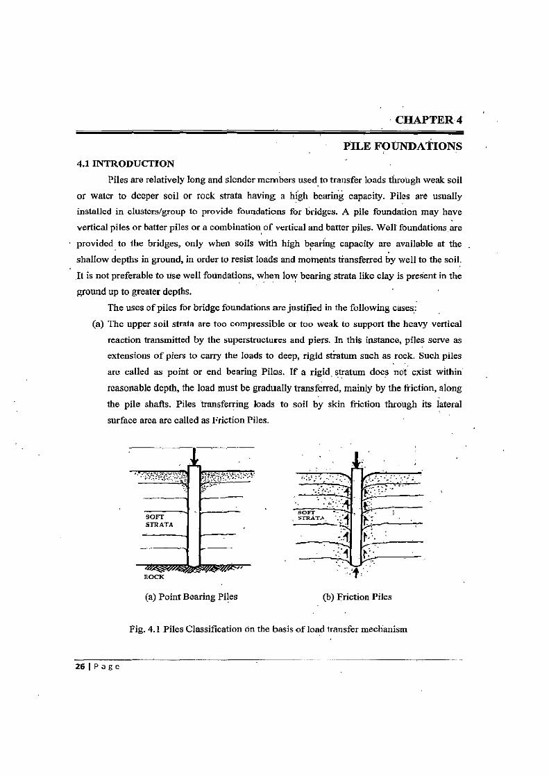
(a) The upper soil strata are too compressible or too weak to support the heavy vertical
reaction transmitted by the superstructures and piers. In this instance, piles serve as extensions of piers to carry the loads to deep, rigid stratum such as rock. Such piles
are called as point or end bearing Piles. If a rigid, stratum does not exist within
reasonable depth, the load must be gradually transferred, mainly by the friction, along
the pile shafts. Piles transferring loads to soil by skin friction through its lateral
surface area are called as Friction Piles.
SOFT -
STRATA 4 b-
41 f .
ROCK
(a) Point Bearing Piles (b) Friction Piles
Fig. 4.1 Piles Classification on the basis of load transfer mechanism
261 Pa ge
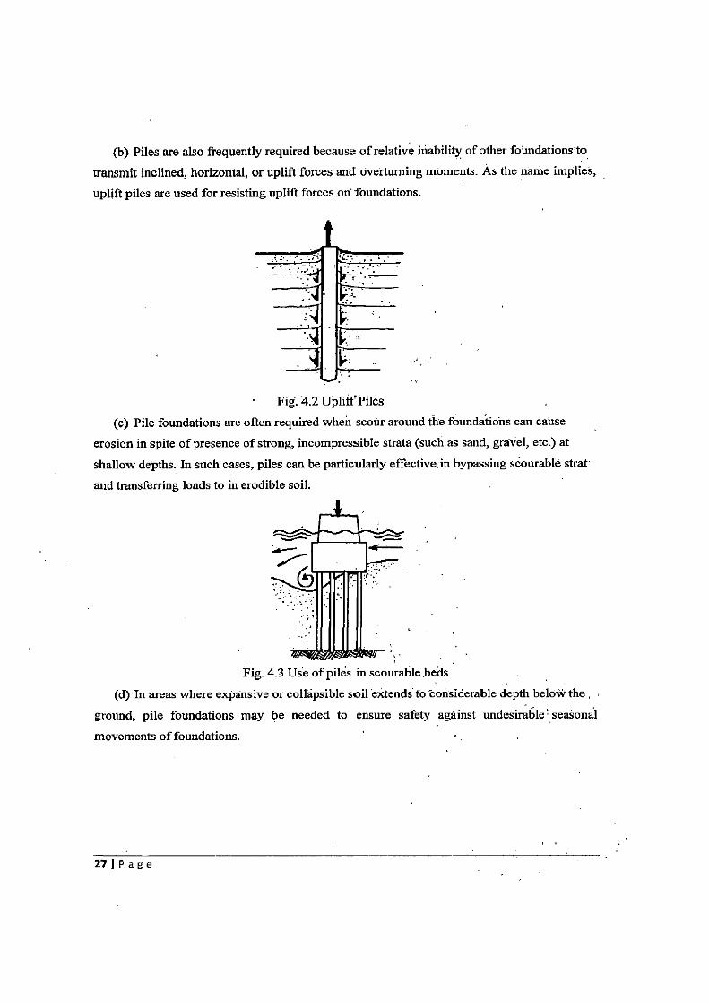
(b) Piles are also frequently required because of relative inability of other foundations to
transmit inclined, horizontal, or uplift forces and overturning moments. As the name implies,
uplift piles are used for resisting uplift forces on foundations.
Fig. 4.2 Uplift`Piles
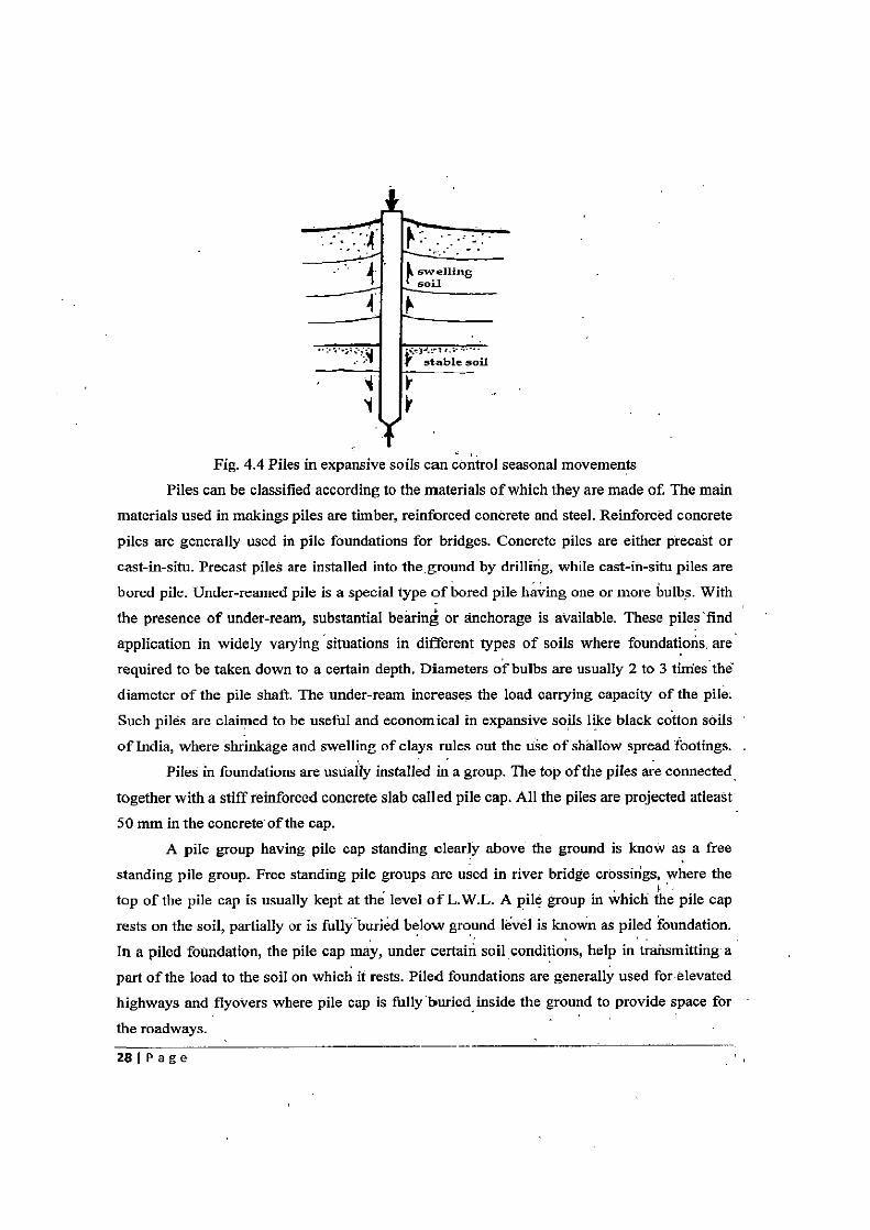
(c) Pile foundations are often required when scour around the foundations can cause
erosion in spite of presence of strong, incompressible strata (such as sand, gravel, etc.) at
shallow depths. In such cases, piles can be particularly effective.in bypassing scourable strat
and transferring loads to in erodible soil.
Fig. 4.3 Use of piles in scourable beds
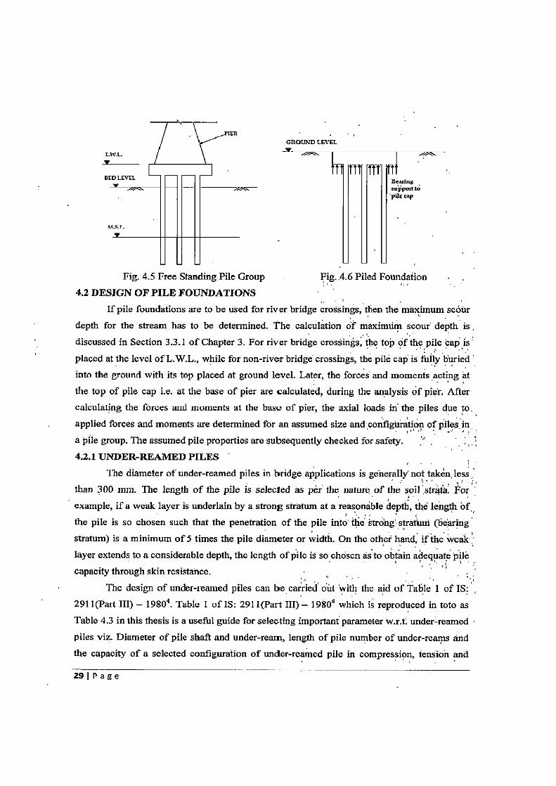
(d) In areas where expansive or collapsible soil extends to considerable depth below the
ground, pile foundations may be needed to ensure safety against undesirable seasonal
movements of foundations.
27 1 P age
4r A swelling
1 soil
stable soil
Fig. 4.4 Piles in expansive soils can control seasonal movements
Piles can be classified according to the materials of which they are made of. The main
materials used in makings piles are timber, reinforced concrete and steel. Reinforced concrete
piles are generally used in pile foundations for bridges. Concrete piles are either precast or
cast-in-situ. Precast piles are installed into the.ground by drilling, while cast-in-situ piles are
bored pile. Under-reamed pile is a special type of bored pile having one or more bulbs. With
the presence of under-ream, substantial bearing or anchorage is available. These piles find
application in widely varying situations in different types of soils where foundations, are
required to be taken down to a certain depth. Diameters of bulbs are usually 2 to 3 tines the
diameter of the pile shaft. The under-ream increases the load carrying capacity of the pile.
Such piles are claimed to be useful and economical in expansive soils like black cotton soils
of India, where shrinkage and swelling of clays rules out the use of shallow spread footings.
Piles in foundations are usually installed in a group. The top of the piles are connected
together with a stiff reinforced concrete slab called pile cap. All the piles are projected atleast
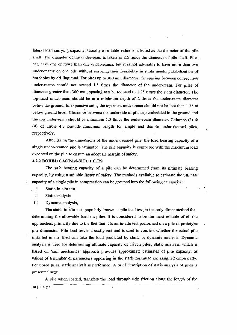
50 mm in the concrete of the cap. A pile group having pile cap standing clearly above the ground is know as a free
standing pile group. Free standing pile groups are used in river bridge crossings, where the
top of the pile cap is usually kept at the level of L.W.L. A pile group in which the pile cap
rests on the soil, partially or is fully-buriedbelow ground level is known as piled foundation.
In a piled foundation, the pile cap may, under certain soil conditions, help in transmitting a
part of the load to the soil on which it rests. Piled foundations are generally used for elevated
highways and flyovers where pile cap is fully buried inside the ground to provide space for
the roadways.
281 P age
GROUND LEVEL
L S
BI
Fig. 4.5 Free Standing Pile Group Fig. 4.6 Piled Foundation 4.2 DESIGN OF PILE FOUNDATIONS
If pile foundations are to be used for river bridge crossings, then the maximum scour depth for the stream has to be determined. The calculation of maximum scour depth is discussed in Section 3.3.1 of Chapter 3. For river bridge crossings, the to of the pile cap is placed at the level of L.W.L., while for non-river bridge crossings, the pile cap is fully buried into the ground with its top placed at ground level. Later, the forces and moments acting at the top of pile cap i.e. at the base of pier are calculated, during the analysis of piet. After calculating the forces and moments at the base of pier, the axial loads in the piles due to. applied forces and moments are determined for an assumed size and configuration of piles in a pile group. The assumed pile properties are subsequently checked for safety. 4.2.1 UNDER-REAMED PILES
The diameter of under-reamed piles in bridge applications is generally not taken, less than 300 mm. The length of the pile is selected as per the nature of the soil ,stra(a. For example, if a weak layer is underlain by a strong stratum at a reasonable depth, the length of the pile is so chosen such that the penetration of the pile into the strong'stratum (bearing stratum) is a minimum of 5 times the pile diameter or width. On the other hand, if the weak layer extends to a considerable depth, the length of pile is so chosen as to obtain adequate pile capacity through skin resistance.
The design of under-reamed piles can be carried out with the aid of Table 1 of IS: 2911(Part III) — 1980°. Table I of IS: 2911(Part III) — 1980 which is reproduced in toto as Table 4.3 in this thesis is a useful guide for selecting important parameter w.r.t. under-reamed piles viz. Diameter of pile shaft and under-ream, length of pile number of under-reams and the capacity of a selected configuration of under-reamed pile in compression, tension and
291Page
lateral load carrying capacity. Usually a suitable value is selected as the diameter of the pile shaft. The diameter of the under-ream is taken as 2.5 times the diameter of pile shaft. Piles
can have one or more than one under-reams, but it is not advisable to have more than two under-reams on one pile without ensuring their feasibility in strata needing stabilization of
boreholes by drilling mud. For piles up to 300 mm diameter, the spacing between consecutive
under-reams should not exceed 1.5 times the diameter of the under-ream. For piles of
diameter greater than 300 mm, spacing can be reduced to 1.25 times the stem diameter. The top-most under-ream should be at a minimum depth of 2 times the under-ream diameter
below the ground. Tn expansive soils, the top-most under-ream should not be less than 1.75 ni
below ground level. Clearance between the underside of pile cap embedded in the ground and
the top under-ream should be minimum 1.5 times the under-ream diameter. Columns (3) &
(4) of Table 4.3 provide minimum length for single and double under-reamed piles,
respectively.
After fixing the dimensions of the under-reamed pile, the load bearing capacity of a
single under-reamed pile is estimated. The pile capacity is compared with the maximum load
expected on the pile to ensure an adequate margin of safety.
4.2.2 BORED CAST-IN-SITU PILES
The safe bearing capacity of a pile can be determined from its ultimate bearing
capacity, by using a suitable factor of safety. The methods available to estimate the ultimate
capacity of a single pile in compression can be grouped into the following categories: i. Static-in-situ test. ii. Static analysis,
iii. Dynamic analysis,
The static-in-situ test, popularly known as pile load test, is the only direct method for
determining the allowable load on piles. It is considered to be the most reliable of all the, approaches, primarily due to the fact that it is an in-situ test performed on a pile of prototype
pile dimension. Pile load test is a costly test and is used to confirm whether the actual pile
installed in the filed can take the load predicted by static or dynamic analysis. Dynamic
analysis is used for determining ultimate capacity of driven piles. Static analysis, which is
based on `soil mechanics' approach provides approximate estimates of pile capacity, as
values of a number of parameters appearing in the static formulae are assigned empirically.
For bored piles, static analysis is performed. A brief description of static analysis of piles is
presented next.
A pile when loaded, transfers the load through skin friction along the length of the
30 l P a g e
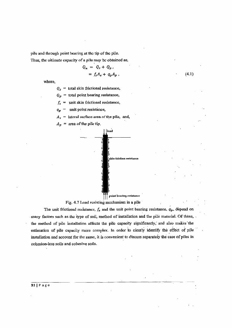
pile and through point bearing at the tip of the pile.
Thus, the ultimate capacity of a pile may be obtained as,
Qu = Qs + Qp .
= f:As+ gpAp, (4.1)
where,
Qs = total skin frictional resistance,
Qp = total point bearing resistance,
fs = unit skin frictional resistance,
qp unit point resistance,
AS = lateral surface area of the pile, and,
Ap = area of the pile tip.
stance
IIIpoint bearing resistance
Fig. 4.7 Load resisting mechanism in a pile
The unit frictional resistance, fs and the unit point bearing resistance, qp. depend on
many factors such as the type of soil, method of installation and the pile material. Of these,
the method of pile installation affects the pile capacity significantly, and also makes the
estimation of pile capacity more complex. In order to clearly identify the effect of pile
installation and account for the same, it is convenient to discuss separately the case of piles in
cohesion-less soils and cohesive soils.
31 Page
Piles in Cohesion-less soil:
As suggested in Eq. 4.1, the pile capacity can be obtained as the sum of point bearing resistance and skin friction resistance.
Point Bearing Resistance:
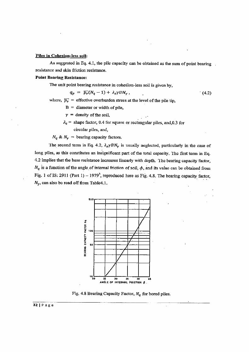
The unit point bearing resistance in cohesion-less soil is given by,
9p = Pv(Ny — 1) + A yBNy , _ (4.2)
where, p„ = effective overburden stress at the level of the pile tip,
B = diameter or width of pile,
y = density of the soil,
A, = shape factor, 0.4 for square or rectangular piles, and,0.3 for circular piles, and,
Nq & N y = bearing capacity factors.
The second term in Eq. 4.2, d syBNr is usually neglected, particularly in the case of
long piles, as this constitutes an insignificant part of the total capacity. The first term in Eq.
4.2 implies that the base resistance increases linearly with depth. The bearing capacity factor, Nq is a function of the angle, of internal friction of soil, q5, and its value can be obtained from
Fig. 1 of IS: 2911 (Part 1) — 1979, reproduced here as Fig. 4.8. The bearing capacity factor, N., can also be read off from Table4.1.
z 0
20 25 30 35 40 45 ANGLE OF INTERNAL FRICTION 0
Fig. 4.8 Bearing Capacity Factor, Nq for bored piles.
321 P age
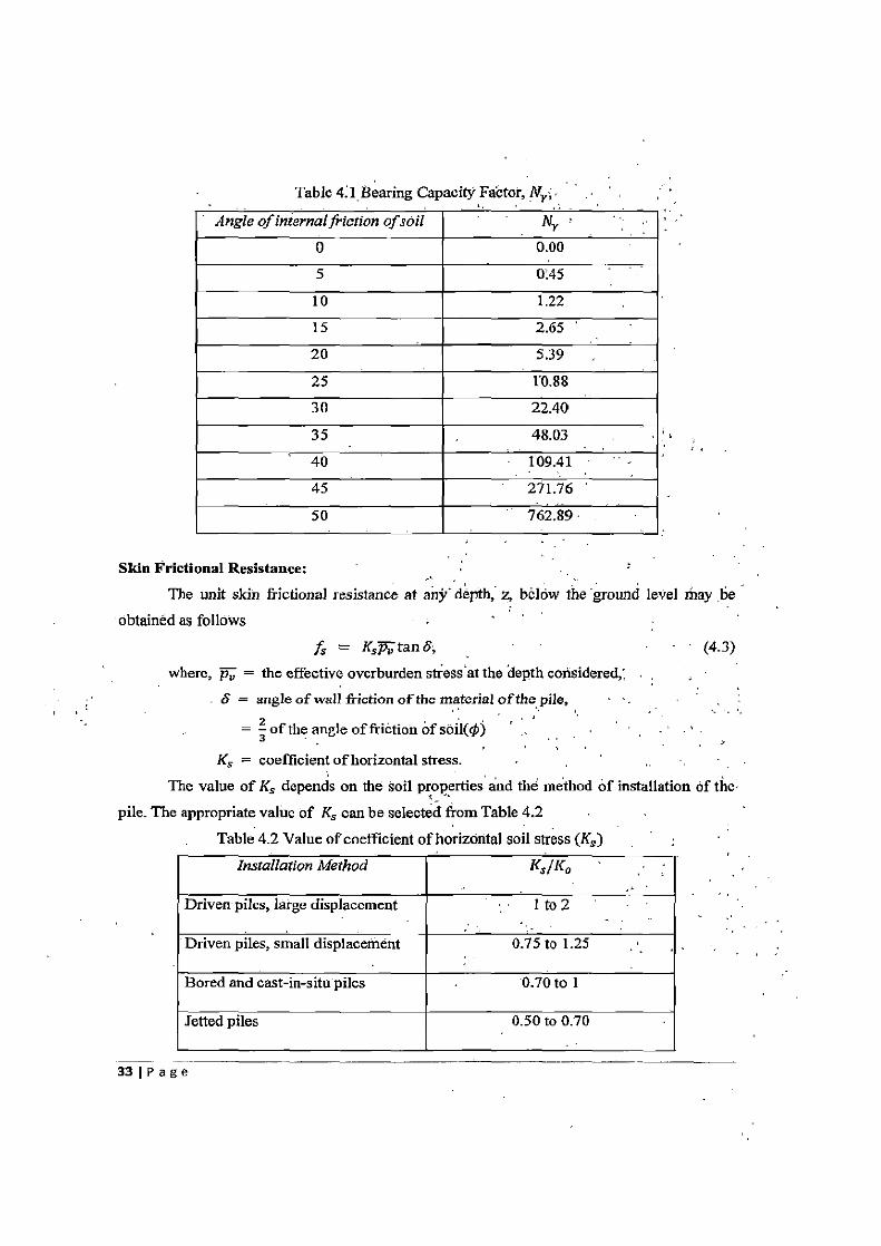
Table 4A Bearing Capacity Factor, N1;
• Angle of internal friction of soil Ny 0 0.00 5 0.45
10 1.22 15 2.65 20 5.39 25 1'0.88 30 22.40
35 48.03 40 109.41 - 45 271.76 50 762.89
Skin Frictional Resistance: The unit skin frictional resistance at any' depth, z, blow the ground level may be
obtained as follows
fs = K5 tan 6, - (4.3) where, p, = the effective overburden stress at the depth considered„
S = angle of wall friction of the material of the pile,
= of the angle of friction of soil(@ -
Ks = coefficient of horizontal stress. The value of Ks depends on the soil properties and the method of installation of the
pile. The appropriate value of Ks can be selected from Table 4.2 Table 4.2 Value of coefficient of horizontal soil stress (Ks )
Installation Method Ks/Ko
Driven piles, large displacement 1 to 2
Driven piles, small displacement 0.75 to 1.25
Bored and cast-in-situ piles 0.70 to 1
Jetted piles 0.50 to 0.70
33 1 P a g e
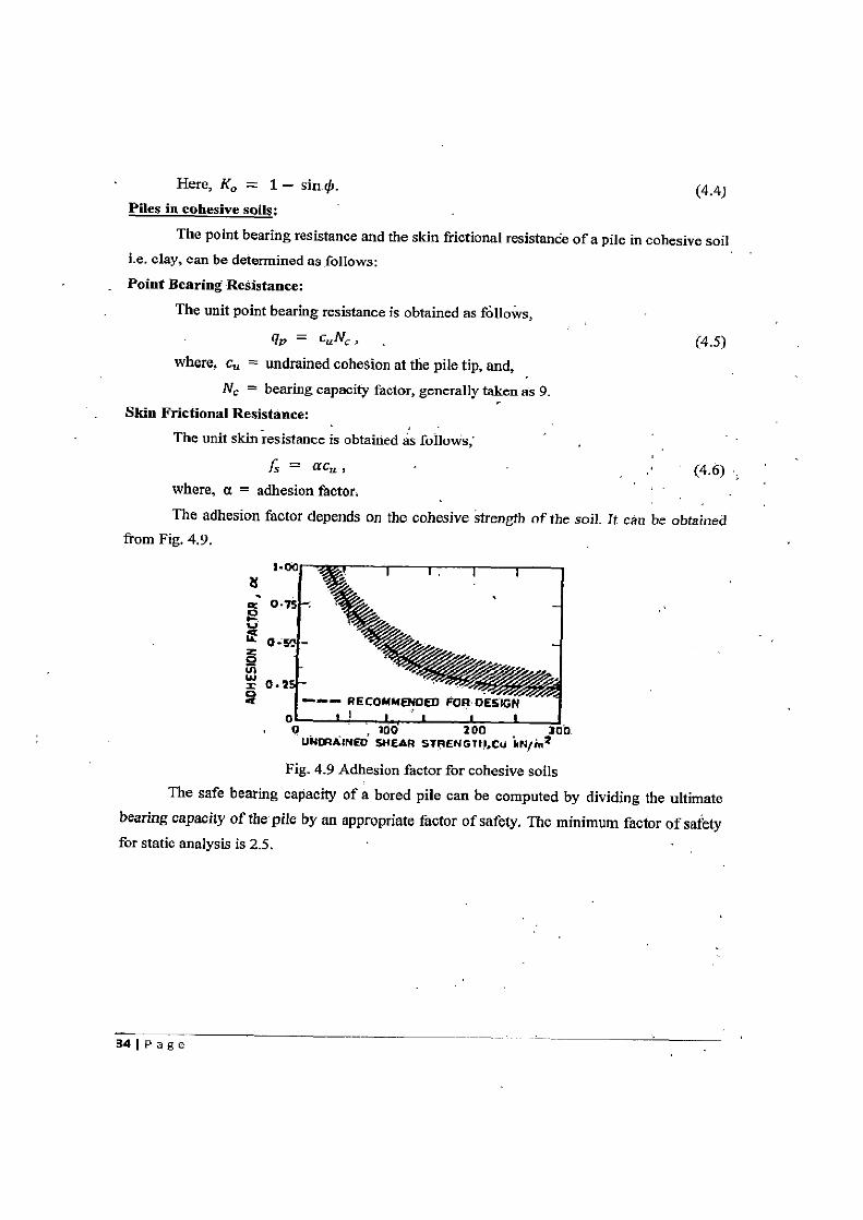
Here, K. = 1 — sin . (4.4) Piles in cohesive soils;
The point bearing resistance and the skin frictional resistance of a pile in cohesive soil i.e. clay, can be determined as follows: Point Bearing Resistance:
The unit point bearing resistance is obtained as follows, 9v = c.Nc , (4.5)
where, c„ = undrained cohesion at the pile tip, and, Nc = bearing capacity factor, generally taken as 9.
Skin Frictional Resistance: The unit skin resistance is obtained as follows,
fs = ac, , (4.6) where, a = adhesion factor.
The adhesion factor depends on the cohesive strength of the soil. It can be obtained from Fig. 4.9.
Nit
o O.Z
RECOMMENDED FOR DES
UNmAINED SHEAR STRENGTN;Cu MN/in2
Fig. 4.9 Adhesion factor for cohesive soils The safe bearing capacity of a. bored pile can be computed by dividing the ultimate
bearing capacity of the pile by an appropriate factor of safety. The minimum factor of safety for static analysis is 2.5.
34 1 P a g
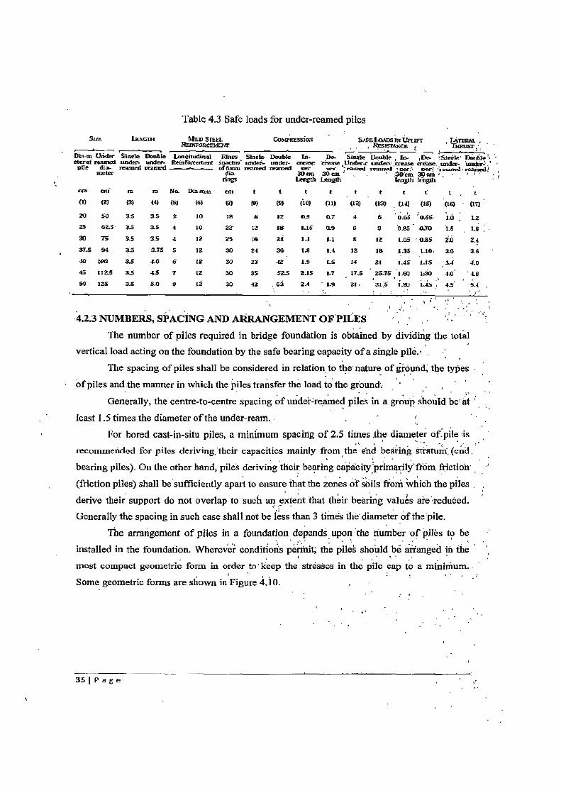
Table 4.3 Safe loads for under-reamed piles
Sty men. Mao Sme/. Co dnnsiwti SAM Il mr Vrut=r tA7raat, , Rro ro crML'jl' Rrs,ciiQn . T gosr,
Via-it, tinder SYnale Double L eieitadinat R1. Shots Double rn. The- Slane Doable , (n- De- 'Single! Double ' • eterof teaneed under w,den Re6trmietnent snacitn lode[- mules- crease case Undess under aerie Hesse tn- 'tmtr-1 -' pile dig- in tred maned demur reamed .raumi ner ire eanal received ,ore.•: neil :.z:u,wd, eevimdl melee dice 30 em 30 cm ' 3O'mt 30 em bogs Length Length Iengtli length
tm mf en in Na Dlanun an t t t t t t t t t t (1) (2) (3) (4) (51 (6) (7) (8) (9) (10) (11) (12) (13) (14) (15) (16) (17)
20 50 3$ 3.5 3 10 16 9 12 OS a7 4 6 Q.6' 0,S$ ID 12 25 02.5 - 3.5 3.5 4 10 22 12 I8 1.15 0.9 6 9 O.g5' 0.70 CIS i.s 20 7S 3.5 3.5 4 12 25 16 24 1-4 El S 12 105 ' 0.85 20 2.4 37.594 34 3.75 5 12 30 24 36 15' 1.4 12 I8 1.35 110. 30 '3.6 40 160 3.5 iO 6 12 30 23 -12 19 LS 14 21 1.45 1_1S 3.( 4.0 45 1125 33 4.5 7 12 30 35 52.5 2.15 1.7 17.5 25.75 1.60 1:30 -D a.8 50 125 35 5.0 9 12 30 42 63 2.1 - 1.9 2l. 31,5 1111 L.Is i5 i{
4.2.3 NUMBERS, SPACING AND ARRANGEMENT OF PILES The number of piles required in bridge foundation is obtained by dividing the total
vertical load acting on the foundation by the safe bearing capacity of a single pile. • . The spacing of piles shall be considered in relation to the nature of ground; the types
of piles and the manner in which the piles transfer the load to the ground. Generally, the centre-to-centre spacing of under=reamed piles in a group should be at
least 1.5 times the diameter of the under-ream. For bored cast-in-situ piles, a minimum spacing of 2.5 times the diameter of.pile is
recommended for piles deriving,'their capacities mainly .from the end bearing s$atuir, (end , bearing piles). On the other hand, piles deriving their bearing capacity'primarily'from friction (friction piles) shall be sufficiently apart to ensure that the zones of soils from which the piles . derive their support do not overlap to such an extent that their bearing values ai-e •reduced. Generally the spacing in such case shall not be less than 3 times the diameter of the pile.
The arrangement of piles in a foundation depends upon the number of piles to be installed in the foundation. Wherever conditions permit; the pile's should be arranged in the most compact geometric form in order to' keep the stresses in the pile cap to a minimum. Some geometric forms are shown in Figure 4.10.
S
35 P a g e
I_—S -1
s'pilas
5
to °,.(S O O I
I plies
—sss I
1 1 I 1 ~_oo_ s s s s
1 i s i
L-s T{
ai 4-s
S piles
,—s 3 Pita
spits'
10 piles 11 pllas
(a) For single footings
~ s s - s
o a w : s~~s ..S
w 5 w ,
Singly row for a wall s 5 5
Double row for a wall Triple row for a well ijll
tl
Fig. 4.10 Typical arrangement. of piles in`a group =
Piles in foundation can be arranged in a grid pattern, where the spacing between the
piles in longitudinal as well as transverse direction of the bridge remains the same.
After fixing the arrangement of piles in a group, the dimensions of the pile cap are
determined. A clear overhang of 100 mm to 150 mm should be provided in the pile cap
beyond the edge of the outermost pile in the group.
A minimum of three piles shall be provided in pile group. If the numbers of piles
provided in the foundation are three, then the connection of the pile cap with the piles is
361 P a g
assumed to be hinged connection i.e. pile cap can Transmit only forces and not the moments; from pier to the piles. If the number of piles in the pile group exceeds three; then a rigid connection is provided between the piles and the pile cap i.e. the pile cap is able to transmit
both forces and moments, from pier to the piles. The group capacity of piles is found by assuming the pile group'to behave"as a deep
footing. 4.2.4 SAFE BEARING CAPACITY OF PILE GROUPS
The group capacity of piles may be found assuming the pile group to behave as one
deep footing. 4.2.4(a) GROUP OF BORED CAST-IN-SITU PILES
The ultimate bearing capacity of the pile group in can be estimated as follows:
Pile Group in cohesion-less soil , For a pile group in sand, the values of the different parameters used for estimating the
ultimate bearing capacity of the pile group can be calculated as follows:
Qy = ffA5+ q,A, , (4.7)
fs = unit skin frictional resistance,
= K0 tan p , (4:8)
where, p„ = the effective overburden stress at the depth considered,
0 = angle of friction of soil, and,
Ko = 1 — sin , (4.9)
As = lateral surface area of the block enclosing the piles in the group,
qp = unit point resistance,
= cuNc , and, (4.10)
where, c,, = undrained cohesion at the; bottom of pile group, and;
Nc = bearing capacity factor, generally taken as 9,
A,, = base area enclosing all the piles in group.
For Pile Group in cohesive soil For pile group in clay, the values of different parameters used in estimating ultimate
bearing capacity of pile group can be calculated as follows: fs = unit skin frictional resistance,
= Cu, (4.11)
where, ca = undrained cohesion at the bottom of pile group.
-AS lateral surface area of the block enclosing the piles in the group,
37 I P age
qp = unit point resistance,
= cuNN , and, (4,12)
where, NN = bearing capacity factor, generally taken as 9,
AP = base area enclosing all the piles in group.
The safe bearing capacity of the pile group shall be taken as the smaller of the two
values given below: • nQu
FOS
• Qg
FOS
where, n = number of piles in group,
Qu = ultimate bearing capacity of a single pile,
Qg = ultimate bearing capacity of the pile group as estimated above,
FOS = Factor of Safety, generally taken as 3.
4.2.4(b) GROUP OF UNDER-REAMED PILES For under-reamed piles with a spacing of 2 times the diameter of the under-ream, the
safe bearing capacity of the pile group will be equal to the safe load on an individual pile
multiplied by the number of piles in the group. For piles at spacing of 1.5 times the diameter
of the under-ream, the safe bearing capacity of the pile group will be equal to 90 percent of
the safe load on an individual pile multiplied by the number of piles in the group.
The safe bearing capacity of a pile group shall be greater then the actual load
acting on the pile foundation. The vertical load acting on the foundation will also, include the
weight of pile cap. if the load acting on the foundation exceeds the safe bearing capacity of
the pile group, then the piles are redesigned or the numbers of piles in the group are increased
or the spacing between the piles is increased. In case of under-reamed piles, the number of
under-reams on each pile can also be increased to extend the safe load limit of the pile group.
Safe bearing capacity of the pile group is then re-estimated to check whether it is greater than
the loads acting on foundation.
38 1 P age
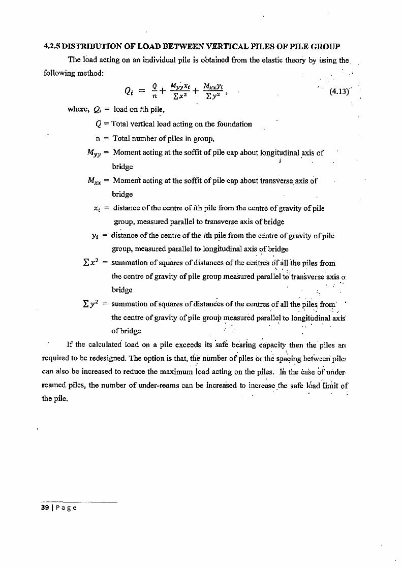
4.2.5 DISTRIBUTION OF LOAD BETWEEN VERTICAL PILES OF PILE GROUP The load acting on an individual pile is obtained from the elastic theory by using the
following method:
Qi = Q - MYYX1 + MxXZ` , (4.13), Ex Ey
where, Q; = load on ith pile,
Q = Total vertical load acting on the foundation
n = Total number of piles in group,
Myy = Moment acting at the soffit of pile cap about longitudinal axis of
bridge
Mxx = Moment acting at the soffit of pile cap about transverse. axis of
bridge
xj = distance of the centre of ith pile from the centre of gravity of pile
group, measured parallel to transverse axis of bridge
y j = distance of the centre of the ith pile from the centre of gravity of pile
group, measured parallel to longitudinal axis of bridge
x2 = summation of squares of distances of the centres of all the piles from
the centre of gravity of pile group measured parallel to'transverse axis o:
bridge
y2 = summation of squares of distances of the centres of all the piles, from
the centre of gravity of pile group measured parallel to longitudinal axis' of bridge
If the calculated load on a pile exceeds its safe bearing capacity then the piles an
required to be redesigned. The option is that, the number of piles or the spacing betweeri pile:
can also be increased to reduce the maximum load acting on the piles. In the case of under
reamed piles, the number of under-reams can be increased to increase the safe load limit of the pile.
39 1 Page
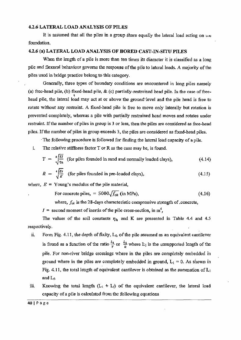
4.2.6 LATERAL LOAD ANALYSIS OF PILES It is assumed that all the piles in a group share equally the lateral load acting on «,,
foundation.
4.2.6 (a) LATERAL LOAD ANALYSIS OF BORED CAST-IN-SITU PILES When the length of a pile is more than ten times its diameter it is classified as a long
pile and flexural behaviour governs the response of the pile to lateral loads. A majority of the piles used in bridge practice belong to this category.
Generally, three types of boundary conditions are encountered in long piles namely (a) free-head pile, (b) fixed-head pile, & (c) partially-restrained head pile. In the case of free-
6 head pile, the lateral load may act at or above- the ground level and the pile head is free to
rotate without any restraint. A fixed-head pile is free to move only laterally but rotation is
prevented completely, whereas a pile with partially restrained head moves and rotates under
restraint. If the number of piles in group is 3 or less, then the piles are considered as free-head
piles. If the number of piles in group exceeds 3, the piles are considered as fixed-head piles.
- The following procedure is followed for finding the lateral load capacity of a pile.
i. The relative stiffness factor T or R as the case may be, is found.
T =
5 nh (for piles founded in sand and normally loaded clays), (4.14)
R = 4 K (for piles founded in pre-loaded clays), (4.15)
where, E = Young's modulus of the pile material,
For concrete piles, = 5000 f k (in MPa), (4.16)
where, fck is the 28-days characteristic compressive strength of .concrete,
I = second moment of inertia of the pile cross-section, in m4, The values of the soil constants 'lh and K are presented in Table 4.4 and 4.5
respectively.
ii. Form Fig. 4.11, the depth of fixity, Lf, of the pile assumed as an equivalent cantilever
is found as a function of the ratio T—' or R where L1 is the unsupported length of the
pile. For non-river bridge crossings where in the piles are completely embedded in
ground where in the piles are completely embedded in ground, Li = 0. As shown in
Fig. 4.11, the total length of equivalent cantilever is obtained as the summation of L1
and L.
iii. Knowing the total length (L + Lf) of the equivalent cantilever, the lateral load
capacity of a pile is calculated from the following equations
40 1 Page
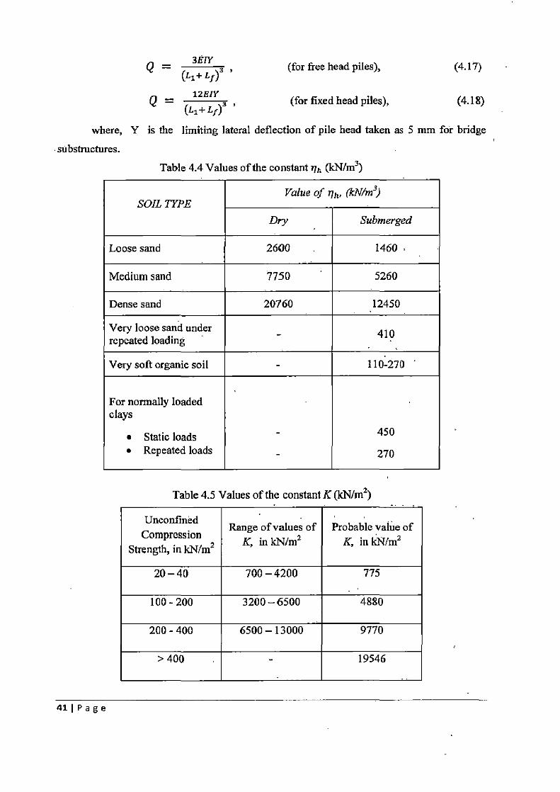
Q 38I _ Y (for free head piles), (4.17)
n _
12EIY (L1+L1)3 (for fixed head piles), (4.18)
C ,
where, Y is the limiting lateral deflection of pile head taken as 5 mm for bridge
substructures.
Table 4.4 Values of the constant i1h (kN/m3 )
Value of tlh, (kN/m3) SOIL TYPE
Dry Submerged
Loose sand 2600 1460
Medium sand 7750 5260
Dense sand 20760 12450
Very loose sand under - 410 repeated loading
Very soft organic soil - 110-270
For normally loaded clays
• Static loads - 450 • Repeated loads - 270
Table 4.5 Values of the constant K (kN/m2 )
Unconfined Compression
Strength, in kN/m2
Range of values of K, in kN/m2
Probable value of K, in kN/m2
20-40 700-4200 775
100-200 3200-6500 4880
200-400 6500 —13000 9770
> 400 - 19546
41 Page
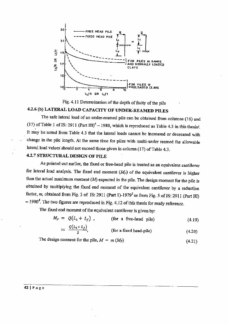
Z~ -FREE HEAD PILE Q Q ---- FIXED HEAD PILE T T
71\ Lt _ Lt
-,` L1 1.9 T
J
o \ I FOR PILES IN SANDS 17 \ J AND NORMALLY LOADED
f CLAYS J
FOR PILES IN 190 2 L 16 8
1,~J PRELDADED CLAYS
Lt/R OR LI/I
Fig. 4.11 Determination of the depth of fixity of the pile 4.2.6 (b) LATERAL LOAD CAPACITY OF UNDER-REAMED PILES
The safe lateral load of an under-reamed pile can be obtained from columns (16) and (17) of Table I of IS: 2911 (Part III)4 —1980, which is reproduced as Table 4.3 in this thesis/. It may be noted from Table 4.3 that the lateral loads cannot be increased or decreased with
change in the pile length. At the same time for piles with multi-under reamed the allowable
lateral load values should not exceed those given in column (17) of Table 4.3. 4.2.7 STRUCTURAL DESIGN OF PILE
As pointed out earlier, the fixed or free-head pile is treated as an equivalent cantilever for lateral load analysis. The fixed end moment (MF) of the equivalent cantilever is higher than the actual maximum moment (M) expected in the pile. The design moment for the pile is
obtained by multiplying the fixed end moment of the equivalent cantilever by a reduction factor, m, obtained from Fig. 3 of IS: 2911 (Part 1)-19793 or from Fig. 5 of IS: 2911 (Part III) —19804. The two figures are reproduced in Fig. 4.12 of this thesis for ready reference.
The fixed end moment of the equivalent cantilever is given by:
MF = Q(L1 + L f ) , (for a free-head pile) (4.19)
Q (L1+ L f) 2 (for a fixed head-pile) (4.20)
The design moment for the pile, M = m (MF) (4.21)
42 I I' a g e
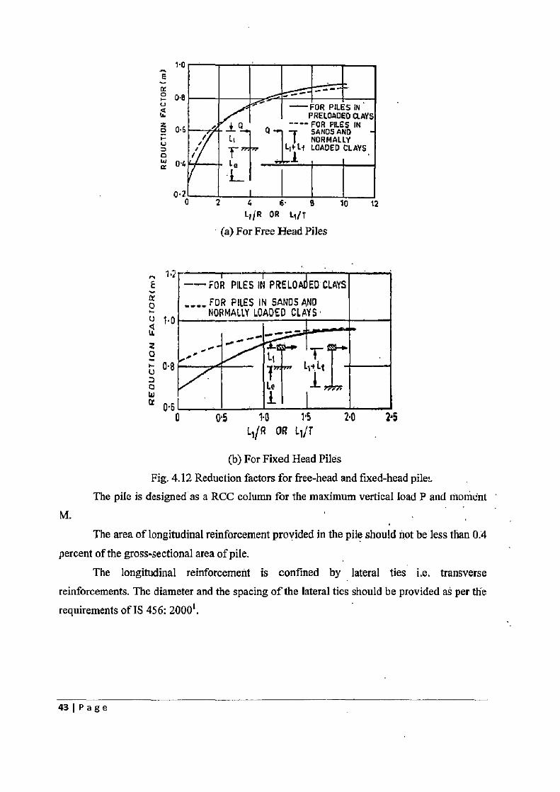
— FOR PILES IN PRELOADEO CLAYS
Q Li
---- L~*Li
FO SANDS AND IN AND LOADED CLAYS ,
Le
1.0
0.2
„ 1.2 E
0 Q 1.0
0 U 0.8 0 W ct 0.6
4 6• B 10 12 L;JR OR L7 /T
(a) For Free Head Piles
--FOR PILES IN PRELOA ED CLAYS _
FOR PILES IN SANDS AND NORMALLY LOADED CLAYS
L1 Lt
Lle i
0 015 10 1-5 2.0 2.5 L,/R OR L1/T
(b) For Fixed Head Piles Fig. 4.12 Reduction factors for free-head and fixed-head pile,-
The pile is designed as a RCC column for the maximum vertical load P and moment ISTA
The area of longitudinal reinforcement provided in the pile should not be less than 0.4 percent of the gross-sectional area of pile.
The longitudinal reinforcement is confined by lateral ties i.e. transverse reinforcements. The diameter and the spacing of the lateral ties should be provided as per the requirements of IS 456: 2000'.
43~Page
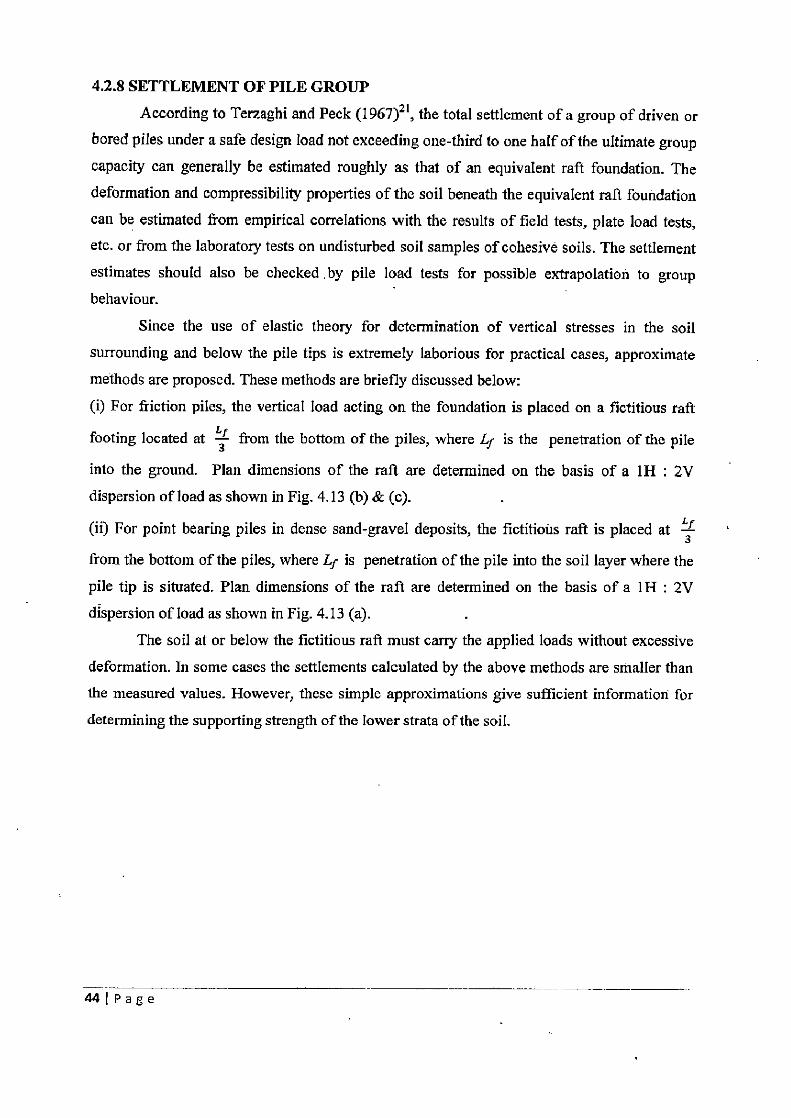
4.2.8 SETTLEMENT OF PILE GROUP
According to Terzaghi and Peck (1967)21, the total settlement of a group of driven or bored piles under a safe design load not exceeding one-third to one half of the ultimate group
capacity can generally be estimated roughly as that of an equivalent raft foundation. The
deformation and compressibility properties of the soil beneath the equivalent raft foundation
can be estimated from empirical correlations with the results of field tests, plate load tests, etc. or from the laboratory tests on undisturbed soil samples of cohesive soils. The settlement
estimates should also be checked by pile load tests for possible extrapolation to group behaviour.
Since the use of elastic theory for determination of vertical stresses in the soil
surrounding and below the pile tips is extremely laborious for practical cases, approximate
methods are proposed. These methods are briefly discussed below: (i) For friction piles, the vertical load acting on the foundation is placed on a fictitious raft
footing located at L3 from the bottom of the piles, where Lf is the penetration of the pile
into the ground. Plan dimensions of the raft are determined on the basis of a 1H : 2V dispersion of load as shown in Fig. 4.13 (b) & (c).
(ii) For point bearing piles in dense sand-gravel deposits, the fictitious raft is placed at `f 3
from the bottom of the piles, where Lf is penetration of the pile into the soil layer where the
pile tip is situated. Plan dimensions of the raft are determined on the basis of a 1H : 2V
dispersion of load as shown in Fig. 4.13 (a).
The soil at or below the fictitious raft must carry the applied loads without excessive
deformation. In some cases the settlements calculated by the above methods are smaller than
the measured values. However, these simple approximations give sufficient information for
determining the supporting strength of the lower strata of the soil.
44IPage
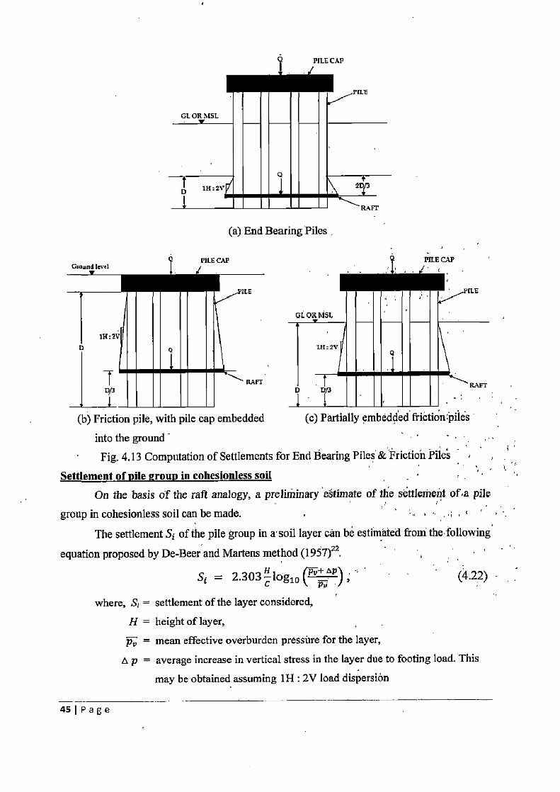
(a) End Bearing Piles ,
(b) Friction pile, with pile cap embedded (c) Partially embedded frietion:piles
into the ground Fig. 4.13 Computation of Settlements for End Bearing Piles &'Friction Pile's
Settlement of pile group in cohesionless soil On the basis of the raft analogy, a preliminary estimate of the settlement of,a pile
group in cohesionless soil can be made. " .
The settlement S of the pile group in a• soil layer can be estimated from the following
equation proposed by De-Beer and Martens method (1 97)22•
Si = 2.303 1oglo p"pu P ; (4.22)
where, S; = settlement of the layer considered, H = height of layer, p„ = mean effective overburden pressure for the layer,
A p = average increase in vertical stress in the layer due to footing load. This may be obtained assuming 111 : 2V load dispersion
45~PaBe
C = constant of compressibility, _ 1.5gc
Al' (4.23)
where, q, = average static cone penetration resistance for the layer considered. Settlement of vile group in cohesive soils
For piles in normally consolidated clays, the settlement Si is given by,
c=H p°} ap (4.24) Si — i+eolog10 pv
where, S1 = settlement of the layer considered,
H = height of layer,
pv = mean effective overburden pressure for the layer,
t p = average increase in vertical stress in the layer due to footing load. This
may be obtained assuming 1H 2V load dispersion, Cc = compression index, and,
eo = void ratio in the clay layer corresponding to the effective in-situ overburden pressure.
For piles in pre-consolidated clays, the settlement S is given by
S•
CC
i t Al') (4.25)
c 1+eo = log10giD p~
where, pc = pre-consolidated pressure of the layer considered.
From serviceability considerations, the settlement of pile group should not exceed 50
mm.
4.2.9 DESIGN OF PILE CAP
Pile cap is a structural member that ties a group of piles together. Plan dimensions of
the pile cap are decided from the spacing between the piles and their arrangement in the
group. Piles should be well arranged in a group so that the centroid of the group coincides
with the line of action of load. A clear overhang of 100 mm to 150 mm beyond the edge of
the outermost pile is given to the pile cap. The thickness of pile cap is usually governed by
the shear developed in the pile cap. Pile caps can also be designed using the truss analogy.
A clear cover of 50 mm is provided to the reinforcement in pile cap.
As shown in Fig. 4.14, the critical section for moment in the pile cap is at the face of
the pier.
The pile cap is also checked for both, one-way shear & two-way shear. The critical
section for one-way shear in the pile cap is located at a distance equal to effective depth `d'
46IPage
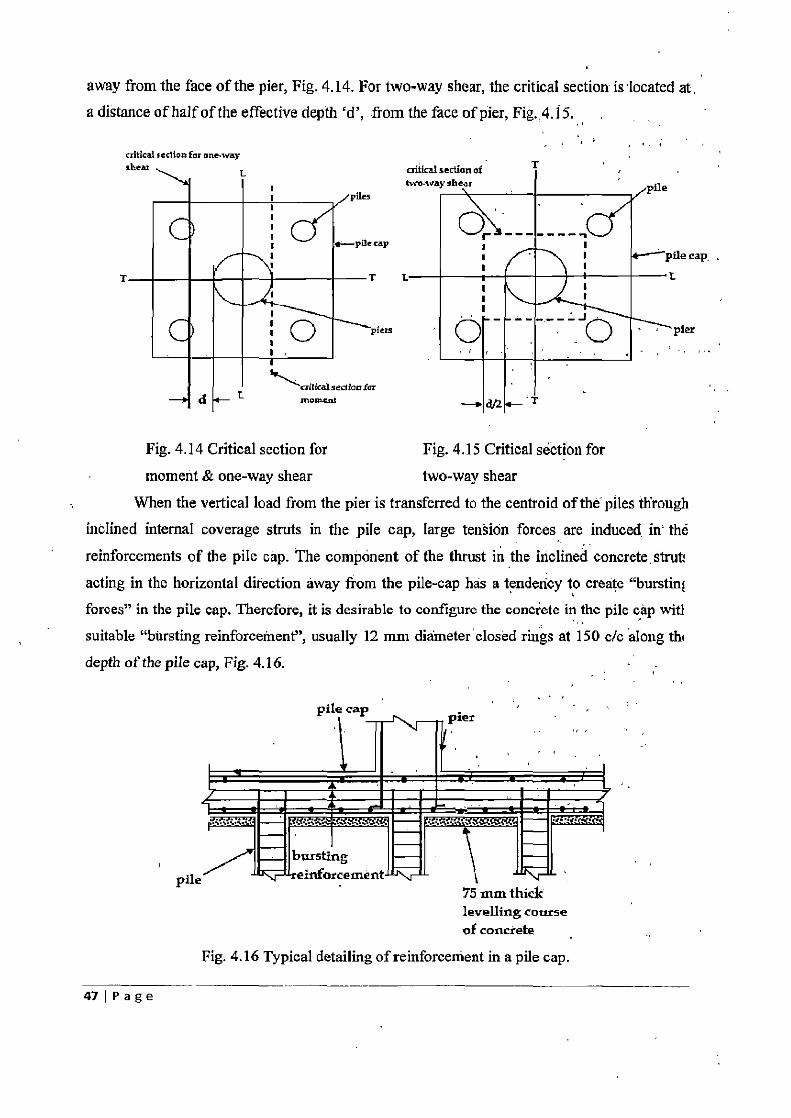
away from the face of the pier, Fig. 4.14. For two-way shear, the critical section is located at. a distance of half of the effective depth `d', from the face of pier, Fig..4.15.
`-'r ----- --~ ! 1
1
1
! 1
1 1
1
1
9L*:T9.
critical sedton for one-way shear
1 1 I 1
CI 1 O
critical section of T two-way shear
/plles
1—Pile cap
—T L—
__piers
/pne
t— pile cap, J L
pier
1 11~
`aitkMsedianfor d L moment ~y - - T
Fig. 4.14 Critical section for Fig. 4.15 Critical section for
moment & one-way shear two-way shear
When the vertical load from the pier is transferred to the centroid of the piles through
inclined internal coverage struts in the pile cap, large tension forces are induced in the
reinforcements of the pile cap. The component of the thrust in the inclined concrete. strut;
acting in the horizontal direction away from the pile-cap has a tendency to create "burstinf forces" in the pile cap. Therefore, it is desirable to configure the concrete in the pile cap wit!
suitable "bursting reinforcement", usually 12 mm diameter'closed rings at 150 c/c along thl
depth of the pile cap, Fig. 4.16.
pile cap .
75 mm thick levelling course of concrete
Fig. 4.16 Typical detailing of reinforcement in a pile cap.
pile
47 I P a g e
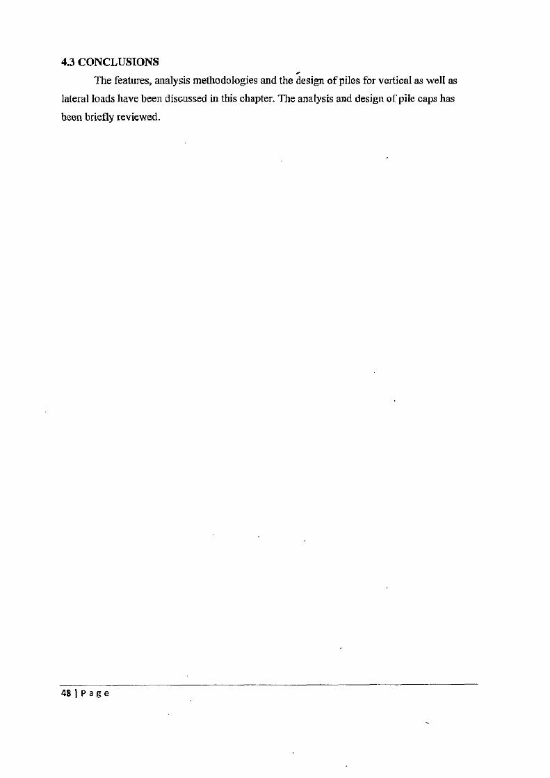
4.3 CONCLUSIONS The features, analysis methodologies and the design of piles for vertical as well as
lateral loads have been discussed in this chapter. The analysis and design of pile caps has
been briefly reviewed.
481Page
CHAPTER 5
SOFTWARE FEATURES
5.1 INTRODUCTION A software has been developed in the Visual Basic.Net platform for the analysis and
design of bridge piers and foundations. The analysis and design of both well and pile foundations is incorporated in the software. The details and features of the software along with its functions layout are presented in this Chapter. Interactive feature are incorporated in the software which
provides guidelines to the user for the input of every data. The software provides ample of
flexibility to the user for selecting suitable data.
Some of the important user friendly aspects of the software developed are as follows:
1. The analysis and design calculations are explained sequentially with the help of
appropriate diagrams
2. Alert messages are given by the software if the user misses to input the required data in
any of the form pages. 3. In case any of the analysis or design requirements are not satisfied the software will
prompt the user with appropriate alternatives.
The limitations of the software developed are as follows:
1. Simply supported spans are assumed for the superstructure
2. Only the following live load categories are included in the software: Class A and Class
AA loading
3. The functions of the software are limited only up to the analysis of the pier. Software
does not incorporate the structural design of piers. Also software can perform analysis of
only two types of piers: wall type pier and hammer-head type piers
4. Software can work out for circular well foundation, bored cast-in-situ & under-reamed
piles only.
5.2 FUNCTIONS LAYOUT OF THE SOFTWARE The tasks performed by the software are partitioned into various modules. The
computations done in each module & the functioning of the modules are presented in the form of
flow charts as explained below.
49IPage
5.2.1 SELECTION AND INPUT OF PARAMETERS USED FOR ANALYSIS AND
DESIGN OF FOUNDATIONS
Initially, the software will ask the user to select the type of foundation whose analysis and
design is to be performed. The option of pile foundations is provided for river bridge crossings
and for elevated roadways. The user will be asked to select any one type of bridge: river bridge
crossing or non-river bridge crossing. The option of well foundations is provided for river bridge
crossing. For well as well as and pile foundations in river bridge crossing, the user will be asked
to input values of maximum mean velocity of stream, High Flood Level (HFL), Low Water
Level (LWL), mean diameter of river bed particle & submerged density of soil at the site where
the proposed foundation is to be provided. The option for use of different type of material in the
pier is included in the software is included in the software. The user will be asked to input other
relevant parameters like depth of girder, span, dead load on each girder, area of superstructure,
type and width of carriageway & seismic zone, etc...
The flow chart for the preliminary dimensioning of the pier is presented in Fig. 5.1 If a
wall type pier is selected then as per the bearing spacing and plan dimensions of the bearings, the
minimum required top width and length of the pier (without cutwater) is calculated.. Software
will not perform the next stage of calculations unless the input value of top width and length of
pier (without cutwater) is greater than the minimum requirements. Later, the user is prompted to
enter the batter of the pier so as to calculate the bottom width of the pier. Length of pier cap of
walled type pier is calculated from the top length of pier. If a hammer-head type of pier is
selected by the user then the user is asked to input the diameter and height of the pier shaft'
Length of pier cap is calculated from bearing spacing and dimensions. The user will be asked to
enter the thickness of the rectangular and the tapered portion of the pier cap
50IPage
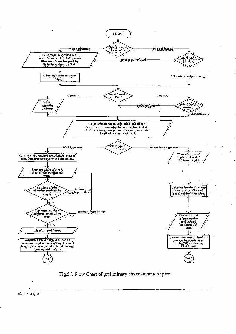
3rAin'
of tne3n,
Enter depth ofgirdcr:'spnni; leaalood'on each _: ginIcr; arar of urkSruetuv. Sclre! lypc afci:isa loading. sciamic zone & typeorearitugc way, enter,
en gEb of ca riac *&v widil,
pier
Pier aced
Fig.5.1 Flow Chart of preliminary dimensioning of pier
511Page
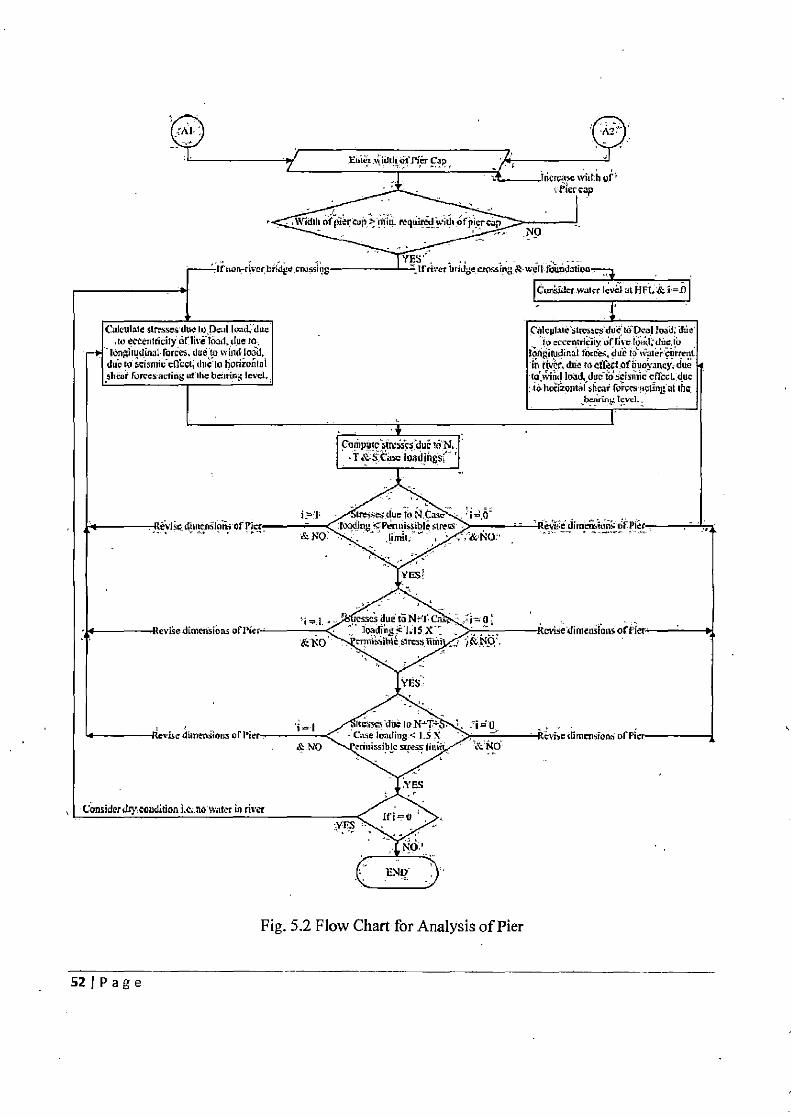
Fig. 5.2 Flow Chart for Analysis of Pier
S2 I P a g e
5.2.2 ANALYSIS OF PIER The flow chart for the analysis of the pier is presented in Fig. 5.2. After deciding the
preliminary dimensions of pier and pier cap, the software will perform the analysis of pier for the
various forces acting on the pier. For both well and pile foundations in river bridge crossing, the
pier is analysed for flood condition i.e. water level is at HFL. Stresses for various types of forces acting on pier due to dead load on pier, eccentric live load, longitudinal forces, water current in river, buoyant force, wind load, seismic force and shear forces at the bearings are computed.
These loads are categorized into three loading categories: Normal (N) Case, Temperature (T) Case & Seismic (S) Case. Stresses, in pier due to N Case, T Case and S Case loading are
computed separately. Subsequently, the resultant stresses in the pier due to- the following load
combinations are calculated: N case, N+T Case, N+T+S 'case. These resultant stresses are compared with the permissible limits. If the stresses are within the permissible limits, the pier is
safe and the pier will be analyzed next for no water condition. However if the resultant stresses exceed the permissible limit, then the software will direct the user to a page where the pier will
be redesigned in order to withstand the stresses safely.
5.2.3 ESTIMATION OF SCOUR DEPTH FOR FOUNDATION. DESIGN
For both well and pile foundations in river-bridge crossings, the scour depth is required to
be calculated for determining the founding levels. The flow chart for calculation of maximum
scour depth is shown in Fig. 5.3.
To ensure a sufficient margin of safety in the scour depth calculations, the software multiplies the design discharge by a flat value of 1.30 to get the discharge for calculation of the
normal depth of scour. The software calculates the normal scour depth using two formulae: formula suggested in IRC: 78-20008 & Lacey's formula.
Linear water-way in calculated form the equation L = 4.83J. Knowing the linear,
water-way L, Db is calculated. The silt factor in both the equation is taken as 1.76J , where
dm is the median size of the bed sediments, in mm. The higher of the two values of the normal scour depth is used for calculating the
maximum scour depth. The normal scour depth is multiplied with two to get the of maximum scour depth at the nose of the pier.
531Page
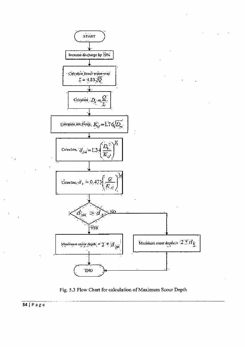
START
Increase dstharge by I
Calculate linear i*er-way
- o:
ec!ILifit:;t k>='f7q
f±_ CUlCU1LIIt,'d. ;=134 Jcj
Maxintuin scMirdejnli *L MaxiththU scuur:deplhc
Fig. 5.3 Flow Chart for calculation of Maximum Scour Depth
54 1 P age
5.2.4 ANALYSIS AND DESIGN OF WELL FOUNDATION The analysis and design of well foundation follows the designing of the pier. The user is
prompted to select the pieliminary dimensions of the ell based on empirical rules.
5.2.4.1 ANALYSIS OF WELL FOUNDATION The resistance of soil surrounding the well foundation is determined in its elastic state
and at ultimate loads to check whether the soil will be able to resist the force and moments
transferred by the well foundation. The flow chart for calculation of soil resistance using elastic theory is presented in Fig.
5.4. The flow chart for calculation of soil resistance at ultimate loads is presented in Fig. 5.5.
551Page
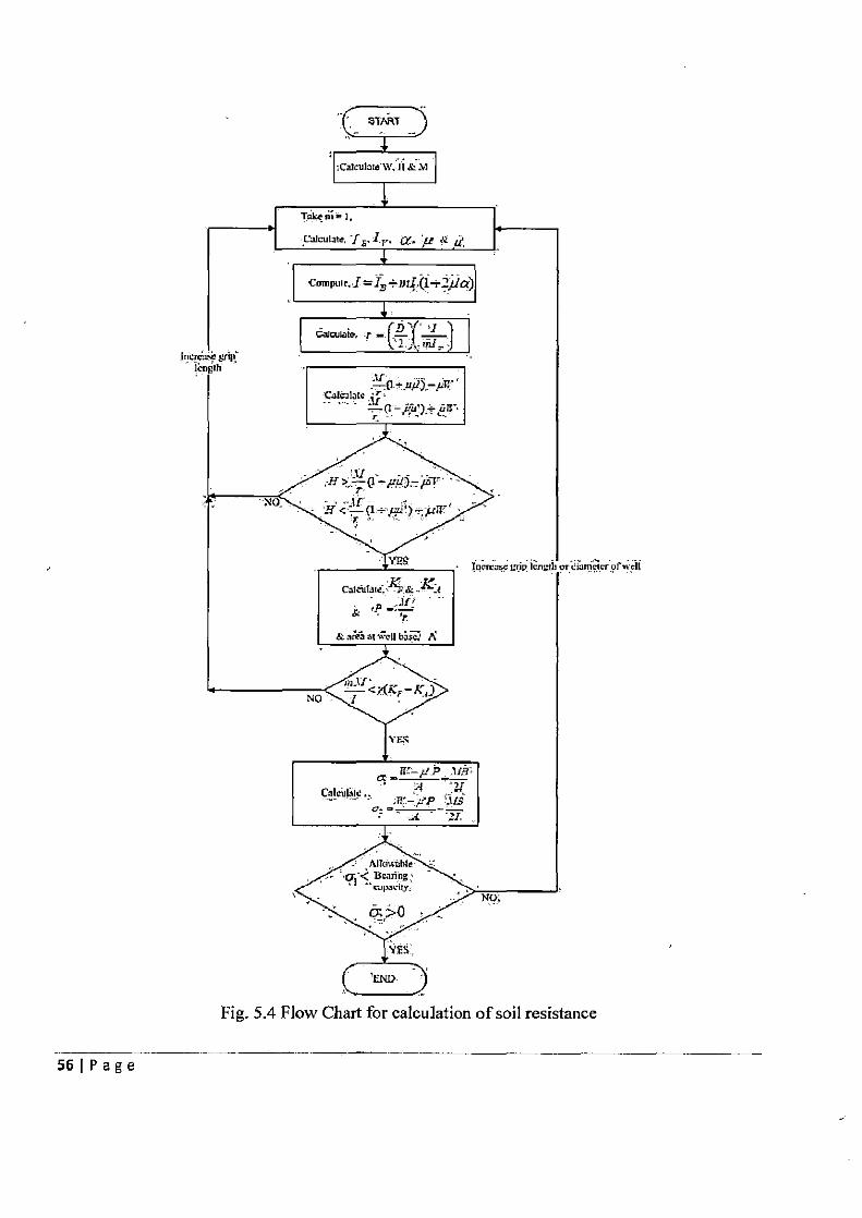
Fig. 5.4 Flow Chart for calculation of soil resistance
56 j P a g e
5.2.4.2 STRUCTURAL DESIGN OF WELL
Once the safety of the selected preliminary size of the well has been established in the
elastic state and at ultimate loads, the structural design of the following components of the well
is performed next by the software: Bottom plug (check on thickness provided), well curb,
steining and well cap. The design aspects for these components have been explained in detail in
an earlier chapter. The flow charts for the structural design of well curb, steining and well cap
are presented in Figs. 5.6,5.7 and 5.8 respectively.
57IPage
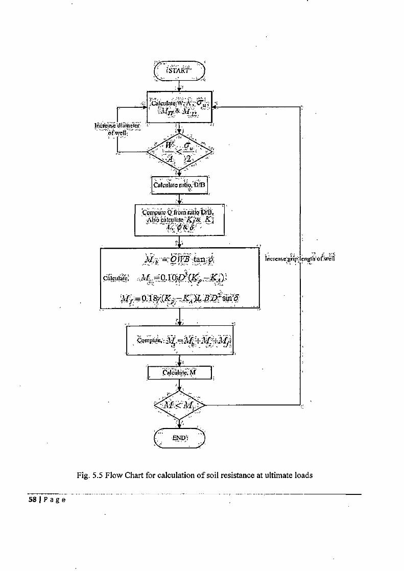
SLART
#1 Ca1culate,W,A; C ; c
FTCP diathiier 'ofweIl - -
Calvdato rn1o,din
tornpTut; Qtionir&dio bIB. Also cMculate Kp
øM -
i - tiEE
0.1 187(K2 K 4
4.
Fig. 5.5 Flow Chart for calculation of soil resistance at ultimate loads
58 1 P age
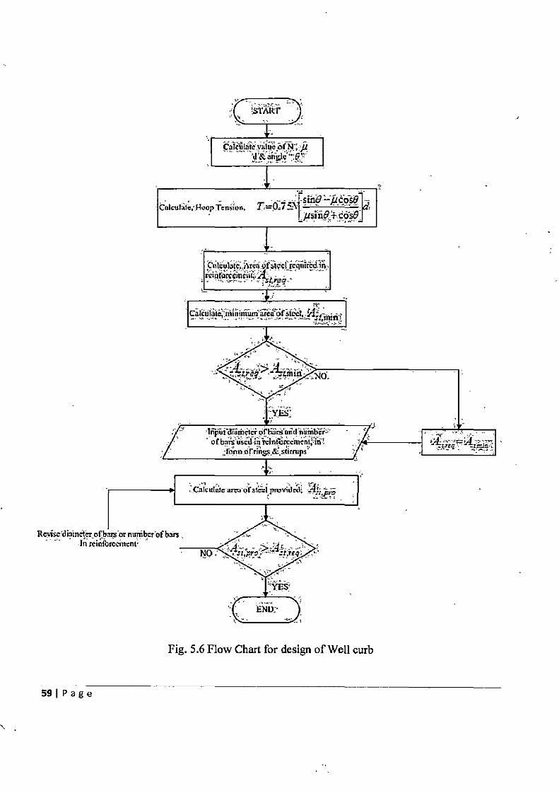
Fig. 5.6 Flow Chart for design of Well curb
Resise diainaier of t In reiaf
59 I Page
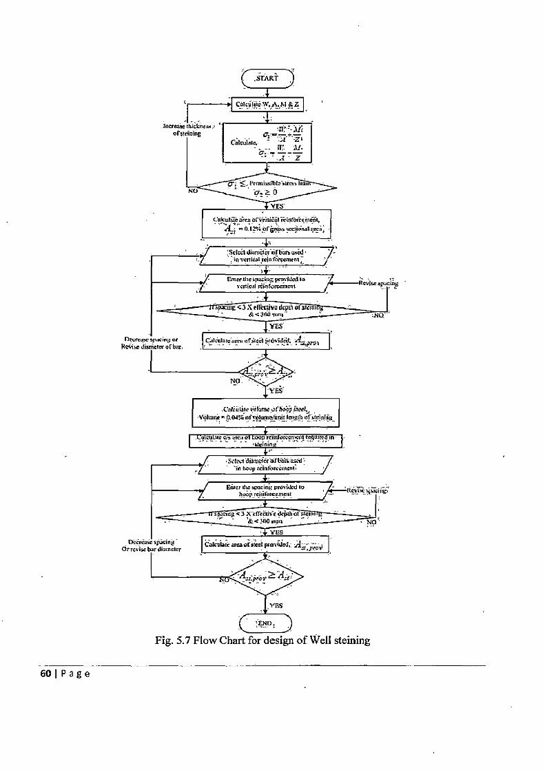
START
Catcuhdc,
PermSi,kr4rcn
ii a 0
c*ureoreHieilnroreneit, o.n%0rgr%,cc1iona1arca,
Sckcl diamêl W.I Sb mid inycflktwjpSejcantn;
Enttrflic spaéln provided in voilical ,sn(orccmcnt
orstcèl ,rOt%
,ciliThire*Iümcufhoô, eel, Yolutnt 0 64o I,flOIOm&IInII idfl3,I1 ofsieinlmg
atmnol hoop - - tc1nin
ScIec1ihiâsetero1biiüsnJt imi hoop reimiroretnest. -
Erqr the ipadng provi.Jcd to - ----- 4 h.0 reititorcemetmi
paciavc3 X £iThclncdcpahoI sleinu &<300.ifli
YES
&Iiiaic areose1 prnxiied,-. Ay;j
44prov ~ 4it
ES
'ZNP
Fig. 5.7 Flow Chart for design of Well steining
60 1 P a g e
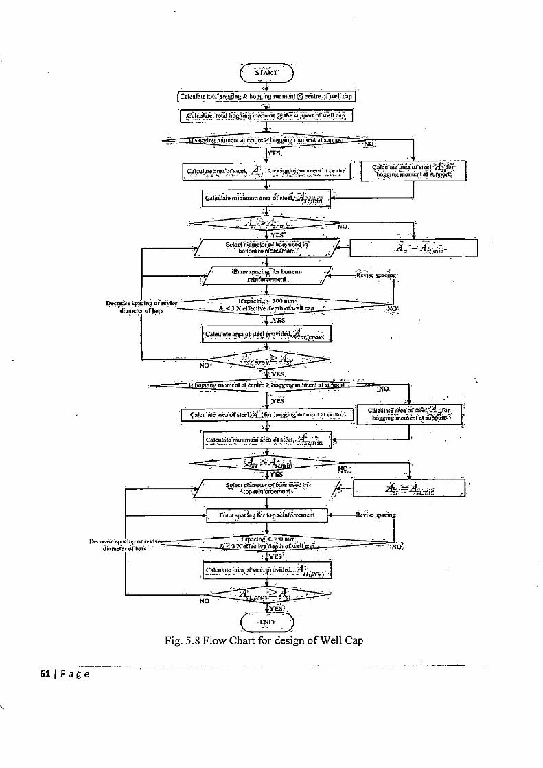
Fig. 5.8 Flow Chart for design of Well Cap
61IPage
5.2.5 ANALYSIS AND DESIGN OF PILE FOUNDATION
Before proceeding to the analysis of pile foundation, the software will prompt the user to
supply details of the sub-soil investigations. The user will be required to input details of the
numbers, the type and the engineering properties of the soil layers at the site where the pile
foundation is to be constructed. Particularly, care will be required to enter the relevant properties
of cohesive soils and the user will be required to make a distinction between pre-consolidated
and normally consolidated clays. The flow chart for soil details is show in Fig. 5.9. The software
will first run the loop to enter details of soil layers, and subsequently, the user will be asked to
enter details about the first layer. User will be asked to enter the height of first layers, density of
soil & type of soil. If the soil is sandy, then the user will be asked to enter the angle of internal
friction (0) and the average cone resistance of the soil layer (q0). If soil is clay then software will
ask user to enter the undrained cohesion of soil (c„) and the compression index of clay. Further,
the user will be asked to select the type of clay. If the clay is pre-consolidated, then pre-
consolidation pressure will have to be entered. Similarly, the loop will run again so as to enable
the user to enter the details of next soil layer. The loop will be terminated when details of all the
layers are entered.
62 I P a g e
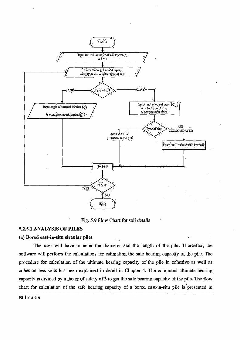
Fig. 5.9 Flow Chart for soil details
5.2.5.1 ANALYSIS OF PILES (a) Bored cast-in-situ circular piles
The user will have to enter the diameter and the length of the pile. Thereafter, the
software will perform the calculations for estimating the safe bearing capacity of the pile. The
procedure for calculation of the ultimate bearing capacity of the pile in cohesive as well as cohesion less soils has been explained in detail in Chapter 4. The computed ultimate bearing
capacity is divided by a factor of safety of 3 to get the safe bearing capacity of the pile. The flow chart for calculation of the safe bearing capacity of a bored cast-in-situ pile is presented in
63 I P a g e
Fig.5.10.
(b) Under-reamed piles
The user will be asked to select the diameter of pile stem and the number of under-reams
on each pile. For the selected diameter of the pile stem, the length of pile specified in Table 1 of
IS: 2911 (Part III) — 19804 is noted. This pile length is stored in "L". If the number of under-
reams selected for the pile is less than or equal to two, then for the user specified diameter,
number of under-reams & length "L", the safe vertical load for the under-reamed pile is read
from Table I of IS: 2911(Part III) — 19804. However, if the number of under-reams specidified
by the user exceeds two, then the safe vertical load for the pile is extrapolated with the help of
the incremental values given in Table I of IS:2911 (Part III) — 19804.
The procedure for obtaining the safe vertical load of an under-reamed pile is presented in
the flow chart in Fig. 5.11.
641 Page
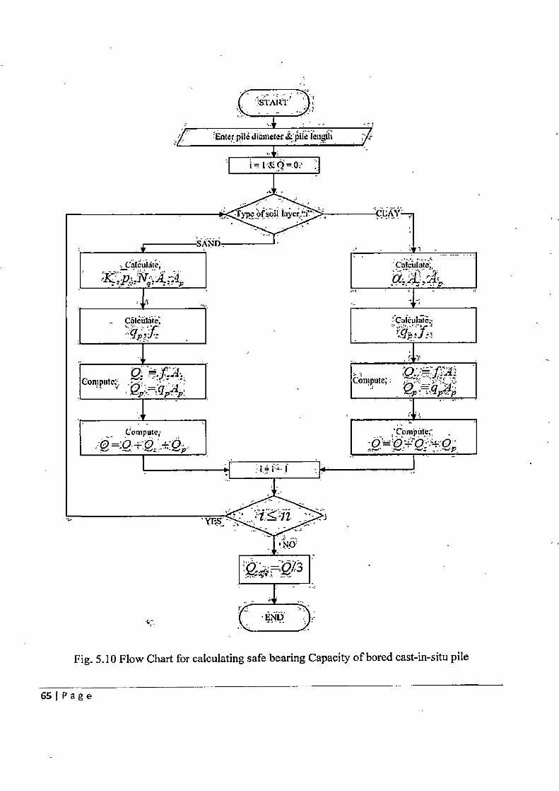
Fig. 5.10 Flow Chart for calculating safe bearing Capacity of bored cast-in-situ pile
65 j P a g e
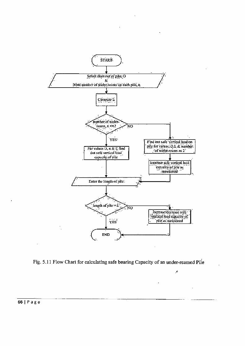
Fig. 5.11 Flow Chart for calculating safe bearing Capacity of an under-reamed Pile
66 I P a g e
5.2.5.2 SAFE BEARING CAPACITY OF PILE GROUP
After calculating the single pile capacity, the safe bearing capacity of the pile group is
calculated.
(a) Pile groups with bored cast-in-situ piles
The software will calculate the vertical load acting on the foundation. The pile
dimensions are then entered by the user in software. As discussed in the previous section, the
software will calculate the ultimate bearing capacity of a-single pile and from it the safe bearing
capacity of the pile. Dividing the total vertical load on the foundation by the safe bearing
capacity of one pile will give the total number of piles required in the foundation. The software
will ask the user to enter the total number of piles. The number of piles provided will be accepted
only if it is greater than total number of piles required. For analysis, the pile group is considered
to act as a deep footing in soil. The software will then run the loop file to calculate pile group
capacity. The software will start with soil layer 1. If layer 1 is sand then Qs & Q, will be
calculated as per the formulae of sand, while if it is clay then the formulae of clay will be used to
calculate values of QS & Q,. The loop will run again and calculate Qs & Qp for the second layer,
as per the soil type. In this manner the software will calculate the value of Qs & QP for each Iayer
of the soil. Finally, Qs & Qp for all the soil layers are added together to obtain the value of Qg;.
Qg,safe is obtained by dividing Qg by 3. If Qg is more than the total number of piles provided *
ultimate bearing capacity of each pile (Q) / 3, then Q8,sare will be equal, to the total number of
piles provided * ultimate bearing capacity of each pile (Q) / 3. ,
The values of Qg,safe finally obtained is the safe bearing capacity of the pile group. The
flow chart for calculating the safe bearing capacity of pile groups made of bored cast-in-situ
circular piles is presented in Fig. 5.12
(b) For under-reamed piles
The flow chart of Fig. 5.13 explains the complete procedure to compute safe bearing
capacity of under-reamed pile. User is required to enter diameter of pile stem, number of under-
reams on each pile & spacing between piles. Diameter of under-ream is taken as 2.5 times the
diameter of pile stem. If the spacing between piles is less than two times the. under-ream
diameter, then the safe bearing capacity of pile group is taken as 90% of safe bearing capacity of
single pile X number of piles in foundation. While if spacing is more than or equals to two times
the under-ream diameter, then the safe bearing capacity of pile group is taken as safe bearing
67 I P a g e
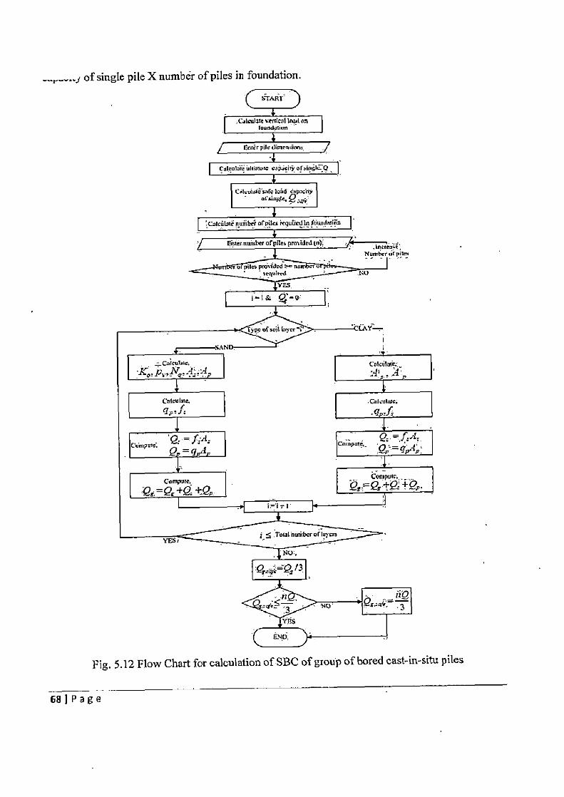
-j of single pile X number of piles in foundation.
Fig. 5.12 Flow Chart for calculation of SBC of group of bored cast-in-situ piles
68 I P a g e
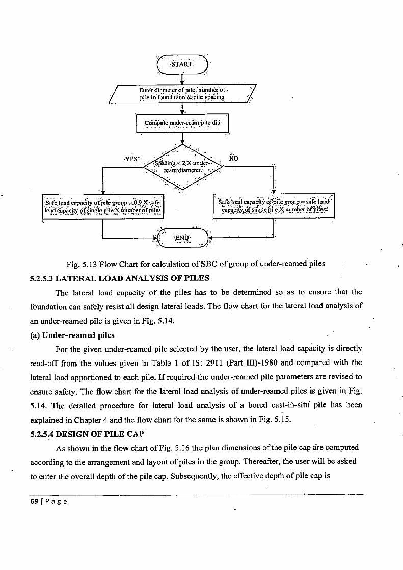
,START_
Cdni uie under-redm pile di3
yp~r No
Stc.IQadcapatyofpilguup 09Xaife ~SuletopJ.^upaatyofp~lc~~uup.. yifeloai load acfy ofsingle pt le WX number orpiles c~anry of 3mgle,pile apumber of piles
Fig. 5.13 Flow Chart for calculation of SBC of group of under-reamed piles
5.2.5.3 LATERAL LOAD ANALYSIS OF PILES The lateral load capacity of the piles has to be determined so as to ensure that the
foundation can safely resist all design lateral loads. The flow chart for the lateral load analysis of
an under-reamed pile is given in Fig. 5.14.
(a) Under-reamed piles For the given under-reamed pile selected by the user, the lateral load capacity is directly
read-off from the values given in Table 1 of IS: 2911 (Part III)-1980 and compared with the
lateral load apportioned to each pile. If required the under-reamed pile parameters are revised to
ensure safety. The flow chart for the lateral load analysis of under-reamed piles is given in Fig.
5.14. The detailed procedure for lateral load analysis of a bored cast-in-situ pile has been
explained in Chapter 4 and the flow chart for the same is shown in Fig. 5.15.
5.2.5.4 DESIGN OF PILE CAP As shown in the flow chart of Fig. 5.16 the plan dimensions of the pile cap are computed
according to the arrangement and layout of piles in the group. Thereafter, the user will be asked
to enter the overall depth of the pile cap. Subsequently, the effective depth of pile cap is
69 Page
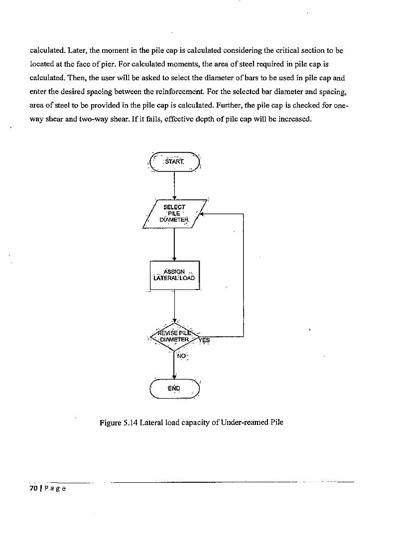
calculated. Later, the moment in the pile cap is calculated considering the critical section to be
located at the face of pier. For calculated moments, the area of steel required in pile cap is
calculated. Then, the user will be asked to select the diameter of bars to be used in pile cap and
enter the desired spacing between the reinforcement. For the selected bar diameter and spacing,
area of steel to be provided in the pile cap is calculated. Further, the pile cap is checked for one-
way shear and two-way shear. If it fails, effective depth of pile cap will be increased.
Figure 5.14 Lateral load capacity of Under-reamed Pile
70 Page
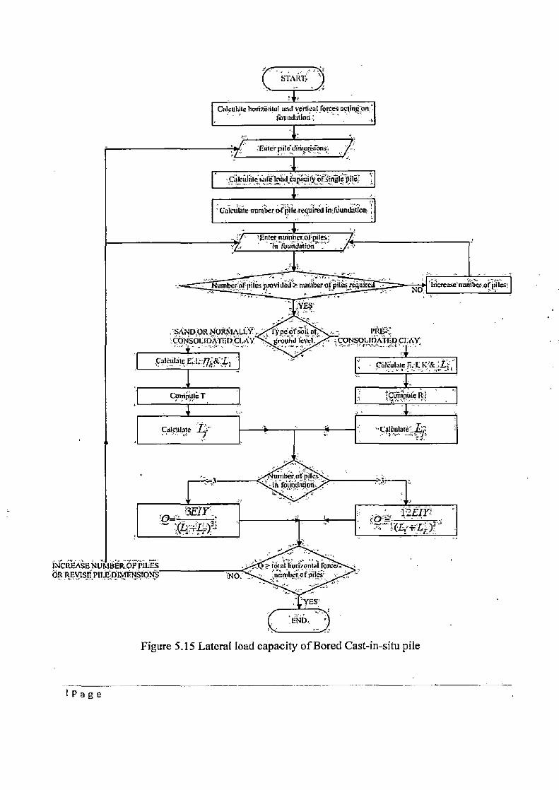
Figure 5.15 Lateral load capacity of Bored Cast-in-situ pile
I Page
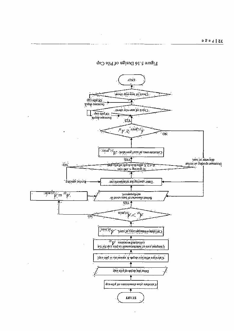
a8edIZL
duo aIMdJo u2tsOQ 9T'S a.znSi j
5.3 CONCLUSION
The features of the software developed in theVB.Net platform for the analysis and design
of bridge sub-structure have been explained with relevant flow charts in this chapter. Some of the
interactive features of the program which facilitate the work of the user have been highlighted.
73IPage
CHAPTER 6
RESULTS AND DISCUSSION 6.1 INTRODUCTION
The features & the functioning of various modules of the software developed for analysis and design of bridge substructure has been discussed in the previous chapter. To illustrate the
practical application of the software, analysis and design of the well foundation and pile foundation is performed for the assumed parameters. The long hand calculation's of the problem will be done, which are compared with the results of software, to verify the output of the software developed in the thesis work.
6.2 PROBLEM ON WELL FOUNDATION
The analysis of the well foundation and design of various components of well are being
performed. The details required for the analysis and design of well foundation are given below: DETAILS REGARDING BRIDGE SUPERSTRUCTURE
➢ Dead load on each span: 1500 kN ➢ Depth of simply supported girder: 2 m
➢ Span of simply supported girder: 16 m
> Type of Carriage way: Two lane carriage way
> Clear carriage way width: 7.5 m
> Area of bridge superstructure: 70 m2 > Type of live load acting on bridge: Class A loading
BEARING DETAILS
➢ Type of bearing used in bridge: Sliding bearings of Teflon on Stainless Steel
➢ Centre-to-Centre distance between bearings along longitudinal axis of bridge (Si): 900
➢ Centre-to-Centre distance between bearings along transverse axis of bridge (S2): 5500
mm
➢ dimension of bearing along longitudinal axis of bridge: 300 mm
➢ dimension of bearing along transverse axis of bridge: 400 mm OTHER DETAILS
> Maximum mean velocity of stream: 4 m/sec > Maximum discharge of stream: 4500 m3/sec
74IPage
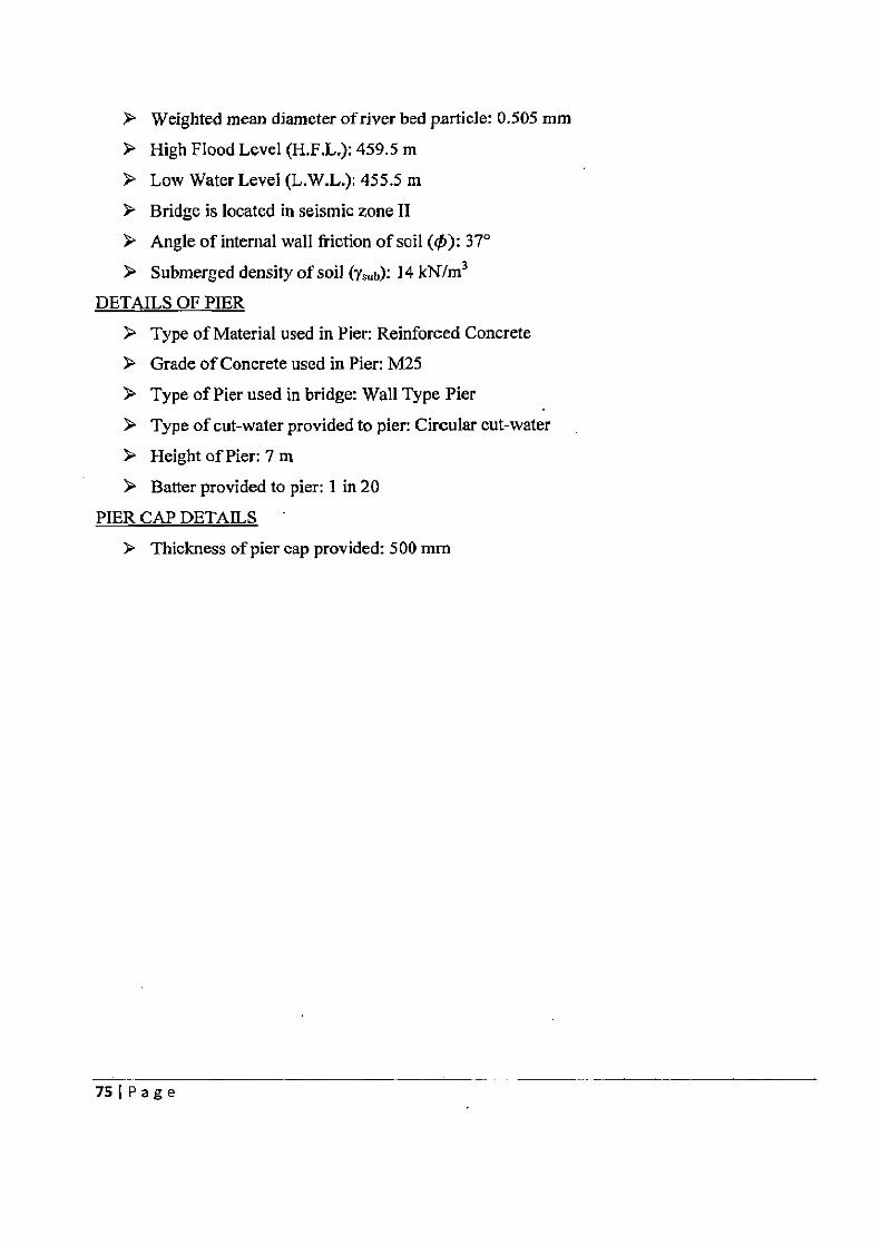
➢ Weighted mean diameter of river bed particle: 0.505 mm
➢ High Flood Level (H.F.L.): 459.5 m
➢ Low Water Level (L.W.L.): 455.5 in
> Bridge is located in seismic zone II > Angle of internal wall friction of soil (t): 370
> Submerged density of soil (ys„b): 14 kN/m3
DETAILS OF PIER
> Type of Material used in Pier: Reinforced Concrete > Grade of Concrete used in Pier: M25
➢ Type of Pier used in bridge: Wall Type Pier
➢ Type of cut-water provided to pier: Circular cut-water
> Height of Pier: 7 m > Batter provided to pier: I in 20
PIER CAP DETAILS '
> Thickness of pier cap provided: 500 mm
75 1 P a g e
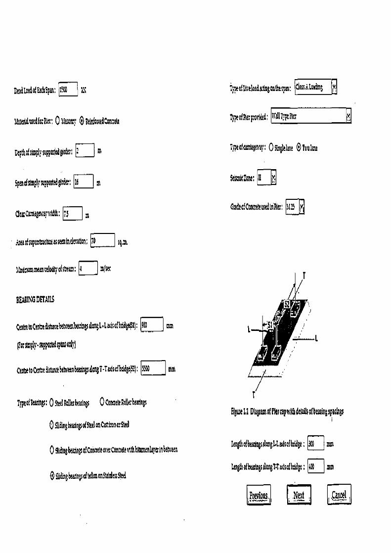
DtadloadolEdspan: t~0 r\
Tyeoflscektdb6nonthepan: C1ass~ ___
1lsttdalnsed(fltt; O Joy 0 FtIth cedCotu tR 1l ptothcporidd, 1T~IT,ptPle t!!
DpthQffty suppartd rdtt; : m T}ptoltttlaglnay, 0 ss elant 0 T OIau
5panafslmp1ysuppodtddtdtr, 16
Clta CaMagtnay ttldth: ;.S m
?maosup~s~ktntassttniueleratlon; 6 sq,~
tilmdmummtanvdodtv ofstnam: 4 J%f set
BEIFING DETAILS
CtntreroCts~edistanrebehtetnbtangsatoogl laaisa(bridg1l; El m
(foromply suppottadspansotVpl
CtntttoCtntdift!nu ttn'tnbcartngsaloT•Taaisaibddgs), S3° mm
Tppt of !ea~iegs: O Ss Rolltr bearings 0 Canatte Rolttr btulr3ss
O Slidingbw!ngsotStttlonCastlonor<.ttrl
09ltdtngbSng o!CornttavttConrtstuithbltvntnla}~rinhtPrttn
9(din gbeaiasof ttonontasnitssSSI
41srolcon: >i
GradcafConathuedIithtr; 115 yi
Elute11 DkgnantotrkrcapuithdelagsQIkasiugspacings
ltnghofhtasin8s4anJ4a+isolbddt: a mm
kngthafhtasiingsalanT•TasisoIbddgt; nog mm
iPtflvious ; Next ,f, ance1
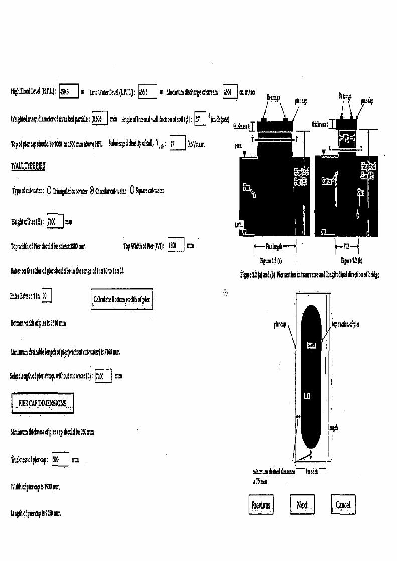
aMaJM1dsshtddwma
HighfoodteseL(RED: 4393 m thsq'atalS(LL): 4133 m Admmdfsdsaglofstrlam: ~'9U nimlw
lYll dldmleltdlmttaoffivtbdptldt: mm ;ngleaflntrtnalnaRfstctlonefsofli I: N t (Indco) k
Tapofpiltcapshoddbli000 io1~D ma6osYi~t 9ubmaglddStpoU II, Y th : 17 0
WALLT?EPIER
T}ptofatsrattr: 0 Ttiadgsd,NFxatlr 0 Cimlarcntxata Q 9guaselotsrater
Keighto.°Aiu(H): il00 mm
Topgidtltoffiusiwaldbeaticastls00m Topil9dthofhe (it): 1S'D mnt
ripe 1.2 (a) 6gero13@) Batter on the sides of pie: shod be in the range oil in 10 to 1 in 13. Fipie L2 (a) and (b) ha wtion in Iransvase and WngihdGial dkalion of btidg!
Entt&tt:IiA ?d Cahniate Bolton nidlh of pkr
Bottom width of pier is 210 mm
6Bnin duitoUe1qhofpier(aithotaiMcW)U®IIUn
Saltt1en*ha( pie altop 1FlWtNtsrah:(L): ilpp mm
I p1ERCAPDIMENSIONS
lhrdmomtld& ssofpiacapshoddb!230amt
?'nkbissofpilrcp: mm
119 dth of p It cap is 1910 mxn
tangtit of pier tap 1s 9050 mm li~ Next . .Cancel
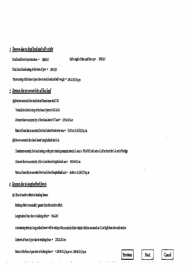
1, Stresses due to dead food cud self fl?iRhi
Deadloadf omSupeshuthtnt a 3pppk\
clhreihtof2kraad Pier cap 3590k\
Total disectlaadatingattha base ofpiar 6593k~
Shtss ating at the base of pit: due to dead load S self urd ght a 1S9. ke Js q m
t Stresses due to eccoubicilr. of live load
(a) Doc toecccutik live load abootTransstssc J5T•T
Veeical ltut 1 oad ac tlng at the base of pier I s 56334 kN
tlomcnduetoncntncit'aflireloadaboutT.rSsa 179s1kX•m
St:assat base the taetteahic live load about hanse.saaustl 5350or135Sk\Jsq.oa
(b( Due to Hcanhit live load aboot Lougil ndiaal axis 4L
1(mdnsumchantisliraloadactingontlupiercaatlngmomentabout41a+dsIs 31.9k aitd & 1A5 mTrouttha1•ladsofbridge.
Uomeatduatoc¢cenhiatrof live load a' utlo*dinala+asa 96S.96kX•m
Sttssat base the totcctnhiclire Load about longltdinala~ds'6.6Oor•SS6k1Jsq.on
3, Stresses due to kuzuudinQllorces
(a) Due tohadiseelfostorbaakingfoxes:
ralang effect islneatiabl7gt& rthantheuactiratffot
longiNdinalkca due to Ira bneffot' 19k1k\
Constdahngtnst the longiNdlealfoxewlllbe tingat the cenholdof the Alouddtisasnute&as Urn lrigltrom the ooadsutace
i10 tentalbauafpierdatetobraking(axe a 11S.0m
Sttessat the base of pier due to braking (axe I239.%kNJsqmor•:39,S6kN/sqm Previous j Next . Cancel
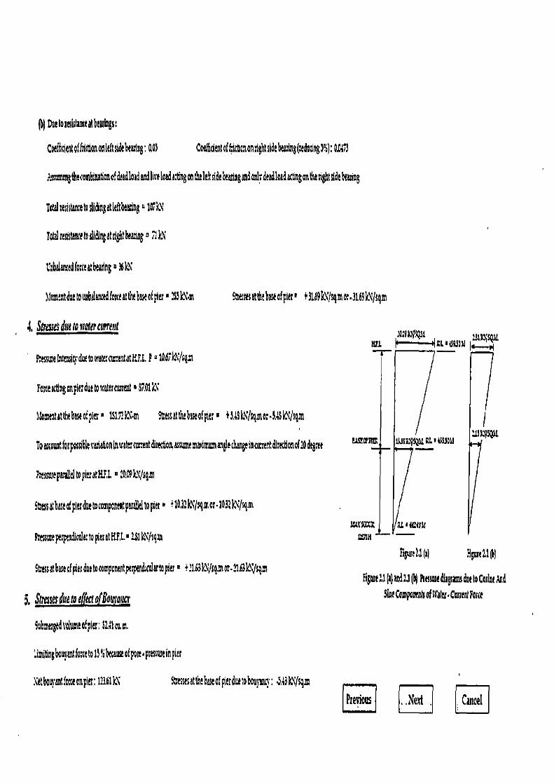
Fi6urt 2.1(11 Hgue 21 I)
Figtue.l(a)aed2.1(ii) Psessmedlrgrams due toCoslneM
Slag Components of R•atu • Cmrenl Farce
) Doeioreutanteatbudngs.
Caftldtntoffsitbononitltside adng: 001 Coelfidentof#ttcnontlghtsideWng(tadodng3%): OAI;1
:.ssnmistgtheecombtaeoofdead1aadandIireloadagingontha1t sidebeanngandonlydeadloadact non t tightsidetiming
iorol tehstantero sli&n$atkftbea7ng ■ 101k,
TodrostwetodidingenioNa n■ UN
Uthalancedfo taatbtating a 36k\
lomentdottoonbelancedforaeattitehRofpiu ■ ?13kN•m
Stemsetthebaseofpter■ +3169k1/gmor.31.6k1Jqm
4, Soo due to water cwrent arIX143t Nil
Stessatbasedpterdoew ompont pam>klropier ■ 4103:kNJsgmor•1a39.'/cqm
Pmsme pepeadktk to pier at H.F,I. ■ 231 k\ Jsgm
Stressatbasecf pier doe tocomponentpaspendimlartopier' +21b3kVJsq.n or•21.61 sqa
5, Smamsdueto effect o!Botremtgv
Sabmetgedt'olumeof pier ; Siltau,m
limitingbcosantfarceto 15% W aose of pole.pttssnreinpier
Ressme Intenit3• due to reattrnn;entatFJ,L p ° 1047 kXf sg,m
bite attingon pie; due towateroametst '87.01 k\
IWnseatat the basaof pie; • 1515! .in Saessat the baseof pit; ■ +5.14k1lsqmor•3.13k\Jsgm
To attoontforpossiblesanatoninuate:turrentdre to;assomemaamsnangleduneinmrrentdirdonof?Odegne
Presssuept idtopeutlY.1. ° 1 O9k'Q ni
Xetbci intforceonpiet;113.61k1 Sarssesatt ebsaatpetduetoboo}ants: ~,+3k\Jsgm
Ptecious .Next , Cancel
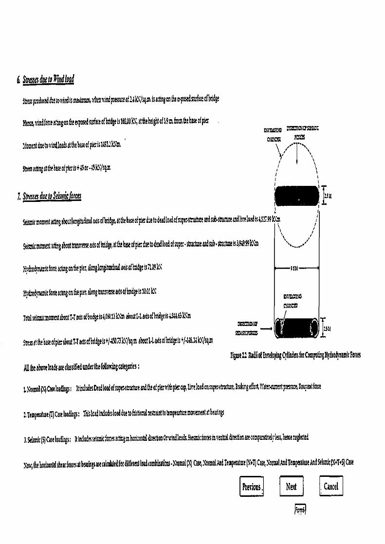
6. Stresses due to D rttd load
5b:esspraducedd2tonindisma dmun6 u'htnwindpressuteo,42W/ gmisattingontht ewposedsmfaceof bridge
Hentt, uind force &ring an the e> osed surface of bridge is 16£Od ktl, at the helghl of 5.9 a froai the base of pies ~~~ onastc~csoss¢c
nZ alomentduetonin4loadsatthebasaofpleris1d97:kNm \ "" 1 ••,
sttessacungategbaseof Fluls+d3o:-W/sgm ,
1 Shesses due to Seisrtritfrrres is 9 Ii
SeismumomentMgaboutloagitudinaladsaf bridge, at the base of pier due to deadIW of super stttdne and sub. souttuttandliveloadisa•52.99kxm
I l Feisrdcmoul7latgngaboutt;ans'etoeisofbnidge,att ebaseofpicduetodeadloadof a e;•st:uctmeandsub.sGuMseis3,%9.99k\m I •,-,-,; '
Hti drodtrtamdc fort gong on me pk r, along langitundi nai as of badge i 11, 9lX
hl'drod}namlc force &tgon the pier, dong ttarsretu As of bridge is 10.0.1 LX
TotlstlsmlcmomentahoutTdadcofbndgels&&13k1'm about 4t fsofbndgeis;,St1.e43k'm
Suessatthe base of pit aboutl•1&isofbrldgeis+/41O73kX/sgmaboutLLadsof bridge is4(-14th k'igm
M w . x,u
\` "Da
Figmt I.: Radii of Em'eIoplog Cylfndtts for Compuliag H} tod}namic !orsts
All the above loads ate classified uaderthefogon gcategoties;
t\mmal(N7Caseloadings: Itincludes Dead toad of sup erscixhueW the o:pierenthpie cap, lire load ansuper4thxtuse,9raldng effort tl'aer rentpnssu e,Sourantforce
:,Ttmperalme( Cue loadings; Tnislaadtrcludesload due toftictanalestaintroMmpeutuemotieutantatbearings
3, Selsmic(S)Case loadings: Ittntludtssetsnicfoms actinginho imnW dittctlonOndndloadLStesndcforcesinretitcal direction artcomparatlrdrless,hencenegieded
xow,thehodwnlal shear fouesat bearings are almWtdferd f treul loadcombinatiom•Notnul Cue, Normal AidTemperature Xs1) Case, NotmalAndTempeaatueAndStlia*(N T'S) Cast
l§evious ; Next Cancel
R
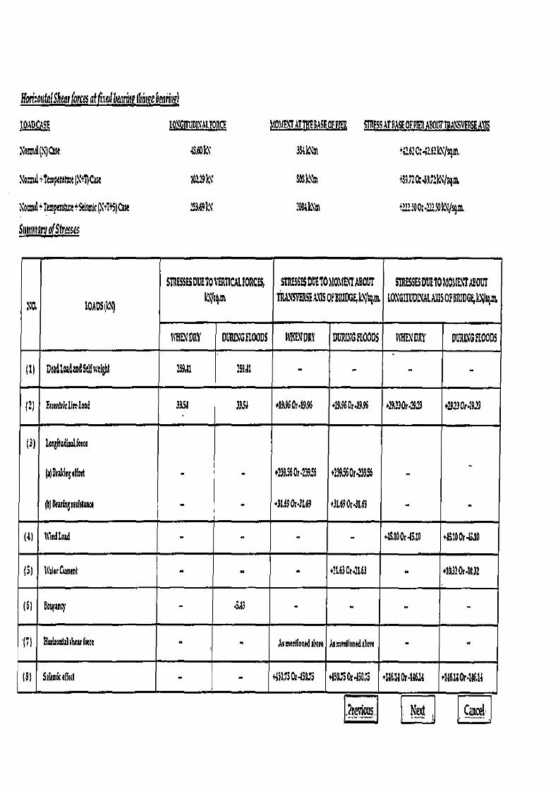
gorconfal Shea, forces atfia'edbeathj Ihi&ebeann 1
10AD A E 1o\G1TVOINAL1DRCf M0'PT4THtMMSf0EP1ER STRESS T SFO£P1E11IBOLT1Ra1S1fNSEh11S
%oW(\jwq 4601N 3Slk\1n P9:.61Co462kNhgl
NoS +temptanutN+flCau 10239k\ SOSk1m .fl Ct 49.72k1sqm
NoS+Temptrab t%smlc(\+T}S)Cue .93,69k\' 20DikNm +22210Ot.212.dk\/qL
Suntnt ivy of Stresses
X0, tOADS L\)
STRESSES DUTOYBR11CA1.20RCB6,
I`~Iq'm
SIRf6SESD1'MTO COMET ABOUT IIMNSVIRS!L\]SOFBRIDGF,km
SMTMESSESDUTOMOIt7ABWUT 101GII1D1YAt SOFBR1D6iS
11'aDRY DIJRL\'GEIOODS M*MDRY DURING FLOODS MONDRY D11RL LOODS
(1) D1D4alidStffwIghI 2S9d1 16941 - - - -
(2) frtanlrPrllrrlord 3359 3353 d99601•1996 •]9.9fi0r•19,96 +29230r•2923 s11230r.9.23
(3) log1ludio2llmra
(i)Bnkingt((ott
())Indn3ndaz&e
-
-
-
-
t239,56Or.23936
+3G690r4Ld9
t23936Orti3956
+36690x,3169
-
- -
(4) 11indLozd - - - - +15100x49,10 *19I100r4S30
(5) WrlerCuntnl - - • •11.630t.2163 +1Od20e.10,32
(7) Hatitonldiheu(ate - - ASmtnOonedebore Asmenlionedalm -
(SI Sohodretlatl - - 4i9, 3Or-ISO, i .450.75Ordi0 a +146,1l0r1961d e1161a0r•116.14
ER C~Ifi1' 1
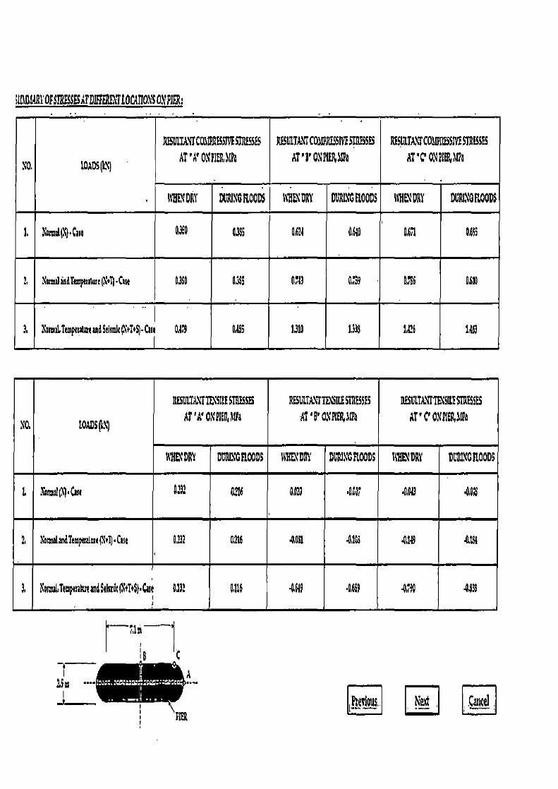
; nBtR1'OFSTRESSEATDIf zR11'TIOG1T10S01'PIER:
NO. SOADSp
ASUITMU a1P.RPSSIYESTRESES AT'A' 01'PIUUIPa
BESIANKC03121 SSW STR 5SES AT'B' ODPAIIPa
RISLITA.TC0,05SIVESTRESSES AT'C' 01PIER,11Pa
IYHL1 DRY DL1UXG ROODS 141LX DRY DDALIG @L0ODS li 1LN DRY DLTIIIGaOODS
1, \mmil►1)•Cme 0390 0,155 0.611 0640 0.6.1 ON
1 lumilindTempnuwe(?sl)•Cue 0.390 0395 0713 0.7 0,1$6 OSI0
3. \mmiTunpecaluwdSeiide6l+I+SJ•Cml O219 0295 1310 133$ 1216 1463
1'0, 10ADSN)
11EStLT,ti.1TIDSILISTRFSS59
AT 'A'OXNfl 1(Pa RESUITAXTrSUSTRESSES
Al 'PDXPIE .Ta RESVLIA'TTIISIUSTRESSES
AT'CONPIPR$IIa
11'!L' DRY DURL1'CPLOODS 1tiW'DRY DLtIYG ROODS R11ENDRY 0L'R1NGIt00DS
L 1'otmil(1)•Can 0232 O2I6 0.020 4,013 AOSS
2. 1amid and lemperalme('1)•fua 0f32 0,216 -0291 .0103 -0,149 -0.19{
3. Nm ubT,mpenlmemaSaimdtll'+T+S►•Cut 0133 0.116 4669 ON 4,10 4439
hTilre
e
i A
~ iFrevlous, Nei LJ PIER

CHECK FOR STRESS:
(1)a(admnmrompresci rtsscaderNCactloadinga0.6961,Pa<GOOOOiaHtac OK
(l) +TCartloadiago04111ma '69011aHtneO!
(3) Mz mmicompctssiverlrtssnuduN+T+$Casaloadingo2169WaC9,0001BaHtaceOX
(1)Jladm®hnsiltslrtssoudtrNCastloadiag'aO0?a<0900tiHaHtnreOK
(9J Jladmnm hmllt shin nadir Y 0T Cart loadlcg ■ M$3 Pa <I 035.Wa Hine OK
(6)Mammmltmlltsln6so kr\+7+9Casdoadiago09L'611'a<13101HaHmcOX
Hence, the assumed section of pier is safe,
,Previous EE
~ .Cancel ,
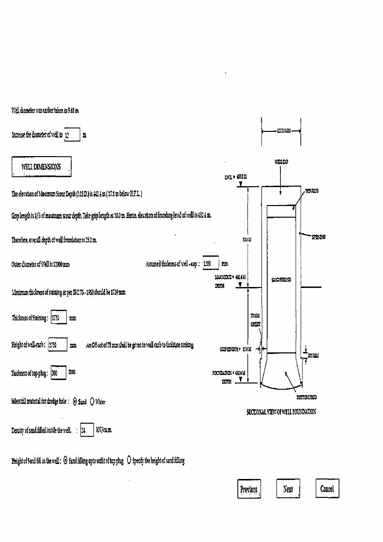
el dlam&; x as wler felon n9.61 m
1nulastthldtame:erofA'dto 1? m
I1
I:~asct — S
[ aLDI1I2iSIQN5 t c.t' (sly
1h decatlon of 1ltoamnm!our Dtpth 1SD,) is 1A m (11.1 m below EEL)
Gnpkngthls1/3ofmatim ourdept8iahlgriple1gthas1p,ontEtse,devatQ. offoundluglevdof,sellIs;31. a
1hlrlfo:t,mna0 depth ofyellfoundationis?31m
Outar diamltet of Well is 12000 mm ?ssnmadtithessofwta- ap: = mm
W.XSat4' 4MM Sit mitt rn i
JGnimumtiicai ssofstliningasp!:IRCYS 19$3choi1db!1729mm
lhidmcss ofSteining: 1_ ums
Fllhtofsslllcb; 1;U mm .nOff•setof11=shallbegiventoAceotofadlitatesinidng MMM,maa
liatknlsso toplog; mm YODWWCAM I tt'
Sdecl llmOltlalfotditdeIw1e; @$ad 011~amr cortmisuO
SK11O\AL1'1I1VOf LLfOt' Dd110S
Demitpofsen4il1edinsldethewe1l,
Eeighto(Sandfdlinduulll; O&ndfglingupbsotdtoftopplug 0Sptdh, thandghtofsandfuing
Precious . Next Cancel
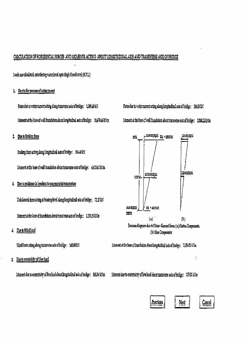
CA[CULATIONOPHOH1ZONTAlFORCES AND 1901(ENFSAC1U G ABOGT10\GI?1Z11ALA17SA DTR NSVEBSEAXISOFBRIDGE
loadst caladated tongdctlngxatta vd pOHI ltFlDedUcd(MU)
1, Due Ic the trtasmaofsrattrnusml
Foc detouek; amen ugng ongCattnasea>qsofbndge; 1369 k\
Montt atdt ueof alfowdagonabeotloag!tuthnalaa;ofbddgt; ?6,6f9,t6k\m
Dee(ogrokfnafora
g;EWngfnedttlogonglngltudlntladsofbndg : 16o'
if onunt at tk base o1 dl foundagon a bout tra,1ss eiIe aid of bridge : 6 623.6: k\' m
3. DuIaresidanse aheasiaaslommemepl iii Ie eralma
unbdatuadiomacgngatbmz gkvelalonlonitudlttrladsofbadge: P kX
Gomtatattlubaeofkundagonahutesiscesuadsof'orldgt:2.231 kYm
t Duelo:NYadload
11Lnd1oreamegalong traneasea4sofbddge: 169.W
Fao due touak;cotratugpgalooglangltudlelal Asofbddge; 6U )N
3loentattltrbokofdlf000dagonabottranssmuovsobnde; l$t22k~m
BFl i..`a~'OLRK Ft, I1l1SIal
U) (U !hosswa diagamt due to Icalta. Cutttnt Fora (1) Collie LompaSo,
(b) Sin campoeams
1lomenttthtbaseafkimn onalroudonttdlnaladsofbdge; 5,33131sXm
I Doetow altkftvofUcetoad
loment the aaaenlalo(IIi16adahoutlo iNdir<almdsafkidge; 9bS96k\'m alomentdue ttdlraflln bid about ttansttitsemisofbddge; 179$1 m
R Ne4 4 I ,cancel
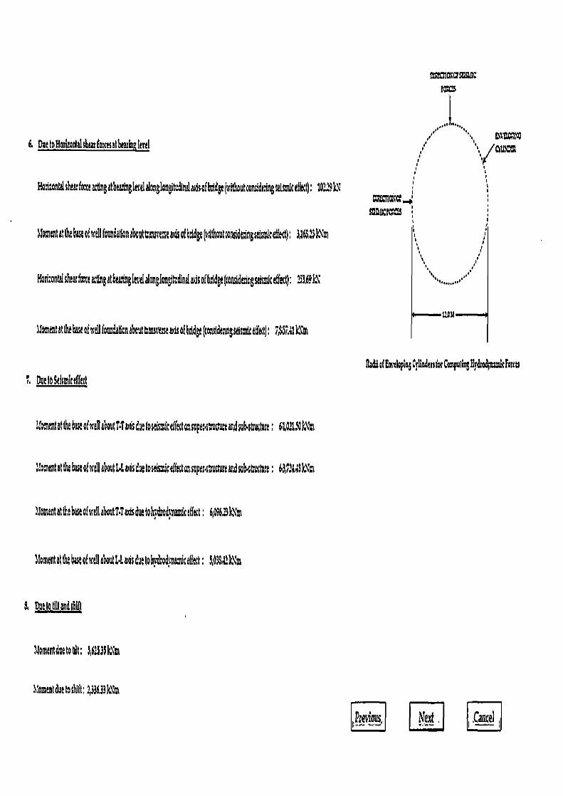
6. OngIoNmlaoEtatshwfos esalbwIaRkni
P.o:onW haa:fo:eactingatbradssgkvdalonglongltudlna Sofbtdge(ssithout ons!dringsalsdcef&iQ: 10219k\
t0
l9~nCPC~S
Sfoa~eutit the base ofstieUfoundatlon about t uveeacofoddge(hithautsasddtingtsmlceffect); 3d6Sak~m
tiasi:onWshearfataacttngatbea.tlaudalongloagftdinlalaLisofhddge(sonddtiagsatsmiceffect): 233,69k\
tomentatthbauoSlifoundatfon about eanss+t2blsofbsldga(cons!dasiegstlsmlceff&tj; 7JSSLUkn
Raddoftmxlopk CylInden for Co putinIII&COndcForcu
DudoSdsmlccf&st
toentatthe base ofscdlaboutl•Ta,fsduetosaisastcaEftaasupe:suctu.aadsubsulua; 6t,0?t,SOk\'m
..mmeotat the base ofswdla outGwsduetosrisniceffe<toasupe:at1cNta and sub.tCuslnre;
1lomentatthe base of well abontT•Taisduetohndsodsiundc ffect: 6p96:3kYm
Ilomtutatth, base ofksll about GL&Isdueloh}&odrnomic effect: 3,d3S k\m
S Nelagllandsbifl
.lomentdue ro alr 3,6213 Ie m
1(oment due to s}dit: 2,336J3 Wm
H L 4 . Cuuel ,
ANALYSIS OF WELL FOUNDATION
'ote>IilBouirgc.nditoniiomIatdharomdiaiiucloiakI2cnfntoomidcntiomxidln wind badiaanagIt d
IV g to;aldu~rnu'adlaadatmtgatthe6asaoftraIndadingthesdimlghtafwell
= e enlhoi:ontalfoxeac ngon the well atscou:lard
Hots:aAtalftceamngtsaourlatdlntt<edl:dlonoflOAgltudltlsladf p 694g61c HodmAti1omatt1ngatscow1eudinNedireztlonoftaustemSs 0 t~~60Sk\
'te:esulf~athoti:oat1forte,HIs6,914 kX
3kmmtthngattheb be fsrdl outIopglludittlads p I9U9D,93kNn 1lomentarbngatthe8ase c = 1Z3!23kYm
al a totdappliedaotttwlmontatgoutthebaseofwil,tuludiAgthouduetoltsmtdsM(is
Tnemultn!loot nt,lti105,396.17k m
Compuleli,l,y and];
wh e, Iy ^ manzntoflnntiaof base ahonttheadsnomtaltodlsetflonofho. nlalfortaspawnsduaughlbC.G•
IV momcntaflncmaofgteproJktada~atneln'atlonafsoilmssoffetlngtttlstante
I
Non, m K n11c Ragoaffiati:oAfaltoretgdceelfidentWu6 eteacqoAtb4u,httha6seraofraluesfo KV adKdehtauaedbrflddkstsmshallgtn:aVybeassumedasiaiiy
Previous Ned .Casuel
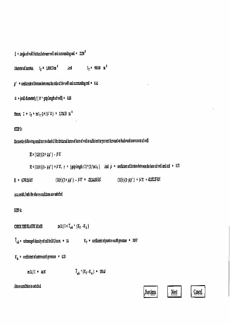
b °?r~aofrcallhic8onhdsti~enr,ella~dsutt000dlagsoil= ,,NO
1omer to! lnartlas lg o 7p6973m 4 And lt.0 OR m a
•C h1drnafhlrtlonhehreuth2stdeoftherrelland=0116ngsotl• Odt
a ° (n'elldiamlw)!(P' gtplengthohrd!) a 03S
Y6nz 1 • le +mIV (1+?p'a) 2 ;!3&33 m a
SIEp3;
Fnratthsfoll ningtatdlboatocheckiflhahfctc,talEo:eatbaseofs'dlissi!hdennttoptarentfor~•ard oftrtll
H>(IJ01PAµ')•µit
H<(M/r)(1.A#')+µ;t', r ° (gfinghl:)'plmlti.) Aid 0.11
E (1!!r)(1+µµ') .µ4 (11(t)(1 µµ') +µ;;' =40,15J7k1
?sas l6boththeabovecondonsmesatlsfed
STUD:
CBECNTBEEL,1SIKSTATE MNI/I 47' (K? •KA )
Yrp svtgaddRnsfts'ofso0ln)11 • t; Ks roaf9dentofpassireeanhpmssuu • 1097
xA ° rae;ddentafattlsaadthprauure a 4:3
m11~f • 4691
L„ - (Kp•K A ) •
,boreco~ldan is satlsfied
R Nest c s4
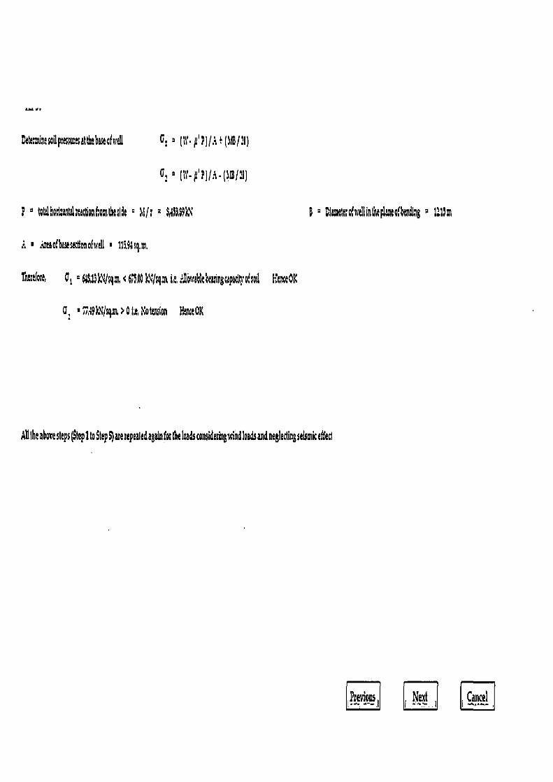
Date iaesailp misatthtbastaficell 0, ° 11Y•p p)/• '(M3/11 )
P° Otalkira~talrtacQa~hmOulit ° Mir 2 3,fl.MN
B ° Cleaitltrclntllinlhtplatuafbptdlag
i ■ no(baseactlonofwall ■ 1199asq.3i.
Tntztlae, C, ° 6$j3 \'J q.ar i it : gowa6lt eaing apadn o?,oi1 HtoceOK
Q: ■ ~d4k~J:gm 0 t Kottnsion Y,tnctOK
AD the above steps (Step l to Step S) ate rtpealed again for iM load$ considering nind loads and negledh g stmic effed
Previous l Nezf i Cancel
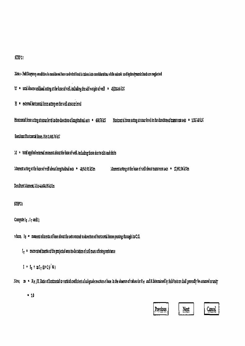
later•FuIlBouyanryrondllfonhtoroideredhereandwindloadiitakenlnloronslduati twhilesalsmlrandhldrodlwrdcloadsarenitlacled
It' ■ wwldostnwadloadi ngittnt6es6ofutll,indudingtthezelfutightaful! ■ 491;6611
H tdtmslhol:ontrl tort actlttgonthtstpatstouletd
Hod:ont4fotct6ctlngatsrourIevdla6tedtrtctlonf1ongNding ■ 6306IcX Hol:ontel for 6ttingdtscoutIevdtnthtdttKtlo not Canmseais ■ 1374DIN
tlesul taut Holotlal Pout, His 1,661,16 k\
M tote! 6pp1led&ntil momntaboueh66sstof well, tndudingthosedetooleSsNth
1lomtn;actingatfte atofudlalroutlondInd&ts ■ 14,915. IC''in Moment 6ttlngat the base ohe1Ia6aultrans<'esscads ■ b,69;,s6k.%5n
Rtsultantllomtm uic146W9$l m
Computtl6 ,Its anal;
i,ht;e, Is ■ momtntoftnttlaof base about tlsradsnmaltodimtlonothast.a eIfocttspassingI&oughltsCG,
Is matotof1wtiaof the FoJtttdauainelesafionofsoiltnassofetngsesistente
1 ° 11 t mI Il+3p'6t1
A'ou, m ■ &r,/g Paso oflc±ontal b eiU<altorfflcienlofshpdereacdonatbae.In the absenreofth.sk Xx an4Xd iminedbrhddttsts iA 1generaVrbeassumthuwuK
■ 1.6
Pcetitious . Nez! Cancel
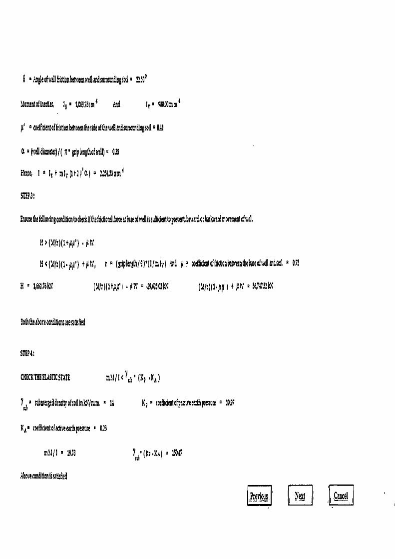
b °;:Igtl oftYd1f!(bbltwenWl1)B1dsutw1dings0il ° 211 900
Jomintofinitllls, I$ I 1,C6953im 4 And it.° 910.00mm {
µ'' telsidlofthftdLanda'tundinsod°O.a1
a ° (atll dit ltlr) f( n' g21plangthof s,dl) ° 03$
Hul, 1 p I+mi ti•(1t.p'a) ° 224i3am 1
thsm!thtfolohingcondt on tocht&Ift efdcgon4ltoneatbsseofwellIssufficient vementofwell
e?(1fr)(1+µp) .µs1'
H<( l(r)(t•pp) +µ1t' r ° (g1p1tngla/2)'(llmir) d a coltlidnIaftcConbl6cnthabescofdIandsoI1
H ° 1,66V6k I + ulti ° 164751kX
Bohllh!lboe!condlgatuec tlthS
S1'EP4,
CIECKTHHLASIICSTAIE mmil 7r.! • (K! .Ks)
Yrc+ ° submeglddr lKOfslllolc'gwa K a ° corIM ofpatlree pslssuh ° 1o91
Ka ° !olfficIntafactiteletlhpmsur! ° 0,29
ni J/1 ° 19,15 1th ([<a .Ka)
.oe tooth tlan Is Ms6ed
?9!.I' 9!. ' lezt Cancel
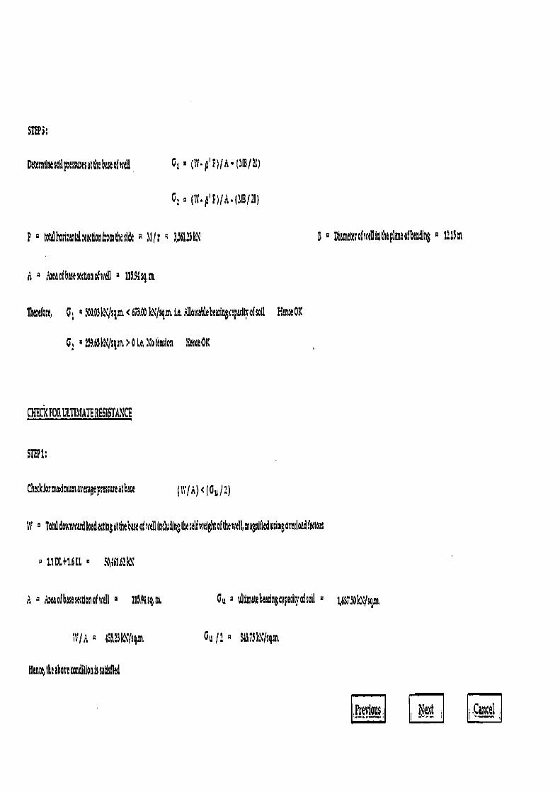
SliPS:
Deteatleemtlpetsu~esatthebaua(,rill Gs ° ( p?)(+a•(Bly)
P rota>ho>I:aalalrtactlanLotntheslde A Jl(r 4 3a61.3k\
e v7amtusctsrellizttlteplen:ofbting a 1W14m
d a ,Maofbascstttlonohcl1 2 11MS4.tn
G t ° StaOW11siz <E3.00 )N ftq. i. it r1toirab1ehaaingcapadh almil Erne OK
C. p:59,6lk\Jsgm,>0ie,Yoicnsin 8ne0K
Nkforn u=artragep,assureatbase (1V!•+)<(Go/2 )
.1' Tataldonrowatdloadattlngatthebasaof 'dIindungthasolfnelghtofthe c 1l,magiith dusingostdoadfatloss
tIDI+1611 ° 3061b21*\
,L~eaofbasestttlonoftrdl ° I1SWs4m Cu ° uIa atebeanngcpaci'ahotl
NJ,: G ~53,131a\ls4m. Gu J1 ° $43,73k;\Jsq,m,
Htntti Ihi than tanhllon tl satrsfkd
,Previous, i 1}_exr i i,Cancel
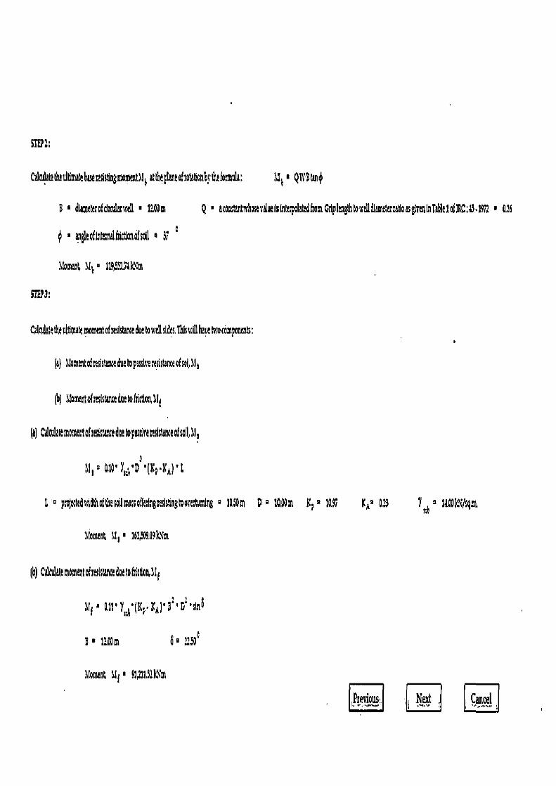
J11.1 S i
CdntlatethStlmkbanclstlngmommt116 M' Q143t$
dtctettrofdnulmsrd1 • 10Qm Q acontentschokralu°Islntepolatedto2tGdplengthtosrtIIdlsmetatatloasgtrentnTa61eIofIRC:9.1912 0.16
■ angleaflntn4htdanofsot1 • 37
XIoment M d 114,591S1k1m
•yam
C4cv1ate tltt itiomh moment of seistance due to srellstdes. This a ill have tiro camp°nmts: U
(a) Jo entoftesistaatedutlopassI teststanteoIs°I,lI,
(b) 1!on tofresistm¢eduetoM0%Ili
(aI C&ulat6snomtoftalstmc6duttopassirarsitat ofsail,al,
11,p
&i0'
L' poj trds~idVsoftb°sodmsssofkdri sIstngtooeatuming o 1Q$ D 2 10,00m It; m 1091
Moment %1, • 161504,O91Xm
K AY 023 Y~ U RWQ N/sq,nt
(b) CeltsdAtemomztofstdstii ii toflmonll E
Jf1' Q11 'Y~IKP K'A)'B'y'tlns
B■ 11km 6 2.o°
\foment, 11 j • 91111,3:X'1
(heviosts; Ne>d a Cancel
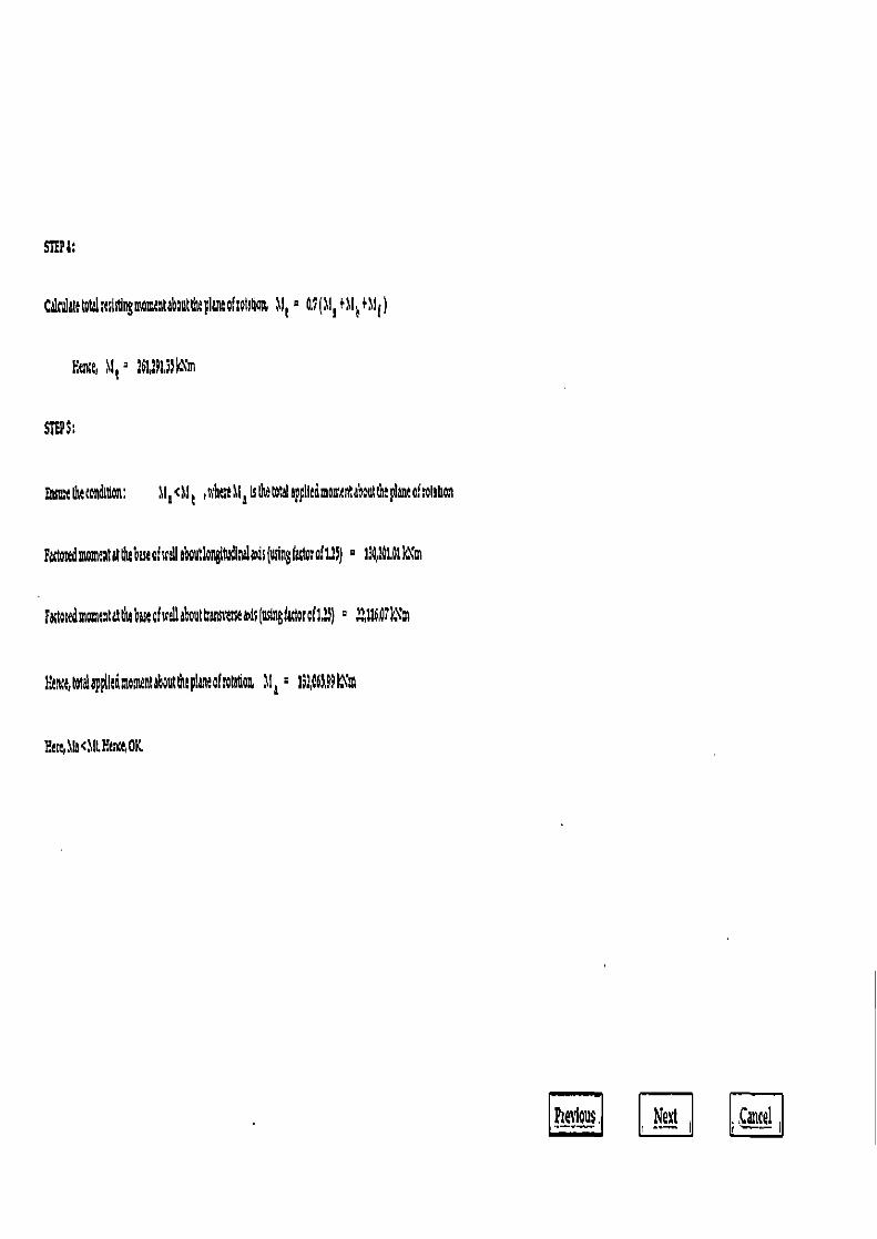
S704:
C ttuIMttottlstslstlngmomthtahouttlupl~staltateq~ 11t = 0.9(111 f\Vmd
Eente, 1!t 2 26U9153kNm
mm 6t condlflon: 11e CU t ,nhenll~slhetot plltdmoantabonttheplana;toluah
Rtotedmon ataldsSstat dlebouUongttudth4 h(winst torat1:) = 1%11.1kXm
Futatedmo~tatatttl4htuafsceI1 bout taosits &; (sinftdor of2) ° 22,116,Q7k"
htntlotaiapplltdmaasent but the pintofsotetlo 61 e 1963,99kYm
Ycevlous. Next Cancel
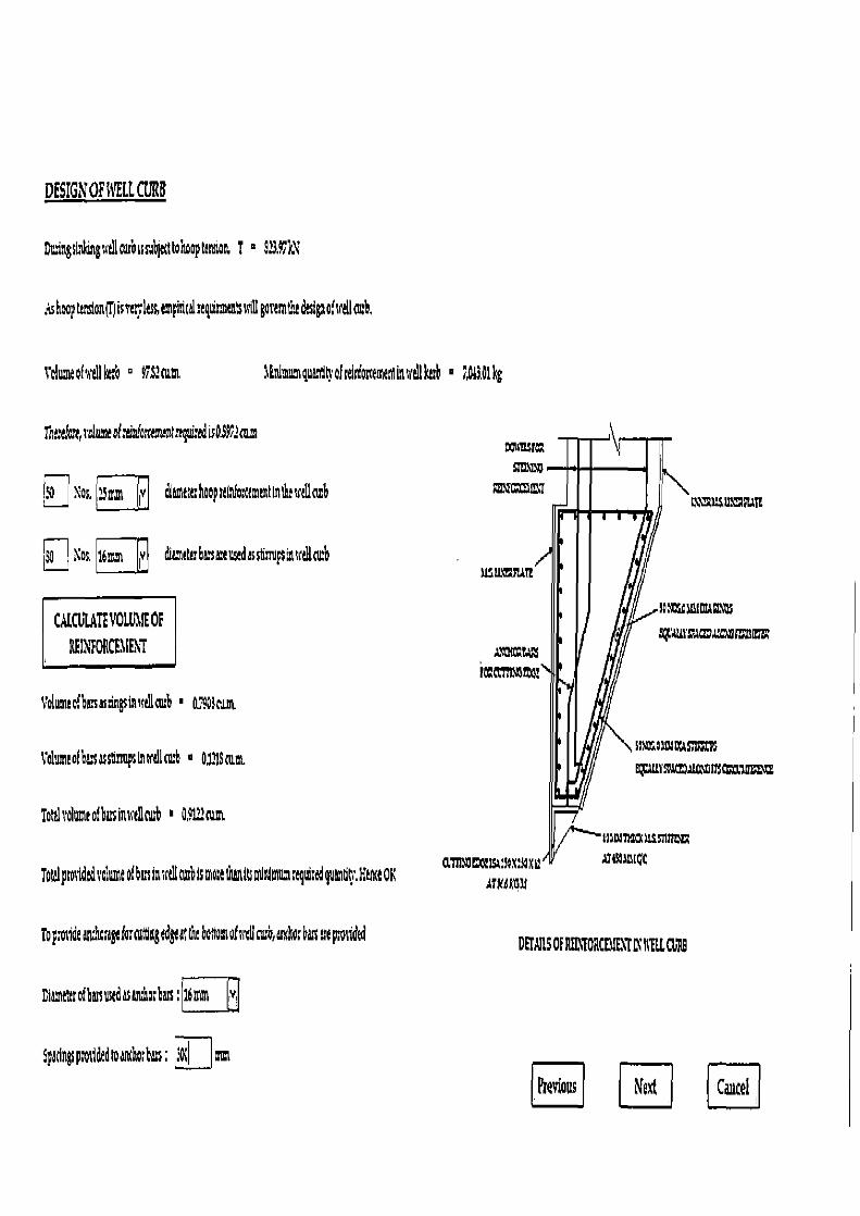
DESIGN ORTIL CURS
Dn~ngsinlongntllcurhissubjtcllo'noapctnrion T ° SJ,4ik\
Mbopcvision)isvc kssem ical:tq raitnbssillgommihtdtsigno!srtBco;h•
Volumeofatllkth ° 47,S: cum ILrdnnnqusntlhofeirdorctmeminsrdlktcb ■ 143,01 kg
mittlatt,Su!?tofrtinfaxers aq>n:edisO.$ cam xrmsr~
Nos. ;inm 1 Jiv &tmtltr hoop ctlnio;ctmtntinlhtAICu MV=7
I
NI HS,sL1 MTt
No 116mm v diamtltrha~sutusedrssrupscssctllcmb UZifl2sUTt
CALCL1ATEV01U11EOF
BFINFORM ENt qVusssr~®uc~as~ =
i~a~smaz
Volume ofhazas ingsinxelltu:h • a79 awn
Volume ofbu as sunup sInsrdlcmh + 0VIScu,t.
Tottl volume ofbusinxtllaub 109122c nt
ssvzosasousrs % E;.MT a~ =t csoas m7
Toialprotiidtdsalun ofbtsinsctllcurblsmo;tthMttmimumrtqulrtdgu~tln.IientOK ATROGIU
AT4HA5lQt
Topotidtt nth asageformltlogdgea the bottom ohrdlncb,asn]w;be gpodtd DETAILS OF RFL<'F0ACf1IFX1 L1 IML CURB
Dimexrofbmsustdasens±orhms;ii
Spdngspmtildtdroanthoch; 3a~ mm
Previous 57W Cancel
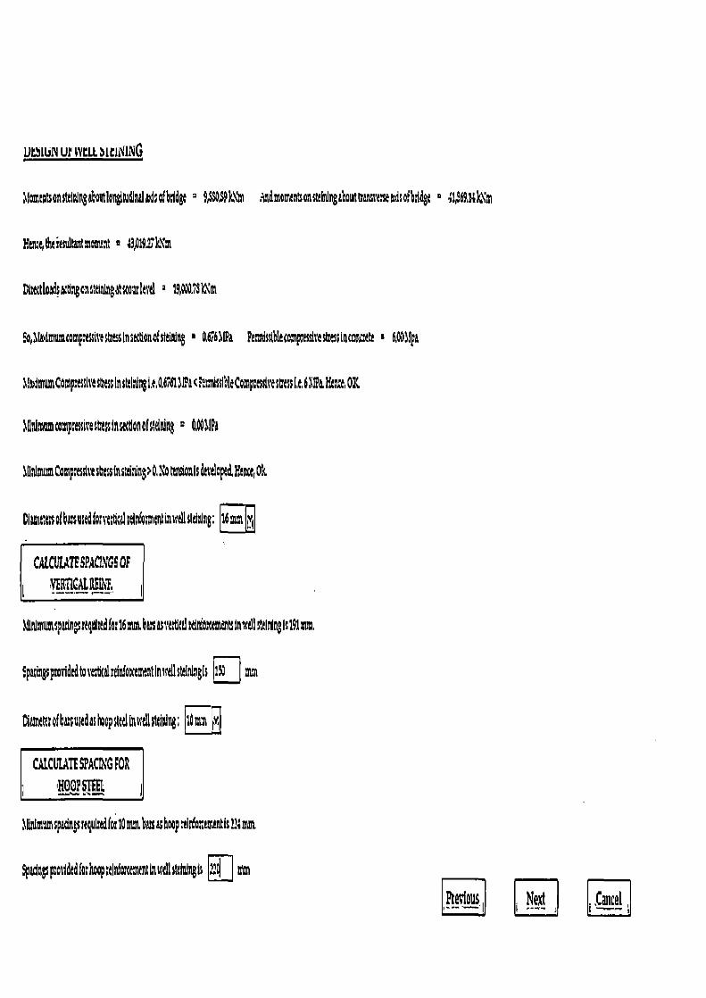
MIUN UP WCLL bICINING
~famantsonstdtUngaboutlongltudintlmdsafbdge = 9$OS9kVn dndmaountsonstalningabouttrannassetd ofbsldgt ° ~1,d6914k~m
Here duirultunmonunt a 13,019Z1c t
Dimtloads nganteoigtsmuslad g 19,0 1M
So,lrimmncompslssitYStresslnsectionofstlining • Q676~tPa FesmissibletompmslreslmssimmEutr I koollpa
J;~imwnCampsessiv~sCassInstelydngit&6ib1J!Pac?esa9sslhlecomp eulsest es ii.e.6 I!& Htn r, OK
~gVatomrontpsossi~esbassinsacgonofsldning 0 O, ITI
JpnlmumCompsesslttsCessinsttiflS>O,: O tusianisk pe&E nce,Ok
Ciamttasafbasusedfo;rtasalsdr`'omrtin dIstaishng; 16 mm
CAL CVIATF SPACINGS OF
~ ~ERtICAIRE41`E ~
Ili mumspdngsslqmtSfos16atnstiltsasrtltdrdnfoxtnttntsinwlpstalnlngR191mm.
panngspmriddtorebtalrehiIocmvainwellsfningis 1~1 mm
Diametetofbasodashopsitdbwdlstelning; 1n>m tv
CALCUtATESPACL~GFOR
~ WHOOP SCI i
~Rnimumspadngsrequindfos10mm bus &shoop rlio,'ammintisL14nmt
Spdngspolldtdfot hoop ;clnfoxemtnt6lscd1 tdth%gts ..d mm
Previous, R ! S~tcal
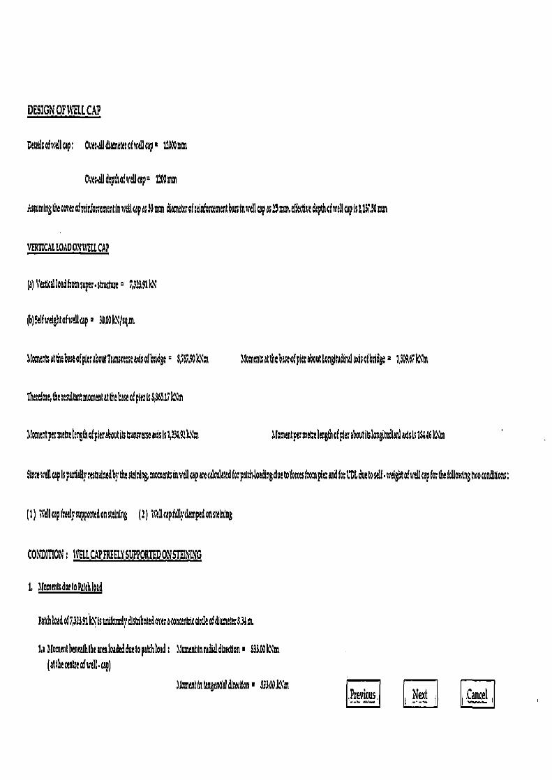
DESIGN OFIVELCCAP
Datallcofw Icap: OteeaIIdlamatetotu'ei1 cap i 12X mm
Owt-ildcpshoisrd!capn 12t mm
:.snmingthecovcofuIdostemnUnudtcapas70mmdiameurof:tiabscemntbiln'tll cap as1 mm, eff ve&pthafA Icapls1d91iOmm
VERTICAL WAD 0\ 11°E[L CAP
(a)Vertltalloadhomsuper•s Z32M1k\
(b)41Ardghtofic&cap 1&G k\(sgm
(omnaatthehsafpleaotTsanu'csaadsoftda= $ 67,9k"m 1roa~enratthebaseofplereboutton~ludlral~dsofbidge 2 1,6G96Z1o\1n
'tharcfom,thesesutottstmommtatthe base of pier IsS)3631 km
a!omtntpermekngtnofpieraboutth ansrtssanslst1391k\'m
ai entparmetIngthofpierabotl1ongltudlanladsIs164.46k.\m
imell cap Is resttaluedbrthecthingmomentsialtellcap are takula;edforpauhdoadingdue0forcesfomplaWfo.L'D6duetoS ii. welghtofud1apforthefollminghroconditlons:
(1) f4dl cap freel}'suppartedonsllning (1) it'llcap(ullydampe don stelning
COMMON: MILCAP FREELY SUPPORTEDONSTEIMNG
1, momenlsdneloPalth]old
Patthioadol7,33.91kXIsuaifoimt dlstrlbteotuaconcttc&deotdlamt; $312t
1a llommlbeuealhlhemaloaded doe lopatchlaad: Ilomentlnmdia dl ecuon • 33103k\'m (at l he (coke of sreU •cap)
ItntlntangeMaldL'tcan' 933.ODkXm Previous iJext .Cancel
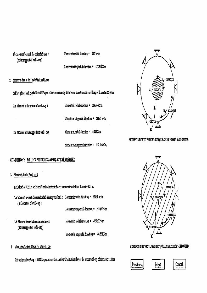
MOalE17S DUE TO SVS WEIGH[ Ilti CAP !REIN SGPPORI@DJ
1b d{mlbaaealhtetloadadaaea ; (at th seppmtohsth•cap)
a lomentin:adithadion= amk\m
alomintlntang dlditt Ott 16,7.4 4t
2 MomentIdvioSdfneightofuall•cap
felflreightaf; lcapis30. k'/qm.i chlsunWydistlbntedovertheenh.ewellcapofdiamtte;ilQm
:a Momanttlhu&ofneR•wp alomenUnradlaldisecfionQ 1&69
aloa tot intangentld lrttUon' 21t65kXm
:a bfomcnl allhasuppods of srU•op
alomentincadlelditedon : G.Wk\m
MOL1SOfh50AtQ AD0\1UCA 4REYSU'PPGAtE9J tomcntiatangantialdimtlonp 11QSOm
CONDITION: 11'E1L CAP EDLLYCLA PEDATTIIESU'PPORT
I, MomenisdnetoPalchload
PahhloadofZM%k'isdiomds•disdiYotedo to o ttiednleof diameter6.3.m
1a Momrntbenealhtht asealaadtddoclopalchload a fomentlnaadfaltUrn~ons 13155 M
(at t ha emn of wall • cap ) afomentlatargen61direcdon■ 25&1Sk\m
IF Moms banaalh the nnloadtduea;
alomentlatadialdIuction' SS.IOkNm
(at the supportofucll•ca?
hlamtthatangenllaldisonp •9a!?k~m
Z lmmenlsdetoSdfoelahtofsetll•rap
Self srtightofsraucap Is3GA0k /%..muhlchissulfamlydlshiduwdme; itenb;envellcapof hameterflQ m Pteyiotts Nett C.!cel.I
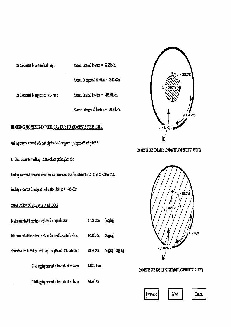
Stu
I'
h[OMt'TS DUE TO SELF IItIGHT pt'ELL CAP FULLY CLA,11PED)
23 6tomentat thecenht of xeI.cap
ltomenttnradlaldtetton° 79,66k\1n
1lomentin ingr<b I&ectlon ° 765k`m
:allomtni I the sappottsatsrtU•tap
Momeatnradlaldimtlon■ •135,Wk\m
1lomentintangantlldi:action° .2430k\m
BENDING MOMENTS IN WELL CAP DUE TO MOMENTS FROM PIER
trdicapnuyhetsstsmedto&epattieff•fiazdatlhrsuppoEsardtg eea!Gardi is30
11O BENTS DUE 10 PATCH LOAD ¢ttll CAP FULLY CUMfED)
Fesi tansntomentonsrdlcapis12 $42k"mpe:lengthof21e:
endhngmomentatthecenteofvd1 p due tomomenatans'etedfrom pierts.750390:+75039k\m
Bending moment at the edges of well cap Is. 1560$ o: + 19603 k\m
CALaUTION OF MOMENTS IN WELL CAP
total moments at the rm¢eofwdl4ap due topatchlaads: 5fl,39kXm (Sagging)
rotilmonentsall a tnireofwellcapduetoseut;eightofseStap: 147,UXm (Sagging)
Jomentsat the dcecentreof well .cap from pieraM npetsttartue: 75039 km (Saggin/Mog&ng)
Tolal sagging monied ii the teaIre of well cap: 1,a6913k\m
Tlalhaggingmommtat the caanrot well tap; 75039 N:
Previous Next Cancel
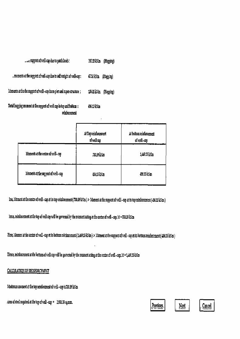
oppottohsd kapduotopatthloads: 161331Xm (H6$$h )
.mon r attbesappotcfmlkap due toiefweightofaikap: 6.S0kXm (Hogging)
bmen atthe thesupptthcdI•tphampitraudsupersnuttae; 156,Q$lNm (long)
Total hoggiagmomtnlatlhttoppo>lof welt cap into! audbollom; 56,13k:1m «ladattement
lttopttintortemtnt ofnellcap
Al bollomzddorctmmt ofxell•cap
Moments at the nnheofstell.ca i4f9i3k
Mometsattbesnppmloftcau.tap an cni 396.13bm
lere, Jomtntat the entr:of' eli•capatltstap:ah oxament(5039k\1n)> lfomentattbesappo:tofuvell•capatitstap:etnkte:tnt(;5613k1m)
lance,minfoxementatthe top Odtcaps,7gbe governed bythe nentat6ngatt ecenteofuell• cap, \l:7$ 39kXm
Ette,tilamentat the centeo} 'tell .tap atlts6tromminPottement(1X9.13!&1n) > tlo nentatttasppottofs,ill•apatitsbolromrtinfoxtmtnt(396,13k m)
!ene,Ltementat the b torofeliapilt ,e governed by the rnonnt &dngatthe certre of well .ç,llw1A69.13k\m
CA1MATlOX OF RE1\'FORCF1IEXT
lladmummountathetopSo,Kmndoicell.capI7SOJ9I ut
reaoEstedrtqulmdetthetapohceu•up. 2,4913$sq,mm Ptet+ious.. Next Catuel
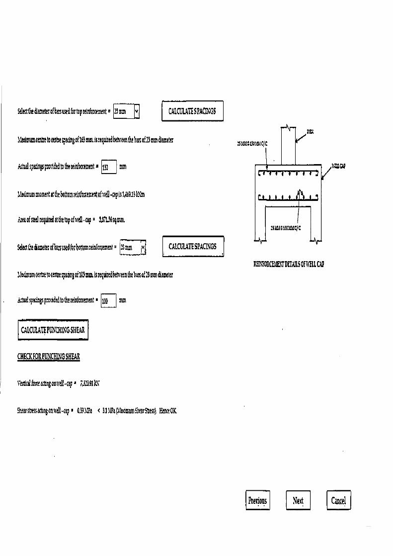
sisu:u
REIORCF11F.1'f DETAILS OFIt LCAP
Stltttln!dimttt:of6sustdfortoprtinforenant~ ?9oT Yi CALCULATE SPACINGS
11a durum t~tkt ~ ctnke sp sting of 16i aw. ss a gWrtd Ix9rten t~ bass o:1i mm di smtta:
toil spacings p otidd to tha tdnEo ttmtot ■ 1w mm
11a+iarom moment at tht bo ttom ]tintoxtmrnt of utll • tap is 1469.13 Mn
A;taofstelregidrtdotttt top ofsctll-cc n &S7126sga
Stlttttlethat; ofbersusedfosooton nfa:ttmev 3mm ~v. CALCULATE SPACINGS
dfmimomcenCetocettspadngoildicim, IsstquLedbetwetnthtbanoE2$mm6wltr
A twi! spBeings pm idtd to the Sforcement ■ 1pp mm
CALCULATE PGN CHING SHEAR
CHECK FOIL PCXCHING SHEAR
veticIforceacdngonccll -cp• ;3:E41kV
Shur strassactingond1-cep • O3911Pa < 3.11Wa(JtaamwnSh rS~ts ). Hen OK
Previous Next Cancel
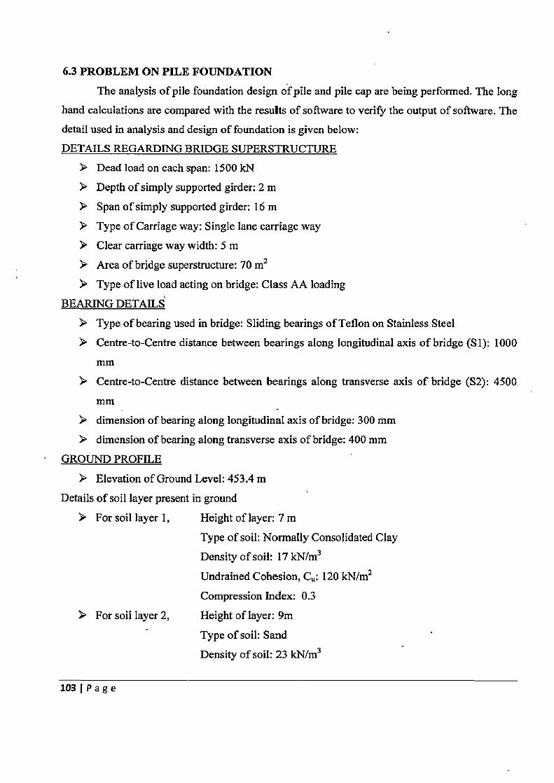
6.3 PROBLEM ON PILE FOUNDATION
The analysis of pile foundation design of pile and pile cap are being performed. The long hand calculations are compared with the results of software to verify the output of software. The
detail used in analysis and design of foundation is given below:
DETAILS REGARDING BRIDGE SUPERSTRUCTURE
> Dead load on each span: 1500 kN > Depth of simply supported girder: 2 m
> Span of simply supported girder: 16 m
Type of Carriage way: Single lane carriage way
Clear carriage way width: 5 m
> Area of bridge superstructure: 70 m2
Type of live load acting on bridge: Class AA loading
BEARING DETAILS
> Type of bearing used in bridge: Sliding bearings of Teflon on Stainless Steel
> Centre-to-Centre distance between bearings along longitudinal axis of bridge (Si): 1000 Fijiii1
> Centre-to-Centre distance between bearings along transverse axis of bridge (S2): 4500
mm > dimension of bearing along longitudinal axis of bridge: 300 mm
> dimension of bearing along transverse axis of bridge: 400 mm
GROUND PROFILE
> Elevation of Ground Level: 453.4 m
Details of soil layer present in ground
> For soil layer 1, Height of layer: 7 m
Type of soil: Normally Consolidated Clay
Density of soil: 17 kN/m3
Undrained Cohesion, C: 120 kN/m2
Compression Index: 0.3
> For soil layer 2, Height of layer: 9m
Type of soil: Sand
Density of soil: 23 kN/m3
103 Page
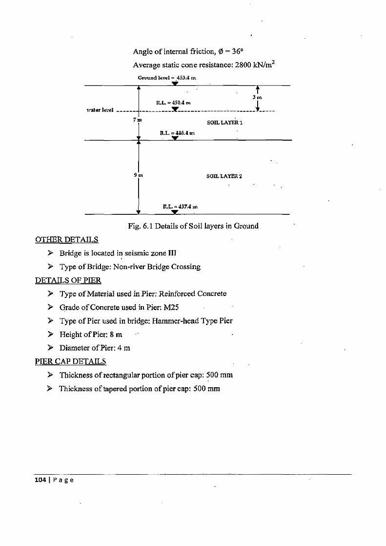
Angle of internal friction, 0 = 36°
Average static cone resistance: 2800 kN/m2 Ground 1ere1= 453Am
3 R.L= 450.4 In
crater level _-
' I SOIL L?YER1
R.L =
9n SOIL LAYFR 2
ILL. =437,4 an
Fig. 6.1 Details of Soil layers in Ground
OTHER DETAILS
Bridge is Iocated in seismic zone III
➢ Type of Bridge: Non-river Bridge Crossing
DETAILS OF PIER
> Type of Material used in Pier: Reinforced Concrete
> Grade of Concrete used in Pier: M25
> Type of Pier used in bridge: Hammer-head Type Pier
> Height of Pier: 8 m > Diameter of Pier: 4 m
PIER CAP DETAILS
> Thickness of rectangular portion of pier cap: 500 mm
> Thickness of tapered portion of pier cap: 500 mm
104 I P a g e
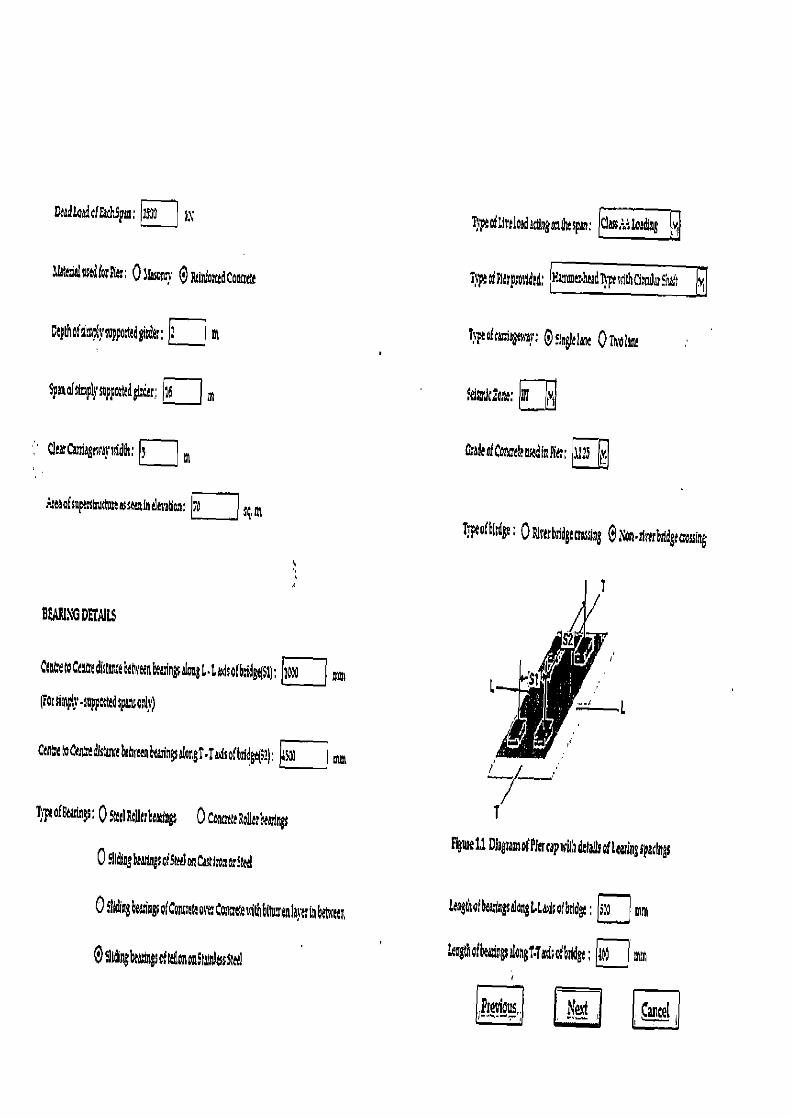
Deudtoadafrarhspan: ji7 yx
MAtedal nstdk r: 01f son s 0 R(infomdCoeae e
Ctpfhafsi~p(}supodgirde;; El m
SpMafsthspl}'mppatedgisde; lb M
Cler Caniegrsrdv n''dds;
r~eaofsnpr~structunasseaioeimbon: !? 1 sqnt
l)ytofUvelosdsg nthtspn: Gass::Losding v
T}peofFlerprotldd; K•_~~_adT}•Fessit___
TypeoFracigswer: Osleglelaoc QTs lsne
$tjc2tne: L1
CedetContetensedtnPitr; 11:s iv,
Tpeofbl4; 0tt'rrbrldgtaossing Olori•rlrtrbddgtaassing
BUN'o DETAILS
Cenit~CtnCedistsrreht6rtenC~a~n~a~ngL•LroFsatbidgdSl); 70!01 MM
(a; plp•mppOtted pot)
Ctnhe~Cenhedisgnse6rhre~btaringsalangT•Ta~iso;bridge(5+~: t~1 ~,
Lpeof8eddngs , 05:t1RollrrbtsHngs 0CorureteRoll bethngs
0 5Bdine beenngs o! Suet on ce l'os or!etd
OSIIöng6ea~agsa(Cancrctcote Coa;ewirhblh>menla}trinbebrttn
0 tidutgbet ngs oEttflonoaSlmrdassted
FtiueLi Dirgramot?IerrapsrilhdlaUsothtar>ngsparings
LmgthQt c&tgstgL.Laoibddg; jj mm
kngrhafheari~gsdangtiIFabridge; ahJ ma
Fieaiaus.. 11 [c ' j
I
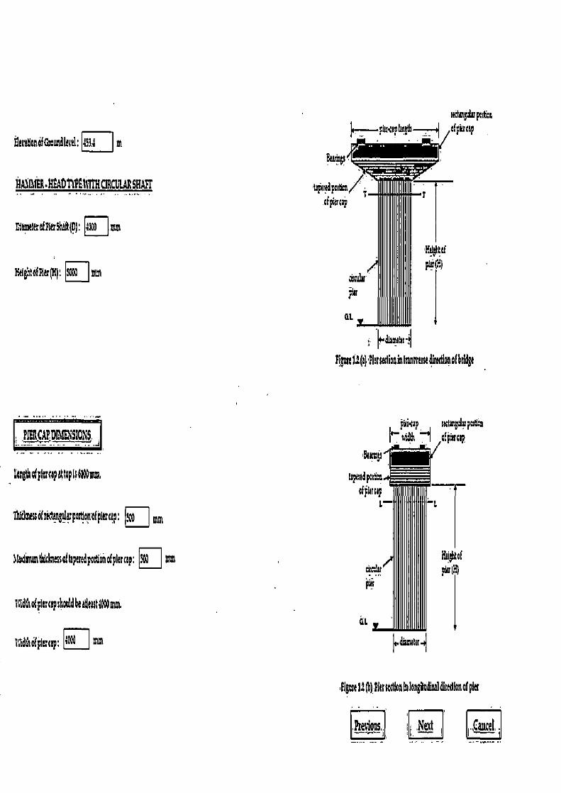
rKhngulup;rti:n
flaeatlonofQoandlatitl: 3.A m ~,—piucephepth--~ cipiuup
u N ER.E 4orn111THLIRCGLARSHAPE cfpkrc~p
v ah; Toth sh ft(D}: o mm
ticlgh:dEFirr(tti: Spat mm
~diuum~
lipre12(1) Ph; srclioainIransscnadhsbnofbddga
i _PI fAFD41(E~ISIONS ..J
>kngth ofplrrmpattop Is61Waim,
p&sp nctuç FMA ; fp~rc~p
7NSofrictangulrpardonofplrrcap: I,
a(mimum~Clvussa}feperedporSonoEplaccap: Itrm
dlhofpirrapshoaldk&thUt4G mnw
1l1dlhofplac5p: d~ =
Pigwe 1.2 0) Picr ctd n la longdadinal dhsion of per
Fcevlous,i i ~ ,Nett i . C, ancel

Stresses due to dead load and self adg6►
DeadloadhomSupetstuttu:a a 3070➢~
eltsraightoteierand Pier 3p• 3,07MLN
Totaldisectloada,•tngatthebaseofpier • 6,7,SLX
Sawsattlngattltabeof pie detodeadloaandsrlfetght•;S3,1OkX/i m
Stresses due to ecceutricilr ofIre load
(a) Due toweactrie lire loadabaatTransrassea hT•T
Faroal live )oada:tingat the baseof pie: Is3S3.00k\
Lomntdu6tott(neidnoflira load abouti•Taus• 192,5 LX•m
Sha;s atbauductoeaeatttc live load aottranssarumds• 61:7orGC 1ccJsq,m.
0) Doe to eaantdc Ere load about longilndioal axis U
btaumumectenbkUveloadattingon the pie: caaflnmomntabout4tasl 397i k\idatt4ato.9lmkom the 1,,Ladsofbtidge,
lfomp¢duttoeccenttl Itrotlira load abontlanotudinalads• 37,63k\•m
Stcessatbase due toeaentrirllre load aboutlongitudinalasds• 91,;aor•:S47kXJsq,m
Stretser due toIoneift ua!forces
(a) Doe totmdne effort orbsakingfoses:
g:alngeffectisinv ia1ypeatarthe!tnatattiraeffort
lonitu&nal force due tobldngeffo:t• SO.Cdk\
Conddeingthatthelongitudltilforau711bactingattiu coIdof the tehideuldchIsassumedas>1mNghhom the roadSace
.lomtntatbaseoipierduetobrakngforce • 1,000AOk\•tl
Straessattu base of pier due tobralangfote■ +159i5k'Jsgmo:•159,15
Previous Nazi Ejj]
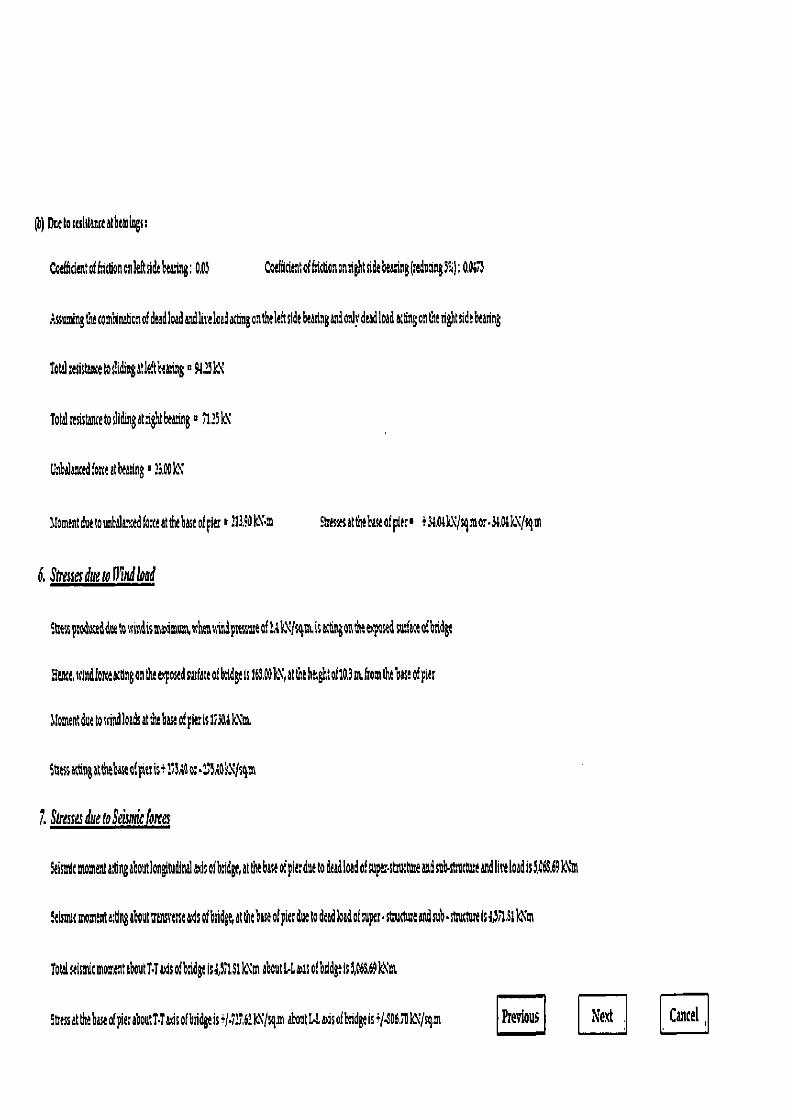
(h) DEC tolehtanteatbtalogs:
CaefidentoHlctloncnleftsidebeadng: OA3 CotHidmta1fticGanonnghtsidebea.ing(sadudng9°A); 0.001
:.ss~ingCiecomhiwbonofdeadloadaidlirelcadattngaatfitleksidtbearlaganda Jrdeadlead Ktingonditrightudtbtaring
Tot~usistaneetoslidingatle,Rbe~ing ^ RUN
Totdrtastancetodidingataghtbeanng = ;1.39k~
G tbalanc d font atheMtng 1 a.DW
Moment due touebalanotdfo;ceattlubastofFitr' 113.9OW-M EThstsattheb&ofplr' +3&oskNf4mor•3& kXlsgm
6. Stresses due to Pend load
:Ctupsededduetotisindismaamom,whtawi dpsesrateof: )sgmisactingontitttqcsed s'id3 eofbtidgt
Htr«e,u1ndforceatongontlueapostdsurfateoth1dgtts169.d0k",att thtiotof10.3nt, from dubastofpier
Moment due to wind l oads at tlt b ase of pier is 1730A k\ m.
5ttz acting atdiebase aS pies is+ 15Aa OT •174k*'gm
7. Stresses due to Seismic forces
Seismic momenta:dngaboutlongitudinalaxisofb~dge,atthebaseofpiatdietodi dloadofsuperstmttureandsub•stmctureandliveloadis3,06S.69Mt
irmkmomtnta;tlng about tmnsrerseaxis of bridge, attntbaseof pier due to dead kid of supts• statuue andsub•rttuttmIsa,711.51kNm
Totaluismicmomentahoutt•Taasofbadei&5151kNmabout4LasofbtldgtIs3e6A69lot
9atssatththaseofpierahoutT•Taisofbddgeis+/.9L'.6?k\7sgmaboutUaxisofbadgeis+/$O67OlN/cq,m Previous E Cancel
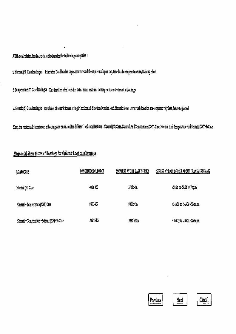
ABthe cakulatedloads ate dasd ledunderthcfollowtgcattgolies;
tXosmal(N Castloa&g; 1t9tdudsDa1cadofsupttstnxuaandtltoEp(tzsssthp1Gta,Uve1oadonma4ts1cnue,Bs1ngtifo;t
2Temptsamst(T)Cattloadings; thlsloadindtdtsloadduetofdctlonaltshainttottmptututemovementatbeadags
$ttsmk(S)CstlediagsI ItlindtsofstlsniiekrctsacBngmhosl.onfdldlrcttlanOrssutdload5iesmltfo cts intttllul ditectienuerompasatlstil; lessher¢engltcttd
w,ththotizontalshtasfote atbeanngsatcilndandk;dll(tettloadronthlnddars•lomdtj CazXoui:adTtmpaalue('+T)Cese,\o:malrnd? pt;alueAndseismic(\+TI)Cau
Heri:osttnl Shear forces atBeariu for O ferattLeadcontbbtations
mm tO'GTNAL1OEE 1f0MEXTATTH!easEOrPIER STHESSAT9ds!OPPIFRA6omilgiYEB$FA~19
locmal(Case 4.00 \ 37:k\1n t 9i1ord41k(sgm
\atmeltTtmpt;amt(\+T)Cast 96,73k` 9DJk1m +u31 os413 klJsm,
XotmaltTempetattntt4lsmlc(XtTt9)Cast : 3Sk1 2193)n% +363,M'o;,565:1kN/sgm
Pre!rious. Next i Caul
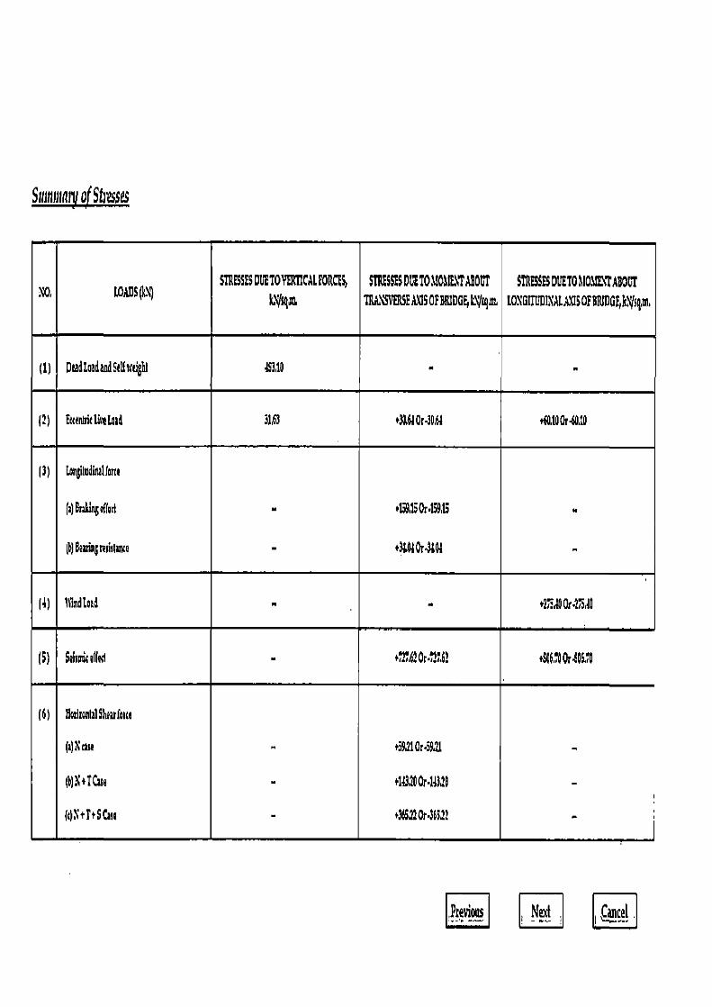
S:unniani of Stivss¢s
STRESSES DDETOVERTICALFORCES, STRESSESDDET01I01I!XTABOUT STRESSES DUET0110a!t1TABOCT W' LOADS\) S,VR TII,L\SVERSf1)3SGFBRIDGE,LIga LOIGThtlXt[USGF8BIDG6ttgm
(1) Dead Laid andSdf%dghl 45310 - - (2) Ettt tdtth' Lord 3163 +30,610r-30,61 +0.10Gr 60,10
(3) Lonbimdim1forte
(4Brok1n6e((ad ii .159.1SOr15915
(4) 8SçruWtane - +3LW 014141 -
(4) 111nd[otd - - 12754 OrtiioAI
(5) Seiroute(fed - • 2762 0r.72.6! +566,'OOr106,1
(6) NotlronlilShealforte
(1) N the +3911015921 - @)\+TCae - +1132001•14)20 - (t)B+i+SCai+ - +365fl0r 3fi:? -
pcevi0us Nezf C, ancel .
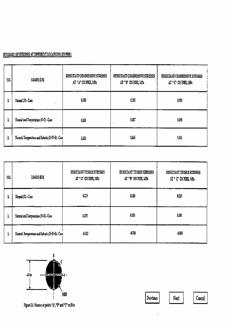
SL.1LMARYOF STRESSES AT DIFFERENT LOCATIONS 01 PIER:
X0, LOADSP1) RESULTANT COMPRESS!YE STRESSES
AT'A' 01P1ER,11Pa
RESU TAXI CO I2RESSIVESTRESSES
AT IT ONPItl W&
RESULTA\TCOMIPRESSII'ESTRESSES
AT 'C 0\PAER wl
1. Iota (N) Cue 0S90 0'63 9,769
Z 1omu1 mdTempensure X+t) •Case O,g30 OSST 1490
'omaLTimpnahvamdSehsmic(Y+T+S)•Case 1,51 1.543 1.553
\0. LOADS RESIITAVTTENSIIESTRESSES
AT' 1' O1 PIER,1Na
RESLITA7 TENSILE STRESSES
AT'B' 0\ PIER aea RESLILL\TTE\SILESTRESSES
1T' C 0\ PIE11 dfta
1. Nommal(N)'Cue 0.119 U0 0.259
1. Noam4 and Tompmlwe(Net).Caw 0179 0.153 0,143
3. Nonul.Temp.ntue and Seismic (N+i+S)•Case 4351 4755 OSLO IUt
Figsnell Streaeselpoinls'A','B' and 'C'onPies EE Next E

CHECK FOR STRESS:
(1)11&ummn comprss h t cUtss undts N Cut loading • 03511 JPa t 60001 Ba Ht mt OK
(t)Mat1 omcompcnsIwslimnndtsN07Castloading•11S90.1a<6.909M1'aHtaccOK
(3) 6 sasimmn tampstssiee ctrtss odic N #745 Cast loading a 1Sf)11pa < 900 J Pa Hiatt 0K.
(11JfasimmnItugetlstssadtaHtTt 5 Cut loading■OS10191<L3501!hNinaOK.
Hence, the assumed section of pier Is safe.
Previous Nett Cancel
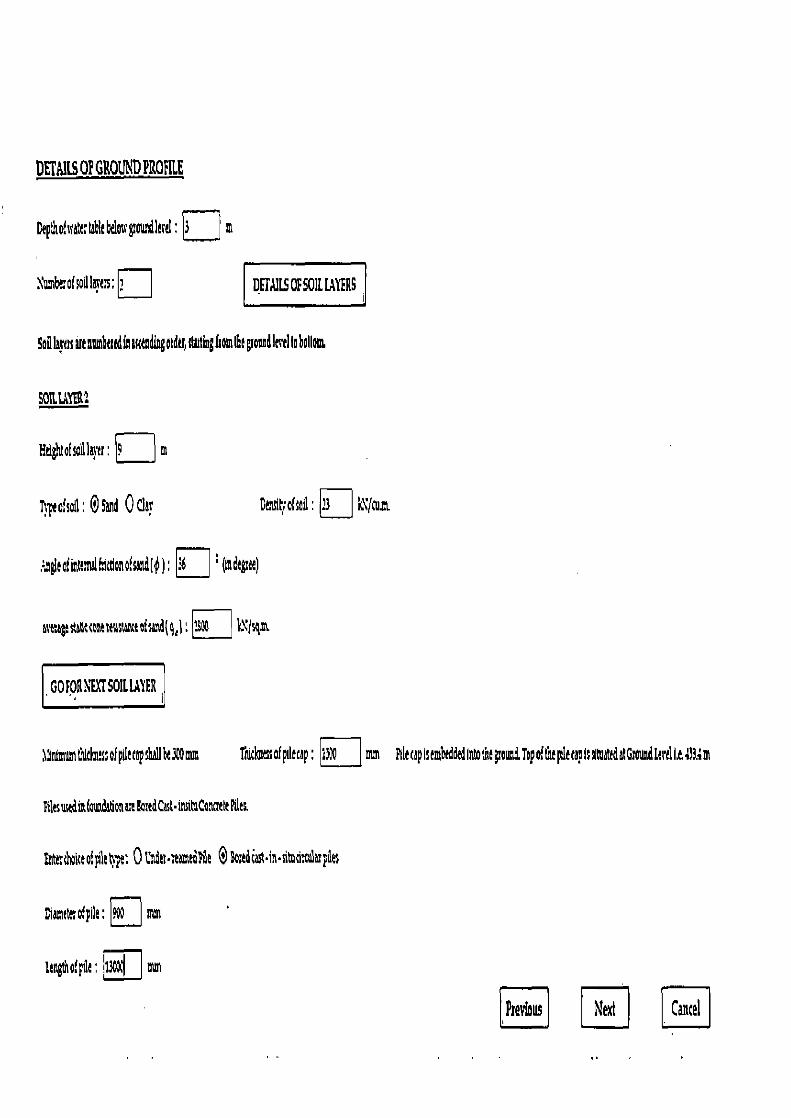
DETAILS 0? GROUND PRORLE
Depth of scoter We belotc gourd level : m
Alsmbeof odlavcs; DFGULSOFS01LLAYERS
Soil hva ut nn *tttdfntumdiagotder,dMingfrom6tgonadler'tltobollam,
SOILLt3 2
Hdglita(sadla}tt . m
ltpeofsoll : 0 Stud 0 thy (ttnsih ofsail : ?3 k\'/cum
;~t~tofinct;ncIFicdanofcndf¢); 36 ° (indtgut)
at~agtstaaccostmiststetofu~dl9~l: BX k\fsgL
GO FOR \E%[SOIL L,IYER
1lfmntin Ndm!ssofpdttapsfthllkA= Tolclmssofpdtcap: __ mm
4ikcuedit(oundthonazek edCut•insilaConsttttttitc
Fntt:shoico'.pilhpe: 0UYdtr• eomtd4ilt 0ktd ast•1n•situdttalupiles
Lyamtssrofpile: a mm
ltngth of pfle : 13t cI mm
FdectpIstmbcdded Into lntgrouniTopoheeleltraplsslti ttdiftaulltrtlit4 3.4m
Ptev(aus Next Cancel
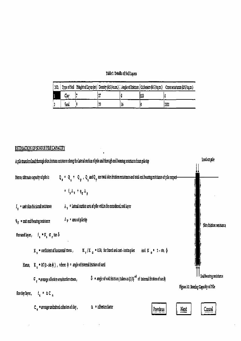
Ap0ttramiersloadthroughslslnhltaon%sls;anca slangthelattralsudauof pdeandthoughand S 1ngraststanceLompdetp
H~ta,nlumtccapatlt}•ofplilIs Qa, Qs' Qe,Qs°ndQPsetotalcknhlttlonsx;istasscaand
9; +smitmd6earl"Stance Ap ° araaofpiletlp
f s - witcknhitBanolrctlstduo d s ~IattralsmidtasraoipnasciUJnfn:romidedseIIJa}c
Fonaed byer, f I • X5 Q e tan b
FRnce, K s • O;.n$) , where Q c angleofinternaIM onofsand
K s °ceeffdeatofhoslsontilstttss, K, /E a •OSD, forlmedandcast.Inssnspies
S ■artagediKUveararbwdensess,
Af s ,+gr A r
8 • aneRofsealtfmcn(takenas(?f3)`' of intemalftictlonotsand)
Figwc 31 &atia cipadly of Pile
on pile
astari e
Tables Ddeof Soil 11ps
NO. ~ Z.Te of !all H:IghtaiWrtr(at) Dt'tlh(k\fma,) Angle ofldmonICobalon(k\1sqzt) Colt #SSSSancclk\Jsgm,)
Glas ft 11 0 1:0 O S, 0 33 35
ESTIMATION OF SINGLE PILE CAPACITY
Forda}•ks'r, f s a tt C a
C p pareragendralncdmheslonofday, a p adhesianfubr ptevlous i \'ezf Cancel
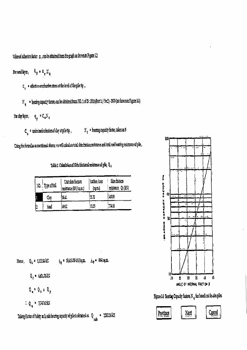
ABa(1 CI INIelUlat FAVION d
igrnse3.3 8tatgCpacit} tatlasX q fosbadcasUn.sitepilts
Ptevlous ; Next I ,Cancel i
valuaofadhacionfattol u,cahbtoblalntd(ronlrhe~aµ~asshots tleFigtc~l:
forsmdla}rt, q o I aT %4
C, • eSctS nct:scattkkt 1olf pi1dp,
9 6tingrapatdracto„cIA obtalatdhomEG1oEIS;11(Pot1)fec:)•19~9~asshotrainfigalea9)
fords}'la}tir, qr °C°N c
Ce =und aedcohsianofdaratpllatlp, X c :beanngrapldnlacro;,Gslcenas9
L'm 3t tio~avalasas~endesud abotbsaealllsakulaletelalslastFutk%Ilstw eaMtatsleadbea;ingt tht&geofpGe,
Table:CilmlatroaafSkintsidiabalstsatsateafpile, Q )
10. o Soil GNtthnt ctcn sa:face s ea i 5hataian
swish,' kl/ q.n) Qs ~C~)
Clay 16,y1 it21 Ii19A1
I2 SS 49S 15Sf `iriS1
Eance, Q'2 laa?sleX
qr ° 19,11132N(sgaa Ar ° 46isq,m
Q r a 6,B:u'Sk\
Q,° Q a ~ Q F
Q° Z74I6:k\
iakingFatrorofsaEttcas3sae grapadrrofpf)tIotneds Q a ?5S1,Stk1
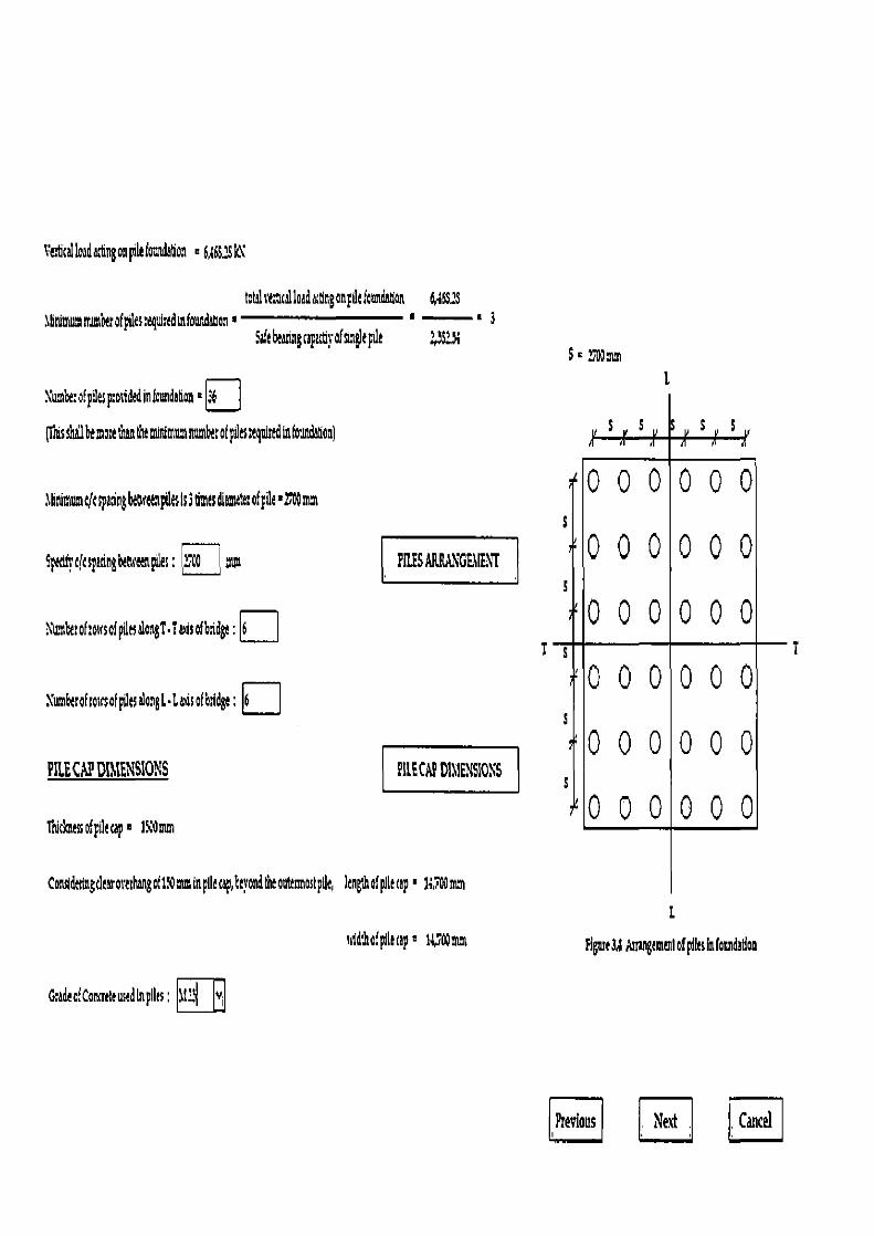
Te:ficalleadacgngon phi foundatic - 6A6S:SW
total;tcloadactNganpilefoundaon 64SS1S 1gNmunu Sot piles egWredsnfoundanon a
5afebeasingcapac6rofssnglepile S-:;A1mm
Xumbe:of piles p:osidedinfcundaflon
ICNs shall be molt loan tfx miNmugs munbet of pits:egnind m fous~on)
PILE CAP DIMENSIONS PILE CAP Dt1ENSI0\S
Tbic ssofpilecap- 150mm
000000
000000
000000
000000
000000
000000
lgNmamtItspa1ngbtaceappesis3Imesdiamcta:ofpde•27 mm SI
Spetlf;c(cspanngbercaesp1&: rcamps PLIES ARRAKGEIIT
dun xcof:ossaf pges alanT•Tatis ofbridge : 6 T
Sumhe:ahosrsafpUesalangL•Lsdsofb7dge; 6i
-T
Cosldeilssgdearoralsgof17Omminpile cap, leyondt toutesmostpdc, length of pile cap - 1v-Wmm
L
uidthofpilecap a 1a,T00a~ns FigmeU MrusgemiNofpiksiafonadation
GcadeofConatte used in puts :.\I2
Previous Next I Cancel
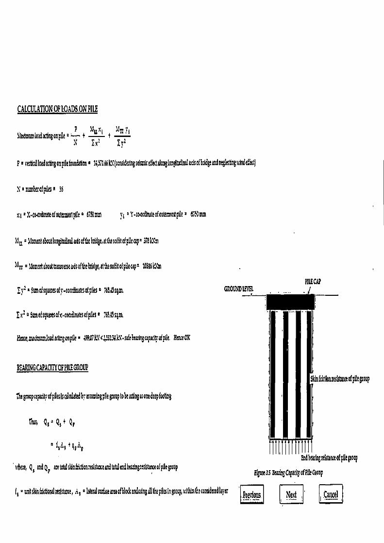
CALCULATION OF LOADS.ON PILE
P 11u x t Ur •s Smun Ioadactlngonpile 2.....-. + — + - N Ex 2 Fr'
P°re~cilloadastlngonpiltfoundatlaa• ia1766kX(considetlng5d5>n1caY onglondtudlnalarisofbridgtandntglcdngindtffat)
N I ntherafpilts 1 36
xs ° X.coasdinateafoumnnostptlt ° 6f50at 1 y t ° Y.coo natto!autesmostpge ° 695um
11a =alonantaboutlongitu nd&toftebndgtattuso(ntofpilecap:S19k~a~
11n ° 1Wmsntabautt ann'Etwaisofthebtldgt,at the salhtofpilecap= 103161s\'m
Pat"? fro ° Sumafsqua'esotr•coo dinettsoEpilts ° f67d3gm
Ixtp9unofsguastsofx•toardinausofptlesa 763.43sgat
Nerce,awlmuatladcbngonpile' k\'c 3131k .safebeatingcp4ofplle. HenceOR
GROUND
BEARING CAPACITY OF WE GROUP
the groupcapaciM1'ofpilesiscalndatedby assundngpile group tobeactingasonedtepfoohng
Thu, Qa ° Q,+ Qp
° I1l'1 f qv .ip
ofplltgtoup
Fnattangstutanct otput group where, Q, and Q? are tow skin@ictionrnistause and total end beadng:eststanceof pile pop
Flgntt3,S BtadngCapttftrofPtftG[ap
f s =anftc1n6ictlanzUeflstanct, A, ° lateralsudaceareaofblockendosinga1Ithepilesingtoup,sdlhlmthtcosoidendlayer Nezf ' Cancel
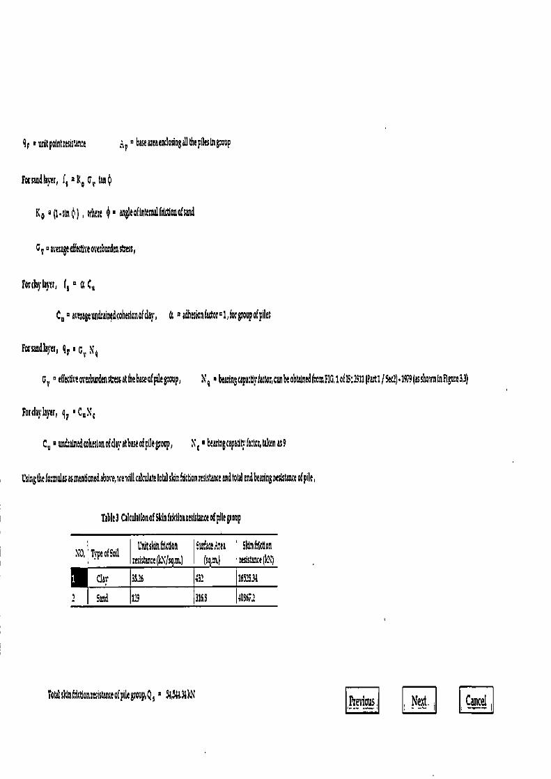
9p +nnttp0lntftsis'ante r ° baeareaendosioga11theplestngroop
Forsandlayer, 1 2 Ko Cr to¢
K o a (1.n ) , nfhar $ ■ anglaofintem hlctlona'sand
Cs rergaeffetlteoa+tr6nzdenst ss,
Forclayl m f a a a Ctl
C n °acaageundraiudcohaslanalda}, a 2adhasia"(odor-1,forgsou2ofpile;
Forsandlayn, 9p 16v N4
G r ° a(tattitaorarburdensLassatthebaseafpllegoup, N4 +6aaringcapactlplattar,tan6tobWnedfrom110.1af]S:1911(Part1/Se2)•19i9(asshosrnfnRlgme33)
Forday'layer, 9r ' C,Nc
C n +undalntdcohaslonofdayatbaseofpIkgroop, Y 'baanncapad:fattor,takana9
Csingthe fo.~nsnlas asmantianedabove,sfexdl calculate total sbnfdttionresistatua and fatal and beating resistance of pile,
Table3 CalcolallonofSWfdctlonaesblaceofpllagsoap
So, TspaofSoil L tsldnfsictlon Smfacr?waa Shnflcdon resistame(k\Js m) (s and sesis,ance k\I
C11' 3S16 432 1652531
sand 113 316.3 406611
TolditfsittlonmistaneofpilegroupQs 2 N,%i31lG i Cancel
q r ■ 10A13,3 lX/si1 it • 201.36sgm
Eancr End6radngttsl ancrofllr, Qp ; Z159,9i3$6IX
Thtuitmaabta ngcipanyofpdrgroupi S1intmof, Qa valueulndattdasabOVVe Anil
II Q1
n A nuth rofpiles 0 36 and Q o nitlauhhradngcaparin ofpilr
ftetom, nQO R Y1,41;BLN
E%r,vltlma;trasingcapdhrof pile go pis 27,91635
TaWnfl&b:ofSafetras3,sre nil! gSebeai1ngcpadh•ofplkas Q = 9;97t161CV
iafalloadacGngonlouadadon • 1lL muatloadaaingonpile X \umberofPilcs
494X36
C Si?66
Mena Safeheadngcapadn of plle group • 9Z97,46 k\ > Toral loadaaSngontawtd Uo t H ce,$ah
Ihetiaus, Neat i I.Cancel..
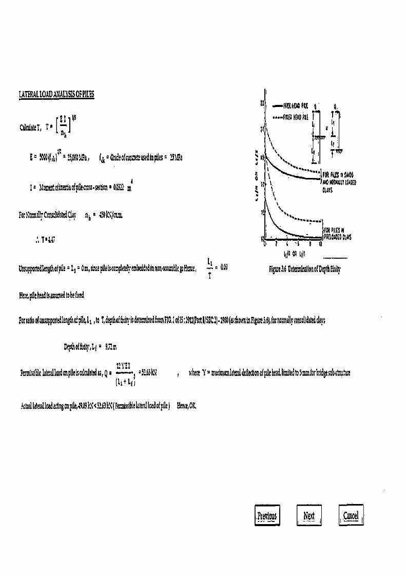
LATERAL lOAD AN'ALY'SIS OF PILES 41 —fPff NfaO P4E 1 0.
EI 43 i •n-PfEOREADhE f T- cGndeltT, T' Q ti II 911
E° "~(Il~ 23,l3Da, Iy Gradeofc reteustdinptles= 11Da ►> ~~~• tLi lJ
, Q •..••••,IPPPPall IM)s I 0 ~1. - Jlvo Iluu so~oEo
® a(omtn toil ntz5aofpdaress.stctla' O322 m ; f ' a. dart • Y
Fo;o mallrCanschdaSClar nN &'EN'm. '•.l
T'1 PSI - . ..WfPPlloaOEE 0 i i "a 0 11
lt~p OB till T
UluuppottdlengthoIpile~L1 s,sth pllaiscompkta1ymbedddinnonuau1egHene ,s p a~ E7gme3.60ettiminalioaofDepthSiig' T
Fee, pit htad Is assned Io b t S
ortadooionsopponakngtnoiplla,k,roZdpinoi kdele lnrdho 110„oii3:911(patI/$!C:)•1950(assholminFiguta~6hfosnomallpcoSdltdtlps
Dtprhofb1 ,lf
PtnrJssible I r4loadonpdtiscalndaledas,Q o og?b3k\ n'hett Y madm ilahraldtdatlonolp~thtad limifedro§mmlorbtidgtsnh~~utwt (Lt+111
ctuallatetal load actlngonpilq.9.49k\<5.+.63k1'(PascdssIUtlattral load of pile ) Hence, OK
.Ptevlou6 Next .Cancel
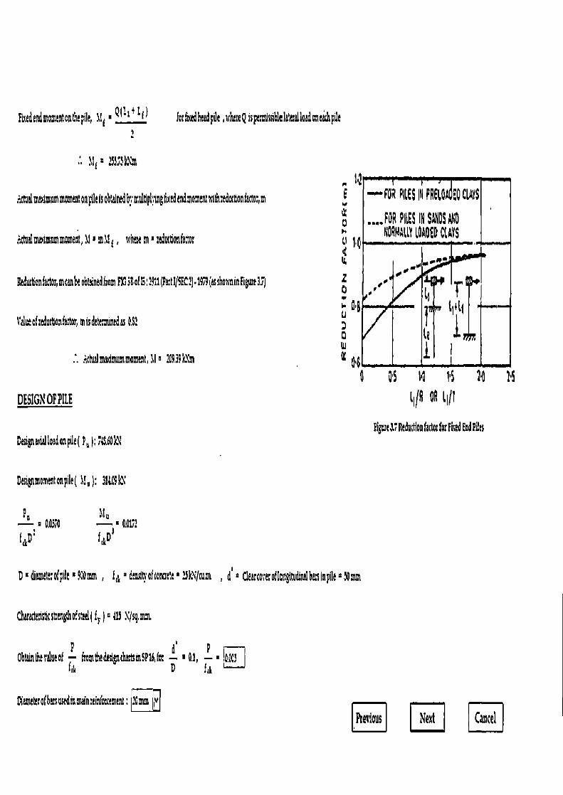
Fudtdmomtntontiltpile, Us • Q(1+ t) forfn:adheadpi1 ,srlureQipmltsiblelateallaaaneathpae
:.Waalmwmum momentonp!laIs ob,alridbrmultiplyingfu adtndmomanttstthreductionfactor,m
.¼i 3!mbimummoment, 31' m! , sshe a ' :eductiohfactu
ltedudionfutor, mtanb! obaintdfmm FIG 3gaf G; 3P11(Aa tu5FC2)•19 9(asshowninFigura35)
l'alurofredvttlonfacbr, misde; Snadas 0.S3
.. dualmasimummomnt, Ii ?OP,i4k1m
DESIGN OF PILE
~t -FOR PILES IN PRELO EO CLAYS
..O FOR PILES IN SGNDS 90 NC I'i411Y AORME0 CLAYS
• r■
wA~
•'I
'B j! ti+l{
LIP ,
v~ )
0 OS I1 1'S 94 H
l~1R OR 11 Ji
F 4
L' 1
2 D
d u D 0 W
0 t
Ffgora 3.7ltedodioo tailor for Fired End Ellis Dasignaaalloadonpge( P n 1;1u.60k\
Dasinmomantonpg( I!n ): 311d9k1
D' diametarofpih 14Nmm , f,s ' dmsln oftonaete a 13k'7ma , d' 2 Clearroreroflongltudinalbaninpile a,Nmm
Cwad ist!tstrangthofstad(i r )=113 \/sg,mm.
06lainthesaluot fromthedelpthninSPtafor d ' 0.1, P p.pus
Diameh:ofbanaudinmaln ein to nt; Pmm ,w
Previous Next Cancel
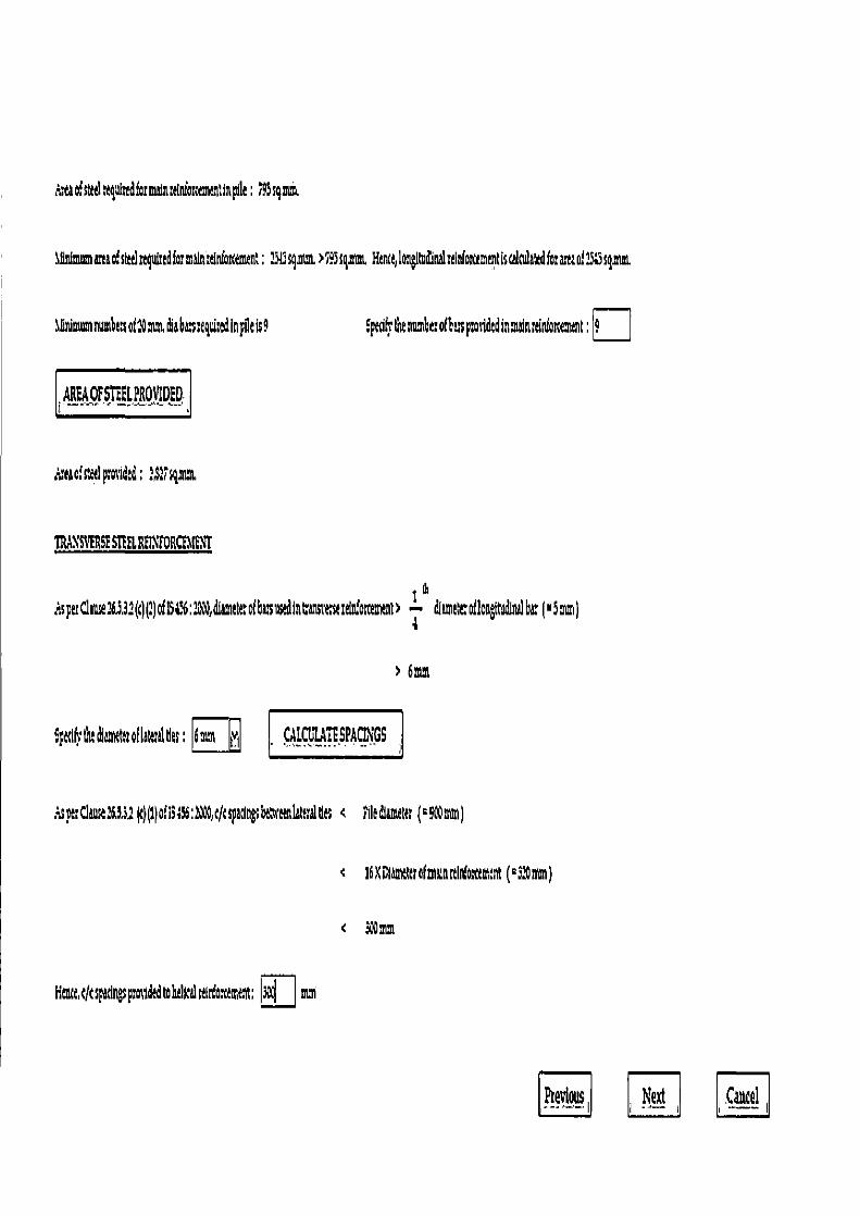
ntaofs,eelttgulndfsmain:ntosmnnunpile: i95cq,mñt
Gaiaumanaofsied 515sq im.>795sni, Hen, lonlmdinalrelnfo liscalNlaredforaraoiSSsgmm
%Iwm mnunshe;sol:Dram±abt :equimdinpilels9
Spedis the number ofbasspmddtdinnainrdniarceanns ;
AREAOFSIEELPROVlDED
A uof steel rod; :,S 7sgana~
IRAN SVERSE 51EEL REII EORCf.UENT
isperClaause~S,3?(cll•'lofi6u~d;:~b,d(amelerofbususedintansrrurdrloscemenl~ { WitoflongtSinalbe('9mm)
?6nm
Sp< diamthrfl6cerdtls; 6mnt f_t~U1,1____INGS
c t;Claus:63,3.1tl lofi5;l6:200 t/tsarings6cnrenlsera1tle < Fikthanseser (29Nmm)
< 16RCfanttterofrndottln(ouemenr (M3:Omm)
HnttltspadngsprolldtdrolbtdtcLrdotnt : ® mm
ihegfous . Neat Cancel
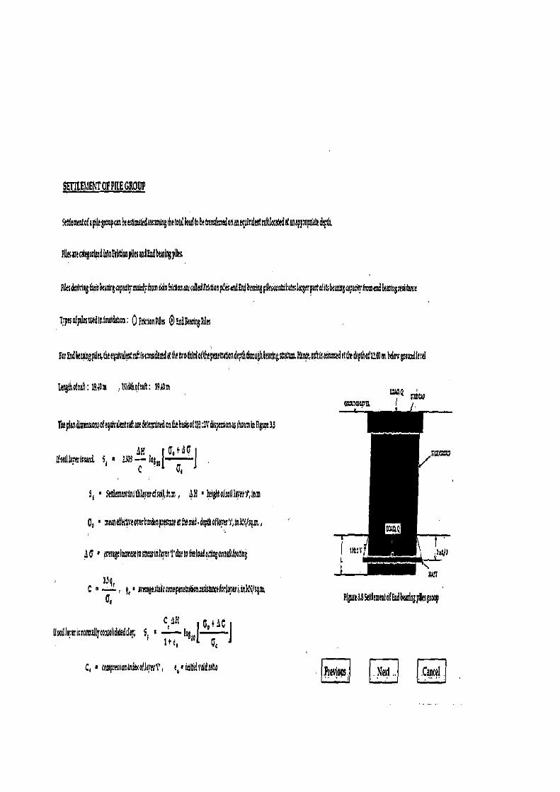
r3WQ m:.,~
Flgns!35lllammldf Fndbttdagputsgsoop
lhevloln j Nevi .. .Cancel .
ktticmantof spitegroupranfia ntlsrateda~~,ingdserofolloadfo brtransirmdohaAtgFiraladmRlocandaf aaappsapdate rlcpft
PursutcahgotipsdioloFtiidiooygnmdF¢d6tulagyJas
F~sdchicgda dca~ngnpa~lrmeaJ fromsldntncaa~u¢Adtrr5oap tm~dl dbemmgpdaio Ci6uhclagerpatolittbtdsngcpaatrA=Ca 6<armgmte
pasofpilakdlAfowdaErs: ojikGonPlles QFAd&aet ilea
forFndhanngptlrs,t ttgmealmtra&(storm&iSflthrolMrdafhhpanttratlen&pthSaughbtmingsteayg ,sit(saiA>mtdat(&dtptnofUWRMoa•growdlcrd
Fmgtlso(rel: ,lttdthofah: 19ADM
'Cpaylaadiminsiozsofegtra>aolrtaa dale;traradandtbasisofTN 4dispaaaonasshouniptlgwe33
tdG Nakt(ssand, Sr ' ~j'H C tr,
S r ^ 5ei& arirI'binrrO1J,im, JH ° hrighto(mgln'tt'I',IAm
pa ° r.melktraosrr6mdG~pnssg4trrS.dptholla}•rr't',1ak1/gm„
Q ° prergeSdteIAShtssIaZwer't'da fltbadacanganragkadng
C R ' , 4 ' mYUgestebsroaepastrrboausis~acak lni,inkusgm
S • — !o I
( cue+ 1G f
Qsopinaisnonrall ro;Aalldatrddar; . ~ — ,
Cl ° ceaspr tot(nd lkrert a,'I~tlaradtatla
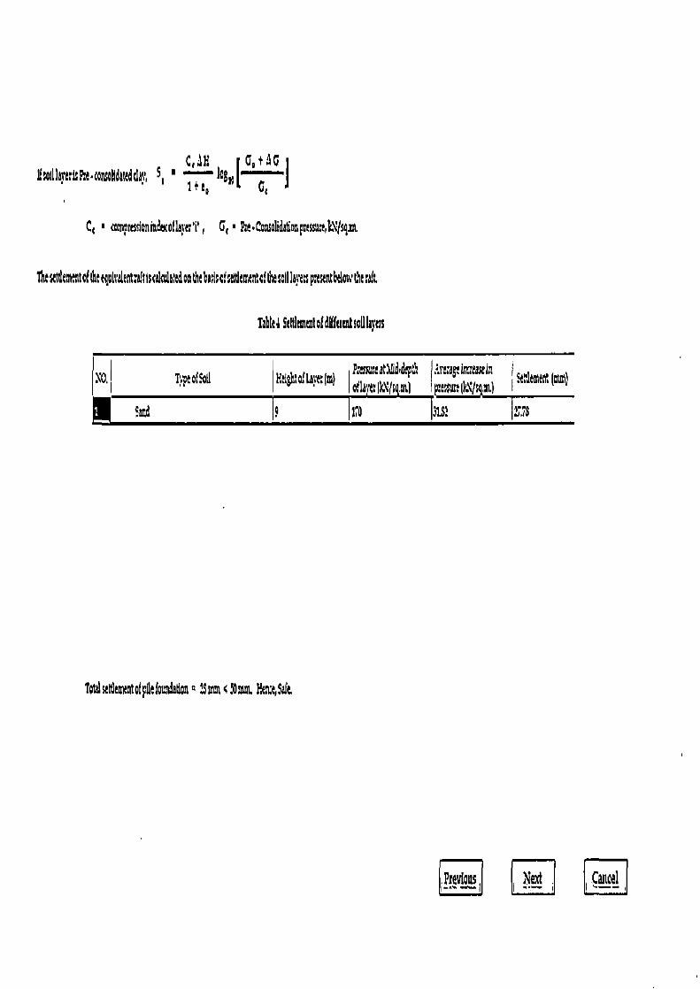
c,nH Go tAG U oI11k ttl:P•c°tisohdst°dclw, S, ° 1" }`~' I°Bso L G ~ I
° comprKSfoninncoflaec'i', G, lhe.Consolidationprnsu.e,k\1sgs
h2tf wtof61eQolcalt°t;tlscidiledootht6ads°fseld°cuetalt&SollIa4wpsesetltbdo. thasalt
Ta ka Sdtles°mt°fdlffamt soil lbyas
\0, Tvptof!od Hd tofLkve: m ~ (! Rasmeatllid~deplh oflarl:Ik\(s ,ml
.ire,agrinceasell I RW mt (mm) p:cssusalk\fs,u,l
9ud o lie 3151 2773
T°talutdeeuotofpdef°i.toa° 1S ottun, HZ Silt
Prwlus Next . Canal
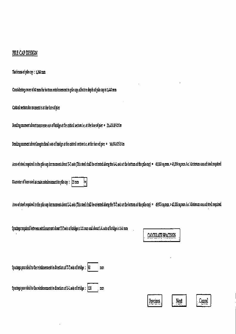
PILE CAP DESIGN
ibid ssofpdecap;
Consldsing cover of6ommforbo mrciti'a cementInpiecap,dfethredepthofptlecapls1" mm
Miticatsc onformomcntlsitthefL cfpla
PSlrtgmommtabouttrasuscmasicoThhdgcatthcaiticals cNonl.c,atthefaceofpAer a ?1 .63kim
Pen&ng moment abutlongitudlnda4sofbdgcatmeaidcd &aonta•atenc fete ofptec 16,63 )Nm
sxaoEsttclrlquictdlntbe pile capfo:momantaboutl.Taus (Id steel shall Leo thdalongthe14Ssat the bottomof the pllecap)• 63193sgmm,>4336 sr. t.&.\r1mumattaofstaduathed
Ctameterofbssusedasmln:elnfocementfnpaecap:l5 ~I
.,11of steel nquitedin the pile cap for moment about t1ads(Tis steel shall Leo ntedalongthet•Txdsat the botiomof the pilecap)a ;R3smm>63,396sgmm,It.\ sdmumoeaofsteelmquisad
SpadngstogaisedbehrennI cementshoatTTafcofbidgcis iii rim andabout1.6a4 ofb,Idgeis144mm fALfL1 mpkgqs
I
SpadagspsoiidcdtothertirdOmmG~tladls¢~oaolT•iausafb~dge; mm
:pacingspotidedtofherein(ar tindlraonofbladsofbddge; 110 mm
Previous Neil .Cancel
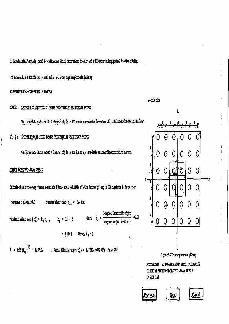
:9irm4abaisdecquallrspuedcctcdfs~magomi.ia ansitiskdiidciaedatINAOmmfnlon~lndtn~'ar doiiofbildgc
Lnu %dla,6!s sf3Ot r4ca:ausadashasl.ontottleInipcapto:01s6usstlng
WNIWBtt[10NMILESLVSR
5' 170Q St CASE!: itt~121IF dPEG1~1GOG15IDEfl{EC&R(CL5ECii01'OFSFtEAlt
Ypctlcra~d~atllstuueofQ9Xdfa~e&iofpdEle.yDruncrmmeout~d~ d~se<'tlon srdl'rontribnhib(uureattlnglnsluu,
Grit:. i1t41F1IF6?HE1rn011IDEi} CIN1G115ECnD10FSxL2
Pilaslcrdkdataba tDf09Xdfaa~4dpnaliammormoreWelhesxtlansrdlnotcmttlihutelnsluas.
CHECXiOR1WOWAT5NE4R
itlrelse~otiknc~a~ragsiceulslaandatadlstamecquitohal6ai'krff 4redip$upil6cap1.0.9:OmmfromkiA ofpicr
sfStc :L,9i:, W \amfnhiskwcIresstt)` O61JIa
length of St: side oI pier Podsslblastearstcss (t,)- ks tI , k s ■ u+ p1 sr m fl IengtlsoElasgsrndeoiplet °t,0
!4 1 Fknt4'k s '.1
° 023 (t'yl ` 1i$.\lPa ;, Pasndsfrbltshu sites It) a G27T4Y061 IPa ItcnaGI
NMI~s/
1 11111 1
E
Flgnse$STwo.tray shtuinpUttip
SOTh:RW1I,VEL%%3OV!DIAORIMADICAfl$ CaMCAL SIMON POR•1Rro .WAY SHEAR
R PK AP
s
5
s!
—I
—i
Pi44~9US,
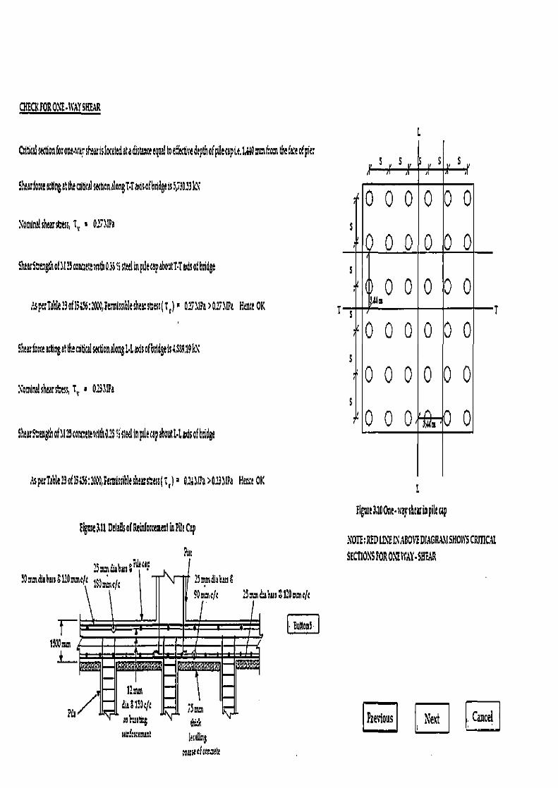
CHECK FOR 01'F. {VAY SHEAR
Xounishearsass, T,, I 0 1lPa
ShtartcoO!11arot~:tltss7dto?S°isleelinpietapabouWt icofb7dgt
L
s ,s,s iI
1 1 1 1, 1
1 I / 1 1 1 ills 1 f 1
Ica$ 1
Citltal secCOlfo: oat ,rarshtarislaattdaladistdraetycal beitcttie depth of pOttapLt 14 Qnun(mas tnefate of plc
Shtarfone ittlsgathaidt is 5,73033 LX
ShttsSyettgtis of 11:7 coat,t;t sstds O.is 5 sled in pdt tap about T•T ads of badgt S
isptTa1t:3o{1i;l6::000,FtmIsD6lasheasCtss(t) ZIPa>02T11pa Heitz OK
Shtacfaste attlngaldtttdtitalsatlonalongl Laasofbsidgtis{SS9,19kC s
Xo~inalshearsba, t V, . 0i111a
—T
upe Tb1 i3o!1356;:00,FmVssibleshta•sCtss(t) 02;11Pa>Oi lIPa Htn;t OK
figure all Ddails of B f orcemtnl b Pot Cap
Pur
?i~tdubusa;`'~ cep m1i0neft 1~nacJ~ ?7mmdia6us8
L \-
90mmeJ; 3duhrn12OncJt
; I 'J •Button!
t'AOmm
I
Figut 310 Oat • wq shw is pile ap
NOTE: RFD LZE L\ AB01 DIMGRX11
SECFL01 S FOR OXt WAY • SH¢AR
/U 11 du61lD;ft iSmm arkurtc~ tky urr?ar,;~nt lor~g
IFt roarucfroraata
EE Next rc Jantd
6.4 CONCLUSIONS
The analysis and design of well foundation and pile foundation for the provided details have
been performed. The software generates the output of result with diagrammatic representation.
All the guide line are given to user where necessary. The output of the software is compared with
the long hand calculations of the problem. The output of software resemble with the results of
long hand calculations. Hence, it is concluded that the software provides accurate results and
with in the short period of time.
1281Page

CHAPTER 7
CONCLUSIONS 7.1 CONCLUSIONS
The following conclusions are drawn on the basis of the software development work ,related to analysis and design of bridge structures carried out for this thesis.
1) It is possible to develope user friendly, interactive and handy computational tools for the
analysis and design of bridge sub-structure sing readily available software platforms. 2) The proposed software can be particularly useful for the design optimisation of bridge
foundations particularly in the context of unexpected sub-soil conditions encountered
during construction. The program equips design engineers with a handy and convenient
software tool to quickly reconfigure and analyse and design bridge foundation in
response to field conditions for best performance and economy. 7.2 SCOPE FOR FURTHER WORK
The capabilities of the software developed can be further expanded to, include the
following additional aspects of substructure analysis and design:
1) The superstructure analysis for continuous spans on different types of bearings and of
different configuration can be included so as to broad-base the scope of application of the
software.
2) Options for pier design can be included for varying geometry pier. Option for analysis and design of pier cap of hammer-head type of piers using strut-and-tie models can be
included in the software.
3) Options for different arrangement and layouts of pile in a pile group can be included in
the software
4) The software can be interfaced with standard CAD packages like AUTOCAD for
generating detailing and working drawings of the bridge sub-structure.
129 1 Page
CHAPTER 8
REFERENCES 1. IS: 456 2000; "Plain and Reinforced Concrete — Code of Practice (Fourth Revision) ";
BIS, New Delhi. 2. IS: 875 (Part 3) — 1987; "Code of Practice for Design Loads (Other than Earthquake) for
buildings and structures"; BIS, New Delhi. 3. IS: 2911 (Part I/Sec 2) — 1979; "Code of Practice for Design and Construction of Pile
Foundations, Concrete Piles, Bored Cast In-situ Piles (First Revision)'; BIS, New Delhi. 4. IS: 2911 (Part III) — 1980; "Code of Practice for Design and Construction of Pile
Foundations, Under-reamed Piles (First Revision) "; BIS, New Delhi. 5. IS. 3955 - 1967; "Code of Practice for Design and Construction of Well Foundations";
BIS, New Delhi.
6. IRC: 6 — 2000; "Standard specifications and code of practice for road bridges, Section: II, Loads and Stresses (Fourth Revision) "; The Indian Road Congress, New Delhi.
7. IRC: 45 — 1972; "Recommendations for estimating the resistance of soil below the maximum scour level in the design of well foundations of bridges "; The Indian Road Congress, New Delhi.
8. IRC: 78 — 2000; "Standard specifications and code of practice for road bridges, Section: VI1, Foundations and Substructure "; The Indian Road Congress, New Delhi.
9. SP: 16 (1980); "Design Aids For Reinforced Concrete to IS: 456-1978"; BIS, New Delhi.
10. SP: 34 (S & T) (1980); "Hand Book on Concrete Reinforcement and.Detailirig"; BIS, New Delhi. .
11. Saran, S. (1996); "Analysis and Design of Substructure - Limit State Design (Second Edition)'; Oxford & IHB Publishing Co. Pvt. Ltd., New Delhi.,
12. Victor, D. J. (1973); "Essentials of Bridge Engineering (F(th Edition) "; Oxford & IBH Publishing Co. Pvt. Ltd., New Delhi.
13. Jain, A. K. (1993); "Reinforced Concrete — Limit State Design (Fourth Edition) "; Nem Chand & Bros., Roorkee, Fourth Edition.
14. Pillai, S. U. & Menon, D. (1999); "Reinforced Concrete Design "; Tata McGraw Hill, New Delhi."
130 I P a g e
15. Das, B. M. (2004); "Principles of Foundation Engineering (Fifth Edition)"; Brook/Coles Pub. Co., CA.
16. Singh, V. (1981); "Wells and Caissons (Second Edition) "; Neni Chand & Bros., Roorkee
17. Prakash, S. (1979); "Analysis and Design of Foundations And Retaining Structures";
Santa Prakashan, New Delhi. 18. Arora, K. R. (2003); "Soil Mechanics And Foundation Engineering (Sixth Edition) ";
Standard Publishers Distributors, New Delhi.
19. Ramamrutham, S. (2005); . "Theory of Structure (Eighth Edition) "; Dhanpat Rai
Publishing Company (P) Ltd., New Delhi.
20. Holzner, S. (2005); "Visual Basic .Net Programming Black Book"; Paraglyph Press,
USA.
21. Terzaghi, K. And Peck, R. B. (1976); "Soil Mechanics in Engineering Practice "; John
Wiley and Sons Inc., New York.
22. De Beer, E. And Marten (1957); "Method of Computation on Upper limit for the
Influences of Heterogeneity of Sand Layers in the Settlement of Bridges"; Proc. 4th Int.
Conf. On SMFE, London, Vol. 1.
23. www.iricen.gov.in, website of Indian Railway Institute of Civil Engineering, Pune.
131 Page
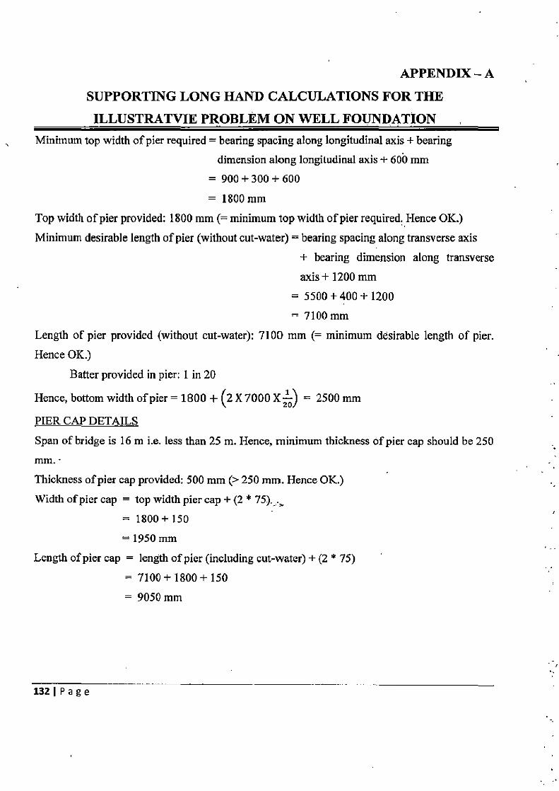
APPENDIX — A SUPPORTING LONG HAND CALCULATIONS FOR THE
ILLUSTRATVIE PROBLEM ON WELL FOUNDATION Minimum top width of pier required = bearing spacing along longitudinal axis + bearing
dimension along longitudinal axis + 600 mm
= 900+300+ 600
= 1800 mm Top width of pier provided: 1800 mm (= minimum top width of pier required. Hence OK.)
Minimum desirable length of pier (without cut-water) = bearing spacing along transverse axis
+ bearing dimension along transverse
axis+ 1200 mm = 5500 t400-I-1200 = 7100 mm
Length of pier provided (without cut-water): 7100 mm (= minimum desirable length of pier. Hence OK.)
Batter provided in pier: 1 in 20
Hence, bottom width of pier = 1800 + (2 X 7000 x) = 2500 mm
PIER CAP DETAILS
Span of bridge is 16 m i.e. less than 25 m. Hence, minimum thickness of pier cap should be 250 mm.
Thickness of pier cap provided: 500 mm (> 250 mm. Hence OK.)
Width of pier cap = top width pier cap + (2 * 75).> = 1800+ 150 = 1950 mm
Length of pier cap = length of pier (including cut-water) + (2 * 75)
= 7100+1800+150
= 9050 mm
1321 Page
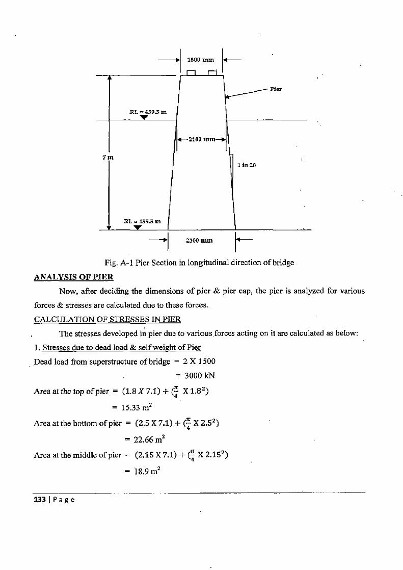
1800 nun
2500 inm
Fig. A-1 Pier Section in longitudinal direction of bridge
ANALYSIS OF PIER Now, after deciding the dimensions of pier & pier cap, the pier is analyzed for various
forces & stresses are calculated due to these forces.
CALCULATION OF STRESSES IN PIER
The stresses developed in pier due to various forces acting on it are calculated as below:
1. Stresses due to dead load & self weight of Pier
Dead load from superstructure of bridge = 2 X 1500 11177r•I
Area at the top of pier = (1.8 X 7.1) + (4 X 1.82)
= 15.33 m2
Area at the bottom of pier = (2.5 X 7.1) + (4 X 2.52)
= 22.66 m2
Area at the middle of pier = (2.15 X 7.1) + (4 X 2.152)
= 18.9 m2
133 Page
Pier Volume = Pier height (Area at the top of pier + Area at the bottom of pier + 4 X
Area at the middle of pier )
= 6(15.33 +22.66+4X18.9)
= 132.52m3
Pier cap volume = 9.05 X 1.95 X 0.5
= 8.82 m3 Total volume = 132.52 + 8.82 = 141.34 m3
Hence, total weight of pier & pier cap = 141.34 X 25 = 3533 kN
:• Stresses due to dead load of superstructure & weight of pier Sc pier cap = 3533+3000 22.66
= 288.34 kN/m2
2. Stresses due to eccentricity of live load
Moment of Inertia about X axis i.e. T-T axis of bridge, I,~ 7.1X2.53 + rrX2.5 ^ 4
12 64
= 11.16 m4
Moment of Inertia about Y axis i.e. L-L axis of bridge, Iy,
2.5X7.13+2
lrX2.54 +7rX1.252 X /7_1 + 4X1.25 2
12 [ 128 2 \ 2 3a ]
= 158.22 m4
(a) Due to eccentric live load about transverse axis of bridge
Vertical live load on pier, producing maximum stress about transverse axis = 763 kN, &
Moment due to live load eccentricity about transverse axis of bridge, producing maximum stress
about transverse axis = 180 kNm
:• Stress at the base of pier due to eccentricity of live load about transverse axis _ M P+xx y
A 1xx
22.66 +(1806
/
X1.251
= 53.84 kN/m2 or 13.57 kN/m2
(b) Due to eccentric live load about longitudinal axis of bridge
Vertical live load on pier, producing maximum stress due about longitudinal axis = 395 kN,
1341Page
Moment due to live load eccentricity about transverse axis of bridge, producing maximum
about longitudinal axis = 969 kNm
:. Stress at the base of pier due to eccentricity of live load about longitudinal axis
= A P+_MYYX
Iyy
395 + ( 969 X 4.8) 22.66 1158.22
= 46.85 kN/m2 or -11.94 kN/m2
NOTE: The stresses acting at the base of pier due to live load eccentricity is calculated with the
use of program prepared in Microsoft Excel Worksheet.
3. Stresses due to longitudinal forces
(a) Due to tractive effort or braking forces orces
Braking effect is invariably greater than tractive effort. Hence, braking effort is considered.
Longitudinal force of Class A load = 0.2 X 486 X 2
= 194.4 kN
Moment at the base = 194.4 X 11
= 2138 kNm
Stress at the base of pier due to braking effort = ± 1xx
+2138 %1.25 - 11.16
= ±239.46 kN /m2
(b) Due to resistance at bearings
Coefficient of friction on the left side of bearing = 0.05
Coefficient of friction on the right side of bearing (reducing 5%) = 0.0475
Assume the combination of dead load & live load acting on the left side bearing and dead load
on right side bearing
Maximum live load reaction acting on the left side bearing = 648 kN
(as calculated from the program based on Excel Worksheet)
Total resistance to sliding on the left side bearing = 0.05 X (1500 + 648) = 107 kN &
Total reacting on the right side bearing = 0.0475 X 1500 = 71.25 kN
:• Unbalanced force = 36 kN
Moment due to unbalanced force at the base of pier = 36 X 7.8 = 282 kNm
1351Page
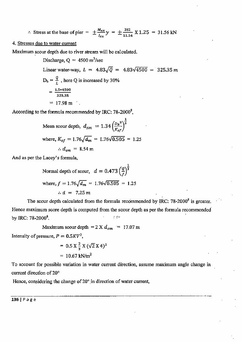
• Stress at the base of pier = ±
= ± 182 X 1.25 = 31.56 kN lxx
4. Stresses due to water current
Maximum scour depth due to river stream will be calculated.
Discharge, Q = 4500 m3/sec
Linear water-way, L = 4.83 = 4.83V4500 = 325.35 in
Db = 4 , here Q is increased by 30%
_ 1.5.4500
325.35
= 17.98m
According to the formula recommended by IRC: 78-2000$, I
/ 62 Mean scour depth, dsm = 1.34 I 3
where, KS! = 1.76J = 1.76 0.505 = 1.25
.'.dsm = 8.54 m
And as per the Lacey's formula, 1
Normal depth of scour, d = 0.473 (Q)3 f
where, f = 1.76 dT„ = 1.76-10.505 = 1.25
:. d = 7.25 m
The scour depth calculated from the formula recommended by IRC: 78-20008 is greater. Hence maximum score depth is computed from the scour depth as per the formula recommended by IRC: 78-20008. '
Maximum scour depth = 2 X dsm = 17.07 m
Intensity of pressure, P = 0.5KV 2 ,
= 0.5X2X(JX4)2
= 10.67 kN/m2
To account for possible variation in water current direction, assume maximum angle change in
current direction of 20°
Hence, considering the change of 200 in direction of water current,
136jPage
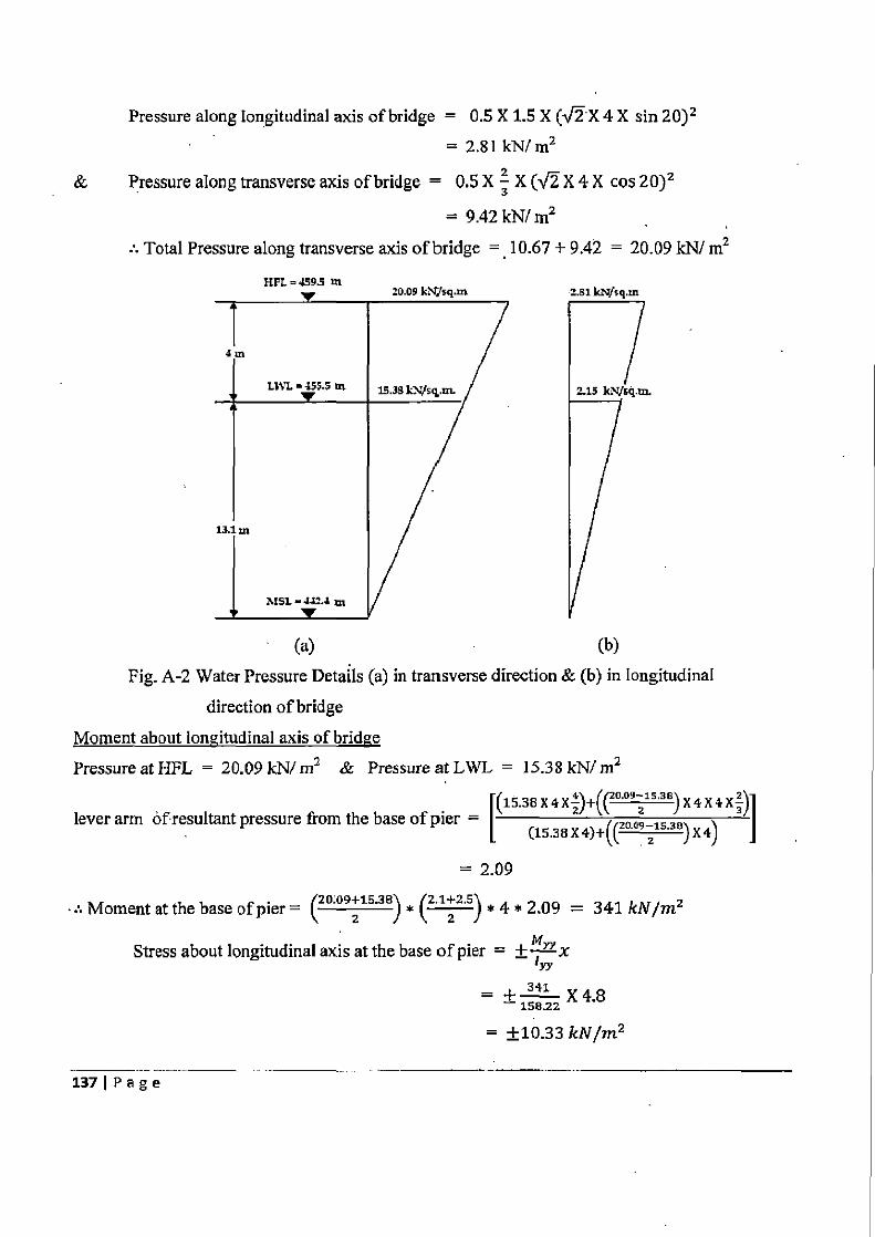
Pressure along Iongitudinal axis of bridge = 0.5 X 1.5 X (V X 4 X sin 20)2
= 2.81 kN/ m2
& Pressure along transverse axis of bridge = 0.5 X 3 X (v X 4 X cos 20)2
= 9.42 kN/ m2
• Total Pressure along transverse axis of bridge = 10.67 + 9.42 = 20.09 kN/ m2
HFL=4 95 in an nn L\H......
(a)
(b)
Fig. A-2 Water Pressure Details (a) in transverse direction & (b) in longitudinal
direction of bridge
Moment about longitudinal axis of bridge
Pressure at HFL = 20.09 kN/ m2 & Pressure at LWL = 15.38 kN/ m2
F(15.38X4X2)+((20.09 15.36)X4X4X3) lever arm ofresultant pressure from the base of pier — Zo.-.3e (15.38X4}+(~ o9 Z~s )X4)
= 2.09
:• Moment at the base of pier = (20:09+15.38) * (2A+2.$) * 4 * 2.09 = 341 kN/m2
Stress about longitudinal axis at the base of pier = ±-x rY
— 158.22 X 4.8
= ±10.33 kN/m2
2.81
1371Page
Moment about transverse axis of bridge Pressure at HFL = 2.81 kN/ m2 & Pressure at LWL = 2.15 kN/ m2
[(2.15 X4XZ}+{ (&B122.151 X 4 X 4X31 lever arm of resultant pressure from the base of pier =
(2.15 X4) \+1 2.81-2.19) X 4) ] \\ z 1
= 2.09
Moment at the base of pier = (2.15 +2.81) * (9.2:9.6) * 4 * 2.09 = 195 kN/m2
Stress about transverse axis at the base of pier = ± M x y
=+--X125 - 11.16 _ ±21.79 kN/m2
5. Stresses due to effect of buoyancy
Width of pier at HFL = 2.1 m
Area of pier at the HFL = (2.1 X 7.1) + (¢ X 2.12) = 18.37 m2
Hence, submerged volume of pier = 6 (18.37'+ 22.66 + 4 X 20.52) = 82 m3
Net buoyant force = 82 X 10 X 0.15 = 123 kN
Stress due to buoyant force = - A zz 66 = -5.43 kN/m2
6. Stresses due to wind load
(a) Area of superstructure as seen in elevation = 70 m2
The height of exposed surface of bridge structure, when water level is at HFL = 5.8 m
For 5.8 m, the intensity of wind load is taken as 0.72 kN/ m2
Hence, Total wind force = 70 X 0.72 = 50.4 kN/ m2 (b) Considering the wind load acting on moving live load having magnitude of 3 kN/m & acting
at 1.5 m above road way,
Wind force against the moving load = 16 X 3 = 48 kN
(c) Total wind force as in (a) & (b) above = 48 + 50.4 = 98.4 kN
(d) Minimum limiting load on deck at 4.5 kN/m = 16 X 4.5 = 72 kN
(e) Minimum limiting load on at 2.4 kN/m2 on exposed surface = 2.4 X 70 = 168 kN
Since force in (e) is maximum, this will be adopted. This force will be assumed to act at the
bearing level for the purpose of calculating the moment at the base of pier.
1381Page
Moment at the base of pier = 168 X 8.8 = 1478.4 kNm
Stress at the base of pier = ± x rr
+1478.4 X4.8 — 158.22
= ±44.85 kN/m2
7. Stresses due to seismic effect (a) Seismic moment acting at the base of pier due to the masses of bridge component & live load
Seismic moment at the base of pier, due to mass of pier
= 0.1X 25X 7(15.33 +(4X18.9X z)+0)
= 1084 kNm Maximum live load acting on the pier, for Class A train = 791 kN
(as calculated from the program coded in Excel Worksheet)
Total dead load of superstructure = 2 X 1500 = 3000 kN
& Mass of pier cap = 221 kN Hence, total seismic moment due to mass of bridge components
= ((791 X 11) + (3000 X 8.8)+(221 X 7.25)) X 0.1 + 1084
= 4755 kNm .. Total seismic moment due to mass of pier about longitudinal axis = 4755 kNm &
Total seismic moment due to mass of pier about transverse axis = ((3000X8.8)+(221 X7.25))X0.1+,1084
= 3885 kNm
(b) Moment due to hydrodynamic forces For hydrodynamic force along longitudinal direction
H = 4 m, a = 4.8 Therefore, Q = 0.83
For seismic zone II, ah = 0.075
For value of H = 0.83, Co = 0.33 & 2 = 0.39 a
F = CaahyWrra2H
=0.33X0.075X9.81X4.82 X 4
=71kN
1391 Page
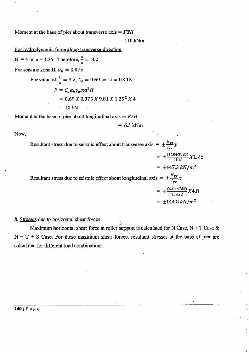
Moment at the base of pier about transverse axis = FzH = 110kNm
For hydrodynamic force along transverse direction
H = 4 m, a = 1.25 Therefore, y = 3.2 a
For seismic zone II, ah = 0.075
For value of H = 3.2, Co = 0.69 & z = 0.415 a
F = CnahYwma2 H
= 0.69 X 0.075 X 9.81 X 1.252 X 4
= 10kN
Moment at the base of pier about longitudinal axis = FzH
= 6.5 kNm Now,
Resultant stress due to seismic effect about transverse axis = ±-1---y xx
_ +(110+seas)X1.25 11.16
= ±447.3 kN/m2
Resultant stress due to seismic effect about longitudinal axis = ± Trr
+ (6.5+4755) X4.8 158.22
= ±144.8 kN/m2
8. Stresses due to horizontal shear forces
Maximum horizontal shear force at roller support is calculated for N Case, N + T Case &
N + T + S Case. For these maximum shear forces, resultant stresses at the base of pier are
calculated for different load combinations.
140 I Page
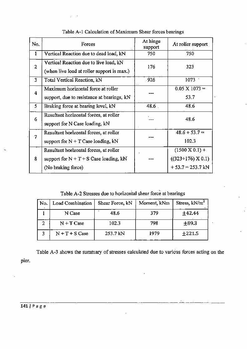
Table A-1 Calculation of Maximum Shear forces bearings
No. Forces At hinge At roller support support I Vertical Reaction due to dead load, kN 750 750
Vertical Reaction due to live load, kN 2 176 323
(when live load at roller support is max.)
3 Total Vertical Reaction, kN 926 1073
Maximum horizontal force at roller 0.05 X 1073 = 4 ---
support, due to resistance at bearings, kN 53.7
5 Braking force at bearing level, kN 48.6. 48.6
Resultant horizontal forces, at roller 6 --- 48.6
support for N Case loading, kN
Resultant horizontal forces, at roller 48.6 + 53.7 = 7 ---
support for N + T Case loading, kN 102.3
Resultant horizontal forces, at roller (1500 X 0.1) +
8 support for N + T + S Case loading, kN --- ((323+176) X 0.1)
(No braking force) + 53.7 = 253.7 kN
Table A-2 Stresses due to horizontal shear force at bearings
No. Load Combination Shear Force, kN Moment, kNm Stress, kN/m2
1 N Case 48.6 379 ±42.44
2 N +T Case 102.3 798 ±89.3
3 N+T+S Case 253.7 kN 1919 ±221.5
Table A-3 shows the summary of stresses calculated due to various forces acting on the pier
141 I Page
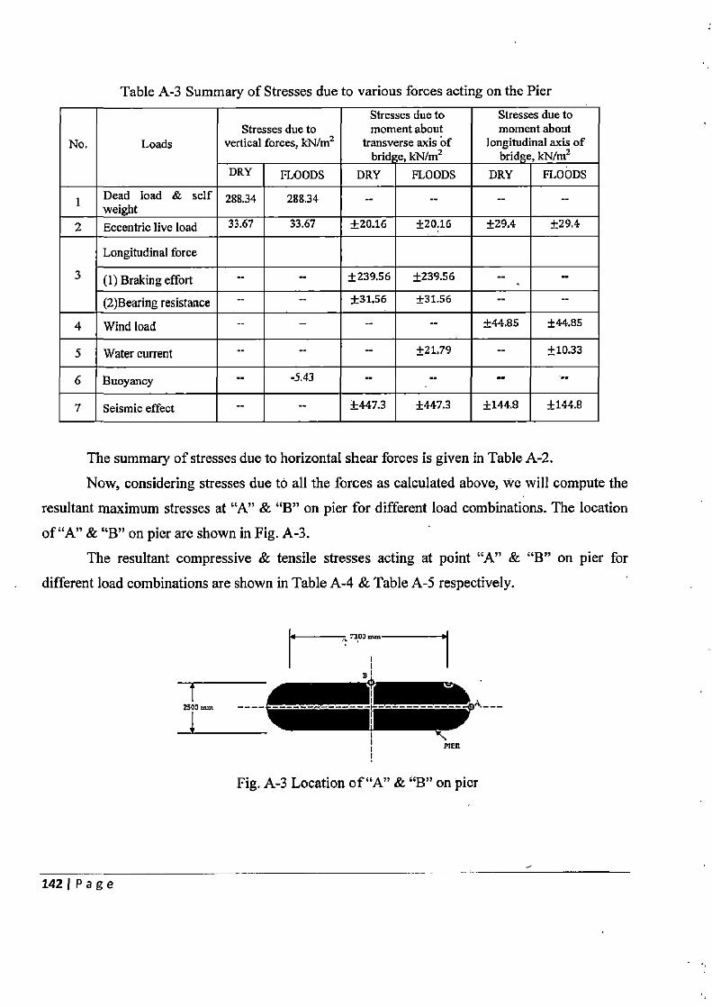
Table A-3 Summary of Stresses due to various forces acting on the Pier
No. Loads Stresses due to
vertical forces, kN/m2
Stresses due to moment about
transverse axis of bridge, kN/m2
Stresses due to moment about
longitudinal axis of bridge, kN/m2
DRY FLOODS DRY FLOODS DRY FLOODS 1 Dead load & self
weight 288.34 288.34 -- -- -- --
2 Eccentric live load 33.67 33.67 ±20.16 ±20.16 ±29.4 ±29.4
Longitudinal force
3 (1) Braking effort -- •- ±239.56 ±239.56 --
(2)Bearing resistance -- -- ±31.56 ±31.56 -- --
4 Wind load -- -- -- -- ±44.85 ±44.85
5 Water current — ±21.79 -- ±10.33
6 Buoyancy -5.43 •-
7 Seismic effect -- ±447.3 ±447.2 ±144.9 ±144.8
The summary of stresses due to horizontal shear forces is given in Table A-2.
Now, considering stresses due to all the forces as calculated above, we will compute the
resultant maximum stresses at "A" & `B" on pier for different load combinations. The location
of "A" & `B" on pier are shown in Fig. A-3.
The resultant compressive & tensile stresses acting at point "A" & `B" on pier for
different load combinations are shown in Table A-4 & Table A-5 respectively.
2300 m,,t --
I
Fig. A-3 Location of "A" & `B" on pier
1421 Page
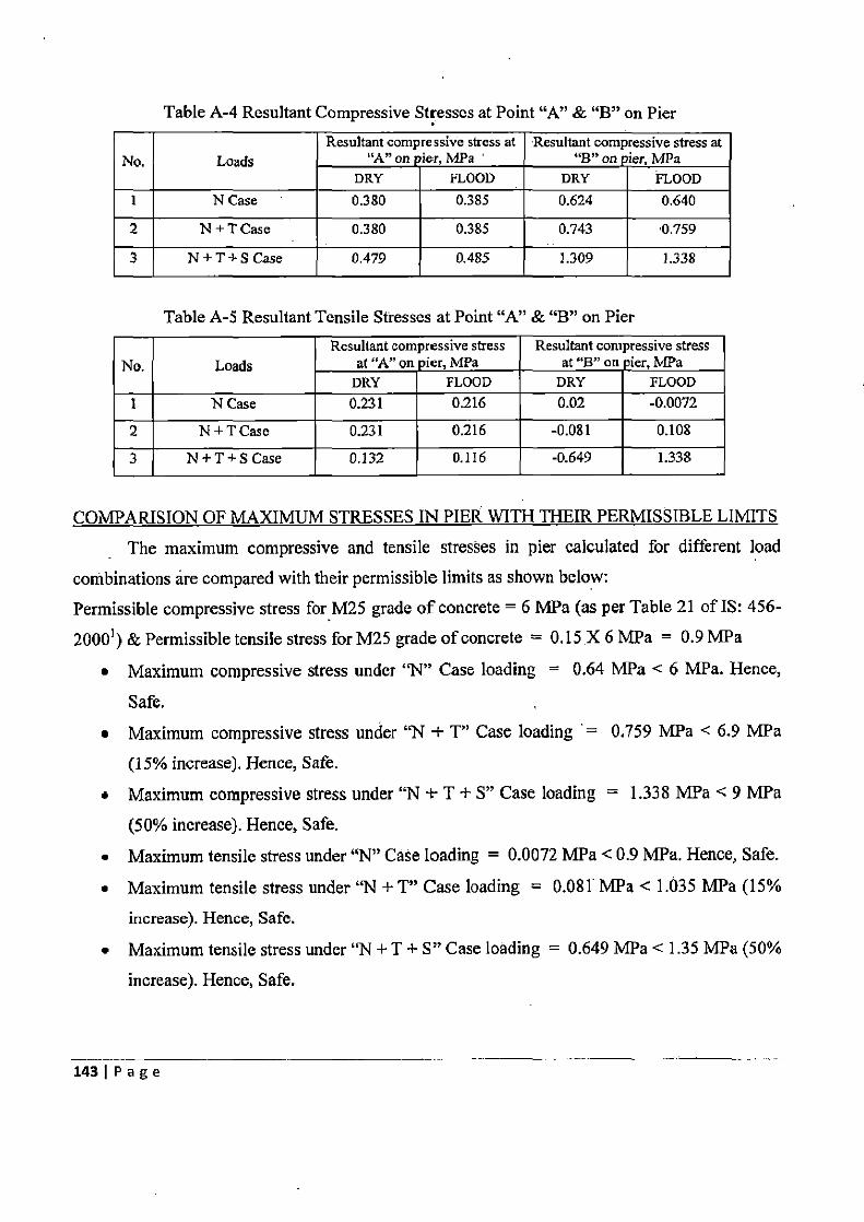
Table A-4 Resultant Compressive Stresses at Point "A" & `B" on Pier
No. Loads Resultant compressive stress at
"A" on ier, MPa ' Resultant compressive stress at
`B" on ier, MPa DRY FLOOD DRY FLOOD
1 N Case 0.380 0.385 0.624 0.640
2 N + T Case 0.380 0.385 0.743 0.759
3 N + T + S Case 0.479 0.485 1.309 1.338
Table A-5 Resultant Tensile Stresses at Point "A" & `B" on Pier
No. Loads Resultant compressive stress
at "A" on pier,MPa Resultant compressive stress
at `B" on ier, MPa DRY FLOOD DRY FLOOD
1 N Case 0.231 0.216 0.02 -0.0072
2 N + T Case 0.231 0.216 -0.081 0.108
3 N + T + S Case 0.132 0.116 -0.649 1.338
COMPARISION OF MAXIMUM STRESSES IN PIER WITH THEIR PERMISSIBLE LIMITS The maximum compressive and tensile stresses in pier calculated for different load
combinations are compared with their permissible limits as shown below: Permissible compressive stress for M25 grade of concrete = 6 MPa (as per Table 21 of IS: 456-2000') & Permissible tensile stress for M25 grade of concrete = 0.15 X 6 MPa = 0.9 MPa
• Maximum compressive stress under "N" Case loading = 0.64 MPa < 6 MPa. Hence,
Safe.
• Maximum compressive stress under "N + T" Case loading = 0.759 MPa < 6.9 MPa (15% increase). Hence, Safe.
• Maximum compressive stress under "N + T + S" Case loading = 1.338 MPa < 9 MPa (50% increase). Hence, Safe.
• Maximum tensile stress under "N" Case loading = 0.0072 MPa < 0.9 MPa. Hence, Safe.
• Maximum tensile stress under "N + T" Case loading = 0.081 MPa < 1.035 MPa (15%
increase). Hence, Safe.
• Maximum tensile stress under "N + T + S" Case loading = 0.649 MPa < 1.35 MPa (50%
increase). Hence, Safe.
143 I P a g e
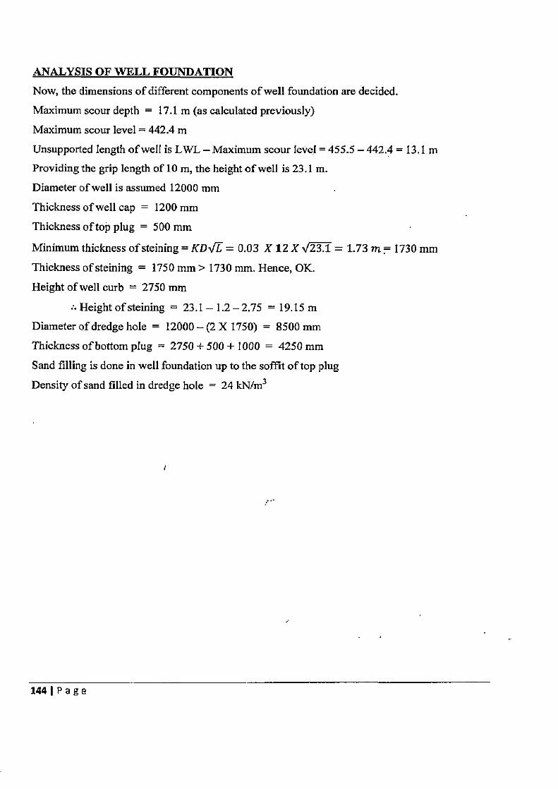
ANALYSIS OF WELL FOUNDATION
Now, the dimensions of different components of well foundation are decided.
Maximum scour depth = 17.1 m (as calculated previously)
Maximum scour level = 442.4 m
Unsupported Iength of wel l is LWL — Maximum scour level = 455.5-442.4 = 13.1 m
Providing the grip length of 10 m, the height of well is 23.1 m.
Diameter of well is assumed 12000 mm
Thickness of well cap = 1200 mm
Thickness of top plug = 500 mm
Minimum thickness of steining = KDi/E = 0.03 X 12 X V23.1 = 1.73 in = 1730 mm
Thickness of steining = 1750 mm > 1730 mm. Hence, OK.
Height of well curb = 2750 mm
• Height of steining = 23.1-1.2-2.75 = 19.15 m
Diameter of dredge hole = 12000 —(2 X 1750) = 8500 mm
Thickness of bottom plug = 2750 + 500 + 1000 = 4250 mm
Sand filling is done in well foundation up to the soffit of top plug
Density of sand filled in dredge hole = 24 kN/m3
144IPage
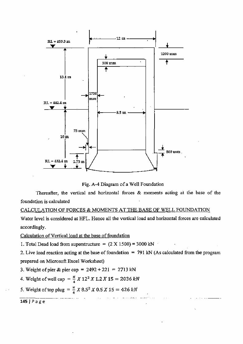
L RL=335,3m
Fig. A-4 Diagram of a Well Foundation
Thereafter, the vertical and horizontal forces & moments acting at the base of the
foundation is calculated
CALCULATION OF FORCES & MOMENTS AT THE BASE OF WELL FOUNDATION
Water level is considered at HFL. Hence all the vertical load and horizontal forces are calculated
accordingly.
Calculation of Vertical load at the base of foundation
1. Total Dead load from superstructure = (2 X 1500) = 3000 kN
2. Live load reaction acting at the base of foundation = 191 kN (As calculated from the program
prepared on Microsoft Excel Worksheet)
3. Weight of pier & pier cap = 2492+221 = 2713 kN
4. Weight of well cap = 4 X 122 X 1.2 xis = 2036 kN
5. Weight of top plug = 4 X 8.52 X 0.5 X 15 = 426 kN
145 Page
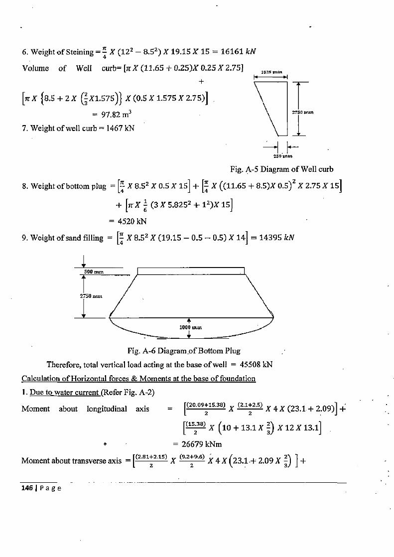
6. Weight of Steining = 4 X (122 _8.52) X 19.15115 = 16161 kN
Volume of Well curb= [7rX (11.65 + 0.25)X 0.25 X 2.75] ins mm
[7r X {8.5 + 2 X (2 X1.575)} X (0.5 X 1.575 X 2.75)]
= 97.82m3 7. Weight of well curb = 1467 kN
• :50 treat
Fig. A-5 Diagram of Well curb
8. Weight of bottom plug = [4 X 8,52 X 0.5 X 15] + [4 X ((11.65 + 8.5)X 0.5)2 X 2.75 x is]
+ [7rX 6 (3 X 5.8252 + 12)X 15]
= 4520 kN
9. Weight of sand filling = [4 X 8.52 X (19.15 — 0.5 — 0.5) X 14] = 14395 kN
508 mm
2750 mm
Fig. A-6 Diagram of Bottom Plug Therefore, total vertical load acting at the base of well = 45508 kN
Calculation of Horizontal forces & Moments at the base of foundation
1. Due to water current (Refer Fig. A-2)
Moment about longitudinal axis = ((20.09+15.38) X (2.1+2.5) X 4K (23.1 + 2:09)1 +
[(15.38) X (10+13.1X X 12 X 13.1]
b = 26679 kNm
Moment about transverse axis = r(2'B1Z2.15) X (9.229.6) X 4 X (23.1± 2.09 X 3) ] +
146IPage
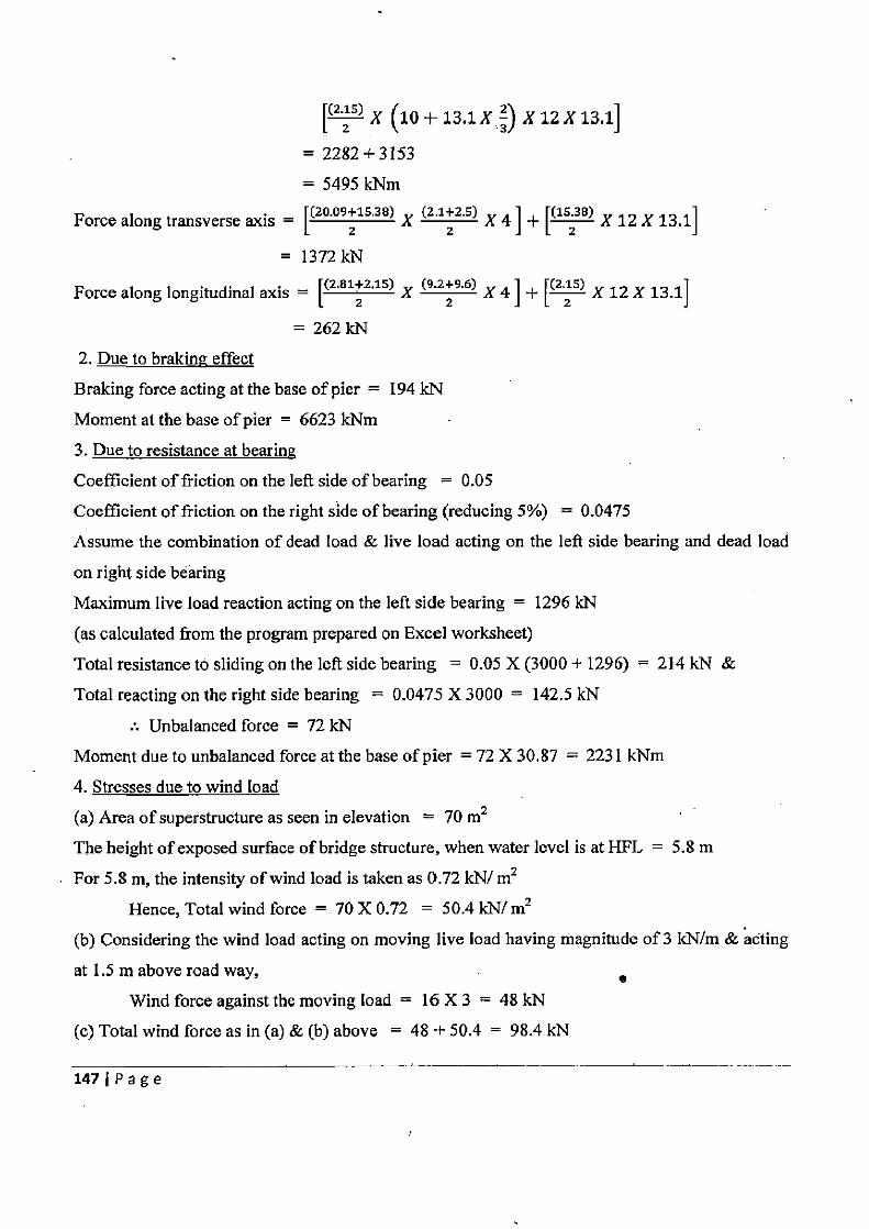
[(2.15) X (10+13.1X 3) X 12X 13.1]
= 2282+3153
= 5495 kNm
Force along transverse axis = [20.09+15.381 X (2.1+2.5) X 4 ]
+ [(15;381 X 12 X 13.1]
E3R 13~► 9i•I
Force along longitudinal axis = [(2.81+2.15) X (9 229 6) X 4 ] + [(25) X 12 X 13.1]
= 262 kN
2. Due to braking effect
Braking force acting at the base of pier = 194 kN
Moment at the base of pier = 6623 kNm
3. Due to resistance at bearing
Coefficient of friction on the left side of bearing = 0.05
Coefficient of friction on the right side of bearing (reducing 5%) = 0.0475
Assume the combination of dead load & live load acting on the left side bearing and dead load
on right side bearing
Maximum live load reaction acting on the left side bearing = 1296 kN
(as calculated from the program prepared on Excel worksheet)
Total resistance to sliding on the left side bearing = 0.05 X (3000 + 1296) = 214 kN &
Total reacting on the right side bearing = 0.0475 X 3000 = 142.5 kN
:. Unbalanced force = 72 kN
Moment due to unbalanced force at the base of pier = 72 X 30.87 = 2231 kNm
4. Stresses due to wind load
(a) Area of superstructure as seen in elevation = 70 m2
The height of exposed surface of bridge structure, when water level is at HFL = 5.8 m
For 5.8 m, the intensity of wind load is taken as 0.72 kN/ m2
Hence, Total wind force = 70 X 0.72 = 50.4 IN/m2
(b) Considering the wind load acting on moving live load having magnitude of 3 kN/m & acting
at 1.5 in above road way, I Wind force against the moving load = 16 X 3 = 48 kN
(c) Total wind force as in (a) & (b) above = 48 + 50.4 = 98.4 kN
1471Page
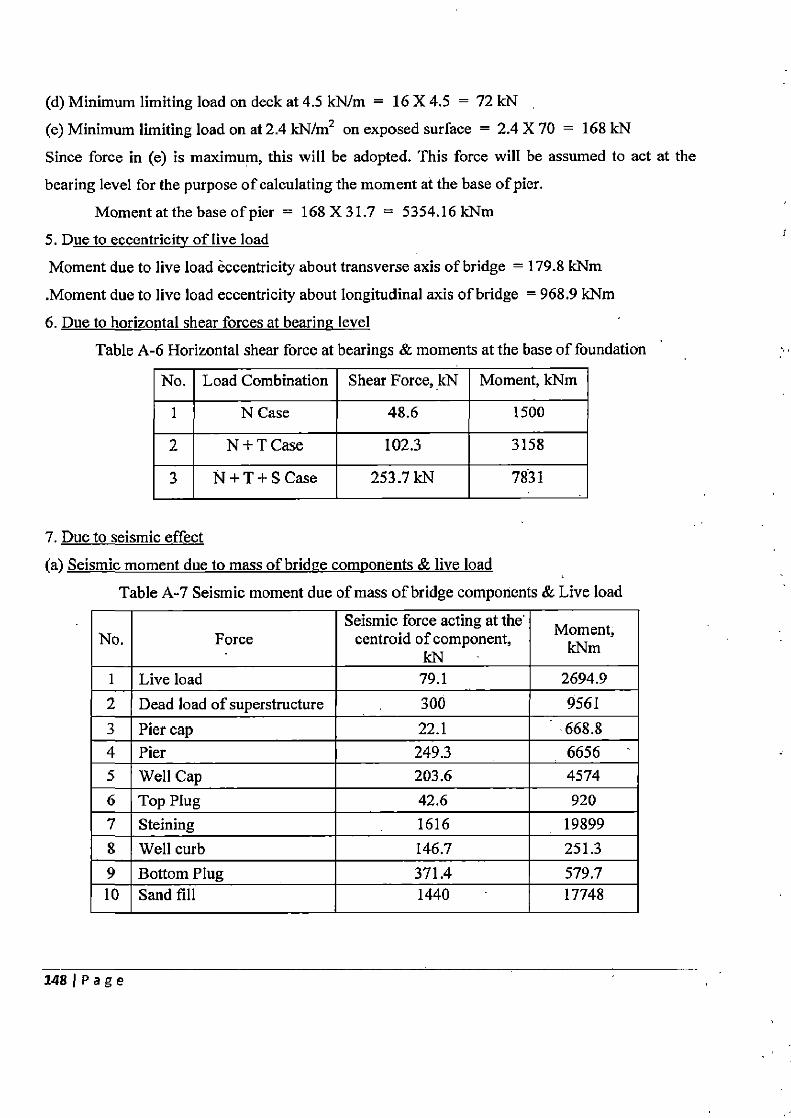
(d) Minimum limiting load on deck at 4.5 kN/m = 16 X 4.5 = 72 kN
(e) Minimum limiting load on at 2.4 kN/m2 on exposed surface = 2.4 X 70 = 168 kN
Since force in (e) is maximum, this will be adopted. This force will be assumed to act at the
bearing level for the purpose of calculating the moment at the base of pier.
Moment at the base of pier = 168X31.7 = 5354.16 kNm 5. Due to eccentricity of live load
Moment due to live load eccentricity about transverse axis of bridge = 179.8 kNm
.Moment due to live load eccentricity about longitudinal axis of bridge = 968.9 kNm
6. Due to horizontal shear forces at bearing level
Table A-6 Horizontal shear force at bearings & moments at the base of foundation
No. Load Combination Shear Force, kN Moment, kNm
1 N Case 48.6 1500
2 N+TCase 102.3 3158
3 N+T+S Case 253.7kN 7831
7. Due to seismic effect
(a) Seismic moment due to mass of bridge components & live load
Table A-7 Seismic moment due of mass of bridge components & Live load
No. Force Seismic force acting at the
centroid of component, kN
Moment, kNm
I Live load 79.1 2694.9 2 Dead load of superstructure 300 9561 3 Pier cap 22.1 668.8 4 Pier 249.3 6656 5 Well Cap 203.6 4574 6 Top Plug 42.6 920 7 Steining 1616 19899 8 Well curb 146.7 251.3 9 Bottom Plug 371.4 579.7 10 Sand fill 1440 17748
1481Page
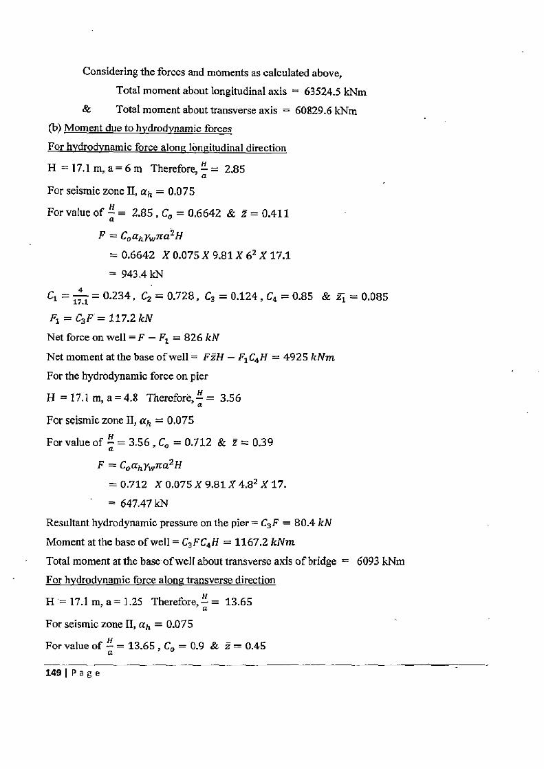
Considering the forces and moments as calculated above, Total moment about longitudinal axis = 63524.5 kNm
& Total moment about transverse axis = 60829.6 kNm (b) Moment due to hydrodynamic forces
For hydrodynamic force along longitudinal direction
H = 17.1 m, a = 6 m Therefore, `—' = 2.85 a
For seismic zone II, ah = 0.075
For value of Q= 2.85, CO = 0.6642 & z=0.411
F = CoafyWJra2H
= 0.6642 X 0.075 X 9.81 X 62 X 17.1 = 943.4 kN
C1 =j=0.234 C2 =0.728, C3 = 0.124,C4 =0.85 & 2j=0.085
FI = C3F =117.2kN Net force on well = F — Fl = 826 kN
Net moment at the base of well = FzH — F1C4H = 4925 kNm
For the hydrodynamic force on pier
H = 17.1 m, a=4.8 Therefore, " = 3.5 6
For seismic zone II, ah = 0.075
For value of Q = 3.56 , Co = 0.712 & z = 0.39
F = CoahYwrra2H
=0.712 X 0.075 X 9.81 X 4,92 X 17.
= 647.47 kN Resultant hydrodynamic pressure on the pier = C3F = 80.4 kN
Moment at the base of well = C3 FC4H = 1167.2 kNm
Total moment at the base ofwell about transverse axis of bridge = 6093 kNm For hvdrodvnamic force alone transverse direction
H = 17.1 m, a= 1.25 Therefore, !L = 13.65 a
For seismic zone II, ah = 0.075
For value of H = 13.65 , Co = 0.9 & 2 = 0.45 a
149 1 Page
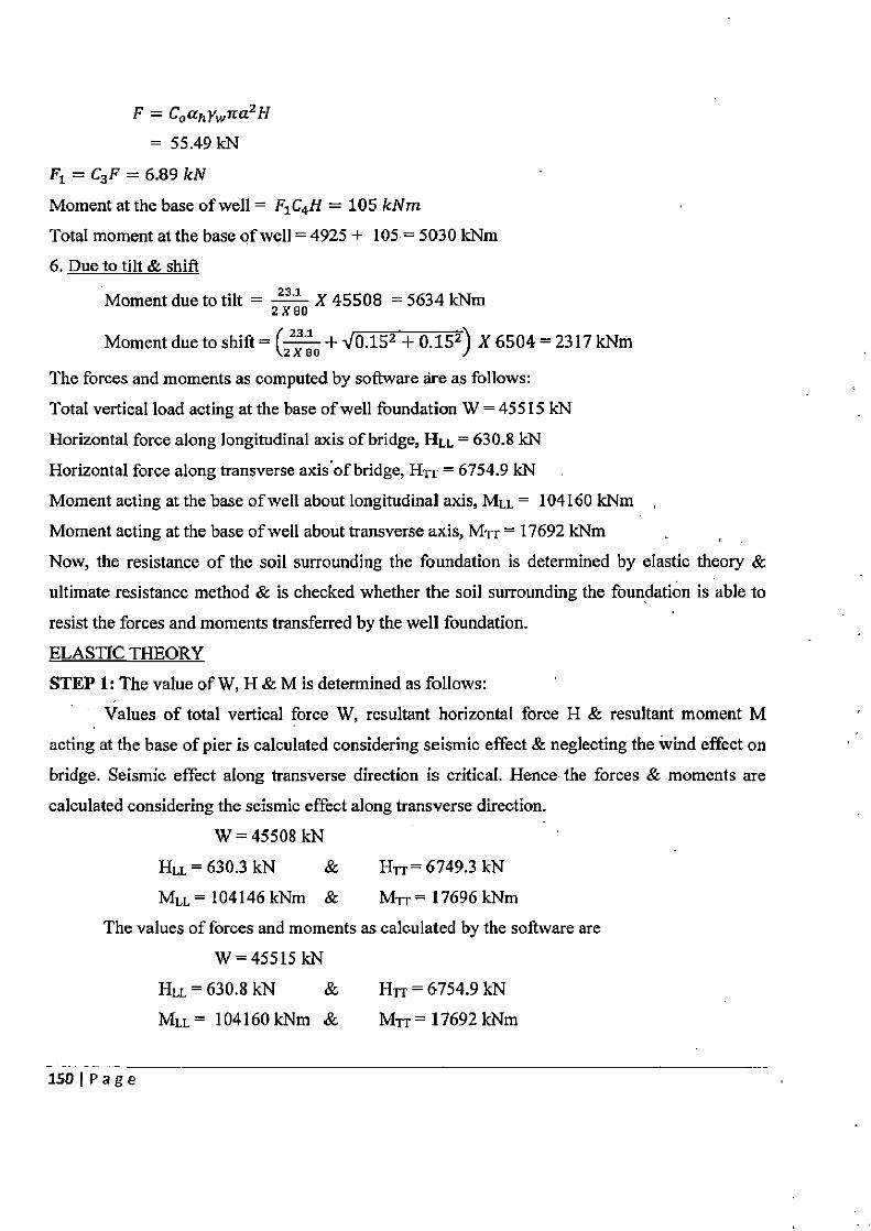
F = Coahyw7 ra2 H
= 55.49kN
F1 = C3 F = 6.89 kN
Moment at the base of well = F1C4H = 105 kNm
Total moment at the base of well = 4925 + 105• = 5030 kNm
6. Due to tilt & shift
Moment due to tilt = Z x so X 45508 = 5634 kNm
Moment due to shift = ~Z so +V0.152+ 0.152) X 6504 = 2317 kNm
The forces and moments as computed by software are as follows:
Total vertical load acting at the base of well foundation W = 45515 kN
Horizontal force along longitudinal axis of bridge, FILL = 630.8 kN
Horizontal force along transverse axis of bridge, HIT = 6754.9 kN
Moment acting at the base of well about longitudinal axis, MLL = 104160 kNm
Moment acting at the base of well about transverse axis, MTT = 17692 kNm
Now, the resistance of the soil surrounding the foundation is determined by elastic theory &
ultimate resistance method & is checked whether the soil surrounding the foundation is able to
resist the forces and moments transferred by the well foundation.
ELASTIC THEORY
STEP 1: The value of W, H & M is determined as follows:
Values of total vertical force W, resultant horizontal force H & resultant moment M acting at the base of pier is calculated considering seismic effect & neglecting the wind effect on
bridge. Seismic effect along transverse direction is critical. Hence the forces & moments are
calculated considering the seismic effect along transverse direction.
W=45508 kN
14LL = 630.3 kN & HT-r= 6749.3 kN
MLL = 104146 kNm & Myr = 17696 kNm
The values of forces and moments as calculated by the software are
W=45515 kN
HLL = 630.8 kN & H~-r = 6754.9 kN
MLL = 104160 kNm & Myr = 17692 kNm
1501 Page
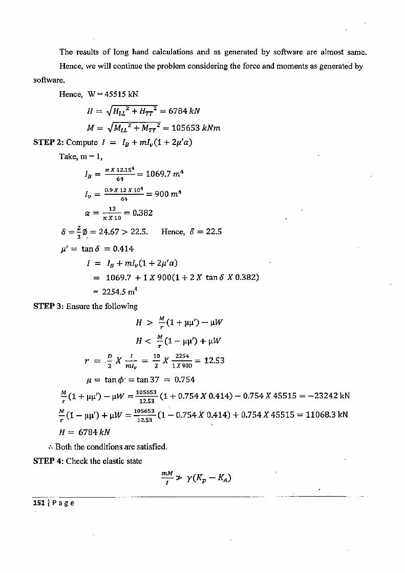
The results of long hand calculations and as generated by software are almost same.
Hence, we will continue the problem considering the force and moments as generated by
software.
Hence, W = 45515 kN
H= HLL 2 +H,2 =6784 kN
M = IMLL Z +MTT 2 =105653kNm
STEP 2: Compute I = IB + rnl„ (1 + 21i'a)
Take, m = 1, n X 15 IB =
64 = 1069.7 m4
'v = 0.9 X 12 X 104 =900m4 64
a = 12 = 0.382 trX 10
S=30= 24.67> 22.5. Hence, 8=22.5
u' = tan 6 = 0.414
I = IB +ml„(1+2µ'a)
= 1069.7 + 1 X 900(1 + 2 X tan S X 0.382)
= 2254.5 m4 STEP 3: Ensure the following
H>
H< M(1—µµ')+µW
r— o x i= 32x 2254 = 12.53 2 m!, 2 11900
p= tan ¢- =tan 37 = 0.754
M (1 + µµf) — µW = 105653 (1 + 0.754 X 0.414) — 0.754 X.45515 = —23242 kK
M (1 — µµ')+µW= 10553 (1-0.754X0.414)+0.754X45515=11068.3kM
H= 6784 kN
• Both the conditions are satisfied.
STEP 4: Check the elastic state mM
Y(Kp—Ka)
151IPage
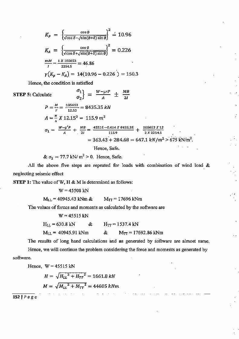
= cosp Z
KP cos S sin(0+S) sin Ø} = 10.96
_ cos 0 2
KA {toss+ sin(0+5)sin0} = 0.226
mM = 1X 105653 =46.86 1 2254.5
y(Kp — KA) = 14(10.96 — 0.226) = 150.3
Hence, the condition is satisfied
STEP 5: Calculate a1} = W A wP — zB z
p = M = 105653 = 8435.351W
r 12.53
A=X12.152 = 115.9m2 4
_ W-WP MB _ 45515 -0.414 X 8435.35 + 105653 X 12
A 21 115.9 2 X 2254.5
= 363.43+ 284.68 = 647.1 kN/»12 >675 kN/m2. Hence, Safe.
& v2 = 77.7 kN/ m2 > 0. Hence, Safe.
All the above five steps are repeated for loads with combination of wind load &
neglecting seismic effect STEP 1: The value of W, H & M is determined as follows:
W = 45508 kN
MLL = 40945.43 kNm & MTT = 17696 kNm
The values of forces and moments as calculated by the software are
W=45515 kN
HLL=630.8kN & HTT=1537.4kN
MLL = 40945.91 kNm & MT-r = 17692.86 kNm
The results of long hand calculations and as generated by software are almost same.
Hence, we will continue the problem considering the force and moments as generated by
software.
Hence, W = 45515 kN
H = VHLL2 + HTT 2 = 1661.8 kN
M = IMLL2 + M,2 = 44605 kNm
152 Page
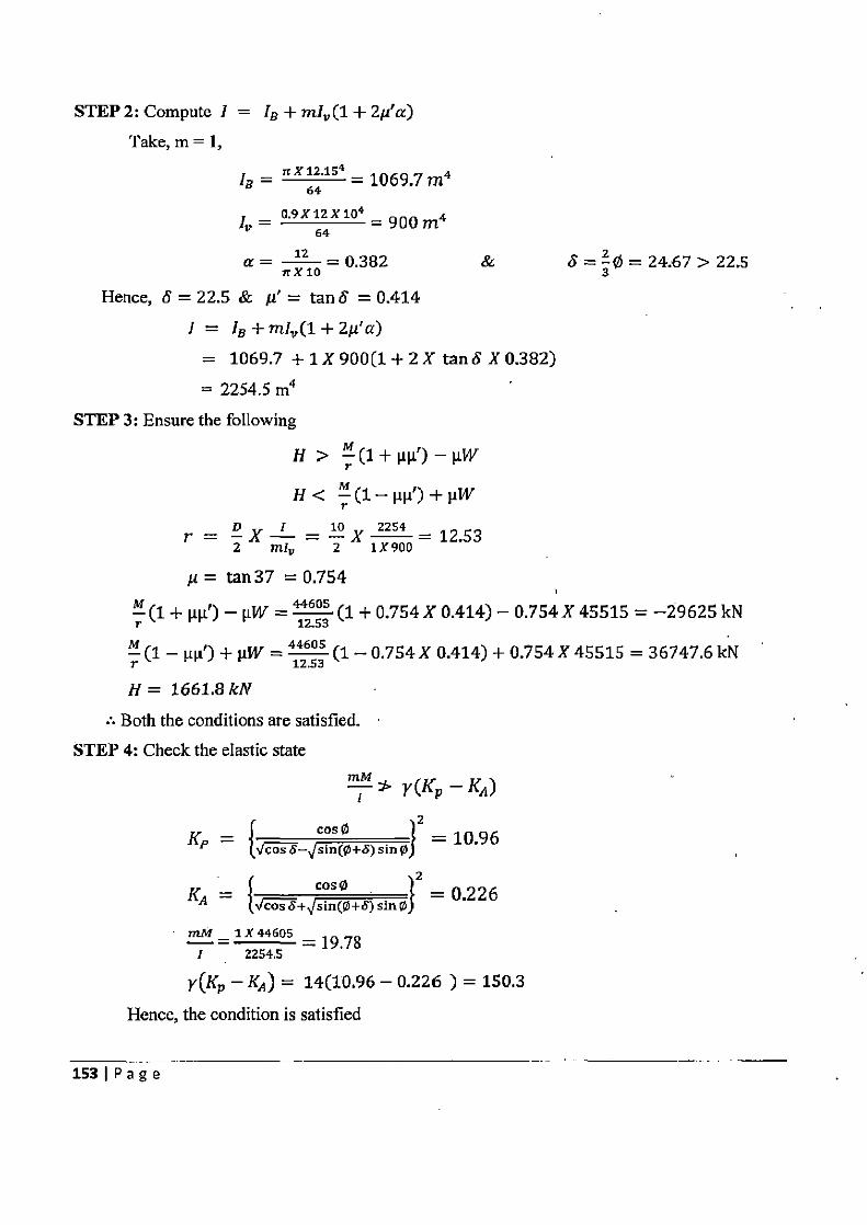
STEP 2: Compute I = IB + ml„ (1 + 2µ'a) Take, m = 1,
IB = n X 62.154 = 1069.7 rn4
I _ 0.9X12X104 =900m4 64
12 =0.382 & nX10
Hence, 6 = 22.5 & µ' = tan S = 0.414
I = IB +m/„(1+2µ'a) = 1069.7 + 1 X 900 (1 + 2 X tan 6 X 0.382)
= 2254.5 m4
STEP 3: Ensure the following
H>
H< r
r = X r = E x 2254 =12.53
2 m1„ 2 1X900
u= tan 37 = 0.754
S=3¢= 24.67>22.5
M(1+ µp') —µW =412653 (1+0.754 X 0.414)-0.754 X 45515=-29625kN
M (1 — 1LFl) + i.tW = 44605 (1— 0.754 X 0.414) + 0.754 X 45515 = 36747.6 kN T 12.53
H= 1661.8 kN
• Both the conditions are satisfied. STEP 4: Check the elastic state
MM y(Kp — K4)
_ cos 0 2 KP — { cos6— sin(0+5)sin0) = 10.96
_ cos 4 2
KA cosh+ sin(0+8)sin0} = 0.226
mM -1X44605 — = 19.78
1 2254.5
y(K p — KA) = 14(10.96 — 0.226) = 150.3
Hence, the condition is satisfied
153IPage
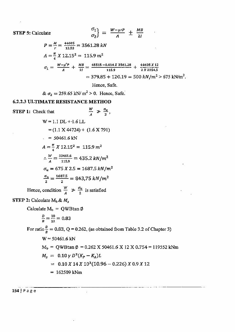
STEP 5: Calculate 01) = W—µ'P + n~a Q2 A 21
M 44605 P = r = 12.53 = 3561.28 kN
A=. X12.152 = 115.9m2 4
_ W-µ'P + MB - 45515 -0.414X 3561.28 + 44605 X 12
A 21 115.9 2X2254.5
= 379.85 + 120.19 = 500 kN/m2 > 675 kN/m2. Hence, Safe.
& 62 = 259.65 kN/ m2 > 0. Hence, Safe. 6.2.2.3 ULTIMATE RESISTANCE METHOD
STEP 1: Check that A 2 1:5=97~~i011
=(1.1X44724)+ (1.6X791)
A=X12.152 = 115.9 m2 4 W _ 50461.6
= 435.2 kN/m2 A 115.9
c„ = 675 X 2.5 = 1687.5 kN/m2 Qu _ 1687.5
= 843,75 kN/m2 2 — 2
Hence, conditionA Z is satisfied
STEP 2: Calculate Mb & MM Calculate Mb = QWBtan O
0-10=0.83
For ratio B = 0.83, Q = 0.262, (as obtained from Table 3.2 of Chapter 3)
W = 50461.6 kN Mb = QWBtan 0 = 0.262 X 50461.6 X 12 X 0.754 = 119552 kNm
Ms = 0.10yD3(KP —KA )L
= 0.10X14X103(10.96-0.226)X0.9X12
= 162509 kNm
154 j P a g e
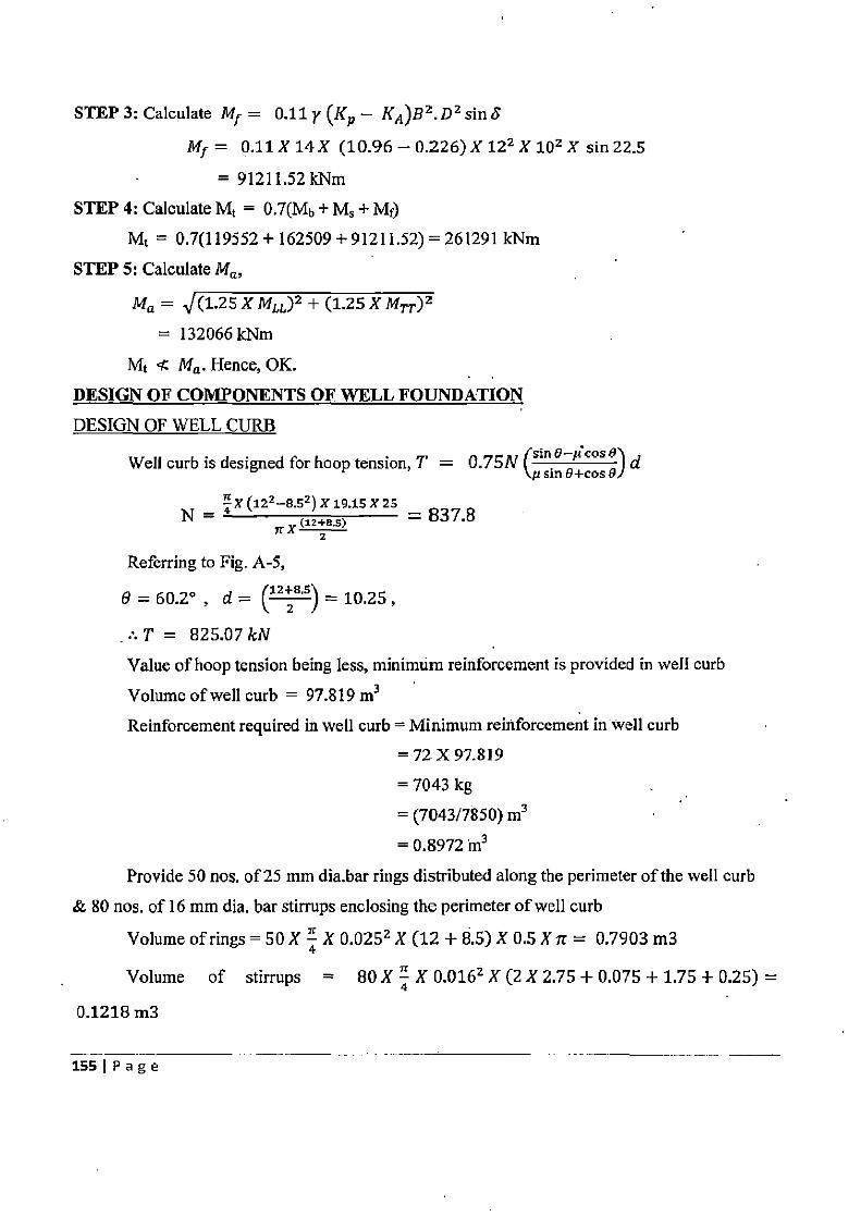
STEP 3: Calculate Mf = 0.11 y (Kp — K A)B2. D2 sin S
Mf = 0.11 X 14 X (10.96 — 0.226) X 122 X 101 X sin 22.5
= 91211.52 kNm STEP 4: Calculate Mt = 0.7(Mb + Ms + Mf)
Mt = 0.7(119552 + 162509 + 91211.52) = 261291 kNm
STEP 5: Calculate Ma,
Ma = (1.25XMLL)2 +(1.25XMTT )2
= 132066 kNm
Mt Ma. Hence, OK.
DESIGN OF COMPONENTS OF WELL FOUNDATION
DESIGN OF WELL CURB
Well curb is designed for hoop tension, T = 0.75N (sin a—µcos 0) d `p sin o+cos of
Ex (122_o.52) 19.15X29 N = X (12+8.5) = 837.8
z
Referring to Fig. A-5,
B=60.2°, d (12+8.51_10.25,
= 825.07 kN J
Value of hoop tension being less, minimum reinforcement is provided in well curb
Volume of well curb = 97.819 m3 Reinforcement required in well curb = Minimum reinforcement in well curb
=72X97.819
= 7043 kg
= (7043/7850) m3
= 0.8972 'm3
Provide 50 nos. of 25 mm dia.bar rings distributed along the perimeter of the well curb
& 80 nos. of 16 mm dia. bar stirrups enclosing the perimeter of well curb
Volume of rings = 50 X 4 X 0.0252 X (12 + 8.5) X 0.5 X it = 0.7903 m3
Volume of stirrups = BO X 4 X 0.0167 X (2 X 2.75 + 0.075 + 1.75 + 0.25) _
0.1218 m3
1551 Page
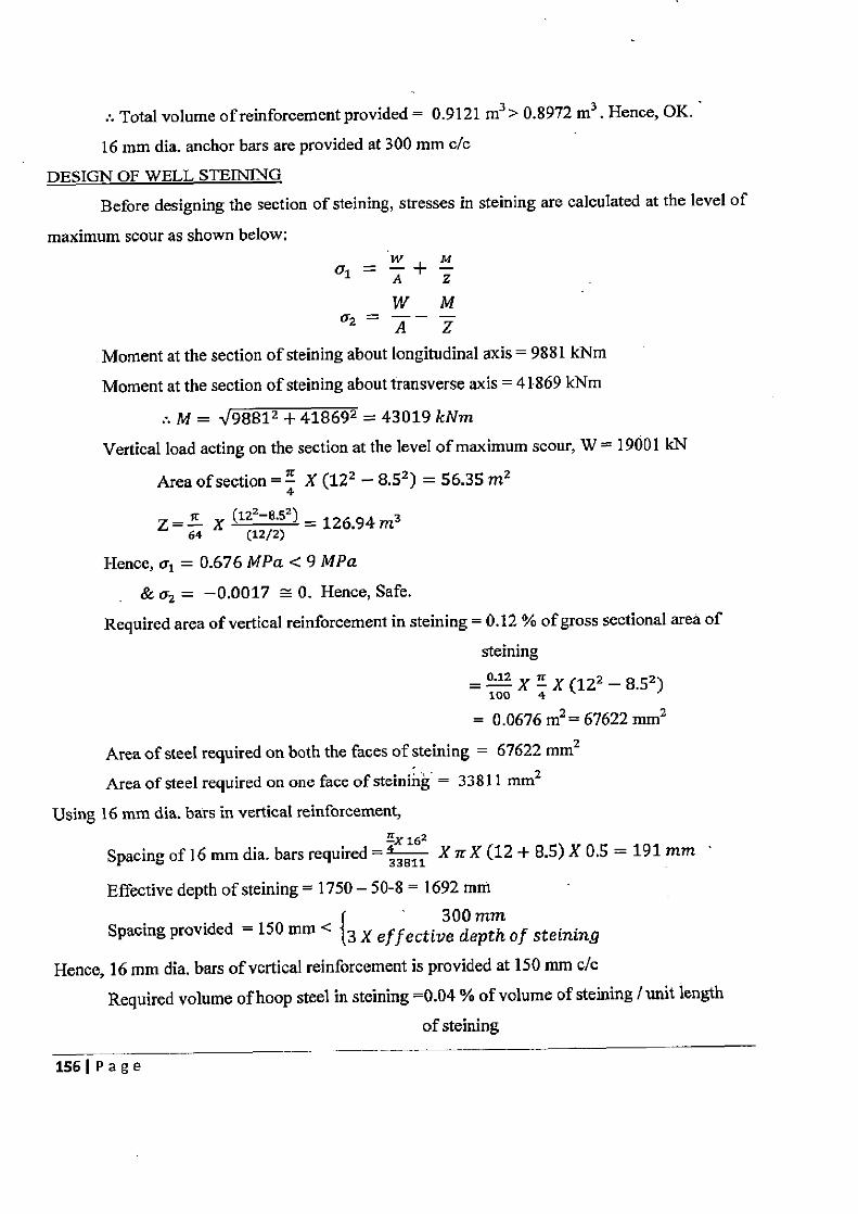
:. Total volume of reinforcement provided = 0.9121 m3 > 0.8972 m3 . Hence, OK.
16 mm dia. anchor bars are provided at 300 mm c/c
DESIGN OF WELL STEWING
Before designing the section of steining, stresses in steining are calculated at the level of
maximum scour as shown below:
1 A Z
W M
Moment at the section of steining about longitudinal axis = 9881 kNm
Moment at the section of steining about transverse axis = 41869 kNm
M = J 98812 + 418692 = 43019 kNm
Vertical load acting on the section at the level of maximum scour, W = 19001 kN
Area of section = 4 X (122 — 8.52) = 56.35 m2
Z = " X (122_852) = 126.94m3 64 (12/2)
Hence, a1 = 0.676 MPa < 9 MPa
& a2 = —0.0017 - 0. Hence, Safe. Required area of vertical reinforcement in steining = 0.12 % of gross sectional area of
steining
_ 0.12 X 4 X (122 — 8.52)
= 0.0676 m2 = 67622 mm2
Area of steel required on both the faces of steining = 67622 mm2
Area of steel required on one face of steining = 33811 mm2
Using 16 mm dia. bars in vertical reinforcement, EX 162
Spacing of 16 mm dia. bars required = 33g 811 X it X (12 + 8.5) X 0.5 = 191 mm
Effective depth of steining = 1750 — 50-8 = 1692 mm 300 mm
Spacing provided = 150 mm < {3 X effective depth of steining
Hence, 16 mm dia. bars of vertical reinforcement is provided at 150 mm c/c Required volume of hoop steel in staining =0.04 % of volume of steining / unit length
of staining
156IPage
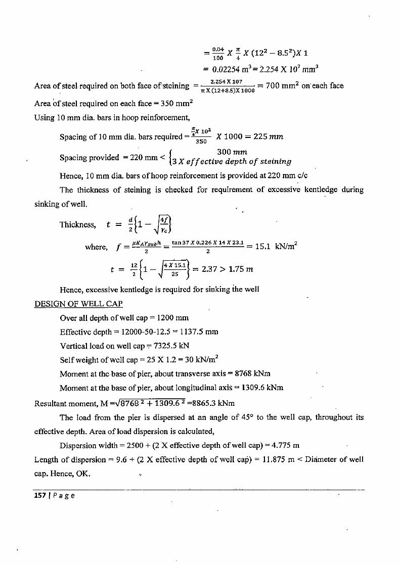
100 X 4 X (122 — 8.52)X 1
= 0.02254 m3 = 2.254 X 107 mm3
Area of steel required on both face of'steining = z•zs4x 107 = 700 mmz on'eaeh face u x (12+8.$)x 1000
Area of steel required on each face = 350 mm2
Using 10 mm dia. bars in hoop reinforcement, 102
Spacing of 10 mm dia. bars required = 43so X 1000 = 225 mm
Spacing provided = 220 mm < 300 mth
3 X e f f ective depth of steining
Hence, 10 mm dia. bars of hoop reinforcement is provided at 220 mm c/c
The thickness of steining is checked for requirement of excessive kentledge during
sinking of well.
Thickness, t = flu. — f
where, f = ILKA Zsubh = tan 37 X 0.2 2 X 14 X 23.1 = 15.1 kN/m2
t = z [1_ 4 255'1 } = 2.37 > 1.75 m
Hence, excessive kentledge is required for sinking the well
DESIGN OF WELL CAP
Over all depth of well cap = 1200 mm
Effective depth = 12000-50-12.5 = 1137.5 mm
Vertical load on well cap = 7325.5 RN
Self weight of well cap = 25 X 1.2 = 30 kN/m2
Moment at the base of pier, about transverse axis = 8768 kNm
Moment at the base of pier, about longitudinal axis = 1309.6 kNm
Resultant moment, M =V8768 2 + 1309.6 2 =8865.3 kNm
The load from the pier is dispersed at an angle of 45° to the well cap, throughout its
effective depth. Area of load dispersion is calculated,
Dispersion width = 2500 + (2 X effective depth of well cap) = 4.775 m
Length of dispersion = 9.6 + (2 X effective depth of well cap) = 11.875 m < Diameter of well
cap. Hence, OK. ,-
157 Page
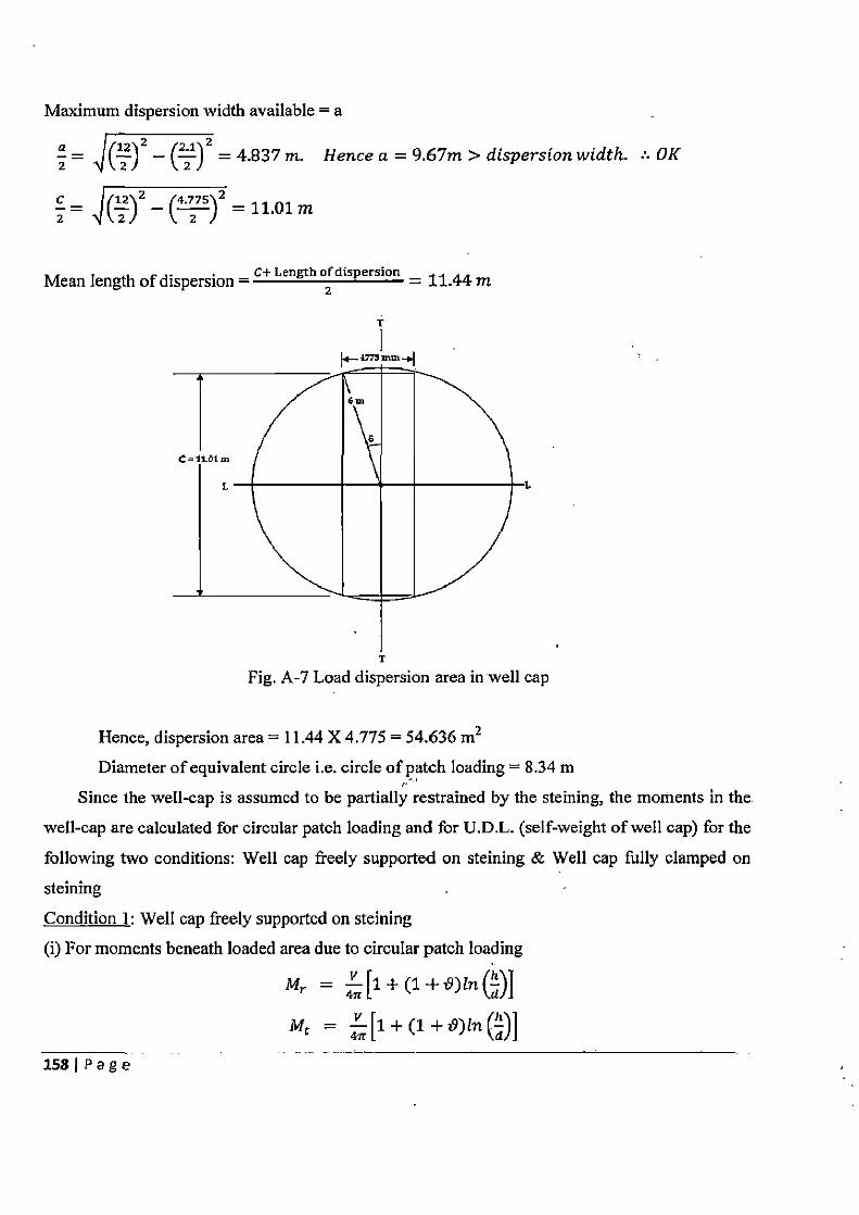
Maximum dispersion width available = a
a = Z)Z — (al)2 = 4.837m. Hence a = 9.67m > dispersion width. :. OK
z — ~()Z—~4zs\z=11.01m
Mean length of dispersion = C+ Length 2 dispersion = 11.44 m
T
Fig. A-7 Load dispersion area in well cap
Hence, dispersion area = 11.44 X 4.775 = 54.636 m2
Diameter of equivalent circle i.e. circle of patch loading = 8.34 m Since the well-cap is assumed to be partially restrained by the steining, the moments in the
well-cap are calculated for circular patch loading and for U.D.L. (self-weight of well cap) for the
following two conditions: Well cap freely supported on steining & Well cap fully clamped on steining -
Condition 1: Well cap freely supported on steining (i) For moments beneath loaded area due to circular patch loading
Mr — 4ff
[1
Mr 4a [1
1581 Page
Hence, Mr = Mt = ' 4rz'S [l + (1 + 0.18)In (814~~ = 833.1 kNm
(ii) For moments beneath unloaded area due to circular patch loading
Mr — 4K (1+t9)ln(l)
Mt —
Atsupport,d=h;l=d =1
Hence, Mr = 0 & Mt = _ 7324,5 [(1-0.18)— (1 + 0.18)In(1)] = 477.95 kNm
The radial and tangential moments in the well cap due to U.D.L. are given by
Mr = 64Z
Mt = 64-[(3 +19) -- (1 +.3i9)e]
d At centre, d = 0; = = 0 h
Mr = Mt = 30 64 22 (3 + 0.18) = 214.7 kNm
At support, d = d = 1 h; i = h
Mr = 0 Mt = 30 X 22 [(3 + 0.18) — (1 + 3XO.18)X1] = 110.7 kNm
Condition 2: Well cap fully clamped at support (i) For moments beneath loaded area due to circular patch loading
Mr 4rrL(1+ ~9)ln la/J
Mt
12 Mr = Mt =
7324.5[(1 + 0.18)ln ( 34)] = 250.2 kNm
(ii) For moments beneath unloaded area due to circular patch loading,
Mr — z
Mt = a 1(_) '9(1 — i9) — (1 + 6)1n() — i9
d At support, d = h; i; = = 1 h
1591 Page
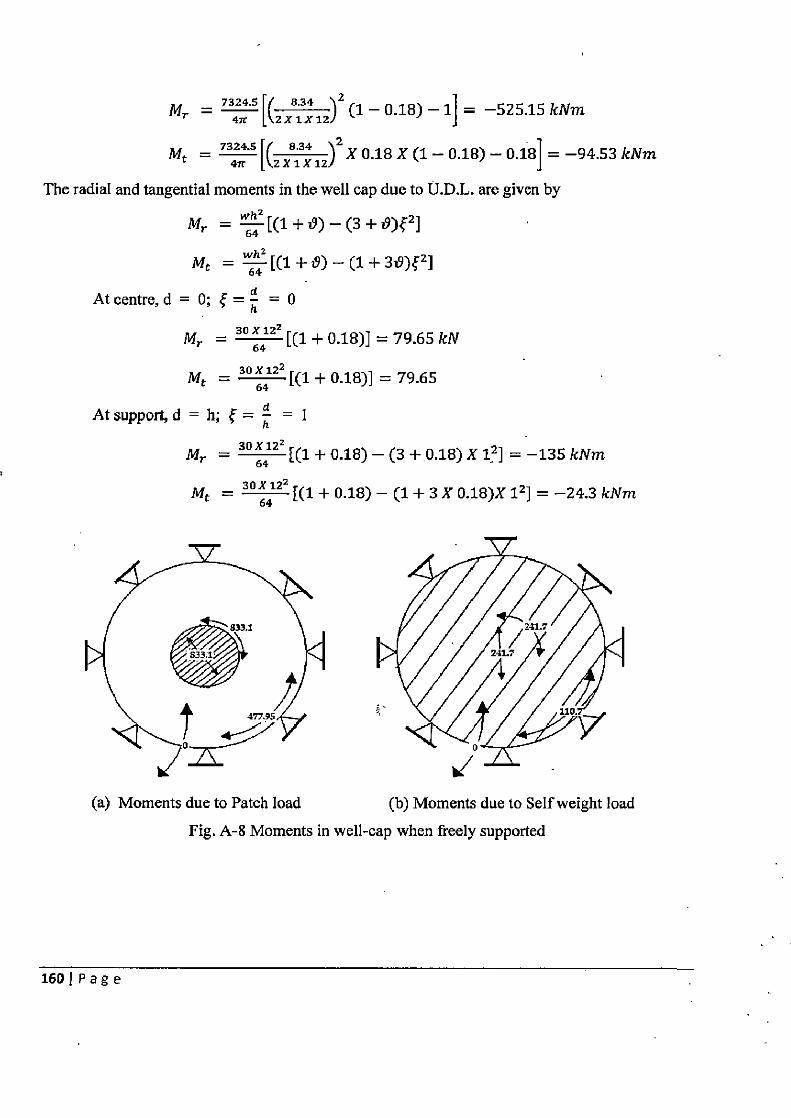
7324.5 r 8.34 12 MT — 47t [`zx1xlzl (1 — 0.18) —1] = —525.15 kNm
7324.5 8.34 2 Mt = 47r R2 x 1 12) X 0.18 X (1— 0.18) — 0.18] = —94.53 kNm
The radial and tangential moments in the well cap due to U.D.L. are given by
Mr = 642 [(1+D) — (3 +fl)e2 ]
Mt =
At centre, d = 0; j = h = 0
30X122 Mr = [(1 + 0.18)] = 79.65 kN 64 Mt = 30k'1 22 [(1 + 0.18)] = 79.65
At support, d = h; 4= d = I h 30 X 122 Mr = 64 [(1 + 0.18) — (3 +0.18) X 12] = —135 kNm
Mt = 30X6122 [(1 + 0.18) — (1 + 3 X 0.18)X 12 ) = —24.3 kNm
Si 1
V
(a) Moments due to Patch load (b) Moments due to Self weight load
Fig. A-8 Moments in well-cap when freely supported
160 Page
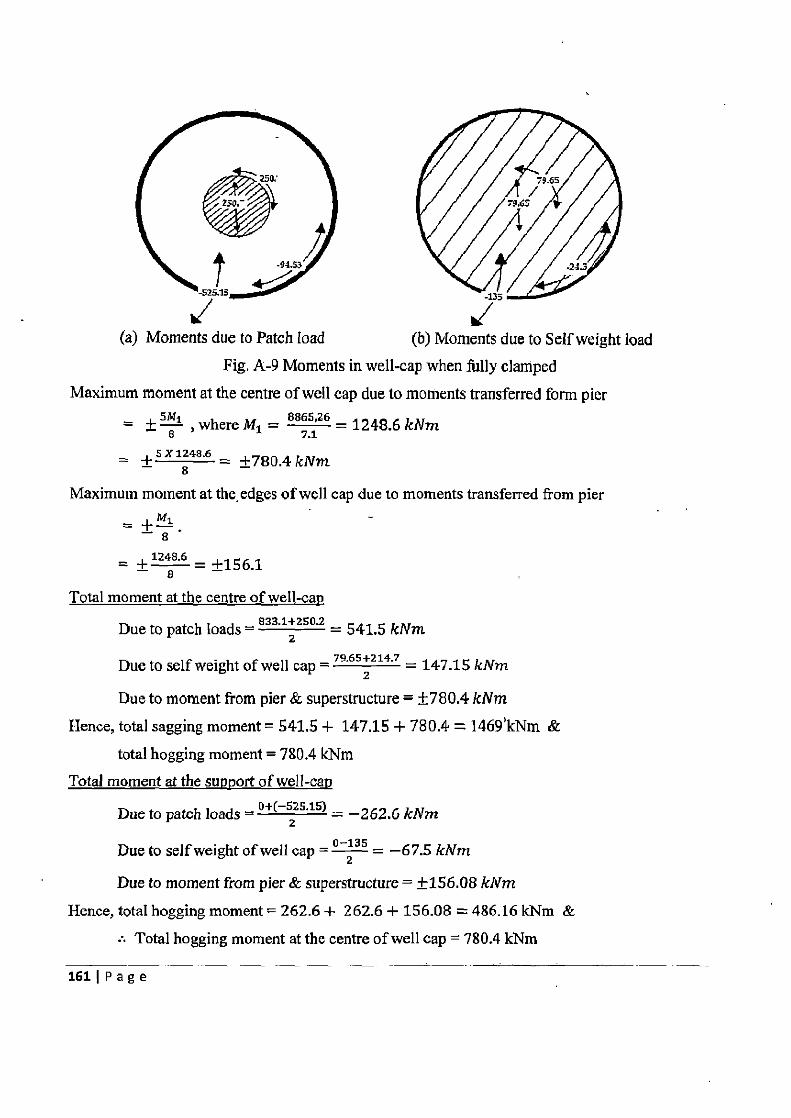
Fl 1Z T
(a) Moments due to Patch load I
(b) Moments due to Self weight load Fig. A-9 Moments in well-cap when fully clamped
Maximum moment at the centre of well cap due to moments transferred form pier
=± 5 81 ,where M1 = 8865,26 = 1248.6 kNm
+5'1248.6 ±780.4 kNm
Maximum moment at the. edges of well cap due to moments transferred from pier - r
- 9 1248.6 _ ± e = ±156.1
Total moment at the centre of well-cap
Due to patch loads = 833.1
2+250.2 = 541.5 kNm
Due to self weight of well cap = 79.65+1Z" = 147.15 kNm
Due to moment from pier & superstructure = ±780.4 kNm Hence, total sagging moment = 541.5 + 147.15 + 780.4 = 1469'kNm &
total hogging moment = 780.4 kNm Total moment at the support of well-cap
Due to patch loads = o+(— Zzs.15) = —262.6 kNm
Due to self weight of well cap ='_"s = —67.5 kNm 2
Due to moment from pier & superstructure = ±156.08 kNm Hence, total hogging moment = 262.6 + 262.6 + 156.08 = 486.16 kNm &
• Total hogging moment at the centre of well cap = 780.4 kNm
1611Page
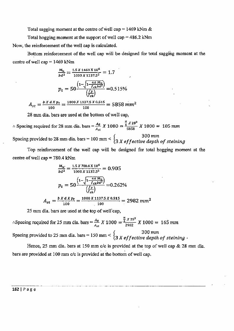
Total sagging moment at the centre of well cap = 1469 kNm & Total hogging moment at the support of well cap = 486.2 kNm
Now, the reinforcement of the well cap is calculated. Bottom reinforcement of the well cap will be designed for total sagging moment at the
centre of well cap = 1469 kNm MM _ 1.5 X 1469 X 106
=13 bdz 1000X1137.52
r _ 4.6 Mu
Pt = 5011 of f =0.515% v ckI
A =
bXdXpt _ 1000 X 1137.5 X 0.515=5$58 T]7.,rriz
St 100 100
28 mm dia. bars are used at the bottom of well cap,
Spacing required for 28 mm dia. bars = Ae X 1000 = 45858 X 1000 = 105 mm
Spacing provided to 28 mm dia. bars = 100 mm < 300 mm k X e f f ective depth of steining
Top reinforcement of the well cap will be designed for total hogging moment at the
centre of well cap = 780.4 kNm Mu. _ 1.5 X 780.4 X 106 = 0.905 bd? 1000X1137.52
f — 4.6 Mu 1 f— c Pt = 50 fy =0.262%
~cki A =
b X d X pr = 1000 X 1137.5 X 0.515 = 2982 mm2 sr 100 100
25 mm dia. bars are used at the top of well'cap, rz 2
.Spacing required for 25 mm dia. bars = A° X 1000 = `2982 X 1000 = 165 mm
Spacing provided to 25 mm dia. bars = 150 mm < 300 mm {3 X e f f ective depth of steining
Hence, 25 mm dia. bars at 150 mm c/c is provided at the top of well cap & 28 mm dia.
bars are provided at 100 mm c/c is provided at the bottom of well cap.
162 I P a g e
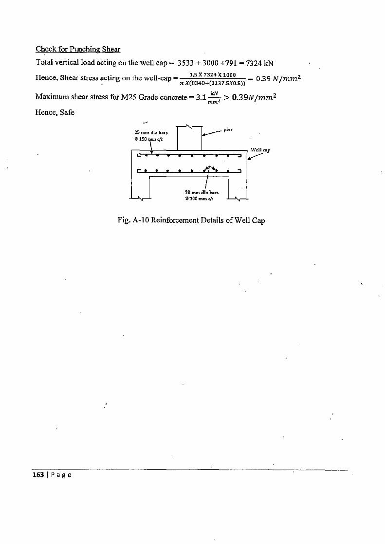
Check for Punching Shear
Total vertical load acting on the well cap = 3533 + 3000 +791 = 7324 kN X Hence, Shear stress acting on the well-cap = is
X(83 4 7324 X 1000
0+(1137.5X0.5)) _ 0.39 N/mm2 n
Maximum shear stress for M25 Grade concrete = 3.1- > 0.39N/mm2 Hence, Safe
25 dia bars I v pier
z 1500 nmi c/c
Wea cap
26 . dia ban
Fig. A-10 Reinforcement Details of Well Cap
163 1 P a g e
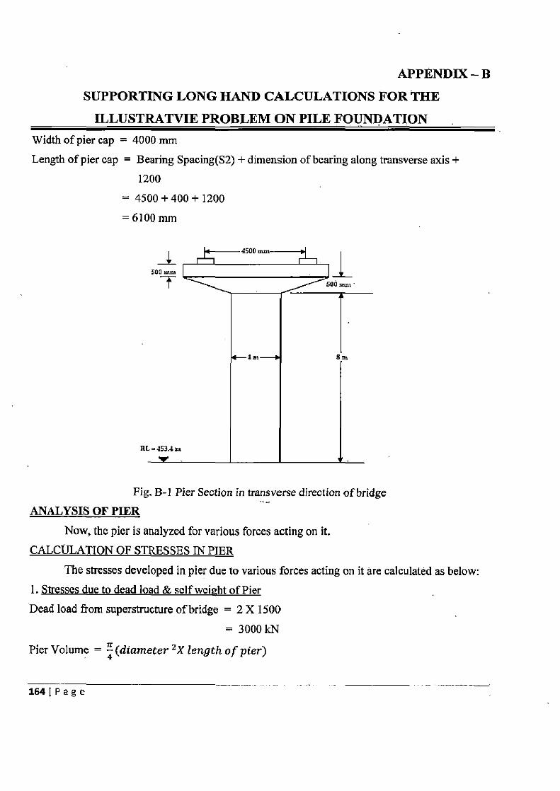
APPENDIX — B
SUPPORTING LONG HAND CALCULATIONS FOR THE ILLUSTRATVIE PROBLEM ON PILE FOUNDATION
Width of pier cap = 4000 mm Length of pier cap = Bearing Spacing(S2) + dimension of bearing along transverse axis +
1200 = 4500+400+ 1200
=6100mm
R[
Fig. B-I Pier Section in transverse direction of bridge ANALYSIS OF PIER
Now, the pier is analyzed for various forces acting on it. CALCULATION OF STRESSES IN PIER
The stresses developed in pier due to various forces acting on it are calculated as below: 1. Stresses due to dead load & self weight of Pier Dead load from superstructure of bridge = 2 X 1500
111 .1I
Pier Volume = 4 (diameter ZX length of pier)
1641Page
4(4X8)
= 100.53 m3
Volume of tapered portion of Pier cap = (6'1 x 42+(4 x 4~ X 0.5 = 10.1 m3
Volume of rectangular portion of Pier cap = 12.2 m3 Total volume of pier & pier cap = 122.83 m3 Hence, total weight of pier & pier cap = 122.83 X 25 = 3070.8 kN
C/s area of pier = 12.57 m2
Stresses due to dead load of superstructure & weight of pier & pier cap = 3070.8 +3000 12.57
= 483.1 kN/m2 2. Stresses due to_eccentricity of live load
Moment of Inertia about X axis i.e. T-T axis of bridge, = Moment of Inertia about Y axis i.e. L-L axis of bridge, I},~,
=x44=12.57 m4 64
(a) Due to eccentric live load about transverse axis of bridge Vertical live load on pier, producing maximum stress about transverse axis = 385 kN, & Moment due to live load eccentricity about transverse axis of bridge, producing maximum stress about transverse axis = 192.5 kNm
Stress at the base of pier due to eccentricity of live load about transverse axis
A 1xx
385 + /192.5 .X2 1 12.57 - 1\12.57
= 61.27 kN/m2 or 0 kN/m2
(b) Due to eccentric live load about longitudinal axis of bridge
Vertical live load on pier, producing maximum stress due about longitudinal axis = 397.5 kN, & Moment due to live load eccentricity about transverse axis of bridge, producing maximum
stress about longitudinal axis = 377.6 kNm Stress at the base of pier due to eccentricity of live load about longitudinal axis
_ ?+ MVy x A — I yy
1651Page
397.5 + (377.6 X z) 12.57 12.57
= 91.73 kN/ma or -28.47 kN/m2
NOTE: The stresses acting at the base of pier due to live load eccentricity is calculated on
program made in Microsoft Excel Worksheet.
3. Stresses due to longitudinal forces (a) Due to tractive effort or braking forces orces
Braking effect is invariably greater than tractive effort. Hence, braking effort is considered.
Longitudinal force of Class AA load = 0.2 X 400 :1 L
Moment at the base = 80 X 12.5
= 1000 kNm
Stress at the base of pier due to braking effort = -I- M y
_ +1000 X2 - 12.57
_ ±159.16 kN/m2
(b) Due to resistance at hearings
Coefficient of friction on the left side of bearing = 0.05 Coefficient of friction on the right side of bearing (reducing 5%) = 0.0475
Assume the combination of dead load & live load acting on the left side bearing and dead load
on right side bearing
Maximum live load reaction acting on the left side bearing = 385 kN
(as calculated on program prepared in Microsoft Excel Worksheet)
Total resistance to sliding on the left side bearing = 0.05 X (1500 + 385) = 94.25 kN &
Total reacting on the right side bearing = 0.0475 X 1500 = 71.25 kN
:• Unbalanced force = 23 kN
Moment due to unbalanced force at the base of pier = 23 X 9.3 = 213.9 kNm
:• Stress at the base of pier = ± MXX y = -F 21 s X 2 = ±34.04 kN/m2
—5.43 kN/m2
4. Stresses due to wind load
(a) Area of superstructure as seen in elevation = 70 m2
166IPage
The height of exposed surface of bridge structure = 10.3 m
For 10.3 m, the intensity of wind load is taken as 0.92 kN/ m2
Hence, Total wind force = 70 X 0.92 = 64.37 kN/ m2
(b) Considering the wind load acting on moving live load having magnitude of 3 kN/m & acting at 1.5 m above road way,
Wind force against the moving load = 1.2 X 3 = 4.2 kN (c) Total wind force as in (a) & (b) above = 68.57 kN
(d) Minimum limiting load on deck at 4.5 kN/m = 1.2 X 4.5 = 5.4 kN (e) Minimum limiting load on at 2.4 kN/m2 on exposed surface = 2.4 X 70 = 168 kN
Since force in (e) is maximum, this will be adopted. This force will be assumed to act at the
bearing level for the purpose of calculating the moment at the base of pier.
Moment at the base of pier = 168 X 10.3 = 1730.4 kNm
Stress at the base of pier = ± rr
+ 1730.4 X2 12.57
_ ±275.4 kN/m2
5. Stresses due to seismic effect (a) Seismic moment acting at the base of pier due to the masses of bridge component & live load
Lever arm of tapered portion of pier cap from the base of pier = 8 + r (6.1 X 4)X 0.5+01 [(6.1 X 4)+(4 X 4)1
=8.3m
Hence, total seismic moment due to mass of bridge components & live load about longitudinal
axis = ((397.5 X 12.5) + (305 X 8.75) + (252.5 X 8.3) + (252.5 X 8.3) + (2513 X
4) + (1500 X 10.3.X 2)) X 0.1
= 5068.7 kNm
Total seismic moment due to mass of bridge components & live load about transverse axis =((305X 8.75) + (252.5 X 8.3)+(252.5 X 8.3) + (2513 X4)+(1500 X 10.3 X 2)) X 0.1
= 4571.8 kNm
Resultant stress due to seismic effect about transverse axis = ± Lxx y fxx
_ + (4571.8)X2 - 12.57
±727.6 kN /m2
167 I P a g e
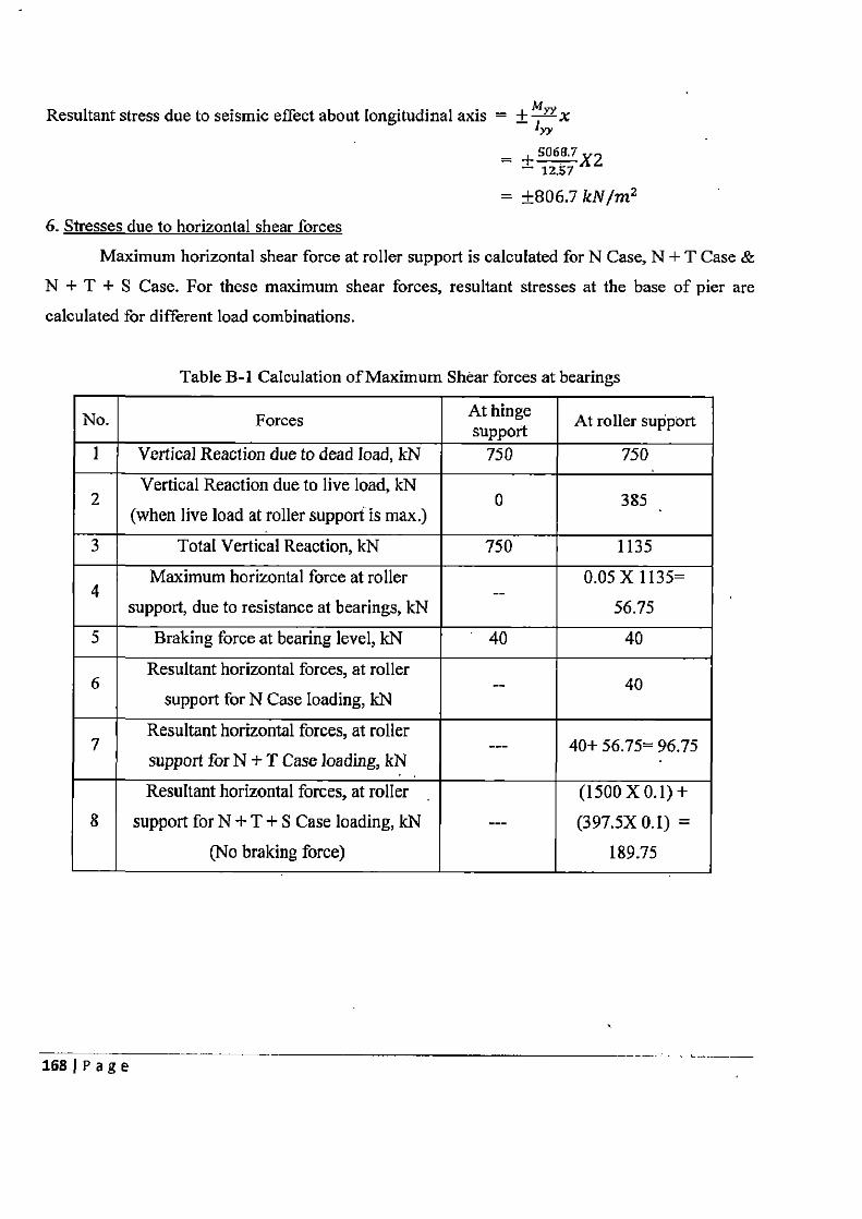
Resultant stress due to seismic effect about longitudinal axis = ± M!-v x ry
_ + so"'7X2 12.57
= ±806.7 kN/m2 6. Stresses due to horizontal shear forces
Maximum horizontal shear force at roller support is calculated for N Case, N + T Case & N + T + S Case. For these maximum shear forces, resultant stresses at the base of pier are
calculated for different load combinations.
Table B-1 Calculation of Maximum Shear forces at bearings
No. Forces At hinge At roller support support I Vertical Reaction due to dead load, kN 750 750
Vertical Reaction due to live load, kN 2 0 385
(when live load at roller support is max.)
3 Total Vertical Reaction, kN 750 1135
Maximum horizontal force at roller 0.05 X 1135= 4 --
support, due to resistance at bearings, kN 56.75
5 Braking force at bearing level, kN 40 40
Resultant horizontal forces, at roller 6 -- 40
support for N Case loading, kN
Resultant horizontal forces, at roller 7 --- 40+ 56.75= 96.75
support for N + T Case loading, kN
Resultant horizontal forces, at roller (1500 X 0.1) + 8 support for N + T + S Case loading, kN --- (397.5X 0.1) _
(No braking force) 189.75
158IPage
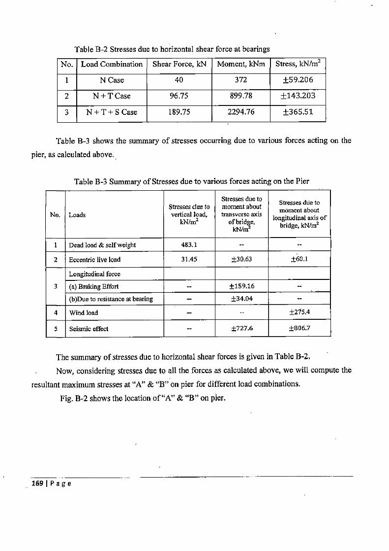
Table B-2 Stresses due to horizontal shear force at bearings
No. Load Combination Shear Force, kN Moment, kNm Stress, kN/m2
1 N Case 40 372 ±59.206
2 N + T Case 96.75 899.78 ±143.203
3 N + T + S Case 189.75 2294.76 ±365.51
Table B-3 shows the summary of stresses occurring due to various forces acting on the
pier, as calculated above.
Table B-3 Summary of Stresses due to various forces acting on the Pier
Stresses due to Stresses due to Stresses due to moment about moment about No. Loads vertical load,
kN/m2 transverse axis longitudinal axis of of bridge, bridge, kN/m kN/m2
1 Dead load & self weight 483.1 --
2 Eccentric live load 31.45 ±30.63 ±60.1
Longitudinal force 3 (a) Braking Effort -- ±159.16 --
(b)Due to resistance at bearing -- ±34.04 --
4 Wind load -- -- ±275.4
5 Seismic effect -- ±727.6 ±806.7
The summary of stresses due to horizontal shear forces is given in Table B-2.
Now, considering stresses due to all the forces as calculated above, we will compute the
resultant maximum stresses at "A" & `B" on pier for different load combinations.
Fig. B-2 shows the location of "A" & `B" on pier.
169 I P a g e
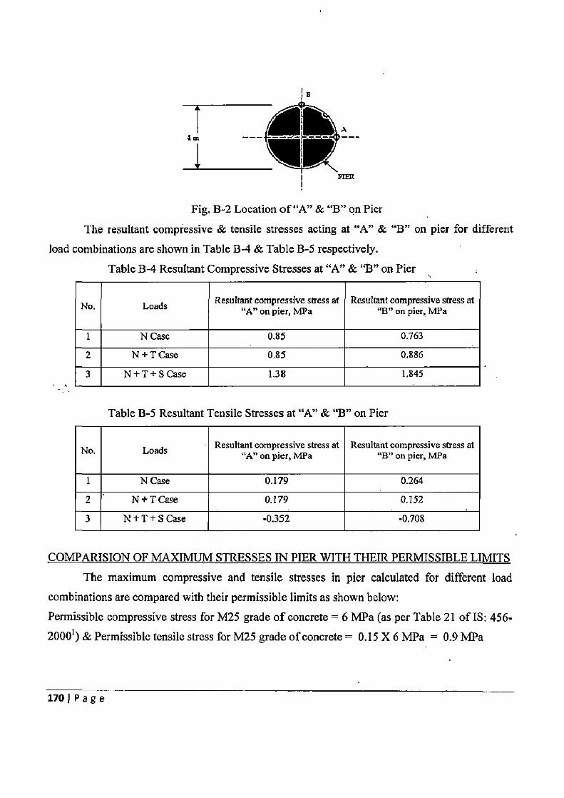
Fig. B-2 Location of "A" & "B" on Pier
The resultant compressive & tensile stresses acting at "A" & "B" on pier for different
load combinations are shown in Table B-4 & Table B-5 respectively.
Table B-4 Resultant Compressive Stresses at "A" & "B" on Pier
No. Loads Resultant compressive stress at " A" on pier, MPa
Resultant compressive stress at "B" on pier, MPa
1 N Case 0.85 0.763
2 N+TCase 0.85 0.886
3 N+T+S Case 1.38 1.845
Table B-5 Resultant Tensile Stresses at "A" & "B" on Pier
No. Loads Resultant compressive stress at "A" on pier, MPa
Resultant compressive stress at "B" on pier, MPa
1 N Case 0.179 0.264
2 N+TCase 0.179 0.152
3 N + T + S Case -0.352 -0.708
COMPARISION OF MAXIMUM STRESSES IN PIER WITH THEIR PERMISSIBLE LIMITS
The maximum compressive and tensile stresses in pier calculated for different load combinations are compared with their permissible limits as shown below:
Permissible compressive stress for M25 grade of concrete = 6 MPa (as per Table 21 of IS: 456-20001) & Permissible tensile stress for M25 grade of concrete = 0.15 X 6 MPa = 0.9 MPa
170 1 Page
• Maximum compressive stress under "N" Case loading = 0.85 MPa < 6 MPa. Hence, Safe.
• Maximum compressive stress under "N + T" Case loading = 0.886 MPa < 6.9 MPa (15%
increase). Hence, Safe.
• Maximum compressive stress under "N + T + S" Case loading = 1.845 MPa < 9 MPa
(50% increase). Hence, Safe.
• Maximum tensile stress under "N + T + S" Case loading = 0.708 MPa < 1.35 MPa (50%
increase). Hence, Safe. ANALYSIS AND DESIGN OF PILE FOUNDATION
The pile cap in foundation is embedded into the ground such that the top of pile cap is at
ground level. The thickness of pile cap is assumed as 1500 mm. Piles used in the foundation are
bored cast-in-situ pile.
The diameter of pile is taken as 900 mm & pile length is taken as 13 m.
SAFE BERING CAPACITY OF PILE To estimate the safe bearing capacity of pile, the ultimate bearing capacity of pile is
calculated. Static formulae are used in estimating ultimate bearing capacity of pile:
Ultimate bearing capacity of a pile Qu = Qs + Q,,
= fsAs + 4pAp , The pile is penetrated into the two soil layers. Hence, its ultimate bearing capacity is
dependent on the properties of both the soils,
For soil layer I
Skin frictional resistance due to soil layer 1, Qst = fsiAsi
As the soil layer 1 is Clay,
Al = ac u , where a =adhesion factor, is obtained fxom Figure 4.9 of Chapter 4
= 0.415
undrained cohesion of soil, cll = 120 kN/m2
fsi =49.82kN/m2 & AS1 =,rX0.9X5.5=15.55m2
Qsi = fsiAsi
= 49.82 X 15.55
= 774.78 kN
171IPage
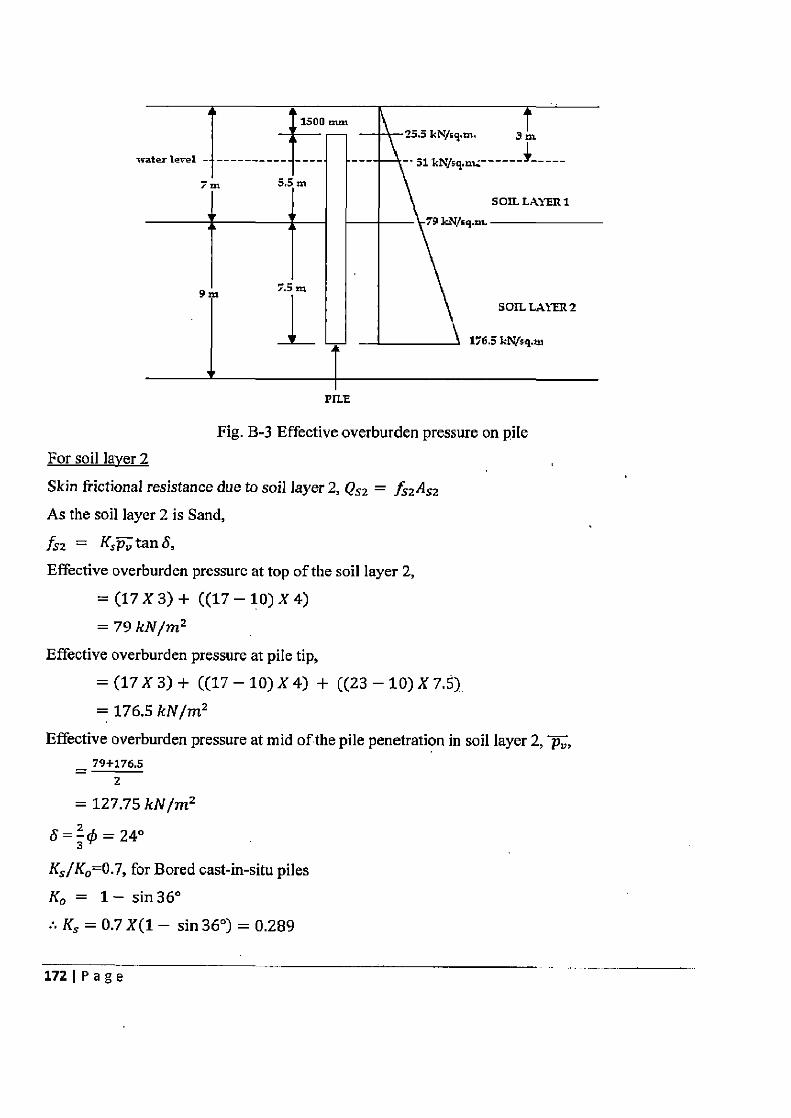
1500 mm
water level _ -----j--- 7m
5.5, m SOIL LAYER 1
kN/sq.m.
9m 7.5 m SOn.LAYER2
176.5 Id' 4q.m
PILE
Fig. B-3 Effective overburden pressure on pile For soil laver 2
Skin frictional resistance due to soil layer 2, Qsz = fszAs2 As the soil layer 2 is Sand,
fsz = K3Pv tan 8, Effective overburden pressure at top of the soil layer 2,
=(17x3)+ ((17-10)x4) = 79 kN/mz
Effective overburden pressure at pile tip, =(17X3)+ ((17-10)X4) + ((23-10)X7.5) = 176.5 kN/m2
Effective overburden pressure at mid of the pile penetration in soil layer 2, p, 79+176.5
= 2
= 127.75 kN/mz
5=3q5 =24°
K5/K0=0.7, for Bored cast-in-situ piles K° = 1— sin36° :• Ks = 0.7 X(1 — sin 36°) = 0.289
172IPage
Hence, f52 = KsPv tan S
= 0.289 X127.75 X tan 24°
= 16.41 kN/m2
A52 =rrX 0.9X7.5= 21.2m2
Q52 = fs2As2
= 16.41 X 21.2
= 348.03 kN
Point bearing resistance of pile, Qp = gpAp For sand,
qp =
where,
pv = Effective overburden pressure at the tip of pile
= 176.5 kN/m2
For 4) = 36°, value of bearing capacity factor Nq = 60 (obtained from Fig. 1 of IS: 2911 (Part 1)
—19793)
qp = (Nq — 1)
= 176.5 X (60 — 1)
= 10413.5 kN/m2
Area of pile at the tip, Ap = it X 0.25 X 0.92 = 0.636 m2
Qp = gpAp
= 10413.5 X0.636
= 6624.8 kN
Hence, Ultimate bearing capacity of a pile Qu = Q, + Qp
= Qsl + Qs2 + Qp = 774.78 + 348.03 + 6624.8
= 7747.6 kN
Taking Factor of safety as 3, safe bearing capacity of pile, Qsa fe = 4°
=2583 Kn
173 1 Page
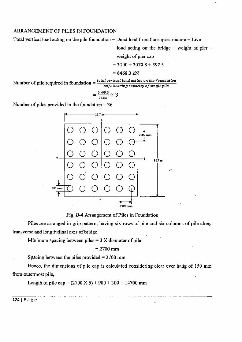
ARRANGEMENT OF PILES IN FOUNDATION
Total vertical load acting on the pile foundation = Dead load from the superstructure + Live
load acting on the bridge + weight of pier +
weight of pier cap
= 3000 + 3070.8 + 397.5
= 6468.3 kN total vertical load acting on the foundation Number of pile required in foundation =
safe bearing capacity of single pile
6468.3 2583
Number of piles provided in the foundation = 36
0 0 0 O O 2700 mm
00000& 0 0 0 0 0 0 T r
1{. . m
0 0 0 0 0 0
0 0 0 0 0. 0 900mm 0 0 0
Fig. B-4 Arrangement of Piles in Foundation
Piles are arranged in grip pattern, having six rows of pile and six columns of pile along
transverse and longitudinal axis of bridge
Minimum spacing between piles = 3 X diameter of pile
= 2700 mm
Spacing between the piles provided = 2700 mm
Hence, the dimensions of pile cap is calculated considering clear over hang of 150 mm
from outermost pile,
Length of pile cap = (2700 X 5) + 900 + 300 = 14700 mm
1741 Page
Width of pile cap = (2700 X 5) + 900 + 300 = 14700 mm
DISTRIBUTION OF LOADS ON PILE
Load on pile ith pile Q; = n + x2 ( + £x y Moment Myy & M,, is calculated at the soffit of pile cap,
Considering the seismic effect along longitudinal direction
Moment about longitudinal axis of bridge, Myy = Eccentric moment due to live load about
longitudinal axis
= 377.6 kNm
Moment about transverse axis of bridge, M,, = Eccentric moment due to live load about
longitudinal axis + Moment due to braking effort
+ Moment due to resistance at bearings +
Moment due to horizontal shear force +
Moment due to seismic effect
= 192.5 + 1120 + 248.4 + 2665 + 6090.2
= 10316 kNm
Vertical load acting on the pile foundation, Q = 14571.7 kN
'xZ = 2X(1.352 X6+4.052 X6+6.752 X6) = 765.5m2
Eyz =2X(1.352 X6+4.052X6+6.752 X6) = 765.5 m2
Pile at distance x; = 6.75 & y; = 6.75 from the longitudinal and transverse axis of bridge
respectively, is carrying the maximum load. 14571.7 377.6 X13.5 10316 X13.5
Hences load on the pile Q; _ + + 36 765.5 765.5
= 499 kN < Qsafe. Hence Ok.
SAFE BEARING CAPACITY OF PILE GROUP
Ultimate bearing capacity of pile group, Qg = fsAs + gvAp
The pile group is penetrated into the two soil layers. Hence, its ultimate bearing capacity is
dependent on the properties of both the soils.
For soil layer I
Skin frictional resistance due to soil layer 1, Qsi = fs1As1
As the soil layer I is Clay,
In = ac,, , But for pile group a = 1
175 1 Page
Undrained cohesion of soil, cu = 120 kN/m2
120 kN/m2
Plan dimensions of pile group are,
Length of pile group = (2.7 X 5) + 0.9 = 14.4 m
Width of pile group = (2.7 X 5) + 0.9 = 14.4 m
AS, = 4 X 14.4 X 5.5 = 316.8 m2
Qsi = fsiAsi
= 120X316.8
tIIJfi~I
For soil laver 2
Skin frictional resistance due to soil layer 2, Q52 = fs2As2
As the soil layer 2 is Sand,
fs2 = K5 tan q5,
For pile group, a' = 1, Hence, Ks = Ko
Effective overburden pressure at mid of the pile group penetration in soil layer 2, p, ,
= 127.75 kN/m2
\KS = 1— sin 36°
Hence, fs2 = Ksp„ tan 0
= (1 — sin 36°) X127.75 X tan 36°
= 38.26 kN/m2
AS2 =4X14.4X7.5=432m2
QS2 = fs2As2
= 38.26X 432
= 16528 kN
Point bearing resistance of pile group, QP = gpAp
For sand,
qp = Pv(Nq — 1),
where,
p„ = Effective overburden pressure at the bottom of pile group
= 176.5 kN/m2
1761 Page
For 4) = 36°, value of bearing capacity factor Nq = 60 (obtained from Fig. 1 of IS: 2911
(Part 1) — 19793)
qp = Pv(Nq — 1)
= 176.5X(60-1)
= 10413.5 kN/m2
Area of pile group at the bottom, Ap = 14.4 X 14.4 = 207.4 rriz
Qp = gpAp
= 10413.5 X 207.4
= 2159343 kN
Hence, Ultimate bearing capacity of a pile group Qg = Qs + Qp
= Qsl + Qs2 + Qp
= 38016+165284-2159343
= 2213887 kN
Safe bearing capacity of pile group shall be taken as smaller of the two values given below: rlQu — 36X 7747.6 =92971 FOS 3
Qg _ 2213887 = 737963 FOS 3
Hence, the Safe bearing capacity of pile group is 92971 kN > Total vertical load acting on the
pile. Hence, Safe.
LATERAL LOAD ANALYSIS OF PILE The lateral load capacity of the pile is estimated as per the layer of soil situated at the
ground level as it will have the major contribution in the lateral load capacity of pile.
As the top most soil layer is normally consolidated clay,
5 Ef T= El
Ylh
where, E = 5000 f~k = 25000 MPa
I_ nx 0.9k=0.0322m4 &
644
77h = 450 kN/m3, for normally loaded clays
Hence, T = 4.47
As the pile is completely embedded into the unscourable ground, Ll = 0
1771 Page
L1 =0 T
From Figure 2 of IS: 2911 (Part 1)-19793, depth of fixity Lr= 9.72 m Here, number of piles provided in foundation is 36 i.e. more than 3
:• The pile head is considered as fixed head pile Lateral load capacity of fixed head pile is calculated as,
12EIY — (Li+Lf )3
where, Y = limiting lateral deflection of pile head,
= 5 mm, for bridge substructures 12 X 25000 X 0.0322 X 0.005 _ _ 52.S9 kN (0+9.72)3
Actual lateral acting on the pile is 49.1 kN < 52.59 kN Hence, Safe. The fixed end moment of the equivalent cantilever is given by:
Qi+ (L L f~ M F =
2 for fixed head pile
= 52.59 X (0+9.72) = 255.6 kNm 2
Reduction factor, m as obtained from Figure 3 of IS: 2911 (Part 1)- 19793 is 0.82 Hence, the actual maximum moment, M = m (MF)
= 0.82X255.6 =209.6kNm STRUCTURAL DESIGN OF PILE
Axial load acting on pile, P = 499 kN & Moment acting on pile, M = 209.6 kNm :•Pu =1.5X499=748.5kN
e 13X209.6 314.4 kNm
Pu
f koz 0.037 & f ko3 = 0.0173
Referring to SP:16 (1980)9,
For koZ = 0.037, f k p3 0.0173 & d'/D = 0.10
p = 0.005 fck
Hence, p = 0.125%
Area of steel required = 0.1zs X '—` X 900' = 792 mm2 100 4
1781Page
Minimum area of steel = 0.4% of gross-sectional area of pile 0.4
ioo X 4 X 9002 = 2545 mm2
:. Minimum area of steel governs,
Provide 20 mm dia. bars as longitudinal reinforcement in pile 2545 Number of 20 mm dia. bars required = 4 x202 = 8
Hence, 9 bars of 20 mm diameter are provided in piles as longitudinal reinforcement Lateral ties of 6 mm are provided at the spacing of 300 mm
Diameter of lateral ties i.e. 6mm < 5 mm, and,
-96mm.
Spacing between lateral: 900 mm, and,
ties ' 320 mm, and,
300 mm. SETTLEMENT OF PILE GROUP
The point bearing resistance of pile has major contribution in bearing capacity of pile.
Hence, the piles are considered as end bearing piles.
As shown in Fig. B-5, the fictitious raft is situated in sand layer at the depth of 12 m
depth below ground level. On the basis of 11-I: 2V dispersion of load, the plan dimensions of raft
are decided as:
Length of raft = 14.4 + 5 = 19.4 in
Width of raft = 14.4 + 5 = 19.4 m
The soil below the raft is sand. Hence, De-Beer and Marten method (1957)22 is used for estimating settlement of pile group in sand.
St = 2.303 C log10 (p" +API Pt, J
where, p„ = mean effective overburden pressure for the layer, 144+196
= 170 kN/m2 2
_ 14571.66 _ 2 p (19.4+2)x(19.4+2)
31.82 kN/rn
C = 1.5q, _ 1.5X2800 = 132 Ap 31.82
Sj = 2.303X 132
X 1og10 ((1701701.62)
1791 Page
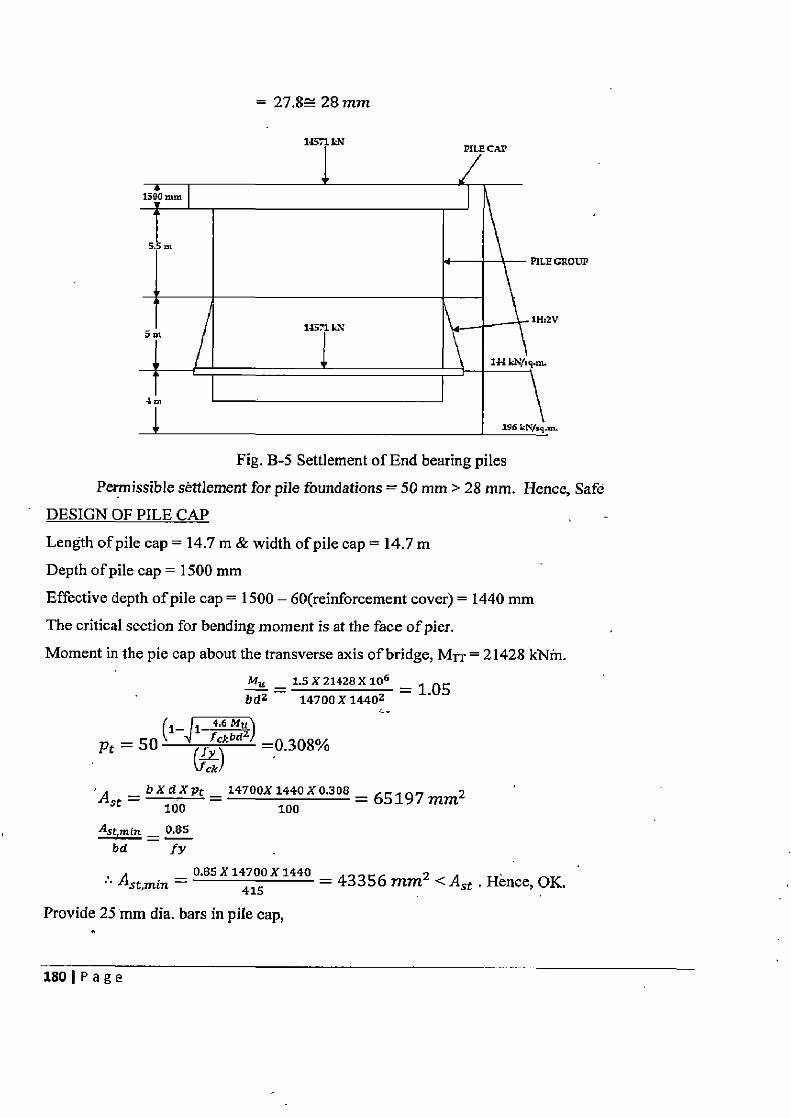
= 27.8= 28 mm
:ROUP
Fig. B-5 Settlement of End bearing piles
Permissible settlement for pile foundations = 50 mm > 28 mm. Hence, Safe DESIGN OF PILE CAP
Length of pile cap = 14.7 m & width of pile cap = 14.7 m
Depth of pile cap = 1500 mm
Effective depth of pile cap = 1500 — 60(reinforcement cover) = 1440 mm The critical section for bending moment is at the face of pier.
Moment in the pie cap about the transverse axis of bridge, MTT = 21428 kNm. Mu _ 1.5 X21428X106
bd? 14700 X 1440? = 1.05
r1_ 1 4.6
Pt = 50 l 1/ kbdz =0.308% v ck'
Ast _ bXdXpt = 14700X 1440X 0.308 = 65197 mm2
100 100
Ast,min _ 0.85 bd fy
0.85 X 14700 X 1440
Ast,min = 415 = 43356 mm2 <Ast . Hence, OK.
Provide 25 mm di a. bars in pile cap,
180IPage
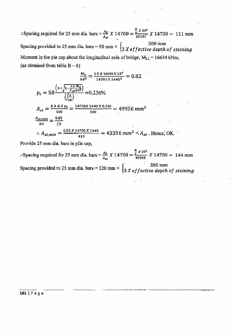
n :.Spacing required for 25 mm dia. bars = A° X 14700 =
y
651 97 X 14700 = 111 mm
Spacing provided to 25 mm dia. bars = 90 mm < 300 ritm {3 X of fective depth of steining
Moment in the pie cap about the longitudinal axis of bridge, MLL= 16634 kNin.
(as obtained from table B — 6) Mu _ 1.5 X 16634 X 10 6 = 0.82 bd2 14700 X 1440 2
1 .6 Mn — 1 4 4 pt = 50k ` =0.236%
Vck/ A _ bXdXpt — 1470OX1440X0.236 _ 49956mm2 st — 100 100
Ast,mtn _ 0.85 lid fy
A _ CASX14700X1440 = 43356mm2 <A Hence`OK. st,min — 415 st s
Provide 25 mm dia. bars in pile cap,
n X252 :.Spacing required for 25 mm dia. bars = A° X 14700 = 49956 X 14700 = 144 mm
sc
Spacing provided to 25 mm dia. bars -- 120 mm < { 300 mm
3 X of fective depth of steining
181 I Page
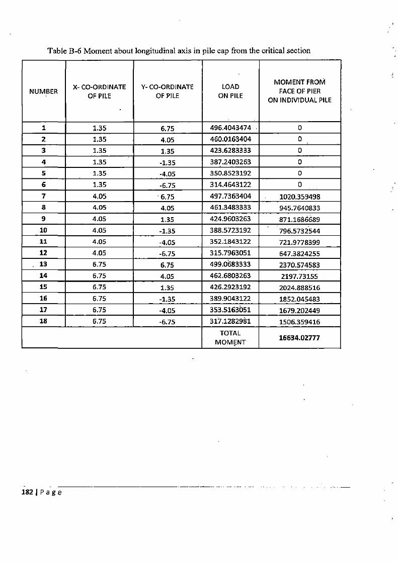
Table B-6 Moment about longitudinal axis in pile cap from the critical section
NUMBER X- CO-ORDINATE
OF PILE Y- CO-ORDINATE
OF PILE LOAD
ON PILE
MOMENT FROM FACE OF PIER
ON INDIVIDUAL PILE
1 1.35 6.75 496.4043474 0
2 1.35 4.05 460.0163404 0
3 1.35 1.35 423.6283333 0
4 1.35 -1.35 387.2403263 0
5 1.35 -4.05 350.8523192 0
6 1.35 -6.75 314.4643122 0
7 4.05 6.75 497.7363404 1020.359498
8 4.05 4.05 461.3483333 945.7640833
9 4.05 1.35 424.9603263 871.1686689
30 4.05 -1.35 388.5723192 796.5732544
11 4.05 -4.05 352.1843122 721.9778399
12 4.05 -6.75 315.7963051 647.3824255
13 6.75 6.75 499.0683333 2370.574583
14 6.75 4.05 462.6803263 2197.73155
15 6.75 1.35 426.2923192 2024.888516
16 6.75 -1.35 389.9043122 1852.045483
17 6.75 -4.05 353.5163051 1679.202449
18 6.75 -6.75 317.1282981 1506.359416
TOTAL MOMENT
16634.02777
182IPage

Check of two-way shear
The critical section for two way shear is effective depth/2 i.e. 720 mm away from the face of pier. The two- way shear developed in pile cap is as calculated in Table B-7. Hence, for two-way shear
Shear force = 12952 kN
Nominal Shear Stress = 12452 X 1000 = 0.62 N/mm2 4 X (4090+1440)X1440
Permissible shear stress, r,' = ksz,, where ks = 1
& r, = 0.25 f~k = 1.25> Nominal shear stress. Hence OK.
Check of one-way shear
The critical section for one way shear is effective depth i.e. 720 mm away from the face
of pier. The one - way shear developed in pile cap is as calculated in Table 6.14.
For shear force acting at the critical section along transverse axis of bridge
Shear force = 5730 kN
Nominal Shear Stress = 5730 x 1000 = 0.27 N/mm2 14700 X1440
As per Table 23 of IS: 456-2000', for 0.34% steel,
Permissible shear stress, r, = 0.27N/mm2 . Hence, OK.
For shear force acting at the critical section along longitudinal axis of bridge
Shear force = 4889 kN
Nominal Shear Stress = 14700 X1440 = 0.23 N/mm2
As per Table 23 of IS: 456-2000', for 0.26% steel,
Permissible shear stress, a„ = 0.24N/mm7 <, Nominal Shear Stress. Hence, OK.
I
183IPage
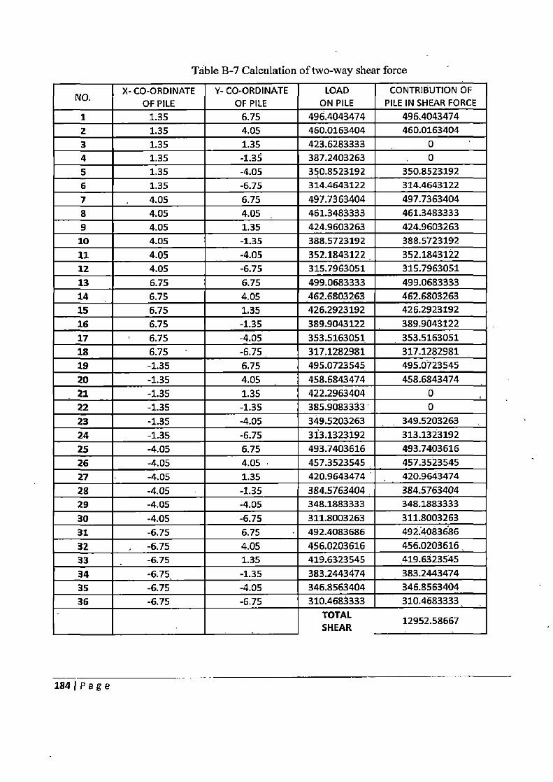
Table B-7 Calculation of two-way shear force
X- CO-ORDINATE OF PILE
NO.
Y-CO-ORDINATE OF PILE
LOAD ON PILE
CONTRIBUTION OF PILE IN SHEAR FORCE
1 1.35 6.75 496.4043474 496.4043474
2 1.35 4,05 460.0163404 460.0163404
3 1.35 1.35 423.6283333 0
4 1.35 -1.35 387.2403263 0
5 1.35 -4.05 350.8523192 350.8523192
6 1.35 -6.75 314.4643122 314.4643122
7 4.05 6.75 497.7363404 497.7363404
8 4.05 4.05 _ 461.3483333 461.3483333
9 4.05 1.35 424.9603263 424.9603263
10 4.05 -1.35 388.5723192 388.5723192
11 4.05 -4.05 352.1843122 352.1843122
12 4.05 -6.75 315.7963051 315.7963051
13 6.75 6.75 499.0683333 499.0683333
14 6.75 4.05 462.6803263 462.6803263
15 6.75 1.35 426.2923192 426.2923192
16 6.75 -1.35 389.9043122 389.9043122
17 6.75 -4.05 353.5163051 353.5163051
18 6.75 -6.75 317.1282981 317.1282981
19 -1.35 6.75 495.0723545 495.0723545
20 -1.35 4.05 458.6843474 458.6843474
21 -1.35 1.35 422.2963404 0
22 -1.35 -1.35 385.9083333 0
23 -1.35 -4.05 349.5203263 349.5203263
24 -1.35 -6.75 313.1323192 313.1323192
25 -4.05 6.75 493.7403616 493.7403616
26 -4.05 4.05 457.3523545 457.3523545
27 -4.05 1.35 420.9643474 420.9643474
28 -4.05 - -1.35 384.5763404 384.5763404
29 -4.05 -4.05 348.1883333 348.1883333
30 -4.05 -6.75 311.8003263 311.8003263
31 -6.75 6.75 492.4083686 492.4083686
32 -6.75 4.05 456.0203616 456.0203616.
33 -6.75 1.35 419.6323545 419.6323545
34 -6.75 -1.35 383.2443474 383.2443474
35 -6.75 -4.05 346.8563404 346.8563404
36 -6.75 -6.75 310.4683333 310.4683333
TOTAL 12952.58667
SHEAR
184IPage
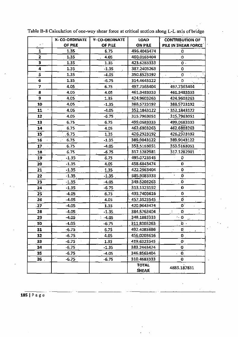
Table B-8 Calculation of one-way shear force at critical section along L-L axis of bridge
X- CO-ORDINATE OF PILE
Y- CO-ORDINATE OF PILE
LOAD ON PILE
CONTRIBUTION OF PILE IN SHEAR FORCE
1 1.35 6.75 496.4043474 0 2 1.35 . 4.05 460.0163404 0 3 1.35 1.35 423.6283333 0 4 1.35 -1.35 387.2403263 0 5 1.35 -4.05 350.8523192 0 6 1.35 -6.75 314.4643122 0 7 4.05 6.75 497.7363404 497.7363404 8 4.05 4.05 461.3483333 461.3483333 9 4.05 1.35 424.9603263 424.9603263
10 4.05 -1.35 388.5723192 388.5723192
11 4.05 -4.05 352.1843122 352.1843122 12 4.05 -6.75 315.7963051 315.7963051
13 6.75 6.75 499.0683333 499.0683333 14 6.75 4.05 462.6803263 462.6803263
15 6.75 1.35 426.2923192 426.2923192
16 6.75 -1.35 389.9043122 389.9043122
17 6.75 -4.05 353.5163051 353.5163051 18 6.75 -6.75 317.1282981 317.1282981
19 -1.35 6.75 495.0723545 0
20 -1.35 4.05 458.6843474 0
21 -1.35 1.35 422.2963404 0
22 -1.35_ -1.35 - 385.9083333 0 23 -1.35 -4.05 349.5203263 0
24 -1.35 -6.75 313.1323192 0
25 -4.05 6.75 493.7403616 0
26 -4.05 4.05 457.3523545 0 27 -4.05 1.35 420.9643474 0
28 -4.05 -1.35. 384.5763404 Q _
29 -4.05 -4.05 348.1883333 0
30 -4.05 =6:75 811.8003263 - 0 31 -6.75 6.75 492.4083686 0'
32 -6.75 4.05 456.0203616 0 33 -6.75 1.35 419.6323545 0' 34 -6.75 -1.35 383.2443474 0 35 -6.75 -4.05 346.8563404 . 0, 36 . -6.75 -6.75 310.4683333 0
TOTAL SHEAR
4889.187831
185 I P a g e
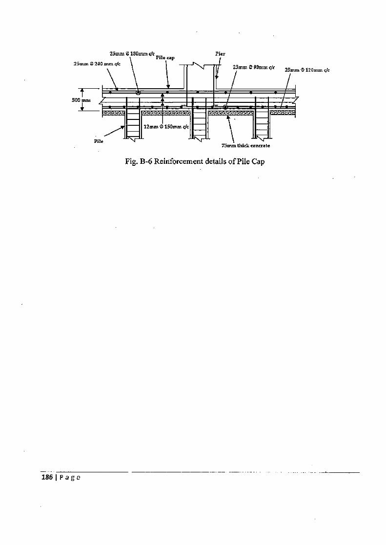
25mm a 180mm c/c Pier
\
File leap
25mm 2 230 mm S/c 25m¢t 4 90mm c/< 23nunt120mm c c
500 mm
4 12mw a 150mm c%
Tmm thick concrete
Fig. B-6 Reinforcement details of Pile Cap
Pile
1861 Page
Related Documents


