This article has been accepted for inclusion in a future issue of this journal. Content is final as presented, with the exception of pagination. IEEE/ASME TRANSACTIONS ON MECHATRONICS 1 Analysis and Design of a Reconfigurable 3-DoF Parallel Manipulator for Multimodal Tasks Matteo-Claudio Palpacelli, Luca Carbonari, Giacomo Palmieri, and Massimo Callegari Abstract—This paper presents the design of a reconfigurable 3-DoF parallel kinematics manipulator. The main feature of the device is the ability to change the mobility of its moving platform from pure translation to pure rotation. The manipulator kinemat- ics is conceived so that, when a particular configuration of the manipulator is reached, the transition between the two working modes is possible by changing the configuration of a metamorphic universal joint, which is used to connect the legs of the manipula- tor with the moving platform. The mechanical design of the joint, which is in fact a lockable spherical joint, is illustrated. With the joint integrated into the robot architecture, an instantaneous over- constrained kinematics is exploited to manage the phase of recon- figuration of the whole mechatronic device. A kineto-static analysis provides information about the influence of geometric parameters on its functional design. The manipulator shows simple kinematics and statics models, as well as good kinematic and static perfor- mances. Eventually, the versatility of the manipulator is shown by proposing some advanced manufacturing applications in which it could find use. Index Terms—Lockable joint, metamorphic mechanism, mobil- ity analysis, parallel robot, reconfigurable manipulator. I. INTRODUCTION T HE word kinematotropy was first introduced in 1996 by Wohlhart [1], who felt the need to give a name to a pecu- liar property of some mechanisms, namely the ability to change their mobility according to changes in the position variables. This behavior occurs when a mechanism passes through a singu- lar configuration, in which an infinitesimal mobility is allowed. The concept can be extended from linkage level to more so- phisticated systems, giving rise to what are called metamorphic mechanisms [2]. Both expressions are used to describe mechan- ical systems, which are to some extent reconfigurable. Such property can be exploited profitably in minor mobility parallel Manuscript received April 1, 2014; revised August 1, 2014; accepted October 6, 2014. Recommended by Technical Editor W. Lin. M. Palpacelli, L. Carbonari, and M. Callegari are with the Department of Industrial Engineering and Mathematical Sciences, Polytechnic University of Marche, Ancona 60131, Italy (e-mail: [email protected]; l.carbonari@ univpm.it; [email protected]). G. Palmieri is with the eCampus University, Novedrate 22060, Italy (e-mail: [email protected]). Color versions of one or more of the figures in this paper are available online at http://ieeexplore.ieee.org. This paper has supplementary downloadable multimedia material available at http://ieeexplore.ieee.org provided by the authors. This includes two videos. The first video, “3-CPU Translation,” can be described as follows: Reconfigurable 3-CPU Robot in the pure translation mode: a sinusoidal law of motion executed by the three linear motors generates a pure translation of the moving platform of the manipulator. The second video, “3-CPU Rotation.wmv,” can be described as follows: Reconfigurable 3-CPU Robot in the pure rotation mode: the same law of motion executed by the motors generates a pure rotation of the moving platform of the manipulator. Digital Object Identifier 10.1109/TMECH.2014.2365616 kinematics manipulators [3]. In fact, a reduced mobility has been often preferred to a full 6-DoF mobility because of the clear ad- vantages in terms of cost, simplicity of kinematics models, and of their implementation in control systems. However, advanced and intelligent manufacturing systems are increasingly oriented toward the use of adaptive and smart equipment, able to meet quickly market changes. Therefore, the idea of combining different mobilities in a single mechanism, increasing its versatility while maintaining simplicity in its kinematics model, has attracted for years sev- eral researchers [4]–[6]. Many examples of applications of kine- matotropic linkages to parallel kinematics manipulators can be found in the recent literature [7], [8]: the result is typically a ma- nipulator whose end effector has the ability to perform different kinds of motion, for example, pure translation, pure rotation or a composition of translations and rotations. An attempt to provide a classification about the types of re- configurability is made by Xi et al. [9], who mentioned ge- ometry morphing, topology morphing, and group morphing.A further concept, which is often associated to reconfigurable ma- nipulators is the modularity [10]. It can be thought of as the existence of building blocks, which can be elementary modules or more complex elements obtained with a specific sequence of joints. Typically a reconfigurable manipulator results from their composition. The analysis and synthesis of reconfigurable manipulators is supported by several mathematical tools, from the screw theory [11] and Lie algebra [12] to algebraic geometry [13]. The latter has been used by the Authors to investigate the working modes of a 3-DoF parallel manipulator, a tripod provided with CPU leg kinematics, namely a sequence of Cylindrical-Prismatic- Universal joints from the fixed frame to the mobile platform [14], [15]. The study was motivated by the results of previous works on such kinematics [16], [17], which highlighted some interesting features: a different arrangement of the joint axes, maintaining the same sequence of joints for each leg, provides two different mobilities, respectively, of pure translation and rotation. Two prototypes were realized accordingly, but their different mechanical structure makes them in effect two distinct manipulators. The study about the 3-CPU kinematics has revealed that the reconfigurability of this architecture depends on the change of configuration of the universal joints, which connect the legs with the moving platform. The desired universal joint can be thought of as a spherical joint where one of the three axes is locked alternatively [18], [19]. The resulting reconfigurable universal joint produces an essential change on the kinematic behavior of the platform, with a transition from a translational to a rotational working mode. 1083-4435 © 2014 IEEE. Personal use is permitted, but republication/redistribution requires IEEE permission. See http://www.ieee.org/publications standards/publications/rights/index.html for more information.

Welcome message from author
This document is posted to help you gain knowledge. Please leave a comment to let me know what you think about it! Share it to your friends and learn new things together.
Transcript
This article has been accepted for inclusion in a future issue of this journal. Content is final as presented, with the exception of pagination.
IEEE/ASME TRANSACTIONS ON MECHATRONICS 1
Analysis and Design of a Reconfigurable 3-DoFParallel Manipulator for Multimodal Tasks
Matteo-Claudio Palpacelli, Luca Carbonari, Giacomo Palmieri, and Massimo Callegari
Abstract—This paper presents the design of a reconfigurable3-DoF parallel kinematics manipulator. The main feature of thedevice is the ability to change the mobility of its moving platformfrom pure translation to pure rotation. The manipulator kinemat-ics is conceived so that, when a particular configuration of themanipulator is reached, the transition between the two workingmodes is possible by changing the configuration of a metamorphicuniversal joint, which is used to connect the legs of the manipula-tor with the moving platform. The mechanical design of the joint,which is in fact a lockable spherical joint, is illustrated. With thejoint integrated into the robot architecture, an instantaneous over-constrained kinematics is exploited to manage the phase of recon-figuration of the whole mechatronic device. A kineto-static analysisprovides information about the influence of geometric parameterson its functional design. The manipulator shows simple kinematicsand statics models, as well as good kinematic and static perfor-mances. Eventually, the versatility of the manipulator is shown byproposing some advanced manufacturing applications in which itcould find use.
Index Terms—Lockable joint, metamorphic mechanism, mobil-ity analysis, parallel robot, reconfigurable manipulator.
I. INTRODUCTION
THE word kinematotropy was first introduced in 1996 byWohlhart [1], who felt the need to give a name to a pecu-
liar property of some mechanisms, namely the ability to changetheir mobility according to changes in the position variables.This behavior occurs when a mechanism passes through a singu-lar configuration, in which an infinitesimal mobility is allowed.The concept can be extended from linkage level to more so-phisticated systems, giving rise to what are called metamorphicmechanisms [2]. Both expressions are used to describe mechan-ical systems, which are to some extent reconfigurable. Suchproperty can be exploited profitably in minor mobility parallel
Manuscript received April 1, 2014; revised August 1, 2014; accepted October6, 2014. Recommended by Technical Editor W. Lin.
M. Palpacelli, L. Carbonari, and M. Callegari are with the Department ofIndustrial Engineering and Mathematical Sciences, Polytechnic University ofMarche, Ancona 60131, Italy (e-mail: [email protected]; [email protected]; [email protected]).
G. Palmieri is with the eCampus University, Novedrate 22060, Italy (e-mail:[email protected]).
Color versions of one or more of the figures in this paper are available onlineat http://ieeexplore.ieee.org.
This paper has supplementary downloadable multimedia material available athttp://ieeexplore.ieee.org provided by the authors. This includes two videos. Thefirst video, “3-CPU Translation,” can be described as follows: Reconfigurable3-CPU Robot in the pure translation mode: a sinusoidal law of motion executedby the three linear motors generates a pure translation of the moving platform ofthe manipulator. The second video, “3-CPU Rotation.wmv,” can be describedas follows: Reconfigurable 3-CPU Robot in the pure rotation mode: the samelaw of motion executed by the motors generates a pure rotation of the movingplatform of the manipulator.
Digital Object Identifier 10.1109/TMECH.2014.2365616
kinematics manipulators [3]. In fact, a reduced mobility has beenoften preferred to a full 6-DoF mobility because of the clear ad-vantages in terms of cost, simplicity of kinematics models, andof their implementation in control systems. However, advancedand intelligent manufacturing systems are increasingly orientedtoward the use of adaptive and smart equipment, able to meetquickly market changes.
Therefore, the idea of combining different mobilities in asingle mechanism, increasing its versatility while maintainingsimplicity in its kinematics model, has attracted for years sev-eral researchers [4]–[6]. Many examples of applications of kine-matotropic linkages to parallel kinematics manipulators can befound in the recent literature [7], [8]: the result is typically a ma-nipulator whose end effector has the ability to perform differentkinds of motion, for example, pure translation, pure rotation ora composition of translations and rotations.
An attempt to provide a classification about the types of re-configurability is made by Xi et al. [9], who mentioned ge-ometry morphing, topology morphing, and group morphing. Afurther concept, which is often associated to reconfigurable ma-nipulators is the modularity [10]. It can be thought of as theexistence of building blocks, which can be elementary modulesor more complex elements obtained with a specific sequence ofjoints. Typically a reconfigurable manipulator results from theircomposition.
The analysis and synthesis of reconfigurable manipulators issupported by several mathematical tools, from the screw theory[11] and Lie algebra [12] to algebraic geometry [13]. The latterhas been used by the Authors to investigate the working modesof a 3-DoF parallel manipulator, a tripod provided with CPUleg kinematics, namely a sequence of Cylindrical-Prismatic-Universal joints from the fixed frame to the mobile platform[14], [15]. The study was motivated by the results of previousworks on such kinematics [16], [17], which highlighted someinteresting features: a different arrangement of the joint axes,maintaining the same sequence of joints for each leg, providestwo different mobilities, respectively, of pure translation androtation. Two prototypes were realized accordingly, but theirdifferent mechanical structure makes them in effect two distinctmanipulators.
The study about the 3-CPU kinematics has revealed that thereconfigurability of this architecture depends on the change ofconfiguration of the universal joints, which connect the legs withthe moving platform. The desired universal joint can be thoughtof as a spherical joint where one of the three axes is lockedalternatively [18], [19]. The resulting reconfigurable universaljoint produces an essential change on the kinematic behavior ofthe platform, with a transition from a translational to a rotationalworking mode.
1083-4435 © 2014 IEEE. Personal use is permitted, but republication/redistribution requires IEEE permission.See http://www.ieee.org/publications standards/publications/rights/index.html for more information.
This article has been accepted for inclusion in a future issue of this journal. Content is final as presented, with the exception of pagination.
2 IEEE/ASME TRANSACTIONS ON MECHATRONICS
Several examples of lockable joints can be found in serialand parallel manipulators [20]–[26], where the reconfigurablejoint can be locked and released online or manually in orderto operate a change of the robot mobility, or alternatively toavoid singularities and to manage singularity loci [27]. In thispaper, the joint reconfiguration is driven electronically; more-over, the concept of instantaneous overconstrained kinematicsis exploited in order to realize an automatic reconfiguration ofthe robot kinematics, preventing the use of external fixturestypically used to keep the robot in position during the switchphase. This feature makes the proposed mechatronic device par-ticularly suited to intelligent manufacturing applications, whereaccuracy and adaptability are essential elements.
II. KINEMATIC MODEL
The reconfigurable 3-CPU manipulator is a parallel kinemat-ics machine made up of a fixed base and a mobile platformconnected by means of three identical actuated legs. The ma-nipulator takes its name from the kinematics of the legs, in facta sequence of Cylindrical-Prismatic-Universal joints is used toassemble the two members of each leg together and with thefixed and mobile platforms.
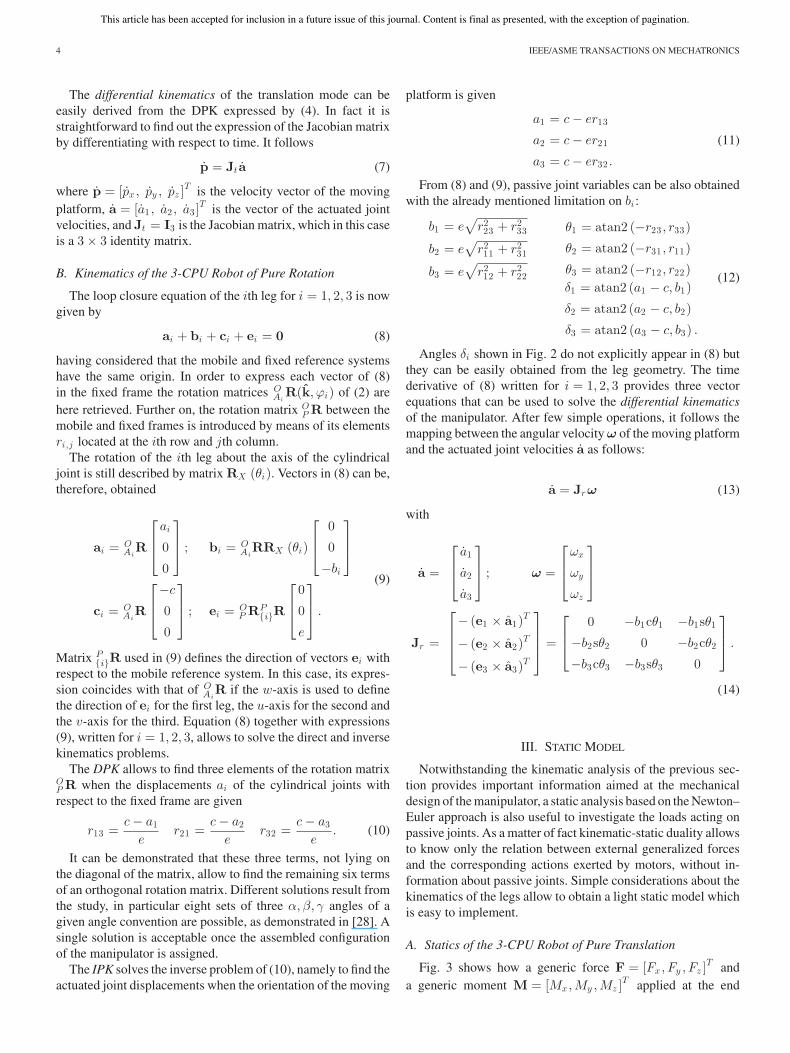
The linear displacement of the cylindrical pairs is actuated,driving the three degrees of freedom of the mobile platform:a reconfiguration of the universal joints allows to change themobility of the platform from pure translation to pure rotation. Itfollows that the same three motors can be used to drive the threedegrees of freedom provided by the 3-CPU kinematics, with theopportunity to switch from one mobility to the other accordingto user needs. The change of mobility occurs only at a specificpose of the mobile platform, called “home configuration,” wherethe universal joint configuration can be modified. Figs. 1 and2, respectively, show the sketches of the leg kinematics of the3-CPU robot of pure translation and of pure rotation. In bothdevice configurations a reference system {O;x, y, z} is fixed tothe base frame, whereas a mobile system {P ;u, v, w} is attachedto the moving platform.
The cylindrical joints are mutually orthogonal and directed asthe edges of a cube, therefore, the origin of the fixed referenceframe {O;x, y, z} is chosen for convenience at their intersec-tion, with its unit vectors aligned with their axes. Leg 1 is relatedto the x-axis, leg 2 to the y-axis, and leg 3 to the z-axis. Theprismatic joint that connects the two members of each leg isperpendicular to the related cylindrical joint. They intersect ata point Ai , where a reference system {Ai ;xAi, yAi, zAi} is in-troduced for each leg, with the xAi-axis aligned with the axisof the cylindrical joint and the zAi-axis aligned as the prismaticjoint when the device is in its home configuration, namely whenthe planes defined by the legs overlap with the planes of thefixed Cartesian frame: zx-plane for the first leg, xy-plane forthe second leg, and yz-plane for the third. A further referencesystem {Bi ;xBi, yB i, zB i} is conveniently defined at the centerof the U-joints, with the xBi-axis parallel to xAi and the zBi-axis parallel to the prismatic joint. It follows that xBi and zBi
define together the ith leg plane.It is clear from Figs. 1 and 2 that the U-joint has a dif-
ferent arrangement in the two cases, as a matter of fact the
3-CPU robot of pure translation has the inner revolute axis of theU-joint directed parallel to the cylindrical axis within the sameleg, whereas it can be demonstrated that the outer revolute axishas a fixed orientation with respect to the mobile reference sys-tem. In particular, it coincides with the w-axis for the leg 1, withthe u-axis for the leg 2, and with the v-axis for the leg 3. On thecontrary the 3-CPU robot of pure rotation has the inner revoluteaxis normal to the leg plane, whereas the outer revolute axisalways converges toward the origin P of the mobile frame; itcan be demonstrated that such point remains fixed and coincideswith the origin O of the fixed frame.
Figs. 1 and 2 also show how the transition can be realizedbetween the two kinematic solutions: the home configurationcan be thought of as the common geometry between the two3-CPU configurations, in which all the legs and the movingplatform have the same physical position and orientation intothe Cartesian space. The only difference lies in the directionsof the U-joint axes. More precisely, the analysis proposed in[15] demonstrates that only one solution of direct kinematics iscommon between the two 3-CPU configurations. In particular,if the universal joint is conceived as a lockable spherical jointwith three revolute axes connected in series, the 3-CPU robotsof translation and rotation can be enabled by locking, respec-tively, the second and the first axis. The sequence of revolutejoints encountered from the fixed base to the moving platformis chosen in order to realize the desired U-joints: referring tothe home configuration, the first axis of rotation is aligned withthe axis of the cylindrical joint of the same leg, the second isorthogonal to the leg plane, and the third is orthogonal to theprevious ones.
In order to derive the kinematics equations of the manipulator,which are different according to the setting of the reconfigurableuniversal joints, more details must be given. The geometricalparameters common to the two architectures are shown in Figs. 1and 2.
1) ai: actuated distance between point Ai and the origin Oof the fixed reference system.
2) θi: angle given by the rotation of the leg about the axisof the cylindrical joint, namely about the local xAi-axis,from the home configuration.
3) bi: distance between the axis of the cylindrical joint andthe parallel line passing through the center of the universaljoint.
4) c: distance between the axis of the prismatic joint and thecenter Bi of the universal joint.
5) e: distance between the center of the universal joint andthe origin P of the mobile reference system.
Apart from c and e, which are constant geometric parameters,the other quantities are variable and refer to each ith leg. Theexpressions of active and passive parameters for both 3-CPUmanipulators are given in the following.
A. Kinematics of the 3-CPU Robot of Pure Translation
The loop closure equation of the ith leg for i = 1, 2, 3 isp = ai + bi + ci + ei . (1)
In order to express each vector of (1) in the fixed frame arotation matrix O
AiR(k, ϕi) between the local frame on the ith

This article has been accepted for inclusion in a future issue of this journal. Content is final as presented, with the exception of pagination.
PALPACELLI et al.: ANALYSIS AND DESIGN OF A RECONFIGURABLE 3-DOF PARALLEL MANIPULATOR FOR MULTIMODAL TASKS 3
Fig. 1. 3-CPU robot of pure translation: sketch of the leg kinematics.
Fig. 2. 3-CPU robot of pure rotation: sketch of the leg kinematics.
leg and the fixed frame is defined by means of the axis-anglerepresentation obtained from the Rodrigues’ rotation formula
OAi
R(k, ϕi) = k sin ϕi + (I3 − kkT ) cos ϕi + kkT . (2)
The unit vector k =[1/√
3, 1/√
3, 1/√
3]T
is directed as thediagonal of the cube whose edges are the Cartesian axes of thefixed frame, whereas k is the skew-symmetric matrix form fork. The rotation matrices associated to the first, second, and thirdleg are obtained for ϕ1 = 0◦, ϕ2 = 120◦, ϕ3 = 240◦.
The rotation of the ith leg about the xAi-axis of the cylindricaljoint is given by a conventional RX rotation matrix. Therefore,matrix RX (θi) yields a tilt θi of the leg about the x-axis of thelocal reference system {Ai ;xAi, yAi, zAi}. Vectors of (1) canbe, therefore, obtained as
p =
⎡
⎢⎣
px
py
pz
⎤
⎥⎦ ; ai = O
AiR
⎡
⎢⎣
ai
0
0
⎤
⎥⎦
bi = OAi
RRX (θi)
⎡
⎢⎣
0
0
−bi
⎤
⎥⎦ ; ci = O
AiR
⎡
⎢⎣
−c
0
0
⎤
⎥⎦
ei = OAi
R
⎡
⎢⎣
0
0
e
⎤
⎥⎦ .
(3)
Equation (1) together with expressions (3), written for i =1, 2, 3, allows to solve both the direct and inverse position kine-matics (DPK and IPK).
The DPK allows to find the Cartesian coordinates of the mov-ing platform once the displacements of the cylindrical joints withrespect to the fixed frame are given
px = a1 − c
py = a2 − c
pz = a3 − c. (4)
The IPK solves the actuated joint displacements when theposition coordinates of the moving platform are given
a1 = px + c
a2 = py + c
a3 = pz + c. (5)
From (1) by means of (3) passive joint variables can be alsoobtained, where a single kinematic solution is obtained by im-posing bi ≥ 0
b1 =√
p2y + (e − pz )
2
b2 =√
p2z + (e − px)2
b3 =√
p2x + (e − py )2
θ1 = atan2 (py , e − pz )
θ2 = atan2 (pz , e − px)
θ3 = atan2 (px, e − py ) .
(6)
This article has been accepted for inclusion in a future issue of this journal. Content is final as presented, with the exception of pagination.
4 IEEE/ASME TRANSACTIONS ON MECHATRONICS
The differential kinematics of the translation mode can beeasily derived from the DPK expressed by (4). In fact it isstraightforward to find out the expression of the Jacobian matrixby differentiating with respect to time. It follows
p = Jt a (7)
where p = [px , py , pz ]T is the velocity vector of the moving
platform, a = [a1 , a2 , a3 ]T is the vector of the actuated joint
velocities, and Jt = I3 is the Jacobian matrix, which in this caseis a 3 × 3 identity matrix.
B. Kinematics of the 3-CPU Robot of Pure Rotation
The loop closure equation of the ith leg for i = 1, 2, 3 is nowgiven by
ai + bi + ci + ei = 0 (8)
having considered that the mobile and fixed reference systemshave the same origin. In order to express each vector of (8)in the fixed frame the rotation matrices O
AiR(k, ϕi) of (2) are
here retrieved. Further on, the rotation matrix OP R between the
mobile and fixed frames is introduced by means of its elementsri,j located at the ith row and jth column.
The rotation of the ith leg about the axis of the cylindricaljoint is still described by matrix RX (θi). Vectors in (8) can be,therefore, obtained
ai = OAi
R
⎡
⎢⎣
ai
0
0
⎤
⎥⎦ ; bi = O
AiRRX (θi)
⎡
⎢⎣
0
0
−bi
⎤
⎥⎦
ci = OAi
R
⎡
⎢⎣
−c
0
0
⎤
⎥⎦ ; ei = O
P RP{i}R
⎡
⎢⎣
0
0
e
⎤
⎥⎦ .
(9)
Matrix P{i}R used in (9) defines the direction of vectors ei with
respect to the mobile reference system. In this case, its expres-sion coincides with that of O
AiR if the w-axis is used to define
the direction of ei for the first leg, the u-axis for the second andthe v-axis for the third. Equation (8) together with expressions(9), written for i = 1, 2, 3, allows to solve the direct and inversekinematics problems.
The DPK allows to find three elements of the rotation matrixOP R when the displacements ai of the cylindrical joints withrespect to the fixed frame are given
r13 =c − a1
er21 =
c − a2
er32 =
c − a3
e. (10)
It can be demonstrated that these three terms, not lying onthe diagonal of the matrix, allow to find the remaining six termsof an orthogonal rotation matrix. Different solutions result fromthe study, in particular eight sets of three α, β, γ angles of agiven angle convention are possible, as demonstrated in [28]. Asingle solution is acceptable once the assembled configurationof the manipulator is assigned.
The IPK solves the inverse problem of (10), namely to find theactuated joint displacements when the orientation of the moving
platform is given
a1 = c − er13
a2 = c − er21
a3 = c − er32 .
(11)
From (8) and (9), passive joint variables can be also obtainedwith the already mentioned limitation on bi :
b1 = e√
r223 + r2
33
b2 = e√
r211 + r2
31
b3 = e√
r212 + r2
22
θ1 = atan2 (−r23 , r33)
θ2 = atan2 (−r31 , r11)
θ3 = atan2 (−r12 , r22)δ1 = atan2 (a1 − c, b1)
δ2 = atan2 (a2 − c, b2)
δ3 = atan2 (a3 − c, b3) .
(12)
Angles δi shown in Fig. 2 do not explicitly appear in (8) butthey can be easily obtained from the leg geometry. The timederivative of (8) written for i = 1, 2, 3 provides three vectorequations that can be used to solve the differential kinematicsof the manipulator. After few simple operations, it follows themapping between the angular velocity ω of the moving platformand the actuated joint velocities a as follows:
a = Jrω (13)
with
a =
⎡
⎢⎣
a1
a2
a3
⎤
⎥⎦ ; ω =
⎡
⎢⎣
ωx
ωy
ωz
⎤
⎥⎦
Jr =
⎡
⎢⎢⎣
− (e1 × a1)T
− (e2 × a2)T
− (e3 × a3)T
⎤
⎥⎥⎦ =
⎡
⎢⎣
0 −b1cθ1 −b1sθ1
−b2sθ2 0 −b2cθ2
−b3cθ3 −b3sθ3 0
⎤
⎥⎦ .
(14)
III. STATIC MODEL
Notwithstanding the kinematic analysis of the previous sec-tion provides important information aimed at the mechanicaldesign of the manipulator, a static analysis based on the Newton–Euler approach is also useful to investigate the loads acting onpassive joints. As a matter of fact kinematic-static duality allowsto know only the relation between external generalized forcesand the corresponding actions exerted by motors, without in-formation about passive joints. Simple considerations about thekinematics of the legs allow to obtain a light static model whichis easy to implement.
A. Statics of the 3-CPU Robot of Pure Translation
Fig. 3 shows how a generic force F = [Fx, Fy , Fz ]T and
a generic moment M = [Mx,My ,Mz ]T applied at the end
This article has been accepted for inclusion in a future issue of this journal. Content is final as presented, with the exception of pagination.
PALPACELLI et al.: ANALYSIS AND DESIGN OF A RECONFIGURABLE 3-DOF PARALLEL MANIPULATOR FOR MULTIMODAL TASKS 5
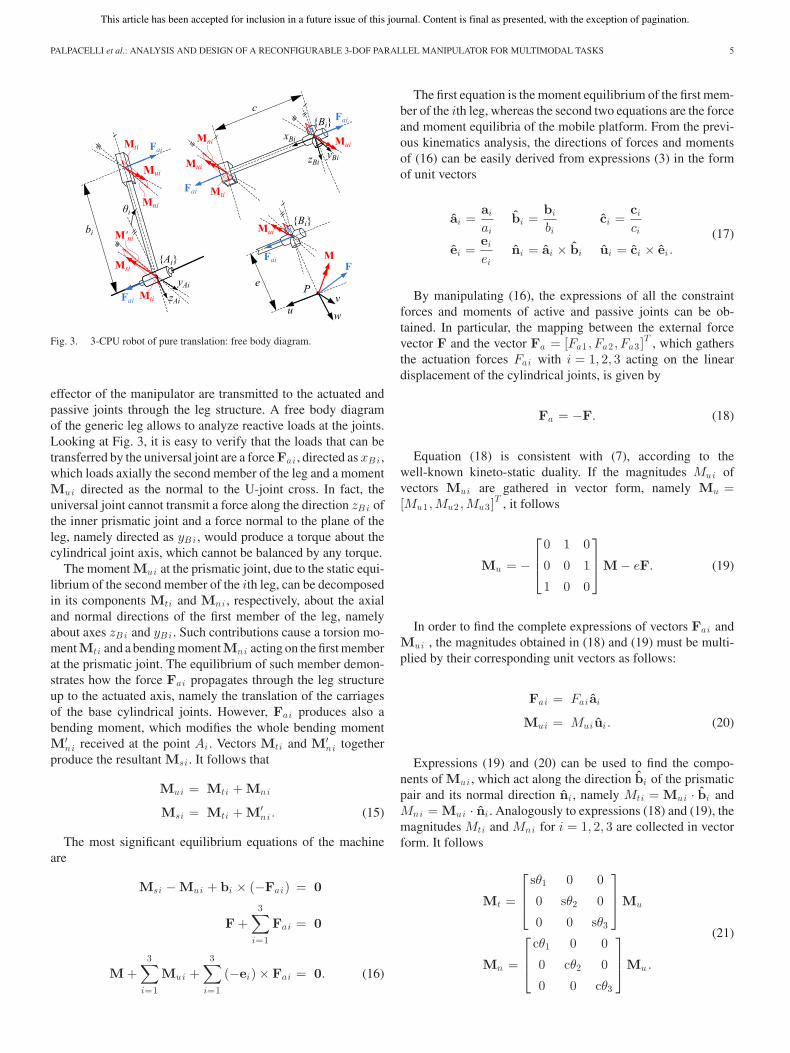
Fig. 3. 3-CPU robot of pure translation: free body diagram.
effector of the manipulator are transmitted to the actuated andpassive joints through the leg structure. A free body diagramof the generic leg allows to analyze reactive loads at the joints.Looking at Fig. 3, it is easy to verify that the loads that can betransferred by the universal joint are a force Fai , directed as xBi ,which loads axially the second member of the leg and a momentMui directed as the normal to the U-joint cross. In fact, theuniversal joint cannot transmit a force along the direction zBi ofthe inner prismatic joint and a force normal to the plane of theleg, namely directed as yBi , would produce a torque about thecylindrical joint axis, which cannot be balanced by any torque.
The moment Mui at the prismatic joint, due to the static equi-librium of the second member of the ith leg, can be decomposedin its components Mti and Mni , respectively, about the axialand normal directions of the first member of the leg, namelyabout axes zBi and yBi . Such contributions cause a torsion mo-mentMti and a bending momentMni acting on the first memberat the prismatic joint. The equilibrium of such member demon-strates how the force Fai propagates through the leg structureup to the actuated axis, namely the translation of the carriagesof the base cylindrical joints. However, Fai produces also abending moment, which modifies the whole bending momentM′
ni received at the point Ai . Vectors Mti and M′ni together
produce the resultant Msi . It follows that
Mui = Mti + Mni
Msi = Mti + M′ni . (15)
The most significant equilibrium equations of the machineare
Msi − Mui + bi × (−Fai) = 0
F +3∑
i=1
Fai = 0
M +3∑
i=1
Mui +3∑
i=1
(−ei) × Fai = 0. (16)
The first equation is the moment equilibrium of the first mem-ber of the ith leg, whereas the second two equations are the forceand moment equilibria of the mobile platform. From the previ-ous kinematics analysis, the directions of forces and momentsof (16) can be easily derived from expressions (3) in the formof unit vectors
ai =ai
aibi =
bi
bici =
ci
ci
ei =ei
eini = ai × bi ui = ci × ei .
(17)
By manipulating (16), the expressions of all the constraintforces and moments of active and passive joints can be ob-tained. In particular, the mapping between the external forcevector F and the vector Fa = [Fa1 , Fa2 , Fa3 ]
T , which gathersthe actuation forces Fai with i = 1, 2, 3 acting on the lineardisplacement of the cylindrical joints, is given by
Fa = −F. (18)
Equation (18) is consistent with (7), according to thewell-known kineto-static duality. If the magnitudes Mui ofvectors Mui are gathered in vector form, namely Mu =[Mu1 ,Mu2 ,Mu3 ]
T , it follows
Mu = −
⎡
⎢⎣
0 1 0
0 0 1
1 0 0
⎤
⎥⎦M − eF. (19)
In order to find the complete expressions of vectors Fai andMui , the magnitudes obtained in (18) and (19) must be multi-plied by their corresponding unit vectors as follows:
Fai = Fai ai
Mui = Muiui . (20)
Expressions (19) and (20) can be used to find the compo-nents of Mui , which act along the direction bi of the prismaticpair and its normal direction ni , namely Mti = Mui · bi andMni = Mui · ni . Analogously to expressions (18) and (19), themagnitudes Mti and Mni for i = 1, 2, 3 are collected in vectorform. It follows
Mt =
⎡
⎢⎣
sθ1 0 0
0 sθ2 0
0 0 sθ3
⎤
⎥⎦Mu
Mn =
⎡
⎢⎣
cθ1 0 0
0 cθ2 0
0 0 cθ3
⎤
⎥⎦Mu .
(21)

This article has been accepted for inclusion in a future issue of this journal. Content is final as presented, with the exception of pagination.
6 IEEE/ASME TRANSACTIONS ON MECHATRONICS
Fig. 4. 3-CPU robot of pure rotation: free body diagram.
Moreover, from the first equation of (16), the expression ofMsi for i = 1, 2, 3 can be found as follows:
Ms1 =
⎡
⎢⎣
0 0 0
b1cθ1 − e 0 0
b1sθ1 0 0
⎤
⎥⎦ F −
⎡
⎢⎣
0 0 0
0 1 0
0 0 0
⎤
⎥⎦M
Ms2 =
⎡
⎢⎣
0 b2sθ2 0
0 0 0
0 b2cθ2 − e 0
⎤
⎥⎦ F −
⎡
⎢⎣
0 0 0
0 0 0
0 0 1
⎤
⎥⎦M
Ms3 =
⎡
⎢⎣
0 0 b3cθ3 − e
0 0 b3sθ3
0 0 0
⎤
⎥⎦ F −
⎡
⎢⎣
1 0 0
0 0 0
0 0 0
⎤
⎥⎦M
(22)
and by projecting them along the normal to the ith leg plane,the amplitudes M ′
ni = Msi · ni can be found and gathered invector form M′
n = [M ′n1 ,M
′n2 ,M
′n3 ]
T as follows:
M′n =
⎡
⎣b1 − ecθ1 0 0
0 b2 − ecθ2 00 0 b3 − ecθ3
⎤
⎦F +
−
⎡
⎣0 cθ1 00 0 cθ2
cθ3 0 0
⎤
⎦M. (23)
Finally, moment reaction vectors Mti , Mni , and M′ni can
be obtained from the knowledge of their magnitudes and direc-tions, given in (21), (23), and (17), respectively, according toexpressions (20).
B. Statics of the 3-CPU Robot of Pure Rotation
The study of the pure rotation manipulator can be addressedsimilarly to what done for the pure translation manipulator.Fig. 4 shows the reactive forces, which are transmitted throughthe leg structure from the end effector to each joint: the universal
joint reacts at point Bi with a force Fai , which loads axially thesecond member of the leg, a force Fni orthogonal to the planeof the leg and a moment Mui directed normally to the universaljoint cross. A force at Bi about zBi is not allowed because ofthe prismatic joint between the members. The moment Mui actsin the plane of the leg, and together with the torque producedby Fni causes the two reactive moments Mti and Mai at theprismatic joint, respectively, along the sliding direction zBi andalong the axis xBi parallel to the cylindrical joint. Such loadsare transferred by the prismatic joint to the first member of theleg, where a further bending torque Mni acts at the cylindricaljoint because of the moment produced there by Fai . In the end,the most significant statics equilibria are
− Mai + Mni + bi × (−Fai − Fni) = 0
−Mui + Mai + Mti + (−ci) × Fni = 0
F +3∑
i=1
(Fai + Fni) = 0
M +3∑
i=1
Mui +3∑
i=1
(−ei) × (Fai + Fni) = 0. (24)
The first equation represents the moment equilibrium of thefirst member of the ith leg, the second the moment equilibrium ofthe second member, and the remaining two equations the forceand moment equilibria of the mobile platform. Expressions (17)can be used again with the only difference of the unit vector ui ,which this time is obtained as ui = ei × ni .
By looking at the first two vector equations of (24), it canbe noted after a development of their relative scalar expres-sions that only two scalar equations for each leg are indepen-dent. It follows that the vector equations shown earlier can bereduced to a system of 18 scalar equations in 18 unknowns(Fai, Fni,Mai,Mui,Mti,Mni with i = 1, 2, 3). From the firsttwo vector equations of (24), it is possible to obtain the expres-sions of Fni as a function of Mui . Such result can be used first inthird vector equation of (24) to find Fai as a function Mui , thenin the fourth equation of (24), together with expressions Fai ,to solve for a system of three equations in the three unknownsMui . Such procedure provides the following expressions:
Fn =
⎡
⎢⎢⎢⎣
χ1
b10 0
0χ2
b20
0 0χ3
b3
⎤
⎥⎥⎥⎦
Mu (25)
Fa = −
⎡
⎢⎢⎢⎢⎢⎣
0χ2
b2sθ2
χ3
b3cθ3
χ1
b1cθ1 0
χ3
b3sθ3
χ1
b1sθ1
χ2
b2cθ2 0
⎤
⎥⎥⎥⎥⎥⎦
Mu − F (26)
where χ1 = (r33cθ1 − r23sθ1), χ2 = (r11cθ2 − r31sθ2), andχ3 = (r22cθ3 − r12sθ3) .

This article has been accepted for inclusion in a future issue of this journal. Content is final as presented, with the exception of pagination.
PALPACELLI et al.: ANALYSIS AND DESIGN OF A RECONFIGURABLE 3-DOF PARALLEL MANIPULATOR FOR MULTIMODAL TASKS 7
Expressions (25) and (26) can be eventually used in the fourthequation of (24) to obtain
⎡
⎢⎣
A1 B1 C1
A2 B2 C2
A3 B3 C3
⎤
⎥⎦Mu =
⎡
⎢⎣
D1
D2
D3
⎤
⎥⎦ (27)
where
A 1 =−χ1 (b1 + er3 1 cθ1 − er3 3 cθ1 − er2 2 sθ1 + er2 3 sθ1 )
b1
B1 =−cθ2 (b2 r2 1 − er1 1 r2 1 cθ2 + er1 1 r2 2 cθ2 + er2 1 r3 1 sθ2 − er2 2 r3 1 sθ2 )
b2
C1 =−sθ3 (b3 r3 2 + er2 2 r3 1 cθ3 + er2 2 r3 2 cθ3 − er1 2 r3 1 sθ3 + er1 2 r3 2 sθ3 )
b3
A 2 =−sθ1 (b1 r1 3 + er1 2 r3 3 cθ1 − er1 3 r3 3 cθ1 − er1 2 r2 3 sθ1 + er1 3 r3 2 sθ1 )
b1
B2 =−χ2 (b2 − er1 1 cθ2 + er1 2 cθ2 + er3 1 sθ2 − er3 3 sθ2 )
b2
C2 =cθ3 (b3 r3 2 − er2 2 r3 2 cθ3 + er2 2 r3 3 cθ3 + er1 2 r3 2 sθ3 − er1 2 r3 3 sθ3 )
b3
A 3 =cθ1 (b1 r1 3 + er1 1 r3 3 cθ1 − er1 3 r3 3 cθ1 − er1 1 r2 3 sθ1 + er1 3 r2 3 sθ1 )
b1
B3 =−sθ2 (b2 r2 1 − er1 1 r2 1 cθ2 + er1 1 r2 3 cθ2 + er2 1 r3 1 sθ2 − er2 3 r3 1 sθ2 )
b2
C3 =−χ3 (b3 − er2 2 cθ3 + er2 3 cθ3 − er1 1 sθ3 + er1 2 sθ3 )
b3
D1 = Fx er3 1 − Mx − Fz er2 2
D2 = Fz er1 2 − My − Fx er3 3
D3 = Fx er2 3 − Mz − Fy er1 1 .
The inversion of (27) yields Mu , which allows to solve alsothe other reaction loads by means of (25) and (26). Finally, therelations for Ma , Mt , and Mn result from (24) as follows:
Ma =
⎡
⎣−χ1 0 0
0 −χ2 00 0 −χ3
⎤
⎦Mu (28)
Mt =
⎡
⎢⎢⎢⎣
χ1
b1c − r13 0 0
0χ2
b2c − r21 0
0 0χ3
b3c − r32
⎤
⎥⎥⎥⎦
Mu (29)
Mn =
⎡
⎣−b1 0 00 −b2 00 0 −b3
⎤
⎦Fa . (30)
The complete expressions of reactive forces and momentscan be found analogously to what done in (20) for the puretranslation manipulator. A mapping between the torque vectorM at the end-effector and the actuation force vector Fa can beeasily obtained from (13). In fact according to the kineto-staticduality, it is
Fa = −J−Tr M. (31)
IV. KINETO-STATIC ANALYSIS
The coexistence of two alternative kinematics in a single3-CPU machine, because of the manipulator reconfigurability,gives rise to a combined problem when good performances arerequired for both configurations. In fact, the functional dimen-sions of the manipulator links, in particular parameters c and e,are shared by the two CPU kinematics. Their choice should beguided by an analysis of their effect on the kinematic perfor-mance of the reconfigurable manipulator. Some kinematic prop-
Fig. 5. Leg plane of the reconfigurable 3-CPU robot: strokes of the actuatedjoints.
erties of the individual configurations are briefly highlighted inthe following with reference to their respective Jacobian matri-ces Jt and Jr . Many kinematic optimization methods are basedon indices derived from these matrices, for instance, the condi-tion number and global conditioning indices [29], which provideinformation about the device dexterity and accuracy. However,one of the main purposes of a kinematics optimization processis typically the maximization of the robot workspace in relationto its overall size.
The 3-CPU robot in translation mode is a Cartesian manip-ulator, in fact the Jacobian matrix defined in (7) is an identitymatrix. It follows that the singularity-free workspace of the robotis always isotropic with a constant and unitary condition num-ber. The robot workspace is a cube of side length c, therefore,its dimension increases according to c up to the limit amax ofthe cylindrical joints. Their magnitude is clearly related to theoverall size of the manipulator.
On the contrary, when in rotation mode the 3-CPU robothas a more complex kinematics with singularities inside itsworkspace. By calling again amax , the maximum stroke of thecarriages at the cylindrical joints, their maximum displacementallowed by the manipulator kinematics is given by 2e, namelyeach carriage can be moved of a magnitude e from the homeposition in both directions. This concept is illustrated in Fig. 5,which shows the ith leg plane of the reconfigurable manipulator:the solid line represents the leg in its home configuration, wherereference systems {O;x, y, z} and {P ;u, v, w} coincide andthe carriage is located at a distance c from the center O ≡ P .
The universal joint is thought of as a spherical reconfigurablejoint Sr , with three revolute axes numbered from 1 to 3 ac-cording to their kinematic sequence encountered from the fixedbase to the moving platform. The home configuration occurswhen the axes of each reconfigurable spherical joint are mutu-ally orthogonal, as well as the three planes of the legs. It followsthat the third axis of the Sr joints points toward O with a dis-tance e of the Sr joint centers from it. When the first axis of Sr
is locked, the rotation mode is activated and the carriages canmove within the maximum displacement 2e. This range is dueto the fact that the Sr joint center remains at a fixed distance efrom O, and at least ideally, it can reach the condition of over-lapping the axis of the relative cylindrical joint at the fixed baseproviding the mentioned range.

This article has been accepted for inclusion in a future issue of this journal. Content is final as presented, with the exception of pagination.
8 IEEE/ASME TRANSACTIONS ON MECHATRONICS
Fig. 6. Maps of condition number index of matrix Jr as a function of e.
When the second axis is locked, the translation mode is ac-tivated with a theoretical displacement of the carriages in therange from zero to c. In this case, it is assumed that the carriagescannot go beyond such limits in order to avoid to exceed theavailable range of the linear guides on one side and an inter-penetration between the moving platform and the fixed base onthe other side. The term e⊥ = ecθi in Fig. 5 is the projection ofe on the leg plane for the translation mode. The scheme showsthat c + e ≤ amax and c − e ≥ 0. If e is assigned, the parameterc = amax − e maximizes the use of the linear guide.
If the workspace of the reconfigurable manipulator has tobe maximized, once given amax as the limit size of the baseguides, parameter c must be chosen as large as possible. How-ever, a null parameter e entails a degenerate manipulator, andaccording to the expression of the Jacobian matrix Jr , an ar-chitecture singularity. Moreover, the condition number k of Jr
is independent from both parameters c and e. In fact, the mapsof condition number index (CNI) in Fig. 6, where CNI is de-fined as the inverse of k, change their scale with e but maintainthe same distribution, providing the same global condition in-dex (GCI). A dimensionless study has been performed withamax = 1 as limit and c = 1 − e so that linear guides are com-pletely exploited. Fig. 6 also shows the singularity surfaces inthe space of actuated joints, which are the boundaries of a tetra-hedron, inscribed within a cube of side length 2e [30]. More indetail, color maps represent the values of CNI on horizontal cut-ting planes, related to changes in actuated joint coordinates ai
for i = 1, 2, 3. Black color identifies singularity configurations,while the lighter color within the tetrahedron indicates a bettermanipulability with an almost isotropic behavior at its center.
Parameter e has a greater influence in the statics, since theuniversal joint of the 3-CPU robot in translation mode is loadedwith a moment Mu , which has a linear dependence on e; see(19). This load is transferred through the leg structure to the otherjoints. In the rotation mode, the effect of e is less evident becauseall the reaction loads depend on Mu , which can be found only bysolving (27). However, statics equations have been implemented
in a numerical computing environment. Apart reaction vectorsMu and Ma , which have a weak dependence on e, the result isa general trend of the reaction loads to hyperbolically decrease,from infinity when e is null to finite values when e is maximum.
Summarizing the kineto-static analysis previously, the ratiobetween c and e can be chosen in the range
1 ≤ c
e< ∞ (32)
where the lower bound is due to the maximum value, which canbe assumed by e when c is half the size amax , whereas the upperbound simply means e = 0 whatever c . According to the projectspecifications, the designer has to choose a ratio c/e bearing inmind that a small e is not recommended in terms of reactionloads at the joints when the robot is in rotation mode and thatthe U-joints need a sufficient space for their physical realiza-tion, in addition to ensuring the required mechanical stiffness.Moreover, a small e allows to maximize the workspace of the3-CPU robot in translation mode when the overall dimensionsof the manipulator are given. On the contrary, large values of ewith respect to c cause a worsening of reaction loads when therobot is in translation mode, although the increased space forthe U-joints could be enough to realize them with a stiff me-chanical design. Therefore, the optimal ratio depends stronglyon the project functional specifications.
V. RECONFIGURABLE UNIVERSAL JOINT
An attempt to prove the mechanical feasibility of the manip-ulator is made hereby, proposing a mechanical design of the re-configurable universal joint and of the whole machine. Actuallythe reconfigurable 3-CPU robot partially inherits its mechan-ics from a previous manipulator, called Sphe.I.Ro. acronym ofspherical innovative robot. Such manipulator has an architecturesimilar to that of the 3-CPU robot in pure rotation mode.
Fig. 7 shows the prototype Sphe.I.Ro., which was deeplyinvestigated in previous works [17], [28]. Its mechanical designwas driven by technical specifications oriented toward a stiff andaccurate structure, needed in assembly applications. Kinematicsparameters c and e were chosen accordingly. In the presentwork, their value is held: c = 0.49m and e = 0.21m, with aratio c/e of about 2.3 . Moreover, the actuated joints have anallowed displacement of 0.42m between amin = 0.29m andamax = 0.71m. These data can be used in a numerical codewhere kinematics equations are implemented to provide theexcursion of all the passive joints in both the translation androtation modes. With reference to Figs. 1 and 2, the resultingmaximum joint ranges are: 0 ≤ bi ≤ 0.6m, −90 ◦ ≤ θi ≤ 90 ◦,and −90 ◦ ≤ δi ≤ 90 ◦ for i = 1, 2, 3. These values are onlytheoretical, namely they do not take into account mechanicalrestrictions.
As already mentioned, the main difference with respect tothe prototype Sphe.I.Ro. is the universal joint, which becomes areconfigurable joint. A functional scheme of the joint is shownin Fig. 8, where the operating principle is highlighted [19].Capital letters are associated to joint elements: the sliding ofa cursor C is driven through three main configurations, thefirst (I) related to the translation mode, the second (II) to an

This article has been accepted for inclusion in a future issue of this journal. Content is final as presented, with the exception of pagination.
PALPACELLI et al.: ANALYSIS AND DESIGN OF A RECONFIGURABLE 3-DOF PARALLEL MANIPULATOR FOR MULTIMODAL TASKS 9
Fig. 7. Prototype of Sphe.I.Ro., a spherical parallel kinematics manipulator.
Fig. 8. Functional scheme of the reconfigurable U-joint.
overconstrained configuration for the manipulator, used duringmode switching, the third (III) to the rotation mode. A furtherconfiguration (IV) is allowed in case a spherical joint is desired.This last configuration cannot be activated for the presentedreconfigurable 3-CPU robot, unless a 6-DoF manipulator drivenby six motors is desired.
The cursor has a cylindrical shape with an external gear teethand an internal one at the top. The former mechanically engagesin rings with internal gear teeth concurrently with the frame A,which represents the second member of the robot leg, and withthe mechanical fork B. When A, B, and C are connected theybehave like a whole rigid body, as shown in Fig. 8 for case III.In such conditions, a second fork with a rigidly connected bevel
Fig. 9. Mechanical design of the reconfigurable U-joint.
gear can rotate about the gear axis with respect to the other forkB. Element D is free to rotate about its axis. It receives themotion by the bevel gear connection. In this configuration (III),called Urot , the second and third axes of the U-joint are enabled.When the cursor C is driven upwards, it disengages from theframe A and realizes a connection with D, creating an assemblybetween B, C, and D. Such group can rotate about the axis ofD, but the spin does not allow a further relative rotation aboutthe common axis of the forks. Such configuration (I), calledUtra , realizes a universal joint with the first and third axes freeto rotate.
The transition between modes Utra and Urot occurs with anintermediate phase (II) in which all A, B, C, D elements arerigidly connected, with a downgrade of the U-joint to a revolutejoint R. Such condition allows to realize a transition betweenthe rotation and the translation mode without manual interven-tion, in fact the 3-CPR overconstrained kinematics prevents themanipulator from moving when motors are blocked.
A mechanical design of the joint is shown in Fig. 9. Bearingsand gears have been chosen according to the previous proto-type specifications. It follows an actual angular displacementabout the second revolute axis of 280 ◦ because of joint me-chanical limits, while the first and the third axes allow a fullrotation. A small electromechanical solenoid is integrated in-side the second member of the leg in order to linearly actuatecursor C between the two configurations Urot and Utra throughthe overconstrained stage (II) of Fig. 8, and vice versa. Crownedgearwheels are tapered at their ends to allow axial engagement.
VI. DESIGN OF THE RECONFIGURABLE MANIPULATOR
In this section, a mechanical design of the reconfigurable3-CPU robot is presented. Fig. 10 shows a virtual prototypeof the manipulator: linear motors are used to drive the lineardisplacement of the cylindrical joints, whereas the rotation isobtained about a parallel axis above the actuated carriage by

This article has been accepted for inclusion in a future issue of this journal. Content is final as presented, with the exception of pagination.
10 IEEE/ASME TRANSACTIONS ON MECHATRONICS
Fig. 10. Mechanical design of the reconfigurable 3-CPU robot.
using conventional roller bearings. Prismatic joints are housedin a robust structure, with an H-shaped cross-sectional beam andtwo parallel cylindrical rails. Together they constitute the firstmember. The second member of the leg has a tubular structure,which, at one end, has a C-shaped flange with two long facingcarriages, which move about the prismatic rails, and at the otherend, is connected to the collar A of the reconfigurable joint.Eventually all the outer rotation axes of the U-joints are rigidlycoupled with the moving platform along the axes of the Cartesianframe {P ;u, v, w}.
According to the proposed mechanical design, new rangesfor active and passive joints can be evaluated from the kine-matic model of Section II by imposing actual mechanicallimits: 0.29m ≤ ai ≤ 0.70m, 0.09m ≤ bi ≤ 0.45m, −74 ◦ ≤θi ≤ 60 ◦, and −40 ◦ ≤ δi ≤ 65 ◦. These ranges are obtained bycombining the results of both robot operation modes. Furtherdetails should be given for the rotation axes of the U-joint notmentioned so far: when in Utra mode the angular displace-ment between the group B−C−D and A of Fig. 8 is alwaysthe opposite of θi , whereas the outer rotation between the jointand the moving platform is free. In particular, it is idle forthe Utra mode, whereas a full rotation is allowed in the Urotmode.
By focusing on the overall performances of the manipulator,workspace shapes and dimensions, and static loads developedat the end effector must be given on the basis of the previousinvestigation. A cube of side length 0.35m is obtained whenthe robot is in translation mode, whereas a spherical shell aboutthe center of spherical motion can be enveloped by the lowersurface of the mobile platform when the robot is in rotationmode. A measure of such rotation is the tilt of a pointing vectorin all directions of about 45 ◦ and a maximum torsion about itof ±30 ◦. Actuation forces of 170N developed individually bylinear motors provides the same force component at the movingplatform in every Cartesian position when the 3-CPU robot isin translation mode, as already stated in (18). On the contrary,a mean torque of about 35Nm within the robot workspace isobtained when the manipulator is in rotation mode by using the
inverse of (31). However, joints strength should be verified forsuch loads.
VII. CONCLUSION
The analysis and design of a 3-DoF reconfigurable parallelmanipulator is provided. The robot is able to perform motionsof pure translation and pure rotation according to the changeof configuration of a metamorphic lockable joint. A combinedkineto-static analysis of the robot in the two operating modesis carried out in order to find optimal geometric parameters.Virtual prototypes of both the joint and the robot are proposed,demonstrating their mechanical feasibility with an analysis oftheir kinematic and static performances. The reconfigurabilityof the robot can be exploited in all applications where onlytranslations or only rotations are needed, or even in more com-plex operations, for example, in quality control in which bothworking modes are required. A typical operation could be thegrasping of an object from a conveyor, its examination by meansof a camera during the object rotation, and its final release in asecond conveyor or in a discarding bin. At the mini scale, it ispossible to design the robot as a teach pendant of a bigger 6-DoFmanipulator or as an haptic interface to manage assembly oper-ations having a force feedback. Moreover, when a mechanicaldesign aimed at high load tasks or precise machining operationsis conceived, such as milling, flanging, or assembly, two or morereconfigurable mechatronic devices can be used in cooperativecells in order to increase the flexibility and adaptability levelof the whole system, in line with the requirements of modernintelligent manufacturing industry. The authors are currentlyworking on the mechanical optimization of the proposed de-sign aimed at the realization of a physical prototype. Moreoverthe study can be extended to the 3-CRU architecture, wherethe prismatic joint is replaced with a revolute joint, which hasdemonstrated similar properties of reconfigurability in a prelim-inary study.
REFERENCES
[1] K. Wohlhart, “Kinematotropic mechanisms,” in Recent Advances in RobotKinematics, J. Lenarcic, V. Parenti Castelli, Eds. Dordrecht, Netherlands:Kluwer, 1996, pp. 359–368.
[2] J. S. Dai and J. R. Jones, “Mobility in metamorphic mechanisms of fold-able/erectable kinds,” J. Mech. Design, vol. 121, no. 3, pp. 375–382, 1999.
[3] L. W. Tsai, “The enumeration of a class of 3-DOF parallel manipulators,”in Proc. 10th World Congr. Theory Mach. Mechanisms, Oulu, Finland,1999, vol. 3, pp. 1121–1126.
[4] G. Gogu, “Branching singularities in kinematotropic parallel mecha-nisms,” Computational Kinematics, New York, NY, USA: Springer, 2009,pp. 341–348.
[5] C. Galletti and P. Fanghella, “Single-loop kinematotropic mechanisms,”Mechanism Mach. Theory, vol. 36, no. 6, pp. 743–761, 2001.
[6] Q. Zeng, K. F. Ehmann, and Y. Fang, “Design of a novel 4-DOF kinema-totropic hybrid parallel manipulator,” J. Mech. Design, vol. 133, no. 12,pp. 121006-1–121006-9, 2011.
[7] W. Ye, Y. Fang, K. Zhang, and S. Guo, “A new family of reconfigurableparallel mechanisms with diamond kinematotropic chain,” MechanismMach. Theory, vol. 74, pp. 1–9, 2014.
[8] Q. Zeng and K. F. Ehmann, “Design of parallel hybrid-loop manipula-tors with kinematotropic property and deployability,” Mechanism Mach.Theory, vol. 71, pp 1–26, 2014.
[9] F. J. Xi, Y. Li, and H. Wang, “A module-based method for design and anal-ysis of reconfigurable parallel robots,” in Proc. IEEE Int. Conf. Mecha-tronics Autom., Xi’an, China, Aug. 4–7, 2010.

This article has been accepted for inclusion in a future issue of this journal. Content is final as presented, with the exception of pagination.
PALPACELLI et al.: ANALYSIS AND DESIGN OF A RECONFIGURABLE 3-DOF PARALLEL MANIPULATOR FOR MULTIMODAL TASKS 11
[10] G. Liu, Y. Liu, and A. A. Goldenberg, “Design, analysis, and control ofa spring-assisted modular and reconfigurable robot,” IEEE/ASME Trans.Mechatronics, vol. 16, no. 4, pp. 695–706, Aug. 2011.
[11] D. Gan, J. S. Dai, J. Dias, and L. Seneviratne, “Reconfigurability andunified kinematics modeling of a 3rTPS metamorphic parallel mechanismwith perpendicular constraint screws,” Robot. Comput.-Integrated Manuf.,vol. 29, pp. 121–128, 2013.
[12] H. Huang and B. Li, “Development of motion type reconfigurable modularrobot for multi-task application,” in Proc. IEEE Int. Conf. Inform. Autom.,Zhuhai/Macau, China, Jun. 22–25, 2009.
[13] X. Kong, “Reconfiguration analysis of a 3-DOF parallel mechanism usingEuler parameter quaternions and algebraic geometry method,” MechanismMach. Theory, vol. 74, pp. 188–201, 2014.
[14] L. Carbonari and M. Callegari, “The Kinematotropic 3-CPU ParallelRobot: Analysis of mobility and reconfigurability aspects,” Latest Adv.Robot Kinematics, pp. 373–380, 2012.
[15] L. Carbonari, M. Callegari, G. Palmieri, and M.-C. Palpacelli, “A newclass of reconfigurable parallel kinematic machines,” Mechanism Mach.Theory, vol. 79, pp. 173–183, 2014.
[16] M. Callegari and M.-C. Palpacelli, “Prototype design of a translatingparallel robot,” Meccanica, vol. 43, no. 2, pp. 133–151, 2008.
[17] M. Callegari, L. Carbonari, G. Palmieri, M.-C. Palpacelli, and D. Tina,“Position control of a 3-CPU spherical parallel manipulator,” J. ControlSci. Eng., vol. 2013, pp. 136841-1–136841-12, 2013.
[18] M. Callegari, L. Carbonari, G. Palmieri, and M. Palpacelli, “A reconfig-urable parallel kinematics robot,” Patent Application RM2013A000073,Feb., 2013.
[19] M. Palpacelli, L. Carbonari, and G. Palmieri, “A lockable spherical jointfor robotic applications,” presented at the IEEE/ASME Int. Conf. onMechatronic and Embedded System and Applications, Senigallia, Italy,Sep. 10–12, 2014.
[20] F. Aghili and K. Parsa, “A reconfigurable robot with lockable cylindricaljoints,” IEEE Trans. Robot., vol. 25, no. 4, pp. 785–797, Aug. 2009.
[21] P. Grosch, R. Di Gregorio, J. Lopez, and F. Thomas, “Motion planning fora novel reconfigurable parallel manipulator with lockable revolute joints,”presented at the IEEE Int. Conf. on Robotics and Automation, Anchorage,AK, USA, May. 3–8, 2010.
[22] D. M. Gan, J. S. Dai, and Q. Z. Liao, “Mobility change in two types ofmetamorphic parallel mechanisms,” J. Mechanisms Robot., vol. 1, no. 4,pp. 041007-1–041007-9, 2009.
[23] K. Zhang, J. S. Dai, and Y. Fang, “Topology and constraint analysis ofphase change in the metamorphic chain and its evolved mechanism,” J.Mechanical Design, vol. 132, no. 12, pp. 121001-1–121001-11, 2010.
[24] K. Zhang, J. S. Dai, and Y. Fang, “Geometric constraint and mobility vari-ation of two 3SvPSv metamorphic parallel mechanisms,” J. MechanicalDesign, vol. 135, no. 1, pp. 011001-1–011001-8, 2013.
[25] D. Gan, J. S. Dai, J. Dias, and L. Seneviratne, “Unified kinematics andsingularity analysis of a metamorphic parallel mechanism with bifurcatedmotion,” J. Mechanisms Robot., vol. 5, no. 3, pp. 031004-1–031004-11,2013.
[26] A. D. Finistauri and F. J. Xi, “Reconfiguration analysis of a fullyreconfigurable parallel robot,” J. Mechanisms Robot., vol. 5, no. 4,pp. 041002-1–041002-18, 2013.
[27] J. Schmitt, D. Inkermann, A. Raatz, J. Hesselbach, and T. Vietor, “Dy-namic reconfiguration of parallel mechanisms,” in New Trends in Mecha-nism Science: Analysis and Design, D. Pisla et al., Eds., New York, NY,USA: Springer, 2011.
[28] L. Carbonari, L. Bruzzone, and M. Callegari, “Impedance control of aspherical parallel platform,” Int. J. Intell. Mechatronics Robot., vol. 1, no.1, pp. 40–60, 2011.
[29] J. P. Merlet, “Jacobian, manipulability, condition number, and accuracy ofparallel robots,” J. Mechanical Design, vol. 128, pp. 199–206, 2006.
[30] L. Carbonari, M. Callegari, G. Palmieri, and M. Palpacelli, “Analysisof kinematics and reconfigurability of a spherical parallel manipulator,”IEEE Trans. Robot., DOI: 10.1109/TRO.2014.2357092.
Matteo-Claudio Palpacelli received the Ph.D. de-gree in artificial intelligent systems in 2008 from thePolytechnic University of Marche, Ancona, Italy.
He has been an Assistant Professor of machinemechanics at the Polytechnic University of Marchesince 2008. He participated in research programs onmini/microrobotics and process automation in textileindustry funded by Italian and European Institutions.His main research interests include the analysis andsynthesis of parallel kinematics machine and the dy-namics of multibody mechanical systems.
Luca Carbonari received the Ph.D. degree in engi-neering sciences from the Polytechnic University ofMarche, Ancona, Italy, in 2012.
His research interests include vehicle dynamics,mechanisms design and analysis and robotics, with aspecial interest for kinematics and dynamics analy-sis of parallel kinematics machines. In this field, heparticipated to a national research program on micro-manipulation and assembly.
Giacomo Palmieri received the Ph.D. degree in me-chanical engineering from the Polytechnic Universityof Marche, Ancona, Italy, in 2010.
He has been an Assistant Professor in MachineMechanics at e-Campus University, Novedrate (CO),Italy, since 2010. He participated in a national re-search program on micromanipulation and assembly.His research interests include engineering aspectson experimental mechanics and machine mechan-ics. Main topics are parallel kinematics machines,minirobotics, visual control of robots, image analysis
for reverse engineering and strain analysis, and material characterization.
Massimo Callegari received the laurea degree in me-chanical engineering from the University of Genova,Italy, in 1986. Afterwards, he was employed in theindustry and then joined the University of Genova asa researcher in 1990.
He has been a full Professor of machine mechanicsand robotics at the Polytechnic University of Marche,Ancona, Italy, since 2005. His main research fields arethe analysis and design of dynamic mechanical sys-tems; in particular, he has worked on research topicsrelated to vehicle dynamics, factory automation and
robotics, with special interest for parallel kinematics machines.
Related Documents