Analysis and comparison of solar-heat driven Stirling, Brayton and Rankine cycles for space power generation Claudia Toro a, * , Noam Lior b a Department of Mechanical and Aerospace Engineering, University of Rome “Sapienza”, Rome, Italy b Department of Mechanical Engineering and Applied Mechanics, University of Pennsylvania, Philadelphia, PA, USA article info Article history: Received 11 May 2016 Received in revised form 4 November 2016 Accepted 18 November 2016 Available online 25 November 2016 Keywords: Space power generation Space thermal power Space dynamic power Thermal cycle Brayton cycles Rankine cycles Stirling cycles abstract This paper presents an analysis of solar-heat driven Brayton, Rankine and Stirling cycles operating in space with different working fluids. Generation of power in space for terrestrial use can represent a great future opportunity: the low-temperature of space (~3 K), allows the attainment of very high efficiency even with low-temperature heat inputs, and the solar energy input is higher in space than on earth. This paper shows a comparative analysis of advanced Brayton, Rankine and Stirling cycles to improve the understanding of the optimal trade-off between high efficiency and the smallest needed heat rejection area. The effect of the main cycles' operational parameters and plant layouts on efficiency and power to radiator area ratio have been analyzed. The thermal efficiency of regenerative-reheated-intercooled Brayton cycle was found to be the best among the investigated configurations. The power to radiator area ratio was found to increase with the introduction of reheating for both the Rankine and Brayton cycles. Stirling cycles efficiencies are lower than those obtained by the Brayton and Rankine cycles but with values of power to radiator area ratio equal to about half of those obtained by Brayton cycles but much higher than those obtained by the Rankine cycles. © 2016 Elsevier Ltd. All rights reserved. 1. Introduction As published over the past few decades [1e5], generation of power in space offers a promising opportunity for both space missions and terrestrial use. Rapidly escalating problems of energy, environment and increased and more demanding population make it increasingly difficult to generate power, heat, light and food on earth [6]. As described in the publications by Glaser and co-workers (e.g., [7,8]), Mankins [1,9], Criswell and co-workers [9], Brown [10], Woodcock [11], Lior and co-workers [2,12,13] and many others, space has many desirable attributes for serving as the location for supplying energy to earth by constructing space satellites (SPSdsolar power satellite) or moon-based power generation stations where the power is beamed to earth by microwave or laser for use. Three of the key advantages are a significant reduction in greenhouse gas and other emissions, reduction in the need for terrestrially-based power generation plants and thus of their un- desirable environmental and social impacts, and effective use of solar energy. This topic has received significant support by the U.S. NASA during the late 1970s till the early 1990s, and beginning somewhat later is to some extent still continuing by several Euro- pean countries and Japan, and recently in China. It is interesting that California Pacific Gas & Electric, a major U.S. electricity and gas utility, signed a contract with Solaren Corporation to furnish, in 2016, 200 MW (megawatt), enough for a small city‘s needs, mi- crowave beamed from geosynchronous (stationary) earth orbit (GEO) to a rectenna in the city Fresno, California. To be considered as a viable alternative, a space power gener- ation system must be very lightweight to reduce launch costs (they form the largest part of the generated electricity cost), be extremely reliable and long-lived to minimize maintenance and upkeep re- quirements, and for terrestrial use provide very high power levels to the transmission beam power source to maximize the delivered power to Earth [4]. Most such systems use solar photovoltaic electricity generators, but solar heat power systems (“Dynamic Systems”, DS) are considered in many studies (e.g., [3e15]) to be a more viable alternative. In particular, thermal power systems using space as a low temperature (~3 K) heat sink are theoretically able to produce continuous (or near-continuous, depending on the orbit) power at a very high efficiency compared with terrestrial ones. In these closed * Corresponding author. E-mail address: [email protected] (C. Toro). Contents lists available at ScienceDirect Energy journal homepage: www.elsevier.com/locate/energy http://dx.doi.org/10.1016/j.energy.2016.11.104 0360-5442/© 2016 Elsevier Ltd. All rights reserved. Energy 120 (2017) 549e564

Welcome message from author
This document is posted to help you gain knowledge. Please leave a comment to let me know what you think about it! Share it to your friends and learn new things together.
Transcript

lable at ScienceDirect
Energy 120 (2017) 549e564
Contents lists avai
Energy
journal homepage: www.elsevier .com/locate/energy
Analysis and comparison of solar-heat driven Stirling, Brayton andRankine cycles for space power generation
Claudia Toro a, *, Noam Lior b
a Department of Mechanical and Aerospace Engineering, University of Rome “Sapienza”, Rome, Italyb Department of Mechanical Engineering and Applied Mechanics, University of Pennsylvania, Philadelphia, PA, USA
a r t i c l e i n f o
Article history:Received 11 May 2016Received in revised form4 November 2016Accepted 18 November 2016Available online 25 November 2016
Keywords:Space power generationSpace thermal powerSpace dynamic powerThermal cycleBrayton cyclesRankine cyclesStirling cycles
* Corresponding author.E-mail address: [email protected] (C. Toro)
http://dx.doi.org/10.1016/j.energy.2016.11.1040360-5442/© 2016 Elsevier Ltd. All rights reserved.
a b s t r a c t
This paper presents an analysis of solar-heat driven Brayton, Rankine and Stirling cycles operating inspace with different working fluids. Generation of power in space for terrestrial use can represent a greatfuture opportunity: the low-temperature of space (~3 K), allows the attainment of very high efficiencyeven with low-temperature heat inputs, and the solar energy input is higher in space than on earth. Thispaper shows a comparative analysis of advanced Brayton, Rankine and Stirling cycles to improve theunderstanding of the optimal trade-off between high efficiency and the smallest needed heat rejectionarea. The effect of the main cycles' operational parameters and plant layouts on efficiency and power toradiator area ratio have been analyzed. The thermal efficiency of regenerative-reheated-intercooledBrayton cycle was found to be the best among the investigated configurations. The power to radiatorarea ratio was found to increase with the introduction of reheating for both the Rankine and Braytoncycles. Stirling cycles efficiencies are lower than those obtained by the Brayton and Rankine cycles butwith values of power to radiator area ratio equal to about half of those obtained by Brayton cycles butmuch higher than those obtained by the Rankine cycles.
© 2016 Elsevier Ltd. All rights reserved.
1. Introduction
As published over the past few decades [1e5], generation ofpower in space offers a promising opportunity for both spacemissions and terrestrial use. Rapidly escalating problems of energy,environment and increased and more demanding population makeit increasingly difficult to generate power, heat, light and food onearth [6]. As described in the publications by Glaser and co-workers(e.g., [7,8]), Mankins [1,9], Criswell and co-workers [9], Brown [10],Woodcock [11], Lior and co-workers [2,12,13] and many others,space has many desirable attributes for serving as the location forsupplying energy to earth by constructing space satellites(SPSdsolar power satellite) or moon-based power generationstations where the power is beamed to earth by microwave or laserfor use. Three of the key advantages are a significant reduction ingreenhouse gas and other emissions, reduction in the need forterrestrially-based power generation plants and thus of their un-desirable environmental and social impacts, and effective use ofsolar energy. This topic has received significant support by the U.S.
.
NASA during the late 1970s till the early 1990s, and beginningsomewhat later is to some extent still continuing by several Euro-pean countries and Japan, and recently in China. It is interestingthat California Pacific Gas & Electric, a major U.S. electricity and gasutility, signed a contract with Solaren Corporation to furnish, in2016, 200 MW (megawatt), enough for a small city‘s needs, mi-crowave beamed from geosynchronous (stationary) earth orbit(GEO) to a rectenna in the city Fresno, California.
To be considered as a viable alternative, a space power gener-ation systemmust be very lightweight to reduce launch costs (theyform the largest part of the generated electricity cost), be extremelyreliable and long-lived to minimize maintenance and upkeep re-quirements, and for terrestrial use provide very high power levelsto the transmission beam power source to maximize the deliveredpower to Earth [4]. Most such systems use solar photovoltaicelectricity generators, but solar heat power systems (“DynamicSystems”, DS) are considered in many studies (e.g., [3e15]) to be amore viable alternative.
In particular, thermal power systems using space as a lowtemperature (~3 K) heat sink are theoretically able to producecontinuous (or near-continuous, depending on the orbit) power at avery high efficiency compared with terrestrial ones. In these closed

C. Toro, N. Lior / Energy 120 (2017) 549e564550
loop “Dynamic Systems”, heat could be generated by a solar ornuclear source and rejected to space by a radiator, and the outputpower is generated by a turbine or perhaps a Stirling-type engine.
An important issue in the design and subsequent possiblecommercialization of such “Dynamic Systems” is related to thechoice of the working fluid, which affects not only the thermalefficiency but also the overall weight of the system. The reductionof the total weight of the system is in fact one of themain objectivesin the design of these cycles because it is directly related to thecosts of transporting them to space, which is currently the domi-nant fraction of the total cost [14]. The radiator is the largestcomponent of a space nuclear dynamic systems and one of thelargest components in solar dynamic systems [15,16] (the second insize is the solar collector) and it is a major weight contributor inboth systems [17]. For these reasons the thermodynamic analysis ofthese cycles should be coupled with the radiator heat exchangecalculation to find the best tradeoff between system efficiency andpower-to-weight ratio.
Promising options for space thermal power plants includeBrayton, Ericsson, Rankine and Stirling cycles [4,5,12].
Rankine systems have the distinct efficiency advantage becausetheir backwork ratio is very small when compared with all-gassystems [9], and the high efficiency reduces the needed radiatorarea and weight. Much attention has been given by researchers tothe Rankine system using liquid metal working fluid, which alsohas the advantage of high heat transfer coefficients in the solarcollector and the heat rejection radiator [18]. In space thermalsystems, for similar turbine inlet temperatures a Brayton cycleradiator may require more than ten times the specific area requiredfor a liquidmetal Rankine cycle radiator. However the Brayton cyclemerits consideration because its use eliminates problems associ-ated with two phase flow in a zero gravity environment and withthe presence of corrosive working fluid and the related possibilityof corrosion and/or erosion damage to the rotating components[17].
The Brayton cycles are a mature technology and were consid-ered as the most promising power generation system for nearfuture application of the space station [14]. Much of the requiredequipment and technology for the Brayton cycle is available andthis system has a good potential for multiple starts as well as forachieving required long time reliability.
Space Brayton technology has been under development for over40 years. In the 1960's, several 10 kW Brayton Rotating Units (BRU)were designed, developed and tested [19]. Much of the develop-ment experience from the BRU units went into the design of a25 kW DS module for Space Station Freedom during the 1980's.Under the Freedom program, detailed designs for the solarconcentrator, heat receiver and radiator were completed [15]. Inthis project the gaseous working fluid for the regenerated Braytoncycle is a mixture of helium and xenon with an equivalent molec-ular weight of 40, which was stated to result in the best combi-nation of heat transfer and thermodynamic performance. With aturbine inlet temperature of about 1,000 K (selected so that re-fractory materials are not needed anywhere in the system), theNASA dynamic system had a thermal efficiency of about 33%.
A subscale of the Freedom module was proposed for a fully in-tegrated system ground test [20] in a simulated space environment.The main test objectives were to demonstrate DS system capabilityto produce power in the simulated space environment, to deter-mine the overall system efficiency and compare it to competingtechnology, and to identify main technical issues. The system hasaccumulated nearly 800 h of operation and the DS efficiency (ratioof electrical energy output to solar energy collected, over a period ofan orbit) have been measured to be up to 17% [21].
These tests allowed to identify a number of technical issues
concerning dynamic power systems including the use of gas bear-ings, hermetic sealing of the power conversion unit, potential vi-bration concerns and system mass limitations, and the programwas later cancelled.
In the early 2000's NASA [22] began the Nuclear SystemsInitiative which led to the Prometheus Program and the Jupiter IcyMoons Orbiter (JIMO) mission. The JIMO design studies consideredliquid-metal cooled, gas cooled, and heat pipe cooled reactors aswell as Brayton, Stirling, and thermoelectric power conversion.Although the JIMO Project was terminated by NASA in 2005, sometechnology development was completed on Brayton. The 2-kWeBrayton Power Conversion Unit (BPCU) from the SD GTD wasmodified with an electrical heat source and utilized in a number ofdemonstration tests. The activities conducted during JIMO relatedto Brayton technology included high power alternator testing, gasfoil bearing testing, and superalloy material testing.
As highlighted in Ref. [4], advanced DS have long term potentialto reach specific power generation rates of over 700 W/kg with asystem specific encumbrance area of 450 W/m2.
The performance of different types of dynamic systems werealso evaluated by some researchers [12,17] as a function of the typeof working fluid, for simple or regenerated cycle configurations.
Glassman and Stewart [17] focused on the evaluation of theeffect of some cycles temperature ratio (turbine exit to inlet,compressor exit to inlet, and compressor inlet to turbine inlet) onthermal efficiency and radiator area of an ideal gas regeneratedBrayton cycle. Regenerated Rankine, Brayton and Ericsson cycleswere evaluated by Tarlecki et al. [12] for different working fluids, inparticular argon (Ar), nitrogen (N2), argon-xenon (Ar-Xe, 50% Ar byweight), helium (He), helium-xenon (He-Xe, 50% He byweight) andhydrogen (H2) for Brayton and Ericsson, and only the first two forthe Rankine cycle. The results obtained highlight the higher theo-retical thermal efficiency achievable with diatomic gases (H2 andN2) in both Brayton (63%) and Rankine cycles (85%). They also foundthat although the Rankine cycles have a higher thermal efficiency,they require a much larger radiator area due to their lowercondensation temperatures.
Massardo et al. [23,24] have shown that the performances of DScan be improved by utilizing combined (Solar Dynamic CombinedCycle - SDCC) or binary cycle concepts. They studied the possibilityof recovering a fraction of the heat rejected from a closed Braytoncycle (CBC) system (He-Xe) by an organic Rankine cycle bottomingsystem. Several different fluids have been considered, but only R22,R114 and Toluene were considered to be well suited to the tem-perature values in the ORC subsystems. These fluids allow opera-tion at supercritical cycle conditions (thus minimizing two-phaseflow regimes); Using R22 and R114, the ORC system can operate inthe range of 0e200 �C; when using Toluene the temperatures mustbe higher to attain supercritical conditions. Besides, since toluenehas very low condensation pressure at low temperatures (<30 �C),it is necessary to use higher radiator temperatures. Thus, in thiscase, the minimum allowable radiator temperature is about60e70 �C. The efficiency increase is generally equal to 4% but thereduction of the SDCC specific parameters (area and mass) is toosmall to justify the use of the more complicated SDCC system ascompared with a simpler CBC one.
They also evaluated a Solar Dynamic Binary Cycle (SDBC). Thispower system is composed of two Rankine cycles: the topper is aMercury Rankine Cycle (MRC) and the bottomer is an organicRankine cycle. They show that efficiencies are above 40% in allranges of analyzed mercury maximum temperature, and perfor-mance improvements take place in efficiency, weight, and heattransfer area, and thus these claimed advantages of SDBC over CBCwere considered to justify the use of the more complicated SDBCsystem.

Fig. 1. 25 kW Stirling engine developed under the SSP100 program [25].
C. Toro, N. Lior / Energy 120 (2017) 549e564 551
The Stirling free-piston engine [5,25,26] has many attractiveattributes for space power applications. The Stirling cycle is prob-ably the most efficient existing heat engine cycle and in the free-piston configuration (FPSE) it also has a long-life potentialbecause it uses gas bearings and has a relative simple setup withonly two moving parts per cylinder (the displacer and the powerpiston/alternator plunger). FPSE have the potential of meetingfuture space power requirements of high reliability, long life, andefficient operation for a wide variety of applications with less mass,better efficiency, and less total heat exchanger area (collector andradiator) than other power converter options [25]. FPSEs can becoupled with many potential heat sources (solar, radioisotope, ornuclear reactor), various heat input systems (direct radiation orconduction, heat pipe, or pumped loop), various heat rejection
Table 1Major properties of the considered working fluids.
Working fluid Operating conditions Ar H2
Condensation temperature, [K] p ¼ 1 bar 87 20.2Specific heat, cp [kJ/kgK] p ¼ 1 bar
T ¼ 200 K0.52 14.03
p ¼ 10 barT ¼ 1500 K
0.52 16.03
Speed of sound, c [m/s] p ¼ 1 barT ¼ 200 K
263 1081
p ¼ 10 barT ¼ 1500 K
721 2886
Density, r [kg/m3] p ¼ 1 barT ¼ 200 K
2.40 0.12
p ¼ 10 barT ¼ 1500 K
3.20 0.16
Thermal conductivity, k � 106 [kW/m K] p ¼ 1 barT ¼ 200 K
12 127
p ¼ 10 barT ¼ 1500 K
52 540
systems (heat pipe or pumped). The NASA Stirling Space EngineProgram (SSP) [27], performed between 1988 and 1993, had themain objective to develop the technology necessary for operatingStirling power converters in a space environment and to define andbuild a Reference Space Stirling Power Converter (RSSPC). Theprogram concluded before the construction of the SSPC due to thetermination of program funding.
The design goals established for the RSSPC were an output po-wer up to 25 kWe per cylinder, with an efficiency of 25% (electricalpower out/heat into heater head) and heater wall temperature andcooler wall temperature of 1050 K and 525 K, respectively, and atarget specific mass of 6 kg/kWor less for a design life of 60,000 h ofunattended operationwith the powermodule capable of sustainingat least 200 start-stop cycles. The final design configurationselected for the RSSPC was a stepped-bore arrangement with thedisplacer and power piston supported on internally pumped hy-drostatic gas bearings. Fig. 1 is a cross section of half of the 25 kWengine developed under the SSP program. To minimize the powermodule specific weight, the working fluid pressure and the oper-ating frequency needed to be made as high as possible. The RSSPCuses helium at 150-bar mean pressure as theworking fluid. There isa recently renewed interest in free-piston Stirling engine con-verters for use in space power applications [26,28]. Under 2001NASA SBIR Phase I funding, Sunpower optimized and designed asmall FPSE converter with a reject temperature of 393 K and an 83%efficient alternator producing 33 W for 115 W of heat input, andwith a mass of only 305 g. In Ref. [26] gas-cooled Brayton, liquidmetal Stirling, and liquid-metal thermoelectric mass and perfor-mance estimates have been analyzed for 50 kWe class lunar andMars surface power applications with scaling from 25 to 200 kWe.The analyses indicate that among the 50 kWe stainless steel reactoroptions, the liquid-metal Stirling system provides the lowest massat about 5300 kg followed by the gas-cooled Brayton at 5700 kg,and the liquid-metal thermoelectric (direct energy conversion) at8400 kg.
The present study that represents an in-depth, extendeddevelopment of [29] aims to investigate complex and promisingBrayton and Rankine cycle configurations, using the working fluidsidentified as the best performing in the previous study and alsoanalyze and compare the performance of a free-piston Stirlingengine cycle. A comparative analysis of Brayton, Rankine and Stir-ling power cycles operating in space with different layouts andworking fluids has been performed. Specifically for the Brayton, H2and N2 and their mixtures have been considered, for the Rankine,N2 and Ar, and for the Stirling H2, N2 and He.
N2 50%vol H2/50%vol N2 50%volAr/50%volN2 50%vol Ar/50%vol H2
77.1 71.6 83.1 80.91.044 1.91 0.55 1.16
1.24 2.23 0.57 1.26
288 394 264 346
764 1050 717 930
1.68 0.90 2.32 1.26
2.24 1.20 3.10 1.68
18 58 13 51
82 254 55 213

Table 2Relative Stirling performance of selected working fluid.
Gas Specific heat, cp [kJ/kgK] Density, r [kg/m3] Thermal conductivity, k [W/mK] Qwf C
H2 14.54 0.042 0.27 2.32 0.44N2 1.07 0.58 0.039 0.644 0.06He 5.19 0.0832 0.241 0.984 0.55Ar 0.52 0.83 0.028 0.311 0.06CO2 1.06 0.914 0.034 1 0.03
C. Toro, N. Lior / Energy 120 (2017) 549e564552
The study started by repeating with the Camel software [30] thesimulations of the basic system configurations analyzed in Ref. [9]that were originally performed by using Aspen Plus software, justto validate the method and then continued with the main contri-bution in this paper, which is a successive analysis of differentsystem configurations that add reheating, intercooling, and both.
As in Ref. [12], three primary performance criteria were used forevaluating and comparing the different cycles and working fluids:the energy efficiency hI, the exergy efficiency ε, and the ratio of thepower output to required radiator area, J [kW/m2], which aredefined, respectively, as:
hI ¼WQin
(1)
ε ¼ WðExout � ExinÞheat addition
(2)
j ¼ WArad
; (3)
where W is the output power, Qin is the input heat flux, Exin andExout are inlet and outlet exergy in the heat addition process, andArad is the radiator area.
The analysis presented here was developed throughout the useof an in-house process simulator CAMEL-Pro™ [31]. It is written inC#, based on an object-oriented approach, and equipped with auser-friendly graphical interface, the CAMEL-Pro™ Simulator, thatallows for the simulation and analysis of several energy conversionprocesses [32,33]. The system is represented as a network ofcomponents connected by material and energy streams; eachcomponent is characterized by its own (local) set of equationsdescribing the thermodynamic changes imposed on the streams. Abig advantage of CAMEL-Pro™ is its modularity that enables usersto expand the code by adding new components or bymodifying themodel of the existing ones: we used these capabilities to introducethe proper process equations, in particular we modified existingcomponents introducing new specific configurations for theselected working fluids. It is equipped with several libraries ofthermodynamic properties for the calculation of thermodynamicand transport properties of fluids [34]. The properties of the fluidsconsidered in this study at the space temperature and pressureswere calculated by the RefProp Database (Reference Fluid Ther-modynamic and Transport Properties Database) [35] library.
2. Selection of working fluids and reference environment
2.1. The reference space environment
As briefly introduced above, the space environment representthe space-based thermal power generation system heat sink andtherefore becomes crucial to set proper values for the temperatureand pressure that are, in turn, both fundamental to evaluate thesystem thermodynamic performance, to design the heat rejection
radiator and set the dead state for the exergy analysis.The temperature of space (due to the cosmic background radi-
ation) is generally agreed to be about 3 K and is assumed here to bethe lowest that space can offer and is thus useful for estimating themaximal thermodynamic potential of space and consequently usedas the above-mentioned dead state temperature. The actual tem-perature in space depends also strongly on the effect of the radia-tion from the sun, the earth and other surrounding planets, andother stars, which continuously change with time, most immedi-ately due to their ongoing motion. For example, the sunlit side ofobjects in space at Earth's distance from the Sun can climb to over393 K, and the shaded side to lower than 173 K. These temperaturesdrop steeply with the distance from earth.
The pressure environment is complex and may be significantlynon-uniform, in large part due to themotion of the space vehicle. Ata height of 320 km (in Low Earth Orbit, LEO) from the Earth surface,an orbiting object can be in a pressure field varying between10�8 bar in the front to 10�10 bar in the rear due to collisions withthe ambient rarefied atmosphere. Assuming an orbital velocity ofabout 8 km/s, the dead state pressure (p0) was selected to be10�8 bar [14].
2.2. The working fluids
The working fluids chosen to develop this work are H2 and N2and their mixtures for the Brayton cycle, Ar and N2 and theirmixtures for the Rankine cycle [12,36] and H2, N2 and He for theStirling cycle.
The main properties of the listed fluids under the conditions ofour interest are shown in Table 1.
The Carnot efficiency equation
hI ¼ 1� TLTH
; (4)
where TH and TL are the cycle average heat input and rejectiontemperatures, respectively, shows that this thermal efficiency risesas TL is decreased. Space based systems have in that way a signifi-cant advantage since their temperature of about 3 K makes itpossible to reach cycle heat sink temperatures (TL)much lower thanin terrestrial systems, which allows attainment of high powersystem efficiencies that are also almost independent of the heatinput temperature. For Brayton and Stirling cycles that use agaseous working fluid throughout, it is advantageous to exploit thefluids that are characterized by the lowest condensation tempera-tures at the cycle low pressure, because that allows operation at thelowest possible sink temperature. Condensing those gases at verylow temperatures would theoretically favor the Rankine cycle as itallows much higher efficiency due to its much smaller backworkratio. Furthermore, in the Rankine cycle the working fluid shouldhave a low triple point temperature and pressure to take advantageof the low heat sink temperature and widen the possible workingarea of the fluid.
For Brayton and Rankine cycles, following the analysis per-formed in Ref. [12], two properties have a major effect on the
C. Toro, N. Lior / Energy 120 (2017) 549e564 553
system performance: cp and (1�cv/cp), andwe thus use them to alsochoose the working fluids that are best for this kind of applications.Increasing cp raises both cycle efficiency and heat transfer rates andit is thus better to use fluids with a higher value of cp. As shown inTable 1, the high value related to H2 made it the most useful fromthat standpoint. Argon on the other hand shows a relatively low cpeven in mixtures with H2 or N2.
The term (1�cv/cp), becomes relevant during the expansion andcompression processes in the power cycles, representing theexponent of the isentropic relation
Tout ¼ Tin
�poutpin
�1�cvcp
(5)
Dealing with regenerative cycles, once the pressure ratio is fixedsmaller (1�cv/cp) are preferable allowing to increase the turbineexit temperature and thus also the amount of heat available forregeneration.
As reported in Ref. [12], Argon has, in that sense, the worst valueof (1�cv/cp) among the fluids we investigated, and pure N2 and H2are the best.
The flow situation in a Stirling engine is more complex, makingthe comparison of the effects of different working fluids on systemefficiency more difficult. Transport properties, such as viscosity,thermal conductivity, specific heat, and density, affect heat transferand aerodynamic friction losses. cp and k are parameters whichprincipally control heat transfer to and from the cooler, heater andregenerator. r and m affect friction losses which control the pumpwork. The working fluid in a Stirling engine should have highthermal conductivity, high specific heat capacity and low viscosity.Martini [37] and Clarke [38] defined the efficacy of a working fluidfor the Stirling cycle in terms of specific heat capacity, thermalconductivity and density, which is useful for preliminary selection
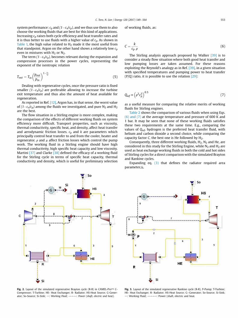
Fig. 2. Layout of the simulated regenerative Brayton cycle (R-B) in CAMEL-Pro™ C-Compressor; T-Turbine; HE- Heat Exchanger; R- Radiator; HS-Heat Source; G-Gener-ator; So-Source; Si-Sink; d: Working Fluid; -,-,-,-: Power (shaft, electric and heat).
of working fluids, as:
C ¼ kcp$r
(6)
The Stirling analysis approach proposed by Walker [39] is toconsider a steady flow situation where both good heat transfer andlow pumping losses are taken assumed. For these reasonsexploiting the Reynold's analogy as in Ref. [39], in a given situationwith specified temperatures and pumping power to heat transfer(P/Q) ratio, it is possible to use the relation [29]:
Qwff�r2c3p
�0:5(7)
as a useful measure for comparing the relative merits of workingfluids for Stirling engines.
Table 2 shows the comparison of various fluids when using Eqs.(6) and (7) at the average temperature and pressure of 600 K and1 bar. It may be seen that none of these working fluids satisfiesthese two requirements at the same time. E.g., comparing thevalues of Qwf, hydrogen is the preferred heat transfer fluid, withhelium and carbon dioxide a second choice, while comparing thecapacity factor C, the best one is He followed by H2.
Consequently, three different working fluids, H2, N2 and He, areconsidered in this study for the Stirling Engine, while N2 and H2 areused as heat exchange working fluids in both the cold and hot sidesof Stirling cycles for a direct comparisonwith the simulated Braytonand Rankine cycles.
Expanding eq. (3) that defines the radiator required areaparameter,j,
Fig. 3. Layout of the simulated regenerative Rankine cycle (R-R). P-Pump; T-Turbine;HE- Heat Exchanger; R- Radiator; HS-Heat Source; GeGenerator; So-Source; Si-Sink;d: Working Fluid; -,-,-,-,: Power (shaft, electric and heat.

Fig. 4. Layout of the simulated regenerative-reheated Brayton cycle (R-R-B). C-Compressor; T-Turbine; HE- Heat Exchanger; R- Radiator; HS-Heat Source; G-Generator: So-Source;Si-Sink; d: Working Fluid; -,-,-,-,: Power (shaft, electric and heat).
Fig. 5. Layout of the simulated regenerative e reheated Rankine cycle (R-R-R). P-Pump; T-Turbine; HE- Heat Exchanger; R- Radiator; HS-Heat Source; GeGenerator; So-Source; Si-Sink; d: Working Fluid; -,-,-,-,-: Power (shaft, electric and heat).
C. Toro, N. Lior / Energy 120 (2017) 549e564554
j ¼ WArad
¼ WQout=Urad
¼ WðQin �WÞ=Urad
¼ WW½ð1=hIÞ � 1�=Urad
¼ Urad½ð1=hIÞ � 1�
(8)
shows that jwould rise with the cycle energy efficiency h (becausemore efficient cycles reject less heat) and with the overall heattransfer coefficient of the radiator, Urad. The working fluids thusaffect j both in their effect on the cycle efficiency, hI, and in theireffect on Urad.

Fig. 6. Layout of the simulated regenerative-intercooled Brayton cycle (R-I-B). C-Compressor; T-Turbine; HE- Heat Exchanger; R- Radiator; HS-Heat Source; G-Generator; So-Source;Si-Sink; d: Working Fluid; -,-,-,-,-: Power (shaft, electric and heat).
C. Toro, N. Lior / Energy 120 (2017) 549e564 555
3. Cycle configurations
The layouts of the systems analyzed in this study are shown inFigs. 2e7.
The first step of this analysis has been the validation of theimplemented model by comparison of our simulation results forthe regenerative Rankine (Fig. 2) and Brayton (Fig. 3) cycles withthe simulations results from Ref. [12].
The assumption to fix the pL and TL of the Rankine cycle at0.75 bar and 84 K for Ar, and 0.15 bar and 64 K for N2, derives fromthe necessity of exploiting themaximum pressure and temperaturedrop up to the limit of the triple point (Ar: Ttp ¼ 83.8 K,ptp ¼ 0.69 bar; N2: Ttp ¼ 63.15 K, ptp ¼ 0.13 bar).
The turbine inlet temperature (TIT) selected was 1500 K, whichis well within the values of terrestrial gas turbine power plants (forexample, the Mitsubishi Heavy Industries gas-turbine system
Fig. 7. Layout of the simulated regenerated-reheated-intercooled (R-R-I-B) Brayton cycle. C-CSo-Source; Si-Sink; d: Working Fluid; -,-,-,-,-: Power (shaft, electric and heat.
reaches a TIT of 1773 K [40]). The present analysis focuses on highpower systems that use axial flow turbines, which typically easilyallow the use of blade cooling, in consideration of the fact that stateof the art Turbine blade cooling includes several methodologies andthat the specific peculiar space environment where the Turbineobject of the present study operates might strongly affect theimprovement in the cooling efficiency and furthermore, given thatmodern engines bled off for cooling and sealing purposes for nozzleguide vanes and turbine blades around 20% of the compressed air,we assumed that neglecting the impact of the cooling systemmightnot affect so much the performance evaluation. The use of N2 andAr at such temperatures has been proven to be suitable in otherstudies [41].
The results obtained with our CAMEL-Pro process simulator forthe same operative conditions of [12] are shown in Table 3 along-side those of [12], and are in excellent agreement, within 3%.
ompressor; T-Turbine; HE- Heat Exchanger; R- Radiator; HS-Heat Source; G-Generator;
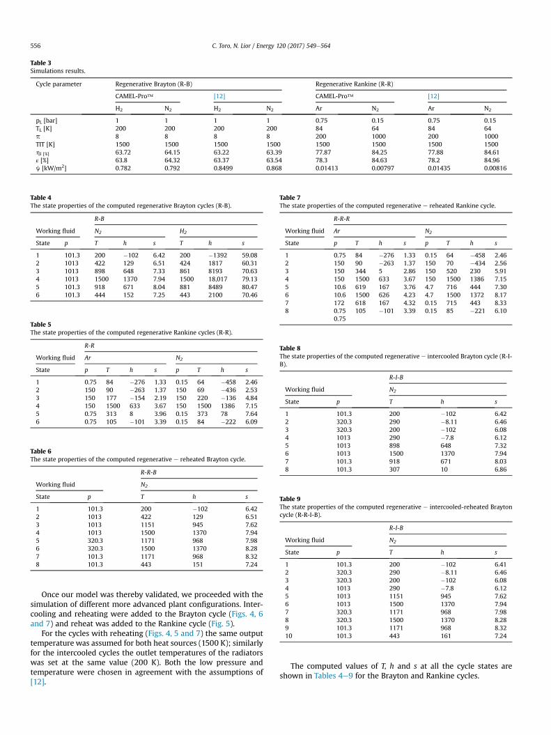
Table 3Simulations results.
Cycle parameter Regenerative Brayton (R-B) Regenerative Rankine (R-R)
CAMEL-Pro™ [12] CAMEL-Pro™ [12]
H2 N2 H2 N2 Ar N2 Ar N2
pL [bar] 1 1 1 1 0.75 0.15 0.75 0.15TL [K] 200 200 200 200 84 64 84 64p 8 8 8 8 200 1000 200 1000TIT [K] 1500 1500 1500 1500 1500 1500 1500 1500hI [%] 63.72 64.15 63.22 63.39 77.87 84.25 77.88 84.61ε [%] 63.8 64.32 63.37 63.54 78.3 84.63 78.2 84.96j [kW/m2] 0.782 0.792 0.8499 0.868 0.01413 0.00797 0.01435 0.00816
Table 4The state properties of the computed regenerative Brayton cycles (R-B).
R-B
Working fluid N2 H2
State p T h s T h s
1 101.3 200 �102 6.42 200 �1392 59.082 1013 422 129 6.51 424 1817 60.313 1013 898 648 7.33 861 8193 70.634 1013 1500 1370 7.94 1500 18,017 79.135 101.3 918 671 8.04 881 8489 80.476 101.3 444 152 7.25 443 2100 70.46
Table 5The state properties of the computed regenerative Rankine cycles (R-R).
R-R
Working fluid Ar N2
State p T h s p T h s
1 0.75 84 �276 1.33 0.15 64 �458 2.462 150 90 �263 1.37 150 69 �436 2.533 150 177 �154 2.19 150 220 �136 4.844 150 1500 633 3.67 150 1500 1386 7.155 0.75 313 8 3.96 0.15 373 78 7.646 0.75 105 �101 3.39 0.15 84 �222 6.09
Table 6The state properties of the computed regenerative e reheated Brayton cycle.
R-R-B
Working fluid N2
State p T h s
1 101.3 200 �102 6.422 1013 422 129 6.513 1013 1151 945 7.624 1013 1500 1370 7.945 320.3 1171 968 7.986 320.3 1500 1370 8.287 101.3 1171 968 8.328 101.3 443 151 7.24
Table 7The state properties of the computed regenerative e reheated Rankine cycle.
R-R-R
Working fluid Ar N2
State p T h s p T h s
1 0.75 84 �276 1.33 0.15 64 �458 2.462 150 90 �263 1.37 150 70 �434 2.563 150 344 5 2.86 150 520 230 5.914 150 1500 633 3.67 150 1500 1386 7.155 10.6 619 167 3.76 4.7 716 444 7.306 10.6 1500 626 4.23 4.7 1500 1372 8.177 172 618 167 4.32 0.15 715 443 8.338 0.75
0.75105 �101 3.39 0.15 85 �221 6.10
Table 8The state properties of the computed regenerative e intercooled Brayton cycle (R-I-B).
R-I-B
Working fluid N2
State p T h s
1 101.3 200 �102 6.422 320.3 290 �8.11 6.463 320.3 200 �102 6.084 1013 290 �7.8 6.125 1013 898 648 7.326 1013 1500 1370 7.947 101.3 918 671 8.038 101.3 307 10 6.86
Table 9The state properties of the computed regenerative e intercooled-reheated Braytoncycle (R-R-I-B).
R-I-B
Working fluid N2
State p T h s
1 101.3 200 �102 6.412 320.3 290 �8.11 6.463 320.3 200 �102 6.084 1013 290 �7.8 6.125 1013 1151 945 7.626 1013 1500 1370 7.947 320.3 1171 968 7.988 320.3 1500 1370 8.289 101.3 1171 968 8.3210 101.3 443 161 7.24
C. Toro, N. Lior / Energy 120 (2017) 549e564556
Once our model was thereby validated, we proceeded with thesimulation of different more advanced plant configurations. Inter-cooling and reheating were added to the Brayton cycle (Figs. 4, 6and 7) and reheat was added to the Rankine cycle (Fig. 5).
For the cycles with reheating (Figs. 4, 5 and 7) the same outputtemperature was assumed for both heat sources (1500 K); similarlyfor the intercooled cycles the outlet temperatures of the radiatorswas set at the same value (200 K). Both the low pressure andtemperature were chosen in agreement with the assumptions of[12].
The computed values of T, h and s at all the cycle states areshown in Tables 4e9 for the Brayton and Rankine cycles.
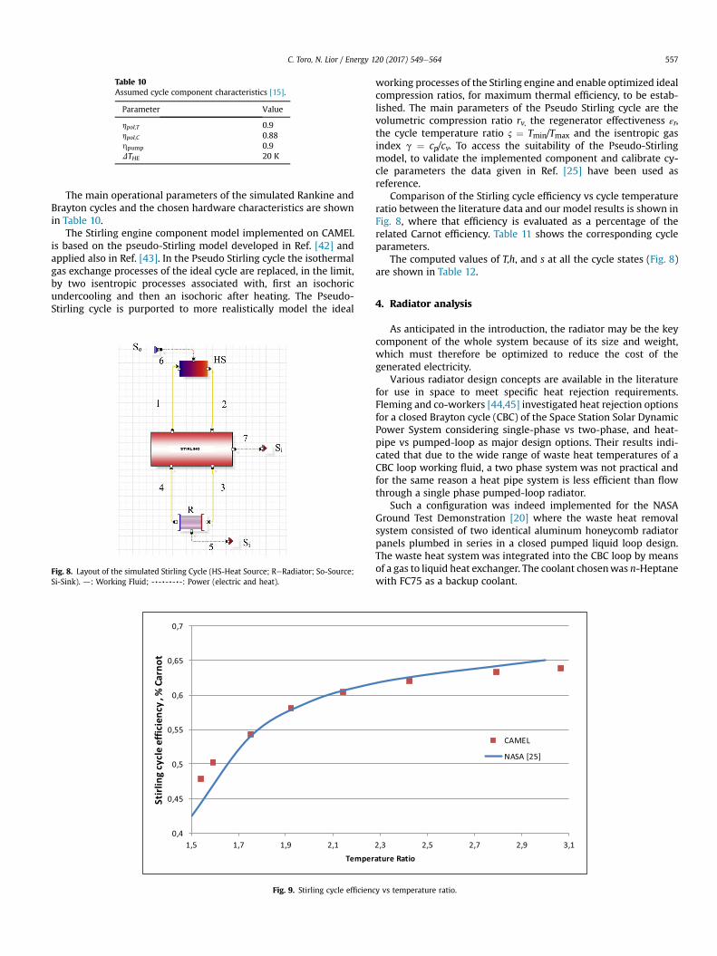
Table 10Assumed cycle component characteristics [15].
Parameter Value
hpol,T 0.9hpol,C 0.88hpump 0.9DTHE 20 K
C. Toro, N. Lior / Energy 120 (2017) 549e564 557
The main operational parameters of the simulated Rankine andBrayton cycles and the chosen hardware characteristics are shownin Table 10.
The Stirling engine component model implemented on CAMELis based on the pseudo-Stirling model developed in Ref. [42] andapplied also in Ref. [43]. In the Pseudo Stirling cycle the isothermalgas exchange processes of the ideal cycle are replaced, in the limit,by two isentropic processes associated with, first an isochoricundercooling and then an isochoric after heating. The Pseudo-Stirling cycle is purported to more realistically model the ideal
Fig. 8. Layout of the simulated Stirling Cycle (HS-Heat Source; ReRadiator; So-Source;Si-Sink). d: Working Fluid; -,-,-,-,-: Power (electric and heat).
Fig. 9. Stirling cycle efficienc
working processes of the Stirling engine and enable optimized idealcompression ratios, for maximum thermal efficiency, to be estab-lished. The main parameters of the Pseudo Stirling cycle are thevolumetric compression ratio rv, the regenerator effectiveness εr,the cycle temperature ratio 2 ¼ Tmin/Tmax and the isentropic gasindex g ¼ cp/cv. To access the suitability of the Pseudo-Stirlingmodel, to validate the implemented component and calibrate cy-cle parameters the data given in Ref. [25] have been used asreference.
Comparison of the Stirling cycle efficiency vs cycle temperatureratio between the literature data and our model results is shown inFig. 8, where that efficiency is evaluated as a percentage of therelated Carnot efficiency. Table 11 shows the corresponding cycleparameters.
The computed values of T,h, and s at all the cycle states (Fig. 8)are shown in Table 12.
4. Radiator analysis
As anticipated in the introduction, the radiator may be the keycomponent of the whole system because of its size and weight,which must therefore be optimized to reduce the cost of thegenerated electricity.
Various radiator design concepts are available in the literaturefor use in space to meet specific heat rejection requirements.Fleming and co-workers [44,45] investigated heat rejection optionsfor a closed Brayton cycle (CBC) of the Space Station Solar DynamicPower System considering single-phase vs two-phase, and heat-pipe vs pumped-loop as major design options. Their results indi-cated that due to the wide range of waste heat temperatures of aCBC loop working fluid, a two phase system was not practical andfor the same reason a heat pipe system is less efficient than flowthrough a single phase pumped-loop radiator.
Such a configuration was indeed implemented for the NASAGround Test Demonstration [20] where the waste heat removalsystem consisted of two identical aluminum honeycomb radiatorpanels plumbed in series in a closed pumped liquid loop design.The waste heat system was integrated into the CBC loop by meansof a gas to liquid heat exchanger. The coolant chosenwas n-Heptanewith FC75 as a backup coolant.
y vs temperature ratio.
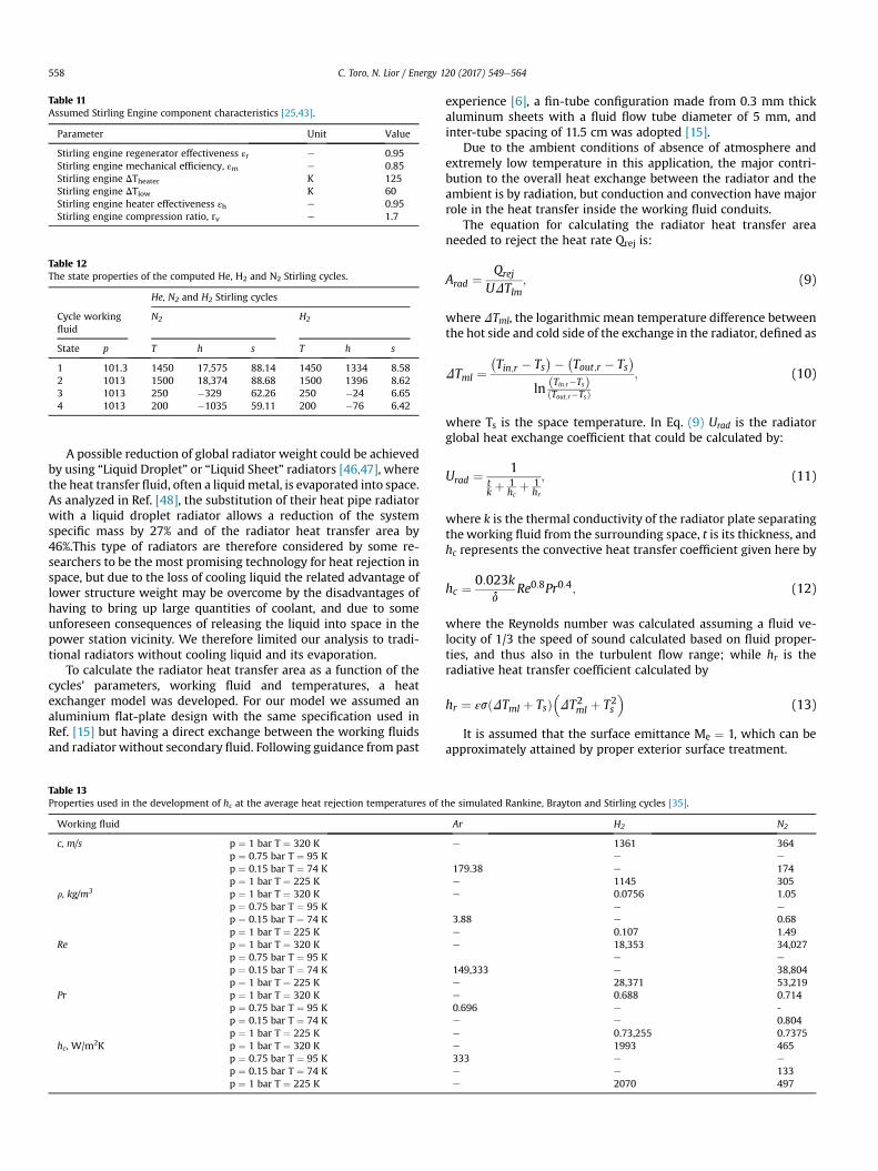
Table 11Assumed Stirling Engine component characteristics [25,43].
Parameter Unit Value
Stirling engine regenerator effectiveness εr e 0.95Stirling engine mechanical efficiency, εm e 0.85Stirling engine DTheater K 125Stirling engine DTlow K 60Stirling engine heater effectiveness εh e 0.95Stirling engine compression ratio, rv e 1.7
Table 12The state properties of the computed He, H2 and N2 Stirling cycles.
He, N2 and H2 Stirling cycles
Cycle workingfluid
N2 H2
State p T h s T h s
1 101.3 1450 17,575 88.14 1450 1334 8.582 1013 1500 18,374 88.68 1500 1396 8.623 1013 250 �329 62.26 250 �24 6.654 1013 200 �1035 59.11 200 �76 6.42
C. Toro, N. Lior / Energy 120 (2017) 549e564558
A possible reduction of global radiator weight could be achievedby using “Liquid Droplet” or “Liquid Sheet” radiators [46,47], wherethe heat transfer fluid, often a liquidmetal, is evaporated into space.As analyzed in Ref. [48], the substitution of their heat pipe radiatorwith a liquid droplet radiator allows a reduction of the systemspecific mass by 27% and of the radiator heat transfer area by46%.This type of radiators are therefore considered by some re-searchers to be the most promising technology for heat rejection inspace, but due to the loss of cooling liquid the related advantage oflower structure weight may be overcome by the disadvantages ofhaving to bring up large quantities of coolant, and due to someunforeseen consequences of releasing the liquid into space in thepower station vicinity. We therefore limited our analysis to tradi-tional radiators without cooling liquid and its evaporation.
To calculate the radiator heat transfer area as a function of thecycles' parameters, working fluid and temperatures, a heatexchanger model was developed. For our model we assumed analuminium flat-plate design with the same specification used inRef. [15] but having a direct exchange between the working fluidsand radiator without secondary fluid. Following guidance from past
Table 13Properties used in the development of hc at the average heat rejection temperatures of t
Working fluid
c, m/s p ¼ 1 bar T ¼ 320 Kp ¼ 0.75 bar T ¼ 95 Kp ¼ 0.15 bar T ¼ 74 Kp ¼ 1 bar T ¼ 225 K
r, kg/m3 p ¼ 1 bar T ¼ 320 Kp ¼ 0.75 bar T ¼ 95 Kp ¼ 0.15 bar T ¼ 74 Kp ¼ 1 bar T ¼ 225 K
Re p ¼ 1 bar T ¼ 320 Kp ¼ 0.75 bar T ¼ 95 Kp ¼ 0.15 bar T ¼ 74 Kp ¼ 1 bar T ¼ 225 K
Pr p ¼ 1 bar T ¼ 320 Kp ¼ 0.75 bar T ¼ 95 Kp ¼ 0.15 bar T ¼ 74 Kp ¼ 1 bar T ¼ 225 K
hc, W/m2K p ¼ 1 bar T ¼ 320 Kp ¼ 0.75 bar T ¼ 95 Kp ¼ 0.15 bar T ¼ 74 Kp ¼ 1 bar T ¼ 225 K
experience [6], a fin-tube configuration made from 0.3 mm thickaluminum sheets with a fluid flow tube diameter of 5 mm, andinter-tube spacing of 11.5 cm was adopted [15].
Due to the ambient conditions of absence of atmosphere andextremely low temperature in this application, the major contri-bution to the overall heat exchange between the radiator and theambient is by radiation, but conduction and convection have majorrole in the heat transfer inside the working fluid conduits.
The equation for calculating the radiator heat transfer areaneeded to reject the heat rate Qrej is:
Arad ¼ Qrej
UDTlm; (9)
where DTml, the logarithmic mean temperature difference betweenthe hot side and cold side of the exchange in the radiator, defined as
DTml ¼�Tin;r � Ts
�� �Tout;r � Ts
�ln ðTin;r�TsÞ
ðTout;r�TsÞ; (10)
where Ts is the space temperature. In Eq. (9) Urad is the radiatorglobal heat exchange coefficient that could be calculated by:
Urad ¼ 1tk þ 1
hcþ 1
hr
; (11)
where k is the thermal conductivity of the radiator plate separatingthe working fluid from the surrounding space, t is its thickness, andhc represents the convective heat transfer coefficient given here by
hc ¼ 0:023kd
Re0:8Pr0:4; (12)
where the Reynolds number was calculated assuming a fluid ve-locity of 1/3 the speed of sound calculated based on fluid proper-ties, and thus also in the turbulent flow range; while hr is theradiative heat transfer coefficient calculated by
hr ¼ εsðDTml þ TsÞ�DT2ml þ T2s
�(13)
It is assumed that the surface emittance Me ¼ 1, which can beapproximately attained by proper exterior surface treatment.
he simulated Rankine, Brayton and Stirling cycles [35].
Ar H2 N2
e 1361 364e e
179.38 e 174e 1145 305e 0.0756 1.05
e e
3.88 e 0.68e 0.107 1.49e 18,353 34,027
e e
149,333 e 38,804e 28,371 53,219e 0.688 0.7140.696 e -e e 0.804e 0.73,255 0.7375e 1993 465333 e e
e e 133e 2070 497
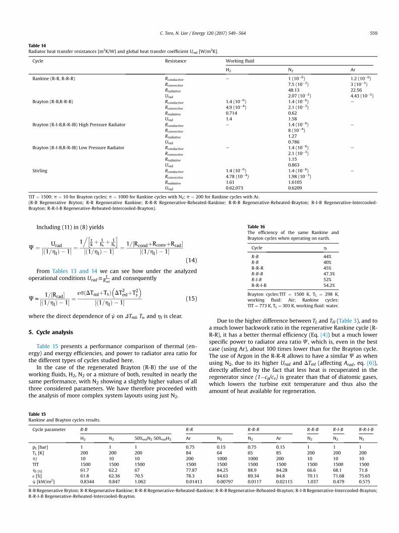
Table 14Radiator heat transfer resistances [m2K/W] and global heat transfer coefficient Urad [W/m2K].
Cycle Resistance Working fluid
H2 N2 Ar
Rankine (R-R, R-R-R) Rconductive e 1 (10�6) 1.2 (10�6)Rconvective 7.5 (10�3) 3 (10�3)Rradiative 48.13 22.56Urad 2.07 (10�2) 4.43 (10�2)
Brayton (R-B,R-R-B) Rconductive 1.4 (10�6) 1.4 (10�6) e
Rconvective 4.9 (10�4) 2.1 (10�3)Rradiative 0.714 0.62Urad 1.4 1.58
Brayton (R-I-B,R-R-IB) High Pressure Radiator Rconductive e 1.4 (10�6) e
Rconvective 8 (10�4)Rradiative 1.27Urad 0.786
Brayton (R-I-B,R-R-IB) Low Pressure Radiator Rconductive e 1.4 (10�6) e
Rconvective 2.1 (10�3)Rradiative 1.15Urad 0.863
Stirling Rconductive 1.4 (10�6) 1.4 (10�6) e
Rconvective 4.78 (10�4) 1.98 (10�3)Rradiative 1.61 1.6105Urad 0.62,073 0.6209
TIT ¼ 1500; p ¼ 10 for Brayton cycles; p ¼ 1000 for Rankine cycles with N2; p ¼ 200 for Rankine cycles with Ar.(R-B Regenerative Bryton; R-R Regenerative Rankine; R-R-R Regenerative-Reheated-Rankine; R-R-B Regenerative-Reheated-Brayton; R-I-B Regenerative-Intercooled-Brayton; R-R-I-B Regenerative-Reheated-Intercooled-Brayton).
Table 16The efficiency of the same Rankine andBrayton cycles when operating on earth.
Cycle hI
R-B 44%R-R 40%R-R-R 45%R-R-B 47.3%R-I-B 52%R-R-I-B 54.2%
Brayton cycles:TIT ¼ 1500 K, TL ¼ 298 K,working fluid: Air; Rankine cycles:TIT ¼ 773 K, TL ¼ 303 K, working fluid: water.
C. Toro, N. Lior / Energy 120 (2017) 549e564 559
Including (11) in (8) yields
J ¼ Urad½ð1=hIÞ � 1� ¼
1.h
tk þ 1
hcþ 1
hr
i½ð1=hIÞ � 1� ¼ 1=½RcondþRconvþRrad�
½ð1=hIÞ � 1�(14)
From Tables 13 and 14 we can see how under the analyzedoperational conditions Urady
1Rrad
and consequently
Jz1=½Rrad�
½ð1=hIÞ � 1� ¼εsðDTmlþTsÞ
�DT2mlþT2s
�½ð1=hIÞ � 1� (15)
where the direct dependence of j on DTml, Ts, and hI is clear.
5. Cycle analysis
Table 15 presents a performance comparison of thermal (en-ergy) and exergy efficiencies, and power to radiator area ratio forthe different types of cycles studied here.
In the case of the regenerated Brayton (R-B) the use of theworking fluids, H2, N2 or a mixture of both, resulted in nearly thesame performance, with N2 showing a slightly higher values of allthree considered parameters. We have therefore proceeded withthe analysis of more complex system layouts using just N2.
Table 15Rankine and Brayton cycles results.
Cycle parameter R-B R-R
H2 N2 50%volN2 50%volH2 Ar
pL [bar] 1 1 1 0.75TL [K] 200 200 200 84p/ 10 10 10 200TIT 1500 1500 1500 1500hI [%] 61.7 62.2 67 77.87ε [%] 61.8 62.36 70.5 78.3j [kW/m2] 0.8344 0.847 1.062 0.01413
R-B Regenerative Bryton; R-R Regenerative Rankine; R-R-R Regenerative-Reheated-RankiR-R-I-B Regenerative-Reheated-Intercooled-Brayton.
Due to the higher difference between TL and TH (Table 3), and toa much lower backwork ratio in the regenerative Rankine cycle (R-R-R), it has a better thermal efficiency (Eq. (4)) but a much lowerspecific power to radiator area ratio J, which is, even in the bestcase (using Ar), about 100 times lower than for the Brayton cycle.The use of Argon in the R-R-R allows to have a similar J as whenusing N2, due to its higher Urad and DTml (affecting Arad, eq. (6)),directly affected by the fact that less heat is recuperated in theregenerator since (1�cp/cv) is greater than that of diatomic gases,which lowers the turbine exit temperature and thus also theamount of heat available for regeneration.
R-R-R R-R-B R-I-B R-R-I-B
N2 N2 Ar N2 N2 N2
0.15 0.75 0.15 1 1 164 65 85 200 200 2001000 1000 200 10 10 101500 1500 1500 1500 1500 150084.25 88.9 84.28 66.6 68.1 71.884.63 89.34 84.8 70.11 71.68 75.650.00797 0.0117 0.02115 1.037 0.479 0.575
ne; R-R-B Regenerative-Reheated-Brayton; R-I-B Regenerative-Intercooled-Brayton;
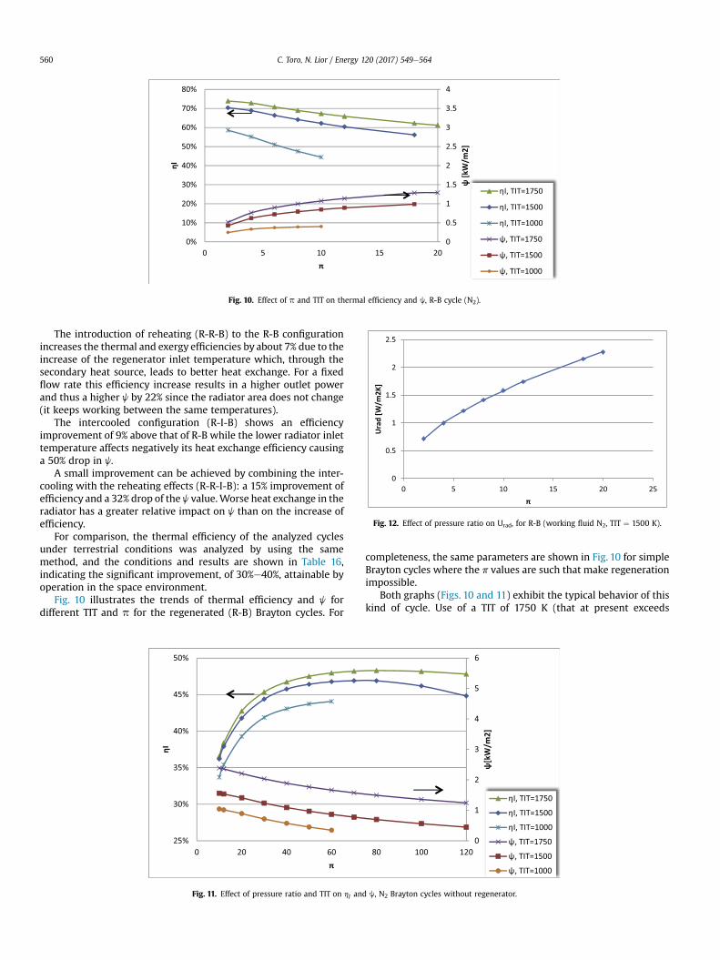
Fig. 10. Effect of p and TIT on thermal efficiency and j, R-B cycle (N2).
Fig. 12. Effect of pressure ratio on Urad, for R-B (working fluid N2, TIT ¼ 1500 K).
C. Toro, N. Lior / Energy 120 (2017) 549e564560
The introduction of reheating (R-R-B) to the R-B configurationincreases the thermal and exergy efficiencies by about 7% due to theincrease of the regenerator inlet temperature which, through thesecondary heat source, leads to better heat exchange. For a fixedflow rate this efficiency increase results in a higher outlet powerand thus a higher j by 22% since the radiator area does not change(it keeps working between the same temperatures).
The intercooled configuration (R-I-B) shows an efficiencyimprovement of 9% above that of R-B while the lower radiator inlettemperature affects negatively its heat exchange efficiency causinga 50% drop in j.
A small improvement can be achieved by combining the inter-cooling with the reheating effects (R-R-I-B): a 15% improvement ofefficiency and a 32% drop of the j value.Worse heat exchange in theradiator has a greater relative impact on j than on the increase ofefficiency.
For comparison, the thermal efficiency of the analyzed cyclesunder terrestrial conditions was analyzed by using the samemethod, and the conditions and results are shown in Table 16,indicating the significant improvement, of 30%e40%, attainable byoperation in the space environment.
Fig. 10 illustrates the trends of thermal efficiency and j fordifferent TIT and p for the regenerated (R-B) Brayton cycles. For
Fig. 11. Effect of pressure ratio and TIT on hI an
completeness, the same parameters are shown in Fig. 10 for simpleBrayton cycles where the p values are such that make regenerationimpossible.
Both graphs (Figs. 10 and 11) exhibit the typical behavior of thiskind of cycle. Use of a TIT of 1750 K (that at present exceeds
d j, N2 Brayton cycles without regenerator.

Fig. 13. Comparison of thermal efficiency of Brayton cycles with different configurations (Working fluid: N2; TIT ¼ 1500 K).
Fig. 14. Comparison of j of Brayton cycles with different layouts (Working fluid: N2;TIT ¼ 1500 K).
Fig. 15. Effect of p and TIT on J for the R-R-R cycle.
Fig. 16. Effect of p and TIT on hI for the R-R-R cycle.
C. Toro, N. Lior / Energy 120 (2017) 549e564 561
convectional practice values but could represent future technologydevelopments) shows that efficiencies above 70% could be reachedwith use of the regenerated Brayton cycle.
hI and j are inversely dependent on the system pressure ratio(p) in both regenerated and not regenerated Brayton cycle for allturbine inlet temperatures.
The physical explanation of such a behavior is deducible from Eq(15): the increase of p corresponds to an increase of DTml in theradiator and this has a stronger impact on j (Urad is proportional toDTml
4 ) than on the decrease of hI. As an example of that, thedependence of Urad on p for the R-B cycle is shown in Fig. 12.
Figs. 13 and 14 show the effect of the cycle configuration on itsthermal efficiency and j as a function of p. Apart from the above-described dependence of hI and j on the different layouts, it isinteresting to note the difference between the hI slopes in theconsidered configurations.
It is in particular evident how the introduction of reheating andintercooling allows to increase the regeneration efficiency byreducing the compressor outlet temperature and increasing theturbine outlet temperature, and so diminishing the negative impactof p on the overall efficiency.
Figs. 15 and 16 show the effect of p and TIT on hI and j for the R-R-R cycle. The thermal efficiency and j of the cycle increasesignificantly, as expected, with increasing TIT, while the effect of pis nearly negligible.
Table 17 presents a performance comparison of the thermal andexergy efficiency, hI and ε, respectively, and power to radiator arearatio, j, for the different types of Stirling space power cyclesstudied here.
The results show that the efficiencies' and j values are the same

Table 17Stirling cycles results.
Cycle working fluid H2 N2
Stirling working fluid H2 N2 He H2 N2 He
pL [bar] 1 1 1 1 1 1TL [K] 200 200 200 200 200 200rv 2.15 2.3 1.55 2.15 2.3 1.55TH 1500 1500 1500 1500 1500 1500mwf,hs [kg/s] 0.060 0.060 0.060 0.78 0.78 0.78mwf,cs [kg/s] 0.011 0.011 0.011 0.16 0.16 0.16hStirling [%] 62.2 62.2 62.2 62.2 62.2 62.2hI [%] 52.8 52.8 52.8 52.8 52.8 52.8ε [%] 64.8 64,8 63.3 64.8 64,8 63.3j [kW/m2] 0.483 0.483 0.483 0.483 0.483 0.483
C. Toro, N. Lior / Energy 120 (2017) 549e564562
throughout, due to the choice of optimized rv values [42] that, oncefixing the temperature ratio, reaches maximal efficiencies inde-pendently of the choice of working fluids. The use of the workingfluids H2 and N2 in the cycle resulted in nearly the same perfor-mance and does not affect the radiator area because the contribu-tion of the radiative exchange is much higher than the convectiveone (Table 11). We have therefore proceeded with the analysisconsidering only H2 while H2, N2 as cycle working fluid and He forthe Stirling engine has been included. Also for the Stirling cycle, thesimulated terrestrial cycle indicate the significant improvement of
Fig. 17. Stirling cycle thermal efficiency comparison for differ
Fig. 18. Stirling cycle j comparison for different wor
40%, attainable by operation in the space environment.The variation of hI and j with rv and the gas index is shown in
Figs. 17 and 18 for a regenerator effectiveness of 0.95 and a tem-perature ratio of 0.2. Only compression ratios up to 5:1 are shownsince values about this figures are unrealistic for Stirling engines.
An improvement of thermal and exergy efficiency and of j canbe reached raising the cycle higher temperature (TH, i.e. T2 in Fig. 9)as shown in Fig. 19. The increase of TH/TL has a positive effect onStirling efficiency and thus on the cycle performance.
Stirling cycles' efficiencies are lower than those obtained by theBrayton and Rankine cycles for the same cycle TH but with values ofj equal to about half of those obtained by Brayton cycles but muchhigher than those obtained by the Rankine cycles.
It is interesting to compare Brayton and Stirling efficiencies andj as functions of the cycle minimal (heat sink) temperature. Fig. 20shows the effect of TL on Brayton and Stirling cycle efficienciesexpressed as a percentage of the Carnot efficiency calculated for thesame TH and TL. While the Brayton cycle efficiency is substantiallyreduced by increasing TL, the Stirling cycle efficiency shows a smallreduction, keeping it higher than 60% of the Carnot efficiency. Ingeneral, lower heat sink temperatures result in larger radiators(Fig. 21) due to the lower rejection temperatures, but smaller heatsource requirement (Fig. 22). Higher heat sink temperatures lowerthe area of the needed radiators, but raise heat source requirementdue to the lower efficiency. In the Brayton cycle the substantial
ent working fluids (TH ¼ 1500 K, TL ¼ 200 K,εr ¼ 0.85).
king fluids (TH ¼ 1500 K, TL ¼ 200 K, εr ¼ 0.85).
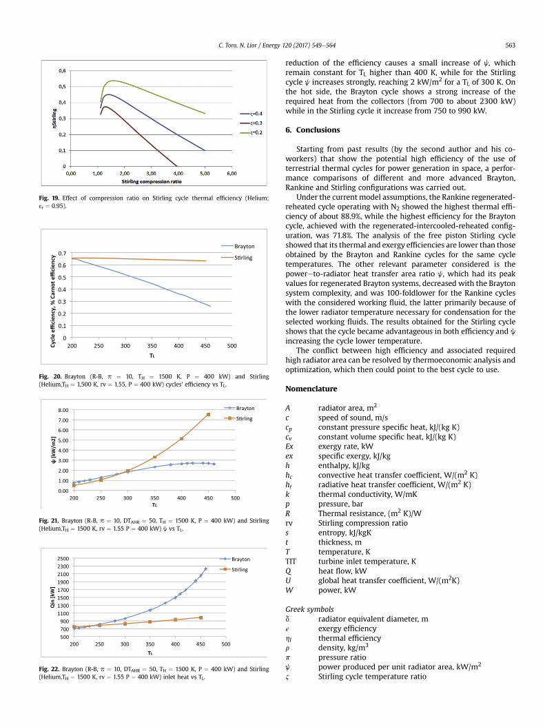
Fig. 22. Brayton (R-B, p ¼ 10, DTAHR ¼ 50, TH ¼ 1500 K, P ¼ 400 kW) and Stirling(Helium,TH ¼ 1500 K, rv ¼ 1.55 P ¼ 400 kW) inlet heat vs TL.
Fig. 21. Brayton (R-B, p ¼ 10, DTAHR ¼ 50, TH ¼ 1500 K, P ¼ 400 kW) and Stirling(Helium,TH ¼ 1500 K, rv ¼ 1.55 P ¼ 400 kW) j vs TL.
Fig. 19. Effect of compression ratio on Stirling cycle thermal efficiency (Helium;εr ¼ 0.95).
Fig. 20. Brayton (R-B, p ¼ 10, TH ¼ 1500 K, P ¼ 400 kW) and Stirling(Helium,TH ¼ 1,500 K, rv ¼ 1.55, P ¼ 400 kW) cycles' efficiency vs TL.
C. Toro, N. Lior / Energy 120 (2017) 549e564 563
reduction of the efficiency causes a small increase of j, whichremain constant for TL higher than 400 K, while for the Stirlingcycle j increases strongly, reaching 2 kW/m2 for a TL of 300 K. Onthe hot side, the Brayton cycle shows a strong increase of therequired heat from the collectors (from 700 to about 2300 kW)while in the Stirling cycle it increase from 750 to 990 kW.
6. Conclusions
Starting from past results (by the second author and his co-workers) that show the potential high efficiency of the use ofterrestrial thermal cycles for power generation in space, a perfor-mance comparisons of different and more advanced Brayton,Rankine and Stirling configurations was carried out.
Under the current model assumptions, the Rankine regenerated-reheated cycle operating with N2 showed the highest thermal effi-ciency of about 88.9%, while the highest efficiency for the Braytoncycle, achieved with the regenerated-intercooled-reheated config-uration, was 71.8%. The analysis of the free piston Stirling cycleshowed that its thermal and exergy efficiencies are lower than thoseobtained by the Brayton and Rankine cycles for the same cycletemperatures. The other relevant parameter considered is thepowereto-radiator heat transfer area ratio j, which had its peakvalues for regenerated Brayton systems, decreased with the Braytonsystem complexity, and was 100-foldlower for the Rankine cycleswith the considered working fluid, the latter primarily because ofthe lower radiator temperature necessary for condensation for theselected working fluids. The results obtained for the Stirling cycleshows that the cycle became advantageous in both efficiency and jincreasing the cycle lower temperature.
The conflict between high efficiency and associated requiredhigh radiator area can be resolved by thermoeconomic analysis andoptimization, which then could point to the best cycle to use.
Nomenclature
A radiator area, m2
c speed of sound, m/scp constant pressure specific heat, kJ/(kg K)cv constant volume specific heat, kJ/(kg K)Ex exergy rate, kWex specific exergy, kJ/kgh enthalpy, kJ/kghc convective heat transfer coefficient, W/(m2 K)hr radiative heat transfer coefficient, W/(m2 K)k thermal conductivity, W/mKp pressure, barR Thermal resistance, (m2 K)/Wrv Stirling compression ratios entropy, kJ/kgKt thickness, mT temperature, KTIT turbine inlet temperature, KQ heat flow, kWU global heat transfer coefficient, W/(m2K)W power, kW
Greek symbolsd radiator equivalent diameter, mε exergy efficiencyhI thermal efficiencyr density, kg/m3
p pressure ratioj power produced per unit radiator area, kW/m2
2 Stirling cycle temperature ratio
C. Toro, N. Lior / Energy 120 (2017) 549e564564
References
[1] Mankins J. Space solar power: a major new energy option? J Aerosp Eng2001;14:38e45.
[2] Lior N. Power from space. Energy Convers Manag 2001;42:1769e805.[3] Klann JL. Steady-state analysis of a Brayton space-power system. National
Aeronautics and Space Administration, Lewis Research Center; 1970.[4] Mason LS. A solar dynamic power option for space solar power. Cleveland,
Ohio: Glenn Research Center; 1999.[5] Dhar M. Stirling space engine program, Vols. 1 & 2; 1997. Final Report.[6] Lior N. The ECOS 2009 World Energy Panel: an introduction to the Panel and
to the present (2009) situation in sustainable energy development. Energy2011;36:3620e8.
[7] Glaser PE. Power from the sun: its future. Science 1968;162:857e61.[8] Glaser PE. An overview of the solar power satellite option. IEEE Trans Microw
Theory Tech 1992;40:1230e8.[9] Criswell DR, Thompson RG. Wireless power transmission data envelopment
analysis of space and terrestrially-based large scale commercial power sys-tems for earth: a prototype analysis of their relative economic advantages. SolEnergy 1996;56:119e31.
[10] Brown WC. Wireless power transmission the history of wireless powertransmission. Sol Energy 1996;56:3e21.
[11] Woodcock GR. Solar satellites e space key to our power future. AstronautAeronaut 1977;15:30e43.
[12] Tarlecki J, Lior N, Zhang N. Analysis of thermal cycles and working fluids forpower generation in space. Energy Convers Manag 2007;48:2864e78.
[13] Zidan�sek A, Ambro�zi�c M, Milfelner M, Blinc R, Lior N. Solar orbital power:sustainability analysis. Energy 2011;36:1986e95.
[14] Wu Y-T, Ren J-X, Guo Z-Y, Liang X-G. Optimal analysis of a space solar dy-namic power system. Sol Energy 2003;74:205e15.
[15] S.o.S.D.P.S. Branch. In: O. Lewis Research Center Cleveland, editor. Solar dy-namic power system development for space station freedom; 1993.
[16] Tsujikawa Y. Optimum heat rejection in Brayton cycle solar dynamic powersystem. Clean and Safe energy forever. Proc Int Sol Energy Soc Kobe City, Jpn1990;1989(2):1358e62.
[17] Glassman A, Stewart W. A look at the thermodynamic characteristics ofBrayton cycles for space power Summer Meeting. American Institute ofAeronautics and Astronautics; 1963.
[18] Mackay DB. Powerplant heat cycles for space vehicles. Inst Aero Sci; 1959.[19] Davis JE. Design and fabrication of the Brayton rotating unit. Lewis Research
Center, NASA; 1972.[20] Mason LS, Kudija CT. Solar dynamic ground test demonstration ( SD GTD)
system test plans. Joint Solar Engineering Conference. ASME; 1994.[21] Shaltens RK, Mason LS. 800 Hours of operational experience from a 2kWe
solar dynamic system. Cleveland, Ohio: NASA Lewis Research Center; 1999.[22] Mason LS, Schreiber JG. A historical review of Brayton and Stirling power
conversion technologies for space applications space nuclear conference.2007.
[23] Agazzani A, Massardo A. Advanced solar dynamic space power systems, Part I:efficiency and surface optimization. J Sol Energy Eng 1995;117:265e73.
[24] Agazzani A, Massardo A. Advanced solar dynamic space power systems, PartII: detailed design and specific parameters optimization. J Sol Energy Eng1995;117:274e81.
[25] Slaby JG. Overview of free-piston stirling engine technology for space powerapplication. In: Solar energy conference, Honolulu, Hawaii, USA; 1987.
[26] Mason LS. A comparison of fission power system options for lunar and marssurface applications. In: Space technology and applications internationalforum (STAIFe2006), Albuquerque, New Mexico, USA; 2006.
[27] Dhar M. Stirling space power program, Vols. 1 & 2; 1997. Final Report.[28] Wood JG, Neill L. Advanced 35 W free-piston stirling engine for space power
applications. In: Space technology and applications international forum-eSTAIF 2003; 2003.
[29] Toro C, Lior N. Analysis and comparison of different thermal cycles for powergeneration in space. In: Proceedings of the 27th international conference onefficiency, cost, optimization, simulation and environmental impact of energysystems, ECOS 2014; 2014.
[30] Amati V, Coccia A, Sciubba E, Toro C. CAMEL-pro users manual, rev, vol. 4;2010. www.turbomachinery.it.
[31] Universit�a di Roma. La Sapienza. CAMEL-pro users manual, v.4. 2008. www.turbomachinery.it.
[32] Amati V, Sciubba E, Toro C. Exergy analysis of a solid oxide fuel cell-gas tur-bine hybrid power plant. 2009. p. 721e31.
[33] Sciubba E, Toro C. Modeling and simulation of a hybrid PV/thermal collector.In: ECOS 2011, Novi Sad, Serbia; 2011.
[34] Colonna P, van der Stelt T. FluidProp: a program for the estimation of thermophysical properties of fluids. The Netherlands: Energy Technology Section,Delft University of Technology; 2004. http://wwwFluidPropcom.
[35] Lemmon EW, Huber ML, McLinden MO. NIST standard reference database 23:reference fluid thermodynamic and transport properties-REFPROP, Version9.1. 2013.
[36] Shaltens RK, Mason LS. Early results from solar dynamic space power systemtesting. J Propuls Power 1996;12:852e8.
[37] Martini WR. Stirling engine design manual. 1983.[38] Clarke RG, Taylor DR. Experiences in the commissioning of a prototype 20kW
helium charged Stirling engine. In: Seventeenth intersociety energy conver-sion engineering conference; 1982. p. 1796e800.
[39] Walker G. Stirling cycle machines. Oxford: Clarendon Press; 1973.[40] Yamamoto T, Furuhata T, Arai N, Lior N. Analysis of a high-efficiency low-
emissions "chemical gas turbine" system. J Propuls Power 2002;18:432e9.[41] Ulizar I, Pilidis P. Design of a semiclosed-cycle gas turbine with carbon
dioxideeargon as working fluid. J Eng Gas Turbines Power 1998;120:330e5.[42] Reader GT. The pseudo stirling cycle e a suitable performance criterion. In:
13th Intersociety Energy Conversion Engineering Conference, San Diego;1978. p. 1763e70.
[43] Rokni M. Thermodynamic analysis of SOFC (solid oxide fuel cell)eStirlinghybrid plants using alternative fuels. Energy 2013;61:87e97.
[44] Fleming M, Hoehn F. Radiator selection for space station solar dynamic powersystems. Energy e New Front 1987;1:208e13.
[45] Fleming M, Flores RR. Solar dynamic radiator design development. In: Jointsolar engineering conference ASME 1994, San Francisco, California; 1994.
[46] Tagliafico LA, Fossa M. Lightweight radiator optimization for heat rejection inspace. Heat Mass Transf 1997;32:239e44.
[47] Mattick AT, Hertzberg A. Liquid droplet radiators for heat rejection in space.J Energy 1981;5:387e93.
[48] Massardo AF, Tagliafico LA, Fossa M, Agazzani A. Solar space power systemoptimization with ultralight radiator. J Propuls Power 1997;13:560e4.
Related Documents