ISSN (e): 2250 – 3005 || Vol, 04 || Issue, 9 || September – 2014 || International Journal of Computational Engineering Research (IJCER) www.ijceronline.com Open Access Journal Page 12 Analysis About Losses of Centrifugal Pump by Matlab 1 Ravi Shastri, 2 Anjani Kumar Singh, 3 Manish Kumar Singh 1 Asst. Prof. Cambridge Institute of Technology, Tatisilway, Ranchi, Jharkhand, India 2 Ph.D. Scholar, Materials and metallurgical Engineering National Institute of Foundry and Forge Technology, Hatia, Ranchi, Jharkhand, India 3 M.Tech Scholar, Materials Science and Engineering, National Institute of Foundry and Forge Technology, Hatia, Ranchi, Jharkhand, India I. INTRODUCTION Pumps are used in a wide range of industrial and residential applications. Pumping equipment is extremely diverse, varying in type, size, and materials of construction. There have been significant new developments in the area of pumping equipment. They are used to transfer liquids from low-pressure to high pressure in this system, the liquid would move in the opposite direction because of the pressure difference.Centrifugal pumps are widely used for irrigation, water supply plants, stream power plants, sewage, oil refineries, chemical plants, hydraulic power service, food processing factories and mines. Moreover, they are also used extensively in the chemical industry because of their suitability in practically any service and are mostly used in many applications such as water pumping project, domestic water raising, industrial waste water removal, raising water from tube wells to the fields. A centrifugal pump delivers useful energy to the fluid on pump-agelargely through velocity changes that occur as this fluid flows through the impeller and the associated fixed passage ways of the pump. It is converting of mechanical energy to hydraulic energy of the handling fluid to get it to a required place or height by the centrifugal force of the impeller blade. The input power of centrifugal pump is the mechanical energy and such as electrical motor of the drive shaft driven by the prime mover or small engine. The output energy is hydraulic energy of the fluid being raised or carried. In a centrifugal pump, the liquid is forced by atmospheric or other pressure into a set of rotating vanes. A centrifugal pump consists of a set of rotation vanes enclosed within a housing or casing that is used to impart energy to a fluid through centrifugal force [1-3]. ABSTRACT : Design aids available today might have helped the pump designers to bring about theoretically the most efficient pumps, but the production technology and quality control during manufacture has not kept pace with such achievements in realizing the goals of developing energy efficient pumps. Pump designers often face the problem of selecting and optimizing a number of independent geometrical parameters whilst aiming at the derived efficiency from the pump. The only option is to approximate the theoretical design with experimental findings iteratively until the end result is achieved. It is found that about half of pumps were not performing efficiently, either because the wrong pump had been chosen for the job or because the pump was worn. If the pump is not doing its job, this can increase pumping costs and reduce productivity. To certain costs, use need to monitor energy usage regularly and repair and maintain the pump to operate efficiently. The aim of careful pump design parameter selection and regular pump maintenance is to have the pump performing as efficiently as possible, because this gives the lowest running costs. The pressure and flow that a pump is working at is called the duty. Efficiency changes with the range of possible duties for any specific pump. If one can improve pump efficiency for that the pump was designed to operate at, means reducing pumping costs. Pump efficiency measures hour well the pump converts electrical power to useful work moving the water.In addressing problems related to pumps, beside computing velocities, losses and other variables, the main aim is to study the effects of the various parameters on the performance of the machine and to investigate conditions that minimize losses and brake power, and maximize water power, overall efficiency, and other factors. KEY WORDS: Euler Equation, MATLAB

Welcome message from author
This document is posted to help you gain knowledge. Please leave a comment to let me know what you think about it! Share it to your friends and learn new things together.
Transcript
ISSN (e): 2250 – 3005 || Vol, 04 || Issue, 9 || September – 2014 ||
International Journal of Computational Engineering Research (IJCER)
www.ijceronline.com Open Access Journal Page 12
Analysis About Losses of Centrifugal Pump by Matlab
1Ravi Shastri,
2Anjani Kumar Singh,
3Manish Kumar Singh
1
Asst. Prof. Cambridge Institute of Technology, Tatisilway, Ranchi, Jharkhand, India 2
Ph.D. Scholar, Materials and metallurgical Engineering National Institute of Foundry and Forge Technology,
Hatia, Ranchi, Jharkhand, India 3
M.Tech Scholar, Materials Science and Engineering, National Institute of Foundry and Forge Technology,
Hatia, Ranchi, Jharkhand, India
I. INTRODUCTION Pumps are used in a wide range of industrial and residential applications. Pumping equipment is
extremely diverse, varying in type, size, and materials of construction. There have been significant new
developments in the area of pumping equipment. They are used to transfer liquids from low-pressure to high
pressure in this system, the liquid would move in the opposite direction because of the pressure
difference.Centrifugal pumps are widely used for irrigation, water supply plants, stream power plants, sewage,
oil refineries, chemical plants, hydraulic power service, food processing factories and mines. Moreover, they are
also used extensively in the chemical industry because of their suitability in practically any service and are
mostly used in many applications such as water pumping project, domestic water raising, industrial waste water
removal, raising water from tube wells to the fields. A centrifugal pump delivers useful energy to the fluid on
pump-agelargely through velocity changes that occur as this fluid flows through the impeller and the associated
fixed passage ways of the pump. It is converting of mechanical energy to hydraulic energy of the handling fluid
to get it to a required place or height by the centrifugal force of the impeller blade. The input power of
centrifugal pump is the mechanical energy and such as electrical motor of the drive shaft driven by the prime
mover or small engine. The output energy is hydraulic energy of the fluid being raised or carried. In a
centrifugal pump, the liquid is forced by atmospheric or other pressure into a set of rotating vanes. A centrifugal
pump consists of a set of rotation vanes enclosed within a housing or casing that is used to impart energy to a
fluid through centrifugal force [1-3].
ABSTRACT : Design aids available today might have helped the pump designers to bring about theoretically the
most efficient pumps, but the production technology and quality control during manufacture has not
kept pace with such achievements in realizing the goals of developing energy efficient pumps. Pump
designers often face the problem of selecting and optimizing a number of independent geometrical
parameters whilst aiming at the derived efficiency from the pump. The only option is to approximate
the theoretical design with experimental findings iteratively until the end result is achieved. It is
found that about half of pumps were not performing efficiently, either because the wrong pump had
been chosen for the job or because the pump was worn. If the pump is not doing its job, this can
increase pumping costs and reduce productivity. To certain costs, use need to monitor energy usage
regularly and repair and maintain the pump to operate efficiently. The aim of careful pump design
parameter selection and regular pump maintenance is to have the pump performing as efficiently as
possible, because this gives the lowest running costs. The pressure and flow that a pump is working at
is called the duty. Efficiency changes with the range of possible duties for any specific pump. If one
can improve pump efficiency for that the pump was designed to operate at, means reducing pumping
costs. Pump efficiency measures hour well the pump converts electrical power to useful work moving
the water.In addressing problems related to pumps, beside computing velocities, losses and other
variables, the main aim is to study the effects of the various parameters on the performance of the
machine and to investigate conditions that minimize losses and brake power, and maximize water
power, overall efficiency, and other factors.
KEY WORDS: Euler Equation, MATLAB
Analysis About Losses Of Centrifugal…
www.ijceronline.com Open Access Journal Page 13
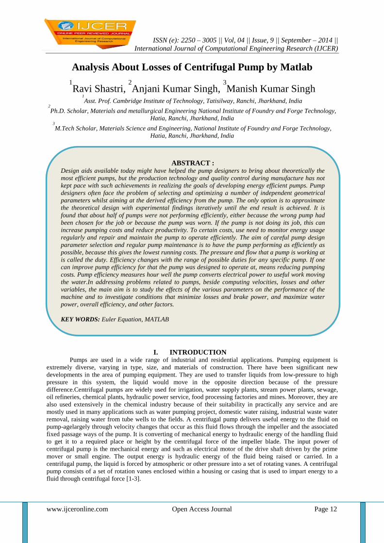
Fig: 1 Centrifugal Pump
A pump transfer mechanical energy from some external source to the liquid flowing through it and
losses occur in any energy conversion process. The energy transferred is predicted by the Euler Equation. The
energy transfer quantities are losses between fluid power and mechanical power of the impeller or runner. Thus,
centrifugal pump may be taken losses of energy. The kinds of loss of centrifugal pumps can be differentiated in
internal losses and external or mechanical losses. The internal loss is hydraulic losses or blade losses by friction,
variations of the effective area or changes of direction losses of quantity at the sealing places between the
impeller and housing at the rotary shaft seals. The external or mechanical loss is sliding surface losses by
bearing friction or seal friction [2, 4].
Data of Centrifugal Pump:
For design calculation, the design parameters are taken as follows:
Flow rate, Q = 0.00293 m3/s
Head, H = 10 m
Pump speed, n = 2900 rpm
density of water, ρ= 1000 kg/m3
Specific Speed: ns = 3.65n (1)
The water power is determined from the relationship
N= ρgHQ(2)
Shock Losses: The major loss considered is shock losses at the impeller inlet caused by the mismatch of fluid
and metal angles. Shock losses can be found everywhere in the flow range of the pump. Shock Losses are given
by following equation:

Analysis About Losses Of Centrifugal…
www.ijceronline.com Open Access Journal Page 14
hs = k(QS-QN)2 (3)
Where k is the coefficient of leakage loss which value is assumed as 0.005.
Maximum flow rate: QN = πD1b1Vm1(4)
Table (a) - Shock Losses versus Flow Rate Graph
Fig. 2 Shock Losses versus Flow Rate Graph
Fig. 2 is the flow rate versus the shock loss of head. The shock loss of head increases when the flow rate
decreases. Shock loss does not have in the design point condition. If this condition is over, the shock loss of
head is high.
Impeller Friction Losses: The impeller was designed that the width of the impeller would become small and
the friction loss at the flow passage would become large. Therefore to relive the increase in friction loss, radial
flow passage on the plane of the impeller was adopted [3, 5]. The friction losses can be found for energy
dissipation due to contact of the fluid with solid boundaries such as stationary vanes, impeller, casing, disk and
diffuser, etc.
The impeller friction losses are:
(5)
Table (b) - Impeller Friction Losses versus Flow Rater Graph
Analysis About Losses Of Centrifugal…
www.ijceronline.com Open Access Journal Page 15
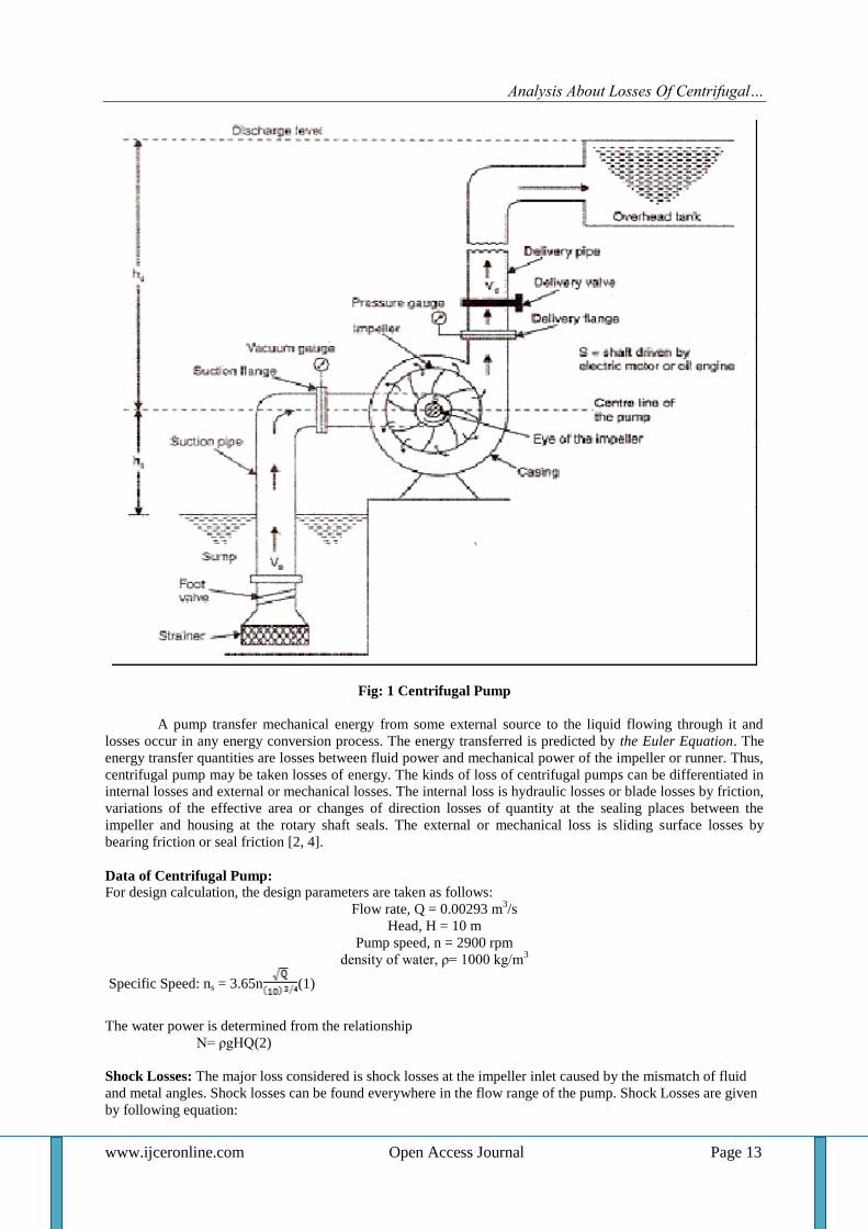
Fig. 3 Impeller Friction Losses versus Flow Rater Graph
The influence of the geometry of the impeller friction loss is obtained in Fig. 3. The analysis of the curves
shows that small differences between the points for the flow rate versus theimpeller friction loss of head. The
impeller loss of headincreases when the flow rate is increase.
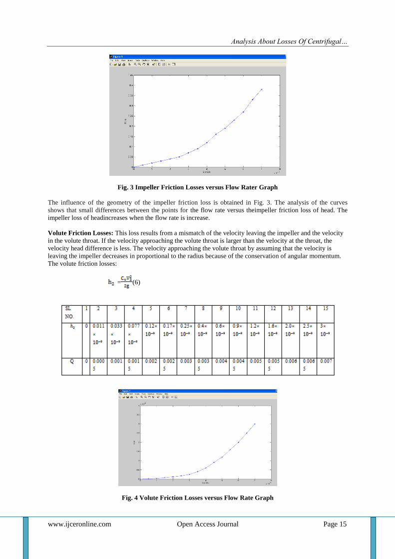
Volute Friction Losses: This loss results from a mismatch of the velocity leaving the impeller and the velocity
in the volute throat. If the velocity approaching the volute throat is larger than the velocity at the throat, the
velocity head difference is less. The velocity approaching the volute throat by assuming that the velocity is
leaving the impeller decreases in proportional to the radius because of the conservation of angular momentum.
The volute friction losses:
= (6)
Fig. 4 Volute Friction Losses versus Flow Rate Graph
Analysis About Losses Of Centrifugal…
www.ijceronline.com Open Access Journal Page 16
The volute friction losses versus flow rate graph are Fig. 4. The volute friction loss of head increases when the
flow rate is increased. The volute friction coefficient decreases for smallvalues of the volute flow coefficient.
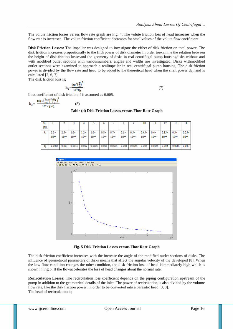
Disk Friction Losses: The impeller was designed to investigate the effect of disk friction on total power. The
disk friction increases proportionally to the fifth power of disk diameter In order toexamine the relation between
the height of disk friction lossesand the geometry of disks in real centrifugal pump housingdisks without and
with modified outlet sections with variousnumbers, angles and widths are investigated. Disks withmodified
outlet sections were examined to approach a realimpeller in real centrifugal pump housing. The disk friction
power is divided by the flow rate and head to be added to the theoretical head when the shaft power demand is
calculated [2, 6, 7].
The disk friction loss is;
= (7)
Loss coefficient of disk friction, f is assumed as 0.005.
= (8)
Table (d) Disk Friction Losses versus Flow Rate Graph
Fig. 5 Disk Friction Losses versus Flow Rate Graph
The disk friction coefficient increases with the increase the angle of the modified outlet sections of disks. The
influence of geometrical parameters of disks means that affect the angular velocity of the developed [8]. When
the low flow condition changes the other condition, the disk friction loss of head isimmediately high which is
shown in Fig.5. If the flowaccelerates the loss of head changes about the normal rate.
Recirculation Losses: The recirculation loss coefficient depends on the piping configuration upstream of the
pump in addition to the geometrical details of the inlet. The power of recirculation is also divided by the volume
flow rate, like the disk friction power, in order to be converted into a parasitic head [3, 8].
The head of recirculation is;
Analysis About Losses Of Centrifugal…
www.ijceronline.com Open Access Journal Page 17
= (9)
Impellers with relatively large inlet diameters usually encountered in high-specific speed pumps are the most
likely to re-circulate. The loss contains a default value of 0.005 for the loss coefficient. Coefficient of leakage
loss K is assumed as 0.005.The pump speed is carried out with the value of specific speed because impeller with
relatively large inlet diameters (usually encountered in high-specific-speed pumps) are the most likely to re-
circulate. Coefficient of leakage loss K is assumed as 0.005[4, 7, 9].
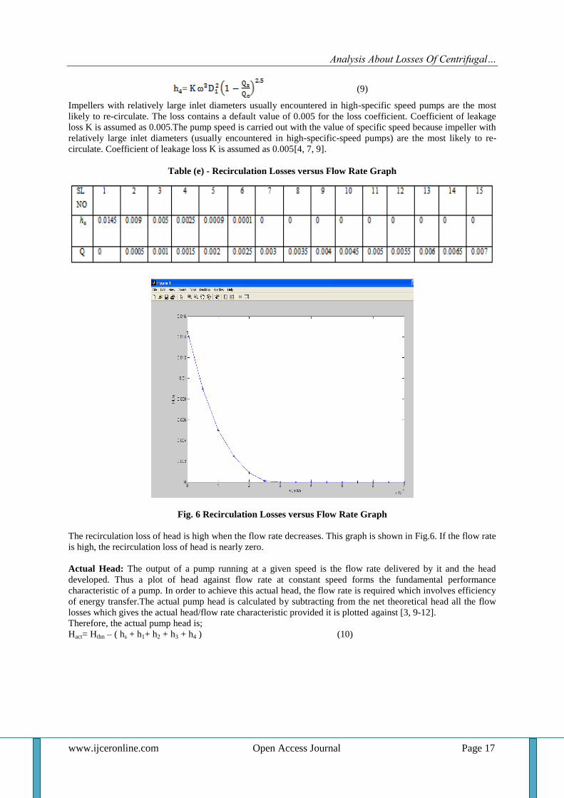
Table (e) - Recirculation Losses versus Flow Rate Graph
Fig. 6 Recirculation Losses versus Flow Rate Graph
The recirculation loss of head is high when the flow rate decreases. This graph is shown in Fig.6. If the flow rate
is high, the recirculation loss of head is nearly zero.
Actual Head: The output of a pump running at a given speed is the flow rate delivered by it and the head
developed. Thus a plot of head against flow rate at constant speed forms the fundamental performance
characteristic of a pump. In order to achieve this actual head, the flow rate is required which involves efficiency
of energy transfer.The actual pump head is calculated by subtracting from the net theoretical head all the flow
losses which gives the actual head/flow rate characteristic provided it is plotted against [3, 9-12].
Therefore, the actual pump head is;
Hact= Hthn – ( hs + h1+ h2 + h3 + h4 ) (10)
Analysis About Losses Of Centrifugal…
www.ijceronline.com Open Access Journal Page 18
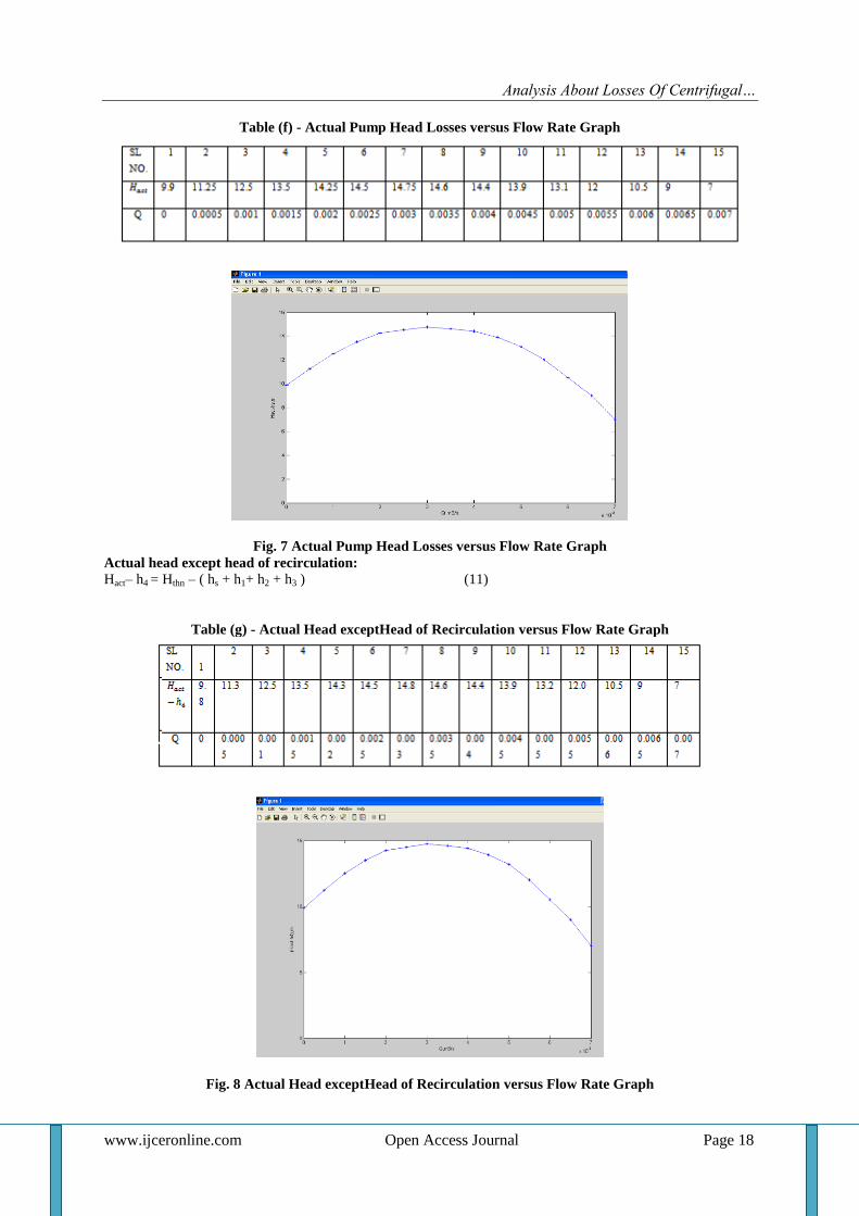
Table (f) - Actual Pump Head Losses versus Flow Rate Graph
Fig. 7 Actual Pump Head Losses versus Flow Rate Graph
Actual head except head of recirculation:
Hact– h4 = Hthn – ( hs + h1+ h2 + h3 ) (11)
Table (g) - Actual Head exceptHead of Recirculation versus Flow Rate Graph
Fig. 8 Actual Head exceptHead of Recirculation versus Flow Rate Graph
Analysis About Losses Of Centrifugal…
www.ijceronline.com Open Access Journal Page 19
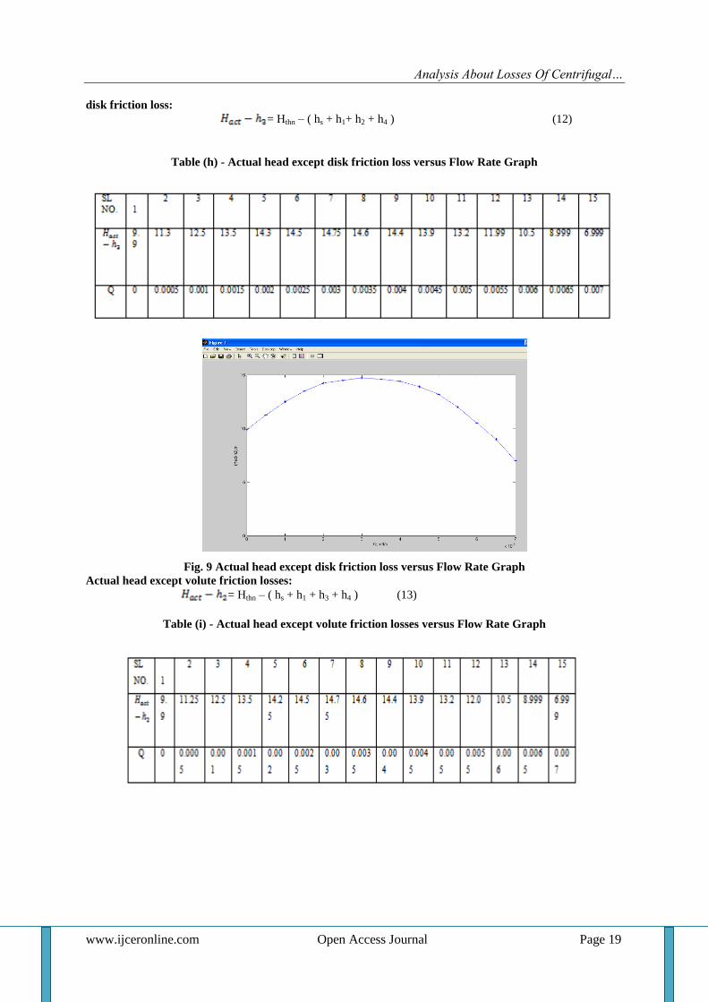
disk friction loss:
= Hthn – ( hs + h1+ h2 + h4 ) (12)
Table (h) - Actual head except disk friction loss versus Flow Rate Graph
Fig. 9 Actual head except disk friction loss versus Flow Rate Graph
Actual head except volute friction losses:
= Hthn – ( hs + h1 + h3 + h4 ) (13)
Table (i) - Actual head except volute friction losses versus Flow Rate Graph
Analysis About Losses Of Centrifugal…
www.ijceronline.com Open Access Journal Page 20
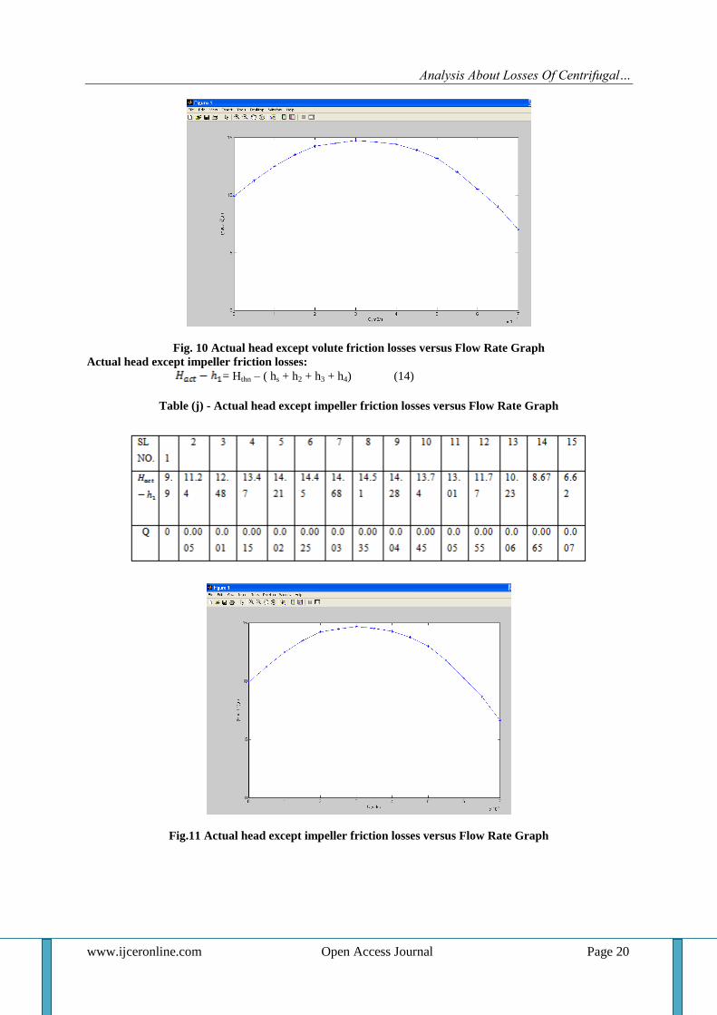
Fig. 10 Actual head except volute friction losses versus Flow Rate Graph
Actual head except impeller friction losses:
= Hthn – ( hs + h2 + h3 + h4) (14)
Table (j) - Actual head except impeller friction losses versus Flow Rate Graph
Fig.11 Actual head except impeller friction losses versus Flow Rate Graph
Analysis About Losses Of Centrifugal…
www.ijceronline.com Open Access Journal Page 21
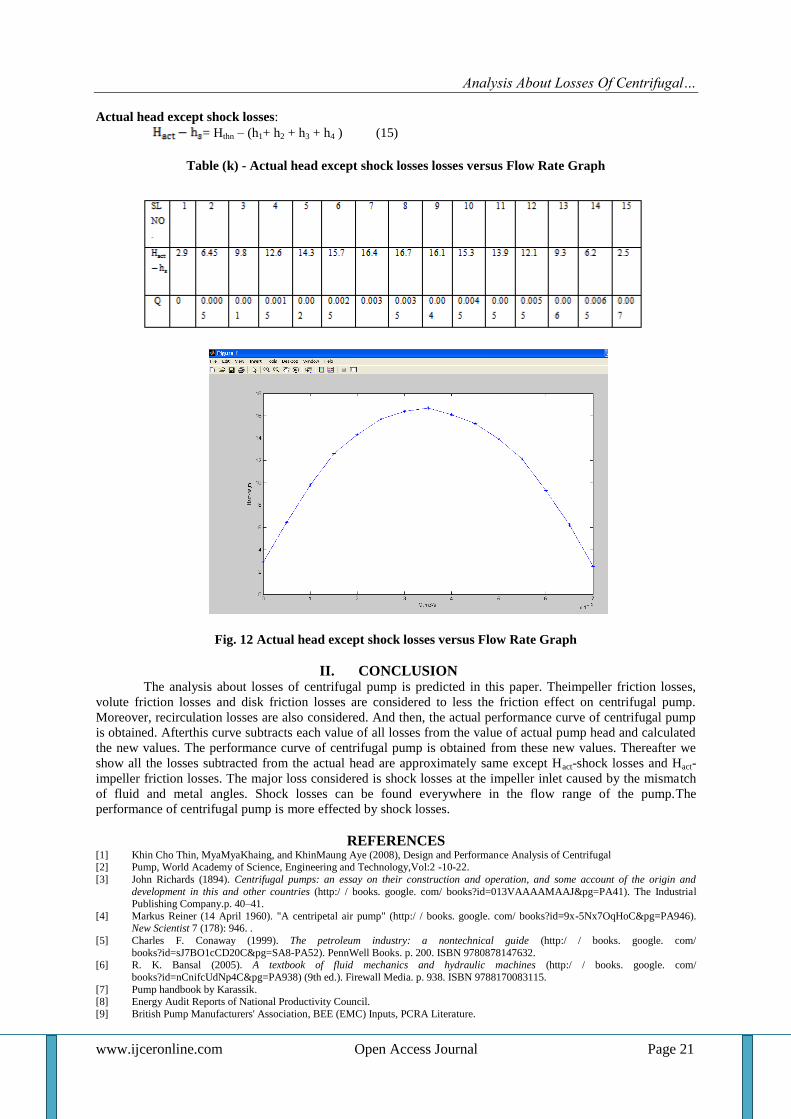
Actual head except shock losses:
= Hthn – (h1+ h2 + h3 + h4 ) (15)
Table (k) - Actual head except shock losses losses versus Flow Rate Graph
Fig. 12 Actual head except shock losses versus Flow Rate Graph
II. CONCLUSION The analysis about losses of centrifugal pump is predicted in this paper. Theimpeller friction losses,
volute friction losses and disk friction losses are considered to less the friction effect on centrifugal pump.
Moreover, recirculation losses are also considered. And then, the actual performance curve of centrifugal pump
is obtained. Afterthis curve subtracts each value of all losses from the value of actual pump head and calculated
the new values. The performance curve of centrifugal pump is obtained from these new values. Thereafter we
show all the losses subtracted from the actual head are approximately same except Hact-shock losses and Hact-
impeller friction losses. The major loss considered is shock losses at the impeller inlet caused by the mismatch
of fluid and metal angles. Shock losses can be found everywhere in the flow range of the pump.The
performance of centrifugal pump is more effected by shock losses.
REFERENCES [1] Khin Cho Thin, MyaMyaKhaing, and KhinMaung Aye (2008), Design and Performance Analysis of Centrifugal [2] Pump, World Academy of Science, Engineering and Technology,Vol:2 -10-22.
[3] John Richards (1894). Centrifugal pumps: an essay on their construction and operation, and some account of the origin and
development in this and other countries (http:/ / books. google. com/ books?id=013VAAAAMAAJ&pg=PA41). The Industrial Publishing Company.p. 40–41.
[4] Markus Reiner (14 April 1960). "A centripetal air pump" (http:/ / books. google. com/ books?id=9x-5Nx7OqHoC&pg=PA946). New Scientist 7 (178): 946. .
[5] Charles F. Conaway (1999). The petroleum industry: a nontechnical guide (http:/ / books. google. com/
books?id=sJ7BO1cCD20C&pg=SA8-PA52). PennWell Books. p. 200. ISBN 9780878147632. [6] R. K. Bansal (2005). A textbook of fluid mechanics and hydraulic machines (http:/ / books. google. com/
books?id=nCnifcUdNp4C&pg=PA938) (9th ed.). Firewall Media. p. 938. ISBN 9788170083115.
[7] Pump handbook by Karassik. [8] Energy Audit Reports of National Productivity Council.
[9] British Pump Manufacturers' Association, BEE (EMC) Inputs, PCRA Literature.
Analysis About Losses Of Centrifugal…
www.ijceronline.com Open Access Journal Page 22
[10] F. MOUKALLED and A. HONEIN (1997,1998 ), Computer-aided analysis ofhydraulicpumps,International Journal of Mechanical
Engineering Education Vol 27 No 4. [11] D. Rajenthirakumar&K. A. Jagadeesh (2009), Analysis of interaction between geometry and efficiency of impeller pump using
rapid prototyping, Int J AdvManufTechnol, 44:890–899.
[12] Mario Šavar, HrvojeKozmar, Igor Sutlović (2009), Improving centrifugal pump efficiency by impeller trimming, Desalination 249,654–659.
[13] LamloumiHedi, KanfoudiHatem, ZgolliRidha (2010), Numerical Flow Simulation in a Centrifugal Pump,International Renewable
Energy Congress November 5-7,Sousse, Tunisia.
Related Documents