Analog nonlinear MIMO receiver for optical mode division multiplexing transmission Arnaldo Spalvieri, 1 Pierpaolo Boffi, 1 Simone Pecorino, 1 Luca Barletta, 2 Maurizio Magarini, 1,∗ Alberto Gatto, 1 Paolo Martelli, 1 and Mario Martinelli 1 1 Dipartimento di Elettronica, Informazione e Bioingegneria, Politecnico di Milano, Piazza L. da Vinci 32, I-20133 Milano, Italy 2 Institute for Advanced Study, Technische Universit¨ at M¨ unchen, Lichtenbergstrasse 2a, D-85748 Garching, Germany ∗ [email protected] Abstract: The complexity and the power consumption of digital signal processing are crucial issues in optical transmission systems based on mode division multiplexing and coherent multiple-input multiple-output (MIMO) processing at the receiver. In this paper the inherent characteristic of spatial separation between fiber modes is exploited, getting a MIMO system where joint demultiplexing and detection is based on spatially separated photodetectors. After photodetection, one has a MIMO system with nonlinear crosstalk between modes. The paper shows that the nonlinear crosstalk can be dealt with by a low-complexity and non-adaptive detection scheme, at least in the cases presented in the paper. © 2013 Optical Society of America OCIS codes: (040.1240) Arrays; (060.2330) Fiber optics communications; (060.4080) Modu- lation; (060.4230) Multiplexing; (080.4865) Optical vortices. References and links 1. R. C. J. Hsu, A. Tarighat, A. Shah, A. H. Sayed, and B. Jalali, “Capacity enhancement in coherent optical MIMO (COMIMO) multimode fiber links,” IEEE Commun. Lett. 10, 195–197 (2006). 2. A. Tarighat, R. Hsu, A. Shah, A. Sayed, and B. Jalali, “Fundamentals and challenges of optical multiple-input multiple-output multimode fiber links,” IEEE Commun. Mag. 45, 57–63 (2007). 3. T. Morioka, Y. Awaji, R. Ryf, P. J. Winzer, D. Richardson, and F. Poletti, “Enhancing optical communications with brand new fibers,” IEEE Commun. Mag. 50, s31–s42 (2012). 4. R.-J. Essiambre and R. W. Tkach, “Capacity trends and limits of optical communication networks,” IEEE Proc. 100, 1035–1055 (2012). 5. R. Dar, M. Feder, and M. Shtaif, “The underaddressed optical multiple-input, multiple-output channel: capacity and outage,” Opt. Lett. 37, 3150–3152 (2012). 6. R. Dar, M. Feder, and M. Shtaif, “The Jacobi MIMO channel,” IEEE Trans. Inf. Theory 59, 2426–2441 (2013). 7. V. Sleiffer, Y. Jung, B. Inan, H. Chen, R. van Uden, M. Kuschnerov, D. van den Borne, S. Jansen, V. Vel- janovski, T. Koonen, D. Richardson, S. Alam, F. Poletti, J. Sahu, A. Dhar, B. Corbett, R. Winfield, A. Ellis, and H. De Waardt, “Mode-division-multiplexed 3×112-Gb/s DP-QPSK transmission over 80 km few-mode fiber with inline MM-EDFA and blind DSP,” in European Conference and Exhibition on Optical Communication, OSA Technical Digest (online) (Optical Society of America, 2012), paper Tu.1.C.2. 8. R. Ryf, S. Randel, A. H. Gnauck, C. Bolle, A. Sierra, S. Mumtaz, M. Esmaeelpour, E. C. Burrows, R.-J. Essi- ambre, P. J. Winzer, D. W. Peckham, A. H. McCurdy, and R. Lingle, “Mode-division multiplexing over 96 km of few-mode fiber using coherent 6×6 MIMO processing,” J. Lightwave Technol. 30, 521–531 (2012). 9. C. Koebele, M. Salsi, L. Milord, R. Ryf, C. Bolle, P. Sillard, S. Bigo, and G. Charlet, “40km transmission of five mode division multiplexed data streams at 100Gb/s with low MIMO-DSP complexity,” in European Conference #192628 - $15.00 USD Received 19 Jun 2013; revised 14 Aug 2013; accepted 4 Sep 2013; published 15 Oct 2013 (C) 2013 OSA 21 October 2013 | Vol. 21, No. 21 | DOI:10.1364/OE.21.025174 | OPTICS EXPRESS 25174

Welcome message from author
This document is posted to help you gain knowledge. Please leave a comment to let me know what you think about it! Share it to your friends and learn new things together.
Transcript

Analog nonlinear MIMO receiver foroptical mode division multiplexing
transmission
Arnaldo Spalvieri,1 Pierpaolo Boffi,1 Simone Pecorino,1 LucaBarletta,2 Maurizio Magarini,1,∗ Alberto Gatto,1 Paolo Martelli,1 and
Mario Martinelli11Dipartimento di Elettronica, Informazione e Bioingegneria, Politecnico di Milano,
Piazza L. da Vinci 32, I-20133 Milano, Italy2Institute for Advanced Study, Technische Universitat Munchen,
Lichtenbergstrasse 2a, D-85748 Garching, Germany∗[email protected]
Abstract: The complexity and the power consumption of digital signalprocessing are crucial issues in optical transmission systems based onmode division multiplexing and coherent multiple-input multiple-output(MIMO) processing at the receiver. In this paper the inherent characteristicof spatial separation between fiber modes is exploited, getting a MIMOsystem where joint demultiplexing and detection is based on spatiallyseparated photodetectors. After photodetection, one has a MIMO systemwith nonlinear crosstalk between modes. The paper shows that the nonlinearcrosstalk can be dealt with by a low-complexity and non-adaptive detectionscheme, at least in the cases presented in the paper.
© 2013 Optical Society of America
OCIS codes: (040.1240) Arrays; (060.2330) Fiber optics communications; (060.4080) Modu-lation; (060.4230) Multiplexing; (080.4865) Optical vortices.
References and links1. R. C. J. Hsu, A. Tarighat, A. Shah, A. H. Sayed, and B. Jalali, “Capacity enhancement in coherent optical MIMO
(COMIMO) multimode fiber links,” IEEE Commun. Lett. 10, 195–197 (2006).2. A. Tarighat, R. Hsu, A. Shah, A. Sayed, and B. Jalali, “Fundamentals and challenges of optical multiple-input
multiple-output multimode fiber links,” IEEE Commun. Mag. 45, 57–63 (2007).3. T. Morioka, Y. Awaji, R. Ryf, P. J. Winzer, D. Richardson, and F. Poletti, “Enhancing optical communications
with brand new fibers,” IEEE Commun. Mag. 50, s31–s42 (2012).4. R.-J. Essiambre and R. W. Tkach, “Capacity trends and limits of optical communication networks,” IEEE Proc.
100, 1035–1055 (2012).5. R. Dar, M. Feder, and M. Shtaif, “The underaddressed optical multiple-input, multiple-output channel: capacity
and outage,” Opt. Lett. 37, 3150–3152 (2012).6. R. Dar, M. Feder, and M. Shtaif, “The Jacobi MIMO channel,” IEEE Trans. Inf. Theory 59, 2426–2441 (2013).7. V. Sleiffer, Y. Jung, B. Inan, H. Chen, R. van Uden, M. Kuschnerov, D. van den Borne, S. Jansen, V. Vel-
janovski, T. Koonen, D. Richardson, S. Alam, F. Poletti, J. Sahu, A. Dhar, B. Corbett, R. Winfield, A. Ellis, andH. De Waardt, “Mode-division-multiplexed 3×112-Gb/s DP-QPSK transmission over 80 km few-mode fiberwith inline MM-EDFA and blind DSP,” in European Conference and Exhibition on Optical Communication,OSA Technical Digest (online) (Optical Society of America, 2012), paper Tu.1.C.2.
8. R. Ryf, S. Randel, A. H. Gnauck, C. Bolle, A. Sierra, S. Mumtaz, M. Esmaeelpour, E. C. Burrows, R.-J. Essi-ambre, P. J. Winzer, D. W. Peckham, A. H. McCurdy, and R. Lingle, “Mode-division multiplexing over 96 km offew-mode fiber using coherent 6×6 MIMO processing,” J. Lightwave Technol. 30, 521–531 (2012).
9. C. Koebele, M. Salsi, L. Milord, R. Ryf, C. Bolle, P. Sillard, S. Bigo, and G. Charlet, “40km transmission of fivemode division multiplexed data streams at 100Gb/s with low MIMO-DSP complexity,” in European Conference
#192628 - $15.00 USD Received 19 Jun 2013; revised 14 Aug 2013; accepted 4 Sep 2013; published 15 Oct 2013(C) 2013 OSA 21 October 2013 | Vol. 21, No. 21 | DOI:10.1364/OE.21.025174 | OPTICS EXPRESS 25174

and Exposition on Optical Communications, OSA Technical Digest (CD) (Optical Society of America, 2011),paper Th.13.C.3.
10. C. P. Tsekrekos, A. Martinez, F. M. Huijskens, and A. M. J. Koonen, “Design considerations for a transparentmode group diversity multiplexing link,” IEEE Photon. Technol. Lett. 18, 2359–2361 (2006).
11. H. S. Chen, H. P. A. van den Boom, and A. M. J. Koonen, “30Gbit/s 3×3 optical mode group division multiplex-ing system with mode-selective spatial filtering,” in Optical Fiber Communication Conference/National FiberOptic Engineers Conference, OSA Technical Digest (CD) (Optical Society of America, 2011), paper OWB1.
12. B. Franz and H. Bulow, “Mode group multiplexing over graded-index multimode fibers,” in Proceedings ofInternational Conference on Transparent Optical Networks, (2012), paper Th.A1.3.
13. M. Nazarathy and A. Agmon, “Coherent transmission direct detection MIMO over short-range optical intercon-nects and passive optical networks,” J. Lightwave Technol. 26, 2037–2045 (2008).
14. J. A. Carpenter, B. C. Thomsen, and T. D. Wilkinson, “2×56-Gb/s mode-division multiplexed transmission over2km of OM2 multimode fibre without MIMO equalization,” in European Conference and Exhibition on OpticalCommunication, OSA Technical Digest (online) (Optical Society of America, 2012), paper Th.2.D.3.
15. J. A. Carpenter, B. C. Thomsen, and T. D. Wilkinson, “Optical vortex based mode division multiplexing overgraded-index multimode fibre,” in Optical Fiber Communication Conference/National Fiber Optic EngineersConference, OSA Technical Digest (online) (Optical Society of America, 2013), paper OTh4G.3.
16. S. Murshid and J. Iqbal, “Array of concentric CMOS photodiodes for detection and de-multiplexing of spatiallymodulated optical channels,” Opt. Laser Tech. 41, 764–769 (2009).
17. S. N. Khonina, N. L. Kazanskiy, and V. A. Soifer, “Optical vortices in a fiber: mode division multiplexing andmultimode self-imaging,” in Recent Progress in Optical Fiber Research, M. Yasin, S. W. Harun, and H. Arof,eds. (InTech, 2012), pp. 327–352.
18. P. Martelli, A. Gatto, P. Boffi, and M. Martinelli, “Free-space optical transmission with orbital angular momentumdivision multiplexing,” Electron. Lett. 47, 972–973 (2011).
19. A. Gatto, M. Tacca, P. Martelli, P. Boffi, and M. Martinelli, “Free-space orbital angular momentum divisionmultiplexing with Bessel beams,” J. Optics 13, 064018 (2011).
20. J. Wang, J.-Y. Yang, I. Fazal, N. Ahmed, Y. Yan, H. Huang, Y. Ren, Y. Yue, S. Dolinar, M. Tur, and A. Willner,“Terabit free-space data transmission employing orbital angular momentum multiplexing,” Nat. Photonics 6,488–496 (2012).
21. N. Bozinovic, Y Yue, Y. Ren, M. Tur, P. Kristensen, A. Willner, and S. Ramachandran, “Orbital angular mo-mentum (OAM) based mode division multiplexing (MDM) over a km-length fiber,” in European Conference andExhibition on Optical Communication, OSA Technical Digest (online) (Optical Society of America, 2012), paperTh.3.C.6.
22. K.-P. Ho and J. M. Kahn, “Statistics of group delays in multimode fiber with strong mode coupling,” J. LightwaveTechnol. 29, 3119–3128 (2011).
23. C. Antonelli, A. Mecozzi, M. Shtaif, and P. J. Winzer “Stokes-space analysis of modal dispersion in fibers withmultiple mode transmission,” Opt. Express 20, 11718–11733 (2012).
1. Introduction
Mode Division Multiplexing (MDM) has attracted widespread attention as a means to increasethe information throughput over a single fiber [1–4]. Considerations about the capacity of opti-cal MDM can be found in [5, 6].
In recent experiments [7,8], MDM exploiting multiple-input multiple-output (MIMO) digitalsignal processing (DSP) in combination with coherent demultiplexing and detection has demon-strated its effectiveness in removing the intermodal crosstalk that originates during propagation.However, real-time coherent MIMO processing requires high complexity and power consump-tion at the receiver. A scheme performing optical demultiplexing before coherent detection,thus allowing reduced complexity compared to the fully coherent MIMO signal precessing, hasbeen proposed in [9].
Even simpler schemes, that are fully noncoherent, have been considered in [10–12]. Such ap-proaches rely upon the assumption of having groups of modes that are well separated in terms ofpropagation constants, so that the crosstalk between them, when used as independent channels,can be considered negligible at the receiver. The low crosstalk condition is achieved in [10]by considering a fiber with a core radius that is large enough to guarantee that the multiplexedmode groups remain well spatially separated after propagation over the fiber. Spatial detectionis then carried out on each group independently by means of circular multi-segment Photode-
#192628 - $15.00 USD Received 19 Jun 2013; revised 14 Aug 2013; accepted 4 Sep 2013; published 15 Oct 2013(C) 2013 OSA 21 October 2013 | Vol. 21, No. 21 | DOI:10.1364/OE.21.025174 | OPTICS EXPRESS 25175
tectors (PDs). Assuming linear superposition of the power distributions at the fiber output, aMIMO channel matrix is estimated, without implementing a real mode group division multi-plexing transmission, in order to perform detection. On another hand, the requirement for wellseparated propagation constants is used as a prerequisite in [11] for experimental transmissionof mode groups over a distance in the order of tens of meters. In this case, the short propagationdistance introduces a relatively low crosstalk that can be easily mitigated by mode-selectivespatial filtering. This spatial filtering is based on the use of a number of standard single-modefibers equals to the number of the transmitted mode groups. As in [10], the experimental inves-tigation done in [12] does not implement a real mode group division multiplexed transmission.In the considered experimental analysis the number of mode groups that can be used as sep-arate spatial channels for on-off keying transmission over a 2 km long standard graded-indexmultimode fiber is firstly determined and the error performance for each mode group, whenused as an individual channel, is then evaluated. A lower conversion efficiency is shown forhigher-order modes with respect to the fundamental mode, due to imperfect mode conversionat the transmitter, that is responsible for performance degradation.
This paper considers an MDM scheme that is candidate for application in those systemswhere cost, power consumption, and complexity, are relevant issues, such as local area networksand optical interconnects for data centers. In this context of short-range optical communicationlinks (i.e., up to a few kilometers), the impact of chromatic dispersion and modal dispersion isnegligible also for high bit rate [13]. The main motivation behind our work is the observationthat the detection techniques proposed in [10–12] are designed by assuming a low level ofintermodal crosstalk and, as such, they are not able to fully take into consideration its effects.To this aim, a first step toward the characterization of such a crosstalk has been done in [14,15].In particular, a penalty in the order of 2 dB is shown for optical mode group demultiplexingwithout any MIMO processing compared to single channel transmission in a standard 50 μm-core graded-index multimode fiber for lengths of 2 km and of 8 km. In the present paper,we propose a novel MDM scheme that is able to cope with the intermodal crosstalk. The paperfocuses on two-mode multiplexing, and, starting from the mode coupling model of [5,6], showsthat, after detection by two spatially separated concentric PDs [16], one gets a MIMO channelwith nonlinear crosstalk, that, in the above mentioned applicative context, can be dealt with byMIMO processing of low complexity.
2. System model
Let us consider MDM transmission in optical fiber based on the excitation of two modes, calledmode 1 and mode 2, that are on-off keying modulated and characterized by the same energy. TheMIMO alphabet A is therefore made by the four column vectors a = [a1,a2]
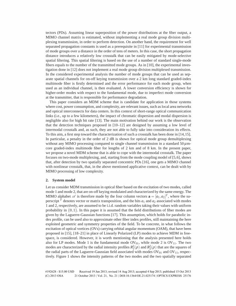
T , where the su-perscript T denotes vector or matrix transposition, and the bits a1 and a2 associated with modes1 and 2, respectively, are assumed to be i.i.d. random variables taking their values with uniformprobability in {0,1}. In this paper it is assumed that the field distributions of fiber modes aregiven by the Laguerre-Gaussian functions [17]. This assumption, which holds for parabolic in-dex profile, can be used also to approximate other fiber index profiles, still maintaining the hereexploited geometric and symmetry properties of the field. To be concrete, in what follows theexcitation of optical vortices (OVs) carrying orbital angular momentum (OAM), that have beenproposed in [15], [18–21] in place of Linearly Polarized (LP) modes to achieve MDM in free-space, is considered. However, it is worth mentioning that the analysis presented here holdsalso for LP modes. Mode 1 is the fundamental mode OV01, while mode 2 is OV11. The twomodes are characterized by the radial intensity profiles R2
1(ρ) and R22(ρ) that are the squares of
the radial parts of the Laguerre-Gaussian field associated with modes OV01 and OV11, respec-tively. Figure 1 shows the intensity patterns of the two modes and the two spatially separated
#192628 - $15.00 USD Received 19 Jun 2013; revised 14 Aug 2013; accepted 4 Sep 2013; published 15 Oct 2013(C) 2013 OSA 21 October 2013 | Vol. 21, No. 21 | DOI:10.1364/OE.21.025174 | OPTICS EXPRESS 25176

PD2
PD1
Fig. 1. From left to right: intensity pattern of OV01 and intensity pattern of OV11 beforecoupling. Rightmost picture: inner circle PD1, outer circular annulus PD2.
PDs matched to the two modes.Owing to mechanical perturbations (like twisting, bending, and vibrations) applied to the
fiber, mode coupling during propagation can take place, leading to intermodal crosstalk. More-over, mode coupling can be introduced at the transmitter due to imperfect mode conversionin the desired mode group. The experimental characterization of intermodal crosstalk made forLP [14] and OV [15] modes suggests that the strong random mode coupling regime [22,23] doesnot apply in short-range (i.e., up to lengths of a few kilometers) standard multimode fiber-opticlinks. In this case the crosstalk among mode groups is mainly induced by the imperfect gener-ation of the multiplexed modes and is more relevant for higher-order modes. In the followingwe introduce the crosstalk matrix between the modes corresponding to OV01 and OV11. Morein detail, the fundamental mode OV01 is two-fold degenerate in the circularly polarized modeswith opposite handedness OVleft
01 and OVright01 , that are associated with electrical fields �E1(ρ ,θ)
and �E2(ρ ,θ), both with radial intensity profile R21(ρ). Moreover, OV11 represents the group
of four modes OV+left11 , OV−left
11 , OV+right11 , and OV−right
11 , according to the different handednessof circular polarization (left/right) and OAM (+/-), that are associated with the electrical fields�E3(ρ ,θ), �E4(ρ ,θ), �E5(ρ ,θ), and �E6(ρ ,θ), all with radial intensity profiles R2
2(ρ). Note thatthe Laguerre-Gauss field distribution we are considering only focuses on the two-dimensionaltransverse components of the fields. The electrical field at the output of the fiber can be mod-elled as
�E(ρ ,θ ,a) = E(ρ ,θ) ·C ·a, (1)
where · is the vector-matrix product,
E(ρ ,θ) = [�E1(ρ ,θ), �E2(ρ ,θ), · · · ,�E6(ρ ,θ)],
and C is a 6× 2 matrix consisting of the two columns corresponding to the two transmittedmodes of the 6× 6 unitary crosstalk matrix [5, 6]. It is worth noting that a unitary crosstalkmatrix is energy conserving.
3. Mode separation by circular PDs
After mode coupling, direct detection by the two spatially separated PDs of Fig. 1 gives the twosignals
zi(a) =∫
Si
||�E(ρ ,θ ,a)||2 ρ dρ dθ , i = {1,2}, (2)
where Si is the surface of the i-th PD. By plugging (1) into (2) and by taking into account thebeating between �Ek and �Eh given by Eq. (5) in the Appendix and following the calculationsthere reported, one obtains the nonlinear MIMO model
z(a) = F ·P ·a+w(a),
#192628 - $15.00 USD Received 19 Jun 2013; revised 14 Aug 2013; accepted 4 Sep 2013; published 15 Oct 2013(C) 2013 OSA 21 October 2013 | Vol. 21, No. 21 | DOI:10.1364/OE.21.025174 | OPTICS EXPRESS 25177

Fig. 2. Realizations of intensity patterns after propagation with p1 = p2 = 0.8. From theupper to the lower row: a = [1,0]T , a = [0,1]T , and a = [1,1]T .
where z(a) = [z1(a),z2(a)]T , w(a) is a N ×1 vector, and the product F ·P is
[ ∫S1
R21(ρ)ρ dρ dθ
∫S1
R22(ρ)ρ dρ dθ∫
S2R2
1(ρ)ρ dρ dθ∫
S2R2
2(ρ)ρ dρ dθ
]·[
p1 1−p2
1−p1 p2
],
where coefficients 0≤ p1 ≤1 and 0≤ p2 ≤1 that characterize the crosstalk are reported in theAppendix. The term w(a) depends in a nonlinear manner on a:
w(a) = a1a2wi,
where i = [√
0.5,−√0.5]T and w is a random variable that is bounded as follows:
w ≤ 2√
2||F · i||√
pmax(1− pmin),
with pmax = max(p1, p2) and pmin = min(p1, p2).Figure 2 shows the intensity patterns of several realizations of the mode coupling given by
(1). Note that in [10], where intermodal crosstalk is not considered, one has that P is the identitymatrix and that w(a) is zero.
4. Mode separation by optical demultiplexing
As an adversary to our proposed approach, we consider a scheme based on optical mode de-multiplexing where the optical demultiplexer ideally separates the six modes comprised in thefamilies OV01 and OV11 [13]. We assume direct detection after optical demultiplexing, there-fore six PDs are used, one for each of six outputs of the demultiplexer. The PDs’ outputs canbe collected in the vector:
z(a) = P ·a+w(a),
where P is the 6×2 matrix containing the squared magnitude of elements ci, j of C and
#192628 - $15.00 USD Received 19 Jun 2013; revised 14 Aug 2013; accepted 4 Sep 2013; published 15 Oct 2013(C) 2013 OSA 21 October 2013 | Vol. 21, No. 21 | DOI:10.1364/OE.21.025174 | OPTICS EXPRESS 25178

Trans-impedance
ElectricalNetwork
DecisionLogic
a1
a2
z1
z2
PD1
PD2
y2
y1Trans-impedance
Fig. 3. Receiver block diagram.
w(a) = 2a1a2ℜ
⎧⎪⎪⎪⎨⎪⎪⎪⎩
⎡⎢⎢⎢⎣
c∗1,1c1,2
c∗2,1c2,2...
c∗6,1c6,2
⎤⎥⎥⎥⎦
⎫⎪⎪⎪⎬⎪⎪⎪⎭,
where ℜ{x} is the vector that collects the real parts of each element of vector x, and the super-script ∗ denotes complex conjugation.
5. MIMO processing
Considering short reach without optical amplifiers, the noisy signal after photodetection is y =z(a)+ n, where n is an additive white Gaussian noise (AWGN) vector with variance σ2
n perPD. The optimal decision rule about the transmitted vector a is the maximum likelihood (ML)rule, which, when AWGN affects the received signal, is
aML = argmina∈A
(y− z(a))T · (y− z(a)). (3)
The block diagram of the receiver based on spatially separated PDs is reported in Fig. 3. Theblock called electrical network produces the four differences (y−z(a)) by biasing y by the fourbiases z(a) and then squares the four results. The block called decision logic, that can be basedon few logic elements operating at symbol frequency, compares the four squared distances anddecides in favor of the vector a associated with the minimum squared distance.
6. Simulation results
Hereafter the performance of the two schemes presented above is compared. Figure 4 reportsthe symbol error rate (SER) for p1 = p2 = p against the ratio
R =E{(∑N
i=1 zi)2}
Nσ2n
,
where E{·} is the expectation operator, N is the number of PDs, and E{(∑Ni=1 zi)
2}/N is propor-tional to the mean square of the optical power that reaches each PD. We adopt E{(∑N
i=1 zi)2}/N
as a figure of merit because it depends on the input optical power only, while it is independentof the mode coupling generated during propagation. In the case of spatially separated PDs, wefound that the optimal radius of the inner PD is fairly insensitive to p and R. Figure 4 shows thatalso the sensitivity of the SER to p is moderate. It is worth observing that, from the reportedresults, it appears that the ML rule for p = 1 is virtually optimal also for p = 0.9 and p = 0.8.The reason behind this can be seen from the decision boundary reported in Fig. 5. From Fig. 5it is apparent that the error between [0,1]T and [1,0]T dominates the performance, and that the
#192628 - $15.00 USD Received 19 Jun 2013; revised 14 Aug 2013; accepted 4 Sep 2013; published 15 Oct 2013(C) 2013 OSA 21 October 2013 | Vol. 21, No. 21 | DOI:10.1364/OE.21.025174 | OPTICS EXPRESS 25179

5 10 15 20 2510
−4
10−3
10−2
10−1
100
R[dB]
SER
5 10 15 20 2510
−4
10−3
10−2
10−1
100
R[dB]
SER
5 10 15 20 2510
−4
10−3
10−2
10−1
100
R[dB]
SER
Fig. 4. From top to bottom: SER versus R with p= 1, p= 0.9, and p= 0.8. Solid line:circular PDs with ML decision. Asterisks: circular PDs with suboptimal decision (ML rulefor p= 1). Dashed line: 20 realizations of C and optical demultiplexing with ML detection.
#192628 - $15.00 USD Received 19 Jun 2013; revised 14 Aug 2013; accepted 4 Sep 2013; published 15 Oct 2013(C) 2013 OSA 21 October 2013 | Vol. 21, No. 21 | DOI:10.1364/OE.21.025174 | OPTICS EXPRESS 25180

0 0.5 1 1.5
0
0.5
1
1.5
z1
z 2
a1=1
a2=0
a1=1
a2=1a
1=0
a2=1
a1=0
a2=0
Fig. 5. Asterisks: z(a) with p = 1. Circles: 20 realizations of z(a) with p = 0.8. The solidline bounds the decision regions of the ML rule for p = 1. From the position of the circlesin the plane one realizes that the optimal decision boundary for p = 0.8 is virtually thesame as that for p = 1.
ML decision boundary for p = 1 remains virtually optimal for discriminating between [0,1]T
and [1,0]T also when crosstalk is present. As a consequence, MIMO processing can be non-adaptive. With optical demultiplexing there are infinitely many matrices C that lead to the samevalue of p, the performance depending on the specific C, as the families of curves reported inFig. 4 shows. In the Fig. for each considered value of p only 20 curves, out of the 104 obtainedby randomly generating matrix C, have been reported for readability reasons. The lower and up-per curves correspond, respectively, to the best and the worse performance we observed amongthe 104 random realizations of the matrix C, while the other 18 curves were obtained by ran-domly choosing among the remaining matrices C. From Fig. 4 we observe that also taking theworst case, optical demultiplexing outperforms spatially separated PDs, but the implementationof (3) is much more demanding in terms of signal processing. Specifically, besides the devicefor optical demultiplexing, ML detection after optical demultiplexing and photodetection needsa quite complex 6-dimensional MIMO processing that should adaptively match the specific ma-trix C. This adaptive matching to the matrix C explains the better performance achieved by theoptical demultiplexing approach compared to our proposed non-adaptive scheme.
7. Conclusions
A nonlinear MIMO system exploiting the inherent characteristic of optical modes in fiber ina direct detection scheme based on circular concentric PDs has been proposed and comparedto MIMO based on optical demultiplexing with direct detection. The advantage of circularconcentric PDs is that the receiver does not require high-speed sampling and DSP to detect thetransmitted bits, being devised here a low cost, low consumption solution, not requiring anyadaptive processing.
#192628 - $15.00 USD Received 19 Jun 2013; revised 14 Aug 2013; accepted 4 Sep 2013; published 15 Oct 2013(C) 2013 OSA 21 October 2013 | Vol. 21, No. 21 | DOI:10.1364/OE.21.025174 | OPTICS EXPRESS 25181

Appendix
The intensity of electrical field in (1) is
I(ρ ,θ ,a) = ||�E(ρ ,θ ,a)||2 = E(ρ ,θ) ·G(a) ·EH(ρ ,θ) (4)
with
G(a) = C ·a ·aH ·CH =
[G1,1(a) G1,2(a)G2,1(a) G2,2(a)
]
C =
[c1,1 c1,2
c2,1 c2,2
],
where the superscript H denotes transposition and complex conjugation. These matrices havebeen partitioned considering the two families of modes: for k,h ∈ {1,2}, Gk,h(a) is an mk ×mh
matrix, while ck,h is an mk×1 vector, with m1 = 2 and m2 = 4. Thanks to the circular symmetryof PDs, the beating between any two of the considered fields is such that
∫Si
�Ek(ρ ,θ) ·�E∗h (ρ ,θ)ρ dρ dθ =
{∫Si
R2k(ρ ,θ)ρ dρ dθ k = h
0 k �= h, (5)
with i = {1,2}. By using the above property and plugging (4) into (2), the output of i-th PDbecomes
zi(a) =6
∑k=1
6
∑h=1
gk,h(a)∫
Si
�Ek(ρ ,θ) ·�E∗h (ρ ,θ)ρ dρ dθ
= tr{G1,1(a)} fi,1 + tr{G2,2(a)} fi,2 , (6)
where tr{·} indicates the trace operator of a square matrix, G(a) =[gk,h(a)
]and
fi, j =∫
Si
R2j(ρ)ρ dρ dθ .
The trace of G j, j(a) is
tr{
G j, j(a)}=
2
∑k=1
2
∑h=1
akahcHj,k · c j,h.
By separating the linear and nonlinear part of this equation and plugging it into (6) one obtains
zi(a) = [ fi,1 fi,2] ·P ·a+2a1a2[ fi,1 fi,2] ·ℜ{[
cH1,1 · c1,2
cH2,1 · c2,2
]},
and
P =
[||c1,1||2 ||c1,2||2||c2,1||2 ||c2,2||2
]=
[p1 1− p2
1− p1 p2
].
In order to obtain the nonlinear MIMO model, the outputs of two PDs can be collected in thevector
z(a) =[z1(a)z2(a)
]= F ·P ·a+w(a),
#192628 - $15.00 USD Received 19 Jun 2013; revised 14 Aug 2013; accepted 4 Sep 2013; published 15 Oct 2013(C) 2013 OSA 21 October 2013 | Vol. 21, No. 21 | DOI:10.1364/OE.21.025174 | OPTICS EXPRESS 25182

with F = [ fi, j] and the nonlinear term
w(a) = 2a1a2F ·ℜ{[
cH1,1 · c1,2
cH2,1 · c2,2
]}. (7)
According to the unitary property of C,
cH1,1 · c1,2 =−cH
2,1 · c2,2 = αe jφ .
Substituting this relation in (7), the nonlinear term becomes
w(a) = 2√
2a1a2α cos(φ)F · i
where i = [√
0.5,−√0.5]T is the unit vector with slope −1. By using the assumption that the
two modes have the same energy, the following relation holds
F · i = γ i,
with γ ≥ 0. Using Schwarz’s inequality, one obtains
α cos(φ)≤ min(|cH
1,1 · c1,2|, |cH2,1 · c2,2|
)≤ min
(√p1(1− p2),
√p2(1− p1)
),
leading tow(a) = a1a2w i,
where pmax = max(p1, p2) , pmin = min(p1, p2), and
w =2√
2α cos(φ)γ ≤ 2√
2γ√
pmax(1− pmin).
#192628 - $15.00 USD Received 19 Jun 2013; revised 14 Aug 2013; accepted 4 Sep 2013; published 15 Oct 2013(C) 2013 OSA 21 October 2013 | Vol. 21, No. 21 | DOI:10.1364/OE.21.025174 | OPTICS EXPRESS 25183
Related Documents