VAPORIZERS Tec 1 to Tec 5 MODERATOR: DR SARIKA SPEAKER: DR PREETI

Welcome message from author
This document is posted to help you gain knowledge. Please leave a comment to let me know what you think about it! Share it to your friends and learn new things together.
Transcript
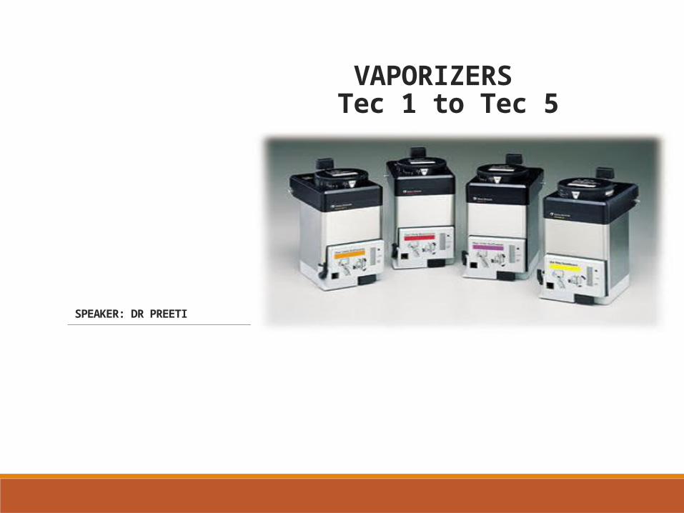
VAPORIZERS Tec 1 to Tec 5
MODERATOR: DR SARIKA
SPEAKER: DR PREETI
INTRODUCTION
Inhalational anaesthetic agents are usually liquids at room temperature and barometric pressure and need to be converted to vapour before being used and this conversion is effected using a vaporizer.Modern vaporizers are flow and temperature compensated, concentration calibrated, direct reading, dial controlled and are unaffected by positive pressure ‑ventilation.
The concentration of vapour is continuously monitored and adjusted by altering fresh gas flow through the vaporizerSafety features include an anti spill and a specific ‑vaporizer filling device.
Vaporizers and Standards
The ASTM anesthesia workstation standard contains the following provisions regarding vaporizers:
The effects of variations in ambient temperature and pressure, tilting, back pressure, and input flow rate and gas mixture composition on vaporizer performance must be stated in the accompanying documents.
The average delivered concentration from the vaporizer shall not deviate from the set value by more than ±20% or ±5% of the maximum setting, whichever is greater, without back pressure.
The average delivered concentration from the vaporizer shall not deviate from the set value by more than +30% or -20% or by more than +7.5% or -5% of the maximum setting, whichever is greater, with pressure fluctuations at the common gas outlet of 2 kPa with a total gas flow of 2 L/minute or 5 kPa with a total gas flow of 8 L/minute.
A system that prevents gas from passing through the vaporizing chamber or reservoir of one vaporizer and then through that of another must be provided.
The output of the vaporizer shall be less than 0.05% in the “OFF” or “zero” position if the “zero” position is also the “OFF” position.
All vaporizer control knobs must open counterclockwise.
Either the maximum and minimum filling levels or the actual usable volume and capacity shall be displayed.
The vaporizer must be designed so that it cannot be overfilled when in the normal operating position.
Vaporizers outside the breathing system must have noninterchangeable proprietary or 23-mm fittings and the inlet of the vaporizer must be male and the outlet female.
Vaporizers suitable for use in the breathing system must have standard 22-mm fittings or screw-threaded, weight-bearing fittings with the inlet female and the outlet male.
The direction of gas flow must be indicated by arrows and the vaporizer marked “for use in the breathing system.”
In order to give clinically useful concentrations of the agent, the anaesthetic vapor has to be diluted with fresh gas in one of the two ways:
1)By splitting the fresh gas flow so that only a portion passes through the vaporizing chamber and the rest bypasses it – variable bypass vaporizers.
2)By injecting the vapor directly to the total fresh gas flow without any split – measured flow vaporizers.
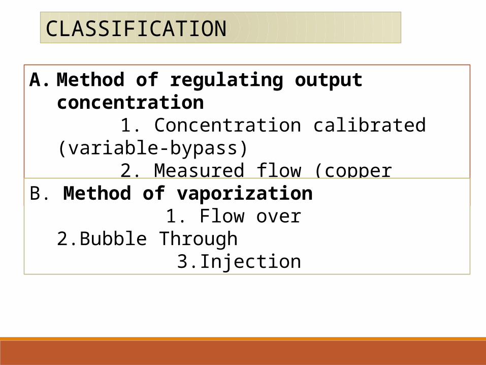
A. Method of regulating output concentration 1. Concentration calibrated (variable-bypass) 2. Measured flow (copper Kettle)
CLASSIFICATION
B. Method of vaporization 1. Flow over
2.Bubble Through 3.Injection
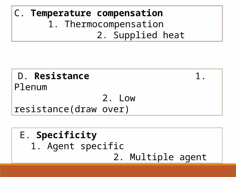
C. Temperature compensation 1. Thermocompensation
2. Supplied heat
E. Specificity 1. Agent specific
2. Multiple agent
D. Resistance 1. Plenum
2. Low resistance(draw over)
F.POSITION
1.VAPORIZER INSIDE CIRCUIT
2.VAPORIZER OUTSIDE CIRCUIT
TEC 1
introduced by Cyprane company in 1956 as FLUOTEC 1 for Halothane. Also called Mark 1. Problem of proportioning valve sticking there is a risk of overdose.
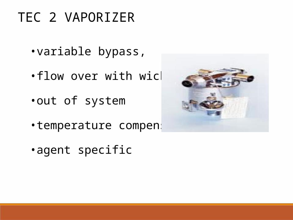
•variable bypass,
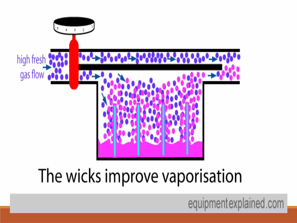
•flow over with wick
•out of system
•temperature compensated
•agent specific
TEC 2 VAPORIZER
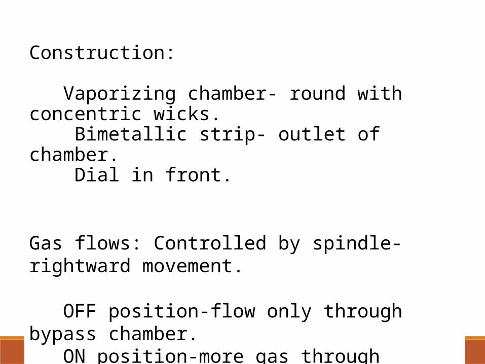
Construction:
Vaporizing chamber- round with concentric wicks. Bimetallic strip- outlet of chamber. Dial in front.
Gas flows: Controlled by spindle- rightward movement.
OFF position-flow only through bypass chamber. ON position-more gas through vaporizing chamber.

In a bimetallic strip, two metals with very different coefficients of thermal expansion are fixed together.
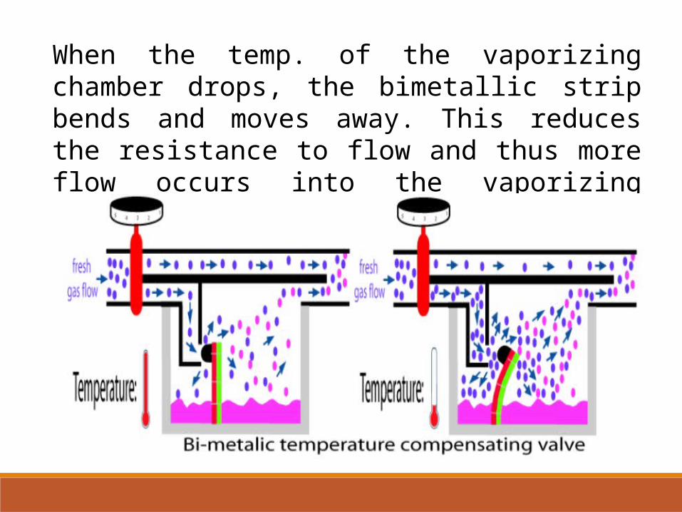
When the temp. of the vaporizing chamber drops, the bimetallic strip bends and moves away. This reduces the resistance to flow and thus more flow occurs into the vaporizing chamber
TEC 2 Evaluation and Use
Not accurate below 4Liters/min. With flow<2L/min, at low dial setting <2%, output is less than setting and more than setting with more dial setting.
With N2O gives lower output at higher setting and higher at lower settings.
With dial setting bet 0% and OFF, some output can occur varying with gas flow.
Prone to pumping effect at low flows and pressuring effect at high flows.
Small leak in the off position.
Disadvantages Halothane preservative Thymol gets deposited in vaporizer causing operating spindle to stick. Back pressure forcing saturated Vapour back into bypass chamber. High concentration at low flows.
TEC 3Models Fluotec Mark 3 Pentec Mark 2 Enfluratec Fortec
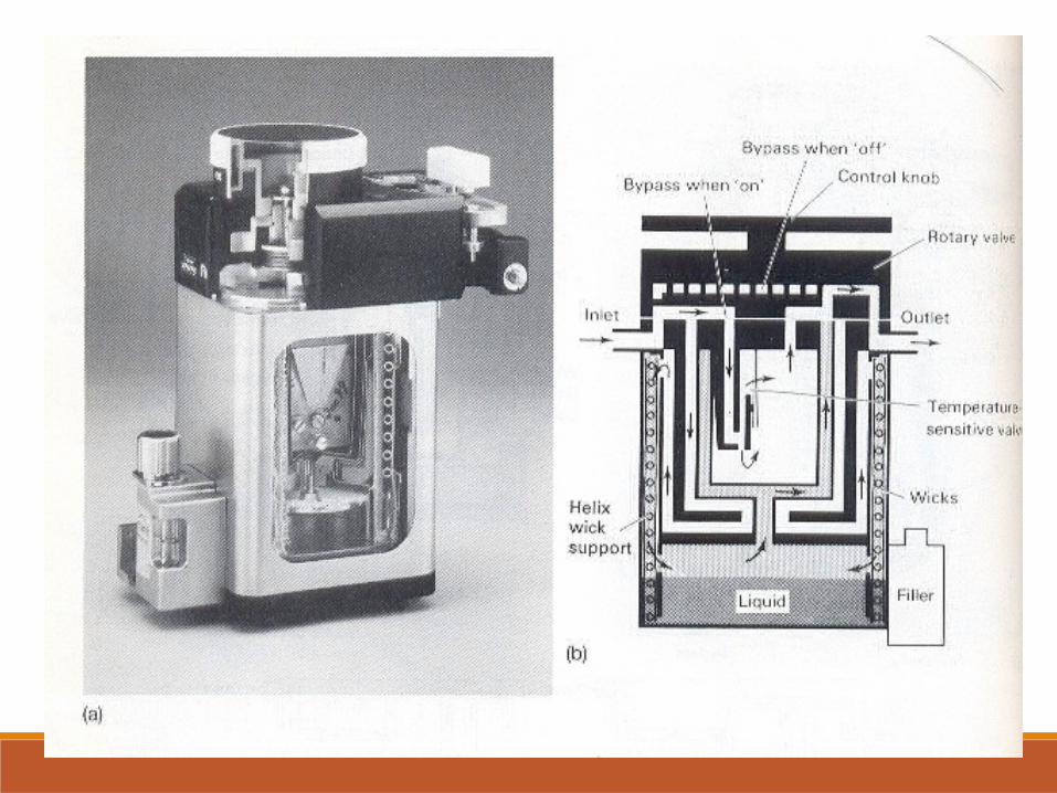
TEC 3 - Parts The VC has two concentric wick skirts, which enclose nickel plated copper helix in between.
This assembly forms a long spiral channel through which carrier gas flows before entering the VC preventing back pressure problems.
The bimetallic strip within the bypass chamber increases flow through the bypass chamber when temperature increase.
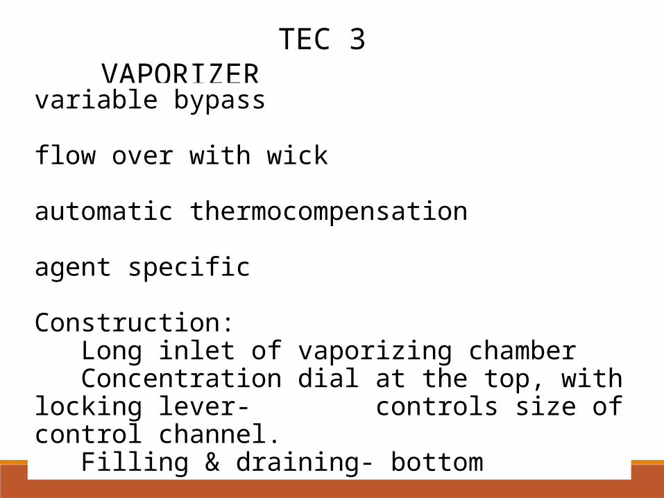
TEC 3 VAPORIZER
variable bypass
flow over with wick
automatic thermocompensation
agent specific
Construction: Long inlet of vaporizing chamber Concentration dial at the top, with locking lever- controls size of control channel. Filling & draining- bottom
TEC 3 Evaluation and Use
All are accurate at lower dial settings. At high dial settings, higher than expected concentration at low flow rates and vice versa.
Negligible effect of- O2 Flush, back pressure, increase or decrease of carrier gas.
N2O has little effect. Between OFF and 0.5%, output was less effected by FGF than in TEC 2.
Small leaks in bypass in OFF position. Tipping upto 90 degree does not affect output.
TEC 3 Disadvantages
Dial rotation problems-
rotation beyond OFF position.
rotated by 180 degree.
leak from dial setting because of damage or compression of gasket.
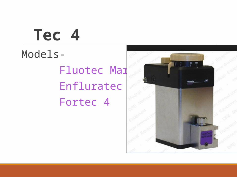
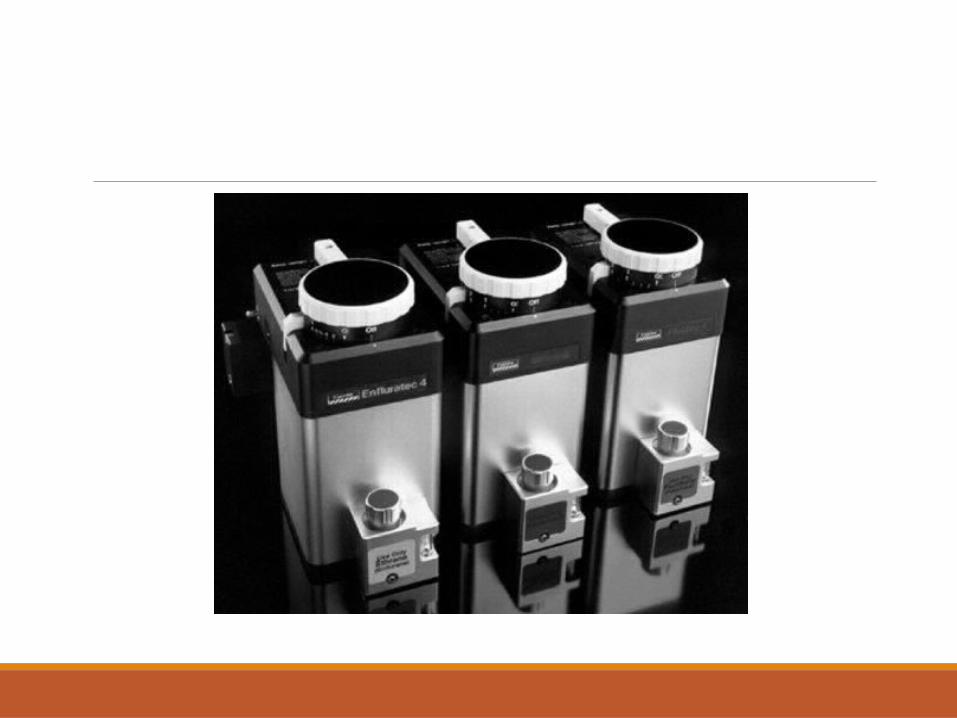
Tec 4Models- Fluotec Mark 4 Enfluratec 4 Fortec 4
Tec 4 A vapouriser designed for ‘out-of-circuit’ use in continuous flow techniques of inhalation anaesthesia with built in temperature-compensated and pressure-compensated capabilities.
The Tec 4 was introduced for BOC Model 2000 anaesthetic machine in 1983.
It was a remodelled Tec 3.
To overcome the problems of Tec 3 it incorporated internal baffle system to reduce the danger of liquid agent entering the bypass chamber on tilting.
Another interesting modification, to ensure only a single vapouriser operation at any time, was the safety interlock system.
This vapouriser is available for different specific agents, i.e. enflurane (dial setting range 0-7%), halothane (0-5%), isoflurane (0-5%)
TEC 4 Parts On top- Control Dial that is turn clockwise to increase the concentration.
A release button on the left of concentration dial must b depressed before the vaporizer is turned on.
Locking lever-connected to control knob. When the vaporizer is turned on, 2 plungers within the vaporizers operate to open the valve into the Fresh gas stream. Also prevent the use of any adjacent vaporizers,
2 Filling mechanisms- Screw cap and Keyed Filling system
TEC 4 Gas Flow
OFF Position- incoming gas flows from inlet and into one channel across the top of the vaporizer , without coming in contact with vaporizing chamber or temperature compensating device and leave through the outflow
ON Position- •incoming gas split into 2 streams by a rotary valve attached to concentration dial. • 1 stream goes to VC and that enters one of the two chambers which surrounds the bypass chamber.•After passing it is directed over 2 concentric wicks that enclose a copper helix which converts this space into long spiral outlet channel.
TEC 4•Wicks assure maximum contact between gas and agent.
•This vapor laden gas leaves via the second chamber surrounding bypass chamber to outlet.
The remaining Fresh gas flows to the bypass chamber which contains temperature sensitive element.
No spillage after tilting or inversion.
TEC 4 Evaluation and Use
Fluctuation back pressure can increase the concentration.
Greater effects seen at-
low flow rates, low dial setting, large and frequent pressure fluctuations.
N2O- decreases output slightly.
Vaporizer is filled and used in upright position- deviation do not affect the output or safety.
TEC 4 Disadvantages
Difficulty in operation one handed.
Yearly service interval.
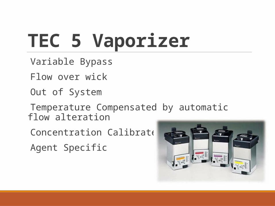
TEC 5 Vaporizer Variable Bypass
Flow over wick
Out of System
Temperature Compensated by automatic flow alteration
Concentration Calibrated
Agent Specific
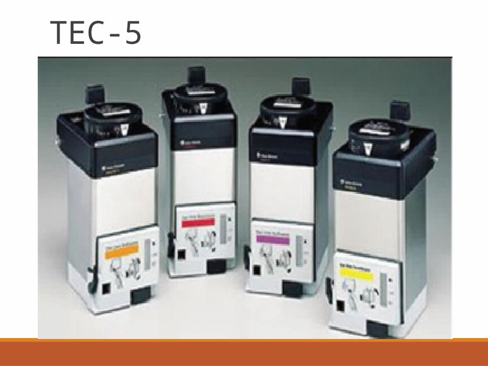
TEC-5
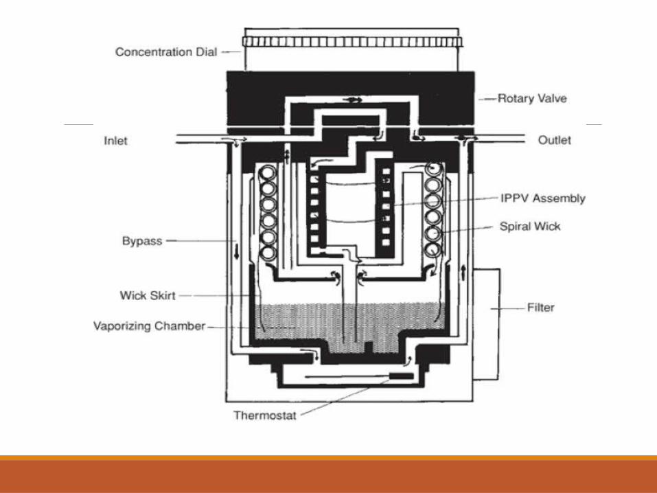
Construction:
The control dial is at the top, the dial must be pushed in before the
vaporizer can be turned on.
At the rear is a locking lever that is connected to the control dial so
that the vaporizer cannot be turned on until it is locked on the
manifold.
At the bottom right front is a sight glass that shows the liquid agent
level in the vaporizing chamber.
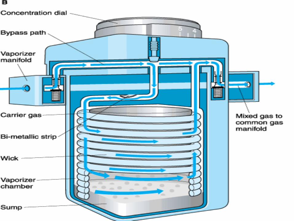
When the dial is turned past zero, inflowing gas is split into
two streams by the rotary valve.
One stream is directed to the vaporizing chamber, the other
through the bypass.
The internal baffle system is designed to keep liquid from
reaching the outlet if the vaporizer is tipped or inverted.
When the concentration dial is in the zero position, all of the gas
from the flowmeters bypasses the vaporizer through the select a
tec bar.
Gas flowing through the bypass flows down one side of the
vaporizer and past the thermostat,which is bimetallic strip in the
base.
As the temperature in the vaporizer decreases,the thermostat
permits less gas flow through the bypass so that more gas passes
through the vaporizing chamber.
From the thermostat, gas flows up the other side of the
vaporizer and near the outlet joins the gas that has passed
through the vaporizing chamber.
Gas flowing to the vaporizing chamber first passes through
the central part of the rotary valve after which it is directed
through a helical channel then past a spiral wick that is in
contact with the wick skirt, which dips into the liquid agent.
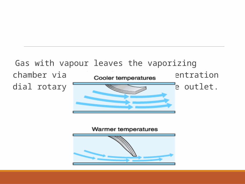
Gas with vapour leaves the vaporizing chamber via a channel in the concentration dial rotary valve and flows to the outlet.
Benefits of TEC 5:
Helical IPPV assemble to minimize effects of positive pressure ventilation.
Volatile Agent capacity increased from 125ml to 300ml
One Handed Dial and more obvious off position
Internal Baffle system designed to prevent liquid from reaching the outlet if vaporizer is tipped or inverted.
Tec 5 vaporizers are available with either of two filling devices:
Keyed system
Funnel fill Funnel Fill System Vaporizer Components The vaporizer filling components include a funnel and cap. When the cap is removed, liquid can be poured into the vaporizing chamber through the funnel.
When the full level is reached, liquid will accumulate in the funnel, and no more liquid will enter the vaporizer.
A funnel-fill vaporizer can be converted to an agent-specific keyed filling system by the addition of an adaptor that screws into the vaporizer filler.
Bottle Component
A color-coded adaptor is available to aid the filling process.
At one end is a connector with a screw thread to match the thread on the bottle and a skirt that extends beyond the screw threads.
It has slots that match the projections on the bottle collar. The adaptor for a different agent than the adaptor is intended for will not screw on either because of different threads or bottle opening size or because the projections will not line up with the slots on the adaptor.
Filling Procedure
The filler cap is removed by turning it counterclockwise. Agent is poured into the filling port until the level reaches the full mark.
The level may fall slightly as the wicks absorb the agent. The filler cap is then securely replaced.
Draining Procedure
To drain the vaporizer, a container is placed under the drain. Removing the filling cap will usually speed drainage.
The mechanism for opening the drain varies with the vaporizer. After draining is complete, the drain plug should be replaced and tightened to minimize leaks.
Keyed Filling System The keyed filling system has been used by many manufacturers for a variety of anesthetic agent
Vaporizer Component The vaporizer filler receptacle (filler socket or block, vaporizer filler unit) permits only the intended bottle adaptor to be inserted.
The receptacle should be sealed when the bottle adaptor is not inserted.
A metal filler block (plug) may be used. There may be a single port for both filling and draining or two ports, the upper one for filling and the lower one for draining .
Bottle Component Each bottle of liquid anesthetic has a color-coded collar attached securely at the neck .
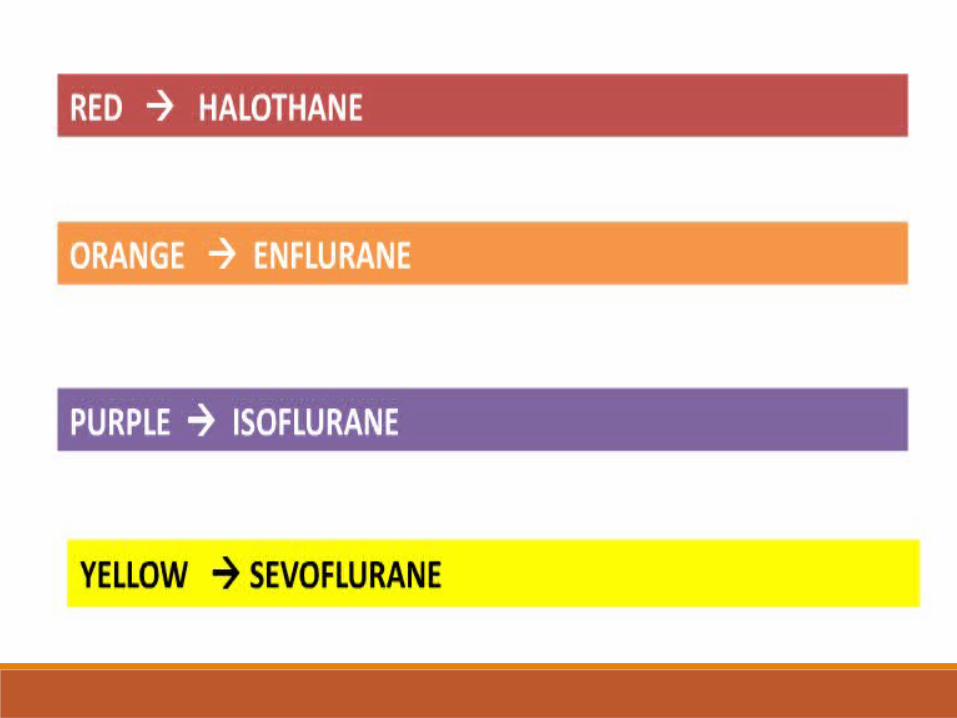
The colors are red for halothane, orange for enflurane, purple for isoflurane, and yellow for sevoflurane.
These colors are also used on the bottle labels. Bottle adaptors are also color coded. At one end, the adaptor has a connector with a screw thread to match the thread on the bottle and a skirt that extends beyond the screw threads and has slots that match the projections on the bottle collar.
At the other end is the male connector that fits into the vaporizer filler receptacle.
Filling To fill a vaporizer, the cap from the bottle is removed, and the bottle adaptor is screwed to the bottle until tight.
If the connection is not tight, the vaporizer may be overfilled or a leak may occur.
The vaporizer should be turned OFF before proceeding further. The plug, if present, is removed. The bottle component is then inserted with the groove matching that on the vaporizer receptacle.
During insertion, the bottle should be below the inlet level. After the filler block is inserted, the retaining device is tightened, and the fill valve (vent) is opened.
The bottle is then held higher than the filler receptacle so that liquid enters the vaporizer
Gentle up-and-down motion may help to clear air bubbles and facilitate filling
Draining
To drain the vaporizer, the bottle adaptor is attached to an appropriate bottle.
In the dual-port filler, the bottom socket is used.
The filler plug is removed, the male adaptor inserted, and the retaining device tightened.
The bottle is held below the receptacle, and the drain (spool) valve is opened.
After the vaporizer is drained, the drain valve is closed, the retaining device loosened, and the bottle adaptor removed. The filler plug should be reinserted and the retaining device tightened
Evaluation of Tec 5 Vaporisers
Accuracy is maximum at a flow of 5lit/min with a dial setting <3%.
Greatest accuracy is between 15˚ and 35˚c
<15˚C output will be less
>35˚C output will be high
Prone to Increase in output due to pumping effect
Carrier Gas Composition effects the output
At low flows output is less if air or nitrous oxide is used as compared to when oxygen is used
Maintenance:
The exterior of the vaporizer may be wiped with a damp cloth.
The vaporizer should be drained every 2 weeks or when the level is low.
The vaporizer should be returned to a service center every 3 years.
Hazards:
If the locking lever is partially loose or the filling port open, there will be a gas leak.
Tilting the vaporizer can result in overfilling
Reversed flow through the vaporizer results in increased output.
References:
1.Dorsch and Dorsch: Understanding Anaesthesia equipment;5th edition.
2.Wards
3.Barash Clinical Anesthesia;7th edition.
4.Chakravarti S, Basu S. Modern anaesthesia vaporizers. Indian J Anaesth 2013;57:464-71.
5.Internet references.

THANK YOU
Related Documents


