Introduction This application note is intended for system designers who require a hardware implementation overview of the development board features. These are power supply, clock management, reset control, boot mode settings, and debug management. This document details how to use the STM32U575xx and STM32U585xx microcontrollers also named STM32U575/585. It describes the minimum hardware resources required to develop an application using these MCUs. Detailed reference design schematics are also given in this document with descriptions of the main components, interfaces, and modes. Getting started with STM32U575/585 MCU hardware development AN5373 Application note AN5373 - Rev 2 - January 2022 For further information contact your local STMicroelectronics sales office. www.st.com

Welcome message from author
This document is posted to help you gain knowledge. Please leave a comment to let me know what you think about it! Share it to your friends and learn new things together.
Transcript

Introduction
This application note is intended for system designers who require a hardware implementation overview of the developmentboard features. These are power supply, clock management, reset control, boot mode settings, and debug management.This document details how to use the STM32U575xx and STM32U585xx microcontrollers also named STM32U575/585. Itdescribes the minimum hardware resources required to develop an application using these MCUs.Detailed reference design schematics are also given in this document with descriptions of the main components, interfaces, andmodes.
Getting started with STM32U575/585 MCU hardware development
AN5373
Application note
AN5373 - Rev 2 - January 2022For further information contact your local STMicroelectronics sales office.
www.st.com

1 General information
This document applies to the STM32U575/585 Arm®-based microcontrollers.
Note: Arm is a registered trademark of Arm Limited (or its subsidiaries) in the US and/or elsewhere.
AN5373General information
AN5373 - Rev 2 page 2/37

2 Power supply management
2.1 Power suppliesThe STM32U575/585 devices require a 1.71 to 3.6 V operating voltage supply (VDD).The independent supplies listed below, can be provided for specific peripherals:• VDD = 1.71 V to 3.6 V
VDD is the external power supply for the I/Os, the internal regulator and the system analog such as reset,power management and internal clocks. VDD is provided externally through the VDD pins.
• VDDA = 1.58 V (COMPs) / 1.6 V (DACs/OPAMPs) / 1.62 V (ADCs) / 1.8 V (VREFBUF) to 3.6 VVDDA is the external-analog power supply for A/D converters, D/A converters, voltage reference buffer,operational amplifiers and comparators. The VDDA voltage level is independent from the VDD voltage. TheVDDA pin must preferably be connected to VDD voltage supply when these peripherals are not used.
Note: In case the VDDA pin is left at high impedance or is tied to VSS, the maximum input voltage that can beapplied on the I/Os with "_a" I/O structure, is reduced (refer to device datasheet for more details).
• VDDSMPS = 1.71 V to 3.6 VVDDSMPS is the external power supply for the SMPS step-down converter. It is provided externally throughthe VDDSMPS pin, and must be connected to the same supply as VDD pin.
• VLXSMPSThe VLXSMPS pin is the switched SMPS step-down converter output.
• VDD11VDD11 is a digital core supply provided through the internal SMPS step-down converter VLXSMPS pin. TwoVDD11 pins are present only on packages with internal SMPS, connected to a total of 4.7 µF (typical)external capacitors. In addition, a 100 nF ceramic capacitor is required for each VDD11 pin.
• VCAPVCAP is the digital core supply, from the internal LDO regulator. VCAP pins (one or two) are present only onpackages with LDO only (no SMPS), connected to a total of 4.7 µF (typical) external capacitor. In addition, a100 nF ceramic capacitor is required for each VCAP pin.
Note: – In case there is two VCAP pins (UFBGA169 package), each pin must be connected to a 2.2 µFcapacitor, for a total around 4.4 µF (maximum 4.7 µF). A 100 nF ceramic capacitor is also required foreach VCAP.
– The SMPS power supply pins (VLXSMPS, VDD11, VDDSMPS, VSSSMPS) are available only onpackages with SMPS. In such packages, the STM32U575/585 devices embed two regulators, oneLDO and one SMPS in parallel, to provide the VCORE supply to digital peripherals. A 4.7 μF totalexternal capacitor and a 2.2 µH coil are required on VDD11 pins. In addition, a 100 nF ceramiccapacitor is required for each VDD11 pin.
– The Flash memory is supplied by VCORE and VDD.• VDDUSB = 3.0 V to 3.6 V
VDDUSB is the external-independent power supply for USB transceivers. The VDDUSB voltage level isindependent from the VDD voltage. The VDDUSB pin must preferably be connected to VDD voltage supplywhen the USB is not used.
Note: In case the VDDUSB pin is left at high impedance or is tied to VSS, the maximum input voltage that can beapplied on the I/Os with "_u" I/O structure, is reduced (refer to device datasheet for more details).
• VDDIO2 = 1.08 V to 3.6 VVDDIO2 is the external power supply for 14 I/Os (port G[15:2]). The VDDIO2 voltage level is independent fromthe VDD voltage, and must preferably be connected to VDD when PG[15:2] are not used.
Note: On small packages, VDDA, VDDIO2 or VDDUSB independent power supplies may not be present as adedicated pin, and are internally bonded to a VDD pin. They are neither not present when the relatedfeatures are not supported on the product.
AN5373Power supply management
AN5373 - Rev 2 page 3/37

• VBAT = 1.65 V to 3.6 V (functionality guaranteed down to VBOR_VBAT minimum value, refer to the productdatasheet)VBAT is the power supply when VDD is not present (through power switch) for RTC, TAMP, external clock32 kHz oscillator, backup registers and optionally backup SRAM.
• VREF-, VREF+VREF+ is the input reference voltage for ADCs and DACs. It is also the output of the internal voltagereference buffer (VREFBUF) when enabled. The VREF+ pin can be grounded when ADC and DAC are notactive.The internal voltage reference buffer supports four output voltages, that are configured with the VRS[2:0]field in VREFBUF_CSR register:– VREF+ around 1.5 V. This requires VDDA ≥ 1.8 V.– VREF+ around 1.8 V. This requires VDDA ≥ 2.1 V.– VREF+ around 2.048 V. This requires VDDA ≥ 2.4 V.– VREF+ around 2.5 V. This requires VDDA ≥ 2.8 V.
VREF- and VREF+ pins are not available on all packages. When not available, they are bonded to VSSAand VDDA pins, respectively.When the VREF+ pin is double-bonded to VDDA in a package, the internal VREFBUF is not available andmust be kept disabled.VREF- must always be equal to VSSA.
The following figures present an overview of the STM32U575/585 devices power supply, depending on the SMPSpresence.
Figure 1. STM32U575xx and STM32U585xx power supply overview (no SMPS)
USB transceiver
Core
SRAM1SRAM2SRAM3SRAM4
Digitalperipherals
LSE crystal 32kHz oscillator Backup registers RCC_BDCR register RTC TAMP BKPSRAM
VDDA domain
Backup domain
Standby circuitry (Wakeup logic, IWDG)
Low-voltage detector
I/O ring VCORE domain
Temperature sensorReset block
3 x PLL Internal RC oscillators
Flash memory
VDDUSB
VDDIO2
VDDIO1
I/O ringPG[15:2]
VDDIO2
VDDAVSSA
VSS
VSS
VDDIO2 domain
VDD domain
VCORE
VSS
VDD
VBAT
VCAP
2 x A/D converters2 x comparators
2 x D/A converters2 x operational amplifiersVoltage reference buffer
LDO regulator
AN5373Power supplies
AN5373 - Rev 2 page 4/37

Figure 2. STM32U575xQ and STM32U585xQ power supply overview (with SMPS)
USB transceiver
Core
SRAM1SRAM2SRAM3SRAM4
Digitalperipherals
LSE crystal 32kHz oscillator Backup registers RCC_BDCR register RTC TAMP BKPSRAM
VDDA domain
Backup domain
Standby circuitry (Wakeup logic, IWDG)
LDO regulator
Low-voltage detector
I/O ring
VCORE domainTemperature sensorReset block
3 x PLL Internal RC oscillators
Flash memory
VDDUSB
VDDIO2
VDDIO1
I/O ringPG[15:2]
VDDIO2
VDDAVSSA
VSS
VSS
VDDIO2 domain
VDD domain
VCORE
VSS
VDD
VBAT
2x VDD11SMPS regulator
Voltage regulator
VLXSMPSVDDSMPSVSSSMPS
2 x A/D converters2 x comparators
2 x D/A converters2 x operational amplifiersVoltage reference buffer
In devices without SMPS, the I/Os and system analog peripherals (such as PLLs and reset block) are fed by VDDsupply source. The VCORE power supply for digital peripherals and memories is generated from the LDO.
Note: If the selected package has the SMPS step-down converter option but the SMPS is not used by the application(and the embedded LDO is used instead), it is recommended to set the SMPS power supply pins as follows:• VDDSMPS and VLXSMPS connected to VSS• VDD11 pins connected to VSS through two (2.2µF + 100 nF) capacitors as in normal mode
2.1.1 Independent analog peripherals supplyTo improve ADC and DAC conversion accuracy and to extend the supply flexibility, the analog peripherals havean independent power supply that can be separately filtered and shielded from noise on the PCB.The voltage supply input of the analog peripherals is available on a separate VDDA pin. An isolated supplyground connection is provided on VSSA pin.The VDDA supply voltage can be different from VDD. After reset, the analog peripherals supplied by VDDA arelogically and electrically isolated and therefore are not available. The isolation must be removed before usingthese peripherals, by setting the ASV bit in the PWR_SVMCR register, once the VDDA supply is present.The VDDA supply can be monitored by analog voltage monitors (AVM), and compared with two thresholds(1.6 V for AVM1 or 1.8 V for AVM2). For more details, refer to the device datasheet and section 'Peripheralvoltage monitoring (PVM)' of the reference manual.When a single supply is used, the VDDA pin can be externally connected to the same VDD supply, through anexternal filtering circuit, in order to ensure a noise-free VDD reference voltage.
AN5373Power supplies
AN5373 - Rev 2 page 5/37

ADC and DAC reference voltage
To ensure a better accuracy on low-voltage inputs and outputs, the user can connect to VREF+ pin, a separatereference voltage lower than VDDA.VREF+ is the highest voltage, represented by the full-scale value, for an analog input (ADC) or output (DAC)signal. VREF+ can be provided either by an external reference or by the VREFBUF, that can output a configurablevoltage: 1.5, 1.8, 2.048 or 2.5 V. The VREFBUF can also provide the voltage to external components through theVREF+ pin.For further information, refer to the device datasheet and section 'Voltage reference buffer (VREFBUF)' of thereference manual.
2.1.2 Independent I/O supply railSome I/Os from port G (PG[15:2]) are supplied from a separate supply rail. The power supply for this rail canrange from 1.08 V to 3.6 V, and is provided externally through the VDDIO2 pin. The VDDIO2 voltage level iscompletely independent from VDD or VDDA.The VDDIO2 pin is available only for some packages (refer to the pinout details in the datasheet for the I/O list).After reset, the I/Os supplied by VDDIO2 are logically and electrically isolated and are therefore not available. Theisolation must be removed before using any I/O from PG[15:2], by setting the IO2SV bit in PWR_SVMR register,once the VDDIO2 supply is present.The VDDIO2 supply is monitored by the VDDIO2 voltage monitoring (IO2VM) and compared with the internalreference voltage (3/4 VREFINT, around 0.9 V).For more details, refer to the device datasheet and section 'Peripheral voltage monitoring (PVM)' of the referencemanual .
2.1.3 Independent USB transceiver supplyThe USB transceivers are supplied from a separate VDDUSB power supply. VDDUSB range is from 3.0 V to 3.6 Vand is completely independent from VDD or VDDA.After reset, the USB features supplied by VDDUSB are logically and electrically isolated, and are therefore notavailable. The isolation must be removed before using the USB OTG peripheral, by setting the USV bit in thePWR_SVMR register, once the VDDUSB supply is present.The VDDUSB supply is monitored by the USB voltage monitoring (UVM) and compared with the internal referencevoltage (VREFINT, around 1.2 V). For more details, refer to the device datasheet and section 'Peripheral voltagemonitoring (PVM)' of the product reference manual .
2.1.4 Battery Backup domainTo retain the content of the backup registers and supply the RTC when VDD is turned off, the VBAT pin can beconnected to an optional backup voltage, supplied by a battery or by another source.The VBAT pin powers RTC, TAMP, LSE oscillator and PC13 to PC15 I/Os, allowing the RTC to operate evenwhen the main power supply is turned off.The backup SRAM is optionally powered through the VBAT pin, when the BREN bit is set in the PWR_BDCR1register.The switch to the VBAT supply is controlled by the power-down reset embedded in the Reset block.
Caution: • During tRSTTEMPO (at VDD startup) or after a PDR (power-down reset) detection, the power switch betweenVBAT and VDD remains connected to VBAT pin.
• During the startup phase, if VDD is established in less than tRSTTEMPO (refer to the datasheet for tRSTTEMPOvalue), and VDD > VBAT + 0.6 V, a current may be injected into VBAT pin through an internal diodeconnected between the VDD pin and the power switch (VBAT). If the power supply/battery connected tothe VBAT pin cannot support this current injection, it is strongly recommended to connect an externallow-drop diode between this power supply and the VBAT pin.
If no external battery is used in the application, it is recommended to connect the VBAT pin externally to VDD witha 100 nF external ceramic decoupling capacitor.
AN5373Power supplies
AN5373 - Rev 2 page 6/37

When the Backup domain is supplied by VDD (analog switch connected to the VDD pin), the following pins areavailable:• PC13, PC14 and PC15, that can be used as GPIO pins• PC13, PC14 and PC15, that can be configured by RTC or LSE (refer to the RTC section of the reference
manual)• Pins listed below, that are configured by TAMP as tamper pins:
– PE3 (TAMP_IN6/TAMP_OUT3)– PE4 (TAMP_IN7/TAMP_OUT8)– PE5 (TAMP_IN8/TAMP_OUT7)– PE6 (TAMP_IN3/TAMP_OUT6)– PC13 (TAMP_IN1/TAMP_OUT2)– PA0 (TAMP_IN2/TAMP_OUT1)– PA1 (TAMP_IN5/TAMP_OUT4)– PC5 (TAMP_IN4/TAMP_OUT5)
Note: • Due to the fact that the power switch can transfer only a limited amount of current (3 mA), the use ofPC13 to PC15 I/Os in output mode is restricted: the speed must be limited to 2 MHz with a maximum loadof 30 pF. These I/Os must not be used as current source (for example to drive a LED).
• Under VDD, TAMP_OUTx pins (PE3, PE4, PE5, PE6, PA0, PA1, PC5) keep the same speed features asthe GPIOs to which they are connected. However, under VBAT, the speed of TAMP_OUTx pins must belimited to 500 kHz.
• The speed of PC13 pin is always limited to 2 MHz, under VDD or under VBAT.
Backup domain access
After a system reset, the Backup domain (RCC_BDCR, PWR_BDCR1, RTC, TAMP and backup registers, plusbackup SRAM) is protected against possible unwanted write accesses. To enable access to the Backup domain,proceed as follows:1. Enable the power interface clock by setting the PWREN bit in RCC_AHB3ENR register.2. Set the DBP bit in PWR_DBPR register to enable access to the Backup domain.
VBAT battery charging
When VDD is present, the external battery can be charged on VBAT through an internal resistance, 5 kΩ or 1.5 kΩ,depending on the VBRS bit in PWR_BDCR2 register.The battery charging is enabled by setting VBE bit in PWR_BDCR2. It is automatically disabled in VBAT mode.
2.1.5 Voltage regulatorThe STM32U575/585 devices embed the following internal regulators in parallel to provide the VCORE supply fordigital peripherals, SRAM1/2/3/4, and embedded Flash memory:• SMPS step-down converter• LDO (linear voltage regulator)They can be selected when the application runs, depending on the application requirements. The SMPS allowsthe power consumption to be reduced, but the noise generated by the SMPS may impact some peripheralbehaviors, requiring the application to switch to LDO when running the peripheral, in order to reach the bestperformances.Except for Standby circuitries and the Backup domain, LDO or SMPS can be used in all voltage scaling ranges(range 1/2/3/4), in all Stop modes (Stop 0/1/2/3) and in Standby with SRAM2 (refer to the 'low-power modesummary' table in the reference manual).The STM32U575/585 devices without SMPS embed only the LDO regulator, that controls all voltage-scalingranges and power modes.
AN5373Power supplies
AN5373 - Rev 2 page 7/37

Dynamic Voltage scaling management
Both LDO and SMPS regulators can provide four different voltages (voltage scaling) and can operate in all Stopmodes. Both regulators also can operate in the following ranges:• Range 1 (1.2 V, 160 MHz), high performance: provides a typical output voltage at 1.2 V and is used when
the system clock frequency is up to 160 MHz.• Range 2 (1.1 V, 110 MHz), medium-high performance: provides a typical output voltage at 1.1 V and is used
when the system clock frequency is up to 110 MHz.• Range 3 (1.0 V, 55 MHz), medium-low power: provides a typical output voltage at 1.0 V and is used when
the system clock frequency is up to 55 MHz.• Range 4 (0.9 V, 25 MHz), low power: provides a typical output voltage at 0.9 V and is used when the system
clock frequency is up to 25 MHz.Voltage scaling is selected through the VOS[1:0] field in PWR_VOSR register.
Caution: The EPOD (embedded power distribution) booster must be enabled and ready before increasing the systemclock frequency above 50 MHz in Range 1 and Range 2 (refer to reference manual for sequences to switchbetween voltage scaling ranges).
2.1.6 Power supply for I/O analog switchesSome I/Os embed analog switches for both analog peripherals (ADCs, COMPs, DACs) and TSC (touchsensing controller) functions. These switches are by default supplied by VDDA, but can be supplied by aVDDA voltage booster or by VDD, depending on the configuration of ANASWVDD and BOOSTEN bits inSYSCFG_CFGR1 register.It is recommended to supply the I/O switches with the highest voltage value between VDDA, VDDA boosterand VDD.
Note: If possible, select VDDA or VDDA booster rather than VDD, as they are often less noisy.The analog switches for TSC function are supplied by VDD.
2.2 Power supply schemesThe device is powered by a stabilized VDD power supply as described below:
• VDD pins must be connected to VDD with external decoupling capacitors: a 10 μF (typical value, 4.7 µFminimum) single tantalum or ceramic capacitor for the package, and a 100 nF ceramic capacitor for eachVDD pin.
• VDD11 pins are present only on packages with SMPS. The SMPS step-down converter requires a 2.2 μH(typical) external ceramic coil connected between VLXSMPS and VDD11 pins. In addition, two 2.2 μFcapacitors on VDD11 pins are connected to the VSSSMPS pin. In addition, a 100 nF ceramic capacitor isrequired to be connected between each VDD11 pin and the ground.
• The VCAP pin is present only on standard packages (without SMPS). It requires a 4.7 µF (typical) externaldecoupling capacitor connected to VSS. If there are two VCAP pins (UFBGA169 package), each VCAP pinmust be connected to a 2.2 µF (typical) capacitor (for a maximum of 4.7 µF). In addition, a 100 nF ceramiccapacitor is required to be connected between each VCAP pin and the ground.
• The VDDA pin must be connected to two external decoupling capacitors: 100 nF ceramic and 1 μF tantalumor ceramic.Additional precautions can be taken to filter digital noise: VDDA can be connected to VDD through a ferritebead.
• VDDIO2 pins must be connected to an external decoupling capacitors of 4.7 µF, tantalum or ceramic. Inaddition, each VDDIO2 pin requires an external 100 nF ceramic capacitor.
• VDDUSB pin must be connected to an external 100 nF ceramic capacitor.• The VREF+ pin can be provided by an external voltage reference. In this case, an external 100 nF + 1 μF
tantalum or ceramic capacitor must be connected on this pin.It can also be provided internally by the VREFBUF. In this case, an external 100 nF + 1 μF (typical) capacitormust be connected on this pin.
AN5373Power supply schemes
AN5373 - Rev 2 page 8/37

• The VBAT pin can be connected to an external battery to preserve the content of the Backup domain:– When VDD is present, the external battery can be charged on VBAT through a 5 kΩ or 1.5 kΩ internal
resistor. In this case, the user can insert a capacitor according to the expected discharging time (1 µFis recommended).
– If no external battery is used in the application, it is recommended to connect the VBAT pin to VDD witha 100 nF external ceramic decoupling capacitor.
• The VDDUSB pin when present in a package can be connected to a ceramic capacitor of 100 nF.The figures below details the power supply schemes for packages with and without SMPS.
Figure 3. Power supply scheme for STM32U575x and STM32U585x (without SMPS)
VDDIO2
VDD
Leve
l shi
fter
I/Ologic
Kernel logic(CPU, digital
and memories)
Backup circuitry(LSE, RTC, TAMPbackup registers, backup SRAM)
IN
OUT
LDO regulator
GPIOs
1.65 – 3.6 V
IN
OUT
GPIOs
n x 100 nF+ 1 x 10 µF
m x 100 nF
Leve
l shi
fter
I/Ologic
+ 4.7 µF
m x VDDIO2
m x VSS
n x VSS
n x VDD
VBAT
VCORE
Power switch
VDDIO2
VDDIO1
ADCs/DACs/
OPAMPs/COMPs/
VREFBUF
VREF+
VREF-
VDDA
100 nF+1 µF
VDDA
VSSA
VREF
100 nF+ 1 µF
VCORE
4.7 µF
VCAP
VDDUSB3.3 V
100 nF
100 nF
Caution: If there are two VCAP pins (UFBGA169 package), each pin must be connected to a 2.2 µF (typical) capacitor(for a total around 4.4 µF).
AN5373Power supply schemes
AN5373 - Rev 2 page 9/37

Figure 4. Power supply scheme for STM32U575xQ and STM32U585xQ (with SMPS)
VDDIO2
VDD
Kernel logic (CPU, digital
and memories)
Leve
l shi
fter
IOlogic
Backup circuitry(LSE, RTC, TAMP,backup registers, backup SRAM)
IN
OUT
GPIOs
1.65 – 3.6 V
IN
OUT
GPIOs
n x 100 nF+ 10 µF
m x100 nF
Leve
l shi
fter
IOlogic
+ 4.7 µF
m x VDDIO2
m x VSS
n x VSS
n x VDD
VBAT
VCORE
Power switch
VDDIO2
VDDIO1
ADCs/DACs/
OPAMPs/COMPs/
VREFBUF
VREF+
VREF-
VDDA
100 nF+ 1 µF
VDDA
VSSA
VREF
100 nF+ 1 µF
VSSSMPS
2 x VDD11
VLXSMPS
VDDSMPSVDD
2.2 µH
2 x 2.2 µF
10 µF
SMPS ON
SMPS OFF
LDO
SMPS
VDDUSB3.3 V
100 nF
Voltage regulator
2 x 100 nF
Note: • SMPS and LDO regulators provide, in a concurrent way, the VCORE supply depending on applicationrequirements. However, only one of them is active at the same time. When SMPS is active, it feeds theVCORE on the two VDD11 pins provided through the SMPS VLXSMPS output pin. A 2.2 µH coil and a2.2 μF capacitor on each VDD11 pin are then required. When LDO is active, it provides the VCORE andregulates it using the same decoupling capacitors on VDD11 pins.
• It is required to add a decoupling capacitor of 100 nF near each VDD11 pin/ball.
AN5373Power supply schemes
AN5373 - Rev 2 page 10/37

2.3 Power supply sequence between VDDA, VDDUSB, VDDIO2, and VDD
2.3.1 Power supply isolationThe devices feature a powerful reset system that ensures the main power supply (VDD) has reached a validoperating range before releasing the MCU reset.This reset system is also in charge of isolating the independent power domains: VDDA, VDDUSB, VDDIO2, andVDD. This reset system is supplied by VDD and is not functional before VDD reaches a minimal voltage (1 V inworse-case conditions).In order to avoid leakage currents between the available supplies and VDD (or ground), VDD must be provided firstto the MCU and released last with tolerance during power down (refer to Section 2.3.3 ).
2.3.2 General requirementsDuring power-up and power-down phases, the following power sequence requirements must be respected:• When VDD is below 1 V, other power supplies (VDDA, VDDIO2 and VDDUSB) must remain below
VDD + 300 mV.• When VDD is above 1 V, all power supplies are independent.
Figure 5. Power-up/power-down sequence
0.3
1
VDD_MIN
VDD_MAX
Operating modePower-on Power-down time
V
VDDX(1)
VDD
Invalid supply area
VDDX < VDD + 300 mV
VDDX independent from VDD
Transient phase with energy below 1 mJ
(1) VDDX refers to any power supply among VDDA, VDDIO2 and VDDUSB.
Note: VBAT is an independent supply and has no constraint versus VDD. All power supply rails can be tied together.
2.3.3 Particular conditions during power-down phaseDuring the power-down phase, VDD can temporarily become lower than other supplies only if the energy providedto the MCU remains below 1 mJ. This allows external decoupling capacitors to be discharged with different timeconstants during the power-down transient phase (refer to Figure 5).VDDX (VDDA, VDDIO2, or VDDUSB) power rails must be switched off before VDD.
Note: During the power-down transient phase, VDDX can remain temporarily above VDD (refer to Figure 5).
AN5373Power supply sequence between VDDA, VDDUSB, VDDIO2, and VDD
AN5373 - Rev 2 page 11/37

Example of computation of the energy provided to the MCU during the power-down phase
If the sum of decoupling capacitors on VDDX is 10 μF and VDD drops below 1 V while VDDX is still at 3.3 V, theenergy remaining in the decoupling capacitors is:E = ½ C x V2 = ½ x 10-5 x 3.32 = 0.05 mJThe energy remaining in the decoupling capacitors is below 1 mJ, so it is acceptable for the MCU to absorb it.
2.4 Reset and power-supply supervisor
2.4.1 Brownout reset (BOR)The devices have a Brownout reset (BOR) circuitry. The BOR is active in all power modes except Shutdownmode, and cannot be disabled. The BOR monitors the Backup domain supply voltage, that is VDD when present,VBAT otherwise.Five BOR thresholds can be selected through option bytes.During power-on, the BOR keeps the device under reset until the supply voltage VDD reaches the specified VBORxthreshold. When VDD drops below the selected threshold, a device reset is generated. When VDD is above theVBORx upper limit, the device reset is released and the system can start.For more details on the Brownout reset thresholds, refer to the electrical characteristics section in the datasheet.
Figure 6. Brownout reset waveform
Hysteresis
Reset
VDD
VBOR (rising edge)
VBOR (falling edge)
tRSTTEMPO
temporization(1)
(1) The reset temporization tRSTTEMPO is present only for the BOR lowest threslhold (VBOR0)
2.4.2 System resetA system reset sets all registers to their reset values except the reset flags in RCC_CSR register and theregisters in the Backup domain.A system reset is generated when one of the following events occurs (refer to reference manual for more details):• a low level on the NRST pin (external reset)• a window watchdog event (WWDG reset)• an independent watchdog event (IWDG reset)• a software reset• a low-power mode security reset• an option byte loader reset• a Brownout resetThese sources act on the NRST pin, that is always kept low during the delay phase. The reset service routinevector is selected via the boot option bytes.The system reset signal provided to the device is output on the NRST pin. The pulse generator guarantees aminimum reset pulse duration of 20 μs for each internal reset source. In case of an external reset, the reset pulseis generated while the NRST pin is asserted low.
AN5373Reset and power-supply supervisor
AN5373 - Rev 2 page 12/37

In case of an internal reset, the internal pull-up RPU is deactivated in order to save the power consumptionthrough the pull-up resistor.
Figure 7. Simplified diagram of the reset circuit
External reset
VDD
RPU
WWDG reset
Software resetLow-power manager reset
IWDG reset
Option byte loader reset
Pulse generator
(min 20 μs)
NRST
System reset
Filter
BOR
2.4.3 Backup domain resetA Backup domain reset is generated when one of the following events occurs:• a software reset, triggered by setting the BDRST bit in RCC_BDCR register• a VDD or VBAT power-on, if both supplies have previously been powered off
A Backup domain reset only affects the LSE oscillator, the RTC and TAMP, the backup registers, the backupSRAM, and the RCC_BDCR and PWR_BDCR1 registers.
AN5373Reset and power-supply supervisor
AN5373 - Rev 2 page 13/37

3 Packages
3.1 Package summaryThe package selection must take into account the constraints that are strongly dependent upon the application.The list below summarizes the most frequent ones:• Amount of interfaces required: Some interfaces may not be available on some packages. Some interfaces
combinations may not be possible on some packages.• PCB technology constrains: Small pitch and high-ball density may require more PCB layers and
higher‑class PCB.• Package height• PCB available area• Noise emission or signal integrity of high-speed interfaces• Smaller packages usually provide better signal integrity. This is further enhanced as small-pitch and high-ball
density requires multilayer PCBs that allow better supply/ground distribution.• Compatibility with other devices
Table 1. Package summary for STM32U575/585
Package Size (mm)(1) Pitch (mm) Height (mm)(2) Without SMPS With SMPS
UFQFN48 7 x 7 0.5 0.6 X X
LQFP48 7 x 7 0.5 1.6 X X
LQFP64 10 x 10 0.5 1.6 X X
WLCSP90 4.20 x 3.95 0.4 0.59 - X
LQFP100 14 x 14 0.5 1.6 X X
UFBGA132 7 x 7 0.5 0.6 X X
LQFP144 20 x 20 0.5 1.6 X X
UFBGA169 7 x 7 0.5 0.6 X X
1. Body size, excluding pins for LQFP.2. Maximum value.
AN5373Packages
AN5373 - Rev 2 page 14/37

3.2 Pinout summary
Table 2. Pinout summary for STM32U575/585
Pin name
STM32U575xx and STM32U585xx
packages (without SMPS)
STM32U575xQ and STM32U585xQ
packages (with SMPS)LQ
FP48
UFQ
FPN
48
LQFP
64
LQFP
100
UFB
GA
132
LQFP
144
UFB
GA
169
LQFP
48 S
MPS
UFQ
FPN
48 S
MPS
LQFP
64 S
MPS
WLC
SP90
SM
PS
LQFP
100
SMPS
UFB
GA
132
SMPS
LQFP
144
SMPS
UFB
GA
169
SMPS
Specific I/Os
PC14-OSC32_IN X(1) X X X X X X X X X X X X
PC15-OSC32_OUT X X X X X X X X X X X X X
PH0-OSC_IN X X X X X X X X X X X X X
PH1-OSC_OUT X X X X X X X X X X X X X
System pins
NRST X X X X X X X X X X X X X
PH3-BOOT0 X X X X X X X X X X X X X
Power pins
VBAT X X X X X X X X X X X X X
VDDUSB -(2) X X X X X - X X X X X X
VSSA(3) o o X o X o o o o o o o o
VREF- o o X o X o o o o o o o o
VREF+(4) o o X o X X o o X X X X X
VDDA o o X o X X o o X X X X X
VDDIO2 - - - X X X - - X - X X X
VDD11 - - - - - - X X X X X X X
VDDSMPS - - - - - - X X X X X X X
VSSSMPS - - - - - - X X X X X X X
VLXSMPS - - - - - - X X X X X X X
VCAP X X X X X X - - - - - - -
Number of VDD 3 3 5 6 9 10 3 3 4 5 6 9 10
Number of VSS 3 4 5 6 11 11 3 3 4 5 6 11 11
1. 'X' means the pin is present.2. '-' means the pin is absent.3. 'o' means that VSSA and VREF- are internally connected and available on a single pin.4. 'o' means that VDDA and VREF+ are internally connected and available on a single pin.
AN5373Pinout summary
AN5373 - Rev 2 page 15/37

Caution: STM32U575/585 packages with and without SMPS are not compatible, in almost all power supply pins ofthe above table.Example: VDDIO2 is the pin number 130 on SMPS package. Pin 130 on the package without SMPS is mappedto a VSS pin. It means the system is short-circuited when a legacy package is mounted on an SMPS socket.
AN5373Pinout summary
AN5373 - Rev 2 page 16/37

4 Clocks
The following clock sources can be used to drive the system clock (SYSCLK):• HSI16: high-speed internal 16 MHz RC oscillator clock• MSIS: multi-speed internal RC oscillator clock• HSE: high-speed external crystal or clock, from 4 to 50 MHz• PLL1 clockThe MSIS is used as system clock source after startup from reset, configured at 4 MHz.The devices have the following additional clock sources:• MSIK: multi-speed internal RC oscillator clock used for peripherals kernel clocks• LSI: 32 kHz low-speed internal RC that drives the independent watchdog and optionally the RTC used for
auto-wakeup from Stop and Standby modes• LSE: 32.768 kHz low-speed external crystal or clock that optionally drives the real-time clock (rtc_ck)• HSI48: internal 48 MHz RC that potentially drives the OTG FS, the SDMMC and the RNG• SHSI: secure high-speed internal RC that drives the secure AES (SAES).• PLL2 and PLL3 clocksEach clock source can be switched on or off independently when it is not used, to optimize power consumption.Several pre-scalers can be used to configure the AHB and the APB frequencies domains with a maximumfrequency of 160 MHz.
4.1 HSE clockThe high-speed external clock signal (HSE) can be generated from the following clock sources:• HSE external crystal/ceramic resonator• HSE user external clock that feeds OSC_IN pinThe resonator and the load capacitors must be placed as close as possible to the oscillator pins in orderto minimize output distortion and startup stabilization time. The loading capacitance values must be adjustedaccording to the selected oscillator.
Table 3. HSE/LSE clock sources
Clock source Hardware configuration
External clock OSC_IN OSC_OUT
GPIO
External souce
Crystal/ceramic resonators
OSC_OUTOSC_IN
CL1 CL2
Load capacitors
CL1 and CL2 values depend on the quartz. Refer to the application note Oscillatordesign guide for STM8AF/AL/S and STM32 microcontrollers (AN2867) for more
details.
AN5373Clocks
AN5373 - Rev 2 page 17/37

4.1.1 External crystal/ceramic resonator (HSE crystal)The 4 to 50 MHz external oscillator has the advantage of producing a very accurate rate on the main clock.The associated hardware configuration is shown in Table 3. Refer to the electrical characteristics section of thedatasheet for more details.
4.1.2 External source (HSE bypass)In this mode, an external clock source must be provided, with a frequency up to 50 MHz. The external clock signal(square, sinus or triangle) with ~40 to 60 % duty cycle depending on the frequency (refer to the datasheet), mustdrive the OSC_IN pin while the OSC_OUT pin can be used as a GPIO (see Table 3).
Note: For details on pin availability, refer to the pinout section of the datasheet. To minimize the consumption, thesquare signal is recommended.
4.2 HSI16 clockThe HSI16 clock signal is generated from an internal 16 MHz RC oscillator. The HSI16 RC oscillator providesa clock source at low cost (no external components). It also has a faster startup time than the HSE crystaloscillator. However, even with calibration, the frequency is less accurate than an external crystal oscillator orceramic resonator.The HSI16 clock can be used as a backup clock source (auxiliary clock) if the HSE crystal oscillator fails.For more details, refer to section 'Clock security system (CSS)' in the reference manual.
4.3 MSI (MSIS and MSIK) clocksThe MSI is made of four internal RC oscillators: MSIRC0 (48 MHz), MSIRC1 (4 MHz), MSIRC2 (3.072 MHz) andMSIRC3 (400 kHz). Each oscillator feeds a prescaler providing a division by 1, 2, 3 or 4.Two output clocks are generated from these divided oscillators:• MSIS, that can be selected as system clock• MSIK, that can be selected by some peripherals as kernel clockMSIS and MSIK frequency range can be adjusted by software, by using respectively the MSISRANGE [3:0] andMSIKRANGE [3:0] fields in RCC_ICSCR1 register, with MSIRGSEL = 1. Sixteen frequency ranges are available,generated from the four internal RCs (see the reference manual for more details).The MSI clock can also be used as a backup clock source (auxiliary clock) if the HSE crystal oscillator fails (seesection' Clock security system (CSS)' in the reference manual).The MSI oscillator provides a low-cost (no external components) low-power clock source. In addition, when usedin PLL‑mode with the LSE, the MSI provides a very accurate clock source that can be used by the USB OTG-FSperipheral, and feeds the PLL to run the system at the maximum speed 160 MHz.
Hardware auto calibration with LSE (PLL-mode)
When a 32.768 kHz external oscillator is present in the application, either MSIS or MSIK can be configured in aPLL-mode. This mode is enabled as follows:• for MSIS: by setting the MSIPLLEN bit to 1 in RCC_CR register• for MSIK: by setting the MSIPLLEN bit to 0 in RCC_CR registerIn case MSIS and MSIK ranges are generated from the same MSIRC source, the PLL-mode is applied on bothMSIS and MSIK. When configured in PLL-mode, the MSIS or MSIK automatically calibrates itself thanks to theLSE. This mode is available for all MSI frequency ranges. At 48 MHz, the MSIK in PLL-mode can be used for theUSB OTG-FS device, avoiding the need of an external high-speed crystal.For more details on how to measure the MSI frequency variation, refer to section Internal/external clockmeasurement with TIM15/TIM16/TIM17 in the reference manual.
4.4 LSE clockThe LSE crystal is a 32.768 kHz low-speed external crystal or ceramic resonator (see Table 3). It provides alow-power but highly-accurate clock source to the RTC (real-time clock) peripheral for clock/calendar or othertiming functions.The crystal oscillator driving strength can be changed at runtime using the LSEDRV[1:0] bits in the RCC_BDCRregister, to obtain the best compromise between robustness and short start-up time on one side and low-power-consumption on the other side.
AN5373HSI16 clock
AN5373 - Rev 2 page 18/37

External source (LSE bypass)
In this mode, an external clock source must be provided, with a frequency up to 1 MHz. The external clock signal(square, sinus or triangle) with ~50 % duty cycle, must drive the OSC32_IN pin while the OSC32_OUT pin can beused as GPIO (see Table 3).
AN5373LSE clock
AN5373 - Rev 2 page 19/37
5 Boot configuration
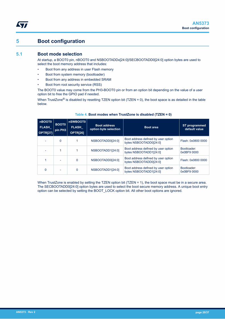
5.1 Boot mode selectionAt startup, a BOOT0 pin, nBOOT0 and NSBOOTADDx[24:0]/SECBOOTADD0[24:0] option bytes are used toselect the boot memory address that includes:• Boot from any address in user Flash memory• Boot from system memory (bootloader)• Boot from any address in embedded SRAM• Boot from root security service (RSS)The BOOT0 value may come from the PH3-BOOT0 pin or from an option bit depending on the value of a useroption bit to free the GPIO pad if needed.When TrustZone® is disabled by resetting TZEN option bit (TZEN = 0), the boot space is as detailed in the tablebelow.
Table 4. Boot modes when TrustZone is disabled (TZEN = 0)
nBOOT0
FLASH_
OPTR[27]
BOOT0
pin PH3
nSWBOOT0
FLASH_
OPTR[26]
Boot addressoption‑byte selection Boot area ST programmed
default value
- 0 1 NSBOOTADD0[24:0] Boot address defined by user optionbytes NSBOOTADD0[24:0] Flash: 0x0800 0000
- 1 1 NSBOOTADD1[24:0] Boot address defined by user optionbytes NSBOOTADD1[24:0]
Bootloader:0x0BF9 0000
1 - 0 NSBOOTADD0[24:0] Boot address defined by user optionbytes NSBOOTADD0[24:0] Flash: 0x0800 0000
0 - 0 NSBOOTADD1[24:0] Boot address defined by user optionbytes NSBOOTADD1[24:0]
Bootloader:0x0BF9 0000
When TrustZone is enabled by setting the TZEN option bit (TZEN = 1), the boot space must be in a secure area.The SECBOOTADD0[24:0] option bytes are used to select the boot secure memory address. A unique boot entryoption can be selected by setting the BOOT_LOCK option bit. All other boot options are ignored.
AN5373Boot configuration
AN5373 - Rev 2 page 20/37

The table below details the boot modes when the TrustZone is enabled.
Table 5. Boot modes when TrustZone is enabled (TZEN = 1)
BOOT_
LOCK
nBOOT0
FLASH_
OPTR[27]
BOOT0
pin
PH3
nSWBOOT0
FLASH_
OPTR[26]
RSScommand
Boot addressoption‑byte selection Boot area
STprogrammeddefault value
0
- 0 1 0 SECBOOTADD0[24:0]
Secure bootaddress defined byuser option bytesSECBOOTADD0[24:0]
Flash:0x0C00 0000
- 1 1 0 N/A RSS RSS:0x0FF8 0000
1 - 0 0 SECBOOTADD0[24:0]
Secure bootaddress defined byuser option bytesSECBOOTADD0[24:0]
Flash:0x0C00 0000
0 - 0 0 N/A RSS RSS:0x0FF8 0000
- - - ≠ 0 N/A RSS RSS:0x0FF8 0000
1 - - - - SECBOOTADD0[24:0]
Secure bootaddress defined byuser option bytesSECBOOTADD0[24:0]
Flash:0x0C00 0000
5.2 Embedded bootloader and RSSThe embedded bootloader is located in the system memory and programmed by ST during production. It is usedto reprogram the Flash memory by using the following serial interfaces:• USART: USART1 on pins PA9/PA10, USART2 on pins PA2/PA3, USART3 on pins PC10/PC11• I2C: I2C1 on pins PB6/PB7, I2C2 on pins PB10/PB11, I2C3 on pins PC0/PC1• SPI: SPI1 on pins PA4/PA5/PA6/PA7, SPI2 on pins PB12/PB13/PB14/PB15, SPI3 on pins PB5/PG9/PG10/
PG12• FDCAN1 on pins PB8/PB9• USB in device mode through the DFU (device firmware upgrade) interface, on pins PA11/PA12For further details on STM32 bootloader, refer to the application note STM32 microcontroller system memory bootmode (AN2606).The RSS (root secure services) are embedded in a Flash memory area named secure information block,programmed during ST production.The RSS enables for example the SFI (secure firmware installation) using the RSS extension firmware(RSSe SFI). This feature allows the customers to protect the confidentiality of the firmware to be provisioned intothe STM32 device when the production is subcontracted to a third party. Refer to the application note Overviewsecure firmware install (SFI) (AN4992).The RSS is available on all devices, after enabling the TrustZone through the TZEN option bit.
AN5373Embedded bootloader and RSS
AN5373 - Rev 2 page 21/37

6 Debug management
The serial wire/JTAG debug port (SWJ-DP) is an Arm standard CoreSight™ debug port.The host/target interface is the hardware equipment that connects the host to the application board. This interfaceis made of three components: a hardware debug tool, a serial-wire connector and a cable connecting the host tothe debug tool.The figure below shows the connection of the host to a development board.
Figure 8. Host-to-board connection
STM32 board
Host PC Power supply
JTAG/serial-wire connectorDebug tool
The Nucleo demonstration board embeds the debug tools (ST-LINK), so it can be directly connected to the PCthrough an USB cable.
6.1 SWJ-DP (serial-wire and JTAG debug port)The SWJ-DP combines:• a JTAG‑DP that provides a 5-pin standard JTAG interface to the AHP-AP port• a SW-DP that provides a 2-pin (clock + data) interface to the AHP-AP portIn the SWJ-DP, the two JTAG pins of the SW-DP are multiplexed with some of the five JTAG pins of the JTAG-DP.
Note: All SWJ-DP port I/Os can be reconfigured to other functions by software, but debugging is no longer possible.
6.2 Pinout and debug port pinsThe devices are offered in various packages with different numbers of available pins. As a result, somefunctionality related to the pin availability may differ from one package to another.
6.2.1 SWJ-DP pinsFive pins are used as outputs for the SWJ-DP, as alternate functions of the GPIOs (general-purpose I/Os). Thesepins, detailed in the table below, are available on all packages.
Table 6. Debug port pin assignment
SWJ-DP pinJTAG debug port SW debug port
Pin assignmentType Description Type Debug assignment
JTMS/SWDIO Input JTAG test mode selection Input/Output Serial‑wire data input/output PA13
JTCK/SWCLK Input JTAG test clock Input Serial‑wire clock PA14
JTDI Input JTAG test data input - - PA15
JTDO/TRACESWO Output JTAG test data output - TRACESWO if asynchronous traceis enabled PB3
JNTRST Input JTAG test nReset - - PB4
AN5373Debug management
AN5373 - Rev 2 page 22/37

6.2.2 Flexible SWJ-DP pin assignmentAfter reset (SYSRESETn or PORESETn), all five pins used for the SWJ-DP are assigned as dedicated pins thatare immediately usable by the debugger host.
Note: The trace outputs are not assigned except if explicitly programmed by the debugger host.The table below shows the different possibilities for releasing some pins (see the reference manual for moredetails).
Table 7. SWJ-DP I/O pin availability
Available debug ports
SWJ-DP I/O pin assigned
PA13 /
JTMS/
SWDIO
PA14 /
JTCK/
SWCLK
PA15 /
JTDI
PB3 /
JTDO
PB4/
JNTRST
Full SWJ‑DP (JTAG‑DP + SW‑DP)
Reset stateX X X X X
Full SWJ‑DP (JTAG‑DP + SW‑DP) but without JNTRST X X X X
-JTAG-DP disabled and SW-DP enabled X X -
JTAG-DP disabled and SW-DP disabled Released
6.2.3 Internal pull-up and pull-down resistors on JTAG pinsThe JTAG input pins must not be floating since they are directly connected to flip-flops that control the debugmode features. Special care must be taken with the SWCLK/TCK pin that is directly connected to the clock ofsome of these flip-flops.To avoid any uncontrolled I/O levels, the devices embed the following internal resistors on the JTAG input pins:• JNTRST: internal pull-up• JTDI: internal pull-up• JTMS/SWDIO: internal pull-up• TCK/SWCLK: internal pull-downOnce a JTAG I/O is released by the user software, the GPIO controller takes the control again, and the softwarecan then use these I/Os as standard GPIOs. The reset states of the GPIO control registers put the I/Os in thefollowing equivalent states:• JNTRST: input pull-up• JTDI: input pull-up• JTMS/SWDIO: input pull-up• JTCK/SWCLK: input pull-down• JTDO: input floating
Note: The JTAG IEEE standard recommends to add pull-up resistors on TDI, TMS and nTRST, but there is no specialrecommendation for TCK. However, for the devices, an integrated pull-down resistor is used for JTCK. Havingembedded pull-up and pull-down resistors removes the need to add external resistors.
AN5373Pinout and debug port pins
AN5373 - Rev 2 page 23/37

6.2.4 SWJ-DP connection with standard JTAG connectorThe figure below shows the connection between the device and a standard JTAG connector.
Figure 9. JTAG connector implementation
VDD
STM32U5 MCU
nJTRSTJTDI
JTMS/SWDIOJTCK/SWCLK
JTDOnRST
(1) VTREF(3) nTRST(5) TDI(7) TMS(9) TCK(11) RTCK
(15) nSRST
(19) DBGACK
10 kΩ
(2)
(4)
(6)
(8)
(10)
(12)
(14)
(16)
(18)
(20)
JTAG connector
10 kΩ10 kΩ
(17) DBGRQ
(13) TDO
VDD
VSS
Connector 2 x 10
6.3 Serial-wire debug (SWD) pin assignmentThe same SWD pin assignment, detailed in the table below, is available on all packages.
Table 8. SWD port pins
SWD pinSWD port
Pin assignmentType Debug assignment
SWDIO Input/Output Serial-wire data input/output PA13
SWCLK Input Serial-wire clock PA14
After reset, the pins used for the SWD are assigned as dedicated pins that can be immediately used by thedebugger host.However, the MCU offers the possibility to disable the SWD, therefore releasing the associated pins for GPIO use.For more details on how to disable SWD port, refer to the section 'I/O pin alternate function multiplexer andmapping' of the reference manual.
6.3.1 Internal pull-up and pull-down on SWD pinsOnce the SWD I/O is released by the user software, the GPIO controller takes control of it. The reset states of theGPIO control registers put the I/Os in the equivalent states:• SWDIO: alternate function pull-up• SWCLK: alternate function pull-downHaving embedded pull-up and pull-down resistors removes the need to add external resistors.
AN5373Serial-wire debug (SWD) pin assignment
AN5373 - Rev 2 page 24/37

6.3.2 SWD port connection with standard SWD connectorThe figure below shows the connection between the device and a standard SWD connector.
Figure 10. SWD connector implementation
CN1 NRST
SWCLK/PA14
SWDIO/PA13
SWD connector
VDD
10987654321
STM32U5 device
AN5373Serial-wire debug (SWD) pin assignment
AN5373 - Rev 2 page 25/37

7 Recommendations
7.1 PCB (printed circuit board)For technical reasons, it is best to use a multilayer PCB, with a separate layer dedicated to ground (VSS) andanother dedicated to the VDD supply.This provides a good decoupling and a good shielding effect. For many applications, economical reasons prohibitthe use of this type of board. In this case, the major requirement is to ensure a good structure for ground andpower supply.
7.2 Component positionA preliminary layout of the PCB must separate circuits into different blocks:• high-current circuits• low-voltage circuits• digital component circuits• circuits separated according to their EMI contribution, in order to reduce noise due to cross-coupling
on the PCB
7.3 Ground and power supplyThe following rules related to grounding must be respected:• Ground every block (noisy, low-level sensitive, digital or others) individually.• Return all grounds to a single point.• Avoid loops (or ensure they have a minimum area).In order to improve analog performance, the user must use separate supply sources for VDD and VDDA, and placethe decoupling capacitors as close as possible to the device.The power supplies (VSS, VDD, VSSA, VDDA, VDDUSB, VDDIO2 or VDDSMPS) must be implemented close to theground line to minimize the area of the supplies loop. This is due to the fact that the supply loop acts as anantenna, and acts as the main transmitter and receiver of EMI. All component-free PCB areas must be filled withadditional grounding to create a kind of shielding (especially when using single‑layer PCBs).
7.4 DecouplingAll power-supply and ground pins must be properly connected to the power supplies. These connections(including pads, tracks and vias) must have the lowest possible impedance. This is typically achieved with thicktrack widths and, preferably, the use of dedicated power-supply planes in multilayer PCBs.In addition, each power supply pair must be decoupled with filtering ceramic capacitors (100 nF) and a tantalumor ceramic capacitor of about 10 μF, connected in parallel on the device.Some packages use a common VSS pin for several VDD pins, instead of a pair of power pins (one VSS for eachVDD). In that case, the capacitors must be between each VDD pin and the common VSS pin. These capacitorsmust be placed as close as possible to, or below the appropriate pins on the underside of the PCB. Typical valuesare 10 to 100 nF, but exact values depend on the application needs.
AN5373Recommendations
AN5373 - Rev 2 page 26/37

The figure below shows the typical layout of such a VDD/VSS pin pair.
Figure 11. Typical layout for VDD/VSS pin pair
Via to VDD Via to VSS
VSSVDD
STM32
7.5 Other signalsWhen designing an application, the EMC performance can be improved by closely studying the following:• Signals for which a temporary disturbance affects the running process permanently (it is the case for
interrupts and handshaking strobe signals but not the case for LED commands)For these signals, a surrounding ground trace, shorter lengths, and the absence of noisy and sensitivetraces nearby (crosstalk effect) improve EMC performance.For digital signals, the best possible electrical margin must be reached for the two logical states. SlowSchmitt triggers are recommended to eliminate parasitic states.
• Noisy signals (example: clock)• Sensitive signals (example: high impedance)
7.6 Unused I/Os and featuresAll microcontrollers are designed for a variety of applications and often a particular application does not use100 % of the MCU resources.To increase the EMC performance and avoid extra power consumption, the unused features of the device mustbe disabled and disconnected from the clock tree, as follows:• The unused clock source must be disabled.• The unused I/Os must not be left floating.• The unused I/O pins must be configured as analog input by software, and must be connected to a fixed logic
level 0 or 1 by an external or internal pull-up or pull-down, or configured as output mode using software.
AN5373Other signals
AN5373 - Rev 2 page 27/37

8 Reference design
8.1 DescriptionThe reference design shown in the following figures is based on an STM32U575/585 device in LQFP144.This reference design can be tailored to any STM32U575/585 device with a different package, using the pincorrespondence given in Section 8.2 .
Clock
Two clock sources are used for the MCU (see Section 4 for more details):• LSE: X2– 32.768 kHz crystal for the embedded RTC• HSE: X1– 16 MHz crystal for the MCURefer to Section 4 for more details.
Reset
The reset signal is active low in the reference design figures shown in Section 8.2 .The reset sources include:• the reset button (B1)• debugging tools via the connector CN1Refer to Section 2.4 for more details.
Boot mode
The user can add a switch on the board to change the boot option.Refer to Section 5 for more details.
Note: When waking up from Standby mode, the BOOT pin is sampled and the user must pay attention to its value.
SWD interface
The reference design shows the connection between the STM32U575/585 device and a standard SWDconnector.Refer to Section 6 for more details.
Note: It is recommended to connect the RESET pins, so as to be able to reset the application from the tools.
Power supply
Refer to Section 2 for more details.
AN5373Reference design
AN5373 - Rev 2 page 28/37

8.2 Component referencesThe table below lists the components of STM32U5 reference designs (based on the STM32U5 Nucleo boards):• including on a STM32U575xx device, without SMPS (see Figure 12)• including on STM32U575xxQ device, with SMPS (see Figure 13)
Table 9. Components of STM32U575xx reference design
Reference Type Value Quantity Comments
B1 Push-button - 1 -
C4, C6 Ceramiccapacitor 1 µF 2
Decoupling capacitors
C6 used for the internal VREFBUF
C2, C20Tantalum or
ceramiccapacitor
10 µF 2 Decoupling capacitors required for the package
C1, C3 (x9),C5,C7, C9,
C10, C12, C17,C21, C22, C23,
C24
Ceramiccapacitor 100 nF 20 For each external power pin
C18, C19
Tantalum orceramiccapacitor
2.2 µF
2
Required on each VDD11 pin of packages withSMPS
C8, C11 4.7 µFC8 as decoupling capacitor
C11 required by the internal LDO regulator
C13, C14 3.9 pF Used for LSE: the value depends on thecrystal characteristics (refer to the application noteOscillator design guide for STM8AF/AL/S andSTM32 microcontrollers (AN2867)
C15, C16 6.8 pF
L1 Coil 2.2 µH 1 Required for SMPS packages on VLXSMPS pin
X1Quartz
32.764 kHz 1 Used for LSE
X2 16 MHz 1 Used for HSE
R1Resistor 10 KΩ
1 Used to limit the current on VBAT pin
R2, R3, R4 3 Used for the ST-LINK interface
SW1 Switch - 1 Used to select the right boot mode
Caution: A 100 nF capacitor is required in addition for each VDD11 or VCAP pin, needed for PSRR (Power SupplyRejection Ratio) for example. This capacitor must be connected between the pin and the ground (GND).
AN5373Component references
AN5373 - Rev 2 page 29/37

Figure 12. STM32U575xxx reference design (without SMPS)
AN5373Component references
AN5373 - Rev 2 page 30/37

Figure 13. STM32U575xxQ reference design (with SMPS)
AN5373Component references
AN5373 - Rev 2 page 31/37

Revision history
Table 10. Document revision history
Date Version Changes
21-Jun-2021 1 Initial release.
3-Jan-2022 2Updated:• Section 2 Power supply management• Section 8.2 Component references
AN5373
AN5373 - Rev 2 page 32/37

Contents
1 General information . . . . . . . . . . . . . . . . . . . . . . . . . . . . . . . . . . . . . . . . . . . . . . . . . . . . . . . . . . . . . . .22 Power supply management . . . . . . . . . . . . . . . . . . . . . . . . . . . . . . . . . . . . . . . . . . . . . . . . . . . . . . . .3
2.1 Power supplies . . . . . . . . . . . . . . . . . . . . . . . . . . . . . . . . . . . . . . . . . . . . . . . . . . . . . . . . . . . . . . . . 32.1.1 Independent analog peripherals supply. . . . . . . . . . . . . . . . . . . . . . . . . . . . . . . . . . . . . . . . 5
2.1.2 Independent I/O supply rail . . . . . . . . . . . . . . . . . . . . . . . . . . . . . . . . . . . . . . . . . . . . . . . . . 6
2.1.3 Independent USB transceiver supply . . . . . . . . . . . . . . . . . . . . . . . . . . . . . . . . . . . . . . . . . 6
2.1.4 Battery Backup domain . . . . . . . . . . . . . . . . . . . . . . . . . . . . . . . . . . . . . . . . . . . . . . . . . . . . 6
2.1.5 Voltage regulator. . . . . . . . . . . . . . . . . . . . . . . . . . . . . . . . . . . . . . . . . . . . . . . . . . . . . . . . . 7
2.1.6 Power supply for I/O analog switches . . . . . . . . . . . . . . . . . . . . . . . . . . . . . . . . . . . . . . . . . 8
2.2 Power supply schemes. . . . . . . . . . . . . . . . . . . . . . . . . . . . . . . . . . . . . . . . . . . . . . . . . . . . . . . . . . 8
2.3 Power supply sequence between VDDA, VDDUSB, VDDIO2, and VDD. . . . . . . . . . . . . . . . . . . . 11
2.3.1 Power supply isolation . . . . . . . . . . . . . . . . . . . . . . . . . . . . . . . . . . . . . . . . . . . . . . . . . . . 11
2.3.2 General requirements . . . . . . . . . . . . . . . . . . . . . . . . . . . . . . . . . . . . . . . . . . . . . . . . . . . . 11
2.3.3 Particular conditions during power-down phase . . . . . . . . . . . . . . . . . . . . . . . . . . . . . . . . 11
2.4 Reset and power-supply supervisor . . . . . . . . . . . . . . . . . . . . . . . . . . . . . . . . . . . . . . . . . . . . . . 122.4.1 Brownout reset (BOR). . . . . . . . . . . . . . . . . . . . . . . . . . . . . . . . . . . . . . . . . . . . . . . . . . . . 12
2.4.2 System reset . . . . . . . . . . . . . . . . . . . . . . . . . . . . . . . . . . . . . . . . . . . . . . . . . . . . . . . . . . . 12
2.4.3 Backup domain reset . . . . . . . . . . . . . . . . . . . . . . . . . . . . . . . . . . . . . . . . . . . . . . . . . . . . 13
3 Packages. . . . . . . . . . . . . . . . . . . . . . . . . . . . . . . . . . . . . . . . . . . . . . . . . . . . . . . . . . . . . . . . . . . . . . . . .143.1 Package summary . . . . . . . . . . . . . . . . . . . . . . . . . . . . . . . . . . . . . . . . . . . . . . . . . . . . . . . . . . . . 14
3.2 Pinout summary . . . . . . . . . . . . . . . . . . . . . . . . . . . . . . . . . . . . . . . . . . . . . . . . . . . . . . . . . . . . . . 15
4 Clocks. . . . . . . . . . . . . . . . . . . . . . . . . . . . . . . . . . . . . . . . . . . . . . . . . . . . . . . . . . . . . . . . . . . . . . . . . . . .174.1 HSE clock. . . . . . . . . . . . . . . . . . . . . . . . . . . . . . . . . . . . . . . . . . . . . . . . . . . . . . . . . . . . . . . . . . . . 17
4.1.1 External crystal/ceramic resonator (HSE crystal) . . . . . . . . . . . . . . . . . . . . . . . . . . . . . . . 18
4.1.2 External source (HSE bypass) . . . . . . . . . . . . . . . . . . . . . . . . . . . . . . . . . . . . . . . . . . . . . 18
4.2 HSI16 clock . . . . . . . . . . . . . . . . . . . . . . . . . . . . . . . . . . . . . . . . . . . . . . . . . . . . . . . . . . . . . . . . . . 18
4.3 MSI (MSIS and MSIK) clocks . . . . . . . . . . . . . . . . . . . . . . . . . . . . . . . . . . . . . . . . . . . . . . . . . . . 18
4.4 LSE clock . . . . . . . . . . . . . . . . . . . . . . . . . . . . . . . . . . . . . . . . . . . . . . . . . . . . . . . . . . . . . . . . . . . . 18
5 Boot configuration. . . . . . . . . . . . . . . . . . . . . . . . . . . . . . . . . . . . . . . . . . . . . . . . . . . . . . . . . . . . . . . .205.1 Boot mode selection . . . . . . . . . . . . . . . . . . . . . . . . . . . . . . . . . . . . . . . . . . . . . . . . . . . . . . . . . . . 20
5.2 Embedded bootloader and RSS . . . . . . . . . . . . . . . . . . . . . . . . . . . . . . . . . . . . . . . . . . . . . . . . . 21
6 Debug management . . . . . . . . . . . . . . . . . . . . . . . . . . . . . . . . . . . . . . . . . . . . . . . . . . . . . . . . . . . . . .226.1 SWJ-DP (serial-wire and JTAG debug port) . . . . . . . . . . . . . . . . . . . . . . . . . . . . . . . . . . . . . . . 22
6.2 Pinout and debug port pins . . . . . . . . . . . . . . . . . . . . . . . . . . . . . . . . . . . . . . . . . . . . . . . . . . . . . 226.2.1 SWJ-DP pins. . . . . . . . . . . . . . . . . . . . . . . . . . . . . . . . . . . . . . . . . . . . . . . . . . . . . . . . . . . 22
AN5373Contents
AN5373 - Rev 2 page 33/37

6.2.2 Flexible SWJ-DP pin assignment . . . . . . . . . . . . . . . . . . . . . . . . . . . . . . . . . . . . . . . . . . . 23
6.2.3 Internal pull-up and pull-down resistors on JTAG pins. . . . . . . . . . . . . . . . . . . . . . . . . . . . 23
6.2.4 SWJ-DP connection with standard JTAG connector . . . . . . . . . . . . . . . . . . . . . . . . . . . . . 24
6.3 Serial-wire debug (SWD) pin assignment . . . . . . . . . . . . . . . . . . . . . . . . . . . . . . . . . . . . . . . . . 246.3.1 Internal pull-up and pull-down on SWD pins . . . . . . . . . . . . . . . . . . . . . . . . . . . . . . . . . . . 24
6.3.2 SWD port connection with standard SWD connector. . . . . . . . . . . . . . . . . . . . . . . . . . . . . 25
7 Recommendations. . . . . . . . . . . . . . . . . . . . . . . . . . . . . . . . . . . . . . . . . . . . . . . . . . . . . . . . . . . . . . . .267.1 PCB (printed circuit board). . . . . . . . . . . . . . . . . . . . . . . . . . . . . . . . . . . . . . . . . . . . . . . . . . . . . . 26
7.2 Component position . . . . . . . . . . . . . . . . . . . . . . . . . . . . . . . . . . . . . . . . . . . . . . . . . . . . . . . . . . . 26
7.3 Ground and power supply . . . . . . . . . . . . . . . . . . . . . . . . . . . . . . . . . . . . . . . . . . . . . . . . . . . . . . 26
7.4 Decoupling . . . . . . . . . . . . . . . . . . . . . . . . . . . . . . . . . . . . . . . . . . . . . . . . . . . . . . . . . . . . . . . . . . . 26
7.5 Other signals . . . . . . . . . . . . . . . . . . . . . . . . . . . . . . . . . . . . . . . . . . . . . . . . . . . . . . . . . . . . . . . . . 27
7.6 Unused I/Os and features . . . . . . . . . . . . . . . . . . . . . . . . . . . . . . . . . . . . . . . . . . . . . . . . . . . . . . 27
8 Reference design . . . . . . . . . . . . . . . . . . . . . . . . . . . . . . . . . . . . . . . . . . . . . . . . . . . . . . . . . . . . . . . . .288.1 Description . . . . . . . . . . . . . . . . . . . . . . . . . . . . . . . . . . . . . . . . . . . . . . . . . . . . . . . . . . . . . . . . . . . 28
8.2 Component references . . . . . . . . . . . . . . . . . . . . . . . . . . . . . . . . . . . . . . . . . . . . . . . . . . . . . . . . . 29
Revision history . . . . . . . . . . . . . . . . . . . . . . . . . . . . . . . . . . . . . . . . . . . . . . . . . . . . . . . . . . . . . . . . . . . . . . .32List of tables . . . . . . . . . . . . . . . . . . . . . . . . . . . . . . . . . . . . . . . . . . . . . . . . . . . . . . . . . . . . . . . . . . . . . . . . . .35List of figures. . . . . . . . . . . . . . . . . . . . . . . . . . . . . . . . . . . . . . . . . . . . . . . . . . . . . . . . . . . . . . . . . . . . . . . . . .36
AN5373Contents
AN5373 - Rev 2 page 34/37

List of tablesTable 1. Package summary for STM32U575/585 . . . . . . . . . . . . . . . . . . . . . . . . . . . . . . . . . . . . . . . . . . . . . . . . . . . 14Table 2. Pinout summary for STM32U575/585 . . . . . . . . . . . . . . . . . . . . . . . . . . . . . . . . . . . . . . . . . . . . . . . . . . . . . 15Table 3. HSE/LSE clock sources . . . . . . . . . . . . . . . . . . . . . . . . . . . . . . . . . . . . . . . . . . . . . . . . . . . . . . . . . . . . . . 17Table 4. Boot modes when TrustZone is disabled (TZEN = 0) . . . . . . . . . . . . . . . . . . . . . . . . . . . . . . . . . . . . . . . . . . 20Table 5. Boot modes when TrustZone is enabled (TZEN = 1) . . . . . . . . . . . . . . . . . . . . . . . . . . . . . . . . . . . . . . . . . . . 21Table 6. Debug port pin assignment . . . . . . . . . . . . . . . . . . . . . . . . . . . . . . . . . . . . . . . . . . . . . . . . . . . . . . . . . . . . 22Table 7. SWJ-DP I/O pin availability . . . . . . . . . . . . . . . . . . . . . . . . . . . . . . . . . . . . . . . . . . . . . . . . . . . . . . . . . . . . 23Table 8. SWD port pins . . . . . . . . . . . . . . . . . . . . . . . . . . . . . . . . . . . . . . . . . . . . . . . . . . . . . . . . . . . . . . . . . . . . . 24Table 9. Components of STM32U575xx reference design . . . . . . . . . . . . . . . . . . . . . . . . . . . . . . . . . . . . . . . . . . . . . 29Table 10. Document revision history . . . . . . . . . . . . . . . . . . . . . . . . . . . . . . . . . . . . . . . . . . . . . . . . . . . . . . . . . . . . . 32
AN5373List of tables
AN5373 - Rev 2 page 35/37

List of figuresFigure 1. STM32U575xx and STM32U585xx power supply overview (no SMPS) . . . . . . . . . . . . . . . . . . . . . . . . . . . . . 4Figure 2. STM32U575xQ and STM32U585xQ power supply overview (with SMPS) . . . . . . . . . . . . . . . . . . . . . . . . . . . 5Figure 3. Power supply scheme for STM32U575x and STM32U585x (without SMPS) . . . . . . . . . . . . . . . . . . . . . . . . . . 9Figure 4. Power supply scheme for STM32U575xQ and STM32U585xQ (with SMPS). . . . . . . . . . . . . . . . . . . . . . . . . 10Figure 5. Power-up/power-down sequence . . . . . . . . . . . . . . . . . . . . . . . . . . . . . . . . . . . . . . . . . . . . . . . . . . . . . . 11Figure 6. Brownout reset waveform. . . . . . . . . . . . . . . . . . . . . . . . . . . . . . . . . . . . . . . . . . . . . . . . . . . . . . . . . . . . 12Figure 7. Simplified diagram of the reset circuit . . . . . . . . . . . . . . . . . . . . . . . . . . . . . . . . . . . . . . . . . . . . . . . . . . . 13Figure 8. Host-to-board connection. . . . . . . . . . . . . . . . . . . . . . . . . . . . . . . . . . . . . . . . . . . . . . . . . . . . . . . . . . . . 22Figure 9. JTAG connector implementation . . . . . . . . . . . . . . . . . . . . . . . . . . . . . . . . . . . . . . . . . . . . . . . . . . . . . . . 24Figure 10. SWD connector implementation . . . . . . . . . . . . . . . . . . . . . . . . . . . . . . . . . . . . . . . . . . . . . . . . . . . . . . . 25Figure 11. Typical layout for VDD/VSS pin pair. . . . . . . . . . . . . . . . . . . . . . . . . . . . . . . . . . . . . . . . . . . . . . . . . . . . . 27Figure 12. STM32U575xxx reference design (without SMPS) . . . . . . . . . . . . . . . . . . . . . . . . . . . . . . . . . . . . . . . . . . 30Figure 13. STM32U575xxQ reference design (with SMPS) . . . . . . . . . . . . . . . . . . . . . . . . . . . . . . . . . . . . . . . . . . . . 31
AN5373List of figures
AN5373 - Rev 2 page 36/37

IMPORTANT NOTICE – PLEASE READ CAREFULLY
STMicroelectronics NV and its subsidiaries (“ST”) reserve the right to make changes, corrections, enhancements, modifications, and improvements to STproducts and/or to this document at any time without notice. Purchasers should obtain the latest relevant information on ST products before placing orders. STproducts are sold pursuant to ST’s terms and conditions of sale in place at the time of order acknowledgement.
Purchasers are solely responsible for the choice, selection, and use of ST products and ST assumes no liability for application assistance or the design ofPurchasers’ products.
No license, express or implied, to any intellectual property right is granted by ST herein.
Resale of ST products with provisions different from the information set forth herein shall void any warranty granted by ST for such product.
ST and the ST logo are trademarks of ST. For additional information about ST trademarks, please refer to www.st.com/trademarks. All other product or servicenames are the property of their respective owners.
Information in this document supersedes and replaces information previously supplied in any prior versions of this document.
© 2022 STMicroelectronics – All rights reserved
AN5373
AN5373 - Rev 2 page 37/37
Related Documents


![CC3200 SimpleLink Wi-Fi and IoT Solution with MCU ... · CC3200 SimpleLink™ Wi-Fi® and IoT Solution with MCU LaunchPad Hardware ... 3.1 Development Environment ... 0] 100 = Flash](https://static.cupdf.com/doc/110x72/5b735eac7f8b9a58028e618c/cc3200-simplelink-wi-fi-and-iot-solution-with-mcu-cc3200-simplelink-wi-fi.jpg)


