March 2016 DocID028454 Rev 1 1/23 1 AN4775 Application note Basics and low-cost solution proposals to move from legacy USB2.0 connector to USB Type-C™ connector with STM32 devices Introduction The USB Type-C™ and the Power Delivery is certainly one of the most promising technology to simplify our daily life and to enhance our consumer and mobile user experience. This new reversible USB Type-C™ connector makes the plug insertion more user friendly. The technology offers a single platform connector to carry all necessary data (including video), and using Power Delivery protocol allows to negotiate up to 100W of power to supply or charge equipment connecting to this USB port. Less cables, less connectors and universal chargers are the final objective. Natively the USB Type-C™ connector supports up to 15W (5V @ 3A) of power, extended to 100W (up to 20V @ 5A) with the optional USB Power Delivery feature. 15W of power is far enough for most of hundred of million of legacy USB powered devices actually on the market. This application note is a guideline to introduce this USB Type-C TM connector onto platform to replace legacy USB2.0 connectors. It introduces some basis of the two new standards USB Type-C™ and the USB Power Delivery. This document proposes some schematics to replace in a simple way legacy USB2.0 connector by USB Type-C™ one on platform using USB2.0 communication. Table 1 provides the list of products to which this application note applies. Table 1. Applicable products Type Series Microcontrollers STM32L0 Series STM32L1 Series STM32L1W Series STM32L4 Series STM32F0 Series STM32F1 Series STM32F2 Series STM32F3 Series STM32F4 Series STM32F7 Series www.st.com

Welcome message from author
This document is posted to help you gain knowledge. Please leave a comment to let me know what you think about it! Share it to your friends and learn new things together.
Transcript

March 2016 DocID028454 Rev 1 1/23
1
AN4775Application note
Basics and low-cost solution proposals to move from legacy USB2.0 connector to USB Type-C™ connector with STM32 devices
Introduction
The USB Type-C™ and the Power Delivery is certainly one of the most promising technology to simplify our daily life and to enhance our consumer and mobile user experience.This new reversible USB Type-C™ connector makes the plug insertion more user friendly. The technology offers a single platform connector to carry all necessary data (including video), and using Power Delivery protocol allows to negotiate up to 100W of power to supply or charge equipment connecting to this USB port. Less cables, less connectors and universal chargers are the final objective.Natively the USB Type-C™ connector supports up to 15W (5V @ 3A) of power, extended to 100W (up to 20V @ 5A) with the optional USB Power Delivery feature.15W of power is far enough for most of hundred of million of legacy USB powered devices actually on the market.
This application note is a guideline to introduce this USB Type-CTM connector onto platform to replace legacy USB2.0 connectors. It introduces some basis of the two new standards USB Type-C™ and the USB Power Delivery.
This document proposes some schematics to replace in a simple way legacy USB2.0 connector by USB Type-C™ one on platform using USB2.0 communication.
Table 1 provides the list of products to which this application note applies.
Table 1. Applicable products
Type Series
Microcontrollers
STM32L0 Series
STM32L1 Series
STM32L1W Series
STM32L4 Series
STM32F0 Series
STM32F1 Series
STM32F2 Series
STM32F3 Series
STM32F4 Series
STM32F7 Series
www.st.com
AN4775
2/23 DocID028454 Rev 1
1 USB Type-C™ in a nutshell . . . . . . . . . . . . . . . . . . . . . . . . . . . . . . . . . . . 5
1.1 USB Type-C™ vocabulary . . . . . . . . . . . . . . . . . . . . . . . . . . . . . . . . . . . . . . . . . . . . . . . . . . . . 6
1.1.1 Minimum mandatory feature set . . . . . . . . . . . . . . . . . . . . . . . . . . . . . . . 6
1.2 Connector pin mapping . . . . . . . . . . . . . . . . . . . . . . . . . . . . . . . . . . . . . . . 7
1.2.1 VBUS power options . . . . . . . . . . . . . . . . . . . . . . . . . . . . . . . . . . . . . . . . . 8
2 CC Pins . . . . . . . . . . . . . . . . . . . . . . . . . . . . . . . . . . . . . . . . . . . . . . . . . . . 10
2.1 Plug orientation/cable twist detection . . . . . . . . . . . . . . . . . . . . . . . . . . . . 10
2.2 Power Capability detection and usage . . . . . . . . . . . . . . . . . . . . . . . . . . . .11
3 USB power delivery 2.0 . . . . . . . . . . . . . . . . . . . . . . . . . . . . . . . . . . . . . . 12
3.1 Power delivery signaling . . . . . . . . . . . . . . . . . . . . . . . . . . . . . . . . . . . . . . 12
3.1.1 Packet Structure . . . . . . . . . . . . . . . . . . . . . . . . . . . . . . . . . . . . . . . . . . 12
3.1.2 K-codes . . . . . . . . . . . . . . . . . . . . . . . . . . . . . . . . . . . . . . . . . . . . . . . . . 13
3.2 Negotiating Power . . . . . . . . . . . . . . . . . . . . . . . . . . . . . . . . . . . . . . . . . . 13
4 Alternate modes . . . . . . . . . . . . . . . . . . . . . . . . . . . . . . . . . . . . . . . . . . . 14
4.1 Alternate pins re-assignment . . . . . . . . . . . . . . . . . . . . . . . . . . . . . . . . . . 14
4.2 Billboard . . . . . . . . . . . . . . . . . . . . . . . . . . . . . . . . . . . . . . . . . . . . . . . . . . 15
5 Converting STM32xx USB2.0 device only to USB Type-C™ platform 16
6 Converting STM32xx USB2.0 host to USB Type-C™ platform . . . . . . 17
7 Converting legacy STM32xx USB2.0 OTG to USB Type-C™ platform 18
8 Conclusion . . . . . . . . . . . . . . . . . . . . . . . . . . . . . . . . . . . . . . . . . . . . . . . . 20
9 References . . . . . . . . . . . . . . . . . . . . . . . . . . . . . . . . . . . . . . . . . . . . . . . . 21
10 Revision history . . . . . . . . . . . . . . . . . . . . . . . . . . . . . . . . . . . . . . . . . . . 22
DocID028454 Rev 1 3/23
AN4775
3
Figure 1. USB plug form factors. . . . . . . . . . . . . . . . . . . . . . . . . . . . . . . . . . . . . . . . . . . . . . . . . . . . . . 5Figure 2. USB Type-C™ receptacle pinout. . . . . . . . . . . . . . . . . . . . . . . . . . . . . . . . . . . . . . . . . . . . . 7Figure 3. Pull up/down CC detection . . . . . . . . . . . . . . . . . . . . . . . . . . . . . . . . . . . . . . . . . . . . . . . . . 10Figure 4. SOP* signaling . . . . . . . . . . . . . . . . . . . . . . . . . . . . . . . . . . . . . . . . . . . . . . . . . . . . . . . . . . 12Figure 5. Pins available for reconfiguration over the Full Featured Cable . . . . . . . . . . . . . . . . . . . . . 14Figure 6. Pins available for reconfiguration for direct connect applications . . . . . . . . . . . . . . . . . . . . 15Figure 7. Legacy device using USB Type-C™ receptacle . . . . . . . . . . . . . . . . . . . . . . . . . . . . . . . . 16Figure 8. Legacy host using USB Type-C™ receptacle . . . . . . . . . . . . . . . . . . . . . . . . . . . . . . . . . . 17Figure 9. Legacy OTG using USB Type-C™ receptacle . . . . . . . . . . . . . . . . . . . . . . . . . . . . . . . . . 18

AN4775
4/23 DocID028454 Rev 1
Table 1. Applicable products . . . . . . . . . . . . . . . . . . . . . . . . . . . . . . . . . . . . . . . . . . . . . . . . . . . . . . . 1Table 1. USB Type-C™ receptacle pinout meaning. . . . . . . . . . . . . . . . . . . . . . . . . . . . . . . . . . . . . . 8Table 2. Power supply options . . . . . . . . . . . . . . . . . . . . . . . . . . . . . . . . . . . . . . . . . . . . . . . . . . . . . . 9Table 3. DFP CC termination (Rp) requirements . . . . . . . . . . . . . . . . . . . . . . . . . . . . . . . . . . . . . . . 11Table 4. UFP CC Termination (Rd) Requirements . . . . . . . . . . . . . . . . . . . . . . . . . . . . . . . . . . . . . . 11Table 5. Voltage on Sink CC pins (Multiple Source Current Advertisements) . . . . . . . . . . . . . . . . . 11Table 6. Document revision history . . . . . . . . . . . . . . . . . . . . . . . . . . . . . . . . . . . . . . . . . . . . . . . . . 22

DocID028454 Rev 1 5/23
AN4775 USB Type-C™ in a nutshell
22
1 USB Type-C™ in a nutshell
The USB Implementers Forum (USB-IF) introduces two complementary specifications:
The USB Power Delivery (PD) specification rev2.0 details how a link can be transformed from a 4.5W power source (900mA at 5V on VBUS) to a 100W power or consumer source (up to 5A at 20V).
The USB Type-C™ cable and connector specification rev1.1 details a reversible, slim connector system based on high speed USB2.0 signals and two SuperSpeed lanes at up to 10 Gbps, which can also be used to support Alternate Modes.
The new connector is designed to be non-polarized and fully reversible, no matter which way it is inserted.
As such, this new reversible 24-pin USB Type-C™ plug is aimed to be an universal connector with all the advanced features proposed by Power Delivery:
negotiating power roles,
negotiating power sourcing and consumption levels,
performing active cable identification,
exchanging vendor specific sideband messaging,
performing Alternate Mode negotiation,
allowing third-party communication protocols to be routed onto the reconfigurable pins of the USB Type-C™ cable.
Figure 1. USB plug form factors

USB Type-C™ in a nutshell AN4775
6/23 DocID028454 Rev 1
The USB Type-C™ cables use the same male connector on both ends.
It is also important to mention that USB Type-C™ supports all prior protocols from USB2.0 onward, including the driver stack and power capability.
The new connector is quite small as it is only 8.4mm wide by 2.6mm high.
As depicted in Figure 1, the new USB Type-C™ plug allows to have single connector to cover all features provided by previous plugs which improve USB facility usage for all customers because of its flexibility in data and power role.
USB Type-C™ connection allows port to be in host-mode only, device-mode only or dual role and both data and power roles can be independently and dynamically swapped using USB Power Delivery commands.
1.1 USB Type-C™ vocabulary
The terminology commonly used for USB Type-C™ system is:
Downstream Facing Port (DFP): Associated with the flow of data in a USB connection. Typically the ports on a host or on a hub to which devices are connected.
In its initial state, the DFP sources VBUS and VCONN and supports data.
A charge only DFP port only sources VBUS
Upstream Facing Port (UFP): Associated with the flow of data in a USB connection. The port on a device or a hub that connects to a host or the DFP of a hub. In its initial state, UFP sinks VBUS and supports data.
Dual Role Port (DRP): Refers to a USB port that can operate as either a source or a sink. The role of the port offers may be fixed to either source or sink or may alternate between the two port states.
Initially when operating as a source, the port also takes role of a DFP and when operating as a sink, the port takes a role of a UFP. The port role may be change dynamically either to reverse power or data roles.
Source: Port asserting Rp (Pull up resistor. See Figure 3) on CC (Command Control pins. See Chapter 2) pins and providing power over VBUS (5V to 20V and up to 5A), most commonly a Host or Hub DFP (like legacy Type-A port)
Sink: Port asserting Rd (Pull down resistor. See Figure 3) on CC pins and consuming power from VBUS (5V to 20V and up to 5A), most commonly a device (like legacy Type-B port)
1.1.1 Minimum mandatory feature set
USB Type-C™ port are not required to implement and supports all of the advanced features that are defined within all specifications.
The minimum features which need to be supported by the system are:
Cable attach and detach detection
Plug orientation/cable twist detection
USB2.0 connection

DocID028454 Rev 1 7/23
AN4775 USB Type-C™ in a nutshell
22
1.2 Connector pin mapping
The 24-pins USB Type-C™ includes
symmetric connections:
– USB2.0 differential pairs (D+/D-)
– Power pins: VBUS/GND
asymmetric connections
– Two sets of Tx/Rx signal paths which support USB3.1 data speed
– configuration channels (CC lines) which handles discovery, configuration and management of USB Type-C™ power delivery features
– Two Side Band Use (SBU lines) signals are present for analog audio modes and may be used by alternate mode
Figure 2. USB Type-C™ receptacle pinout
USB Type-C™ in a nutshell AN4775
8/23 DocID028454 Rev 1
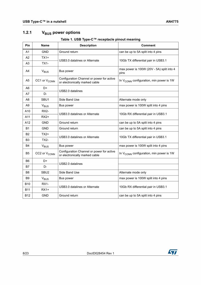
1.2.1 VBUS power options
Table 1. USB Type-C™ receptacle pinout meaning
Pin Name Description Comment
A1 GND Ground return can be up to 5A split into 4 pins
A2 TX1+USB3.0 datalines or Alternate 10Gb TX differential pair in USB3.1
A3 TX1-
A4 VBUS Bus powermax power is 100W (20V - 5A) split into 4 pins
A5 CC1 or VCONNConfiguration Channel or power for active or electronically marked cable
In VCONN configuration, min power is 1W
A6 D+USB2.0 datalines
A7 D-
A8 SBU1 Side Band Use Alternate mode only
A9 VBUS Bus power max power is 100W split into 4 pins
A10 RX2-USB3.0 datalines or Alternate 10Gb RX differential pair in USB3.1
A11 RX2+
A12 GND Ground return can be up to 5A split into 4 pins
B1 GND Ground return can be up to 5A split into 4 pins
B2 TX2+USB3.0 datalines or Alternate 10Gb TX differential pair in USB3.1
B3 TX2-
B4 VBUS Bus power max power is 100W split into 4 pins
B5 CC2 or VCONNConfiguration Channel or power for active or electronically marked cable
In VCONN configuration, min power is 1W
B6 D+USB2.0 datalines
B7 D-
B8 SBU2 Side Band Use Alternate mode only
B9 VBUS Bus power max power is 100W split into 4 pins
B10 RX1-USB3.0 datalines or Alternate 10Gb RX differential pair in USB3.1
B11 RX1+
B12 GND Ground return can be up to 5A split into 4 pins

DocID028454 Rev 1 9/23
AN4775 USB Type-C™ in a nutshell
22
VBUS provides a path to deliver power between a host and a device and between a charger and a host/device.
Power options available from a perspective of a device with a USB Type-C™ connector are listed below.
Remark: USB Type-C™ to Type-C cable assembly needs VBUS to be protected against 30V DC at cable rated current (3A or 5A).
Table 2. Power supply options
Mode of Operation Nominal Voltage Maximum current Note
USB2.0 5V 500mA Default current based on specificationUSB3.1 5V 900mA
USB BC1.2 5V up to 1.5A Legacy charging
USB Type-C™ [email protected]
5V 1.5ASupport high power devicesUSB Type-C™
Current@3A5V 3A
USB PD Up to 20V up to 5ADirectional control and power level management
CC Pins AN4775
10/23 DocID028454 Rev 1
2 CC Pins
There are two CC pins in receptacle but only one CC pin is connected in cable per plug facing port.
On both CC1 and CC2, DFP must have Rp pull up resistors, whereas UFP must have Rd pull down resistors.
Electronic cables need to provide impedance Ra to ground on VCONN
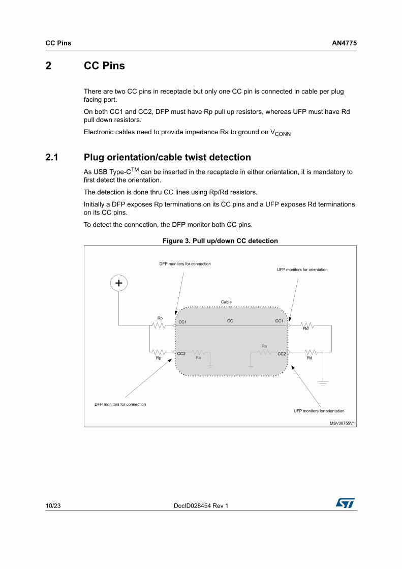
2.1 Plug orientation/cable twist detection
As USB Type-CTM can be inserted in the receptacle in either orientation, it is mandatory to first detect the orientation.
The detection is done thru CC lines using Rp/Rd resistors.
Initially a DFP exposes Rp terminations on its CC pins and a UFP exposes Rd terminations on its CC pins.
To detect the connection, the DFP monitor both CC pins.
Figure 3. Pull up/down CC detection

DocID028454 Rev 1 11/23
AN4775 CC Pins
22
2.2 Power Capability detection and usage
USB Type-C™ power has initially two main power options: 1.5A and 3A on top on default USB standard.
Current supply capability of the port to the device depends on Rp pull up resistor value on DFP.
5A capability can be negotiated using USB Power Delivery protocol.
Table 3 below shows the different possible values.
UFP must also implement on both CC1 and CC2 Rd pull down resistors for biasing the detection system and to be identified as power sinker.
UFP which is able to detect power capability needs to monitor CC lines voltage accurately in order to determine power capability of DFP.
Table 3. DFP CC termination (Rp) requirements
VBUS powerCurrent Source to
1.7V - 5.5VRp pull up to 4.75V - 5.5V
Rp pull up to 3.3V +/-5%
Default USB power 80A +/- 20% 56k+/- 20%(1)
1. For Rp when implemented in the USB Type-C™ plug on a USB Type-C™ to USB 3.1 Standard-A Cable Assembly, a USB Type-C™ to USB 2.0 Standard-A Cable Assembly, a USB Type-C™ to USB 2.0 Micro-B Receptacle Adapter Assembly or a USB Type-C™ captive cable connected to a USB host, a value of 56 kΩ ± 5% shall be used, in order to provide tolerance to IR drop on VBUS and GND in the cable assembly.
36k+/- 20%
1.5A @5V 180A +/- 8% 22k+/- 5% 12k+/- 5%
3.0A @5V 330A +/- 8% 10k+/- 5% 4.7k+/- 5%
Table 4. UFP CC Termination (Rd) Requirements
Rd implementation Nominal valueCan detect power
capability?max voltage on CC pin
+/- 20% voltage clamp 1.1V No 1.32V
+/- 20% resistor to GND 5.1k No 2.18V
+/- 10% resistor to GND 5.1k Yes 2.04V
Table 5. Voltage on Sink CC pins (Multiple Source Current Advertisements)
Detection Min voltage (V) Max voltage (V) Threshold (V)
vRa -0.25 0.15 0.2
vRd-Connect 0.25 2.04 -
vRd-USB 0.25 0.61 0.66
vRd-1.5 0.70 1.16 1.23
vRd-3.0 1.31 2.04 -

USB power delivery 2.0 AN4775
12/23 DocID028454 Rev 1
3 USB power delivery 2.0
In USB Power Delivery, pairs of directly attached ports negotiate voltage, current and/or direction of power and data flow over the USB cable, using the CC wire as the communication channel using BMC coding (Biphase Mark Coding).
The mechanisms used, operate independently of other USB methods used to negotiate power.
3.1 Power delivery signaling
All communications are done thru CC wire in half duplex with 300Kbps bit rate.
Communication consists in 32-bit 4b/5b words BMC encoded over CC wires.
3.1.1 Packet Structure
Packet format is:
Preamble: 64-bit sequence of alternating 0s and 1s to sync up with transmitter.
SOP* (start of packet) (can be SOP, SOP’ (start of packet sequence prime) or SOP” (start of packet sequence double prime) see Figure 4)
– SOP Packets shall be limited to PD capable DFP and UFP only
– SOP’ Packets are used for communication with Cable Plug attached to the DFP.
– SOP” Packets are used for communication with Cable Plug attached to the UFP.
A cable plug capable of SOP’ or SOP” communication shall only detect and communicate with packet starting with SOP’ or SOP”.
Message data including message header which identifies type of packet and amount of data.
CRC: Error checking.
EOP (end of packet): unique identifier.
Figure 4. SOP* signaling

DocID028454 Rev 1 13/23
AN4775 USB power delivery 2.0
22
3.1.2 K-codes
K-codes are special symbols provided by the 4b5b coding. They are used to signal hard reset and cable reset and delineate packet boundaries.
3.2 Negotiating Power
DFP is initially considered as a bus master.
The protocol layer allows the power configuration to be dynamically modified.
As such, power role, data role and VCONN swap are independently possible if both ports support dual power role functionality.
The default voltage on VBUS is always 5V and can be reconfigured up to 20V.
The default current capability is initially defined by Rp value and can be reconfigured up to 5A for an electronically marked USB PD Type-C cable.
The protocol uses start-of-packet (SOP) communications, each of which begins with an encoded symbol called K-code.
SOP communication contains a control or data message.
The control message has a 16-bit fixed size and is used to manage data flow.
The data message size varies depending on its contents. It provides information on data objects.

Alternate modes AN4775
14/23 DocID028454 Rev 1
4 Alternate modes
All the hosts and devices (except chargers) using a USB Type-C™ receptacle shall expose a USB interface.
If the host or device optionally supports Alternate Modes:
The host and device shall use USB Power Delivery Structured Vendor Defined Messages (Structured VDMs) to discover, configure and enter/exit modes to enable Alternate Modes.
It’s strongly encouraged that the device provides equivalent USB functionality where such exists for best user experience.
Where no equivalent USB functionality is implemented, the device shall provide a USB interface exposing a USB Billboard Device Class used to provide information needed to identify the device. A device is not required to provide a USB interface exposing a USB Billboard Device Class for non-user facing modes (e.g., diagnostic modes).
As Alternate Modes do not traverse the USB hub topology, they shall only be used between a directly connected host and device.
4.1 Alternate pins re-assignment
In the Figure 5 pins highlighted in yellow are the only pins that shall be reconfigured in a full-feature cable
Figure 5. Pins available for reconfiguration over the Full Featured Cable

DocID028454 Rev 1 15/23
AN4775 Alternate modes
22
Figure 6 shows pins available for reconfiguration for direct connect applications. There are three pins more than in previous figure because this configuration is not limited by the cable wiring.
Figure 6. Pins available for reconfiguration for direct connect applications
4.2 Billboard
The USB Billboard Device Class definition describes the methods used to communicate the Alternate Modes supported by a Device Container to a host system.
This includes string descriptors that can be used to provide support details in a human-readable format.
For more details, refer to USB Device Class Definition for Billboard Devices rev1.0a April 15, 2015
Converting STM32xx USB2.0 device only to USB Type-C™ platform AN4775
16/23 DocID028454 Rev 1
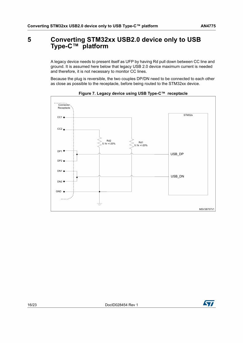
5 Converting STM32xx USB2.0 device only to USB Type-C™ platform
A legacy device needs to present itself as UFP by having Rd pull down between CC line and ground. It is assumed here below that legacy USB 2.0 device maximum current is needed and therefore, it is not necessary to monitor CC lines.
Because the plug is reversible, the two couples DP/DN need to be connected to each other as close as possible to the receptacle, before being routed to the STM32xx device.
Figure 7. Legacy device using USB Type-C™ receptacle
DocID028454 Rev 1 17/23
AN4775 Converting STM32xx USB2.0 host to USB Type-C™ platform
22
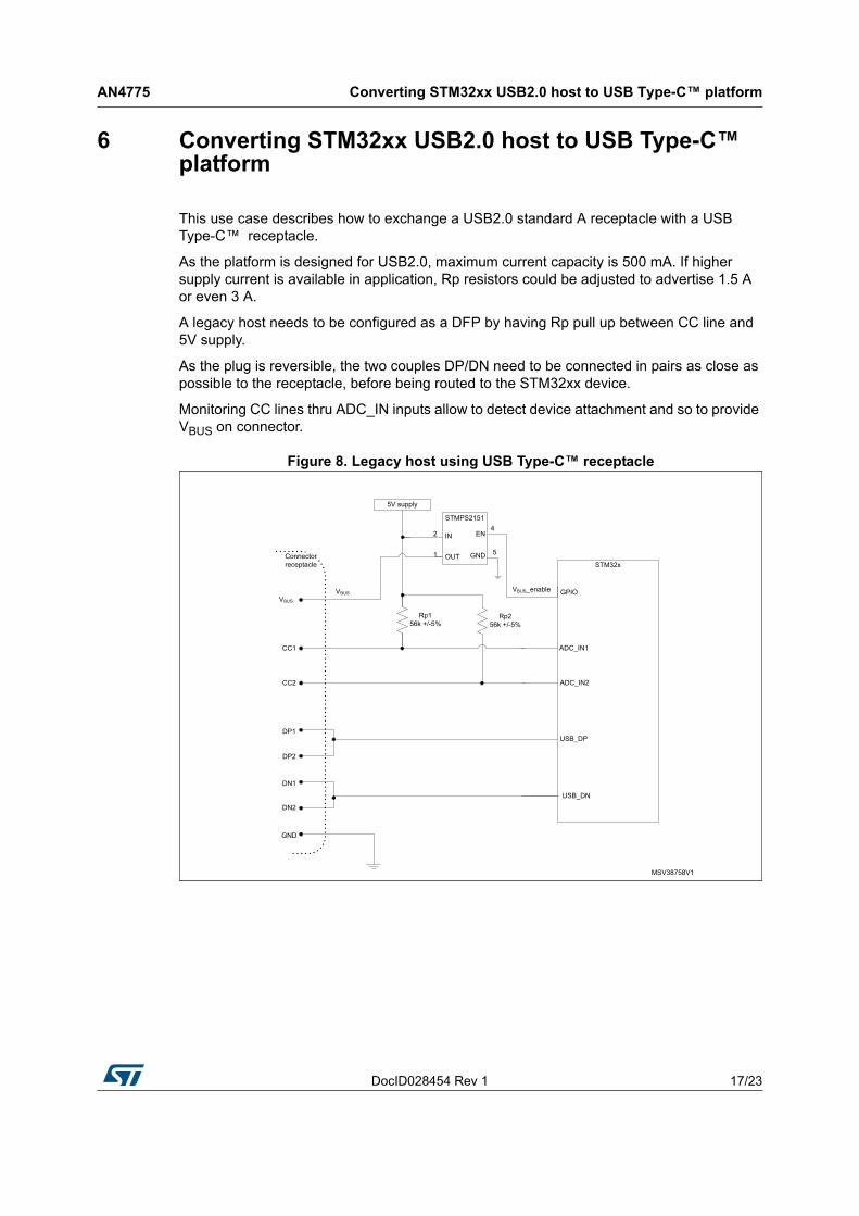
6 Converting STM32xx USB2.0 host to USB Type-C™ platform
This use case describes how to exchange a USB2.0 standard A receptacle with a USB Type-C™ receptacle.
As the platform is designed for USB2.0, maximum current capacity is 500 mA. If higher supply current is available in application, Rp resistors could be adjusted to advertise 1.5 A or even 3 A.
A legacy host needs to be configured as a DFP by having Rp pull up between CC line and 5V supply.
As the plug is reversible, the two couples DP/DN need to be connected in pairs as close as possible to the receptacle, before being routed to the STM32xx device.
Monitoring CC lines thru ADC_IN inputs allow to detect device attachment and so to provide VBUS on connector.
Figure 8. Legacy host using USB Type-C™ receptacle

Converting legacy STM32xx USB2.0 OTG to USB Type-C™ platform AN4775
18/23 DocID028454 Rev 1
7 Converting legacy STM32xx USB2.0 OTG to USB Type-C™ platform
This use case explains how to exchange USB2.0 micro-AB receptacle to USB Type-C™ receptacle.
As in this use case, the platform is designed for USB2.0, maximum current capacity is 500 mA. If higher supply current is available in application, Rp resistors could be adjusted to advertise 1.5 A or even 3 A.
A legacy OTG platform starts to work as host or device depending on USB_ID pin impedance to ground provided by cable.
USB Type-C™ is fully reversible so cable does not provide any information in role. Role needs to be detected by sensing CC lines.
Figure 9. Legacy OTG using USB Type-C™ receptacle
DocID028454 Rev 1 19/23
AN4775 Converting legacy STM32xx USB2.0 OTG to USB Type-C™ platform
22
Proposed sequence is:
1. GPIO connected to OTG_FS_DFP_UFP should be high and GPIO2 connected to Switch_enable should be low to identify platform as UFP.
2. If VBUS is detected: platform starts with USB2.0 controller acting as device.
3. If no VBUS is detected after 200 ms minimum, OTG_FS_DFP_UFP is pulled down to be identified as DFP thru Rp resistors and to check whether UFP is connected by comparing ADC_IN1 and ADC_IN2 voltages versus expected threshold on CC lines. Power switch X1 is kept disabled.
4. If UFP connection is detected, Switch_enable is pulled up to provide VBUS on connector and platform starts with USB2.0 controller acting as host.
Because of plug reversibility, the two couples DP/DN need to be connected by pair as close as possible to receptacle, before to be routed to STM32xx device.

Conclusion AN4775
20/23 DocID028454 Rev 1
8 Conclusion
This application notes gives basic knowledge of USB Type-C™ and USB Power Delivery standard.
Some simple schematics are given to help to make the jump from USB2.0 legacy connector to USB Type-C™ connector with very few passive components.

DocID028454 Rev 1 21/23
AN4775 References
22
9 References
USB2.0 Universal Serial Bus Revision 2.0 Specification
USB3.1 Universal Serial Bus Revision 3.1 Specification
USB PD USB Power Delivery Specification Revision 2.0, August 11, 2014
USB BCBattery Charging Specification Revision1.2 (including errata and ECNs through March 15, 2015), March 15, 2012
USB BB USB Device Class Definition for Billboard Devices rev1.0a April 15, 2015

Revision history AN4775
22/23 DocID028454 Rev 1
10 Revision history
Table 6. Document revision history
Date Revision Changes
04-Mar-2016 1 Initial release.
DocID028454 Rev 1 23/23
AN4775
23
IMPORTANT NOTICE – PLEASE READ CAREFULLY
STMicroelectronics NV and its subsidiaries (“ST”) reserve the right to make changes, corrections, enhancements, modifications, and improvements to ST products and/or to this document at any time without notice. Purchasers should obtain the latest relevant information on ST products before placing orders. ST products are sold pursuant to ST’s terms and conditions of sale in place at the time of order acknowledgement.
Purchasers are solely responsible for the choice, selection, and use of ST products and ST assumes no liability for application assistance or the design of Purchasers’ products.
No license, express or implied, to any intellectual property right is granted by ST herein.
Resale of ST products with provisions different from the information set forth herein shall void any warranty granted by ST for such product.
ST and the ST logo are trademarks of ST. All other product or service names are the property of their respective owners.
Information in this document supersedes and replaces information previously supplied in any prior versions of this document.
© 2016 STMicroelectronics – All rights reserved
Related Documents