' Freescale Semiconductor, Inc., 2006. All rights reserved. AN1950 Rev 4, 11/2006 Freescale Semiconductor Application Note Water Level Monitoring by: Michelle Clifford, Applications Engineer Sensor Products, Tempe, AZ INTRODUCTION Many washing machines currently in production use a mechanical sensor for water level detection. Mechanical sensors work with discrete trip points enabling water level detection only at those points. The purpose for this reference design is to allow the user to evaluate a pressure sensor for not only water level sensing to replace a mechanical switch, but also for water flow measurement, leak detection, and other solutions for smart appliances. This system continuously monitors water level and water flow using the temperature compensated MPXM2010GS pressure sensor in the low cost MPAK package, a dual op-amp, and the MC68HC908QT4, eight-pin microcontroller. SYSTEM DESIGN Pressure Sensor The pressure sensor family has three levels of integration Uncompensated, Compensated and Integrated. For this design, the MPXM2010GS compensated pressure sensor was selected because it has both temperature compensation and calibration circuitry on the silicon, allowing a simpler, yet more robust, system circuit design. An integrated pressure sensor, such as the MPXV5004G, is also a good choice for the design eliminating the need for the amplification circuitry. Figure 1. Water Level Reference Design Featuring a Pressure Sensor The height of most washing machine tubs is 40 cm, therefore the water height range that this system will be measuring is between 040 cm. This corresponds to a pressure range of 04 kPa. Therefore, the MPXM2010GS was selected for this system. The sensor sensitivity is 2.5 mV/kPa, with a full-scale span of 25 mV at the supply voltage of 10 V DC . The full-scale output of the sensor changes linearly with supply voltage, so a supply voltage of 5 V will return a full-scale span of 12.5 mV. (V S actual / V S spec ) * V OUT full-scale spec = V OUT full-scale (5.0 V/ 10 V) x 25 mV = 12.5 mV Since this application will only be utilizing 40 percent of the pressure range, 04kPa, our maximum output voltage will be 40 percent of the full-scale span. V OUT FS * (Percent FS Range ) = V OUT max 12.5 mV * 40% = 5.0 mV The package of the pressure sensor is a ported MPAK package. This allows a tube to be connected to the sensor and the tube is connected to the bottom of the tub. This isolates the sensor from direct contact with the water. The small size and low cost are additional features making this package a perfect fit for this application. Figure 2. A Ported Pressure Sensor

Welcome message from author
This document is posted to help you gain knowledge. Please leave a comment to let me know what you think about it! Share it to your friends and learn new things together.
Transcript

AN1950Rev 4, 11/2006
Freescale SemiconductorApplication Note
Water Level Monitoringby: Michelle Clifford, Applications Engineer
Sensor Products, Tempe, AZ
INTRODUCTIONMany washing machines currently in production use a
mechanical sensor for water level detection. Mechanical sensors work with discrete trip points enabling water level detection only at those points. The purpose for this reference design is to allow the user to evaluate a pressure sensor for not only water level sensing to replace a mechanical switch, but also for water flow measurement, leak detection, and other solutions for smart appliances. This system continuously monitors water level and water flow using the temperature compensated MPXM2010GS pressure sensor in the low cost MPAK package, a dual op-amp, and the MC68HC908QT4, eight-pin microcontroller.
SYSTEM DESIGN
Pressure SensorThe pressure sensor family has three levels of integration
Uncompensated, Compensated and Integrated. For this design, the MPXM2010GS compensated pressure sensor was selected because it has both temperature compensation and calibration circuitry on the silicon, allowing a simpler, yet more robust, system circuit design. An integrated pressure sensor, such as the MPXV5004G, is also a good choice for the design eliminating the need for the amplification circuitry.
Figure 1. Water Level Reference Design Featuring a Pressure Sensor
The height of most washing machine tubs is 40 cm, therefore the water height range that this system will be
measuring is between 040 cm. This corresponds to a pressure range of 04 kPa. Therefore, the MPXM2010GS was selected for this system. The sensor sensitivity is 2.5 mV/kPa, with a full-scale span of 25 mV at the supply voltage of 10 VDC. The full-scale output of the sensor changes linearly with supply voltage, so a supply voltage of 5 V will return a full-scale span of 12.5 mV.
(VS actual / VS spec) * VOUT full-scale spec = VOUT full-scale
(5.0 V/ 10 V) x 25 mV = 12.5 mV
Since this application will only be utilizing 40 percent of the pressure range, 04kPa, our maximum output voltage will be 40 percent of the full-scale span.
VOUT FS * (Percent FS Range) = VOUT max
12.5 mV * 40% = 5.0 mV
The package of the pressure sensor is a ported MPAK package. This allows a tube to be connected to the sensor and the tube is connected to the bottom of the tub. This isolates the sensor from direct contact with the water. The small size and low cost are additional features making this package a perfect fit for this application.
Figure 2. A Ported Pressure Sensor
© Freescale Semiconductor, Inc., 2006. All rights reserved.
Amplifier Induced ErrorsThe sensor output needs to be amplified before being
inputted directly to the microcontroller through an eight-bit A/D input pin. To determine the amplification requirements, the pressure sensor output characteristics and the 0-5 V input range for the A/D converter had to be considered.
The amplification circuit uses three op-amps to add an offset and convert the differential output of the MPXM2010GS sensor to a ground-referenced, single-ended voltage in the range of 05.0 V.
The pressure sensor has a possible offset of ±1 mV at the minimum rated pressure. To avoid a nonlinear response when a pressure sensor chosen for the system has a negative offset (VOFF), we added a 5.0 mV offset to the positive sensor output signal. This offset will remain the same regardless of the sensor output. Any additional offset the sensor or op-amp introduces is compensated for by software routines invoked when the initial system calibration is done.
To determine the gain required for the system, the maximum output voltage from the sensor for this application had to be determined. The maximum output voltage from the sensor is approximately 12.5 mV with a 5.0 V supply since the full-scale output of the sensor changes linearly with supply voltage. This system will have a maximum pressure of 4 kPa at 40 cm of water. At a 5.0 V supply, we will have a maximum sensor output of 5 mV at 4 kPa of pressure. To amplify the maximum sensor output to 5.0 V, the following gain is needed:
Gain = (Max Output needed) / (Max Sensor Output and Initial Offset) = 5.0 V / (0.005 V + 0.005) = 500
The gain for the system was set for 500 to avoid railing from possible offsets from the pressure sensor or the op-amp.
The Voltage Outputs from the sensor are each connected to a non-inverting input of an op-amp. Each op-amp circuit has the same resistor ratio. The amplified voltage signal from the negative sensor lead is VA. The resulting voltage is calculated as follows:
VA = (1+R8/R6) * V4
= (1+10/1000) * V4
= (1.001) * V4
The amplified voltage signal from the positive sensor lead is VB. This amplification adds a small gain to ensure that the positive lead, V2, is always greater than the voltage output from the negative sensor lead, V4. This ensures the linearity of the differential voltage signal.
VB = (1+R7/R5) * V2 (R7/R5) * VCC
= (1+10/1000) * V2 + (10/1000)*(5.0 V)
= (1.001) * V2 + 0.005 V
The difference between the positive sensor voltage, VB, and the negative sensor voltage, VA is calculated and amplified with a resulting gain of 500.
VC = (R12/R11) * (VB VA)
= (500 K/1K) * (VB VA)
= 500 * (VB VA)
The output voltage, VC, is connected to a voltage follower. Therefore, the resulting voltage, VC, is passed to an A/D pin of the microcontroller.
The range of the A/D converter is 0 to 255 counts. However, the A/D Values that the system can achieve are dependent on the maximum and minimum system output values:
Count = (VOUT VRL) / ( VRH VRL) x 255
where VXdcr = Transducer Output Voltage
VRH = Maximum A/D voltage
VLH = Minimum A/D voltage
Count (0 mm H20) = (2.5 0) / (5.0 0) * 255 = 127
Count (40 mm H20) = (5.0 0) / (5.0 0) * 255 = 255
Total # counts = 255 127 = 127 counts.
The resolution of the system is determined by the mm of water represented by each A/D count. As calculated above, the system has a span of 226 counts to represent water level up to and including 40 cm. Therefore, the resolution is:
Resolution = mm of water / Total # counts
= 400mm/127 counts = 3.1 mm per A/D count
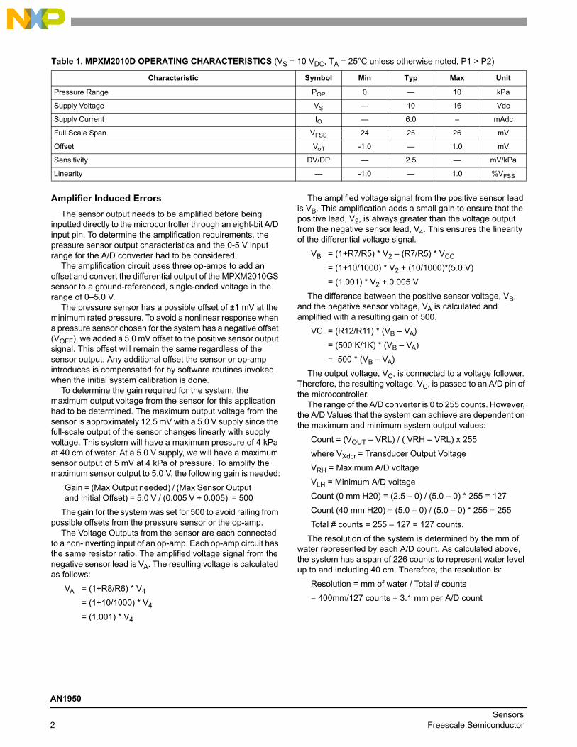
Table 1. MPXM2010D OPERATING CHARACTERISTICS (VS = 10 VDC, TA = 25°C unless otherwise noted, P1 > P2)
Characteristic Symbol Min Typ Max Unit
Pressure Range POP 0 10 kPa
Supply Voltage VS 10 16 Vdc
Supply Current IO 6.0 mAdc
Full Scale Span VFSS 24 25 26 mV
Offset Voff -1.0 1.0 mV
Sensitivity DV/DP 2.5 mV/kPa
Linearity -1.0 1.0 %VFSS
AN1950
Sensors2 Freescale Semiconductor

Figure 3. Amplification Scheme
MicroprocessorTo provide the signal processing for pressure values, a
microprocessor is needed. The MCU chosen for this application is the MC68HC908QT4. This MCU is perfect for appliance applications due to its low cost, small eight-pin package, and other on-chip resources. The MC68HC908QT4 provides: a four-channel, eight-bit A/D, a 16-bit timer, a trimmable internal timer, and in-system FLASH programming.
The central processing unit is based on the high performance M68HC08 CPU core and it can address 64 Kbytes of memory space. The MC68HC908QT4 provides 4096 bytes of user FLASH and 128 bytes of random access memory (RAM) for ease of software development and maintenance. There are five bi-directional input/output lines and one input line shared with other pin features.
The MCU is available in eight-pin as well as 16-pin packages in both PDIP and SOIC. For this application, the eight-pin PDIP was selected. The eight-pin PDIP was chosen for a small package, eventually to be designed into applications as the eight-pin SOIC. The PDIP enables the customer to reprogram the software on a programming board and retest.
DisplayDepending on the quality of the display required, water
level and water flow can be shown with two LEDs. If a higher quality, digital output is needed, an optional LCD interface is provided on the reference board. Using a shift register to hold display data, the LCD is driven with only three lines outputted from the microcontroller: an enable line, a data line, and a clock signal. The two LEDs are multiplexed with the data line and clock signal
Figure 4. Multiplexed LCD CircuitMultiplexing of the microcontroller output pins allows
communication of the LCD to be accomplished with three pins instead of eight or 11 pins of I/O lines usually needed. With an eight-bit shift register, we are able to manually clock in eight bits of data. The enable line (EN) is manually accepted when eight bytes have been shifted in, telling the LCD the data on the data bus is available to execute.
The LEDs are used to show pressure output data by displaying binary values corresponding to a pressure range. Leak detection, or water-flow speed, is displayed by blinking a green LED at a speed relating to the speed of water flow. The red LED displays the direction of water flow. Turning the red LED off signifies water flowing into the tub. Turning the red LED on signifies water flowing out of the tub, or alternatively, there is a leak.
Digital values for water height, rate of water flow, and calibration values are displayed if an LCD is connected to the board
R510K
R710Ω
R810ΩR6
10K
R111K
R91K R10
500K
R12500K
V2sensor
V4sensor
VOUT
VCC
C50.1µF
6
57
2
31
9
10813
1214
11
4
VCC
VA
VC
VB
+
-
+
-
+
-
+
-
HC908QT4 HC164
LCD
ENRSRW
DB0DB1DB2DB3DB4DB5DB6DB7
ABCLK
PTA4PTA3
PTA5
R3R21K1K
AN1950
SensorsFreescale Semiconductor 3

OTHERThis system is designed to run on a 9.0 V battery. It
contains a 5.0 V regulator to provide 5.0 V to the pressure
sensor, microcontroller, and LCD. The battery is mounted on the back of the board using a space saving spring battery clip.
Smart Washer SoftwareThis application note describes the first software version
available. However, updated software versions may be available with further functionality and menu selections.
Software User InstructionsWhen the system is turned on or reset, the microcontroller
will flash the selected LED and display the program title on the LCD for five seconds, or until the select (SEL) button is pushed. Then the menu screen is displayed. Using the select (SEL) pushbutton, it is easy to scroll through the menu options for a software program. To run the water level program, use the select button to highlight the Water Level option, then press the enter (ENT) pushbutton. The Water Level program will display current water level, the rate of flow, a message if the container is Filling, Emptying, Full, or Empty, and a scrolling graphical history displaying data points representing the past forty level readings.
The Water Level is displayed by retrieving the digital voltage from the internal A/D Converter. This voltage is converted to pressure in millimeters of water and then displayed on the LCD.
Calibration and Calibration SoftwareTo calibrate the system, a two-point calibration is
performed. The sensor will take a calibration point at 0 mm and at 40 mm of water. Depressing both the SEL and ENT
buttons on system power-up enters the calibration mode. At this point, the calibration menu is displayed with the previously sampled offset voltage. To recalibrate the system, expose the sensor to atmospheric pressure and press the SEL button (PB1). At this point, the zero offset voltage will be sampled and saved to a location in the microcontroller memory. To obtain the second calibration point, place the end of the plastic tube from the pressure sensor to the bottom of a container holding 40 mm of water. Then press the ENT button (PB2). The voltage output will be sampled, averaged and saved to a location in memory. To exit the calibration mode, press the SEL (PB1) button.
Figure 5. Water Level System Set-Up for Demonstration
Table 2. Parts List
Ref. Qty Description Value Vendor Part No.U2 1 Pressure Sensor 1 Freescale MPXM2010GS
C1 1 Vcc Cap 0.1µf Generic C2 1 Op-Amp Cap 0.1µf Generic C3 1 Shift Register Cap 0.1µf Generic D1 1 Red LED Generic D2 1 Green LED Generic
S2, S3 2 Pushbuttons Generic U1 1 Quad Op-Amp ADI AD8544
U3 1 Voltage Regulator 5.0 V Fairchild LM78L05ACH
U4 1 Microcontroller 8-pin Freescale MC68HC908QT4
R1 1 ¼ W Resistor 22 K Generic R2 1 ¼ W Resistor 2.4 K Generic
R3, R6 2 ¼ W Resistor 1.2 M Generic R4, R5 2 ¼ W Resistor 1.5 K Generic R7, R8 2 ¼ W Resistor 10 K Generic
R9, R10 2 ¼ W Resistor 1.0 K Generic U6 1 LCD (Optional) 16 x 2 Seiko L168200J000
U5 1 Shift Registor Texas Instruments 74HC164
AN1950
Sensors4 Freescale Semiconductor

Converting Pressure to Water LevelHydrostatic pressure being measured is the pressure at the
bottom of a column of fluid caused by the weight of the fluid and the pressure of the air above the fluid. Therefore, the hydrostatic pressure depends on the air pressure, the fluid density and the height of the column of fluid.
P= Pa + ρ g ∆h
where P = pressure
Pa = pressure
ρ = mass density of fluid
g = 9.8066 m/s^2
h = height of fluid column
To calculate the water height, we can use the measured pressure with the following equation, assuming the atmospheric pressure is already compensated for by the selection of the pressure sensor being gauge:
∆h = P \ ρ g
Software Function Descriptions
Main FunctionThe main function calls an initialization function Allinit calls
a warm-up function, Warmup, to allow extra time for the LCD to initialize, then checks if buttons PB1 and PB2 are depressed. If they are depressed concurrently, it calls a calibration function Calib. If they are not both pressed, it enters the main function loop. The main loop displays the menu, moves the cursor when the PB1 is pressed and enters the function corresponding to the highlighted menu option when PB2 is depressed.
Calibration FunctionThe calibration function is used to obtain two calibration
points. The first calibration point is taken when the head tube is not placed in water to obtain the pressure for 0 mm of water. The second calibration point is obtained when the head tube is placed at the bottom of a container with a height of 160 mm. When the calibration function starts, a message appears displaying the A/D values for the corresponding calibration points currently stored in the flash. To program new calibration points, press PB1 to take 256 A/D readings at 0 mm of water. The average is calculated and stored in a page of flash. Then the user has the option to press PB1 to exit the calibration function or obtain the second calibration point. To obtain the second calibration point, the head tube should be placed in 160 mm of water, before depressing PB2 to take 256 A/D readings. The average is taken and stored in a page of flash. Once the two readings are taken, averaged, and stored in the flash, a message displays the two A/D values stored.
Level FunctionThe Level function initializes the graphics characters. Once
this is complete, it continues looping to obtain an average A/D reading, displaying the Water Level, the Water Flow, and a Graphical History until simultaneously depressing both PB1 and PB2 to return to the main function.
The function first clears the 40 pressure readings it updates for the Graphical History. The history then enters the loop first displaying eight special characters, each containing five data points of water level history. The function adcbyta is called to obtain the current averaged A/D value. The function LfNx is called to convert the A/D value to a water level. It is then compared to the calibration points, the maximum and minimum points, to determine if the container is full or empty. If true, then it displays the corresponding message. The current water level is compared to the previous read and displays the message filling if it has increased, emptying if it has decreased, and steady if it has not changed.
The water level calculation has to be converted to decimal in order to display it in the LCD. To convert the water level calculation to decimal, the value is continually divided with the remainder displayed to the screen for each decimal place. To display the Rate of Water Flow, the sign of the value is first determined. If the value is negative, the one's complement is taken, a negative sign is displayed, and then the value is continually divided to display each decimal place. If the number is positive, a plus sign.
Level FunctionThe Level function initializes the graphics characters. Once
this is complete, it continues looping to obtain an average A/D reading, displaying the Water Level, the Water Flow, and a Graphical History until simultaneously depressing both PB1 and PB2 to return to the main function.
The function first clears the 40 pressure readings it updates for the Graphical History. The history then enters the loop first displaying eight special characters, each containing five data points of water level history. The function adcbyta is called to obtain the current averaged A/D value. The function LfNx is called to convert the A/D value to a water level. It is then compared to the calibration points, the maximum and minimum points, to determine if the container is full or empty. If true, then it displays the corresponding message. The current water level is compared to the previous read and displays the message filling if it has increased, emptying if it has decreased, and steady if it has not changed.
The water level calculation has to be converted to decimal in order to display it in the LCD. To convert the water level calculation to decimal, the value is continually divided with the remainder displayed to the screen for each decimal place. To display the Rate of Water Flow, the sign of the value is first determined. If the value is negative, the one's complement is taken, a negative sign is displayed, and then the value is continually divided to display each decimal place. If the number is positive, a plus sign is displayed to maintain the display alignment and the value is continually divided to display each decimal place.
The most complicated part of this function is updating the graphics history display. The characters for the 16x2 LCD chosen for this reference design are 8x5 pixels by default. Therefore, each special character that is created will be able to display five water level readings. Since the height of the special character is eight pixels, each vertical pixel position will represent a water level in increments of 20 mm.
Resolution = (H1 H0) / D
AN1950
SensorsFreescale Semiconductor 5

where H1 and H2 are the maximum and minimum water levels respectively and D is the possible datapoints available per character.
Resolution = (160mm 0mm) / 8.0 = 20 mm / data point.
The graphical history is displayed using the eight special characters. To update the graphics, all the characters have to be updated. The characters are updated by first positioning a pixel for the most recent water level reading in the first column of the first character. Then the four right columns of the first character are shifted to the right. The pixel in the last column of that character is carried to the first column of the next character. This column shifting is continued until all 40 data points have been updated in the eight special characters.
LfNx FunctionThe LfNx function calculates the water level from the
current A/D pressure reading. The A/D Pressure value is stored in Register A before this function is called. Using the A/D value and the calibration values stored in the flash, the water level is calculated from the following function:
RBRA: = (NX N1) * 160 / (N2 N1),
where NX is the current A/D Value
N1 is the A/D Value at 0 mm H20
N2 is the A/D Value at 160 mm H20
To simplify the calculation, the multiplication is done first. Then the function NdivD is called to divide the values.
NdivD FunctionThe NdivD function performs a division by counting
successive subtractions of the denominator from the numerator to determine the quotient. The denominator is subtracted from the numerator until the result is zero. If there is an overflow, the remainder from the last subtraction is the remainder of the division.
wrflash and ersflsh FunctionsThe wrflash and ersflsh functions are used to write to and
erase values from the flash. For more information regarding flash functionality, refer to Section Four, Flash Memory from the MC68HC908QY4/D Databook.
ALLINIT FunctionThe Allinit function disables the COP for this version of
software, sets the data direction bits, and disables the data to the LCD and turns off the LCD enable line. It also sets up the microcontroller's internal clock to half the speed of the bus clock. See Section 15, Computer Operating Properly, of the MC68908QT4 datasheet for information on utilizing the COP module to help software recover from runaway code.
WARMUP FunctionThe Warmup function alternates the blinking of the two
LEDs ten times. This gives the LCD some time to warm up. Then the function warmup calls the LCD initialization function, lcdinit.
bintasc FunctionThe binasc function converts a binary value to its ascii
representation.
A/D FunctionsThe A/D functions are used to input the amplified voltage
from the pressure sensor from channel 0 of the A/D converter. The function adcbyti will set the A/D control register, wait for the A/D reading and load the data from the A/D data register into the accumulator. The function adcbyta is used to obtain an averaged A/D reading by calling adcbyti 256 times and returning the resulting average in the accumulator.
LCD FunctionsThe LCD hardware is set up for multiplexing three pins from
the microcontroller using an eight-bit shift register. Channels three, four, and five are used on port A for the LCD enable (E), the LCD reset (RS), and the shift register clock bit, respectively. The clock bit is used to manually clock data from channel four into the eight-bit shift register. This is the same line as the LCD RS bit because the MSB of the data is low for a command and high for data. The RS bit prepares the LCD for instructions or data with the same bit convention. When the eight bits of data are available on the output pins of the shift register, the LCD enable (E) is toggled to receive the data.
The LCD functions consist of an initialization function lcdinit which is used once when the system is started and five output functions. The functions lcdcmdo and lcdchro both send a byte of data. The function shiftA is called by both lcdcmdo and lcdchro to manually shift eight bits of data into the shift register. The function lcdnibo converts the data to binary before displaying. The lcdnibo displays a byte of data by calling lcdnibo for each nibble of data. The function lcdnibo enables strings to be easily added to the software for display. The function accepts a comma- delimited string of data consisting of 12 commands for clearing the screen and positioning the cursor. It then continues to output characters from the string until the @ symbol is found, signally the end of the string.
CONCLUSIONThe water level reference design uses a MPXM2010GS
pressure sensor in the low cost MPAK package, the low cost, eight-pin microcontroller, and a quad op-amp to amplify the sensor output voltage. This system uses very few components, reducing the overall system cost. This allows for a solution to compete with a mechanical switch for water level detection but also offer additional applications such as monitoring water flow for leak detection, and the other applications for smart washing machines.
AN1950
Sensors6 Freescale Semiconductor

SOFTWARE LISTING;NitroWater 2.0 24Jan03;--------------;;Water Level Reference Design;****************************; - uses 908QT4 (MC68HC908QT4) and MPAK (MPXM2010GS); CALIB: 2-point pressure calibration (0mm and 160mm); LEVEL: displays water level, flow, and graphics; UNITS: allows user to select between cm and inches;;__________________________________________________________ram equ $0080 ;memory pointersrom equ $EE00vectors equ $FFDE;__________________________________________________________porta equ $00 ;registersddra equ $04config2 equ $1Econfig1 equ $1Ftsc equ $20tmodh equ $23icgcr equ $36adscr equ $3Cadr equ $3Eadiclk equ $3Fflcr equ $FE08flbpr equ $FFBE;__________________________________________________________ org $FD00 ;flash variablesN1 db $96 ;1st calibration pt. = 0mm org $FD40N2 db $F6 ;2nd calibration pt. = 160mm org $FD80;__________________________________________________________ org vectors dw cold ;ADC dw cold ;Keyboard dw cold ;not used dw cold ;not used dw cold ;not used dw cold ;not used dw cold ;not used dw cold ;not used dw cold ;not used dw cold ;not used dw cold ;TIM Overflow dw cold ;TIM Channel 1 dw cold ;TIM Channel 0 dw cold ;not used dw cold ;IRQ dw cold ;SWI dw cold ;RESET ($FFFE);__________________________________________________________ org ramBB ds 1 ;variablesflshadr ds 2flshbyt ds 1memSP ds 2mem03 ds 2
AN1950
SensorsFreescale Semiconductor 7
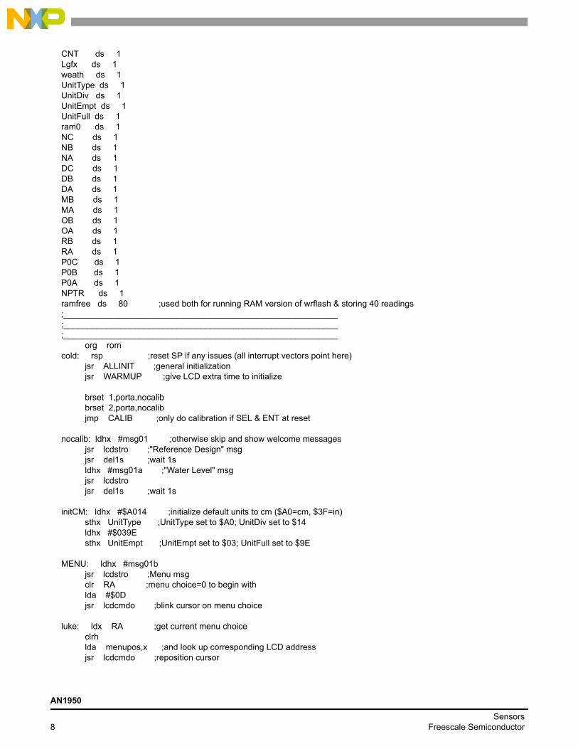
CNT ds 1Lgfx ds 1weath ds 1UnitType ds 1UnitDiv ds 1UnitEmpt ds 1UnitFull ds 1ram0 ds 1NC ds 1NB ds 1NA ds 1DC ds 1DB ds 1DA ds 1MB ds 1MA ds 1OB ds 1OA ds 1RB ds 1RA ds 1P0C ds 1P0B ds 1P0A ds 1NPTR ds 1ramfree ds 80 ;used both for running RAM version of wrflash & storing 40 readings;__________________________________________________________;__________________________________________________________;__________________________________________________________ org romcold: rsp ;reset SP if any issues (all interrupt vectors point here) jsr ALLINIT ;general initialization jsr WARMUP ;give LCD extra time to initialize
brset 1,porta,nocalib brset 2,porta,nocalib jmp CALIB ;only do calibration if SEL & ENT at reset
nocalib: ldhx #msg01 ;otherwise skip and show welcome messages jsr lcdstro ;"Reference Design" msg jsr del1s ;wait 1s ldhx #msg01a ;"Water Level" msg jsr lcdstro jsr del1s ;wait 1s
initCM: ldhx #$A014 ;initialize default units to cm ($A0=cm, $3F=in) sthx UnitType ;UnitType set to $A0; UnitDiv set to $14 ldhx #$039E sthx UnitEmpt ;UnitEmpt set to $03; UnitFull set to $9E
MENU: ldhx #msg01b jsr lcdstro ;Menu msg clr RA ;menu choice=0 to begin with lda #$0D jsr lcdcmdo ;blink cursor on menu choice
luke: ldx RA ;get current menu choice clrh lda menupos,x ;and look up corresponding LCD address jsr lcdcmdo ;reposition cursor
AN1950
Sensors8 Freescale Semiconductor

warm: brclr 1,porta,PB1 ;check for SEL brclr 2,porta,PB2 ;or for ENT bclr 4,porta ;otherwise bset 5,porta ;turn on "SEL" LED jsr del100ms ;delay bset 4,porta ;toggle LEDs bclr 5,porta ;"ENT" now on: means choice is SEL ***or*** ENT jsr del100ms ;delay and repeat until SEL or ENT bra warm
PB1: inc RA ;***SEL*** toggles menu choices lda RA cmp #$02 ;menu choices are $00 and $01 bne PB1ok clr RA ;back to $00 when all others have been offeredPB1ok: bclr 4,porta bclr 5,porta ;LEDs off jsr del100ms ;wait a little bit brclr 1,porta,PB1ok ;make sure they let go of SEL bra luke
PB2: bclr 4,porta ;***ENT*** confirms menu choice bclr 5,porta ;LEDs off lda RA ;get menu choice bne skip00 jmp LEVEL ;do ===LEVEL=== if choice=$01skip00: jmp UNITS ;do ===UNITS=== if choice=$00;__________________________________________________________;__________________________________________________________CALIB: lda #$01 jsr lcdcmdo clr ram0
ldhx #msg05 ;===CALIB=== 2-point calibration jsr lcdstro ;Calibration current values lda N1 ;0mm jsr lcdbyto lda #'/' jsr lcdchro lda N2 ;160mm jsr lcdbyto bset 4,porta bset 5,porta ;LEDs onlego1: brclr 1,porta,lego1lego2: brclr 2,porta,lego2 bclr 4,porta bclr 5,porta ;LEDs off when both SEL & ENT are released jsr del1s jsr del1s ;wait 2s ldhx #msg05a jsr lcdstro ;show instructionswaitPB1: brset 2,porta,no2 ;if ENT is not pressed, skip jmp nocalib ;if ENT is pressed then cancel calibrationno2: brclr 1,porta,do1st ;if SEL is pressed then do 1st point cal bra waitPB1 ;otherwise wait for SEL or ENTdo1st: ldhx #msg05b ;1st point cal: show values jsr lcdstro clr CNT ;CNT will count 256 A/D readings clr RB clr RA ;RB:RA will contain 16-bit add-up of those 256 values
AN1950
SensorsFreescale Semiconductor 9
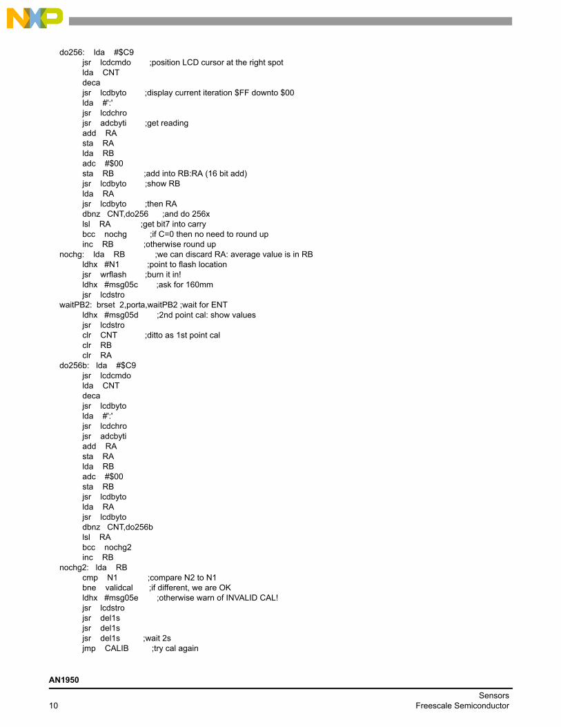
do256: lda #$C9 jsr lcdcmdo ;position LCD cursor at the right spot lda CNT deca jsr lcdbyto ;display current iteration $FF downto $00 lda #':' jsr lcdchro jsr adcbyti ;get reading add RA sta RA lda RB adc #$00 sta RB ;add into RB:RA (16 bit add) jsr lcdbyto ;show RB lda RA jsr lcdbyto ;then RA dbnz CNT,do256 ;and do 256x lsl RA ;get bit7 into carry bcc nochg ;if C=0 then no need to round up inc RB ;otherwise round upnochg: lda RB ;we can discard RA: average value is in RB ldhx #N1 ;point to flash location jsr wrflash ;burn it in! ldhx #msg05c ;ask for 160mm jsr lcdstrowaitPB2: brset 2,porta,waitPB2 ;wait for ENT ldhx #msg05d ;2nd point cal: show values jsr lcdstro clr CNT ;ditto as 1st point cal clr RB clr RAdo256b: lda #$C9 jsr lcdcmdo lda CNT deca jsr lcdbyto lda #':' jsr lcdchro jsr adcbyti add RA sta RA lda RB adc #$00 sta RB jsr lcdbyto lda RA jsr lcdbyto dbnz CNT,do256b lsl RA bcc nochg2 inc RBnochg2: lda RB cmp N1 ;compare N2 to N1 bne validcal ;if different, we are OK ldhx #msg05e ;otherwise warn of INVALID CAL! jsr lcdstro jsr del1s jsr del1s jsr del1s ;wait 2s jmp CALIB ;try cal again
AN1950
Sensors10 Freescale Semiconductor
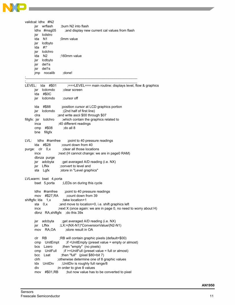
validcal: ldhx #N2 jsr wrflash ;burn N2 into flash ldhx #msg05 ;and display new current cal values from flash jsr lcdstro lda N1 ;0mm value jsr lcdbyto lda #'/' jsr lcdchro lda N2 ;160mm value jsr lcdbyto jsr del1s jsr del1s jmp nocalib ;done!;__________________________________________________________;__________________________________________________________LEVEL: lda #$01 ;===LEVEL=== main routine: displays level, flow & graphics jsr lcdcmdo ;clear screen lda #$0C jsr lcdcmdo ;cursor off
lda #$88 ;position cursor at LCD graphics portion jsr lcdcmdo ;(2nd half of first line) clra ;and write ascii $00 through $07fillgfx: jsr lcdchro ;which contain the graphics related to inca ;40 different readings cmp #$08 ;do all 8 bne fillgfx
LVL: ldhx #ramfree ;point to 40 pressure readings lda #$28 ;count down from 40purge: clr 0,x ;clear all those locations incx ;next (H cannot change: we are in page0 RAM) dbnza purge jsr adcbyta ;get averaged A/D reading (i.e. NX) jsr LfNx ;convert to level and sta Lgfx ;store in "Level graphics"
LVLwarm: bset 4,porta bset 5,porta ;LEDs on during this cycle
ldhx #ramfree ;point to 40 pressure readings mov #$27,RA ;count down from 39shiftgfx: lda 1,x ;take location+1 sta 0,x ;and move to location+0, i.e. shift graphics left incx ;next X (once again: we are in page 0, no need to worry about H) dbnz RA,shiftgfx ;do this 39x
jsr adcbyta ;get averaged A/D reading (i.e. NX) jsr LfNx ;LX:=(NX-N1)*ConversionValue/(N2-N1) mov RA,OA ;store result in OA
clr RB ;RB will contain graphic pixels (default=$00) cmp UnitEmpt ;if <UnitEmpty (preset value = empty or almost) bcs Lzero ;then "empty" (no pixels) cmp UnitFull ;if >=UnitFull (preset value = full or almost) bcc Lsat ;then "full" (pixel $80=bit 7) clrh ;otherwise determine one of 8 graphic values ldx UnitDiv ;UnitDiv is roughly full range/8 div ;in order to give 8 values mov #$01,RB ;but now value has to be converted to pixel
AN1950
SensorsFreescale Semiconductor 11

cmp #$01 ;if result is $01 beq Lzero ;then display it directlymakeRB lsl RB ;otherwise shift 1 pixel bit to the right place dbnza makeRB ;by counting down result of division bra LzeroLsat: mov #$80,RB ;if full then position highest pixelLzero: lda RB ldhx #ramfree+$27 ;last of the 40 sta 0,x ;put it at then end of the 40 bytes (new value), all others were shifted left
clr weath ;weath will contain dynamic change based also on value of RB lda RB beq donew ;if RB=$00 then weath=$00: "empty" cmp #$80 bne notfull ; mov #$01,weath ;if $80 then weath=$01: "full" bra donewnotfull mov #$02,weath ;prepare for "steady" if L(i)=L(i-1) lda OA ;get current level value L(i) cmp Lgfx ;compare to previous level value L(i-1) beq donew mov #$03,weath ;"filling" if L(i)>L(i-1) bcc donew mov #$04,weath ;"emptying" otherwise
donew: lda OA ;current level L(i) sub Lgfx ;minus previous level L(i-1) sta MA ;establishes rate: L(i)-L(i-1) mov RA,Lgfx ;update L(i-1);- - - - - - - - - - - - - - - - - - - - - - - - - - - - - - - - - -golevel: lda #$80 ;******** now let's display the level in decimal ******** jsr lcdcmdo ;start on 1st character of 1st line
lda OA ;get current level value clrh ldx #$64 ;and divide by 100 div bne over100 ;if result is >0 then handle "hundreds" lda #$20 ;otherwise display space (remove leading 0) jsr lcdchro bra lnextover100: jsr lcdnibo ;display "hundreds" digitlnext: pshh pula ;move remainder into A clrh ldx #$0A ;divide by 10 div jsr lcdnibo ;display "tens" digit lda #'.' jsr lcdchro ;display decimal point pshh pula jsr lcdnibo ;and first decimal lda UnitType ;check for cm ($A0) vs. in (#3F) cmp #$3F beq dsplIN
dsplCM: lda #'c' jsr lcdchro lda #'m'
AN1950
Sensors12 Freescale Semiconductor

jsr lcdchro ;display "cm" for centimeters bra goflow
dsplIN: lda #'i' jsr lcdchro lda #'n' jsr lcdchro ;display "in" for inches;- - - - - - - - - - - - - - - - - - - - - - - - - - - - - - - - - -goflow: lda #$C0 ;******** now let's display the flow in decimal ******** jsr lcdcmdo ;position cursor on 1st character 2nd line lda MA ;get flow lsla ;test sign of rate (in MA) bcc positiv ;if positive, then it's easy
lda MA ;otherwise 1's complement of MB coma inca sta MA cmp #$64 ;check to see if >100 bcs not2lo ;if not we are OK lda #'<' ;otherwise display that we exceeded min rate jsr lcdchro ;that LCD can display (<9.9) lda #$63 ;force value to 99 sta MA bra goconv
not2lo: lda #'-' jsr lcdchro ;display that minus sign bra goconv
positiv: lda MA cmp #$64 ;check to see if >100 bcs not2hi ;if not we are OK lda #'>' ;otherwise display that we exceeded max rate jsr lcdchro ;that LCD can display (>9.9) lda #$63 ;force value to 99 sta MA bra goconv
not2hi: lda #'+' jsr lcdchro ;display the plus sign (to keep alignment)
goconv: lda MA ;get flow clrh ldx #$0A ;and divide by 10 div jsr lcdnibo ;display "tens" digit lda #'.' jsr lcdchro ;display decimal point pshh pula jsr lcdnibo ;and first decimal lda UnitType ;check for cm ($A0) vs. in (#3F) cmp #$3F beq dsplINf
dsplCMf: lda #'c' jsr lcdchro lda #'m' bra reusef
AN1950
SensorsFreescale Semiconductor 13

dsplINf: lda #'i' jsr lcdchro lda #'n'reusef: jsr lcdchro lda #'/' jsr lcdchro lda #'s' jsr lcdchro;- - - - - - - - - - - - - - - - - - - - - - - - - - - - - - - - - -gfxupdt: lda #$40 ;======== Graphics Update: tough stuff =========== jsr lcdcmdo ;prepare to write 8 bytes into CGRAM starting at @ $40ldhx#ramfree;point to 40 pressure readings (this reuses wrflash RAM) mov #$08,DA ;DA will count those 8 CGRAM addressescg8: lda 0,x sta NC lda 1,x sta NB lda 2,x sta NA lda 3,x sta DC lda 4,xstaDB;readings 0-4 go into NC,NB,NA,DC,DB and will form 1 LCD specialcharacter mov #$08,RA ;RA will count the 8 bitsfill:clrRB;start with RB=0, this will eventually contain the data for CGRAM rol NC rolRB rol NB rolRB rol NA rolRB rol DC rolRB rol DBrolRB;rotate left those 5 values and use carry bits to form RB (tough part) lda RBjsrlcdchro;and put it into CGRAMdec RA ;do this 8 times to cover all 8 bits bne fill incx incx incx incx incx ;now point to next 5 values for next CGRAM address (5 values per character) dec DA ;do this for all 8 CGRAM characters bne cg8
ldaweath;get weather variable and decide which message to display cmp #$04 bne try3210 ldhx #msg02e ;if $04 bra showittry3210: cmp #$03 bne try210 ldhx #msg02d ;if $03 bra showittry210: cmp #$02
AN1950
Sensors14 Freescale Semiconductor
bne try10 ldhx #msg02c ;if $02 bra showittry10: cmp #$01 bne try0 ldhx #msg02b ;if $01 bra showittry0: ldhx #msg02a ;otherwise this oneshowit: jsr lcdstro jsr del1s ;1s between pressure/altitude readings brset 1,porta,contin ;exit only if SEL brset 2,porta,contin ;and ENT pressed together jmp MENUcontin: jmp LVLwarm;__________________________________________________________LfNx: sub N1 ;*** PX=f(NX,N2,N1) *** ldx UnitType ;$A0=160 for cm, $3F=63 for in mul sta NA stx NB clr NC ;NCNBNA:=(NX-N1)* (conversion value: 160 or 63)
lda N2 sub N1 sta DA clr DB clr DC jsr NdivD ;RBRA:=(NX-N1)*(conversion value)/(N2-N1)
lda RA cmp #$C8 ;check to see if result is negative bcs noovflw ;if <$C8 we are OKovflw: clr RA ;otherwise force level to 0!noovflw: lda RA rts;__________________________________________________________NdivD: clr RA ;RBRA:=NCNBNA/DCDBDA clr RB ;destroys NCNBNA and DCDBDAkeepatit: lda RA add #$01 sta RA lda RB adc #$00 sta RB ;increment RB:RA lda NA sub DA sta NA lda NB sbc DB sta NB lda NC sbc DC sta NC ;NC:NB:NA:=NC:NB:NA-DC:DB:DA bcc keepatit ;keep counting how many times until overflow lda RA sub #$01 sta RA lda RB sbc #$00 sta RB ;we counted once too many, so undo that
AN1950
SensorsFreescale Semiconductor 15
lsr DC ror DB ror DA ;divide DC:DB:DA by 2 lda NA add DA sta NA lda NB adc DB sta NB lda NC adc DC sta NC ;and add into NC:NB:NA lsla bcs nornd ;if carry=1 then remainder<1/2 of dividend lda RA add #$01 sta RA lda RB adc #$00 sta RB ;otherwise add 1 to resultnornd: rts;__________________________________________________________;__________________________________________________________UNITS: brclr 2,porta,UNITS ;let go of ENT first lda #$01 ;===UNITS=== Allows user to select units: inches or cm jsr lcdcmdo ;clear screen
ldhx #msg03 jsr lcdstro ;Unit Choice menu jsr del100ms clr RA ;menu choice=0 to begin with lda #$0D jsr lcdcmdo ;blink cursor on menu choice
uluke: ldx RA ;get current menu choice clrh lda menupos,x ;and look up corresponding LCD address jsr lcdcmdo ;reposition cursor
uwarm: brclr 1,porta,uPB1 ;check for SEL brclr 2,porta,uPB2 ;or for ENT bclr 4,porta ;otherwise bset 5,porta ;turn on "SEL" LED jsr del100ms ;delay bset 4,porta ;toggle LEDs bclr 5,porta ;"ENT" now on: means choice is SEL ***or*** ENT jsr del100ms ;delay and repeat until SEL or ENT bra uwarm
uPB1: inc RA ;***SEL*** toggles menu choices lda RA cmp #$02 ;menu choices are $00 and $01 bne uPB1ok clr RA ;back to $00 when all others have been offereduPB1ok: bclr 4,porta bclr 5,porta ;LEDs off jsr del100ms ;wait a little bit brclr 1,porta,uPB1ok ;make sure they let go of SEL bra uluke
AN1950
Sensors16 Freescale Semiconductor

uPB2: bclr 4,porta ;***ENT*** confirms menu choice bclr 5,porta ;LEDs off lda RA ;get menu choice bne SelIN
SelCM: ldhx #$A014 ;initialize default units to cm ($A0=cm, $3F=in) sthx UnitType ;UnitType set to $A0; UnitDiv set to $14 ldhx #$039E sthx UnitEmpt ;UnitEmpt set to $03; UnitFull set to $9E lda #$01 jsr lcdcmdo ;clear LCD ldhx #msg03a jsr lcdstro ;and show choice selection to be cm jsr del1s ;wait 1s jmp LEVEL ;let's do LEVEL now...
SelIN: ldhx #$3F08 ;initialize default units to in ($A0=cm, $3F=in) sthx UnitType ;UnitType set to $3F; UnitDiv set to $08 ldhx #$033D sthx UnitEmpt ;UnitEmpt set to $03; UnitFull set to $3D lda #$01 jsr lcdcmdo ;clear LCD ldhx #msg03b jsr lcdstro ;and show choice selection to be in jsr del1s ;wait 1s jmp LEVEL ;let's do LEVEL now...;__________________________________________________________;__________________________________________________________;__________________________________________________________
;********************************************************************;********************************************************************;******** GENERAL Routines ******************************************;********************************************************************;********************************************************************
;-------- INITIALIZATION Routines -----------------------------------; ALLINIT: initializes HC08, sets I/O, resets LCD and LEDs; -------ALLINIT: bset 0,config1 ;disable COP mov #$38,ddra ;PTA0=MPAK,PTA1=SEL,PTA2=ENT,PTA3=E,PTA4=RS,PTA5=clk mov #$30,adiclk ;ADC clock /2 bclr 3,porta ;E=0 bclr 4,porta ;grn=OFF; RS=0 bclr 5,porta ;red=OFF; CLK=0 rts;- - - - - - - - - - - - - - - - - - - - - - - - - - - - - - - - - -; WARMUP: waits half a second while it flashes LEDs, and allows LCD to get ready; ------WARMUP: bclr 4,porta bclr 5,porta ;LEDs off lda #$0A ;prepare to do this 10xtenx: jsr del25ms ;delay bclr 4,porta bset 5,porta ;alternate on/off jsr del25ms bset 4,porta bclr 5,porta ;and off/on dbnza tenx ;10 times so the LCD can get ready (slow startup) jsr lcdinit ;now initialize it
AN1950
SensorsFreescale Semiconductor 17
bclr 4,porta bclr 5,porta ;LEDs off rts;-------- WRITE TO EEPROM Routines ----------------------------------; wrflash: burns A into flash at location pointed by H:X; -------wrflash: sthx flshadr ;this is the address in the flash sta flshbyt ;and the byte we want to put there tsx sthx memSP ;store SP in memSP, so it can be temporarily used as a 2nd index register ldhx #ramfree+1 ;SP now points to RAM (remember to add 1 to the address!!!, HC08 quirk) txs ;SP changed (careful not to push or call subroutines) ldhx #ersflsh ;H:X points to beginning of flash programming codedoall: lda 0,x ;get 1st byte from flash sta 0,sp ;copy it into RAM aix #$0001 ;HX:=HX+1 ais #$0001 ;SP:=SP+1 cphx #lastbyt ;and continue until we reach the last byte bne doall ldhx memSP ;once done, restore the SP txs jsr ramfree ;and run the subroutine from RAM, you cannot write the flash while rts ;running a code in it, so the RAM has to take over for that piece;- - - - - - - - - - - - - - - - - - - - - - - - - - - - - - - - - -;*************** THE FOLLOWING CODE WILL BE COPIED INTO AND WILL RUN FROM RAM ******ersflsh: lda #$02 ;textbook way to erase flash sta flcr lda flbpr clra ldhx flshadr sta 0,x bsr delayf lda #$0A sta flcr bsr delayf lda #$08 sta flcr bsr delayf clra sta flcr bsr delayfpgmflsh: lda #$01 ;textbook way to program flash sta flcr lda flbpr clra ldhx flshadr sta 0,x bsr delayf lda #$09 sta flcr bsr delayf lda flshbyt ldhx flshadr sta 0,x bsr delayf lda #$08 sta flcr bsr delayf clra sta flcr
AN1950
Sensors18 Freescale Semiconductor
bsr delayf rtsdelayf: ldhx #$0005 ;wait 5x20us mov #$36,tsc ;stop TIM & / 64 sthx tmodh ;count H:X x 20us bclr 5,tsc ;start clockdelayfls: brclr 7,tsc,delayfls rts ;this RTS will move from RAM back into EEPROMlastbyt: nop;*************** END OF CODE THAT WILL BE COPIED INTO AND WILL RUN FROM RAM ******;-------- DELAY Routines --------------------------------------------; del1s: generates a 1s delay; -----del1s: pshh pshx ldhx #$C350 ;1 second delay=$C350=50000 x 20us bra delmain;- - - - - - - - - - - - - - - - - - - - - - - - - - - - - - - - - -; del100ms: generates a 100ms delay; --------del100ms: pshh pshx ldhx #$1388 bra delmain;- - - - - - - - - - - - - - - - - - - - - - - - - - - - - - - - - -; del50ms: generates a 50ms delay; -------del50ms: pshh pshx ldhx #$09C4 bra delmain;- - - - - - - - - - - - - - - - - - - - - - - - - - - - - - - - - -; del25ms: generates a 25ms delay; -------del25ms: pshh pshx ldhx #$04E2 bra delmain;- - - - - - - - - - - - - - - - - - - - - - - - - - - - - - - - - -; del5ms: generates a 5ms delay; ------del5ms: pshh pshx ldhx #$00FA bra delmain;- - - - - - - - - - - - - - - - - - - - - - - - - - - - - - - - - -; del1ms: generates a 1ms delay; ------del1ms: pshh pshx ldhx #$0032 bra delmain;- - - - - - - - - - - - - - - - - - - - - - - - - - - - - - - - - -; del100us: generates a 100us delay; -----del100us: pshh pshx ldhx #$0005 bra delmain;- - - - - - - - - - - - - - - - - - - - - - - - - - - - - - - - - -
AN1950
SensorsFreescale Semiconductor 19

; delmain: main delay routine; generates delay equal to H:X x 20us; -------delmain: mov #$36,tsc ;stop TIM & / 64 sthx tmodh ;count H:X x 20us bclr 5,tsc ;start clockdelwait: brclr 7,tsc,delwait ;wait for end of countdown pulx pulh rts ;this RTS serves for all delay routines!;-------- A/D Routines ----------------------------------------------; adcbyti: gets single A/D reading from PTA0 and returns it in A; -------adcbyti: mov #$00,adscr ;ADC set to PTA0 brclr 7,adscr,* ;wait for ADC reading lda adr ;result in adr rts;- - - - - - - - - - - - - - - - - - - - - - - - - - - - - - - - - -; adcbyta: gets averaged A/D reading from PTA0 and returns it in A; -------adcbyta: clr CNT ;average 256 readings clr RB ;will be addint them up clr RA ;in RB:RAdo256a: bsr adcbyti add RA sta RA lda RB adc #$00 sta RB ;16-bit add into RB:RA dbnz CNT,do256a ;do all 256 lsl RA ;if RA<$80 bcc nochga ;then RB result is correctly rounded inc RB ;otherwise round off to next valuenochga: lda RB rts;-------- LCD Routines ----------------------------------------------; lcdinit: initializes LCD; -------lcdinit: lda #$3C ;set 8-bit interface, 1/16 duty, 5x10 dots bsr lcdcmdo lda #$0C ;display on, cursor off, blink off bsr lcdcmdo lda #$06 ;increment cursor position, no display shift bsr lcdcmdo lda #$01 ;clear display bsr lcdcmdo rts;- - - - - - - - - - - - - - - - - - - - - - - - - - - - - - - - - -; lcdcmdo: sends a command to LCD; -------lcdcmdo: bsr shiftA bclr 4,porta ;RS=0 for command bset 3,porta bclr 3,porta ;toggle E bsr del5ms ;some commands require 2ms for LCD to execute rts ;so let's play it safe;- - - - - - - - - - - - - - - - - - - - - - - - - - - - - - - - - -; lcdchro: sends a character (data) to LCD; -------lcdchro: bsr shiftA bset 4,porta ;RS=1 for data
AN1950
Sensors20 Freescale Semiconductor
bset 3,porta bclr 3,porta ;toggle E bsr del100us ;data only requires 40us for LCD to execute rts;- - - - - - - - - - - - - - - - - - - - - - - - - - - - - - - - - -; shiftA: shifts A into shift register and provides 8-bits to LCD; ------shiftA: psha mov #$08,BB ;will be shifting 8 bitsall8: lsla ;get bit bcc shift0 ;if bit=0 then shift a 0shift1: bset 4,porta ;otherwise shift a 1 bra shiftshift0: bclr 4,porta ;bit 4 is data to shift registershift: bclr 5,porta ;bit 5 is shift register clock bset 5,porta bclr 5,porta ;toggle CLK dbnz BB,all8 ;do all 8 bits pula rts;- - - - - - - - - - - - - - - - - - - - - - - - - - - - - - - - - -; lcdnibo: displays 1 character (0-9,A-F) based on low-nibble value in A; -------lcdnibo: psha ;convert 4 bits from binary to ascii add #$30 ;add $30 (0-9 offset) cmp #$39 ;is it a number (0-9) ? bls d0to9b ;if so skip add #$07 ;else add $07 = total of $37 (A-F offset)d0to9b: bsr lcdchro pula rts;- - - - - - - - - - - - - - - - - - - - - - - - - - - - - - - - - -; lcdbyto: displays 2 characters based on hex value in A; -------lcdbyto: psha psha ;remember A (for low nibble) lsra ;shift right 4 times lsra lsra lsra bsr lcdnibo ;high nibble pula and #$0F bsr lcdnibo ;low nibble pula rts;- - - - - - - - - - - - - - - - - - - - - - - - - - - - - - - - - -; lcdstro: displays message ending in '@', but also sends commands to LCD; -------lcdstro: psha lda 0,xlcon: cmp #$80 ;if ASCII >=$80 bhs iscmd cmp #$1F ;or <=$1F then bls iscmd ;assume it is a command to LCDisdta: bsr lcdchro ;otherwise it is data to LCDreuse1: aix #$0001 ;next character lda 0,x ;indexed by x cmp #$40 ;continue until bne lcon ;character = '@'
AN1950
SensorsFreescale Semiconductor 21
pula ;we are done bclr 4,porta ;so bclr 5,porta ;turn off LEDs rtsiscmd: bsr lcdcmdo bra reuse1;-------- ROM DATA: contains all LCD messages -----------------------msg01 db $01,$80,'*MPAK & 908QT4* ' db $C0,'Reference Design','@'msg01a db $01,$80,'Water Level & ' db $C0,'Flow v2.0','@'msg01b db $01,$80,'1:Level/Flow ' db $C0,'2:Set Units ','@'msg05 db $01,$80,'* Calibration! *' db $C0,'Curr lo/hi:','@'msg05a db $01,$80,'1st point: 0mm' db $C0,'SEL:cal ENT:quit','@'msg05b db $01,$80,'Calibrating... ' db $C0,' 0mm: ','@'msg05c db $01,$80,'2nd point: 160mm' db $C0,'ENT:continue ','@'msg05d db $01,$80,'Calibrating... ' db $C0,' 160mm: ','@'msg05e db $01,$80,'INVALID ' db $C0,'CALIBRATION! ','@'msg02a db $C8,' EMPTY','@'msg02b db $C8,' FULL','@'msg02c db $C8,' steady','@'msg02d db $C8,' H20 in','@'msg02e db $C8,' H20 out','@'msg03 db $01,$80,'1: unit=cm H20 ' db $C0,'2: unit=in H20 ','@'msg03a db $80,'Unit is now: cm','@'msg03b db $80,'Unit is now: in','@'menupos db $80,$C0
end
REFERENCESBaum, Jeff, Frequency Output Conversion for MPX2000
Series Pressure Sensors, Application Note AN1316/D. Hamelain, JC, Liquid Level Control Using a Pressure
Sensor, Application Note AN1516/D.
AN1950
Sensors22 Freescale Semiconductor

NOTES
AN1950
SensorsFreescale Semiconductor 23

AN1950Rev. 411/2006
How to Reach Us:
Home Page:www.freescale.com
Web Support:http://www.freescale.com/support
USA/Europe or Locations Not Listed:Freescale Semiconductor, Inc.Technical Information Center, EL5162100 East Elliot RoadTempe, Arizona 85284+1-800-521-6274 or +1-480-768-2130www.freescale.com/support
Europe, Middle East, and Africa:Freescale Halbleiter Deutschland GmbHTechnical Information CenterSchatzbogen 781829 Muenchen, Germany+44 1296 380 456 (English)+46 8 52200080 (English)+49 89 92103 559 (German)+33 1 69 35 48 48 (French)www.freescale.com/support
Japan:Freescale Semiconductor Japan Ltd.HeadquartersARCO Tower 15F1-8-1, Shimo-Meguro, Meguro-ku,Tokyo 153-0064Japan0120 191014 or +81 3 5437 [email protected]
Asia/Pacific:Freescale Semiconductor Hong Kong Ltd.Technical Information Center2 Dai King StreetTai Po Industrial EstateTai Po, N.T., Hong Kong+800 2666 [email protected]
For Literature Requests Only:Freescale Semiconductor Literature Distribution CenterP.O. Box 5405Denver, Colorado 802171-800-441-2447 or 303-675-2140Fax: [email protected]
Information in this document is provided solely to enable system and software implementers to use Freescale Semiconductor products. There are no express or implied copyright licenses granted hereunder to design or fabricate any integrated circuits or integrated circuits based on the information in this document.
Freescale Semiconductor reserves the right to make changes without further notice to any products herein. Freescale Semiconductor makes no warranty, representation or guarantee regarding the suitability of its products for any particular purpose, nor does Freescale Semiconductor assume any liability arising out of the application or use of any product or circuit, and specifically disclaims any and all liability, including without limitation consequential or incidental damages. Typical parameters that may be provided in Freescale Semiconductor data sheets and/or specifications can and do vary in different applications and actual performance may vary over time. All operating parameters, including Typicals, must be validated for each customer application by customers technical experts. Freescale Semiconductor does not convey any license under its patent rights nor the rights of others. Freescale Semiconductor products are not designed, intended, or authorized for use as components in systems intended for surgical implant into the body, or other applications intended to support or sustain life, or for any other application in which the failure of the Freescale Semiconductor product could create a situation where personal injury or death may occur. Should Buyer purchase or use Freescale Semiconductor products for any such unintended or unauthorized application, Buyer shall indemnify and hold Freescale Semiconductor and its officers, employees, subsidiaries, affiliates, and distributors harmless against all claims, costs, damages, and expenses, and reasonable attorney fees arising out of, directly or indirectly, any claim of personal injury or death associated with such unintended or unauthorized use, even if such claim alleges that Freescale Semiconductor was negligent regarding the design or manufacture of the part.
Freescale and the Freescale logo are trademarks of Freescale Semiconductor, Inc.All other product or service names are the property of their respective owners.© Freescale Semiconductor, Inc. 2006. All rights reserved.
Related Documents