® March 2003 1/18 AN1694 - APPLICATION NOTE VIPower: ELECTRONIC BALLAST FOR REMOVABLE CFL N. Aiello – S. Messina ABSTRACT This technical note describes how a High Frequency ballast based on VK05CFL is able to drive removable fluorescent tubes. The design is intended for 5 to 13W fluorescent lamps and 110V or 230V main voltage. 1. INTRODUCTION To drive a fluorescent lamp, the electronic ballast, with respect to the magnetic ballast, presents the following features: reduced ballast loss (higher efficiency) and weight, facility on lamp power control, more efficient tube ignition, no flickering and operating conditions improving lamp life. Voltage fed series half bridge converters are used. This topology is operating in Zero Voltage Switching (ZVS) resonant mode, reducing the switching losses. The proposed design, based on VK05CFL device, realizes preheating function, End Of Life (EOL) protection, Lamp Presence Detection and automatic restart. 2. START-UP PHASE When a fluorescent lamp is turned on, the main voltage is not sufficient to cause the initial ionization. An element is needed to provide high voltage across the tube to start the process. There are two methods to ignite the tube: a) cool ignition, b) warm ignition. a) COOL IGNITION This method is carried out by mounting only one capacitor in parallel to the tube (see Fig.1). Figure 1: Cool ignition electric scheme Before ignition, no current flows into the lamp, the only conductive paths are the electrodes that can be considered as two small resistors. Cres Lres Rcathod Rcathod

Welcome message from author
This document is posted to help you gain knowledge. Please leave a comment to let me know what you think about it! Share it to your friends and learn new things together.
Transcript

®
March 2003 1/18
AN1694- APPLICATION NOTE
VIPower: ELECTRONIC BALLASTFOR REMOVABLE CFL
N. Aiello – S. Messina
ABSTRACTThis technical note describes how a High Frequency ballast based on VK05CFL is able to driveremovable fluorescent tubes. The design is intended for 5 to 13W fluorescent lamps and 110V or 230Vmain voltage.
1. INTRODUCTIONTo drive a fluorescent lamp, the electronic ballast, with respect to the magnetic ballast, presents thefollowing features: reduced ballast loss (higher efficiency) and weight, facility on lamp power control,more efficient tube ignition, no flickering and operating conditions improving lamp life.Voltage fed series half bridge converters are used. This topology is operating in Zero Voltage Switching(ZVS) resonant mode, reducing the switching losses.The proposed design, based on VK05CFL device, realizes preheating function, End Of Life (EOL)protection, Lamp Presence Detection and automatic restart.
2. START-UP PHASEWhen a fluorescent lamp is turned on, the main voltage is not sufficient to cause the initial ionization. Anelement is needed to provide high voltage across the tube to start the process.There are two methods to ignite the tube: a) cool ignition, b) warm ignition.
a) COOL IGNITIONThis method is carried out by mounting only one capacitor in parallel to the tube (see Fig.1).
Figure 1: Cool ignition electric scheme
Before ignition, no current flows into the lamp, the only conductive paths are the electrodes that can beconsidered as two small resistors.
Cres
Lres Rcathod Rcathod
2/18
AN1694 - APPLICATION NOTE
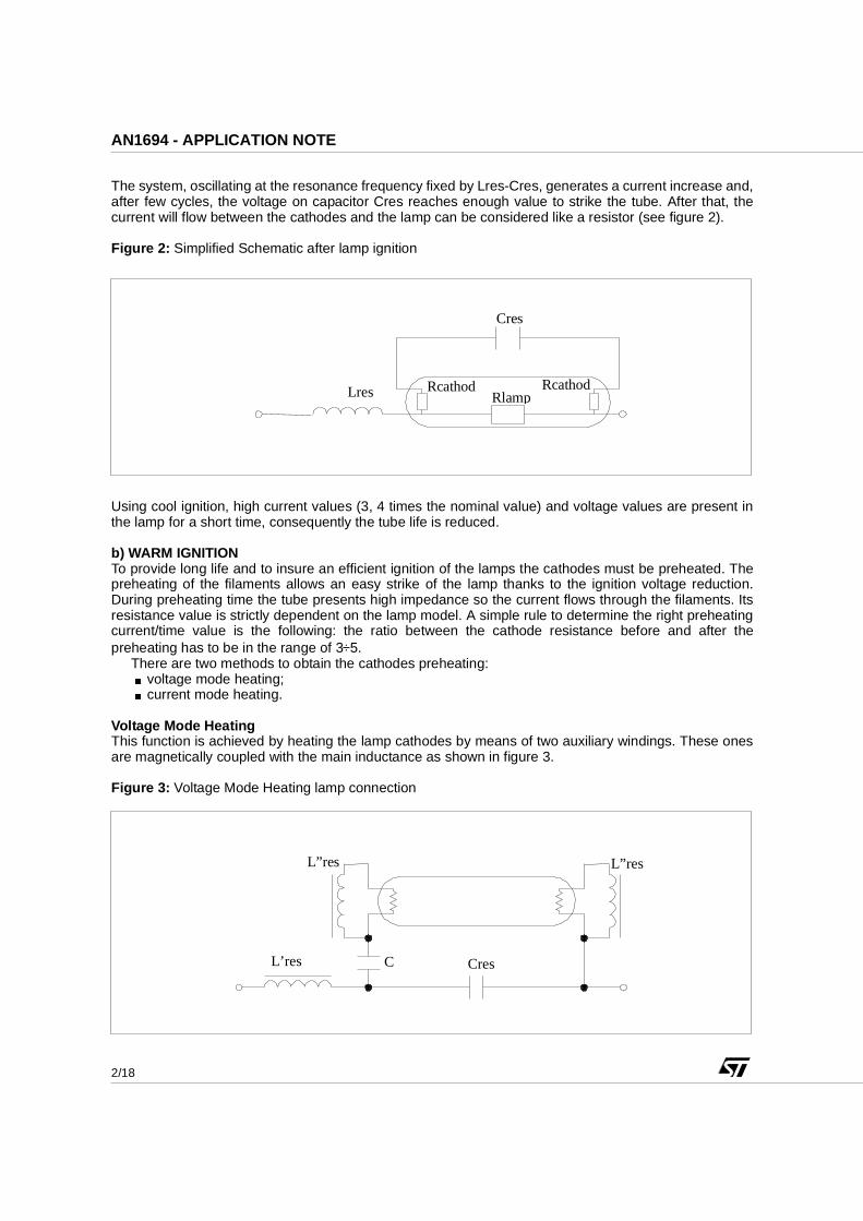
The system, oscillating at the resonance frequency fixed by Lres-Cres, generates a current increase and,after few cycles, the voltage on capacitor Cres reaches enough value to strike the tube. After that, thecurrent will flow between the cathodes and the lamp can be considered like a resistor (see figure 2).
Figure 2: Simplified Schematic after lamp ignition
Using cool ignition, high current values (3, 4 times the nominal value) and voltage values are present inthe lamp for a short time, consequently the tube life is reduced.
b) WARM IGNITIONTo provide long life and to insure an efficient ignition of the lamps the cathodes must be preheated. Thepreheating of the filaments allows an easy strike of the lamp thanks to the ignition voltage reduction.During preheating time the tube presents high impedance so the current flows through the filaments. Itsresistance value is strictly dependent on the lamp model. A simple rule to determine the right preheatingcurrent/time value is the following: the ratio between the cathode resistance before and after thepreheating has to be in the range of 3÷5.
There are two methods to obtain the cathodes preheating:< voltage mode heating;< current mode heating.
Voltage Mode HeatingThis function is achieved by heating the lamp cathodes by means of two auxiliary windings. These onesare magnetically coupled with the main inductance as shown in figure 3.
Figure 3: Voltage Mode Heating lamp connection
Rcathod Rlamp
Rcathod
Cres
Lres
L’res
L”res
Cres C
L”res
3/18
AN1694 - APPLICATION NOTE
During the preheating phase, the lamp can be considered an open circuit, the current flows through L’resand Cres. The voltage across L’res is transferred to the secondary windings L”res, generating a currentheating the cathodes. The primary current value is related to the half bridge working frequency, so thepreheating frequency is chosen according to the tube specs (rms current/time).The capacitor Cres must be chosen considering that, during the preheating, the voltage across it must belower than the ignition voltage. At the end of the preheating phase, when the system moves the workingfrequency towards the steady state frequency, the voltage on Cres will increase allowing an easierignition.
Current Mode HeatingThe Current mode heating is obtained similarly to the voltage mode heating but in this case the currentthat heats the cathodes is the same that flows in the resonant inductor Lres. Some typical solutions arereported below.
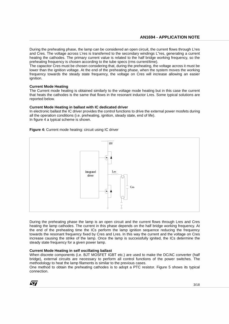
Current Mode Heating in ballast with IC dedicated driverIn electronic ballast the IC driver provides the control functions to drive the external power mosfets duringall the operation conditions (i.e. preheating, ignition, steady state, end of life).In figure 4 a typical scheme is shown.
Figure 4: Current mode heating: circuit using IC driver
During the preheating phase the lamp is an open circuit and the current flows through Lres and Cresheating the lamp cathodes. The current in this phase depends on the half bridge working frequency. Atthe end of the preheating time the ICs perform the lamp ignition sequence reducing the frequencytowards the resonant frequency fixed by Cres and Lres. In this way the current and the voltage on Cresincrease causing the strike of the lamp. Once the lamp is successfully ignited, the ICs determine thesteady state frequency for a given power lamp.
Current Mode Heating in self oscillating ballastWhen discrete components (i.e. BJT MOSFET IGBT etc.) are used to make the DC/AC converter (halfbridge), external circuits are necessary to perform all control functions of the power switches. Themethodology to heat the lamp filaments is similar to the previous cases.One method to obtain the preheating cathodes is to adopt a PTC resistor. Figure 5 shows its typicalconnection.
Integrated driver
HV
Lres
Cres

4/18
AN1694 - APPLICATION NOTE
Figure 5: Preheating circuit using PTC
Referring to figure 5 the following relationship between the capacitors has to be respected:
Cres>C’res>C”res (1)
At start up, when the PTC is cold, it can be considered as a short circuit (see figure 6), the circuit workingfrequency is determined by C’res and Lres (we can neglect Cres). During the preheating the currentflows through the PTC and C’res heats both the cathodes and the PTC at the same time. The value ofC’res must be chosen in order to avoid high voltage on the lamp and consequent switch on (the voltageacross PTC is negligible).
Figure 6: Equivalent circuit when PTC is a short circuit
When the PTC is hot (end of preheating) its resistance increases until it can be assumed as an opencircuit (see figure 7).
Figure 7: Equivalent circuit when PTC is an open circuit
PTC
C’’ res
C’res
Lres
Lres
C’’ res
C’res
Lres
C’res
C’’ res
5/18
AN1694 - APPLICATION NOTE
In this case the current flows through the series formed by C’’res and C’res. According to (1) theequivalent capacitance (C’’res series C’res) across the lamp becomes lower than the initial value (C’res)increasing the capacitive reactance and allowing the tube ignition.After the ignition, C’’res C’res and PTC can be considered a high impedance in parallel to the tube, thus itscontribute can be neglected.
3 END OF LIFE (EOL) PROTECTIONThe ballast shall not impair safety when operating under abnormal and fault conditions. Abnormalconditions are classified (European Standard) as reported below:
< lamp not inserted;< the lamp does not start because one of the two cathodes is broken;< the lamp does not start although the cathodes are intact (EOL);< the lamp operates, but one of the cathodes is de-activated or broken (rectifying effect).
Third condition is a typical EOL situation and it is verified when the gas inside the tube is exhausted.During the start-up phase, if the lamp doesn’t strike, very high current will flow in the circuit withdangerous high voltage appearing across the tube. This anomaly can be damaging on base materialresulting also dangerous for the operator that must replace the tube. For these reasons a protectionagainst faults is necessary. Since during the EOL condition high values of current and voltage are present in the circuit, two methodscan be adopted in order to detect it:
1) current sensing detection;2) voltage sensing detection.
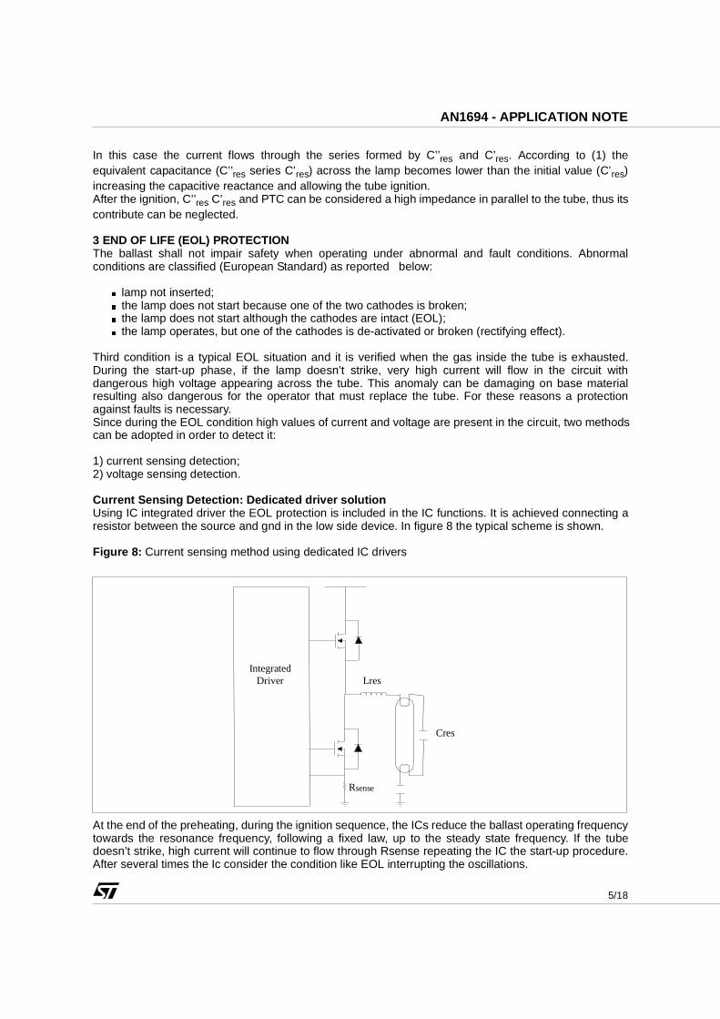
Current Sensing Detection: Dedicated driver solutionUsing IC integrated driver the EOL protection is included in the IC functions. It is achieved connecting aresistor between the source and gnd in the low side device. In figure 8 the typical scheme is shown.
Figure 8: Current sensing method using dedicated IC drivers
At the end of the preheating, during the ignition sequence, the ICs reduce the ballast operating frequencytowards the resonance frequency, following a fixed law, up to the steady state frequency. If the tubedoesn’t strike, high current will continue to flow through Rsense repeating the IC the start-up procedure.After several times the Ic consider the condition like EOL interrupting the oscillations.
Rsense
Integrated Driver
Cres
Lres

6/18
AN1694 - APPLICATION NOTE
Current Sensing Method: Discrete solutionUsing a circuit with discrete components the current sensing is realized in the same way as the previoussolution. In this case the voltage on Rsense drives an external circuit (timer plus latch). The latch, forexample, can be realized connecting two transistors in SCR configuration (see figure 9).
Figure 9: Current sensing method using discrete components
When the capacitor voltage reaches the latch threshold it is activated switching-off the low side device.The latch will keep in off–state the half bridge until the main voltage is present.
Voltage Sensing MethodAnother way to realize the EOL function is to detect the voltage across the lamp. In figure 10 a schemewith external components is shown.
Figure 10: Voltage sensing method connection using discrete components
SW1
SW2
Latch Rsense
Lres
driver sw1
driver sw2
HV
HV
driver
driver
HV
HV
Latch
Lres
Cres
SW1
SW2

7/18
AN1694 - APPLICATION NOTE
During the EOL phase, the protection circuit detects the over-voltage condition and activates the latchstopping the oscillation in the ballast. Using this method the rectifying effect can also be detectedbecause no over-current is present in the circuit but only over-voltage is generated across the tube.
4 BALLAST CIRCUIT BASED ON VK05CFL The proposed ballast, based on VK05CFL, drives removable tubes realizing the preheating and the endof life functions without the use of PTC and high voltage components with system reliability increasing.
4.1 ELECTRICAL SCHEME
In figure 11 the electrical scheme is reported. The demo-board can be adapted to different needs bysimple modifications i.e.: USA input voltage, EU input voltage, preheating function or not.
Figure11: VK05CFL demo-board electrical scheme
+ C0
C2 3 4 1
2 CFL C4
R13
R5
C5 VK05CFL
VK05CFL
D5 1N4148
R11C11
C7
C9 R9
R6
C6
D6 1N4148 R8
R12 C12
C8 C13
R7
L1
Q1 Q2
C15 R15
R16 C16
D7 1N4148
R14 Dz1 R17
D2 1N4007
D4 1N4007
D1 1N4007
D3 1N4007
+ C1
R0 C3
J5 jumper
J4 jumper
N 110V
230V
J6 jumper
J1 Jumper
Lres
EOL PROTECTION
8/18
AN1694 - APPLICATION NOTE
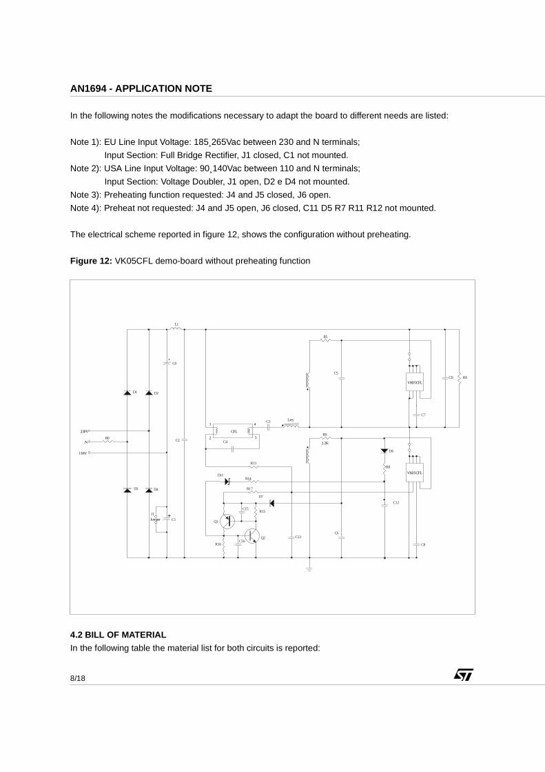
In the following notes the modifications necessary to adapt the board to different needs are listed:
Note 1): EU Line Input Voltage: 185¸265Vac between 230 and N terminals;
Input Section: Full Bridge Rectifier, J1 closed, C1 not mounted.
Note 2): USA Line Input Voltage: 90¸140Vac between 110 and N terminals;
Input Section: Voltage Doubler, J1 open, D2 e D4 not mounted.
Note 3): Preheating function requested: J4 and J5 closed, J6 open.
Note 4): Preheat not requested: J4 and J5 open, J6 closed, C11 D5 R7 R11 R12 not mounted.
The electrical scheme reported in figure 12, shows the configuration without preheating.
Figure 12: VK05CFL demo-board without preheating function
4.2 BILL OF MATERIAL
In the following table the material list for both circuits is reported:
+ C0
C2 3 4 1
2 CFL C4
R13
R5
C5 VK05CFL
VK05CFL
C7
C9 R9
R6 2.2K
C6
D6 R8
C12
C8 C13
L1
Q1
Q2
C15 R15
R16 C16
D7
R14 Dz1 R17
D2
D4
D1
D3
+C1
R0 C3
N 110V
230V
J1 Jumper
Lres
9/18
AN1694 - APPLICATION NOTE
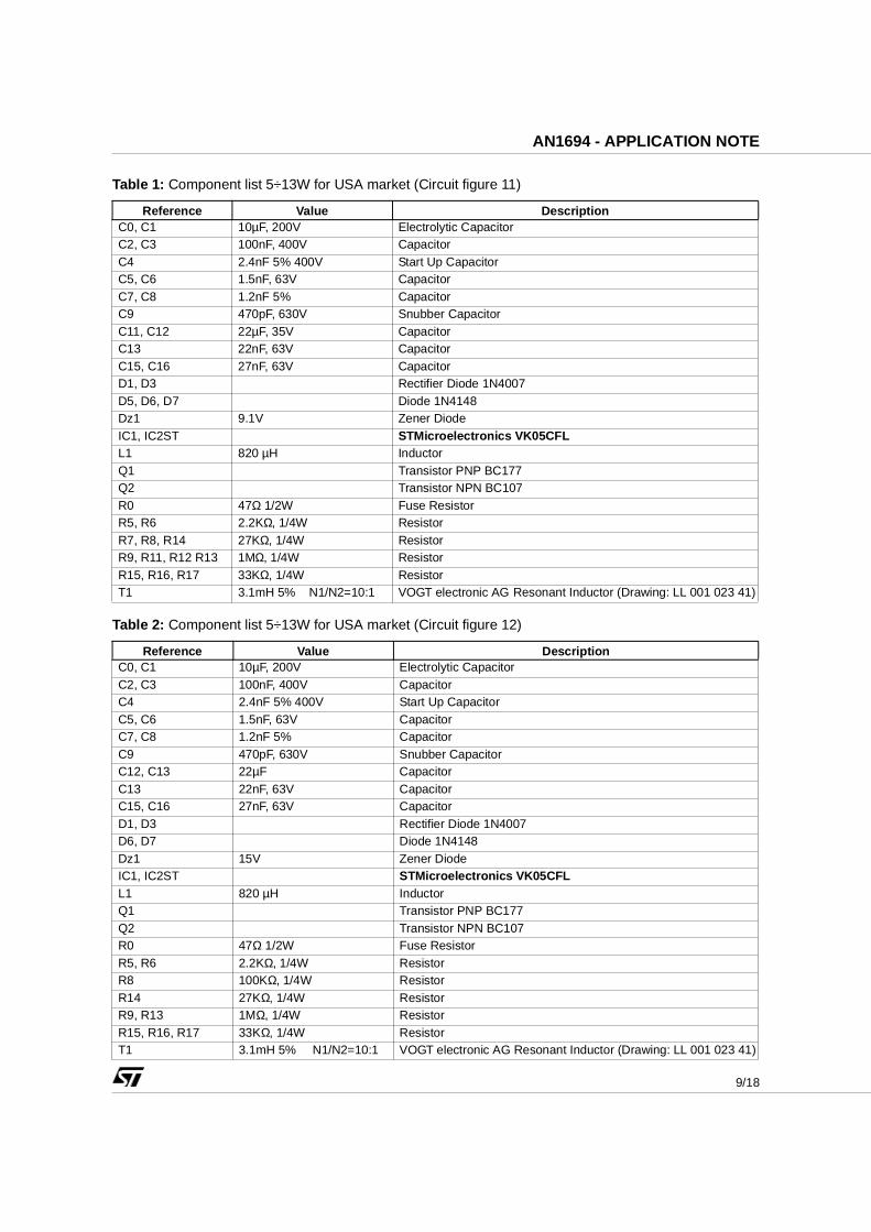
Table 1: Component list 5÷13W for USA market (Circuit figure 11)
Table 2: Component list 5÷13W for USA market (Circuit figure 12)
Reference Value DescriptionC0, C1 10µF, 200V Electrolytic CapacitorC2, C3 100nF, 400V CapacitorC4 2.4nF 5% 400V Start Up CapacitorC5, C6 1.5nF, 63V CapacitorC7, C8 1.2nF 5% CapacitorC9 470pF, 630V Snubber CapacitorC11, C12 22µF, 35V CapacitorC13 22nF, 63V CapacitorC15, C16 27nF, 63V CapacitorD1, D3 Rectifier Diode 1N4007D5, D6, D7 Diode 1N4148Dz1 9.1V Zener DiodeIC1, IC2ST STMicroelectronics VK05CFLL1 820 µH InductorQ1 Transistor PNP BC177Q2 Transistor NPN BC107R0 47Ω 1/2W Fuse ResistorR5, R6 2.2KΩ, 1/4W ResistorR7, R8, R14 27KΩ, 1/4W ResistorR9, R11, R12 R13 1MΩ, 1/4W ResistorR15, R16, R17 33KΩ, 1/4W ResistorT1 3.1mH 5% N1/N2=10:1 VOGT electronic AG Resonant Inductor (Drawing: LL 001 023 41)
Reference Value DescriptionC0, C1 10µF, 200V Electrolytic CapacitorC2, C3 100nF, 400V CapacitorC4 2.4nF 5% 400V Start Up CapacitorC5, C6 1.5nF, 63V CapacitorC7, C8 1.2nF 5% CapacitorC9 470pF, 630V Snubber CapacitorC12, C13 22µF CapacitorC13 22nF, 63V CapacitorC15, C16 27nF, 63V CapacitorD1, D3 Rectifier Diode 1N4007D6, D7 Diode 1N4148Dz1 15V Zener DiodeIC1, IC2ST STMicroelectronics VK05CFLL1 820 µH InductorQ1 Transistor PNP BC177Q2 Transistor NPN BC107R0 47Ω 1/2W Fuse ResistorR5, R6 2.2KΩ, 1/4W ResistorR8 100KΩ, 1/4W ResistorR14 27KΩ, 1/4W ResistorR9, R13 1MΩ, 1/4W ResistorR15, R16, R17 33KΩ, 1/4W ResistorT1 3.1mH 5% N1/N2=10:1 VOGT electronic AG Resonant Inductor (Drawing: LL 001 023 41)

10/18
AN1694 - APPLICATION NOTE
Table 3: Component list 5÷13W for European market (Circuit figure 11)
Table 4: Component list 5÷13W for European market (Circuit figure 12)
Reference Value DescriptionC0 3.3µF, 380V Electrolytic CapacitorC2, C3 100nF, 400V CapacitorC4 2.4nF 5% 400V Start Up CapacitorC5, C6 1.5nF, 63V CapacitorC7, C8 1.2nF 5% CapacitorC9 470pF, 630V Snubber CapacitorC11, C12 22µF, 35V CapacitorC13 22nF, 63V CapacitorC15, C16 27nF, 63V CapacitorD1, D2, D3, D4 Rectifier Diode 1N4007D5, D6, D7 Diode 1N4148Dz1 9.1V Zener DiodeIC1, IC2ST STMicroelectronics VK05CFLL1 820 µH InductorQ1 Transistor PNP BC177Q2 Transistor NPN BC107R0 47Ω 1/2W Fuse ResistorR5, R6 2.2KΩ, 1/4W ResistorR7, R8, R14 27KΩ, 1/4W ResistorR9, R11, R12, R13 1MΩ, 1/4W ResistorR15, R16, R17 33KΩ, 1/4W ResistorT1 3.1mH 5% N1/N2=10:1 VOGT electronic AG Resonant Inductor (Drawing: LL 001 023 41)
Reference Value DescriptionC0 3.3µF, 380V Electrolytic CapacitorC2, C3 100nF, 400V CapacitorC4 2.4nF 5% 400V Start Up CapacitorC5, C6 1.5nF, 63V CapacitorC7, C8 1.2nF 5% CapacitorC9 470pF, 630V Snubber CapacitorC12 27µF CapacitorC13 22nF, 63V CapacitorC15, C16 27nF, 63V CapacitorD1, D2, D3, D4 Rectifier Diode 1N4007D6, D7 Diode 1N4148Dz1 15V Zener DiodeIC1, IC2ST STMicroelectronics VK05CFLL1 820 µH InductorQ1 Transistor PNP BC177Q2 Transistor NPN BC107R0 47Ω 1/2W Fuse ResistorR5, R6 2.2KΩ, 1/4W ResistorR8 150KΩ, 1/4W ResistorR9, R13 1MΩ, 1/4W ResistorR14 27KΩ, 1/4W ResistorR15, R16, R17 33KΩ, 1/4W ResistorT1 3.1mH 5% N1/N2=10:1 VOGT electronic AG Resonant Inductor (Drawing: LL 001 023 41)
11/18
AN1694 - APPLICATION NOTE
4.3 CIRCUIT DESCRIPTION
About the circuit description the used topology is the same already described in the AN1546, thereforethis paragraph will only deal with the procedure used to realize the preheating and the EOL functions.
Preheating Description
The preheating function is realized modifying the ballast operating frequency. In the VK05CFL device it ispossible to set the working frequency by external capacitor (see datasheet). If, by external addedcomponents, the capacitor current changes, also the working frequency will change.
It is important to highlight that the circuit has to be applied to both sides in order to guarantee the fiftypercent duty cycle.
This function is described referring to the electrical scheme shown in figure 11.
At the beginning both VK05CFL are OFF. As soon as the voltage on C13, connected to DC bus by resistorR2, reaches the internal diac threshold (~30V) the low side device is switched ON starting the oscillations.
The voltage drop on Lp is transferred to the secondary windings confirming the "ON" state for the low sidedevice and the "OFF" state for the high side. In this phase the tube is an open circuit and the resonancefrequency is fixed by Lres-C4.
The preheating circuit made by diode D5 (6), resistors R7 (8) - R11 (12) and capacitor C11 (12) injectscurrent into the frequency capacitor any time the filtered secondary winding voltage becomes positive, thisuntil the capacitor C11 (12) is charged at the maximum secondary voltage, in this way the preheating timeis defined. The capacitor cannot lose its charge thanks the presence of the diode D5 (6). The resistor R7(8) fix the value of the current add to the frequency capacitors, consequently the working frequency isfixed.
Looking at the formulae (2) it is possible to notice that the frequency is not stable during the wholepreheating phase due to the drop increasing on C11(12) with consequent injected current reduction.
Ipreh=(Vsec-VC11 (12))/R7 (8) (2)
Where: Ipreh = Injected current into the frequency capacitor during the preheating phase.
Vsec = Filtered secondary input voltage.
VC11 = Voltage across the preheating capacitor.
In the preheating frequency calculation this current has to be added to the VK05 Iosc.
The preheating conditions are:
- Working frequency higher than the resonance frequency
- Voltage across the tube lower than ignition voltage
Ipreh decrease increasing the capacitor voltage, for this reason, to maintain the lamp current moreconstant possible for longer time, several microfarad are requested, in any case near the end of thepreheating time this current variation appears moving the working frequency towards the resonancefrequency guaranteeing the tube ignition.
After this phase the preheating circuit has no effect (Ipreh=0A) and the ballast frequency become thesteady-state frequency fixed by Iosc.
The resistor R11 (12) is necessary to discharge the capacitor C11 (C12) when the lamp is switched off inorder to have a new preheating at the successive switch on. The time constant factor can be chosen earlyenough to take into account the tube temperature, having different preheating times for differentconsecutive switchings ON/OFF.
12/18
AN1694 - APPLICATION NOTE
Eol Description
Referring to the electrical scheme, the EOL condition is detected monitoring the voltage across thecapacitor C12.
When the tube fails the ignition or it starts to work in rectification mode, the voltage on the primaryinductance increases with respect to the steady state value, consequently by the secondary windings thisvariation is transferred on the preheating capacitor increasing its average voltage as to the same onereached during the preheating phase, therefore, when the Dz1 voltage is reached, the latch circuit isactivated switching off the converter. The latch acts on the sec pin by means of D7 diode in order tomaintain its voltage (~1.5V) lower than the ON threshold. The latch sustain current comes from theresistor R13, it is connected to the tube cathode to reset the circuit when the tube is substituted.
To avoid diac restart during the latch off phase also the diac capacitor voltage is maintained lower than theon threshold.
During the EOL phase, the preheating circuit controls, by Ton reduction, the current in the converter, inorder to avoid reaching very high values.
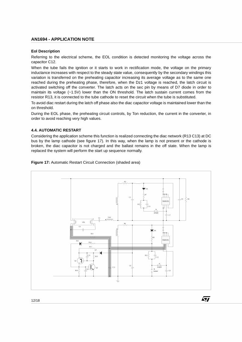
4.4. AUTOMATIC RESTART
Considering the application scheme this function is realized connecting the diac network (R13 C13) at DCbus by the lamp cathode (see figure 17). In this way, when the lamp is not present or the cathode isbroken, the diac capacitor is not charged and the ballast remains in the off state. When the lamp isreplaced the system will perform the start up sequence normally.
Figure 17: Automatic Restart Circuit Connection (shaded area)
3 4 1
2 CFL C4
R13
R5
C5 VK05CFL
VK05CFL
D5
R11C11
C7
C9 R9
R6
C6
D6 R8
R12 C12
C8 C13
R7
Q1 Q2
C15 R15
R16 C16
D7
R14 Dz1 R17
C3
J5 jumper
J4 jumper
J6 jumper
Lres
13/18
AN1694 - APPLICATION NOTE
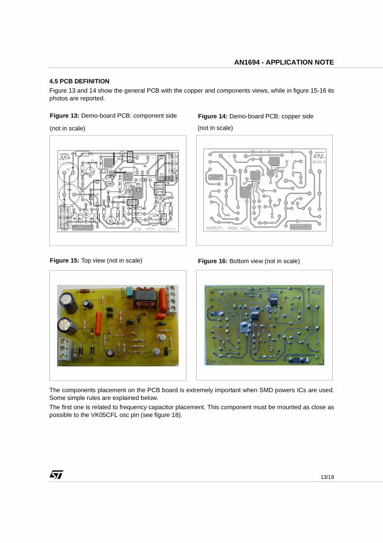
4.5 PCB DEFINITION
Figure 13 and 14 show the general PCB with the copper and components views, while in figure 15-16 itsphotos are reported.
The components placement on the PCB board is extremely important when SMD powers ICs are used.Some simple rules are explained below.
The first one is related to frequency capacitor placement. This component must be mounted as close aspossible to the VK05CFL osc pin (see figure 18).
Figure 13: Demo-board PCB: component side
(not in scale)
Figure 14: Demo-board PCB: copper side
(not in scale)
Figure 15: Top view (not in scale) Figure 16: Bottom view (not in scale)
14/18
AN1694 - APPLICATION NOTE
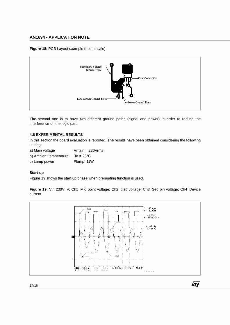
Figure 18: PCB Layout example (not in scale)
The second one is to have two different ground paths (signal and power) in order to reduce theinterference on the logic part.
4.6 EXPERIMENTAL RESULTS
In this section the board evaluation is reported. The results have been obtained considering the followingsetting:
a) Main voltage Vmain = 230Vrms
b) Ambient temperature Ta = 25°C
c) Lamp power Plamp=11W
Start-up
Figure 19 shows the start up phase when preheating function is used.
Figure 19: Vin 230V=V; Ch1=Mid point voltage; Ch2=diac voltage; Ch3=Sec pin voltage; Ch4=Devicecurrent
Power Ground TraceEOL Circuit Ground Trace
Secondary VoltageGround Trace
Cosc Connection
Power Ground TraceEOL Circuit Ground Trace
Secondary VoltageGround Trace
Cosc Connection
Power Ground TraceEOL Circuit Ground Trace
Secondary VoltageGround Trace
Cosc Connection
Ch2
Ch1
Ch3
Ch4

15/18
AN1694 - APPLICATION NOTE
When the low side diac pin voltage reaches 30V the device is switched ON and the converter starts tooscillate. An integrated diode discharges the diac capacitor keeping its voltage low during the steadystate.
The preheating oscillation frequency is 67kHz, it is higher than the system resonance frequency fres (withLres=3.1mH, and Cres=2.4nF => fres=58kHz).
In figure 20 the current during the preheating and the voltage across the cathode is shown. Thepreheating time is lower than 1s and the cathode voltage at the end of pre-heating phase is about 3 timeshigher than initial value ensuring the cathodes heating.
Figure 20: Pre-heating phase - Ch4=Cathodes current; Ch3=Cathode voltage
In figure 21 the start up phase using cool ignition method is shown (Electric scheme figure 12). The devicecurrent (Ch4) increases rapidly and after few cycles its value is able to generate, across the start-upcapacitor, an over-voltage sufficient to ignite the tube.
Figure 21: Ch1=Mid point voltage; Ch4=Primary inductance current
Ch3
Ch4
C h4
Ch1
16/18
AN1694 - APPLICATION NOTE
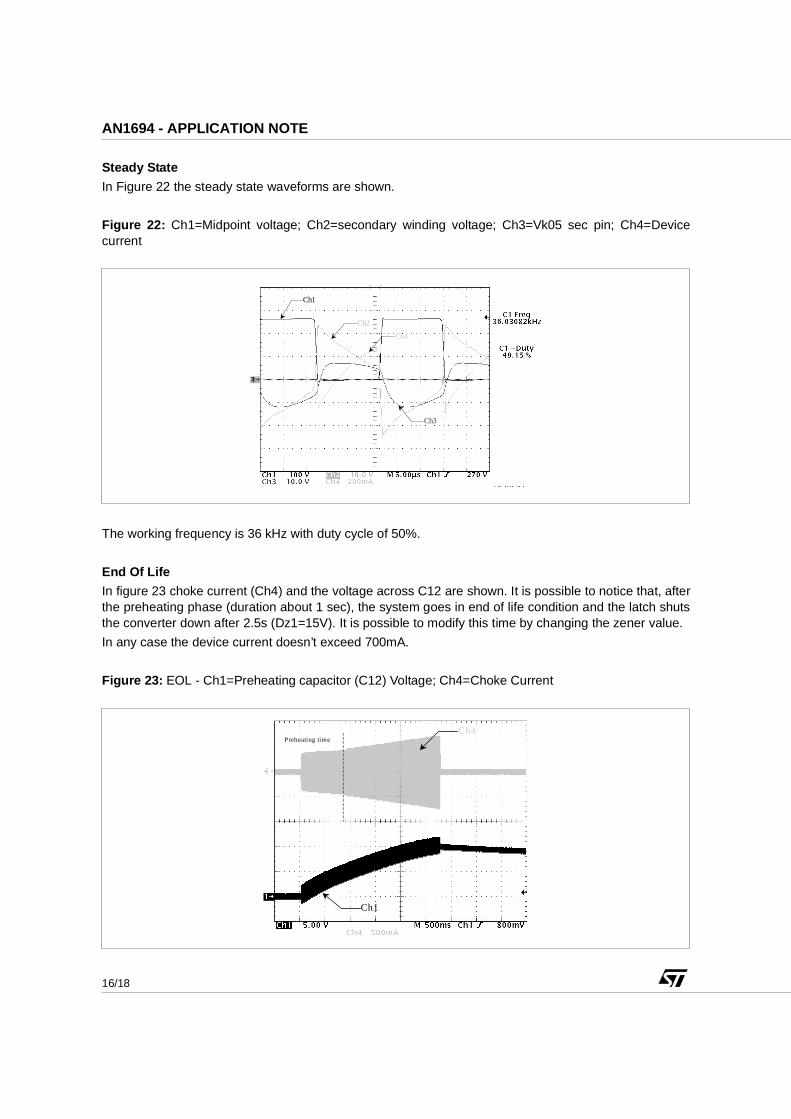
Steady State
In Figure 22 the steady state waveforms are shown.
Figure 22: Ch1=Midpoint voltage; Ch2=secondary winding voltage; Ch3=Vk05 sec pin; Ch4=Devicecurrent
The working frequency is 36 kHz with duty cycle of 50%.
End Of Life
In figure 23 choke current (Ch4) and the voltage across C12 are shown. It is possible to notice that, afterthe preheating phase (duration about 1 sec), the system goes in end of life condition and the latch shutsthe converter down after 2.5s (Dz1=15V). It is possible to modify this time by changing the zener value.
In any case the device current doesn’t exceed 700mA.
Figure 23: EOL - Ch1=Preheating capacitor (C12) Voltage; Ch4=Choke Current
Ch2
Ch1
Ch3
Ch4
Ch1
Ch4 Preheating time

17/18
AN1694 - APPLICATION NOTE
Figure 24 shows the converter switch-off when the latch is activated.
Figure 24: Ch1=Midpoint voltage; Ch2=Voltage on the base of Q2; Ch3=Vk05 sec pin; Ch4=Devicecurrent
In figure 25 the main converter waveforms showing the EOL intervention in the circuit without preheatingfunction are reported.
Figure 25: Ch2= Voltage on the base of Q2, Ch3= Voltage on (C12) capacitor
Lamp Absence
When the lamp is not present in the circuit, the system can’t oscillate because of the absence of thecathodes open the circuit.
C h1
C h3
C h4
C h2
Ch3
Ch2

18/18
AN1694 - APPLICATION NOTE
Broken Cathodes
At start up if only one of the two cathodes are broken the half bridge cannot oscillate because the currentpath is interrupted.
Thermal Behavior
The thermal board analysis has been performed measuring the real devices temperature in application.The copper area dedicated to both devices to sink the heat is 100 mm2.
The temperature has been measured using thermocouples K type soldered on top of the packages.
The measurements have been performed driving a 13W tube at two different ambient temperatures: 55°Cand 75°C. In the following table the results are summarized:
Table 5
The device power dissipation is lower than 200mW.
Information furnished is believed to be accurate and reliable. However, STMicroelectronics assumes no responsibility for the consequencesof use of such information nor for any infringement of patents or other rights of third parties which may results from its use. No license isgranted by implication or otherwise under any patent or patent rights of STMicroelectronics. Specifications mentioned in this publication aresubject to change without notice. This publication supersedes and replaces all information previously supplied. STMicroelectronics productsare not authorized for use as critical components in life support devices or systems without express written approval of STMicroelectronics.
The ST logo is a trademark of STMicroelectronics
2003 STMicroelectronics - Printed in ITALY- All Rights Reserved.
STMicroelectronics GROUP OF COMPANIESAustralia - Brazil - Canada - China - Finland - France - Germany - Hong Kong - India - Israel - Italy - Japan - Malaysia -
Malta - Morocco - Singapore - Spain - Sweden - Switzerland - United Kingdom - U.S.A.
http://www.st.com
Ta=55°C Tdevice=68°CTa=75°C Tdevice=93°C
Related Documents