An SIR Loaded Modified Dipole Antenna Deepak U.* 1 ,Roshna T.K. 2 , Sujith R. 3 , and Mohanan P. 4 1. Centre for Research in Electromagnetics and Antennas (CREMA), Department of Electronics, CUSAT Cochin-22, Kerala, India. 1. [email protected] 2. [email protected] 4. [email protected] 3. Angstrom Laboratory, Department of Engineering Sciences, Uppsala University, Box 534, SE-751 21 Uppsala, Sweden. [email protected] Abstract This paper proposes a novel compact coplanar dual band antenna for 2.4 & 5.2GHz ISM band applications. The antenna occupies an area of 25x9 mm 2 on an FR4 substrate of thickness 1.6mm and permittivity 4.3. A bended dipole gives the higher resonance and an SIR, electrically coupled to the dipole gives the lower resonance. The 2:1 VSWR impedance bandwidth of the proposed antenna is 90MHz for the first resonance around 2.4GHz and 2.5GHz for the second resonance. The radiation patterns are nearly omnidirectional. The maximum measured gain is 3.33dBi and 5.9dBi for 2.46GHz and 5.42GHz respectively. 1. Introduction The 2.4GHz and 5.2 GHz ISM bands are two very common and widely used application bands. Wireless local area networks, many other wireless devices like wireless printers, blue tooth etc. utilizes the 2.4/5.2GHz band. Many devices require multiband capability to comply with IEEE 802.11, 802.11a, 802.11b, 802.11g, ETSI HiperLAN1, HiperLAN2 standards. Many attempts have been done on the antenna fabrication in these two bands. A dual band slot antenna using an L shaped microstrip line feeding on FR4 gives a peak gain of 3.2 and 5.5 dBi in the two bands with a footprint of 40X60X1 mm 3 [1]. A hook shaped monopole antenna with a footprint of 26x10x1 mm 3 works at 2.4/5GHz range with a peak gain of 1.4dBi and 3.37dBi respectively [2]. A spiral patch antenna on an FR4 substrate with an overall size of 26.9x25.9x0.8 mm 3 works at 2.4/5GHz band with a peak gain of 1.04dBi and 4.04dBi respectively [3]. A novel design is presented in this paper, where a modified planar dipole antenna along with a parasitic element is used for achieving a dual band operation. The total footprint of the antenna is very small and a considerably good gain is achieved with a reduced complexity to the structure. A bended SIR is used as the parasitic element. Here the dipole itself acts as a coplanar ground plane at 2.4GHz for the SIR. The antenna is fabricated on a common, easily available FR4 substrate used for printed circuit board fabrication. A desirable bandwidth with -10dB reflection coefficient in both lower and higher band is achieved. 2. Antenna Design & Geometry The geometry of the proposed antenna is shown in fig. 1. The antenna occupies an overall area of 25 X 9 mm 2 on an FR4 substrate of permittivity 4.3 and thickness 1.6mm. A planar dipole antenna is initially designed and then modified. The dipole of 2mm thickness is been bend with an inner radius of 7mm. This dipole corresponds to a length of λ g /2 at 5 GHz. A stepped impedance resonator (SIR), with a dimension L 1 , L 2 , L 3 , W 1 and W 2 is utilized as a parasitic element to the dipole. The SIR is resonating at 2.4GHz with a length of λ g /2. The design and optimization of the antenna is done with the help of Ansoft HFSS. The antenna design started with the design of a planar dipole Figure 1 Geometry of the proposed antenna (W 1 =2mm, L 1 =6.7mm, L 2 =9.62mm, L 3 =7.3mm, R 1 =7mm, R 2 =9mm, C=0.4mm, D=0.9mm, H=4.1mm, G=1mm) 978-1-4673-5225-3/14/$31.00 ©2014 IEEE

Welcome message from author
This document is posted to help you gain knowledge. Please leave a comment to let me know what you think about it! Share it to your friends and learn new things together.
Transcript
An SIR Loaded Modified Dipole Antenna
Deepak U.*1,Roshna T.K.2, Sujith R.3, and Mohanan P.4
1. Centre for Research in Electromagnetics and Antennas (CREMA), Department of Electronics, CUSAT
Cochin-22, Kerala, India. 1. [email protected] 2. [email protected] 4. [email protected]
3. Angstrom Laboratory, Department of Engineering Sciences, Uppsala University, Box 534, SE-751 21 Uppsala, Sweden. [email protected]
Abstract
This paper proposes a novel compact coplanar dual band antenna for 2.4 & 5.2GHz ISM band applications.
The antenna occupies an area of 25x9 mm2 on an FR4 substrate of thickness 1.6mm and permittivity 4.3. A bended dipole gives the higher resonance and an SIR, electrically coupled to the dipole gives the lower resonance. The 2:1 VSWR impedance bandwidth of the proposed antenna is 90MHz for the first resonance around 2.4GHz and 2.5GHz for the second resonance. The radiation patterns are nearly omnidirectional. The maximum measured gain is 3.33dBi and 5.9dBi for 2.46GHz and 5.42GHz respectively.
1. Introduction
The 2.4GHz and 5.2 GHz ISM bands are two very common and widely used application bands. Wireless local area networks, many other wireless devices like wireless printers, blue tooth etc. utilizes the 2.4/5.2GHz band. Many devices require multiband capability to comply with IEEE 802.11, 802.11a, 802.11b, 802.11g, ETSI HiperLAN1, HiperLAN2 standards. Many attempts have been done on the antenna fabrication in these two bands. A dual band slot antenna using an L shaped microstrip line feeding on FR4 gives a peak gain of 3.2 and 5.5 dBi in the two bands with a footprint of 40X60X1 mm3[1]. A hook shaped monopole antenna with a footprint of 26x10x1 mm3 works at 2.4/5GHz range with a peak gain of 1.4dBi and 3.37dBi respectively [2]. A spiral patch antenna on an FR4 substrate with an overall size of 26.9x25.9x0.8 mm3 works at 2.4/5GHz band with a peak gain of 1.04dBi and 4.04dBi respectively [3].
A novel design is presented in this paper, where a modified planar dipole antenna along with a parasitic
element is used for achieving a dual band operation. The total footprint of the antenna is very small and a considerably good gain is achieved with a reduced complexity to the structure. A bended SIR is used as the parasitic element. Here the dipole itself acts as a coplanar ground plane at 2.4GHz for the SIR. The antenna is fabricated on a common, easily available FR4 substrate used for printed circuit board fabrication. A desirable bandwidth with -10dB reflection coefficient in both lower and higher band is achieved.
2. Antenna Design & Geometry
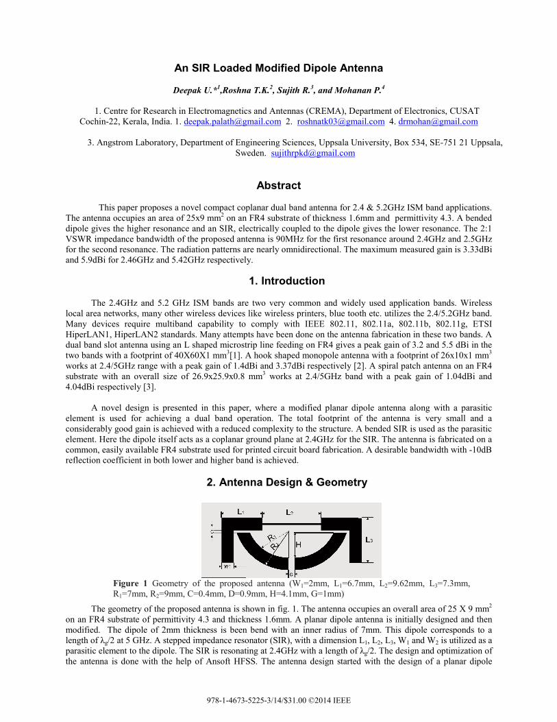
The geometry of the proposed antenna is shown in fig. 1. The antenna occupies an overall area of 25 X 9 mm2
on an FR4 substrate of permittivity 4.3 and thickness 1.6mm. A planar dipole antenna is initially designed and then modified. The dipole of 2mm thickness is been bend with an inner radius of 7mm. This dipole corresponds to a length of λg/2 at 5 GHz. A stepped impedance resonator (SIR), with a dimension L1, L2, L3, W1 and W2 is utilized as a parasitic element to the dipole. The SIR is resonating at 2.4GHz with a length of λg/2. The design and optimization of the antenna is done with the help of Ansoft HFSS. The antenna design started with the design of a planar dipole
Figure 1 Geometry of the proposed antenna (W1=2mm, L1=6.7mm, L2=9.62mm, L3=7.3mm, R1=7mm, R2=9mm, C=0.4mm, D=0.9mm, H=4.1mm, G=1mm)
978-1-4673-5225-3/14/$31.00 ©2014 IEEE
antenna in the 5-6GHz frequency band. A parasitic strip, i.e. a uniform impedance resonator (UIR), is then top loaded to the dipole in order to achieve the lower resonance. For improving the performance, a bend is introduced in the dipole, and then the bended dipole is top loaded with an UIR, which introduces a new lower resonance, with a poor impedance matching. For improving the impedance matching, a 90 degree bend is introduced in the UIR. The UIR is replaced with an SIR for getting compactness to the structure.
3. Results And Discussion
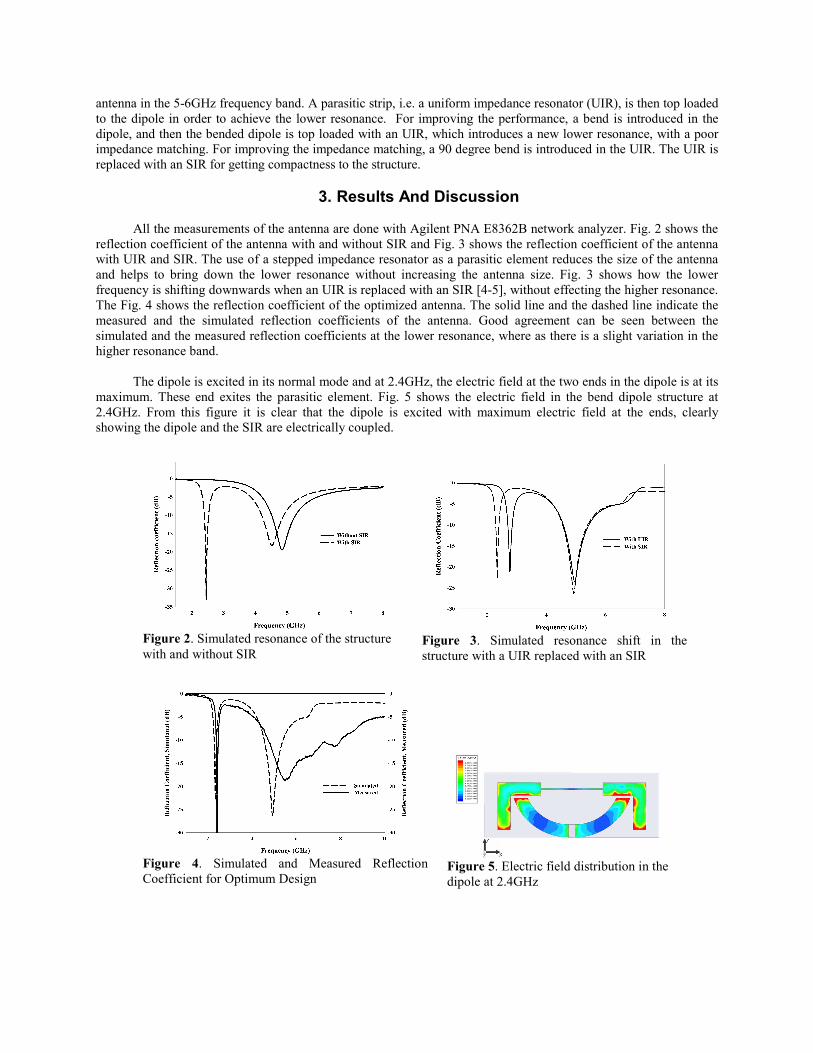
All the measurements of the antenna are done with Agilent PNA E8362B network analyzer. Fig. 2 shows the reflection coefficient of the antenna with and without SIR and Fig. 3 shows the reflection coefficient of the antenna with UIR and SIR. The use of a stepped impedance resonator as a parasitic element reduces the size of the antenna and helps to bring down the lower resonance without increasing the antenna size. Fig. 3 shows how the lower frequency is shifting downwards when an UIR is replaced with an SIR [4-5], without effecting the higher resonance. The Fig. 4 shows the reflection coefficient of the optimized antenna. The solid line and the dashed line indicate the measured and the simulated reflection coefficients of the antenna. Good agreement can be seen between the simulated and the measured reflection coefficients at the lower resonance, where as there is a slight variation in the higher resonance band.
The dipole is excited in its normal mode and at 2.4GHz, the electric field at the two ends in the dipole is at its
maximum. These end exites the parasitic element. Fig. 5 shows the electric field in the bend dipole structure at 2.4GHz. From this figure it is clear that the dipole is excited with maximum electric field at the ends, clearly showing the dipole and the SIR are electrically coupled.
Figure 5. Electric field distribution in the dipole at 2.4GHz
Figure 4. Simulated and Measured Reflection Coefficient for Optimum Design
Figure 3. Simulated resonance shift in the structure with a UIR replaced with an SIR
Figure 2. Simulated resonance of the structure with and without SIR

Fig. 6 shows the surface current distribution in the antenna of both the bands. In the SIR at 2.4GHz, the current along the Y direction on either side is antiparallel and will cancel at far field, leaving behind a net current in the X direction. In the bend dipole at 5GHz, when the surface current is resolved in to X and Y components, the Y components on either side of the dipole is antiparallel and will cancel at far field, leaving behind a next current in the X direction. This results in the polarization of the antenna along X direction for both the bands and it is experimentally verified.
The radiation pattern of the antenna is shown in the Fig. 7. The pattern is nearly omnidirectional in both the
bands. The Fig. 8 shows the gain plot of the antenna in both the bands. In the 2.4GHz band it gives a near uniform gain with an average gain of 2.8dBi and a peak gain of 3.33dBi. In the 5-6GHz band the gain is not flat. Here the average gain is 3.6 dBi with a peak gain of 5.9 dBi. In the 2.4GHz band measured efficiency is 91.2% and in the 5-6GHz band it is 94%. The efficiency in both the bands are measured using wheeler cap method [6]. The antenna shows a 2:1 VSWR bandwidth of 90MHz in the 2.4GHz band from 2.38GHz to 2.47GHz and 2.5GHz in the 5-6GHz band from 4.75GHz to 7.3GHz covering the entire band.
Figure 6b. Surface Current on SIR and bend dipole at 5.2GHz
Figure 7b. Radiation pattern at 5.2GHz
Figure 7a. Radiation pattern at 2.4GHz
Figure 8b. Gain of the antenna in 5GHz band
Figure 8a. Gain of the antenna in 2.4GHz band
Figure 6a. Surface current on SIR and bend dipole at 2.4GHz
4. Conclusion
In this paper a novel compact coplanar dual band antenna is proposed and investigated. The antenna resonates at 2.4 & 5-6GHz bands with a 2:1 VSWR bandwidth of 90MHz and 2.5GHz respectively. The average gain of the antenna is 2.8dBi and 3.6dBi at 2.4GHz and 5GHz with a peak gain of 3.33dBi and 5.9dBi respectively inspite of its small size. The antenna shows a nearly omnidirectional radiation pattern. The efficiency in both the bands is 91.2% and 94% respectively.
5. Acknowledgment
The authors acknowledge the University Grants Commission (UGC) and Department of Science and Technology (DST), Government of India for the financial assistance.
6. References
1. W. Ren, Compact dual band antenna for 2.4/5GHz WLAN application, Progress In Electromagnetics Research B, Vol. 8, 319-327, 2008.
2. Chi-Hun Lee and Seong-Ook park, A compact printed hook shaped monopole antenna for 2.4/5Ghz WLAN applications, Microwaveand Optical Technology Letters, Vol. 48, No.2, February 2006..
3. JoongHan Yoon, Fabrication and measurement of modified spiral patch antenna for use as a triple band(2.4GHz/5GHz) antenna, Microwaveand Optical Technology Letters, Vol. 48, No. 7, July 2006.
4. Chi-Feng Chen, Ting-Yi Huang, Chi-Ping Chou and Ruey Bee Wu, ‘‘Microstrip diplexers design with common resonator sections for compact size, but high isolation’’ IEEE Trans Microwave Theory Tech, Vol. 54, No. 5, pp 1945-1952, May 2006.
5. Arnaud Vena, Etenne Perret and smail Tedjini, “Chipless RFID tag using hybrid coding technique”, IEEE Trans
Microwave Theory Tech, Vol. 59, No.12 pp 3356-3364, December 2011.
6. H. A. Wheeler, “The radiationsphere around a small antenna”, Proc. IRE, 47, 8, pp. 1325-1333, Aug. 1959.
Related Documents