1 © 2012 Wiley-VCH Verlag GmbH & Co. KGaA, Weinheim wileyonlinelibrary.com Supercapacitors An Overview of the Applications of Graphene-Based Materials in Supercapacitors Yi Huang, Jiajie Liang, and Yongsheng Chen* Due to their unique 2D structure and outstanding intrinsic physical properties, such as extraordinarily high electrical conductivity and large surface area, graphene- based materials exhibit great potential for application in supercapacitors. In this review, the progress made so far for their applications in supercapacitors is reviewed, including electrochemical double-layer capacitors, pseudo-capacitors, and asymmetric supercapacitors. Compared with traditional electrode materials, graphene- based materials show some novel characteristics and mechanisms in the process of energy storage and release. Several key issues for improving the structure of graphene-based materials and for achieving better capacitor performance, along with the current outlook for the field, are also discussed. 1. Introduction . . . . . . . . . . . . . . . . . . . . . . . . . . 2 2. Preparation of Graphene-Based Materials used for Supercapacitor Electrodes . . . . . . 3 3. Graphene-Based EDLCs: . . . . . . . . . . . . . . . 3 4. Graphene-Conducting Polymer-Composite- Based Pseudo-capacitors . . . . .. . . . . . . . 16 5. Pseudo-capacitors Based on Graphene– (Metal Oxide) Composites. . . . . . . . . . . . . 20 6. Graphene-Based Asymmetric Supercapacitors . . . . . . . . . . . . . . . . . . . . . . . . . .. . . . . . . . . 25 7. Conclusion and Outlook . . . . . . . . . . . . . . 27 From the Contents small 2012, DOI: 10.1002/smll.201102635

Welcome message from author
This document is posted to help you gain knowledge. Please leave a comment to let me know what you think about it! Share it to your friends and learn new things together.
Transcript

Supercapacitors
An Overview of the Applications of Graphene-Based Materials in Supercapacitors Yi Huang , Jiajie Liang , and Yongsheng Chen *
1© 2012 Wiley-VCH Verlag GmbH & Co. KGaA, Weinheim wileyonlinelibrary.com
Due to their unique 2D structure and outstanding intrinsic physical properties, such as extraordinarily high electrical conductivity and large surface area, graphene-based materials exhibit great potential for application in supercapacitors. In this review, the progress made so far for their applications in supercapacitors is reviewed, including electrochemical double-layer capacitors, pseudo-capacitors, and asymmetric supercapacitors. Compared with traditional electrode materials, graphene-based materials show some novel characteristics and mechanisms in the process of energy storage and release. Several key issues for improving the structure of graphene-based materials and for achieving better capacitor performance, along with the current outlook for the fi eld, are also discussed.
1. Introduction . . . . . . . . . . . . . . . . . . . . . . . . . . 2
2. Preparation of Graphene-Based Materials used for Supercapacitor Electrodes . . . . . . 3
3. Graphene-Based EDLCs: . . . . . . . . . . . . . . . 3
4. Graphene-Conducting Polymer-Composite-Based Pseudo-capacitors . . . . .. . . . . . . . 16
5. Pseudo-capacitors Based on Graphene–(Metal Oxide) Composites. . . . . . . . . . . . . 20
6. Graphene-Based Asymmetric Supercapacitors . . . . . . . . . . . . . . . . . . . . . . . . . .. . . . . . . . . 25
7. Conclusion and Outlook . . . . . . . . . . . . . . 27
From the Contents
small 2012, DOI: 10.1002/smll.201102635

Y. Huang et al.reviews
DOI: 10.1002/smll.201102635
Prof. Y. Huang , [+] Dr. J. J. Liang , [+] Prof. Y. S. Chen Key Laboratory of Functional Polymer Materials and Centre for Nanoscale Science and TechnologyInstitute of Polymer ChemistryCollege of ChemistryNankai University300071, Tianjin, China E-mail: [email protected][+] Y. L. and J.J.L. have contributed equally to this review.
1. Introduction
Graphene, a one-atom-thick 2D single layer of sp 2 -bonded
carbon, has been considered as the basic construction mate-
rial for carbon materials of all other dimensionalities. [ 1–3 ] As a
result of this unique structural property, graphene is provided
with a series of prominent intrinsic chemical and physical fea-
tures, such as strong mechanical strength ( ∼ 1 TPa), [ 4 , 5 ] extraor-
dinarily high electrical and thermal conductivity, [ 6–8 ] and large
surface area (2675 m 2 /g), [ 9 ] which may rival or even surpass
both single- and multi-walled carbon nanotubes. These out-
standing and intriguing features make this extremely versatile
carbon material promising for various practical applications,
including high-performance nanocomposites, [ 10 – 12 ] trans-
parent conducting fi lms, [ 6 , 7 , 13–16 ] sensors, [ 17 , 18 ] actuators, [ 19–22 ]
nanoelectronics, [ 23 , 24 ] and energy storage devices. [ 25–28 ] Sig-
nifi cantly, utilizing graphene as a supercapacitor electrode
material has become the focus of a considerable amount of
research in the fi eld of clean energy devices due to the ben-
efi cial combination of the excellent mechanical and electrical
properties and large surface area. [ 25–28 ]
The investigation of novel, low-cost, environmentally
friendly, and high-performance energy storage systems has
been under an ever increasing demand as a result of the
needs of modern society and emerging ecological concerns. [ 29 ]
Supercapacitors, also named electrochemical capacitors and
ultracapacitors, [ 30 , 31 ] are supposed to be a promising candi-
date for alternative energy storage devices as a result of their
high rate capability, pulse power supply, long cycle life, simple
principles, high dynamic sof charge propagation, and low
maintenance cost. [ 31–34 ] Supercapacitors store signifi cantly
higher amounts of energy density than the conventional die-
lectric capacitor, but they have a similar cell construction as
traditional capacitors except for the fact that the metal elec-
trodes are replaced by highly porous electrodes. [ 35 ] Further-
more, the shortage of other power sources, such as batteries
and fuel cells, could be complemented by supercapacitors,
because of their long cycle life and rapid charging and dis-
charging rate at high power densities. [ 34 ] Consequently, the
supercapacitor has continued to attract considerable atten-
tion from both scientists and engineers since it was demon-
strated and patented by General Electric [ 36 ] in 1957, and it
has generated great interest for a wide and growing range of
applications that require high power density such as energy
back-up systems, consumer portable devices, and electrical/
hybrid automobiles. [ 33 , 34 , 36–38 ]
Actually, based on the different energy storage mecha-
nisms, supercapacitors can be divided into two classes: 1) elec-
trochemical double-layer capacitors (EDLCs) which store
energy using the adsorption of both anions and cations and
2) pseudo-capacitors that store energy through fast surface
redox reactions. EDLCs, which are non-Faradaic ultracapaci-
tors, derive their performance from a so-called double-layer
capacitance. [ 39 , 40 ] The capacitance in these EDLC devices is
stored as a build-up of charge in the layers of the electrical
double-layer formed at the interface between a high-surface-
area electrode and an electrolyte. [ 39 , 40 ] Generally, porous
carbon materials such as activated carbon, [ 41 , 20 ] xerogels, [ 43 ]
carbon nanotubes (CNTs), [ 44–47 ] mesoporous carbon, [ 48 ] and
2 www.small-journal.com © 2012 Wiley-VCH V
carbide-derived carbons, [ 49 ] have been investigated for use
as electrodes in EDLCs. Extensive explorations have shown
that to achieve EDLCs with high performance, several factors
of the carbon-based materials are crucial: the specifi c surface
area (SSA), electrical conductivity, and pore size and distri-
bution. In most cases, although porous-carbon-based mate-
rials can obtain high SSA, the low conductivity of porous
carbon materials continues to restrict its application in high-
power-density supercapacitors. [ 50 ] As for CNTs, although
they possess high electrical conductivity and large SSA, CNT-
based supercapacitors still cannot meet acceptable perform-
ance, [ 44 , 51–53 ] which is probably due to the observed contact
resistance between the electrode and current collector. [ 48 , 50 ]
Moreover, the intrinsic impurities of CNTs from catalysts
and amorphous carbon and their high cost have hampered
their practical application in supercapacitors to date. Hence,
great efforts are still spent on developing novel carbon-based
supercapacitor electrode materials with an overall high per-
formance. Fortunately, the emergence of graphene provides
an excellent alternative to past EDLC electrode materials.
Compared with traditional porous carbon materials, graphene
has very high electrical conductivity, large surface area, and
profuse interlayer structure. Hence graphene-based materials
are hugely favorable for their application to EDLCs. [ 27 ]
In contrast to EDLCs, pseudo-capacitors store energy
through a Faradic process, involving fast and reversible redox
reactions between electrolyte and electro-active materials on
the electrode surface. [ 40 ] The most widely explored electro-
active materials include three types: a) transition metal oxides
or hydroxides, [ 54 , 55 ] such as ruthenium oxide, manganese
oxide, and nickel hydroxide; b) conducting polymers, [ 39 , 41 , 56 ]
such as polyaniline, polypyrrole, and polythiophene; and
c) materials possessing oxygen- and nitrogen-containing sur-
face functional groups. [ 40 ] Compared with EDLCs, pseudo-
capacitors can achieve much higher pseudo-capacitance than
the EDL capacitance. Nevertheless, further practical applica-
tions of these electro-active materials to pseudo-capacitors
are still limited by the low power density that arises from the
poor electrical conductivity restricting fast electron transport,
and by the lack of a pure cycling stability owing to the easily
damaged structure of the materials during the redox process.
Hence, to resolve these problems, carbon-based materials
with high electrical conductivity and large SSA are usu-
ally used as the backbone materials to combine with these
active materials for pseudo-capacitor electrodes. Given the
many excellent properties of graphene, such as high elec-
trical conductivity and high mechanical strength, graphene is
erlag GmbH & Co. KGaA, Weinheim small 2012, DOI: 10.1002/smll.201102635

Applications of Graphene-Based Materials in Supercapacitors
Yongsheng Chen graduated from the Universi-
ty of Victoria with a Ph.D. degree in chemistry
in 1997 and then joined the University of Ken-
tucky and the University of California at Los
Angeles for postdoctoral studies from 1997 to
1999. From 2003, he has been a Chair Profes-
sor at Nankai University. His main research
interests include: 1) carbon-based nanomateri-
als, including carbon nanotubes and graphene;
2) organic and polymeric functional materials,
and 3) energy devices including organic photo-
voltaics and supercapacitor. He has published
over 130 peer-reviewed papers with over 6000
citations and has over 20 patents.
Yi Huang received his B.S. (1996) in Polymer
Science and Engineering and Ph.D. (2001)
in Materialogy from Sichuan University. He
then spent two years as a postdoctoral fellow
at the Department of Chemical Engineering
of Tsinghua University. Since 2004, he has
been an Associate Professor of Chemistry at
Nankai University. His research interests fo-
cus on controlled synthesis and application of
carbon nanomaterials (graphene and carbon
nanotubes), functional polymer materials, and
nano-composites and -devices. He has pub-
lished over 60 peer-reviewed journal articles
with over 1500 citations.
Jiajie Liang received his B.S. from the De-
partment of Chemistry of Nankai University
(2006) and his Ph.D. from the Institute of
Polymer Chemistry of Nankai University
under the direction of Prof. Yongsheng Chen
(2011). Currently, he is a postdoctoral fellow
in the group of Prof. Qibing Pei in the De-
partment of Materials Science & Engineering
at the University of California, Los Angeles.
His research is focused on the applications
of graphene-based materials, including
graphene-based actuators, high-performance
composites, and electronic devices.
considered as one of the most suitable substrate materials for
preparing pseudo-capacitor electrodes.
In this review, we will summarize the progress made so
far in graphene-based supercapacitors by considering to the
two basic kinds of supercapacitors (EDLCs and pseudo-
capacitors) and their hybrid supercapacitors (which function
with simultaneous EDLC and pseudo-capacitor mechanisms);
we will discuss their mechanisms and explore their effective
ways to achieve high supercapacitor performance.
2. Preparation of Graphene-Based Materials used for Supercapacitor Electrodes
Several effective and facile approaches have been developed
to synthesize graphene-based materials, including: 1) epi-
taxial growth and chemical vapor deposition (CVD) growth
of graphene on SiC and matched metal surfaces; [ 14 , 57–59 ]
2) micromechanical exfoliation of graphite (using atomic
force microscopy (AFM) cantilevers or adhesive tape); [ 5 , 7 , 60 ]
3) exfoliation of graphite in organic solvents; [ 61 ] 4) substrate-
free gas-phase synthesis of graphene platelets in a microwave
plasma reactor; [ 62 ] 5) arc-discharge synthesis of multi-layered
graphene; [ 63 ] 6) reduction from graphene oxide (GO), which
is synthesized by either the Brodie, [ 64 ] Staudenmaier, [ 65 ] or
Hummers methods, [ 66 ] and variations of these chemical exfo-
liation methods. Although the number of different fabrication
methods continually increases, [ 58 ] the most important method
to prepare graphene-based materials that can be used for
supercapacitor electrodes is still the chemical exfoliation of
graphite to graphene oxide, followed by controllable reduc-
tion of graphene oxide to graphene. [ 11 , 13 , 67 ] This is probably
attributed to the following reasons: 1) graphene oxide can be
facilely prepared through the chemical exfoliation method
at large-scale with relatively low cost, which is the fi rst con-
dition required for the practical application of graphene-
based supercapacitors. 2) The oxygen-containing functional
groups on the surface allow for graphene oxide to be easily
chemically modifi ed and processed in solution state. 3) Var-
ious routes can be used to reduce GO to graphene, restore
the intrinsic SSA and electrical conductivity of graphene,
and construct graphene-based nanostructures with desir-
able channel size, which are all favorable for supercapacitor
applications. Thus, as we will discuss in the following sec-
tions, exploring novel ways to reduce GO to graphene and to
design graphene-based materials with high SSA and conduc-
tivity are the main-stream routes, but these are not the only
way to construct high-performance graphene-based superca-
pacitor electrodes.
3. Graphene-Based EDLCs:
3.1. Graphene-Based Electrode Materials Prepared through Chemical Reduction of Graphene Oxide
Suspending graphene oxide sheets in water followed by
reducing them (with reducing agent such as hydrazine
© 2012 Wiley-VCH Verlag Gmbsmall 2012, DOI: 10.1002/smll.201102635
hydrate) is a simple yet versatile method to prepare
reduced graphene-based materials (RGM). [ 68 ] Ruoff and co-
workers [ 38 ] fi rst explored graphene-based EDLCs utilizing
this kind of chemically modifi ed graphene (CMG) as elec-
trode materials. Although the individual graphene sheets par-
tially agglomerated into particles approximately 15–25 μ m
in diameter during the reduction process, the relatively high
specifi c surface area of the graphene-based material (GBM)
aggregation (705 m 2 /g) still allows these CMG electrodes to
have high electrochemical performance ( Figure 1 ). Large
specifi c capacitance values of 135 and 99 F/g for aqueous
and organic electrolytes, respectively, were achieved by these
CMG materials. Moreover, low variation of specifi c capaci-
tance for increasing voltage scan rates was also observed for
the CMG electrodes due to the high conductivity of the CMG
( ∼ 200 S/m). Given that there is still much potential for the
improvement of the SSA and conductivity of graphene-based
3www.small-journal.comH & Co. KGaA, Weinheim

Y. Huang et al.reviews
Figure 1 . Graphene-based EDLCs utilizing CMG as electrode materials. a) Scanning electron microscopy (SEM) image of CMG particle, b) transmission electron microscopy (TEM) image showing individual graphene sheets extending from the CMG particle, c) low- and high- (inset) magnifi cation SEM images of the CMG particle electrode, and d) schematic of test cell assembly. Reproduced with permission. [ 38 ] Copyright 2008, American Chemical Society.
materials, this original work and encouraging results indicate
that graphene-based materials are extremely promising can-
didates for EDLC ultracapacitors.
Although GO can be well dispersed in aqueous solu-
tion as individual sheets, direct reduction of GO in solu-
tion will result in irreversibly precipitated agglomerates, [ 68 ]
which behave no differently than particulate graphite plate-
lets having relatively low surface area. [ 69 ] To avoid this irre-
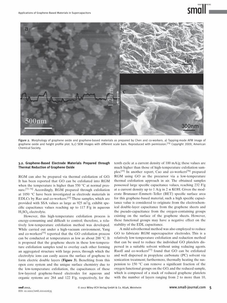
versible re-stacking of graphene, Chen and co-workers [ 70 ]
exploited a gas–solid reduction process to prepare the
graphene-based materials, and fabricated supercapacitor
devices using these GBM as electrode materials. While the
graphene sheets still exist as aggregated and crumpled sheets
closely associated with each other and form a continuous
conducting network, this GBM indeed has a low degree
of agglomeration ( Figure 2 ) compared with the graphene
material obtained in a solution reduction process. [ 38 , 68 ] Thus,
in this structure or morphology, the electrolyte ion should
have better accessibility, not only penetrated in the outer
region of the solids but also in the inner region compared
with conventional carbon materials used in capacitors. Con-
sequently, both ends of a broad range of graphene sheets
could be exposed to the electrolyte and thus contribute to
the capacitance. As a result, a maximum specifi c capacitance
of 205 F/g with a measured power density of 10 kW/kg at
4 www.small-journal.com © 2012 Wiley-VCH
an energy density of 28.5 W h/kg in an aqueous electrolyte
solution has been achieved by this GBM electrode. In addi-
tion, the supercapacitor devices exhibit excellent long cycle
life along with ∼ 90% specifi c capacitance retained after 1200
cycle tests.
In addition to hydrazine hydrate, hydrobromic acid is
another widely used agent that can reduce GO. Ma and co-
workers [ 71 ] reported that adding hydrobromic acid into a
GO solution reduces it to graphene-based materials. Since
hydrobromic acid is a weak reductant, some oxygen func-
tional groups, which are relatively stable for electrochemical
systems, remain in reduced GO. Therefore, the oxygen-con-
taining groups on the graphene surface not only can promote
the wettability of the reduced GO and facilitate the pen-
etration of the aqueous electrolyte, but they also introduce
pseudo-capacitive effects. As a result, at the current density
of 0.2 A/g, the maximum specifi c capacitance values reach
348 F/g in the 1 m aqueous H 2 SO 4 . Surprisingly, the capaci-
tance of reduced GO does not degrade but increase continu-
ously until the 2000th cycle. More specifi cally, it passes 125%
of the initial capacitance after 1800 cycles and is still above
120% after 3000 cycles. These may be due to the fact that
the reduction of the residual oxygen by the cycling measure-
ments continuously improves the capacitive properties before
the 1800th cycle.
Verlag GmbH & Co. KGaA, Weinheim small 2012, DOI: 10.1002/smll.201102635
Applications of Graphene-Based Materials in Supercapacitors
Figure 2 . Morphology of graphene oxide and graphene-based materials as prepared by Chen and co-workers. a) Tapping-mode AFM image of graphene oxide and height profi le plot. b,c) SEM images with different scale bars. Reproduced with permission. [ 70 ] Copyright 2009, American Chemical Society.
3.2. Graphene-Based Electrode Materials Prepared through Thermal Reduction of Graphene Oxide
RGM can also be prepared via thermal exfoliation of GO.
It has been reported that GO can be exfoliated into RGM
when the temperature is higher than 550 ° C at normal pres-
sure. [ 72–74 ] Accordingly, RGM prepared through exfoliation
at 1050 ° C have been investigated as electrode materials in
EDLCs by Rao and co-workers. [ 35 ] These samples, which are
provided with SSA values as large as 925 m 2 /g, exhibit spe-
cifi c capacitance values reaching up to 117 F/g in aqueous
H 2 SO 4 electrolyte.
However, this high-temperature exfoliation process is
energy-consuming and diffi cult to control; therefore, a rela-
tively low-temperature exfoliation method was developed.
While carried out under a high-vacuum environment, Yang
and co-workers [ 75 ] reported that the GO exfoliation process
can be conducted at temperatures as low as about 200 ° C. It
is proposed that the graphene sheets in these low-tempera-
ture exfoliation samples tend to overlay each other forming
an aggregated structure with large pores, through which the
electrolyte ions can easily access the surface of graphene to
form electric double layers ( Figure 3 ). Benefi ting from this
open core system and the unique surface chemistry due to
the low-temperature exfoliation, the capacitances of these
few-layered graphene-based electrodes for aqueous and
organic systems are 264 and 122 F/g, respectively, for the
© 2012 Wiley-VCH Verlag GmbHsmall 2012, DOI: 10.1002/smll.201102635
tenth cycle at a current density of 100 mA/g; these values are
much higher than those of high-temperature exfoliation sam-
ples. [ 35 ] In another report, Cao and co-workers [ 76 ] prepared
RGM using GO as the precursor via a low-temperature
thermal exfoliation approach in air. The obtained samples
possessed large specifi c capacitance values, reaching 232 F/g
at a current density up to 1 A/g in 2 m KOH. Given the mod-
erate Brunauer–Emmett–Teller (BET) specifi c surface area
for this graphene-based material, such a high specifi c capaci-
tance value is considered to originate from the electrochem-
ical double-layer capacitance from the graphene sheets and
the pseudo-capacitance from the oxygen-containing groups
existing on the surface of the graphene sheets. However,
these functional groups may have a negative effect on the
stability of the EDL capacitance.
A mild solvothermal method was also employed to reduce
GO to fabricate RGM supercapacitor electrodes. This is a
relatively low-temperature exfoliation and reduction method
that can be used to reduce the individual GO platelets dis-
persed in a suitable solvent without using reducing agents.
Ruoff and co-workers [ 77 ] found that GO can be exfoliated
and well dispersed in propylene carbonate (PC) solvent via
sonication treatment; furthermore, thermally heating the sus-
pension to 150 ° C can remove a signifi cant fraction of the
oxygen functional groups on the GO, and the reduced sample,
which is composed of a stack of reduced graphene platelets
with the number of layers ranging from 2 to more than 10,
5www.small-journal.com & Co. KGaA, Weinheim

Y. Huang et al.reviews
6
Figure 3 . Structural characterization of a graphite oxide and graphene. a) Thermogravimetric and differential scanning calorimetry (TG-DSC) curves of a GO sample. b) X-ray diffraction (XRD) patterns of graphite, GO, and the graphene resulting from exfoliation. c–g) SEM images of G-200, G-400, G-200-HT, and G-HT (G-200, G-300, and G-400 correspond to the thermally treated samples at 200, 300,and 400 ° C respectively; G-200-HT corresponds to heat-treating G-200 in a preheated furnace at 1000 ° C; G-HT corresponds to a sample prepared by a normally employed high-temperature exfoliation method at 1000 ° C). Reproduced with permission. [ 75 ] Copyright 2009, American Chemical Society.
in PC remains a homogeneous black suspension. Although
reduced under relatively low temperature, such reduced
graphene platelets still showed a conductivity value as high
as 5230 S/m. Since commercial ultracapacitors commonly use
tetraethylammonium tetrafl uoroborate (TEA BF 4 ) in PC for
the electrolyte, TEA BF 4 could be simply added to this PC/
RGM suspension with the resulting slurry then used for the
EDLC electrodes. A high capacitance of 112 F/g was achieved
by this RGM in a PC-based electrolyte, which compares
favorably with the performance of other electrode materials
(80–120 F/g) using PC-based electrolytes. [ 78 ] In another work,
Wong and co-workers [ 79 ] dispersed GO in dimethyl forma-
mide (DMF) and thermally treated the dispersion at a mod-
erate temperature (150 ° C), which allows fi ne control of the
density of functional groups. Importantly, such surface func-
tionalities on graphene introduce high pseudo-capacitance,
good wetting properties, and acceptable electrical conduc-
tivity to these graphene-based materials. They found that the
specifi c capacitance between 0 and 0.5 V is much larger than
that between 0.6 and 0.8 V. These results together with cyclic
voltammetry (CV) curves suggests that EDLC is responsible
for the capacitance between 0.6 and 0.8 V and pseudo-capac-
itance becomes the dominant contributor at lower potentials
www.small-journal.com © 2012 Wiley-VCH V
( Figure 4 ). A specifi c capacitance up to 276 F/g was gained
based on functionalized graphene at a discharge current of
0.1 A/g in a 1 m H 2 SO 4 electrolyte. Surprisingly, although the
surface functional groups provide high pseudo-capacitance
due to the redox reactions, the graphene-based materials still
show good cycling stability. The reason behind this is that the
pseudo-capacitance mainy arose from the the dominating
fraction of carbonyl and hydroxyl groups on the graphene
surface, but not the carboxyl groups which sometimes lead
to degradation of carbon materials. [ 80 , 81 ] The carboxyl groups
can be effi ciently removed, but the carbonyl and hydroxyl
groups can be retained due to their high thermal stability
during the solvothermal reaction; a high pseudo-capacitance
is thus obtained without sacrifi cing the cycling stability.
As a convenient and rapid heating source, microwave
irradiation annealing has also been used to prepare exfoli-
ated graphite (EG) from a wide range of graphite interca-
lation compounds (GICs) due to the microwave absorbing
properties of graphene-based materials. [ 82–86 ] On the basis
of this technique, Ruoff and co-workers [ 82 ] prepared RGM
by facilely and effi ciently treating GO powder in a com-
mercial microwave oven. This as-prepared sample consisted
of crumpled, “worm-like”, few-layer thick ( Figure 5 ), and
erlag GmbH & Co. KGaA, Weinheim small 2012, DOI: 10.1002/smll.201102635

Applications of Graphene-Based Materials in Supercapacitors
Figure 4 . Capacitive properties of functionalized graphene materials (fG). a) CV curves of fG at different scan rates; b) galvanostatic charge/discharge curves of fG at different charge/discharge currents. 1 M H 2 SO 4 was used as electrolyte. Reproduced with permission. [ 79 ] Copyright 2011, American Chemical Society.
electronically conductive graphitic sheets. They showed a spe-
cifi c surface area of 463 m 2 /g, which make it a promising elec-
trode material for EDLC applications. Therefore, employing
the microwave-exfoliated RGM as an electrode material
in an EDLC, specifi c capacitance values as high as 191 F/g
were obtained with KOH electrolyte. This simple microwave
irradiation annealing process provides a promising route for
the scalable and cost-effective production of graphene-based
electrode materials.
© 2012 Wiley-VCH Verlag Gmb
Figure 5 . Structure characterization of GO. Optical photos of GO before (aas-prepared microwave-exfoliated GO by microwave irradiation with a higexfoliated GO with electron diffraction pattern. e) X-ray photoelectron specReproduced with permission. [ 82 ] Copyright 2010, Elsevier Ltd.
small 2012, DOI: 10.1002/smll.201102635
3.3. Graphene-Based Electrode Materials Prepared through Graphene-Based Hydrogel
In most cases, graphene-based electrodes prepared simply
through chemical and/or thermal reduction still do not have
suffi ciently large pores for the facile access of the electro-
lyte. [ 8 , 36 , 87–89 ] As a result, the high specifi c capacitances and
energy densities were in most studies only achievable by
charging/discharging at low current densities ( < 1 A/g) or
7www.small-journal.comH & Co. KGaA, Weinheim
) and after (b) treatment in a microwave oven for 1 min. c) SEM image of h-magnifi cation SEM image in the inset. d) TEM image of the microwave-troscopy (XPS) C 1s spectra of GO and microwave-exfoliated GO (MEGO).
Y. Huang et al.reviews
8
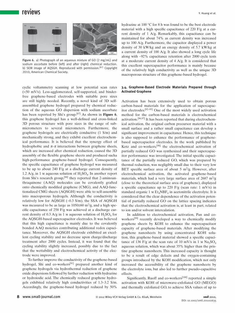
Figure 6 . a) Photograph of an aqueous mixture of GO (2 mg/mL) and sodium ascorbate before (left) and after (right) chemical reduction. b) SEM image of AQSGH. Reproduced with permission. [ 87 ] Copyright 2010, American Chemical Society.
cyclic voltammetry scanning at low potential scan rates
( < 50 mV/s). Less-agglomerated, self-supported, and binder-
free graphene-based electrodes with suitable pore sizes
are still highly needed. Recently, a novel kind of 3D self-
assembled graphene hydrogel prepared by chemical reduc-
tion of the aqueous GO dispersion with sodium ascorbate
has been reported by Shi's group. [ 87 ] As shown in Figure 6 ,
this graphene hydrogel has a well-defi ned and cross-linked
3D porous structure with pore sizes in the range of sub-
micrometers to several micrometers. Furthermore, the
graphene hydrogels are electrically conductive (1 S/m) and
mechanically strong, and they exhibit excellent electrochem-
ical performance. It is believed that the synergy effect of
hydrophobic and π – π interactions between graphene sheets,
which are increased after chemical reduction, caused the 3D
assembly of the fl exible graphene sheets and produced sucha
high-performance graphene-based hydrogel. Consequently,
the specifi c capacitance of graphene hydrogel was measured
to be up to about 240 F/g at a discharge current density of
1.2 A/g, in 1 m aqueous solution of H 2 SO 4 . In another report
from Shi's research group, [ 90 ] they reported that 2-aminoan-
thraquinone (AAQ) molecules can be covalently grafted
onto chemically modifi ed graphene (CMG), and AAQ-func-
tionalized CMG sheets (AQSGH) were able to self-assemble
into macroporous hydrogels. Although the conductivity is
relatively low for AQSGH ( ∼ 0.3 S/m), the SSA of AQSGH
was measured to be as large as 1050 ± 60 m 2 /g, and a high spe-
cifi c capacitance of 258 F/g was achieved at a discharge cur-
rent density of 0.3 A/g in 1 m aqueous solution of H 2 SO 4 for
the AQSGH-based supercapacitor electrodes. It was believed
that this high capacitance is mainly due to the covalently
bonded AAQ moieties contributing additional redox capaci-
tance. Moreover, the AQSGH electrode exhibited an excel-
lent cycling stability and no decrease upon charge/discharge
treatment after 2000 cycles. Instead, it was found that the
cycling stability slightly increased, possibly due to the fact
that the wettability and electrochemical activity of the elec-
trode were improved.
To further improve the conductivity of the graphene-based
hydrogel, Shi and co-workers [ 91 ] prepared another kind of
graphene hydrogels via hydrothermal reduction of graphene
oxide dispersions followed by further reduction with hydrazine
or hydroiodic acid. The chemically reduced graphene hydro-
gels exhibited relatively high conductivities of 1.3–3.2 S/m.
Accordingly, the graphene-based hydrogel reduced by 50%
www.small-journal.com © 2012 Wiley-VCH Ve
hydrazine at 100 ° C for 8 h was found to be the best electrode
material with a high specifi c capacitance of 220 F/g at a cur-
rent density of 1 A/g. Remarkably, this capacitance can be
maintained for about 74% as current density was increased
up to 100 A/g. Furthermore, the capacitor displayed a power
density of 30 kW/kg and an energy density of 5.7 kW/kg at
a current density of 100 A/g. It also showed a long cycle life
along with ∼ 92% capacitance retention after 2000 cycle tests
at a moderate current density of 4 A/g. It is considered that
this excellent supercapacitor performance is mainly because
of the relatively high conductivity as well as the unique 3D
macroporous structure of this graphene-based hydrogel.
3.4. Graphene-Based Electrode Materials Prepared through Activated Graphene
Activation has been extensively used to obtain porous
carbon-based materials for the application of supercapac-
itor electrodes. [ 92–95 ] One of the most widely used activation
method for the carbon-based materials is electrochemical
activation. [ 96 , 97 ] It has been reported that during electrochem-
ical activation, the original carbon precursor material with a
small surface and a rather small capacitance can develop a
signifi cant improvement in capacitance. Hence, this technique
is also supposed to enhance the performance of graphene-
based supercapacitor electrodes. In the work published by
Kotz and co-workers, [ 98 ] the electrochemical activation of
partially reduced GO was synthesized and their supercapac-
itor performance was investigated. The initial specifi c capaci-
tance of the partially reduced GO, which was prepared by
thermal reduction, was negligibly small due to their very low
BET specifi c surface area of about 5 m 2 /g. However, after
electrochemical activation, the activated graphene-based
materials, which had a very large surface area of 2687 m 2 /g
(close to the theoretical surface area of graphene), displayed
a specifi c capacitance up to 220 F/g (scan rate: 1 mV/s) in
standard organic 1 m Et 4 NBF 4 in acetonitrile electrolyte. It is
considered that the clear dependence of the activation poten-
tial of partially reduced GO on the lattice spacing indicates
that the electrochemical activation is, at least in part, related
to ion and/or solvent intercalation.
In addition to electrochemical activation, Pan and co-
workers [ 99 ] recently developed a way to chemically modify
graphene sheets by KOH to enhance the supercapacitaor
capacity of graphene-based materials. After modifying the
graphene nanosheets by using concentrated KOH solu-
tion, this graphene-based material showed a specifi c capaci-
tance of 136 F/g at the scan rate of 10 mV/s in 1 m Na 2 SO 4
aqueous solution, which was about 35% higher than the pris-
tine graphene nanosheets. This increased capacity is thought
to be a result of edge defects and the oxygen-containing
groups introduced by the KOH modifi cation, which not only
increased the accessibility of the graphene nanosheets by
the electrolyte ions, but also led to further pseudo-capacitive
effects.
Signifi cantly, Ruoff and co-workers [ 100 ] reported a simple
activation with KOH of microwave-exfoliated GO (MEGO)
and thermally exfoliated GO, to achieve SSA values of up to
rlag GmbH & Co. KGaA, Weinheim small 2012, DOI: 10.1002/smll.201102635

Applications of Graphene-Based Materials in Supercapacitors
Figure 7 . Graphene-based electrode materials prepared by activation of microwav-exfoliated GO. A) Schematic showing the microwave exfoliation/reduction of GO and the following chemical activation process. B) Low-magnifi cation SEM image of a 3D MEGO fragment. C) High-resolution SEM image of a different sample region. D) Annular dark fi eld scanning transmission electron microscopy (ADF-STEM) image of the same area as in (C), acquired simultaneously. E) High-resolution phase- contrast electron microscopy image of the thin edge of a MEGO fragment. Reproduced with permission. [ 100 ] Copyright 2011, the American Association for the Advancement of Science.
Figure 8 . Schematic of a) graphene sheets and b) nanoparticle-modifi ed graphene sheets in its dispersion and dry state. Reproduced with permission. [ 69 ] Copyright 2008, American Chemical Society.
3100 m 2 /g ( Figure 7 ). It is found that the activation process
etches the MEGO and generates a 3D distribution of what
are referred to as mesopores. Remarkably, the activation with
KOH yields a continuous 3D network of pores of extremely
small size, ranging from < 1 to 10 nm. Furthermore, although
the graphene sheets bend through high degrees of curvature,
the in-plane crystallinity is preserved. The supercapacitor
performance of the activated-MEGO (SSA = ∼ 2400 m 2 /g) in
1-butyl-3-methyl-imidazolium tetrafl uoroborate/acetonitrile
(BMIM BF 4 /AN) electrolyte was thus measured and yielded
a specifi c capacitance of above 166 F/g as obtained at a cur-
rent density of up to 5.7 A/g. Using the working voltage of
3.5 V, the energy density was calculated to be about 70 W h/
kg, and the power density was also very high at ∼ 250 kW/kg,
as estimated by using the voltage drop and electron spin reso-
nance (ESR) obtained from the discharge curve. Moreover,
the activated-MEGO showed very impressive cycling stability,
such that after 10 000 constant current charge/discharge cycles
at a current density of 2.5 A/g in neat BMIM BF 4 electrolyte,
97% of its capacitance was still retained. On the grounds of
these excellent results, it is believed that this simple activation
process, which is already commercially demonstrated for acti-
vated carbons (ACs), may allow the scale up of the production
of activated-graphene-based materials for high-performance
energy storage devices within a short period.
3.5. Graphene-Based Electrode Materials Prepared through Intercalated-Graphene-Based Sheets
It was well known that after the chemical reduction of GO in
the aqueous solution, the substantial loss in oxygen-containing
© 2012 Wiley-VCH Verlag Gmsmall 2012, DOI: 10.1002/smll.201102635
groups of GO would seriously lower the electrostatic repul-
sions between GO sheets, leading the reduced graphene
oxide (RGO) to agglomerate. This agglomeration not only
decreases the surface area, but also precludes the access of
electrolyte ions to the surface of the RGM sheets, [ 101 ] resulting
in limited supercapacitor performance. Thus, many reports
have involved incorporating “stabilizer” or “spacers” into
the graphene layers to inhibit the agglomeration of reduced
graphene sheets. As a result, the existence of “stabilizer” or
“spacers” not only can improve the electrolyte–electrode
accessibility in the supercapacitors, but can also ensure the
high electrochemical utilization of graphene sheets as well as
the open nanochannels provided by 3D hybrid material. [ 102 ]
Samulski and co-workers [ 69 ] reported a (platimun
nanoparticle)–graphene composite with a partially exfoli-
ated graphene morphology derived from drying aqueous
dispersions of Pt nanoparticles adhered on graphene sheets
( Figure 8 ). The Pt nanoparticles that acted as spacers can pre-
vent the face-to-face aggregation of graphene sheets and thus
result in mechanically jammed, exfoliated graphene sheets
with a very high surface area of about 862 m 2 /g, which made
this graphene–Pt hybrid a very promising electrode material
for supercapacitors. While the dried graphene gives a capac-
itance of 14 F/g, the Pt–graphene hybrid has a signifi cantly
larger capacitance of 269 F/g.
In another work, Kar and co-workers [ 103 ] presented a scal-
able and facile technique for noncovalent functionalization
of graphene with 1 - pyrenecarboxylic acid (PCA) that directly
exfoliates single-, few-, and multilayered graphene fl akes into
stable aqueous dispersions, as shown in Figure 9 . As spacer
materials, PCA initially served as a “molecular wedge” that
cleaves the individual graphene fl akes from the raw graphite
pieces, and then formed stable polar functional groups on the
graphene surface via a noncovalent π – π stacking mechanism
9www.small-journal.combH & Co. KGaA, Weinheim

Y. Huang et al.reviews
1
Figure 9 . Schematic of exfoliation of graphene from graphite powder. a) Process fl ow with different steps (mixing, exfoliation, and washing). b) Digital photographs of vials containing the dispersion at stages 1–3 (as indicated in (a)). Reproduced with permission. [ 103 ] Copyright 2010, American Chemical Society.
which would not destroy its sp 2 hybridization. This procedure
made the PCA–graphene composites have high conductivity
and a surface area suitable for supercapacitor electrode
materials. Specifi c capacitance values as high as 120 F/g
in 6 m KOH solution with impressive power densities
( ∼ 105 kW/kg) and energy densities ( ∼ 9.2 W h/kg) are
obtained. Furthermore, they found that operating without dis-
tortion at high scan rates of up to 1000 mV/s and even after
1000 charge/discharge cycles without the use of any binders
or specially prepared current collectors, the ultracapacitors
show a comparable supercapacitor performance with that
of previously reported graphene-based ultracapacitors, and
they are substantially better than those obtained with carbon
nanotubes. [ 38 ]
Wu and co-workers [ 104 ] utilized different kinds of sur-
factants (tetrabutylammonium hydroxide (TBAOH),
cetyltrimethylammonium bromide (CTAB), and sodium
dodecylbenzene sulfonate (SDBS) to intercalate and stabi-
lize graphene oxide, followed by reduction using hydrazine,
to prepare a series of surfactant-stabilized graphene mate-
rials used for supercapacitor electrodes. In addition to sta-
bilizing the morphology of single- or few-layer structures of
graphene sheets during reduction, the presence of surfactants
in graphene materials can also enhance the wettability of
the graphene surface and thus improve its performance as a
supercapacitor electrode. It was found that when exploiting
TBAOH as stabilizer, the graphene–TBAOH had the best
supercapacitor performance. The highest specifi c capacitance
of 194 F/g was obtained from TBAOH-stabilized graphene
0 www.small-journal.com © 2012 Wiley-VCH V
at a specifi c current density of 1 A/g in 2 m H 2 SO 4 electro-
lyte. Furthermore, when the current density was increased
to 5 and 10 A/g, high specifi c capacitances at 180 and
175 F/g, respectively, were obtained for the graphene–
TBAOH hybrid, which are highly desirable for fast charging/
discharging supercapacitors.
Additionally, carbon-based nano- or microaterials can be
used as useful spacer materials. Fan and co-workers [ 102 ] pre-
pared graphene–(carbon black) composites through the facile
method of ultrasonication and in situ reduction of GO. As the
spacers, carbon black (CB) particles can inhibit the agglom-
eration of graphene sheets and thus improve electrolyte–elec-
trode accessibility. On the other hand, it has been reported
that the capacitance of the edge orientation of graphite is an
order of magnitude higher than that of the basal layer. [ 30 , 42 ]
The CB particles are mainly deposited on the edge surface
of the sheets for graphene–CB hybrids; hence, the electrolyte
ions’ diffusion and migration into graphene–CB hybrid are
easily during the rapid charge/discharge process. The specifi c
capacitance of 175 F/g is obtained at 10 mV/s in 6 m KOH
aqueous solution for this graphene–CB hybrid. Even at a scan
rate of 500 mV/s, the graphene–CB hybrid still showed a spe-
cifi c capacitance of 118 F/g. Moreover, after 6000 cycles, the
capacitance decreases to only 9.1% of the initial capacitance
indicating that the graphene–CB hybrid electrode displayed
excellent cycle stability and a very high degree of reversibility
in the repetitive charge/discharge cycling.
In addition to carbon black, mesoporous carbon spheres
were also used to intercalate between graphene sheets to
erlag GmbH & Co. KGaA, Weinheim small 2012, DOI: 10.1002/smll.201102635

Applications of Graphene-Based Materials in Supercapacitors
Figure 10 . Graphene–CNT hybrids for supercapacitor applications. A,B) SEM images of the resulting GO/CNT hybrid fi lm. The inset in (A) shows a bent strip of the resulting fi lm. C,D) XRD patterns and Raman spectra of the GO/CNT fi lms with various weight ratios of GO and CNTs. Reproduced. [ 108 ]
construct 3D carbon-based architectures by Zhao and co-
workers [ 101 ] In the preparation process, negatively charged
GO sheets fi rst strongly interacted with positively charged
mesoporous silica spheres (MSS) to form a MSS–GO com-
posite. Then, the MSS were then used as a template for rep-
licating mesoporous carbon spheres (MCS) via a chemical
vapor deposition process, followed by removal of the silica
spheres. During the CVD process, the GO sheets were
reduced to RGM in the meantime. The intercalation of MCS
indeed can prevent graphene sheets from serious agglomera-
tion. Moreover, a good contact between porous MCS and
graphene sheets also favored charge propagation within the
electrode. Based on the N 2 adsorption data, a high BET sur-
face area of 1496 m 2 /g and a total pore volume of 3.36 cm 3 /g
were determined for this (graphene-based material)–(carbon
sphere), GMCS, composite. The specifi c capacitance of 171 F/g
is obtained for this GMCS electrode at a scan rate of 10 mV/s.
Furthermore, about 94% specifi c capacitance was preserved
after 1000 galvanostatic charge/discharge cycles, showing a
good cyclability of the GMCS-based carbon electrode.
For the purpose of energy storage applications, it is highly
desirable to use 1D carbon nanotubes (CNTs) as spacers
to separate 2D graphene-based sheets to preserve graph-
ene's high surface area and exploit the high conductivity for
CNTs to increase the conductivity of these carbon-based
hybrids. [ 105–107 ] However, since both the as-produced graphene
and CNTs are generally in an agglomerated powder form, a
suitable technique is needed to mix or disperse these two
kinds of carbon-based nanomaterials in order to realize the
chemical and physical synergies of their hybrids. In a recent
© 2012 Wiley-VCH Verlag Gmbsmall 2012, DOI: 10.1002/smll.201102635
work, Li and co-workers [ 108 ] explored graphene oxide as a
dispersant to suspend the unfunctionalized CNTs in aqueous
solution and to develop a new solution processing strategy
for making graphene–CNT hybrids for the supercapacitor
applications ( Figure 10 ). The oxygen-containing groups ren-
dered GO sheets hydrophilic and highly dispersible in water,
whereas the aromatic regions offered active sites to make
it possible to interact with the aromatic molecules of CNTs
through π – π supramolecular interactions. Electrophoresis
experiments were carried out to confi rm that the CNTs
were indeed strongly attached to the negatively charged GO
nanosheets. Although the GO nanosheets are insulators, the
electrical conductivity of the hybrid fi lms can be increased
after the electrochemical treatment. While the measured spe-
cifi c capacitance for the graphene-only electrode was about
140 F/g at a current density of 0.1 A/g; it dropped to 30 F/g
at a current density of 30 A/g. Signifi cantly, supercapacitors
based on the electrochemically reduced GO and carbon nan-
otubes (ER-GO/CNT) (1:1) exhibited a specifi c capacitance
of over 90 F/g at a high current density of 100A/g due to
the effective synergies of the graphene-based materials and
CNTs.
In another work, Dai and co-workers [ 109 ] utilized
an electrostatic self-assembly method to fabricate the
graphene–CNT hybrid fi lms. Stable aqueous dispersions
of polymer-modifi ed graphene sheets were fi rst prepared
via in situ reduction of GO nanosheets in the presence of
cationic poly(ethyleneimine) (PEI), and then the resultant
water-soluble PEI-modifi ed graphene sheets were used for
sequential self-assembly with acid-oxidized multiwalled
11www.small-journal.comH & Co. KGaA, Weinheim
Y. Huang et al.reviews
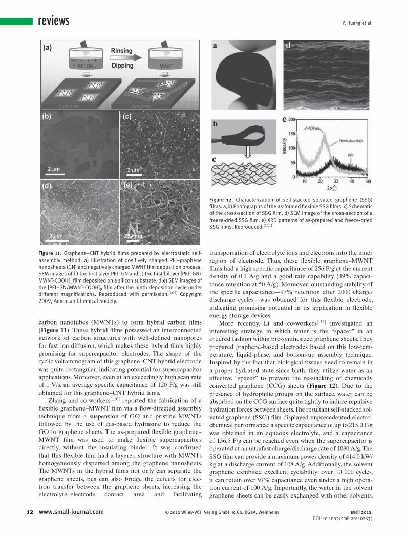
Figure 11 . Graphene–CNT hybrid fi lms prepared by electrostatic self-assembly method. a) Illustration of positively charged PEI–graphene nanosheets (GN) and negatively charged MWNT fi lm deposition process. SEM images of b) the fi rst layer PEI–GN and c) the fi rst bilayer [PEI–GN/MWNT-COOH] 1 fi lm deposited on a silicon substrate. d,e) SEM images of the [PEI–GN/MWNT-COOH] 9 fi lm after the ninth deposition cycle under different magnifi cations. Reproduced with permission. [ 109 ] Copyright 2009, American Chemical Society.
Figure 12 . Characterization of self-stacked solvated graphene (SSG) fi lms. a,b) Photographs of the as-formed fl exible SSG fi lms. c) Schematic of the cross-section of SSG fi lm. d) SEM image of the cross-section of a freeze-dried SSG fi lm. e) XRD patterns of as-prepared and freeze-dried SSG fi lms. Reproduced. [ 111 ]
carbon nanotubes (MWNTs) to form hybrid carbon fi lms
( Figure 11 ). These hybrid fi lms possessed an interconnected
network of carbon structures with well-defi ned nanopores
for fast ion diffusion, which makes these hybrid fi lms highly
promising for supercapacitor electrodes. The shape of the
cyclic voltammogram of this graphene–CNT hybrid electrode
was quite rectangular, indicating potential for supercapacitor
applications. Moreover, even at an exceedingly high scan rate
of 1 V/s, an average specifi c capacitance of 120 F/g was still
obtained for this graphene–CNT hybrid fi lms.
Zhang and co-workers [ 110 ] reported the fabrication of a
fl exible graphene–MWNT fi lm via a fl ow-directed assembly
technique from a suspension of GO and pristine MWNTs
followed by the use of gas-based hydrazine to reduce the
GO to graphene sheets. The as-prepared fl exible graphene–
MWNT fi lm was used to make fl exible supercapacitors
directly, without the insulating binder. It was confi rmed
that this fl exible fi lm had a layered structure with MWNTs
homogeneously dispersed among the graphene nanosheets.
The MWNTs in the hybrid fi lms not only can separate the
graphene sheets, bus can also bridge the defects for elec-
tron transfer between the graphene sheets, increasing the
electrolyte–electrode contact area and facilitating
12 www.small-journal.com © 2012 Wiley-VCH V
transportation of electrolyte ions and electrons into the inner
region of electrode. Thus, these fl exible graphene–MWNT
fi lms had a high specifi c capacitance of 256 F/g at the current
density of 0.1 A/g and a good rate capability (49% capaci-
tance retention at 50 A/g). Moreover, outstanding stability of
the specifi c capacitance—97% retention after 2000 charge/
discharge cycles—was obtained for this fl exible electrode,
indicating promising potential in its application in fl exible
energy storage devices.
More recently, Li and co-workers [ 111 ] investigated an
interesting strategy, in which water is the “spacer” in an
ordered fashion within pre-synthesized graphene sheets. They
prepared graphene-based electrodes based on this low-tem-
perature, liquid-phase, and bottom-up assembly technique.
Inspired by the fact that biological tissues need to remain in
a proper hydrated state since birth, they utilize water as an
effective “spacer” to prevent the re-stacking of chemically
converted graphene (CCG) sheets ( Figure 12 ). Due to the
presence of hydrophilic groups on the surface, water can be
absorbed on the CCG surface quite tightly to induce repulsive
hydration forces between sheets. The resultant self-stacked sol-
vated graphene (SSG) fi lm displayed unprecedented electro-
chemical performance: a specifi c capacitance of up to 215.0 F/g
was obtained in an aqueous electrolyte, and a capacitance
of 156.5 F/g can be reached even when the supercapacitor is
operated at an ultrafast charge/discharge rate of 1080 A/g. The
SSG fi lm can provide a maximum power density of 414.0 kW/
kg at a discharge current of 108 A/g. Additionally, the solvent
graphene exhibited excellent cyclability: over 10 000 cycles,
it can retain over 97% capacitance even under a high opera-
tion current of 100 A/g. Importantly, the water in the solvent
graphene sheets can be easily exchanged with other solvents,
erlag GmbH & Co. KGaA, Weinheim small 2012, DOI: 10.1002/smll.201102635
Applications of Graphene-Based Materials in Supercapacitors
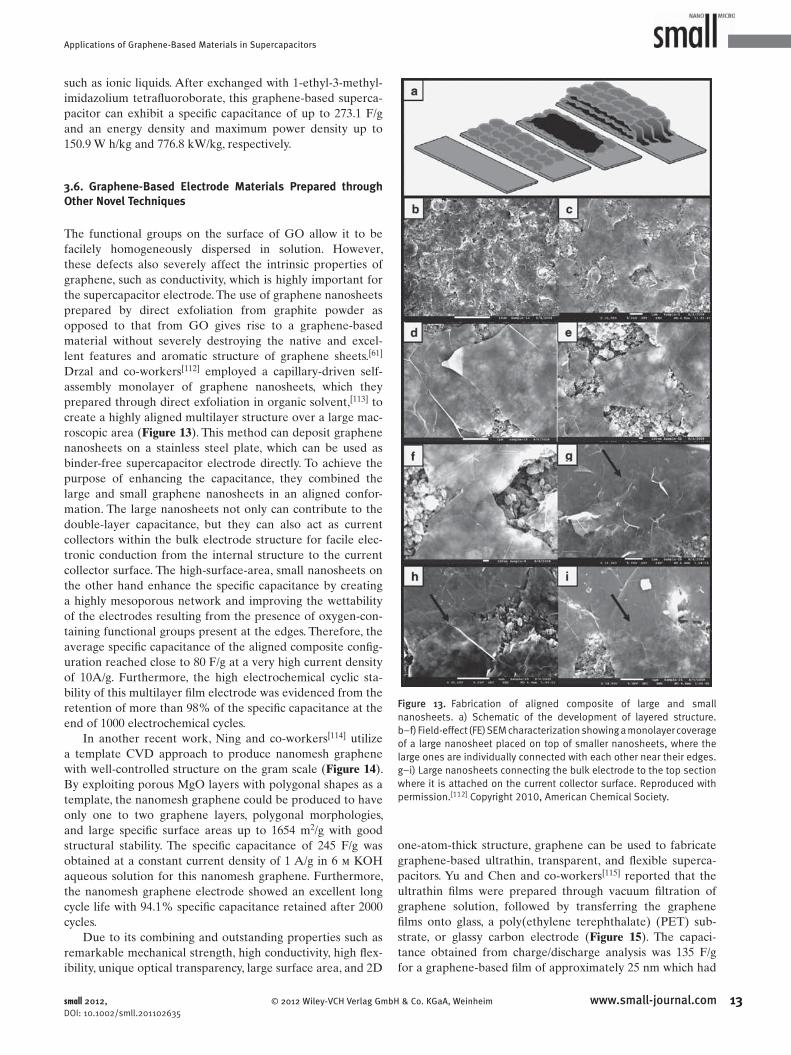
Figure 13 . Fabrication of aligned composite of large and small nanosheets. a) Schematic of the development of layered structure. b–f) Field-effect (FE) SEM characterization showing a monolayer coverage of a large nanosheet placed on top of smaller nanosheets, where the large ones are individually connected with each other near their edges. g–i) Large nanosheets connecting the bulk electrode to the top section where it is attached on the current collector surface. Reproduced with permission. [ 112 ] Copyright 2010, American Chemical Society.
such as ionic liquids. After exchanged with 1-ethyl-3-methyl-
imidazolium tetrafl uoroborate, this graphene-based superca-
pacitor can exhibit a specifi c capacitance of up to 273.1 F/g
and an energy density and maximum power density up to
150.9 W h/kg and 776.8 kW/kg, respectively.
3.6. Graphene-Based Electrode Materials Prepared through Other Novel Techniques
The functional groups on the surface of GO allow it to be
facilely homogeneously dispersed in solution. However,
these defects also severely affect the intrinsic properties of
graphene, such as conductivity, which is highly important for
the supercapacitor electrode. The use of graphene nanosheets
prepared by direct exfoliation from graphite powder as
opposed to that from GO gives rise to a graphene-based
material without severely destroying the native and excel-
lent features and aromatic structure of graphene sheets. [ 61 ]
Drzal and co-workers [ 112 ] employed a capillary-driven self-
assembly monolayer of graphene nanosheets, which they
prepared through direct exfoliation in organic solvent, [ 113 ] to
create a highly aligned multilayer structure over a large mac-
roscopic area ( Figure 13 ). This method can deposit graphene
nanosheets on a stainless steel plate, which can be used as
binder-free supercapacitor electrode directly. To achieve the
purpose of enhancing the capacitance, they combined the
large and small graphene nanosheets in an aligned confor-
mation. The large nanosheets not only can contribute to the
double-layer capacitance, but they can also act as current
collectors within the bulk electrode structure for facile elec-
tronic conduction from the internal structure to the current
collector surface. The high-surface-area, small nanosheets on
the other hand enhance the specifi c capacitance by creating
a highly mesoporous network and improving the wettability
of the electrodes resulting from the presence of oxygen-con-
taining functional groups present at the edges. Therefore, the
average specifi c capacitance of the aligned composite confi g-
uration reached close to 80 F/g at a very high current density
of 10A/g. Furthermore, the high electrochemical cyclic sta-
bility of this multilayer fi lm electrode was evidenced from the
retention of more than 98% of the specifi c capacitance at the
end of 1000 electrochemical cycles.
In another recent work, Ning and co-workers [ 114 ] utilize
a template CVD approach to produce nanomesh graphene
with well-controlled structure on the gram scale ( Figure 14 ).
By exploiting porous MgO layers with polygonal shapes as a
template, the nanomesh graphene could be produced to have
only one to two graphene layers, polygonal morphologies,
and large specifi c surface areas up to 1654 m 2 /g with good
structural stability. The specifi c capacitance of 245 F/g was
obtained at a constant current density of 1 A/g in 6 m KOH
aqueous solution for this nanomesh graphene. Furthermore,
the nanomesh graphene electrode showed an excellent long
cycle life with 94.1% specifi c capacitance retained after 2000
cycles.
Due to its combining and outstanding properties such as
remarkable mechanical strength, high conductivity, high fl ex-
ibility, unique optical transparency, large surface area, and 2D
© 2012 Wiley-VCH Verlag Gmbsmall 2012, DOI: 10.1002/smll.201102635
one-atom-thick structure, graphene can be used to fabricate
graphene-based ultrathin, transparent, and fl exible superca-
pacitors. Yu and Chen and co-workers [ 115 ] reported that the
ultrathin fi lms were prepared through vacuum fi ltration of
graphene solution, followed by transferring the graphene
fi lms onto glass, a poly(ethylene terephthalate) (PET) sub-
strate, or glassy carbon electrode ( Figure 15 ). The capaci-
tance obtained from charge/discharge analysis was 135 F/g
for a graphene-based fi lm of approximately 25 nm which had
13www.small-journal.comH & Co. KGaA, Weinheim

Y. Huang et al.reviews
1
Figure 14 . Illustration of the formation of the polygonal nanomesh graphene. Reproduced with permission. [ 114 ] Copyright 2011, Royal Society of Chemistry.
a transmittance of 70% at 550 nm and a high power density
of 7200 W/kg in 2 m KCl electrolyte. It is suggested that the
light-weight architecture effi ciently employs graphene mate-
rials to facilitate a minimal diffusion length for electrolyte
ions to access the active material while improving the charge
transport kinetics resulting in a high energy and power den-
sity electric double-layer capacitor.
Furthermore, it has been studied that inkjet printing
is a useful approach to prepare graphene thin-fi lm-based
electronic devices. Accordingly, Lee and co-workers [ 116 ]
reported for the fi rst time the feasibility of inkjet-printing
a GO aqueous solution directly on Ti foils and then subse-
quently using thermal reduction as a new avenue for fabri-
cating graphene-thin-fi lm-based supercapacitor electrodes.
The specifi c capacitance of these electrodes decreased from
125 to 121 F/g over 1000 CV cycles at a constant scan rate
of 50 mV/s demonstrating 96.8% capacitance retention. In
another interesting work, Ajayan and co-workers [ 117 ] demon-
strated the utilization of pristine and multilayer graphene as
electrodes in a novel “in-plane” device geometry for use in
supercapacitors, as depicted in Figure 16 . Compared to the
4 www.small-journal.com © 2012 Wiley-VCH Verlag GmbH & Co. KGaA,
Figure 15 . Ultrathin fi lms prepared by fi ltration of graphene solution. a) Photographs of transparent thin fi lms of varying thickness on glass slides. b) TEM image of graphene collected from dispersion before fi ltration. c) SEM image of graphene fi lm on glass slide. Reproduced with permission. [ 115 ] Copyright 2010, American Institute of Physics.
Figure 16 . a) Schemafabrication of supercoperating principle infor the performance ewith permission. [ 117 ]
conventional stacked geometry, it is con-
sidered that this favorable in-plane design
offers three opportunities to improve
the performance of this graphene-based
supercapacitor: 1) the electrolyte ions may
enhance the interaction with all the carbon
layers (Figure 16 a), leading to a full utili-
zation of the high surface area offered by
the graphene layers; 2) the graphene-based
2D architecture also allows for employing
the unique electrochemical properties of
graphene edges along with the basal planes
of graphene; 3) this 2D in-plane design
allowed the possibility of extreme mini-
aturization of device thickness (e.g., single-layer graphene
devices). As a result, the best capacitance value of this novel
graphene-based 2D “in-plane” supercapacitors was up to
250 F/g, and the normalized capacitance reached 394 μ F/cm 2 ,
higher than the previously reported 300 μ F/cm 2 . [ 118 ]
3.7. The Effect of the Electrolyte
A main issue with the carbon-based supercapacitor elec-
trode materials is that the entire surface area is not elec-
trochemically accessible by an electrolyte. This has been
attributed to the following facts: i) a small micropore size
(pore size < 2 nm) in porous carbon results in the low rate
of molecular or ionic transport through the pores, and
ii) a hydrophobic graphite-like surface provides low coverage
that is accessible for the formation of a double layer. [ 119 , 120 ]
Weinheim
tic depiction of the stacked geometry used for the apacitor devices. b) Schematic depiction of the case of the in-plane supercapacitor device utilized valuation of graphene as electrodes. Reproduced
Copyright 2011, American Chemical Society.
small 2012, DOI: 10.1002/smll.201102635

Applications of Graphene-Based Materials in Supercapacitors
Figure 17 . Poly(ionic liquid)-modifi ed reduced graphene oxide (PIL:RGO) electrode materials. a) Optical images of graphene oxide (GO) in propylene carbonate (PC) and PIL:RGO in PC. b) SEM and c) TEM image of PIL:RGO platelets. d) Schematic diagram of the supercapacitor based on the PIL:RGO electrodes and ionic liquid electrolyte (EMIM-NTf 2 ). Reproduced with permission. [ 123 ] Copyright 2011, American Chemical Society.
These drawbacks also restrict the appli-
cations of graphene-based materials as
electrodes in supercapacitors. Hsieh and
co-workers [ 121 ] thus studied the surface
accessibility of GO sheets using different
electrolytes, such as Li 2 SO 4 and Na 2 SO 4 .
This work adopted a fi ltration technique
to prepare GO stacking layers with a high
oxidation level on carbon paper forming
a fl exible electrode for supercapacitors.
The GO sheets were still occupied by
oxygen-containing groups and gener-
ated highly oxidized basal planes and
edges. It is interesting to fi nd that GO-
based capacitors displays specifi c capaci-
tances of 238.0 and 98.8 F/g in Li 2 SO 4
and Na 2 SO 4 electrolytes, respectively.
The difference of diffusivities in GO
sheets between the Li + and Na + ion have
been considered to be the reason for
this difference in the capacitance results.
Because 1) Li + is smaller than Na + and
2) the hydrated Li + ion forms dual layers,
whereas the hydrated Na + ion possibly
prefers monolayer adsorption on the GO
sheets, the diffusion coeffi cient of Li + is three times higher
than that of Na + in the GO-based supercapacitors. Accord-
ingly, this work has shed some light on how electrolyte
type affects the electrochemical performance of GO-based
supercapacitors, favoring the fundamental properties of
capacitive behavior on graphene-based materials.
Additionally, supercapacitors can be coupled with fuel
cells or batteries to deliver the high power needed during
acceleration and to recover the energy during braking.
However, a major shortcoming of current supercapacitors
is their low energy density (typically 5–10 W h/kg), which is
signifi cantly lower than the 20–35 W h/kg of lead-acid, the
40–100 W h/kg of Ni metal hydride, and the 120–170 W h/kg
of lithium-ion. [ 122 ]
Owing to the limited potential of 1 V in aqueous solution,
employing other nonaqueous electrolytes to overcome this
narrow electrochemical window is a key issue in the devel-
opment of high-performance supercapacitors. Conventional
organic electrolytes, such as tetraethylammonium tetrafl uor-
oborate and triethylmethylammonium tetrafl uoroborate in
acetonitrile, have been applied to fabricate supercapacitors
with a relatively wide potential window. [ 71 ] Nevertheless,
organic electrolytes suffer from the drawbacks involving
electrolyte depletion upon charge, narrow operational tem-
perature range, and low safety. Therefore, ionic liquids have
been used to replace organic electrolytes in a wide range of
applications. Their winning properties, including high ionic
conductivity, wider electrochemical window (up to 7 V),
excellent thermal stability (–40 to + 200 ° C typical), nonvola-
tility, nonfl ammability, and nontoxicity, make them excellent
electrolytes for various electrochemical systems. [ 122 ] Rao
and co-workers [ 35 ] were the fi rst to use an ionic liquid with
graphene-based materials, which were prepared by high-
temperature exfoliation, to fabricate supercapacitors. However,
© 2012 Wiley-VCH Verlag Gmbsmall 2012, DOI: 10.1002/smll.201102635
due to the relatively low obtained specifi c capacitance
(75 F/g), an energy density of only 31.9 W h/kg at 5 mV/s
and 60 ° C was gained. To further improve the compatibility
between graphene-based materials and ionic liquid elec-
trolytes, Suh and co-workers [ 123 ] incorporated a poly(ionic
liquid)-modifi ed reduced graphene oxide (PIL:RGO) elec-
trode and an ionic liquid (IL) electrolyte (specifi cally, 1-
ethyl-3-methylimidazolium bis(trifl uoromethylsulfonyl)amide
or EMIM-NTf 2 ) to develop a high-performance supercapac-
itors ( Figure 17 ). These PIL-modifi ed reduced GO materials
offer advantages for supercapacitor applications in that they
could provide enhanced compatibility with certain IL electro-
lytes and improve the accessibility of IL electrolyte ions into
the graphene electrodes. As a result, a supercapacitor assem-
bled with such a PIL:RGO electrode and with EMIM-NTf 2
as the electrolyte exhibited a specifi c capacitance of 187 F/g.
Nevertheless, the energy density is still low, and a maximum
energy density of only 6.5 W h/kg with a maximum power
density of 2.4 kW/kg was also obtained.
Recently, Jang and co-workers [ 122 ] reported results of
a study on a mesoporous graphene structure that is acces-
sible for ionic liquid electrolytes and, thus reaches an
exceptionally high EDL capacitance and an unprecedented
high level of energy density even though ionic liquids have
large molecules and high viscosity. They prepared curved
graphene sheets by injecting a GO aqueous solution into a
forced conventional oven in which a stream of compressed
air was introduced to produce a fl uidized-bed situation.
Upon removal of the solvent or liquid, the desired curved
graphene sheets were obtained. This curved graphene sheet
morphology ( Figure 18 ) is capable of preventing graphene
sheets from closely re-stacking with one another when they
are packed or compressed into an electrode structure, which
results in maintaining a mesoporous structure with pore
15www.small-journal.comH & Co. KGaA, Weinheim

Y. Huang et al.reviews
1
Figure 18 . Morphology of curved graphene sheet. a) SEM image of curved graphene sheets, b) TEM image of fl at graphene sheets prepared by a conventional chemical route (scale bar 500 nm). Reproduced with permission. [ 122 ] Copyright 2010, American Chemical Society.
sizes in the range of 2 to 25 nm. The specifi c capacitances
of curved graphene-based supercapacitors in an ionic liquid
are typically 100–250 F/g at a high current density of 1 A/g
with a discharge voltage of 4.0 V. Furthermore, the shape of
the cyclic voltammogram is nearly rectangular, indicating the
ideal double-layer capacitor behavior and no major pseudo-
capacitance contribution. Importantly, the ionic liquid,
EMIM BF 4 , can work at a voltage of up to 4.5 V, leading to
an excellent energy density of 85.6 W h/kg at 1 A/g at room
temperature (or 136 W h/kg at 80 ° C), which is comparable
to that of a modern nickel metal hydride battery used in a
hybrid vehicle. [ 122 ] This breakthrough energy storage device
is possible attributed to the high intrinsic capacitance and the
exceptionally high specifi c surface area of curved graphene
6 www.small-journal.com © 2012 Wiley-VCH V
sheets that can be readily accessed and wetted by an ionic
liquid electrolyte capable of operating at a high voltage.
4. Graphene-Conducting Polymer-Composite-Based Pseudo-capacitors
4.1. Electrode Materials Based on (Graphene Oxide)–PANI Composites
Conductive polymers (CPs) have been widely studied in
supercapacitors due to their very high pseudo-capacitance.
Accordingly, the main conductive polymer materials that
have been investigated for the supercapacitor electrode are
polyaniline (PANI), [ 124 ] polypyrrole (PPY), [ 125 ] polythiophene
(PTH), and their derivatives. [ 126 ] Among these polymers,
PANI is considered the most promising material because of
its high capacitive characteristics, low cost, and ease of prepa-
ration. [ 127 , 128 ] Nevertheless, the relatively poor cycling life and
stability severely restrict its practical applications. [ 129 ] In con-
trast, carbon-based materials, such as activated carbon (AC),
mesoporous carbon (MC), and carbon nanotubes (CNTs)
usually exhibit good stability, but the capacitance values are
relatively low due to the limited active surface in the mate-
rials. [ 40 , 130 , 131 ] Consequently, composite materials comprising
carbon-based materials such as CNTs and conducting poly-
mers such as PANIs have been investigated as supercapacitor
electrodes, and high capacitances and improved stability have
been achieved [ 132 , 133 ] due to the synergetic combination of
the excellent conducting and mechanical properties of CNTs
and the high pseudo-capacitance of the PANIs. However, the
high cost as well as relatively low electric double-layer capac-
itance (only up to 80 F/g) restricts the practical application
of pristine CNTs. [ 44 , 134 ] Graphene has thus been applied for
preparing composites with CPs to be used as supercapacitor
electrodes, owing to its many excellent and unique features.
Hao and co-workers [ 135 ] reported a novel kind of elec-
trode material based on fi brillar PANI doped with graphene
oxide sheets, which was synthesized via in situ polymerization
of the monomer in the presence of graphene oxide. Its spe-
cifi c capacitance was up to 531 F/g, which is much higher than
pure PANI, indicating the synergistic effect between GO and
PANI. In another work of Hao’s group, [ 129 ] they further inves-
tigated the effect of raw graphite material sizes and feeding
ratios on the electrochemical properties of the GO–PANI
composites. They found that the morphology of the
prepared composites is infl uenced dramatically by the dif-
ferent mass ratios. These composites are proposed to be com-
bined through a) an electrostatic interaction (doping process),
b) hydrogen bonding, and c) π – π stacking interactions. The
highest specifi c capacitances of 746 F/g (12 500 mesh of
pristine graphite powder) and 627 F/g (500 mesh of pristine
graphite powder) corresponding to the mass ratios of1:200
and 1:50 (graphene oxide/aniline), respectively, are obtained,
compared to that of PANI (216 F/g) at a current density of
200 mA/g between 0.0 and 0.4 V. Moreover, the improved
capacitance retention of 73% (12 500 mesh) and 64% (500
mesh) after 500 cycles is obtained for the mass ratios of 1:23
erlag GmbH & Co. KGaA, Weinheim small 2012, DOI: 10.1002/smll.201102635

Applications of Graphene-Based Materials in Supercapacitors
Figure 19 . Schematic illustration of nucleation and growth mechanism of PANI nanowires: a) heterogeneous nucleation on GO nanosheets, b) homogeneous nucleation in bulk solution. Reproduced with permission. [ 136 ] Copyright 2010, American Chemical Society.
and 1:19, respectively (PANI, 20%). The enhanced specifi c
capacitance and cycling life implies a good synergistic effect
between two components.
In another corresponding work, Wei and Han and col-
leagues [ 136 ] investigated a facile method to prepare PANI
nanowire arrays vertically aligned on graphene oxide
nanosheets as shown in Figure 19 and 20 . This hierarchical
© 2012 Wiley-VCH Verlag GmbH
Figure 20 . SEM images of PANI–GO samples obtained at different reaction intervals: a) 2.5 h, b) 3 h, c) 8 h, and d) 24 h. Reproduced with permission. [ 136 ] Copyright 2010, American Chemical Society.
small 2012, DOI: 10.1002/smll.201102635
nanocomposite of PANI nanowire arrays on GO sheets
displayed a synergistic effect used as the supercapacitor
electrode materials. Not only specifi c capacitance of the
nanocomposite, but also the cycle life of this composite
showed better performance than those of the randomly con-
nected PANI nanowires. The specifi c capacitance of hier-
archical PANI–GO was 555 F/g at a discharge current of
0.2 A/g and was still kept as high as 227 F/g even at a dis-
charge current density of 2 A/g. More importantly, after
2000 consecutive cycles, the capacitance retention of hierar-
chical PANI–GO nanocomposite was maintained at 92% of
its initial capacitance, while pristine PANI kept only 74% of
its initial capacitance. In general, conducting polymers such
as PANI often suffer from a limited long-term stability during
cycling because the swelling and shrinking of the polymers
may lead to degradation. Thus, the better stability of hier-
archical PANI–GO is attributed to the synergistic effect of
GO nanosheets and PANI nanowire arrays. GO nanosheets
that have unique structural and mechanical properties may
restrict the mechanical deformation of PANI nanowires in
the redox process, which avoided destroying the electrode
material and was benefi ted to a better stability. Additionally,
the vertical nanowire arrays were able to strain relaxation,
which made them decrease the breaking during the doping/
dedoping process of counterions. [ 137 , 138 ]
4.2. Electrodes Based on (Reduced Graphene)–PANI Composites
Due to the electrochemical instability of GO, GO–PANI com-
posites cannot take advantage of the best potentials of GO,
which would be ideal for applications in supercapacitor elec-
trodes; only a small amount of insulating GO has been used
in such composites because excess GO would reduce the con-
ductivity of the composite. [ 134 , 135 ] Thus, graphene nanosheets
(GNS) are more favorable than GO to be doped into PANI
composites. Zhao and co-workers [ 134 ] fabricated graphene
and PANI nanofi ber composites through an in situ polymeri-
zation of aniline monomer in the presence of graphene oxide
under acidic conditions, which was then followed by the
reduction of GO to graphene using hydrazine. Reoxidation
and reprotonation of the reduced PANI followed to give the
graphene–PANI nanocomposites. They found that the com-
posites that contained 80 wt% of GO showed the highest spe-
cifi c capacitance of 480 F/g at a current density of 0.1 A/g. In
addition, when the current density is increased up to 0.5 A/g
and even 1 A/g, the specifi c capacitances still remain at a
high level above 200 F/g without a signifi cant decrease upon
charge/discharge cycling. While the BET surface areas of
all the composites is rather low, i.e., 4.3–20.2 m 2 /g, the much
higher specifi c capacitance of this graphene–PANI composite
compared with that of pure reduced graphene should be
mainly ascribed to the pseudo-capacitance from the PANI
nanofi bers in the composite. Furthermore, over 70% of the
original capacitance was retained after over 1000 cycles, indi-
cating that this electrode material has good cycling stability.
This stability is mainly due to the small amount of PANI in
the composites.
17www.small-journal.com & Co. KGaA, Weinheim

Y. Huang et al.reviews
1
Figure 21 . Scheme illustrating the preparation process of the hybrid materials reported by Wang and co-workers. Reproduced with permission. [ 139 ] Copyright 2010, Royal Society of Chemistry. In the image, GEO and APS refer to GO and ammonium persulfate, respectively; GEOP-1 represents the composite of GO and APS; GEP-2 represents the product obtained from reducing GEOP-1 and dedoping PANI simultaneously with14.4 mL of 8 M sodium hydroxide at 90 ° C for 5 h. GEP-3 represents the product obtained from immersing GEP-2 in 0.2 M HCl for redoping of PANI.
Figure 22 . Graphene–PANI composite paper as a fl exible electrode. Digital camera images of two freestanding graphene–PANI composite papers (left) and a curved graphene–PANI composite paper (right). Reproduced with permission. [ 146 ] Copyright 2009, American Chemical Society.
Although the cycling stability of the graphene–PANI com-
posite in the above work is good, their capacitance is still not
so satisfying. Thus, Wang and co-workers [ 139 ] presented for
the fi rst time a simple three-step synthesis method to prepare
a graphene–PANI composite as a supercapacitor electrode.
As shown in Figure 21 , this approach was realized by an in
situ polymerization/reduction–dedoping/redoping process. It
was observed that the reduced graphene sheets are covered
by nanostructured PANI granules completely and success-
fully. They pointed out that this perfect coverage of PANI on
graphene fully takes advantage of the large specifi c area of
graphene and could be favorable for the enhancement of the
electrochemical properties of the composite materials. The
composite material showed better electrochemical perform-
ance than both the pure individual components. A high spe-
cifi c capacitance of 1126 F/g was obtained with a retention
life of 84% after 1000 cycles for supercapacitors. Such a high
retention life for this graphene–PANI composite is mainly
due to the change from graphene oxide to graphene in the
hybrid material, leading to the improvement of mechanical
properties of the composite. In other words, the swelling
and shrinkage of PANI during the doping–dedoping proc-
esses can be restrained effi ciently. Furthermore, the energy
density and power density were 34.8 W h/kg and 136 kW/kg,
respectively, which were also better than those of the pure
component materials. In another report, using graphene-
nanosheet support materials to provide active sites for the
nucleation of PANI and for excellent electron transfer, Wei
and co-workers [ 140 ] synthesized a graphene–PANI composite
by in situ polymerization. In this case, graphene sheets not
only serve as a highly conductive support material, but they
also provide a large surface for the well-dispersed deposition
8 www.small-journal.com © 2012 Wiley-VCH V
of nanoscale PANI particles, resulting in an excellent syner-
gistic effect of graphene and PANI. As a result, the maximum
specifi c capacitance of 1046 F/g is obtained at a scan rate of
1 mV/s for GNS–PANI composite compared to 183 and 115
F/g for GNS and pure PANI, respectively.
Furthermore, it has been confi rmed that exfoliated GO
precursor can be electrochemically reduced to graphene at
cathodic potentials; in the meantime, the aniline monomer
can be polymerized at anodic potentials. [ 141 ] Accordingly,
Huang and Ma [ 142 ] developed a new one-step electrochemical
synthesis of graphene–PANI composite fi lms in large scale
using GO and aniline as the starting materials. Ten cycles of
potential scanning at a scan rate of 50 mV/s were used to syn-
thesize the graphene–PANI composite fi lms on an indium tin
oxide (ITO) electrode directly with high quality. The specifi c
capacitance value of the fabricated supercapacitor was 640
F/g, and it can maintain its 90% capacitance of the original
value after 1000 charge/discharge cycles, indicating good
cycling stability. It is suggested that the high specifi c capaci-
tance and good cycling stability of the supercapacitor might
be attributed to the perfect coverage structure of the layered
graphene–PANI composite fi lm, the large specifi c area, and
high conductivity.
4.3. Flexible Supercapacitors Prepared from Flexible Graphene–PANI Composite Films
Flexible supercapacitors have many potential applications
in various portable electronic devices. [ 143–145 ] A freestanding
binder-free electrode with favorable mechanical strength and
large capacitance is a vital component of a fl exible superca-
pacitor. [ 146 ] Free-standing and paper-like graphene-based
materials have displayed excellent fl exibility, outstanding
mechanical strength, and exceptional electrical conductivity,
and hence make them potentially suitable for fl exible elec-
trochemically active materials, including fl exible superca-
pacitors. [ 147 ] Cheng and co-workers [ 146 ] aimed to prepare
graphene–PANI composite paper ( Figure 22 ) as a fl exible
electrode, by combining the advantages of graphene paper
(high conductivity, mechanical strength, and fl exibility) and
of the PANI conducting polymer (large capacitance). This
erlag GmbH & Co. KGaA, Weinheim small 2012, DOI: 10.1002/smll.201102635

Applications of Graphene-Based Materials in Supercapacitors
Figure 23 . Proposed pathway of the synthesis of graphene–PPy nanocomposites. PSS represents poly(styrene sulfonate). Reproduced with permission. [ 150 ] Copyright 2011, IOP Publishing Ltd.
fl exible graphene–PANI composite paper
was prepared by in situ anodic electropo-
lymerization of aniline monomers into a
PANI fi lm on graphene paper. This fl ex-
ible graphene–PANI composite electrode
exhibited important features, such as i)
improved electrical conductivity in PANI
due to the presence of the graphene
paper, ii) homogeneous ion accessibility
and high interfacial charge uptake inside
the layered structure of the graphene–
PANI paper, and iii) a triple supercapac-
itive storage mechanism (electric double
layer charging/discharging and pseudo-
capacitive redox reactions of oxygen-
containing functional groups of graphene
sheet layers and pseudo-capacitive redox
reactions of PANI layers). Based on these,
this fl exible graphene–PANI electrode
showed a favorable tensile strength of
12.6 MPa and a stable large electrochem-
ical capacitance of 233 F/g and 135 F/cm 3
for gravimetric and volumetric capaci-
tances, respectively. In another work, Yan
and co-workers [ 147 ] reported a low-cost
technique via simple rapid-mixture polymerization of aniline
using graphene papers as substrates to fabricate free-standing,
fl exible graphene–PANI hybrid papers. Compared to tradi-
tional chemical polymerization and electro-polymerization,
this rapid-mixture polymerization approach has two advan-
tages: 1) this process is quite simple, and large-area deposi-
tion can be realized without the need of costly apparatus and
the assistance of heating or cooling, and 2) secondary growth
of PANI is limited, resulting in ultrathin PANI coatings with
high specifi c surface area, which were unlikely to destroy the
fl exibility of the pristine graphene papers. The measured spe-
cifi c capacitance of the graphene–PANI electrode reached
as high as 489 F/g. Importantly, after 500 cycles there is still
more than 475 F/g remaining at 400 mA/g (above 96% of
the original value), illustrating this electrode possesses good
cycling stability and lifetime. Therefore, this graphene–PANI
hybrid paper is considered to have potential applications in
fl exible supercapacitors.
4.4. Electrode Materials Based on Other Graphene–(Conducting Polymer) Composites
Polypyrrole (PPy) has also been used as the conducting
polymer for supercapacitor electrodes, owing to its high elec-
trical conduction accompanied by a high stability when exposed
to ambient conditions, its ease of synthesis, and its cost -ffec-
tiveness. [ 148 , 149 ] Lee and co-workers [ 150 ] established a unique
nanoarchitecture involving PPy and graphene nanosheets
through in situ polymerization, as displayed in Figure 23 . In
this graphene–PPy composite, graphene nanosheets serve as
a support material for the electrochemical utilization of PPy
and also provides the path for electron transfer. The specifi c
capacitance value of the nanocomposite achieved 267 F/g at
© 2012 Wiley-VCH Verlag Gmbsmall 2012, DOI: 10.1002/smll.201102635
a scan rate of 100 mV/s compared to 137 mV/s for PPy. The
authors suggested that the improvement in electrochemical
performance of the graphene–PPy nanocomposite, as com-
pared to individual graphene and PPy, was probably due to
1) the oxidation or deoxidation of α - or β -C atoms in the
PPy rings, which was facilitated by the presence of graphene
nanosheets, 2) the attachment of PPy onto the surface of
graphene nanosheets playing a part in reducing diffusion and
migration length [ 151 ] and thus facilitating the electrochemical
utilization of PPy, and 3) the synergistic effect between PPy
and graphene nanosheets. [ 152 ] The energy density and power
density were calculated to be 94.93 W h/kg and 3797.2 W/kg,
respectively. Moreover, after 500 cycles, only a 10% decrease
in the specifi c capacitance was noted as compared to the ini-
tial value, indicating the improved electrochemical cyclic sta-
bility of the nanocomposite.
Zhao and co-workers [ 153 ] introduced the conception of
electrostatic interactions between negatively charged GO
sheets and positively charged surfactant micelles to prepare
layered graphene oxide nanostructures with sandwiched con-
ducting polymers as supercapacitor electrodes as shown in
Figure 24 . Two GO–(conducting polymer) composite samples
with fi brous and spherical morphologies of the PPy were pre-
pared for comparison. It was found that the morphology of
the conducting polymer played a very important role in the
electrochemical performance as presented in Table 1 .
A high specifi c capacitance of 510 F/g was obtained on
the GO–(fi brous PPy) composite, GO–PPy(F), and a high
capacitance retention ratio (about 70%) was observed when
the current density was increased by 17 times. The GO–
(spherical PPy) composite, GO–PPy(S), performed similarly
to that of GO–PPy(F) at low current density; however, when
the current density increased, GO–PPy(S) performed worse
than that of GO–PPy(F) Both the capacitance of GO–PPy(F)
19www.small-journal.comH & Co. KGaA, Weinheim

Y. Huang et al.reviews
20
Figure 24 . Schematic Illustration of the formation process of the GO–PPy composite. Reproduced with permission. [ 153 ] Copyright 2010, American Chemical Society.
Figure 25 . a) SEM image showing electropolymerized pyrrole on Ti; b) magnifi ed image of (a); c) electrophoretic deposition (EPD) of graphene on a Ti plate; d) magnifi ed cross-sectional image of graphene platelets; e) nucleation of polymerization on graphene platelets; f) electropolymerization of pyrrole on graphene platelets; g) Raman spectra of graphene. Reproduced with permission. [ 154 ] Copyright 2011, Royal Society of Chemistry.
and GO–PPy(S) were much better than that of pure PPy.
Moreover, over 70% of the original capacitance was retained
for the composite electrode GO–PPy(FS) after 1000 cycles,
while only 30% was retained for the pure PPy(F) electrode,
indicating a much better cycle ability of the composite mate-
rial than the pure polymer electrode. These attractive results
for graphene–PPY composite electrodes are due to 1) the
fact that the exfoliated GO sheets dispersed in solution pro-
vide a large accessible surface for the attachment of the con-
ducting polymer on both sides; 2) the 3D layered structure
enhancing the mechanical strength of the composite and
stabilizing the polymers during the charge/discharge process;
3) the GO nanostructure with conducting polymer pillars
effectively reducing the dynamic resistance of electrolyte
ions; and 4) the readily accessible conducting polymers con-
tributing pseudo-capacitance to the overall energy storage at
a signifi cant extent.
Recently, Subramanian, Nair, and co-workers [ 154 ] utilized
graphene nanolayers, which were synthesized using electro-
phoretic deposition of graphene, as a scaffold for PPy elec-
tropolymerization and created a composite electrode for
supercapacitor applications. As depicted in Figure 25 , the
composite electrode structure was highly porous compared
with that of the PPy electrode (Figure 25 a,b,e,f), and it was
believed that this porosity enhances the electrode inter-
action with the electrolyte. Moreover, PPy nucleated on
www.small-journal.com © 2012 Wiley-VCH V
Table 1. Specifi c gravimetric capacitance of various electrodes at dif-ferent current densities. GOR represents reduced GO in this table. Reproduced with permission. [ 153 ] Copyright 2010, American Chemical Society.
Samples 0.3 A/g 0.5 A/g 1 A/g 2 A/g 3 A/g 5 A/g
GOR 124 98 92
GO–PPy(F) 510 480 440 456 374 351
PPy(F) 360 250 175 150 120 130
GO–PPy(S) 528 483 364 307 276 255
graphene can utilize the extremely high specifi c surface area
of graphene, and this mode of polymerization is benefi cial
because it exposes maximum surface sites for Faradic redox
reactions of the supercapacitor electrode. As a result, these
graphene–PPy composite electrodes exhibited an ultrahigh
specifi c capacitance of 1510 F/g, an area capacitance of 151
mF/cm 2 , and a volume capacitance of 151 F/cm 3 at 10 mV/s.
5. Pseudo-capacitors Based on Graphene–(Metal Oxide) Composites
5.1. Electrode Materials Based on Graphene–MnO 2 Composites
MnO 2 is supposed to be a promising electrode material for appli-
cations in supercapacitors and has attracted much attention
erlag GmbH & Co. KGaA, Weinheim small 2012, DOI: 10.1002/smll.201102635
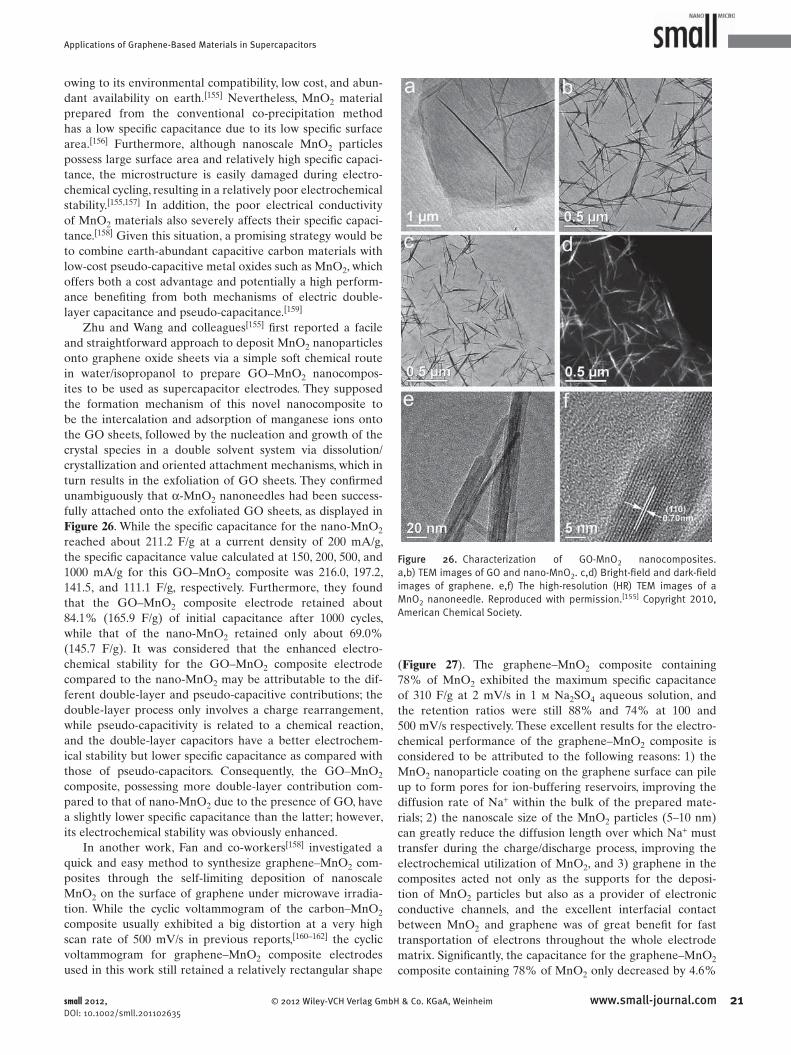
Applications of Graphene-Based Materials in Supercapacitors
Figure 26 . Characterization of GO-MnO 2 nanocomposites. a,b) TEM images of GO and nano-MnO 2 . c,d) Bright-fi eld and dark-fi eld images of graphene. e,f) The high-resolution (HR) TEM images of a MnO 2 nanoneedle. Reproduced with permission. [ 155 ] Copyright 2010, American Chemical Society.
owing to its environmental compatibility, low cost, and abun-
dant availability on earth. [ 155 ] Nevertheless, MnO 2 material
prepared from the conventional co-precipitation method
has a low specifi c capacitance due to its low specifi c surface
area. [ 156 ] Furthermore, although nanoscale MnO 2 particles
possess large surface area and relatively high specifi c capaci-
tance, the microstructure is easily damaged during electro-
chemical cycling, resulting in a relatively poor electrochemical
stability. [ 155 , 157 ] In addition, the poor electrical conductivity
of MnO 2 materials also severely affects their specifi c capaci-
tance. [ 158 ] Given this situation, a promising strategy would be
to combine earth-abundant capacitive carbon materials with
low-cost pseudo-capacitive metal oxides such as MnO 2 , which
offers both a cost advantage and potentially a high perform-
ance benefi ting from both mechanisms of electric double-
layer capacitance and pseudo-capacitance. [ 159 ]
Zhu and Wang and colleagues [ 155 ] fi rst reported a facile
and straightforward approach to deposit MnO 2 nanoparticles
onto graphene oxide sheets via a simple soft chemical route
in water/isopropanol to prepare GO–MnO 2 nanocompos-
ites to be used as supercapacitor electrodes. They supposed
the formation mechanism of this novel nanocomposite to
be the intercalation and adsorption of manganese ions onto
the GO sheets, followed by the nucleation and growth of the
crystal species in a double solvent system via dissolution/
crystallization and oriented attachment mechanisms, which in
turn results in the exfoliation of GO sheets. They confi rmed
unambiguously that α -MnO 2 nanoneedles had been success-
fully attached onto the exfoliated GO sheets, as displayed in
Figure 26 . While the specifi c capacitance for the nano-MnO 2
reached about 211.2 F/g at a current density of 200 mA/g,
the specifi c capacitance value calculated at 150, 200, 500, and
1000 mA/g for this GO–MnO 2 composite was 216.0, 197.2,
141.5, and 111.1 F/g, respectively. Furthermore, they found
that the GO–MnO 2 composite electrode retained about
84.1% (165.9 F/g) of initial capacitance after 1000 cycles,
while that of the nano-MnO 2 retained only about 69.0%
(145.7 F/g). It was considered that the enhanced electro-
chemical stability for the GO–MnO 2 composite electrode
compared to the nano-MnO 2 may be attributable to the dif-
ferent double-layer and pseudo-capacitive contributions; the
double-layer process only involves a charge rearrangement,
while pseudo-capacitivity is related to a chemical reaction,
and the double-layer capacitors have a better electrochem-
ical stability but lower specifi c capacitance as compared with
those of pseudo-capacitors. Consequently, the GO–MnO 2
composite, possessing more double-layer contribution com-
pared to that of nano-MnO 2 due to the presence of GO, have
a slightly lower specifi c capacitance than the latter; however,
its electrochemical stability was obviously enhanced.
In another work, Fan and co-workers [ 158 ] investigated a
quick and easy method to synthesize graphene–MnO 2 com-
posites through the self-limiting deposition of nanoscale
MnO 2 on the surface of graphene under microwave irradia-
tion. While the cyclic voltammogram of the carbon–MnO 2
composite usually exhibited a big distortion at a very high
scan rate of 500 mV/s in previous reports, [ 160–162 ] the cyclic
voltammogram for graphene–MnO 2 composite electrodes
used in this work still retained a relatively rectangular shape
© 2012 Wiley-VCH Verlag Gmbsmall 2012, DOI: 10.1002/smll.201102635
( Figure 27 ). The graphene–MnO 2 composite containing
78% of MnO 2 exhibited the maximum specifi c capacitance
of 310 F/g at 2 mV/s in 1 m Na 2 SO 4 aqueous solution, and
the retention ratios were still 88% and 74% at 100 and
500 mV/s respectively. These excellent results for the electro-
chemical performance of the graphene–MnO 2 composite is
considered to be attributed to the following reasons: 1) the
MnO 2 nanoparticle coating on the graphene surface can pile
up to form pores for ion-buffering reservoirs, improving the
diffusion rate of Na + within the bulk of the prepared mate-
rials; 2) the nanoscale size of the MnO 2 particles (5–10 nm)
can greatly reduce the diffusion length over which Na + must
transfer during the charge/discharge process, improving the
electrochemical utilization of MnO 2 , and 3) graphene in the
composites acted not only as the supports for the deposi-
tion of MnO 2 particles but also as a provider of electronic
conductive channels, and the excellent interfacial contact
between MnO 2 and graphene was of great benefi t for fast
transportation of electrons throughout the whole electrode
matrix. Signifi cantly, the capacitance for the graphene–MnO 2
composite containing 78% of MnO 2 only decreased by 4.6%
21www.small-journal.comH & Co. KGaA, Weinheim

Y. Huang et al.reviews
22
Figure 27 . Capacitive properties of graphene–MnO 2 composites. a) CV curves of graphene and graphene–MnO 2 composites at 10 mV/s. b,c) CV curves of graphene–78%MnO 2 composite at different scan rates of 2, 10, 20, 50, 100, 200, and 500 mV/s. d) Galvanostatic charge/discharge curves of graphene–78%MnO 2 composite at current densities of 10, 20, and 50 mA/cm 2 in 1 M Na 2 SO 4 solution. Reproduced with permission. [ 158 ] Copyright 2010, Elsevier Ltd.
of the initial capacitance after 15 000 cycles at a scan rate of
500 mV/s, indicating the excellent electrochemical stability of
such an electrode material.
Zhao and co-workers [ 163 ] also developed an intriguing
type of graphene–MnO 2 composite use in supercapacitor
electrodes. First, they obtained the functionalized graphene by
reducing graphene oxide with poly(diallyldimethylammonium
chloride) (PDDA), changing the surface charge of reduced
graphene oxide from negative to positive. Then, the
graphene–MnO 2 composite was prepared by dispersing
negatively charged MnO 2 nanosheets on the functionalized
reduced graphene sheets via an electrostatic co-precipitation
method. The specifi c capacitance of this composite can reach
188 and 130 F/g at a current density of 0.25 and 4 A/g, respec-
tively, which are much higher values than those of pure func-
tionalized reduced graphene and MnO 2 nanosheets. It was
thought that the enhancement in the specifi c capacitance of
the graphene–MnO 2 composite may be due to the contribu-
tion of both components. Anchoring of the MnO 2 nanosheets
on the functionalized reduced graphene sheets effectively
prevent the latter from agglomeration, thus facilitating ion
transport in the electrode material, and eventually improving
www.small-journal.com © 2012 Wiley-VCH V
the electric double-layer capacitance. The effective charge
transfer in the electrode played an import role in enhancing
the specifi c capacitance and rate capability. For composite
sample of functionalized reduced graphene and MnO 2 , the
face-to-face assembly between the MnO 2 nanosheets and the
functionalized reduced graphene sheets, which exhibit good
electrical conductivity, results in an intimate interaction of
both components, enhancing charge transfer between the
two components and leading to rapid redox reactions of the
MnO 2 sheets.
In addition to MnO 2 , Mn 3 O 4 was investigated for use
in supercapacitor electrode materials. [ 164 ] Wang and co-
workers [ 165 ] synthesized Mn 3 O 4 –graphene nanocomposites
by mixing a graphene suspension in ethylene glycol with
MnO 2 organosol, followed by subsequent ultrasonication
processing and heat treatment. While the pure graphene
nanosheets have a specifi c BET surface area of 93.7 m 2 /g, it
was measured that Mn 3 O 4 –graphene nanocomposites have
a BET area of 1327.3 m 2 /g with an increase of more than
14 times, clearly proving the Mn 3 O 4 nanoparticles can effec-
tively reduce the stacking of graphene nanosheets. As a result,
a high specifi c capacitance of 256 F/g has been achieved for
erlag GmbH & Co. KGaA, Weinheim small 2012, DOI: 10.1002/smll.201102635

Applications of Graphene-Based Materials in Supercapacitors
Figure 28 . The preparation of ROGSCs by combining a sol–gel method and low-temperature annealing. Reproduced. [ 169 ]
Figure 29 . Characterizations of the composite materials. a) SEM image of Ni(OH) 2 nanoplates grown on graphene. b) TEM image of Ni(OH) 2 nanoplates grown on Graphene. c) SEM image of Ni(OH) 2 nanoparticles grown on GO. d) TEM image of Ni(OH) 2 nanoparticles grown on GO. e) SEM image of Ni(OH) 2 hexagonal nanoplates grown in free solution (without graphene). f) SEM images of simple physical mixture of pre-synthesized free Ni(OH) 2 nanoplates and graphene. Reproduced with permission. [ 171 ] Copyright 2010, American Chemical Society.
Mn 3 O 4 –graphene nanocomposites, which is almost double
that of pure graphene nanosheets.
5.2. Electrode Materials Based on Composites of Graphene and Other Metal Oxides
Despite its high cost, RuO 2 shows great potential for devel-
oping supercapacitors with higher energy and power densities
than carbon-based EDLCs and polymer-based pseudo-capac-
itors due to its high capacitance, reversible charge/discharge
features, and good electrical conductivity. However, in order
to fully utilize the Faradaic and non-Faradaic processes for
large-capacity charge storage of RuO 2 -based electrode mate-
rials, carbon-based materials [ 166–168 ] are usually used to pre-
vent the RuO 2 from forming large agglomerates, which may
signifi cantly degrade their electrochemical performance as a
results of the incomplete reaction of RuO 2 during the elec-
trochemical redox process that starts from the surface of
RuO 2 particles and becomes slower as the reaction proceeds,
especially for agglomerated large particles. [ 169 , 170 ] Hence,
graphene is an excellent choice as the carbon-based substrate
materials due to its outstanding properties.
Cheng and co-workers [ 169 ] fi rst exploited graphene
nanosheets as the substrate material to prepare hydrous
ruthenium oxide (RuO 2 )–(graphene sheet) composites
(ROGSCs) with different loadings of Ru through sol–gel
and low-temperature annealing processes ( Figure 28 ). It was
found that while the as-prepared graphene nanosheets tend
to randomly distribut and re-stack, the RuO 2 nanoparticles
in the ROGSCs were highly dispersed on the surface of the
graphene nanosheets and served as spacers to prevent the
graphene sheets from re-stacking. As a result, ROGSCs with
38.3 wt% of Ru (281 m 2 /g) had a higher BET specifi c sur-
face area than that of pure graphene sheets (108 m 2 /g) and of
pure RuO 2 powder (3.0 m 2 /g). The ROGSCs with 38.3 wt%
of Ru exhibited a high specifi c capacitance of ∼ 570 F/g at
1 mV/s, enhanced rate capability, and high energy density
(20.1 W h/kg) at low operation rate (100 mA/g) or high
power density (10 000 W/kg) at a reasonable energy density
© 2012 Wiley-VCH Verlag Gmbsmall 2012, DOI: 10.1002/smll.201102635
(4.3 W h/kg). The total specifi c capacitance of ROGSCs was
higher than the sum of specifi c capacitances of pure graphene
sheets and pure RuO 2 in their relative ratios, indicating a pos-
itive synergistic effect of graphene sheets and RuO 2 on the
improvement of electrochemical performance. Most impor-
tantly, after 1000 cycles at a current density of 1 A/g, 97.9%
of the original capacitance was still retained for this ROGSC
electrode, which is much higher than the pure RuO 2 elec-
trodes ( ∼ 42.0%). They believed that this great improvement
in electrochemical capacitive performance of ROGSC elec-
trodes was possibly due to the unique particle–sheet struc-
ture—which allowed the full utilization of the advantages
of both graphene sheets and RuO 2 , the greatly decreased
interparticle resistance of the electron pathways, the reduced
diffusion path, and the facilitated ionic motion during the
charge-storage/delivery process.
Dai and co-workers [ 171 ] directly grew single-crystal-
line Ni(OH) 2 hexagonal nanoplates on lightly oxided,
electrical conducting substrates of graphene nanosheets
to prepare advanced electrochemical pseudo-capacitor
materials ( Figure 29 ). The electrodes that are based on
Ni(OH) 2 –graphene composites showed an intriguing specifi c
23www.small-journal.comH & Co. KGaA, Weinheim

Y. Huang et al.reviews
24
capacitance of ∼ 1335 F/g at a charge and discharge current
density of 2.8 A/g. Even at a current density up to 45.7 A/g,
this composite electrode still displayed electrochemical
characteristics as pseudo-capacitor materials with a specifi c
capacitance of ∼ 952 F/g. The energy density was estimated to
be ∼ 37 W h/kg at a power density of ∼ 10 kW/kg in a voltage
range of 0.55 V. They concluded that several properties of
the composites comprising single-crystalline Ni(OH) 2 hex-
agonal nanoplates and graphene nanosheets contributed
to this attractive results. 1) The Ni(OH) 2 nanoplates were
directly grown and anchored on the graphene sheets through
both covalent chemical bonding and van der Waals interac-
tions. This intimate binding afforded facile electron trans-
port between the highly insulating Ni(OH) 2 nanoplates and
the highly conducting graphene nanosheets, which was key
to both the high specifi c capacitance and rate capability of
the Ni(OH) 2 –graphene materials. With little “dead” volume,
most of the Ni(OH) 2 nanoplates in the macroscopic ensemble
were electrochemically active through the 3D conducting
network of graphene nanosheets. Rapid charge transport
from the nanoplates to the underlying graphene afforded fast
redox reactions at high scan rates and charge and discharge
currents. 2) Single-crystalline thin nanoplates showed more
favorable electrochemical characteristics over the less crys-
talline small nanoparticles. Importantly, there was no obvious
decrease of the specifi c capacitance observed after over 2000
cycles of charge/discharge cycling at a high current density of
28.6 A/g, demonstrating excellent cycling stability and long
cycle life.
In another work, among the transition metal oxides, Fe 3 O 4
is one of the most promising electrode materials due to its
low cost and low environmental impact. However, previous
work on Fe 3 O 4 as supercapacitor electrodes have shown low
capacitance values of 60–80 F/g, [ 172 ] which is mainly due to its
low electrical conductivity; electrical conductivity is needed
to enable effective ion diffusion. Yan and co-workers [ 173 ]
reported a facile technique to fabricate nanocomposites with
Fe 3 O 4 nanoparticles attached to reduced graphene oxide
sheets by a solvothermal process, which combines the growth
of Fe 3 O 4 nanoparticles and the reduction of graphene oxide
sheets in one single step. Then, they further prepared the
thin fi lm supercapacitor electrodes by spray-deposition of
the Fe 3 O 4 –(graphene oxide sheet) nanocomposites without
insulating binders. This nanocomposite electrode showed
much higher specifi c capacitance than that of either pure
reduced graphene or pure Fe 3 O 4 nanoparticles due to the
much improved electrical conductivity and surface area. The
Fe 3 O 4 –(graphene oxide) nanocomposites with 73.5% Fe 3 O 4
nanoparticles displayed 480 F/g at a discharge current density
of 5 A/g with the corresponding energy density of 67 W h/kg
at a power density of 5506 W/kg, and 843 F/g at a discharge
current density of 1 A/g with the corresponding energy den-
sity of 124 W h/kg at a power density of 332 W/kg. Strikingly,
this composite electrode showed highly stable cycling per-
formance without any decrease in the specifi c capacitance
observed even after 10 000 charge/discharge cycles.
CeO 2 is also one of the attractive candidates for super-
capacitor materials because of its environmental friendliness,
low cost, and electrochemical redox characteristics. [ 174 ] Li and
www.small-journal.com © 2012 Wiley-VCH V
co-workers [ 175 ] reported the fabrication of CeO 2 nanoparti-
cles/graphene nanocomposite by depositing CeO 2 nanopar-
ticles onto 3D graphene material, and further investigated
its supercapacitor performance. Although not too high, the
specifi c capacitance of this CeO 2 –graphene nanocomposite
( ∼ 208 F/g) was still much better than that of the pure
graphene nanosheets ( ∼ 78 F/g). This indicated that the combi-
nation of CeO 2 with graphene indeed produced a synergistic
effect to remarkably boost its high capacitance. This effect
may be associated with the fact that 1) the CeO 2 modifi cation
increases graphene hydrophilicity signifi cantly increasing its
applicability for porous electrodes, and 2) that the conduc-
tive graphene enhances the charge transfer rate of CeO 2 for
higher pseudo-capacitance. In addition, the capacitance of
active materials drops insignifi cantly after 1000 cycles at a
current density of 1 A/g, which proved that the cycle life of
graphene–CeO 2 electrodes was excellent.
Furthermore, Wang, Zhu, and co-workers [ 176 ] reported a
facile soft chemical approach to fabricate graphene–Co(OH) 2
nanocomposites in a water–isopropanol system. They utilized
Na 2 S as a precursor, which enabled the deposition of Co 2 +
and the deoxygenation of GO at the same time. Remarkably,
the electrochemical specifi c capacitance of the graphene–
Co(OH) 2 nanocomposite reaches a value as high as 972.5 F/g
at the current density of 500 mA/g, leading to a signifi cant
improvement in relation to each individual counterpart
(137.6 and 726.1 F/g for graphene and Co(OH) 2 , respectively).
The decoration of graphene sheets with Co(OH) 2 nanocrys-
tals effectively inhibit aggregation, which resulted in a rela-
tively higher utilization of Co(OH) 2 and therefore increased
electrochemical performance of the nanocomposite.
Cobalt oxide has also been reported to be a promising
electrode material for supercapacitors because of its rela-
tively low cost, high redox activity, high theoretical specifi c
capacitance ( ∼ 3560 F/g), and good reversibility. [ 177 ] Fan and
co-workers [ 178 ] employed the microwave-assisted method
to synthesize the (graphene nanosheet)–Co 3 O 4 composites
for use as supercapacitor electrodes. The maximum specifi c
capacitance of 243.2 F/g is obtained at 10 mV/s in 6 m KOH
aqueous solution for the graphene–Co 3 O 4 composite, much
higher than that of pure GNS (169.3 F/g). Furthermore, the
specifi c capacitance of the graphene–Co 3 O 4 composite is still
174.9 F/g at a scan rate of 100 mV/s. They concluded that the
improvement is probably attributed to the unique structure
of the composite. Firstly, the well-dispersed nanoscale Co 3 O 4
particles on graphene could not only effectively inhibit the
stacking/agglomerating of graphene sheets, resulting in high
double-layer capacitance, but it also ensured that the Co 3 O 4
were more accessible for the necessary electrochemical reac-
tions. Secondly, graphene sheets provided a highly conductive
network for electron transport during the charge and dis-
charge processes. Finally, the excellent interfacial contact and
increased contact area between Co 3 O 4 and graphene sheets
can signifi cantly improve the accessibility of this composite to
the electrolyte ions and shorten the ion diffusion and migra-
tion pathways. Furthermore, this composite electrode also
showed long-term cycle stability, and only a 4.4% decrease
of the initial capacitance was observed after 2000 cycles at a
scan rate of 200 mV/s.
erlag GmbH & Co. KGaA, Weinheim small 2012, DOI: 10.1002/smll.201102635

Applications of Graphene-Based Materials in Supercapacitors
Hu and co-workers [ 179 ] synthesized composites of ZnO
and reduced graphene oxide using a two-step method in
which KOH reacts with Zn(NO 3 ) 2 in the aqueous dispersions
of GO to form a Zn(OH) 2 –(graphene oxide) precursor, fol-
lowed by thermal treatment in air. This composite, containing
only 6.7% of reduced graphene oxide, consisted almost
entirely of reduced graphene oxide sheets coated by ZnO,
and it achieved a specifi c capacitance as high as 308 F/g at
a specifi c current of 1 A/g, which is much higher when com-
pared with the individual values of the two components, 135
and 157 F/g for pure ZnO and bare reduced graphene oxide,
respectively. Importantly, even at the high specifi c current of
4 A/g, a specifi c capacitance of 180 F/g is achieved, implying
that the composite of this ratio has a relatively good rate
capability at a large specifi c current density. A mere 6.5%
decay in the available capacitance was observed after 1500
cycles for this composite electrode, indicating good cycling
stability.
6. Graphene-Based Asymmetric Supercapacitors
While great efforts have been made to investigate the elec-
trochemical capacitors with high power density (larger than
10 kW/kg) due to their faster charge and discharge processes
than those of batteries, [ 34 ] electrochemical capacitors usually
suffer from a lower energy density (normally ≤10 W h/kg)
than batteries. [ 180 ] Thus, in order to resolve this problem,
asymmetric supercapacitors have been extensively explored
by combining Faradic electrode (as energy source) and the
capacitive electrode (as power source) to increase the opera-
tion voltage, which leads to an obvious improvement of the
energy density of high-power ECs (electrochemical capaci-
tors). so that it approaches that of batteries. [ 181–185 ] The key
issue for achieving high energy and power densities in asym-
metric supercapacitors is the development of appropriate
electrode materials. [ 186 ] Usually, carbon-based materials
with high surface area, which store charges electrostatically
via reversible ion absorption at the electrode/electrolyte
interface, can be utilized as capacitive electrodes. [ 37 , 187 ] In
contrast, transition metal oxides such as RuO 2 , Fe 3 O 4 , NiO,
and MnO 2 , and conducting redox polymers such as PANI,
PPy, and poly(thiophene) (PTH), which use fast and revers-
ible redox reactions at the surface of the electroactive mate-
rials for charge storage, are utilized as pseudo-capacitor
electrodes. [ 188–191 ]
Therefore, for the purpose of achieving high energy and
power densities, Cheng, Ren, and co-workers [ 186 ] developed a
high-voltage asymmetric supercapacitor with graphene as the
negative electrode and a MnO 2 –graphene composite as
the positive electrode in aqueous Na 2 SO 4 solution electrolyte.
The MnO 2 –graphene composite was prepared through solu-
tion-phase assembly of graphene sheets and α -MnO 2 nanowires.
Graphene is a good candidate for the capacitive electrode
since it can provide a large accessible surface area for fast
transport of hydrate ions to achieve high double-layer capac-
itance in aqueous electrolytes. [ 75 , 89 ] Moreover, the superior
electrical conductivity of graphene makes a nanostructured
© 2012 Wiley-VCH Verlag Gmbsmall 2012, DOI: 10.1002/smll.201102635
MnO 2 –graphene composite, which is promising for use as
Faradic electrodes in asymmetric ECs. More importantly, the
presence of nanostructured MnO 2 is able to effi ciently pre-
vent the aggregation of graphene sheets caused by van der
Waals interactions, consequently leading to an increase in the
available electrochemical active surface area and a suitable
porous structure for energy storage. As a result, this aqueous-
electrolyte-based asymmetric ECs can be cycled reversibly in
the high-voltage region of 0–2.0 V and exhibited a superior
energy density of 30.4 W h/kg, which is much higher than
those of symmetric ECs based on graphene//graphene (2.8 W
h/kg) and MGC//MGC (5.2 W h/kg; MGC = modifi ed glassy
carbon). Moreover, they present a high power density (5000
W/kg at 7.0 W h/kg) and acceptable cycling performance of
∼ 79% retention after 1000 cycles.
In another work, Bao and Cui and co-workers [ 159 ] dem-
onstrated a novel structure of a supercapacitor electrode
based on graphene–MnO 2 –textiles where solution-exfoliated
graphene nanosheets were conformably coated on porous
textile fi bers, serving as conductive 3D frameworks for sub-
sequently controlled electrodeposition of MnO 2 nanoma-
terials ( Figure 30 ). Such a 3D porous networks not only
permitted large loading of active electrode materials but
also facilitated easy access of electrolytes to the electrodes.
The hybrid graphene–MnO 2 -based textile could yield high-
capacitance performance with specifi c capacitance values up
to 315 F/g at a scan rate of 2 mV/s. Several unique charac-
teristics of these graphene–MnO 2 nanostructured textiles
made them promising candidates for high-performance
supercapacitor electrode materials. 1) The 3D porous micro-
structures of the polyester textiles allowed uniform coating
of graphene nanosheets and subsequent loading of MnO 2 ,
facilitating access of electrolyte ions to electrode surfaces.
2) The graphene nanosheet coatings served as high-surface-
area, conductive paths for the deposition of MnO 2 , providing
excellent interfacial contact between MnO 2 and graphene for
fast electron transport; and 3) the nanofl ower architectures
of electrodeposited MnO 2 offered a large electrochemically
active surface area for charge transfer and reduced ion dif-
fusion length during the charge/discharge process. Based on
these results, the authors further exploited the graphene–
MnO 2 textile as the positive electrodes and single-walled
carbon nanotubes (SWNT)-textiles as the negative electrodes
to assemble hybrid supercapacitors in 0.5 m Na 2 SO 4 aqueous
electrolytes. The maximum energy density of 12.5 W h/kg
and the highest power density of 110 kW/kg are achieved for
these asymmetric supercapacitors at an operation voltage of
1.5 V. Importantly, the cycling test of the asymmetric super-
capacitors cells shows ∼ 95% capacitance retention over 5000
cycles at a high current density of 2.2 A/g.
Tan, Qin, and co-workers [ 192 ] successfully fabricated bind-
erless supercapacitors using electroactivated graphene paper
as negative electrodes and graphene fi lms coated with MnO 2
nanofl owers as positive electrode, as shown in Figure 31 .
The electroactivated graphene fi lm showed a high specifi c
capacitance of 245 F/g, and the MnO 2 -coated graphene fi lm
displayed high specifi c capacitance of 328 F/g. Moreover,
the power density of the asymmetric supercapacitor reached
25.8 kW/kg and the energy density reached 11.4 W h/kg. The
25www.small-journal.comH & Co. KGaA, Weinheim

Y. Huang et al.reviews
26
Figure 30 . Supercapacitors based on graphene–MnO 2 –textiles. a) MnO 2 electrodeposition curve. b) SEM image of a sheet of graphene-coated textile. c) SEM image of a typical microfi ber with a coating of MnO 2 nanostructures. d) Impedance of graphene–MnO 2 –textiles with different MnO 2 deposition time. e) Cyclic voltammograms for graphene(G)–MnO 2 –textile electrode at different scan rates. f) Comparison of specifi c capacitance values between graphene–MnO 2 –textile and a graphene–nanosheet-only textile at different scan rates. Reproduced with permission. [ 159 ] Copyright 2011, American Chemical Society.
activation process for the graphene fi lm can let the ions in the
electrolyte intercalate into the spaces between the graphene
layers and produce more surface area for the ions to access,
thus improving the specifi c capacitance of the graphene fi lm.
The outstanding properties of the MnO 2 -coated graphene
www.small-journal.com © 2012 Wiley-VCH V
Figure 31 . Schemes illustrating coating of graphene with MnO 2 nanofl owers. a) Schematic of the graphene electrode and the MnO 2 -coated graphene electrode. b) Schematic of asymmetric supercapacitor with graphene as anode and MnO 2 -coated graphene as cathode. c) SEM image of the MnO 2 -coated graphene, where the graphene nanosheets are indicated by arrows. Reproduced with permission. [ 192 ] Copyright 2011, Elsevier Ltd.
fi lm are attributed to the high accessible specifi c surface area
and high effi ciency of electrolyte ion absorption. Graphene
sheets with either individual single-layered sheets or few-lay-
ered graphite can offer an ideal structure for ion absorption
of MnO 2 .
A novel kind of asymmetric supercapacitor using a
graphene–MnO 2 composite as the positive electrode and
activated carbon nanofi bers (ACN) as the negative electrode
in a neutral aqueous Na 2 SO 4 electrolyte was also developed
by Wei and co-workers. [ 193 ] The graphene–MnO 2 composites
were synthesized by a self-limiting deposition of nanoscale
MnO 2 on the surface of graphene under microwave irra-
diation. [ 158 ] ACN derived from rod-shaped PANI was syn-
thesized by carbonization and subsequent activation with
KOH. [ 194 ] This optimized asymmetric supercapacitor can be
cycled reversibly between 0 and 1.8 V in 1 m Na 2 SO 4 solution.
A maximum specifi c capacitance of 113.5 F/g with a meas-
ured energy density of 51.1 W h/kg was thus obtained. At the
same time, the supercapacitor device exhibited superior long
cycle life along with ∼ 97% specifi c capacitance retained after
1000 cycles. These superior electrochemical performances are
mainly due to the high capacitances and excellent rate per-
formances of the graphene–MnO 2 composite nd ACN, as well
as the synergistic effects of the two electrodes for the asym-
metric supercapacitors.
Dai and co-workers [ 195 ] grew Ni(OH) 2 nanoplates and
RuO 2 nanoparticles on high-quality graphene sheets to
maximize the specifi c capacitances of these materials. Subse-
quently, they paired up a Ni(OH) 2 –graphene electrode with
erlag GmbH & Co. KGaA, Weinheim small 2012, DOI: 10.1002/smll.201102635

Applications of Graphene-Based Materials in Supercapacitors
a RuO 2 –graphene electrode to afford a high-performance
asymmetrical supercapacitor with high energy and power
densities operating in aqueous solutions at a voltage of
∼ 1.5 V. The specifi c capacitance for this asymmetric super-
capacitor was ∼ 160 F/g at a current density of 0.5 A/g, and
at a high current density of 20 A/g, a useful capacitance of
∼ 97 F/g was measured. Furthermore, the asymmetrical
supercapacitor also exhibited good cycling stability with a
stable capacitance ( ∼ 92% of the original capacitance) after
∼ 5000 cycles of charging and discharging at a current den-
sity of 10 A/g. Importantly, the asymmetrical supercapacitor
showed a high energy density of ∼ 48 W h/kg at a power den-
sity of ∼ 0.23 kW/kg, and a high power density of ∼ 21 kW/kg
at an energy density of ∼ 14 W h/kg, which are signifi cantly
higher than that of the symmetrical RuO 2 –RuO 2 superca-
pacitors. These high performances were considered to be
mainly attributed to the advanced hybrid electrode materials
and their unique pairing.
7. Conclusion and Outlook
Based on our journey for graphene-based materials for
supercapacitors, it can be concluded that although most of
the research has only been at a peak since 2008, graphene-
based materials are indeed very fascinating materials with
great potential in the active fi eld of supercapacitors. In
theory, graphene has been considered to be the ideal super-
capacitor electrode material due to its extremely large sur-
face area, extraordinarily high electrical conductivity,and
strong mechanical strength. In practice however, massive
efforts are still needed to turn this promising material into
a real practical material. The most essential problem lies in
how to prepare large-scale and high-quality graphene-based
materials in a cost-effective way. Until now, two methods—
the chemical exfoliation of graphite into graphene oxide fol-
lowed by controllable reduction to make reduced graphene
materials or the in situ reaction (with transition metal oxides
or conducting polymer precursor) to fabricate graphene-
based composite materials—have been widely investigated
and deemed as the most promising for producing supercapac-
itor electrodes. Another challenge is that graphene material is
easy to re-stack, which causes the decline of its physical prop-
erties and processability. Some effi cient methods, including
the functionalization of graphene or the addition of spacers
between the graphene layers, have been presented to solve
this problem.
For the graphene-based EDLC applications, the conduc-
tivity and large SSA of graphene are two crucial factors for
making high-performance supercapacitors. A series of effec-
tive routes, such as low-temperature thermal exfoliation,
solvothermal processing, microwave heating, introduction of
spacer materials, and activation, have been utilized to reduce
GO, to restore the conductivity and intrinsic SSA of graphene
as much as possible, and to tune for the proper spacing size
needed for the intercalating of ions. However, achieving
a state with individual graphene layers and fully utilizing
the SSA of perfect graphene is still a challenge, and thus
future efforts are still needed for the development of more
© 2012 Wiley-VCH Verlag Gmbsmall 2012, DOI: 10.1002/smll.201102635
effi cient fabrication techniques in order to reach enhanced
performance.
As for graphene-based composite electrodes in the
pseudo-supercapacitor applications, it has been demonstrated
that the improvement of the electrochemical performance of
the graphene-based composite electrodes is mainly attrib-
uted to the following reasons. 1) Graphene in composites can
act as supports for the deposition of active component at the
nanoscale, and thus can increase the SSA of the active com-
ponents. 2) Graphene can also provide the electronic conduc-
tive channels, and the excellent interfacial contact between
the active component and graphene is of great benefi t to the
fast transportation of electrons throughout the entire elec-
trode matrix. 3) Graphene nanosheets have unique structural
and mechanical properties, which can restrict the mechan-
ical deformation of the active component during the redox
process; this avoids destruction of the electrode material and
leads to better stability.
Graphene-based materials have great potential for appli-
cation in supercapacitors and other green energy devices. The
key issue is to fully utilize graphene's excellent intrinsical
properties, especially its high surface area and high conduc-
tivity, and to improve the synergistic effect of the graphene
substrate with the other active components. The design and
synthesis of new nanostructures and architectures based on
graphene will be be an important task in the future.
Acknowledgements
The authors gratefully acknowledge fi nancial support from MOST (Grants 2012CB933401, 2011CB932602 and 2011DFB50300), NSFC (Grants 50933003, 50902073 and 50903044).
[ 1 ] A. K. Geim , K. S. Novoselov , Nat. Mater. 2007 , 6 , 183 . [ 2 ] J. C. Meyer , A. K. Geim , M. I. Katsnelson , K. S. Novoselov ,
T. J. Booth , S. Roth , Nature 2007 , 446 , 60 . [ 3 ] R. R. Nair , P. Blake , A. N. Grigorenko , K. S. Novoselov , T. J. Booth ,
T. Stauber , N. M. R. Peres , A. K. Geim , Science 2008 , 320 , 1308 . [ 4 ] T. J. Booth , P. Blake , R. R. Nair , D. Jiang , E. W. Hill , U. Bangert ,
A. Bleloch , M. Gass , K. S. Novoselov , M. I. Katsnelson , A. K. Geim , Nano Lett. 2008 , 8 , 2442 .
[ 5 ] C. Lee , X. D. Wei , J. W. Kysar , J. Hone , Science 2008 , 321 , 385 . [ 6 ] P. Avouris , Z. H. Chen , V. Perebeinos , Nat. Nanotechnol. 2007 , 2 ,
605 . [ 7 ] K. S. Novoselov , A. K. Geim , S. V. Morozov , D. Jiang , Y. Zhang ,
S. V. Dubonos , I. V. Grigorieva , A. A. Firsov , Science 2004 , 306 , 666 .
[ 8 ] A. A. Balandin , S. Ghosh , W. Z. Bao , I. Calizo , D. Teweldebrhan , F. Miao , C. N. Lau , Nano Lett. 2008 , 8 , 902 .
[ 9 ] J. L. Xia , F. Chen , J. H. Li , N. J. Tao , Nat. Nanotechnol. 2009 , 4 , 505 .
[ 10 ] J. J. Liang , Y. Huang , L. Zhang , Y. Wang , Y. F. Ma , T. Y. Guo , Y. Chen , Adv. Funct. Mater. 2009 , 19 , 2297 .
[ 11 ] S. Stankovich , D. A. Dikin , G. H. B. Dommett , K. M. Kohlhaas , E. J. Zimney , E. A. Stach , R. D. Piner , S. T. Nguyen , R. S. Ruoff , Nature 2006 , 442 , 282 .
[ 12 ] X. Huang , X. Y. Qi , F. Boey , H. Zhang , Chem. Soc. Rev. 2012 , 41 , 666 .
27www.small-journal.comH & Co. KGaA, Weinheim
Y. Huang et al.reviews
2
[ 13 ] H. A. Becerril , J. Mao , Z. Liu , R. M. Stoltenberg , Z. Bao , Y. Chen , ACS Nano 2008 , 2 , 463 .
[ 14 ] K. S. Kim , Y. Zhao , H. Jang , S. Y. Lee , J. M. Kim , K. S. Kim , J. H. Ahn , P. Kim , J. Y. Choi , B. H. Hong , Nature 2009 , 457 , 706 .
[ 15 ] X. Li , G. Zhang , X. Bai , X. Sun , X. Wang , E. Wang , H. Dai , Nat. Nanotechnol. 2008 , 3 , 538 .
[ 16 ] Q. Y. He , S. X. Wu , S. Gao , X. H. Cao , Z. Y. Yin , H. Li , P. Chen , H. Zhang , ACS Nano 2010 , 4 , 5263 .
[ 17 ] F. Schedin , A. K. Geim , S. V. Morozov , E. W. Hill , P. Blake , M. I. Katsnelson , K. S. Novoselov , Nat. Mater. 2007 , 6 , 652 .
[ 18 ] Q. Y. He , H. G. Sudibya , Z. Y. Yin , S. X. Wu , H. Li , F. Boey , W. Huang , P. Chen , H. Zhang , ACS Nano 2010 , 4 , 3201 .
[ 19 ] J. J. Liang , Y. F. Xu , Y. Huang , L. Zhang , Y. Wang , Y. F. Ma , F. F. Li , T. Y. Guo , Y. S. Chen , J. Phys. Chem. C 2009 , 113 , 9921 .
[ 20 ] S. Park , J. An , J. W. Suk, R. S. Ruoff, Small 2010 , 6 , 210 . [ 21 ] X. J. Xie , L. T. Qu , C. Zhou , Y. Li , J. Zhu , H. Bai , G. Q. Shi ,
L. M. Dai , ACS Nano 2010 , 4 , 6050 . [ 22 ] J. J. Liang , Y. Huang , J. Oh , M. Kozlov , D. Sui , S. L. Fang ,
R. H. Baughman , Y. F. Ma , Y. S. Chen , Adv. Funct. Mater. 2011 , 21 , 3778 .
[ 23 ] A. Das , S. Pisana , B. Chakraborty , S. Piscanec , S. K. Saha , U. V. Waghmare , K. S. Novoselov , H. R. Krishnamurthy , A. K. Geim , A. C. Ferrari , A. K. Sood , Nat. Nanotechnol. 2008 , 3 , 210 .
[ 24 ] B. Li , X. H. Cao , H. G. Ong , J. W. Cheah , X. Z. Zhou , Z. Y. Yin , H. Li , J. L. Wang , F. Boey , W. Huang , H. Zhang , Adv. Mater. 2010 , 22 , 3058 .
[ 25 ] D. A. C. Brownson , D. K. Kampouris , C. E. Banks , J. Power Sources 2011 , 196 , 4873 .
[ 26 ] M. Pumera , Chem. Soc. Rev. 2010 , 39 , 4146 . [ 27 ] M. Pumera , Energy Environ. Sci. 2011 , 4 , 668 . [ 28 ] Y. Sun , Q. Wu , G. Shi , Energy Environ. Sci. 2011 , 4 , 1113 . [ 29 ] A. S Arico , P. Bruce , B. Scrosati , J. M. Tarascon , W. Van Schalkwijk ,
Nat. Mater. 2005 , 4 , 366 . [ 30 ] A. G. Pandolfo , A. F. Hollenkamp , J. Power Sources 2006 , 157 ,
11 . [ 31 ] M. Winter , R. J. Brodd , Chem. Rev. 2004 , 104 , 4245 . [ 32 ] A. Burke , J. Power Sources 2000 , 91 , 37 . [ 33 ] J. R. Miller , P. Simon , Science 2008 , 321 , 651 . [ 34 ] P. Simon , Y. Gogotsi , Nat. Mater. 2008 , 7 , 845 . [ 35 ] S. R. C. Vivekchand , C. S. Rout , K. S. Subrahmanyam ,
A. Govindaraj , C. N. R. Rao , J. Chem. Sci. 2008 , 120 , 9 . [ 36 ] R. Kotz , M. Carlen , Electrochim. Acta 2000 , 45 , 2483 . [ 37 ] B. E. Conway , Electrochemical Supercapacitors. Scientifi c Fundamen-
tals and Technological Applications , Kluwer Academic, Plenum , New York 1999 .
[ 38 ] M. D. Stoller , S. J. Park , Y. W. Zhu , J. H. An , R. S. Ruoff , Nano Lett. 2008 , 8 , 3498 .
[ 39 ] G. A. Snook , P. Kao , A. S. Best , J. Power Sources 2011 , 196 , 1 . [ 40 ] L. L. Zhang , X. S. Zhao , Chem. Soc. Rev. 2009 , 38 , 2520 . [ 41 ] E. Frackowiak , F. Beguin , Carbon 2001 , 39 , 937 . [ 42 ] D. Y. Qu , H. Shi , J. Power Sources 1998 , 74 , 99 . [ 43 ] S. T. Mayer , R. W. Pekala , J. L. Kaschmitter , J. Electrochem. Soc.
1993 , 140 , 446 . [ 44 ] C. M. Niu , E. K. Sichel , R. Hoch , D. Moy , H. Tennent , Appl. Phys.
Lett. 1997 , 70 , 1480 . [ 45 ] E. Frackowiak , K. Metenier , V. Bertagna , F. Beguin , Appl. Phys.
Lett. 2000 , 77 , 2421 . [ 46 ] K. H. An , W. S. Kim , Y. S. Park , Y. C. Choi , S. M. Lee , D. C. Chung ,
D. J. Bae , S. C. Lim , Y. H. Lee , Adv. Mater. 2001 , 13 , 497 . [ 47 ] C. S. Du , J. Yeh , N. Pan , Nanotechnology 2005 , 16 , 350 . [ 48 ] S. Yoon , J. W. Lee , T. Hyeon , S. M. Oh , J. Electrochem. Soc. 2000 ,
147 , 2507 . [ 49 ] J. Chmiola , G. Yushin , Y. Gogotsi , C. Portet , P. Simon ,
P. L. Taberna , Science 2006 , 313 , 1760 . [ 50 ] M. M. Shaijumon , F. S. Ou , L. Ci , P. M. Ajayan , Chem. Commun.
2008 , 2373 .
8 www.small-journal.com © 2012 Wiley-VCH V
[ 51 ] L. Diederich , E. Barborini , P. Piseri , A. Podesta , P. Milani , A. Schneuwly , R. Gallay , Appl. Phys. Lett. 1999 , 75 , 2662 .
[ 52 ] C. G. Liu , M. Liu , F. Li , H. M. Cheng , Appl. Phys. Lett. 2008 , 92 , 143108 .
[ 53 ] K. H. An , W. S. Kim , Y. S. Park , J. M. Moon , D. J. Bae , S. C. Lim , Y.S. Lee , Y. H. Lee , Adv. Funct. Mater. 2001 , 11 , 387 .
[ 54 ] W. Deng , X. Ji , Q. Chen , C. E. Banks , Rsc Adv. 2011 , 1 , 1171 . [ 55 ] C. D. Lokhande , D. P. Dubal , O. S. Joo , Curr. Appl. Phys. 2011 ,
11 , 255 . [ 56 ] C. Peng , S. Zhang , D. Jewell , G. Z. Chen , Prog. Nat. Sci. Mater. Int.
2008 , 18 , 777 . [ 57 ] Q. Yu , J. Lian , S. Siriponglert , H. Li , Y. P. Chen , S. S. Pei , Appl.
Phys. Lett. 2008 , 93 , 113103 . [ 58 ] Y. Zhu , S. Murali , W. Cai , X. Li , J. W. Suk , J. R. Potts , R. S. Ruoff ,
Adv. Mater. 2010 , 22 , 3906 . [ 59 ] X. Li , W. Cai , J. An , S. Kim , J. Nah , D. Yang , R. Piner ,
A. Velamakanni , I. Jung , E. Tutuc , S. K. Banerjee , L. Colombo , E. S. Ruoff , Science 2009 , 324 , 1312 .
[ 60 ] Y. B. Zhang , J. P. Small , W. V. Pontius , P. Kim , Appl. Phys. Lett. 2005 , 86 , 073104 .
[ 61 ] Y. Hernandez , V. Nicolosi , M. Lotya , F. M. Blighe , Z. Sun , S. De , I. T. McGovern , B. Holland , M. Byrne , Y. K. Gun’ko , J. J. Boland , P. Niraj , G. Duesberg , S. Krishnamurthy , R. Goodhue , J. Hutchison , V. Scardaci , A. C. Ferrari , J. N. Coleman , Nat. Nanotechnol. 2008 , 3 , 563 .
[ 62 ] A. Dato , V. Radmilovic , Z. Lee , J. Phillips , M. Frenklach , Nano Lett. 2008 , 8 , 2012 .
[ 63 ] Y. Wu , B. Wang , Y. Ma , Y. Huang , N. Li , F. Zhang , Y. Chen , Nano Res. 2010 , 3 , 661 .
[ 64 ] B. C. Brodie , Ann. Chim. Phys. 1860 , 59 , 466 . [ 65 ] L. Staudenmaier , Ber. Deut. Chem. Ges. 1898 , 31 , 1481 . [ 66 ] W. S. O. Hummers , J. Am. Chem. Soc. 1958 , 80 , 1339 . [ 67 ] M. Hirata , T. Gotou , S. Horiuchi , M. Fujiwara , M. Ohba , Carbon
2004 , 42 , 2929 . [ 68 ] S. Stankovich , D. A. Dikin , R. D. Piner , K. A. Kohlhaas ,
A. Kleinhammes , Y. Jia , Y. Wu , S. T. Nguyen , R. S. Ruoff , Carbon 2007 , 45 , 1558 .
[ 69 ] Y. Si , E. T. Samulski , Chem. Mater. 2008 , 20 , 6792 . [ 70 ] Y. Wang , Z. Shi , Y. Huang , Y. Ma , C. Wang , M. Chen , Y. Chen , J.
Phys. Chem. C 2009 , 113 , 13103 . [ 71 ] Y. Chen , X. Zhang , D. Zhang , P. Yu , Y. Ma , Carbon 2011 , 49 , 573 . [ 72 ] M. J. McAllister , J. L. Li , D. H. Adamson , H. C. Schniepp ,
A. A. Abdala , J. Liu , M. Herrera-Alonso , D. L. Milius , R. Car , R. K. Prud’homme , I. A. Aksay , Chem. Mater. 2007 , 19 , 4396 .
[ 73 ] H. C. Schniepp , J. L. Li , M. J. McAllister , H. Sai , M. Herrera-Alonso , D. H. Adamson , R. K. Prud’homme , R. Car , D. A. Saville , I. A. Aksay , J. Phys. Chem. B 2006 , 110 , 8535 .
[ 74 ] Z. S. Wu , W. Ren , L. Gao , B. Liu , C. Jiang , H. M. Cheng , Carbon 2009 , 47 , 493 .
[ 75 ] W. Lv , D. M. Tang , Y. B. He , C. H. You , Z. Q. Shi , X. C. Chen , C. M. Chen , P. X. Hou , C. Liu , Q. H. Yang , ACS Nano 2009 , 3 , 3730 .
[ 76 ] Q. Du , M. Zheng , L. Zhang , Y. Wang , J. Chen , L. Xue , W. Dai , G. Ji , J. Cao , Electrochim. Acta 2010 , 55 , 3897 .
[ 77 ] Y. Zhu , M. D. Stoller , W. Cai , A. Velamakanni , R. D. Piner , D. Chen , R. S. Ruoff , ACS Nano 2010 , 4 , 1227 .
[ 78 ] A. Burke , Electrochim. Acta 2007 , 53 , 1083 . [ 79 ] Z. Lin , Y. Liu , Y. Yao , O. J. Hildreth , Z. Li , K. Moon , C. P. Wong , J.
Phys. Chem. C 2011 , 115 , 7120 . [ 80 ] A. Bagri , R. Grantab , N. V. Medhekar , V. B. Shenoy , J. Phys. Chem.
C 2010 , 114 , 12053 . [ 81 ] J. T. Paci , T. Belytschko , G. C. Schatz , J. Phys. Chem. C 2007 , 111 ,
18099 . [ 82 ] Y. Zhu , S. Murali , M. D. Stoller , A. Velamakanni , R. D. Piner ,
R. S. Ruoff , Carbon 2010 , 48 , 2106 . [ 83 ] D. D. L. Chung , J. Mater. Sci. 1987 , 22 , 4190 .
erlag GmbH & Co. KGaA, Weinheim small 2012, DOI: 10.1002/smll.201102635

Applications of Graphene-Based Materials in Supercapacitors
[ 84 ] O. Y. Kwon , S. W. Choi , K. W. Park , Y. B. Kwon , J. Ind. Eng. Chem. 2003 , 9 , 743 .
[ 85 ] B. Tryba , A. W. Morawski , M. Inagaki , Carbon 2005 , 43 , 2417 . [ 86 ] E. H. L. Falcao , R. G. Blair , J. J. Mack , L. M. Viculis , C. W. Kwon ,
M. Bendikov , R. B. Kaner , B. S. Dunn , F. Wudl , Carbon 2007 , 45 , 1367 .
[ 87 ] Y. Xu , K. Sheng , C. Li , G. Shi , ACS Nano 2010 , 4 , 4324 . [ 88 ] Z. Sun , T. Hasan , F. Torrisi , D. Popa , G. Privitera , F. Wang ,
F. Bonaccorso , D. M. Basko , A. C. Ferrari , ACS Nano 2010 , 4 , 803 . [ 89 ] L. L. Zhang , R. Zhou , X. S. Zhao , J. Mater. Chem. 2010 , 20 , 5983 . [ 90 ] Q. Wu , Y. Sun , H. Bai , G. Shi , Phys. Chem. Chem. Phys. 2011 , 13 ,
11193 . [ 91 ] L. Zhang , G. Q. Shi , J. Phys. Chem. C. 2011 , 115 , 17206 . [ 92 ] H. Marsh , R. F. Reinoso , Activated Carbon , Elsevier , London
2006 . [ 93 ] V. Barranco , M. A. Lillo-Rodenas , A. Linares-Solano , A. Oya ,
F. Pico , J. Ibanez , F. Agullo-Rueda , J. M. Amarilla , J. M. Rojo , J. Phys. Chem. C 2010 , 114 , 10302 .
[ 94 ] E. Raymundo-Pinero , P. Azais , T. Cacciaguerra , D. Cazorla-Amoros , A. Linares-Solano , F. Beguin , Carbon 2005 , 43 , 786 .
[ 95 ] T. Liu , T. V. Sreekumar , S. Kumar , R. H. Hauge , R. E. Smalley , Carbon 2003 , 41 , 2440 .
[ 96 ] M. Takeuchi , K. Koike , T. Maruyama , A. Mogami , M. Okamura , Denki Kagaku 1998 , 66 , 1311 .
[ 97 ] M. Takeuchi , T. Maruyama , K. Koike , A. Mogami , T. Oyama , H. Kobayashi , Electrochemistry 2001 , 69 , 487 .
[ 98 ] M. M. Hantel , T. Kaspar , R. Nesper , A. Wokaun , R. Koetz , Electro-chem. Commun. 2011 , 13 , 90 .
[ 99 ] Y. Li , M. van Zijll , S. Chiang , N. Pan , J. Power Sources 2011 , 196 , 6003 .
[ 100 ] Y. Zhu , S. Murali , M. D. Stoller , K. J. Ganesh , W. Cai , P. J. Ferreira , A. Pirkle , R. M. Wallace , K. A. Cychosz , M. Thommes , D. Su , E. A. Stach , R. S. Ruoff , Science 2011 , 332 , 1537 .
[ 101 ] Z. Lei , N. Christov , X. S. Zhao , Energy Environ. Sci. 2011 , 4 , 1866 .
[ 102 ] J. Yan , T. Wei , B. Shao , F. Ma , Z. Fan , M. Zhang , C. Zheng , Y. Shang , W. Qian , F. Wei , Carbon 2010 , 48 , 1731 .
[ 103 ] X. An , T. J. Simmons , R. Shah , C. Wolfe , K. M. Lewis , M. Washington , S. K. Nayak , S. Talapatra , S. Kar , Nano Lett. 2010 , 10 , 4295 .
[ 104 ] K. Zhang , L. Mao , L. L. Zhang , H. S. O. Chan , X. S. Zhao , J. Wu , J. Mater. Chem. 2011 , 21 , 7302 .
[ 105 ] E. Yoo , J. Kim , E. Hosono , H. S. Zhou , T. Kudo , I. Honma , Nano Lett. 2008 , 8 , 2277 .
[ 106 ] V. C. Tung , L. M. Chen , M. J. Allen , J. K. Wassei , K. Nelson , R. B. Kaner , Y. Yang , Nano Lett. 2009 , 9 , 1949 .
[ 107 ] G. K. Dimitrakakis , E. Tylianakis , G. E. Froudakis , Nano Lett. 2008 , 8 , 3166 .
[ 108 ] L. Qiu , X. Yang , X. Gou , W. Yang , Z. F. Ma , G. G. Wallace , D. Li , Chem. Eur. J. 2010 , 16 , 10653 .
[ 109 ] D. Yu , L. Dai J. Phys. Chem. Lett. 2010 , 1 , 467 . [ 110 ] X. Lu , H. Dou , B. Gao , C. Yuan , S. Yang , L. Hao , L. Shen , X. Zhang ,
Electrochim. Acta 2011 , 56 , 5115 . [ 111 ] X. Yang , J. Zhu , L. Qiu , D. Li , Adv. Mater. 2011 , 23 , 2833 . [ 112 ] S. D. Biswas , L. T. Drzal , ACS Appl. Mater. Sci. 2010 , 2 , 2293 . [ 113 ] S. D. Biswas , L. T. Drzal , Nano Lett. 2009 , 9 , 167 . [ 114 ] G. Ning , Z. Fan , G. Wang , J. Gao , W. Qian , F. Wei , Chem. Commun.
2011 , 5976 . [ 115 ] A. Yu , I. Roes , A. Davies , Z. Chen , Appl. Phys. Lett. 2010 , 96 ,
253105 . [ 116 ] L. T. Le , M. H. Ervin , H. Qiu , B. E. Fuchs , W. Y. Lee , Electrochem.
Commun. 2011 , 13 , 355 . [ 117 ] J. J. Yoo , K. Balakrishnan , J. Huang , V. Meunier , B. G. Sumpter ,
A. Srivastava , M. Conway , A. L. M. Reddy , J. Yu , R. Vajtai , P. M. Ajayan , Nano Lett. 2011 , 11 , 1423 .
[ 118 ] D. W. Wang , F. Li , Z. S. Wu , W. Ren , H. M. Cheng , Electrochem. Commun. 2009 , 11 , 1729 .
© 2012 Wiley-VCH Verlag Gmbsmall 2012, DOI: 10.1002/smll.201102635
[ 119 ] C. T. Hsieh , H. Teng , Carbon 2002 , 40 , 667 . [ 120 ] K. Kinoshita , Electrochemical Oxygen Technology , John Wiley &
Sons , New York , 1998 . [ 121 ] C. T. Hsieh , S. M. Hsu , J. Y. Lin , H. Teng , J. Phys. Chem. C 2011 ,
115 , 1 2367 . [ 122 ] C. Liu , Z. Yu , D. Neff , A. Zhamu , B. Z. Jang , Nano Lett. 2010 , 10 ,
4863 . [ 123 ] T. Y. Kim , H. W. Lee , M. Stoller , D. R. Dreyer , C. W. Bielawski ,
R. S. Ruoff , K. S. Suh , ACS Nano 2011 , 5 , 436 . [ 124 ] Y. Cao , T. E. Mallouk , Chem. Mater. 2008 , 20 , 5260 . [ 125 ] F. Jiang , T. Zhou , S. Tan , Y. Zhu , Y. Liu , D. Yuan , Int. J. Electro-
chem. Sci. 2009 , 4 , 1541 . [ 126 ] J. P. Ferraris , M. M. Eissa , I. D. Brotherston , D. C. Loveday , Chem.
Mater. 1998 , 10 , 3528 . [ 127 ] S. Palaniappan , S. L. Devi , J. Appl. Polym. Sci. 2008 , 107 ,
1887 . [ 128 ] K. R. Prasad , N. Munichandraiah , J. Power Sources 2002 , 112 ,
443 . [ 129 ] H. Wang , Q. Hao , X. Yang , L. Lu , X. Wang , ACS AppL. Mater. Inter.
2010 , 2 , 821 . [ 130 ] C. M. Yang , Y. J. Kim , M. Endo , H. Kanoh , M. Yudasaka , S. Iijima ,
K. Kaneko , J. Am. Chem. Soc. 2007 , 129 , 20 . [ 131 ] D. N. Futaba , K. Hata , T. Yamada , T. Hiraoka , Y. Hayamizu ,
Y. Kakudate , O. Tanaike , H. Hatori , M. Yumura , S. Iijima , Nat. Mater. 2006 , 5 , 987 .
[ 132 ] H. Mi , X. Zhang , S. An , X. Ye , S. Yang , Electrochem. Commun. 2007 , 9 , 2859 .
[ 133 ] E. Frackowiak , V. Khomenko , K. Jurewicz , K. Lota , F. Beguin , J. Power Sources 2006 , 153 , 413 .
[ 134 ] K. Zhang , L. L. Zhang , X. S. Zhao , J. Wu , Chem. Mater. 2010 , 22 , 1392 .
[ 135 ] H. Wang , Q. Hao , X. Yang , L. Lu , X. Wang , Electrochem. Commun. 2009 , 11 , 1158 .
[ 136 ] J. Xu , K. Wang , S. Z. Zu , B. H. Han , Z. Wei , ACS Nano 2010 , 4 , 5019 .
[ 137 ] J. Huang , K. Wang , Z. Wei , J. Mater. Chem. 2010 , 20 , 1117 . [ 138 ] K. Wang , J. Huang , Z. Wei , J. Phys. Chem. C 2010 , 114 , 8062 . [ 139 ] H. Wang , Q. Hao , X. Yang , L. Lu , X. Wang , Nanoscale 2010 , 2 ,
2164 . [ 140 ] J. Yan , T. Wei , B. Shao , Z. Fan , W. Qian , M. Zhang , F. Wei , Carbon
2010 , 48 , 487 . [ 141 ] H. L. Guo , X. F. Wang , Q. Y. Qian , F. B. Wang , X. H. Xia , ACS Nano
2009 , 3 , 2653 . [ 142 ] X. M. Feng , R. M. Li , Y. W. Ma , R. F. Chen , N. E. Shi , Q. L. Fan ,
W. Huang , Adv. Funct. Mater. 2011 , 21 , 2989 . [ 143 ] W. Sugimoto , K. Yokoshima , K. Ohuchi , Y. Murakami , Y. Takasu ,
J. Electrochem. Soc. 2006 , 153 , A255 . [ 144 ] V. L. Pushparaj , M. M. Shaijumon , A. Kumar , S. Murugesan ,
L. Ci , R. Vajtai , R. J. Linhardt , O. Nalamasu , P. M. Ajayan , Proc. Natl. Acad. Sci. USA 2007 , 104 , 13574 .
[ 145 ] K. T. Nam , D. W. Kim , P. J. Yoo , C. Y. Chiang , N. Meethong , P. T. Hammond , Y. M. Chiang , A. M. Belcher , Science 2006 , 312 , 885 .
[ 146 ] D. W. Wang , F. Li , J. Zhao , W. Ren , Z. G. Chen , J. Tan , Z. S. Wu , I. Gentle , G. Q. Lu , H. M. Cheng , ACS Nano 2009 , 3 , 1745 .
[ 147 ] X. Yan , J. Chen , J. Yang , Q. Xue , P. Miele , ACS Appl. Mater. Inter. 2010 , 2 , 2521 .
[ 148 ] T. M. Wu , H. L. Chang , Y. W. Lin , Compos. Sci. Technol. 2009 , 69 , 639 .
[ 149 ] T. M. Wu , S. H. Lin , J. Polym. Sci. Pol. Chem. 2006 , 44 , 6449 . [ 150 ] S. Bose , N. H. Kim , T. Kuila , K. T. Lau , J. H. Lee , Nanotechnology
2011 , 22 , 295202 [ 151 ] H. Zhang , G. Cao , W. Wang , K. Yuan , B. Xu , W. Zhang , J. Cheng ,
Y. Yang , Electrochim. Acta 2009 , 54 , 1153 . [ 152 ] Y. G. Wang , H. Q. Li , Y. Y. Xia , Adv. Mater. 2006 , 18 , 2619 . [ 153 ] L. L. Zhang , S. Zhao , X. N. Tian , X. S. Zhao , Langmuir 2010 , 26 ,
17624 .
29www.small-journal.comH & Co. KGaA, Weinheim
Y. Huang et al.reviews
[ 154 ] P. A. Mini , A. Balakrishnan , S. V. Nair , K. R. V. Subramanian ,Chem. Commun. 2011 , 47 , 5753 . [ 155 ] S. Chen , J. Zhu , X. Wu , Q. Han , X. Wang , ACS Nano 2010 , 4 ,
2822 . [ 156 ] S. Devaraj , N. Munichandraiah , J. Phys. Chem. C 2008 , 112 ,
4406 . [ 157 ] S. Chen , J. Zhu , X. Wang , ACS Nano 2010 , 4 , 6212 . [ 158 ] J. Yan , Z. Fan , T. Wei , W. Qian , M. Zhang , F. Wei , Carbon 2010 ,
48 , 3825 . [ 159 ] G. Yu , L. Hu , M. Vosgueritchian , H. Wang , X. Xie , J. R. McDonough ,
X. Cui , Y. Cui , Z. Bao , Nano Lett. 2011 , 11 , 2905 . [ 160 ] G. An , P. Yu , M. Xiao , Z. Liu , Z. Miao , K. Ding , L. Mao , Nanotech-
nology 2008 , 19 , 275709 . [ 161 ] Z. Fan , J. Chen , M. Wang, K. Cui, H. Zhou, W. Kuang, Diam. Relat.
Mater. 2006 , 15 , 1478 . [ 162 ] X. Xie , L. Gao , Carbon 2007 , 45 , 2365 . [ 163 ] J. Zhang , J. Jiang , X. S. Zhao , J. Phys. Chem. C 2011 , 115 , 6448 . [ 164 ] C. C. Hu , Y. T. Wu , K. H. Chang , Chem. Mater. 2008 , 20 , 2890 . [ 165 ] B. Wang , J. Park , C. Wang , H. Ahn , G. Wang , Electrochim. Acta
2010 , 55 , 6812 . [ 166 ] J. R. Zhang , D. C. Jiang , B. Chen , J. J. Zhu , L. P. Jiang , H. Q. Fang , J.
Electrochem. Soc. 2001 , 148 , A1362 . [ 167 ] G. Arabale , D. Wagh , M. Kulkarni , I. S. Mulla , S. P. Vernekar ,
K. Vijayamohanan , A. M. Rao , Chem. Phys. Lett. 2003 , 376 , 207 .
[ 168 ] J. H. Park , O. O. Park , J. Power Sources 2002 , 109 , 121 . [ 169 ] Z. S. Wu , D. W. Wang , W. Ren , J. Zhao , G. Zhou , F. Li , H. M. Cheng ,
Adv. Funct. Mater. 2010 , 20 , 3595 . [ 170 ] H. Li , R. Wang , R. Cao , Micropor. Mesopor. Mater. 2008 , 111 ,
32 . [ 171 ] H. Wang , H. S. Casalongue , Y. Liang , H. Dai , J. Am. Chem. Soc.
2010 , 132 , 7472 . [ 172 ] X. Du , C. Wang , M. Chen , Y. Jiao , J. Wang , J. Phys. Chem. C 2009 ,
113 , 2643 . [ 173 ] W. Shi , J. Zhu , D. H. Sim , Y. Y. Tay , Z. Lu , X. Zhang , Y. Sharma ,
M. Srinivasan , H. Zhang , H. H. Hng , Q. Yan , J. Mater. Chem. 2011 , 21 , 3422 .
[ 174 ] Y. C. Zhou , J. A. Switzer , J. Alloy Compd. 1996 , 237 , 1 . [ 175 ] Y. Wang , C. X. Guo , J. Liu , T. Chen , H. Yang , C. M. Li , Dalton Trans.
2011 , 40 , 6388 .
30 www.small-journal.com © 2012 Wiley-VCH Ve
[ 176 ] S. Chen , J. Zhu , X. Wang , J. Phys. Chem. C 2010 , 114 , 11829 . [ 177 ] M. J. Deng , F. L. Huang , I. W. Sun , W. T. Tsai , J. K. Chang , Nano-
technology 2009 , 20 . [ 178 ] J. Yan , T. Wei , W. Qiao , B. Shao , Q. Zhao , L. Zhang , Z. Fan , Elec-
trochim. Acta 2010 , 55 , 6973 . [ 179 ] Y. L. Chen , Z. A. Hu , Y. Q. Chang , H. W. Wang , Z. Y. Zhang ,
Y. Y. Yang , H. Y. Wu , J. Phys. Chem. C 2011 , 115 , 2563 . [ 180 ] C. Liu , F. Li , L. P. Ma , H. M. Cheng , Adv. Mater. 2010 , 22 , E28 . [ 181 ] A. Yoshino , Electrochemistry 2004 , 72 , 716 . [ 182 ] Y. G. Wang , Z. D. Wang , Y. Y. Xia , Electrochim. Acta 2005 , 50 ,
5641 . [ 183 ] Q. T. Qu , Y. Shi , L. L. Li , W. L. Guo , Y. P. Wu , H. P. Zhang ,
S. Y. Guan , R. Holze , Electrochem. Commun. 2009 , 11 , 1325 . [ 184 ] X. Hu , Y. Huai , Z. Lin , J. Suo , Z. Deng , J. Electrochem. Soc. 2007 ,
154 , A1026 . [ 185 ] D. W. Wang , H. T. Fang , F. Li , Z. G. Chen , Q. S. Zhong , G. Q. Lu ,
H. M. Cheng , Adv. Funct. Mater. 2008 , 18 , 3787 . [ 186 ] Z. S. Wu , W. Ren , D. W. Wang , F. Li , B. Liu , H. M. Cheng , ACS
Nano 2010 , 4 , 5835 . [ 187 ] J. Huang , B. G. Sumpter , V. Meunier , Angew. Chem. Int. Ed. 2008 ,
47 , 520 . [ 188 ] T. Brousse , M. Toupin , R. Dugas , L. Athouel , O. Crosnier ,
D. Belanger , J. Electrochem. Soc. 2006 , 153 , A2171 . [ 189 ] T. Cottineau , M. Toupin , T. Delahaye , T. Brousse , D. Belanger ,
Appl. Phys. A-Mater. 2006 , 82 , 599 . [ 190 ] D. W. Wang , F. Li , H. M. Cheng , J. Power Sources 2008 , 185 ,
1563 . [ 191 ] N. L. Wu , Mater. Chem. Phys. 2002 , 75 , 6 . [ 192 ] Q. Cheng , J. Tan , J. Ma , H. Zhang , N. Shinya , L. C. Qin , Carbon
2011 , 49 , 2917 . [ 193 ] Z. Fan , J. Yan , T. Wei , L. Zhi , G. Ning , T. Li , F. Wei , Adv. Funct.
Mater. 2011 , 21 , 2366 . [ 194 ] J. Yan , T. Wei , W. Qiao , Z. Fan , L. Zhang , T. Li , Q. Zhao , Electro-
chem. Commun. 2010 , 12 , 1279 . [ 195 ] H. Wang , Y. Liang , T. Mirfakhrai , Z. Chen , H. S. Casalongue ,
H. Dai , Nano Res. 2011 , 4 , 729 .
Received: December 15, 2011 Revised: January 17, 2012Published online:
rlag GmbH & Co. KGaA, Weinheim small 2012, DOI: 10.1002/smll.201102635
Related Documents


