An overall review of the tube hydroforming (THF) technology Muammer Koc ¸ a,* , Taylan Altan b a Tower Automotive, Technical Center — Advanced Technology Division, 3533N. 27th Street, Milwaukee, WI 53216, USA b ERC for Net Shape Manufacturing, The Ohio State University, Columbus, OH, USA Accepted 12 September 2000 Abstract Increasing use of hydroforming in automotive applications requires intensive research and development on all aspects of this relatively new technology to satisfy an ever-increasing demand by the industry. This paper summarizes a technological review of hydroforming process from its early years to very recent dates on various topics such as material, tribology, equipment, tooling, etc., so that other researcher at different parts of the world can use it for further investigations in this area. # 2001 Elsevier Science B.V. All rights reserved. Keywords: Hydroforming; Tube; Lubrication; Friction; Formability; Pre-forming 1. Introduction Tube Hydroforming (THF) has been called with many other names depending on the time and country it was used and investigated. Bulge forming of tubes (BFTs) and liquid bulge forming (LBF) were two earlier terms, for instance. Hydraulic (or hydrostatic) pressure forming (HPF) was another form of name used for a while by some investigators. Internal high pressure forming (IHPF) has been mostly used within German manufacturers and researchers. In some periods, it was even called as ‘‘Unconventional Tee Form- ing’’. Throughout this paper, THF will be used to describe the metal forming process whereby tubes are formed into complex shapes with a die cavity using internal pressure, which is usually obtained by various means such as hydrau- lic, viscous medium, elastomers, polyurethane, etc., and axial compressive forces simultaneously, Fig. 1. Even though THF process has been in practical industrial use only more than a decade, development of the techniques and establishment of the theoretical background goes back to 1940s. Manufacturing of seamless copper fittings with T branches was investigated using internal pressure and axial load by Grey et al. [1]. Davis tested tubes of medium carbon steel under internal pressure and tensile axial load in order to determine their yield and fracture characteristics [2]. Experimental and numerical studies were conducted to find the bursting pres- sure of thick-walled cylinders by Faupel, Crossland and Dietmann during 1950s and 1960s [3–5]. In 1960s, experi- mental and theoretical investigations on instability of thin- walled cylinders were performed by many researchers at different countries [6–8]. Fundamental investigations on thin- and thick-walled cylinders helped theoretical improve- ments in LBF operations. Use of hydrostatic pressure in metal forming processes, in particular, for bulging of tubular parts was first reported by Fuchs [9]. In this paper, he reported experimental studies on expansion and flanging of copper tubes using hydraulic pressure. Ogura and Ueda [10] presented their experimental results on LBF of Tee shapes from low and medium carbon steel. Different configurations and number of Tee protrusions were formed using internal pressure and axial compressive load- ing. Proper forming zones were defined for Tee protrusions using experimental results. Experimental results for forming of ‘‘differential cases’’ were also disclosed in this paper. In the same period, Al-Qureshi and his team [11] performed bulging and piercing experiments of different materials including copper, steel and aluminum using polyurethane to provide internal pressure. They did not report use of axial loading in their experiments. In 1970s, research on different aspects of bulge forming continued both experimentally and theoretically by various authors. New shapes, materials, different tooling configura- tions and new machine concepts were introduced, whereas the fundamentals remained the same. For instance, instead of polyurethane, rubber and elastomer were used to provide internal pressure [12]. He presented that greater circumfer- ential expansion of thin-walled tubes was obtained using Journal of Materials Processing Technology 108 (2001) 384–393 * Corresponding author. Tel.: 1-414-447-4504; fax: 1-414-447-4870. E-mail address: [email protected] (M. Koc ¸). 0924-0136/01/$ – see front matter # 2001 Elsevier Science B.V. All rights reserved. PII:S0924-0136(00)00830-X

Welcome message from author
This document is posted to help you gain knowledge. Please leave a comment to let me know what you think about it! Share it to your friends and learn new things together.
Transcript
An overall review of the tube hydroforming (THF) technology
Muammer KocËa,*, Taylan Altanb
aTower Automotive, Technical Center Ð Advanced Technology Division, 3533N. 27th Street, Milwaukee, WI 53216, USAbERC for Net Shape Manufacturing, The Ohio State University, Columbus, OH, USA
Accepted 12 September 2000
Abstract
Increasing use of hydroforming in automotive applications requires intensive research and development on all aspects of this relatively
new technology to satisfy an ever-increasing demand by the industry. This paper summarizes a technological review of hydroforming
process from its early years to very recent dates on various topics such as material, tribology, equipment, tooling, etc., so that other
researcher at different parts of the world can use it for further investigations in this area. # 2001 Elsevier Science B.V. All rights reserved.
Keywords: Hydroforming; Tube; Lubrication; Friction; Formability; Pre-forming
1. Introduction
Tube Hydroforming (THF) has been called with many
other names depending on the time and country it was used
and investigated. Bulge forming of tubes (BFTs) and liquid
bulge forming (LBF) were two earlier terms, for instance.
Hydraulic (or hydrostatic) pressure forming (HPF) was
another form of name used for a while by some investigators.
Internal high pressure forming (IHPF) has been mostly used
within German manufacturers and researchers. In some
periods, it was even called as `̀ Unconventional Tee Form-
ing''. Throughout this paper, THF will be used to describe
the metal forming process whereby tubes are formed into
complex shapes with a die cavity using internal pressure,
which is usually obtained by various means such as hydrau-
lic, viscous medium, elastomers, polyurethane, etc., and
axial compressive forces simultaneously, Fig. 1.
Even though THF process has been in practical industrial
use only more than a decade, development of the techniques
and establishment of the theoretical background goes back
to 1940s. Manufacturing of seamless copper ®ttings with T
branches was investigated using internal pressure and axial
load by Grey et al. [1].
Davis tested tubes of medium carbon steel under internal
pressure and tensile axial load in order to determine their
yield and fracture characteristics [2]. Experimental and
numerical studies were conducted to ®nd the bursting pres-
sure of thick-walled cylinders by Faupel, Crossland and
Dietmann during 1950s and 1960s [3±5]. In 1960s, experi-
mental and theoretical investigations on instability of thin-
walled cylinders were performed by many researchers at
different countries [6±8]. Fundamental investigations on
thin- and thick-walled cylinders helped theoretical improve-
ments in LBF operations. Use of hydrostatic pressure in
metal forming processes, in particular, for bulging of tubular
parts was ®rst reported by Fuchs [9]. In this paper, he
reported experimental studies on expansion and ¯anging
of copper tubes using hydraulic pressure.
Ogura and Ueda [10] presented their experimental results
on LBF of Tee shapes from low and medium carbon steel.
Different con®gurations and number of Tee protrusions were
formed using internal pressure and axial compressive load-
ing. Proper forming zones were de®ned for Tee protrusions
using experimental results. Experimental results for forming
of `̀ differential cases'' were also disclosed in this paper. In
the same period, Al-Qureshi and his team [11] performed
bulging and piercing experiments of different materials
including copper, steel and aluminum using polyurethane
to provide internal pressure. They did not report use of axial
loading in their experiments.
In 1970s, research on different aspects of bulge forming
continued both experimentally and theoretically by various
authors. New shapes, materials, different tooling con®gura-
tions and new machine concepts were introduced, whereas
the fundamentals remained the same. For instance, instead
of polyurethane, rubber and elastomer were used to provide
internal pressure [12]. He presented that greater circumfer-
ential expansion of thin-walled tubes was obtained using
Journal of Materials Processing Technology 108 (2001) 384±393
* Corresponding author. Tel.: �1-414-447-4504; fax: �1-414-447-4870.
E-mail address: [email protected] (M. KocË).
0924-0136/01/$ ± see front matter # 2001 Elsevier Science B.V. All rights reserved.
PII: S 0 9 2 4 - 0 1 3 6 ( 0 0 ) 0 0 8 3 0 - X
rubber forming methods than using hydraulic forming tech-
nique. Effect of friction between rubber and inner side of the
tubes was also mentioned. Limb and his team [13] per-
formed BFTs of different materials with changing wall
thickness. They reported that increasing the internal pressure
gradually during the application of axial load gives the best
results on thinning and complete ®lling. Thickening of
tube wall at feeding zone was also mentioned due to the
friction between tube and die surface. In addition, experi-
mentation of different lubricants such as PTFE ®lm, colloi-
dal graphite and Rocol RTD spray were carried out. In case
of insuf®cient lubrication, low Tee protrusion heights were
obtained as well as a bulged protrusion area resulted instead
of a fully formed and ¯at area. With proper lubrication, it
was reported that a ¯atter bulging of the Tee protrusion was
obtained.
Woo [14] reported experimental and analytical results for
tubes bulged under internal pressure and axial compressive
loading. He carried out a numerical study assuming that the
entire length of the bulged tube was in tension, and thus, free
bulging took place. Comparison of experimental and theo-
retical results indicated good agreement when stress±strain
properties of tubes obtained from bi-axial tests were used in
calculations. Use of upper-bound technique to calculate
internal pressure as function of material properties and
geometry was presented by Powel and Avitzur [15]. They
tried forming of 90o elbows with sharp radius from straight
tubes using hydraulic pressure and a special tooling devel-
oped for this purpose.
Limb et al. [16] used oil as pressurizing medium in their
experiments to investigate the forming of copper, aluminum,
low carbon steel and brass Tee-shaped tubular parts. Results
of lubricant and material evaluations were reported in terms
of protrusion height attainable. Sauer et al. [17] presented
their theoretical and experimental work on necking criterion
of bulged tubes. Assuming a constant ratio of hoop and
longitudinal stresses in tube wall during expansion, numer-
ical and experimental results were found to be in agreement.
Effective strain at necking was also explained in terms of
pre-strain, strain-hardening exponent and stress ratio. Woo
and Lua [18,19] described their experimental tooling for
BFTs, and presented a theoretical analysis of stresses and
strains taking into account the anisotropy effect of the sheet
metals in two separate papers. They utilized Hill's theory of
plastic anisotropy in their work.
Starting from 1980s, researchers in Japan concentrated on
determining the material properties and their effects on tube
bulging operations. Manabe and Nishimura [20] investi-
gated in¯uence of the strain-hardening exponent and aniso-
tropy on forming of tubes in hydraulic bulging and nosing
processes. They brie¯y presented the maximum internal
pressure as a function of tube radius, thickness, strain-
hardening exponent, and strength coef®cient assuming that
there was no axial loading. Manabe et al. [21] published their
work on examination of deformation behavior and limits of
forming for aluminum tubes under both internal pressure
and axial force. Axial cylinders and internal pressure were
controlled by a computer-control-system to obtain pre-
de®ned stress ratio during their experiments. They utilized
fundamental analysis of thin-walled cylinders in their pre-
dictions for internal pressure and axial force.
Fuchizawa [22] analyzed bulge forming of ®nite-length,
thin-walled cylinders under internal pressure using incre-
mental plasticity theory. He presented the in¯uence of
strain-hardening exponent on limits of bulge height. Similar
to Manabe et al., he utilized the fundamental plasticity and
membrane theories in his predictions. Internal pressure and
maximum expansion radius were expressed in terms of
length, diameter, strength coef®cient (K) and strain-hard-
ening exponent (n). Later, Fuchizawa [23] extended his
studies to explore the in¯uence of plastic anisotropy on
deformation behavior of thin-walled tubes under only inter-
nal pressure. He based his analysis on deformation theory
and Hill's theory of plastic anisotropy. Longitudinal aniso-
tropy was found to be effective on the critical expansion
limit while anisotropy in hoop direction was affecting the
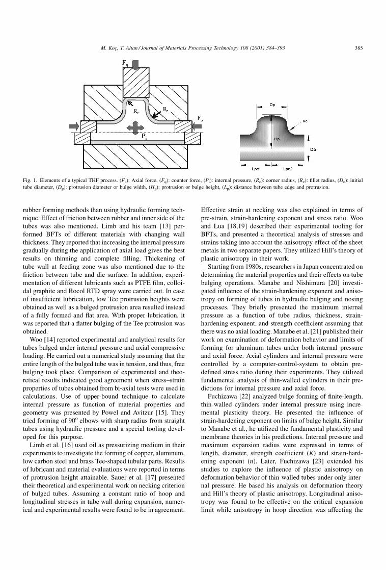
Fig. 1. Elements of a typical THF process. (Fa): Axial force, (Fq): counter force, (Pi): internal pressure, (Rc): corner radius, (Re): ®llet radius, (Do): initial
tube diameter, (Dp): protrusion diameter or bulge width, (Hp): protrusion or bulge height, (Lp): distance between tube edge and protrusion.
M. KocË, T. Altan / Journal of Materials Processing Technology 108 (2001) 384±393 385
maximum internal pressure required. With increasing ani-
sotropy in longitudinal axis, thinning is reduced while
obtainable expansion gets larger with less internal pressure
requirement. Experimental results were eventually com-
pared with theoretical ®ndings [24]. Different materials
including aluminum, brass and copper were tested in their
tooling, which only utilized internal pressure in a closed
cavity. Assuming that the tube materials obey power law of
strain hardening, experimental and calculated results were
found to be in good agreement. Studies of Manabe and
Fuchizawa on anisotropy effects were mostly found useful in
THF applications involving aluminum products.
Hydraulic bulging of tubes was later used in determining
the stress±strain characteristics of tubular materials by
Fuchizawa et al. [25]. Annealed aluminum, copper, brass
and titanium tubes were tested under only internal pressure.
With the instrumentation and control systems available, tube
thickness, radius of curvature in both longitudinal and hoop
directions, and internal pressure measured and recorded
during formation of the bulge. Using analytical methods
by membrane and plasticity theories, stress±strain relations
were derived. These ®ndings were also compared with those
obtained from tensile tests. Stress±strain relations for alu-
minum, copper and brass were found to be similar by two
tests, whereas that for titanium were different. Since they did
not use axial compressive load during bulging, stress±strain
relation obtained was limited to low strain values up to 0.7.
Thiruvarudchelvan [26] and his team have worked on
experimental and theoretical aspects of tube bulging process
using both polyurethane and liquid as pressurizing medium.
They used computers to control the process parameters and
for data acquisition in their experimental systems. Optimum
values for axial forces were de®ned to obtain large bulge
heights of tubes without any fracture [27,28]. Ueda [29,30]
presented forming of differential gear casings with hydro-
forming techniques after a series of experimentations in
1980s. Hashimi and his team [31±33] investigated the bulge
forming of axisymmetric and asymmetric components via
experiments, analytical techniques and FEA. Tonghai et al.
[34] presented their experimental and analytical work for
forming of Tee protrusions using polyurethane. Upper-
bound technique was used to predict total forming load.
As a major contribution, use of counter force and its effect
on attainable Tee protrusion height were investigated and
discussed. Use of upper-bound technique in calculation of
maximum internal pressure and axial force was also pre-
sented in another work [35]. Free bulging of aluminum tubes
was conducted, and results were compared with theoretical
solutions. Stress ratios between ÿ1 and 0 were found to be
the optimum range for bi-axial forming of tubes. However,
practical dif®culty to maintain the stress ratio in this zone
was also reported.
Finally, Dohmann and many of his students have been
working on various issues related to THF technology since
early 1980s [36]. Their work was mostly based on the
previous theoretical studies along with real and new indus-
trial applications of this technology [37]. They also utilized
the capabilities of continuously developing FEA and com-
puter controls in their experimental and analytical works
[38,39]. They have established formability diagrams for
different materials under certain circumstances in order to
speed up the practical use of the technology [40].
Controlling of process parameters and investigation of
possible part types were investigated by Schmoeckel and his
students in Darmstadt, Germany [41]. Forming of crank-
shaft-like parts using thick-walled tubes were performed
under experimental conditions [42,43]. They have also used
principle theories for prediction of process parameters, and
applied them into practical industrial use. Their work has
been heavily based on experiments for different aspects of
the technology including formability and producibility of
certain automotive parts, and tribological issues like lubri-
cation, die surface ®nish and wear [44]. THF parts were ®rst
classi®ed by Engel and Dick [43] as part of his dissertation
on development of fuzzy control systems for hydroforming
process. He grouped parts with respect to: (a) their variation
along longitudinal axis, (b) variation of the feature position
relative to the longitudinal axis and (c) variation of the cross-
section. Categorization of parts depending on their shape
complexity was also conducted. However, this classi®cation
was limited with only parts in exhaust systems excluding
structural frame parts, whereas KocË and Altan [45] consid-
ered structural parts such as frame rails, axles, cradles, etc. in
their classi®cation along with exhaust components. Their
classi®cation was based on: (a) spline geometry, (b) com-
mon feature types, (c) cross-section of tubes and (d) ratio of
length to diameter (L/D).
Use of FEA for THF process simulations is now a
standard development tool after investigations and valida-
tions conducted by many researchers since early 1990s.
Application of current commercial FEA software, such as
LS-DYNA, PAM-STAMP, ABAQUS, MARC, AUTO-
FORM, DEFORM, etc., for stamping and forging processes
into THF was performed and presented successfully [45±
47]. Consequent and seamless simulation of bending, pre-
forming and hydroforming, and sometimes annealing,
results in accurate predictions in terms of producibility,
formability and thinning of the desired part as well as points
out necessary changes in tool design. In order to shorten the
development time and efforts for THF process, supplemental
codes and techniques are being developed. Adaptive simu-
lation technique, for instance, iterates between appropriate
internal pressure and axial feeding inputs to ensure a part
without any fracture and wrinkles [48,49].
Various authors have presented their application and
practical oriented studies in numerous occasions since the
beginning of 1990s. The following issues were common
topics of these presentations [50±57]:
� industrial applications of THF technology,
� production of structural frame components,
� product development and design procedures,
386 M. KocË, T. Altan / Journal of Materials Processing Technology 108 (2001) 384±393
� evaluation of hydroformed parts in comparison to
stampings,
� incorporation of piercing into hydroforming tooling,
� assembly and welding issues,
� weight savings, etc.
2. THF parts, technology, presses, hydraulic andcontrol systems
Various parts for automotive, appliance and plumbing are
produced by THF technology as listed below:
� Exhaust system parts; usually made of stainless steel for
obtaining required structural, thermal and corrosion pro-
perties: Exhaust parts, engine tubes, catalytic converters,
pressure tubes, tail pipes, connectors and manifolds.
� Chassis parts; common material is low to medium carbon
steels and aluminum for structural and cost related rea-
sons: Frame rails, engine sub-frames (cradles), roof rails
and bows, instrument panels, rear axle frames and radiator
frames.
� Engine and power train components: Suspension cross
members, hollow camshafts, drive shafts and gear shafts.
� Body and safety parts: Windshield headers, A/B/C pillars,
space frame components, seat frames and shock absorber
housings.
Design of the THF system is of special importance since
high hydraulic pressures and complex shaped parts involved.
The system needed for THF consists of the followings:
� presses or clamping devices for closing the dies,
� tooling,
� pressure system; intensifier,
� hydraulic cylinders and punches; for sealing the tube and
move the material,
� process control systems; computers, data acquisition,
transducers, etc.
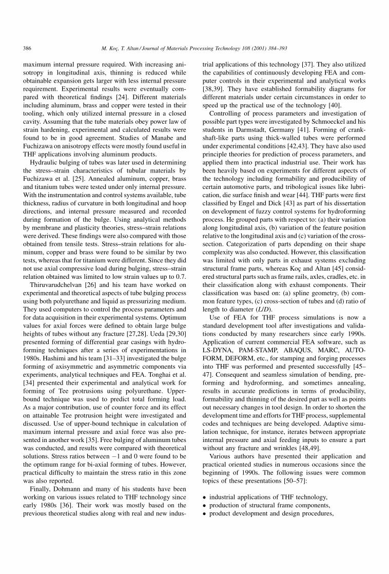
Fig. 2 illustrates examples of THF parts for automotive
applications. There are also a number of candidate parts in
development, such as camshaft, crankshafts, differential
casings and space frames [58].
2.1. Presses or clamping devices
In contrast to other forming operations, in THF process,
presses are used to open and close the die and to provide
enough clamping load during forming period to prevent
elastic de¯ections and die separation. Necessary tonnage of
the press (or clamping device) is dependent on the required
closing force. It is, in turn, a function of the maximum
internal pressure takes place during forming, part size (i.e.
diameter, length and thickness), and material. Large com-
ponents with thick walls (i.e. chassis components) and
intricate regions (i.e. small corner radii) need high closing
forces up to 7000±8000 t [60]. At present, presses up to
10 000 t capacity are in operation at several plants in the
world. Existing hydraulic presses with appropriate closing
forces and bed sizes can be utilized for THF process [55,60±
64] with some necessary additions and changes in the
system.
Clamping devices, other than regular hydraulic press
systems, are being designed and tested for hydroforming
purposes [65]. The purpose of developing special clamping
devices is to increase capabilities on process control, obtain
better dimensional accuracy via high clamping load, access
larger bed size, reduce cycle time, increase ¯exibility for
different parts and reduce investments, etc. In such a design,
the ram with the upper die half is actuated up and down
through a small cylinder, which would provide rapid motion
and cost less. As the ram closes the dies at its bottom
position, two opposite and horizontally positioned cylinders
are actuated to lock the ram at its required location. More-
over, several other small and short-stroke cylinders at the
bottom of the press bed are moved up to further increase the
clamping load capability. Such a design would not only be
cost effective in terms of initial capital investment, but also
would provide rapid stroking, which consequently contri-
bute reducing the production cost. In principal, a THF press
or machine must have the following features:
� appropriate die closing force;
� appropriate bed size to hold the dies;
� adjustable/movable axial punches with computer con-
trolled positioning;
Fig. 2. Examples of structural frame parts for automobile applications. In (a) roof headers (A), instrument panels (B), radiator frame (C), engine cradle and
rear axle (D), roof rails (E) and lower rail frames (F) can be manufactured by THF [56], (b) exhaust part [59], (c) space frame.
M. KocË, T. Altan / Journal of Materials Processing Technology 108 (2001) 384±393 387
� adjustable/movable rams for counter forces with free and
position control;
� optional: automatic work-piece handling;
� high pressure (2000±5000 bar) and fluid pumping cap-
ability with tight control.
2.2. Tooling
Hydroforming tooling consists of die holders, dies,
inserts, punches, sealing systems and sometimes counter
punches or movable inserts. Due to the high-pressure values
involved in THF process, strong tooling systems are required
to minimize die de¯ection and part tolerance deviations.
Hence, tool steel such as D2 are used for inserts, whereas
1045 steel is used for the dies. Inserts are usually hardened
and polished to achieve smooth surface ®nish to reduce
friction and die wear. Design of part positioning and parting
lines requires full attention since through which not only
necessary closing force can be reduced but also formability
of the part can be guaranteed. For structural parts, diagonal
positioning is one way of balancing the die de¯ection
between vertical and horizontal directions of the part.
Because of con®dentiality issues in this high demanding
technology, limited information regarding tooling design is
released to the public as it goes with other aspects of the
technology. Hence, common guidelines known for forging
and stamping technologies are applied in combination after
necessary improvements and trials.
In general, the followings are main requirements for THF
tooling [55,66±68]:
� high strength against stresses due to large internal pres-
sure and axial loading;
� good surface finish to minimize friction and increase
formability;
� flexibility by interchangeable inserts;
� good guiding systems;
� balanced design to minimize the closing force require-
ments.
2.3. Pressure system
The pressure system (pump, intensi®er and control
valves) should be designed and selected, so as to provide
the required pressure levels for a wide range of parts to
obtain ¯exibility in the system invested. The applied pres-
sure should have a range from 2000 bar (30 ksi) up to
10 000 bar (150 ksi) depending on the parts in consideration
[69]. In many current industrial applications using pressures
up to 3000 bar (45 ksi) are suf®cient. The ¯ow rate can reach
up to 50 l/min in order to allow short cycle times. In order to
increase the production rate, multiple intensi®ers are used to
shorten the pressurizing period and compensate time losses
in case of rapid pressure increases when required by any part
and process design.
2.4. Hydraulic cylinders and punches
The axial punches are necessary to: (a) seal the end of the
tube to avoid pressure losses and (b) feed material into
expansion regions. They should feed the material into the
deformation zone in a controlled way, and in synchroniza-
tion with internal pressure, i.e. pressure versus time and axial
force versus time should be controlled and coordinated.
Counter punches are sometimes used on bulged or protru-
sion sections to avoid premature fracture by providing a
controlled material ¯ow. Axial cylinders are expected to
generate forces of up to 7000 kN (700 t) while counter
cylinder limits extend up to 2000 kN (200 t). The smaller
size also allows close control of the punch position. Various
punch tip designs for effective sealing during hydroforming
have been developed. More information can be found in [67].
3. Materials and formability in THF
The overall success of hydroforming product heavily
depends on the incoming tubular material properties. Mate-
rial properties such as composition, weld type, yield and
tensile strength, ductility, anisotropy must be determined for
tubes. Monitoring and controlling of tube rolling, welding
and annealing processes should be conducted carefully to
produce tubes with desired properties. Followings are the
required characteristics of tubular materials for quality THF
applications:
� high and uniform elongation;
� high strain-hardening exponent;
� low anisotropy;
� close mechanical and surface properties of weld line to
the base material;
� good surface quality, free of scratches;
� close dimensional tolerances (thickness, diameter and
shape);
� burr free ends; should be brushed;
� tube edges perpendicular to the longitudinal axis.
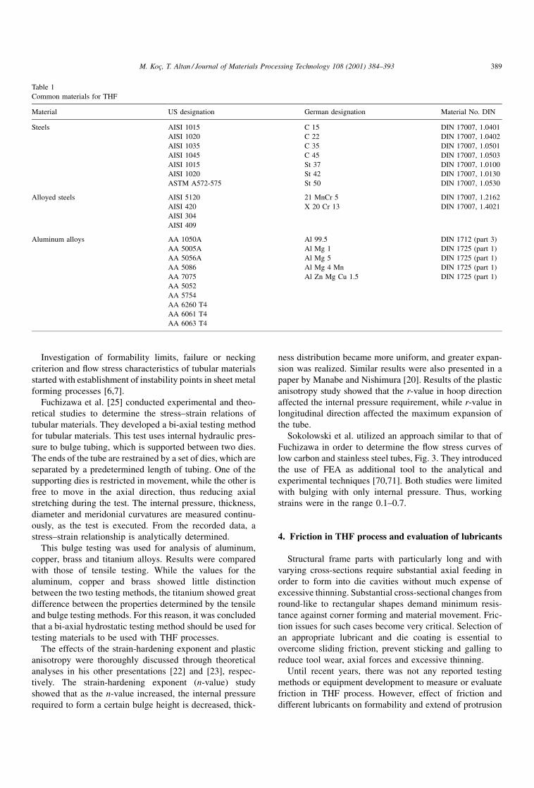
According to the requirements above, all alloys that are
used in deep drawing or extrusion are suitable for THF.
Table 1 tabulates some of the tubular materials used in THF
process. In addition, available tube types can be listed as
follows:
� seamless drawn circular tubes;
� seamless drawn tubular profiles;
� longitudinally seam welded circular tubes;
� longitudinally seam welded tubular profiles;
� tailored tubes; round seam welded or longitudinally seam
welded.
Different testing methods have been used to determine the
quality of tubing for purposes other than THF process [70].
These tests can be listed as follows: (a) tensile test, (b)
expansion test (c) cone test and (d) bulge test.
388 M. KocË, T. Altan / Journal of Materials Processing Technology 108 (2001) 384±393
Investigation of formability limits, failure or necking
criterion and ¯ow stress characteristics of tubular materials
started with establishment of instability points in sheet metal
forming processes [6,7].
Fuchizawa et al. [25] conducted experimental and theo-
retical studies to determine the stress±strain relations of
tubular materials. They developed a bi-axial testing method
for tubular materials. This test uses internal hydraulic pres-
sure to bulge tubing, which is supported between two dies.
The ends of the tube are restrained by a set of dies, which are
separated by a predetermined length of tubing. One of the
supporting dies is restricted in movement, while the other is
free to move in the axial direction, thus reducing axial
stretching during the test. The internal pressure, thickness,
diameter and meridonial curvatures are measured continu-
ously, as the test is executed. From the recorded data, a
stress±strain relationship is analytically determined.
This bulge testing was used for analysis of aluminum,
copper, brass and titanium alloys. Results were compared
with those of tensile testing. While the values for the
aluminum, copper and brass showed little distinction
between the two testing methods, the titanium showed great
difference between the properties determined by the tensile
and bulge testing methods. For this reason, it was concluded
that a bi-axial hydrostatic testing method should be used for
testing materials to be used with THF processes.
The effects of the strain-hardening exponent and plastic
anisotropy were thoroughly discussed through theoretical
analyses in his other presentations [22] and [23], respec-
tively. The strain-hardening exponent (n-value) study
showed that as the n-value increased, the internal pressure
required to form a certain bulge height is decreased, thick-
ness distribution became more uniform, and greater expan-
sion was realized. Similar results were also presented in a
paper by Manabe and Nishimura [20]. Results of the plastic
anisotropy study showed that the r-value in hoop direction
affected the internal pressure requirement, while r-value in
longitudinal direction affected the maximum expansion of
the tube.
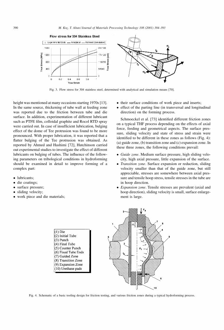
Sokolowski et al. utilized an approach similar to that of
Fuchizawa in order to determine the ¯ow stress curves of
low carbon and stainless steel tubes, Fig. 3. They introduced
the use of FEA as additional tool to the analytical and
experimental techniques [70,71]. Both studies were limited
with bulging with only internal pressure. Thus, working
strains were in the range 0.1±0.7.
4. Friction in THF process and evaluation of lubricants
Structural frame parts with particularly long and with
varying cross-sections require substantial axial feeding in
order to form into die cavities without much expense of
excessive thinning. Substantial cross-sectional changes from
round-like to rectangular shapes demand minimum resis-
tance against corner forming and material movement. Fric-
tion issues for such cases become very critical. Selection of
an appropriate lubricant and die coating is essential to
overcome sliding friction, prevent sticking and galling to
reduce tool wear, axial forces and excessive thinning.
Until recent years, there was not any reported testing
methods or equipment development to measure or evaluate
friction in THF process. However, effect of friction and
different lubricants on formability and extend of protrusion
Table 1
Common materials for THF
Material US designation German designation Material No. DIN
Steels AISI 1015 C 15 DIN 17007, 1.0401
AISI 1020 C 22 DIN 17007, 1.0402
AISI 1035 C 35 DIN 17007, 1.0501
AISI 1045 C 45 DIN 17007, 1.0503
AISI 1015 St 37 DIN 17007, 1.0100
AISI 1020 St 42 DIN 17007, 1.0130
ASTM A572-575 St 50 DIN 17007, 1.0530
Alloyed steels AISI 5120 21 MnCr 5 DIN 17007, 1.2162
AISI 420 X 20 Cr 13 DIN 17007, 1.4021
AISI 304
AISI 409
Aluminum alloys AA 1050A Al 99.5 DIN 1712 (part 3)
AA 5005A Al Mg 1 DIN 1725 (part 1)
AA 5056A Al Mg 5 DIN 1725 (part 1)
AA 5086 Al Mg 4 Mn DIN 1725 (part 1)
AA 7075 Al Zn Mg Cu 1.5 DIN 1725 (part 1)
AA 5052
AA 5754
AA 6260 T4
AA 6061 T4
AA 6063 T4
M. KocË, T. Altan / Journal of Materials Processing Technology 108 (2001) 384±393 389
height was mentioned at many occasions starting 1970s [13].
In the same source, thickening of tube wall at feeding zone
was reported due to the friction between tube and die
surface. In addition, experimentation of different lubricant
such as PTFE ®lm, colloidal graphite and Rocol RTD spray
were carried out. In case of insuf®cient lubrication, bulging
effect of the dome of Tee protrusion was found to be more
pronounced. With proper lubrication, it was reported that a
¯atter bulging of the Tee protrusion was obtained. As
reported by Ahmed and Hashimi [72], Hutchinson carried
out experimental studies to investigate the effect of different
lubricants on bulging of tubes. The in¯uence of the follow-
ing parameters on tribological conditions in hydroforming
should be examined in detail to improve forming of a
complex part:
� lubricants;
� die coatings;
� surface pressure;
� sliding velocity;
� work piece and die materials;
� their surface conditions of work piece and inserts;
� effect of the parting line (in transversal and longitudinal
direction) on the forming process.
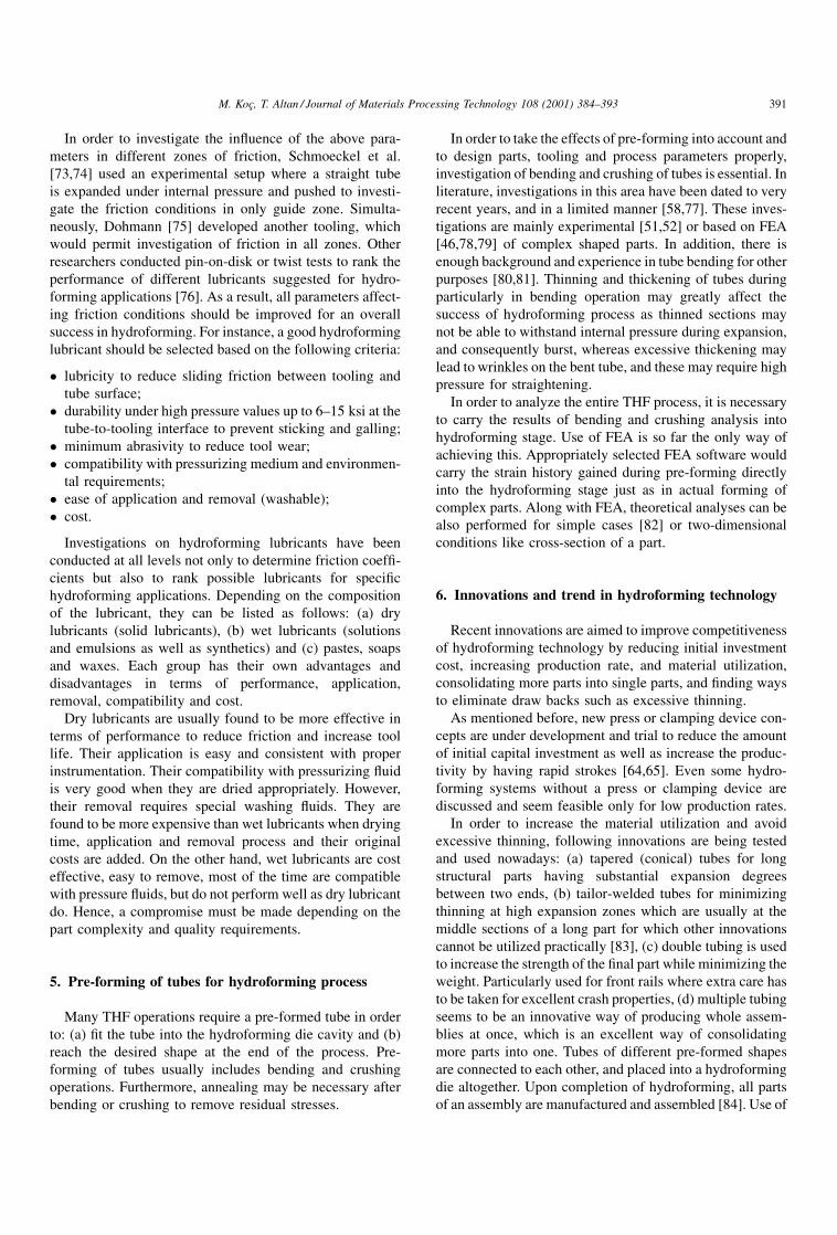
Schmoeckel et al. [73] identi®ed different friction zones
on a typical THF process depending on the effects of axial
force, feeding and geometrical aspects. The surface pres-
sure, sliding velocity and state of stress and strain were
identi®ed to be different in these zones as follows (Fig. 4):
(a) guide zone, (b) transition zone and (c) expansion zone. In
these three zones, the following conditions prevail:
� Guide zone. Medium surface pressure, high sliding velo-
city, high axial pressure, little expansion of the surface.
� Transition zone. Surface expansion or reduction, sliding
velocity smaller than that of the guide zone, but still
appreciable, stresses are somewhere between axial pres-
sure and tensile hoop stress, tensile stresses in the tube are
in hoop direction.
� Expansion zone. Tensile stresses are prevalent (axial and
hoop direction), sliding velocity is small, surface enlarge-
ment is large.
Fig. 3. Flow stress for 304 stainless steel, determined with analytical and simulation means [70].
Fig. 4. Schematic of a basic tooling design for friction testing, and various friction zones during a typical hydroforming process.
390 M. KocË, T. Altan / Journal of Materials Processing Technology 108 (2001) 384±393
In order to investigate the in¯uence of the above para-
meters in different zones of friction, Schmoeckel et al.
[73,74] used an experimental setup where a straight tube
is expanded under internal pressure and pushed to investi-
gate the friction conditions in only guide zone. Simulta-
neously, Dohmann [75] developed another tooling, which
would permit investigation of friction in all zones. Other
researchers conducted pin-on-disk or twist tests to rank the
performance of different lubricants suggested for hydro-
forming applications [76]. As a result, all parameters affect-
ing friction conditions should be improved for an overall
success in hydroforming. For instance, a good hydroforming
lubricant should be selected based on the following criteria:
� lubricity to reduce sliding friction between tooling and
tube surface;
� durability under high pressure values up to 6±15 ksi at the
tube-to-tooling interface to prevent sticking and galling;
� minimum abrasivity to reduce tool wear;
� compatibility with pressurizing medium and environmen-
tal requirements;
� ease of application and removal (washable);
� cost.
Investigations on hydroforming lubricants have been
conducted at all levels not only to determine friction coef®-
cients but also to rank possible lubricants for speci®c
hydroforming applications. Depending on the composition
of the lubricant, they can be listed as follows: (a) dry
lubricants (solid lubricants), (b) wet lubricants (solutions
and emulsions as well as synthetics) and (c) pastes, soaps
and waxes. Each group has their own advantages and
disadvantages in terms of performance, application,
removal, compatibility and cost.
Dry lubricants are usually found to be more effective in
terms of performance to reduce friction and increase tool
life. Their application is easy and consistent with proper
instrumentation. Their compatibility with pressurizing ¯uid
is very good when they are dried appropriately. However,
their removal requires special washing ¯uids. They are
found to be more expensive than wet lubricants when drying
time, application and removal process and their original
costs are added. On the other hand, wet lubricants are cost
effective, easy to remove, most of the time are compatible
with pressure ¯uids, but do not perform well as dry lubricant
do. Hence, a compromise must be made depending on the
part complexity and quality requirements.
5. Pre-forming of tubes for hydroforming process
Many THF operations require a pre-formed tube in order
to: (a) ®t the tube into the hydroforming die cavity and (b)
reach the desired shape at the end of the process. Pre-
forming of tubes usually includes bending and crushing
operations. Furthermore, annealing may be necessary after
bending or crushing to remove residual stresses.
In order to take the effects of pre-forming into account and
to design parts, tooling and process parameters properly,
investigation of bending and crushing of tubes is essential. In
literature, investigations in this area have been dated to very
recent years, and in a limited manner [58,77]. These inves-
tigations are mainly experimental [51,52] or based on FEA
[46,78,79] of complex shaped parts. In addition, there is
enough background and experience in tube bending for other
purposes [80,81]. Thinning and thickening of tubes during
particularly in bending operation may greatly affect the
success of hydroforming process as thinned sections may
not be able to withstand internal pressure during expansion,
and consequently burst, whereas excessive thickening may
lead to wrinkles on the bent tube, and these may require high
pressure for straightening.
In order to analyze the entire THF process, it is necessary
to carry the results of bending and crushing analysis into
hydroforming stage. Use of FEA is so far the only way of
achieving this. Appropriately selected FEA software would
carry the strain history gained during pre-forming directly
into the hydroforming stage just as in actual forming of
complex parts. Along with FEA, theoretical analyses can be
also performed for simple cases [82] or two-dimensional
conditions like cross-section of a part.
6. Innovations and trend in hydroforming technology
Recent innovations are aimed to improve competitiveness
of hydroforming technology by reducing initial investment
cost, increasing production rate, and material utilization,
consolidating more parts into single parts, and ®nding ways
to eliminate draw backs such as excessive thinning.
As mentioned before, new press or clamping device con-
cepts are under development and trial to reduce the amount
of initial capital investment as well as increase the produc-
tivity by having rapid strokes [64,65]. Even some hydro-
forming systems without a press or clamping device are
discussed and seem feasible only for low production rates.
In order to increase the material utilization and avoid
excessive thinning, following innovations are being tested
and used nowadays: (a) tapered (conical) tubes for long
structural parts having substantial expansion degrees
between two ends, (b) tailor-welded tubes for minimizing
thinning at high expansion zones which are usually at the
middle sections of a long part for which other innovations
cannot be utilized practically [83], (c) double tubing is used
to increase the strength of the ®nal part while minimizing the
weight. Particularly used for front rails where extra care has
to be taken for excellent crash properties, (d) multiple tubing
seems to be an innovative way of producing whole assem-
blies at once, which is an excellent way of consolidating
more parts into one. Tubes of different pre-formed shapes
are connected to each other, and placed into a hydroforming
die altogether. Upon completion of hydroforming, all parts
of an assembly are manufactured and assembled [84]. Use of
M. KocË, T. Altan / Journal of Materials Processing Technology 108 (2001) 384±393 391
aluminum alloys and high strength steel is seen as another
way of achieving lighter parts.
Companies and institutes are looking into every chance
and opportunity to make cost effective production with
lighter and stronger products. For instance, consolidation
of lubrication into tube making is considered one way of
increasing production rate. Application of various welding
types, such as gas metal arc welding, laser welding, electron
beam welding, is investigated to search better material
properties. Tube making (forming) cells are in consideration
instead of conventional tube rolling mills in some justi®able
cases.
As a result, almost all aspects of hydroforming technology
require full attention of researchers for better understanding
of its details. Generally, trend in this technology seem to
follow the same development path of other metal forming
processes.
References
[1] J.E. Grey, A.P. Devereaux, W.N. Parker, Apparatus for making
wrought metal T's, US Patent 2,203,868 June (1939).
[2] E.A. Davis, Yield and fracture of medium-carbon steel under
combined stress, J. Appl. Mech. (March 1945) A13±A24.
[3] J.H. Faupel, Yield and bursting characteristics of heavy wall
cylinders, Trans. ASME ( July 1956).
[4] B. Crossland, S.M. Jorgensen, J.A. Bones, The strength of thick-
walled cylinders, ASME J. Eng. Ind. (May 1959).
[5] H. Dietmann, The ¯ow behavior of thick-walled cylinders under
internal pressure, Bander Bleche Rohre 8 (3) (1967) 143±149 (in
German).
[6] P.B. Mellor, The ultimate tensile strength of thin-walled shells and
circular diaphgrams subjected to hydrostatic pressure, Int. J. Mech.
Sci. 1 (1960) 216±228.
[7] N.A. Weil, Tensile instability of thin-walled cylinders of ®nite length,
Int. J. Mech. Sci. 5 (1963) 487±506.
[8] D.M. Woo, The analysis of axisymmetric forming of sheet metal and
the hydrostatic bulging process, Int. J. Mech. Sci. 6 (1964) 303±317.
[9] F.J. Fuchs, Hydrostatic pressure Ð its role in metal forming, Mech.
Eng. (April 1966) 34±40.
[10] T. Ogura, T. Ueda, Liquid bulge forming, Metalworking Prod. (April
1968) 73±81.
[11] H.A. Al-Qureshi, P.B. Mellor, S. Garber, Application of polyurethane
to the bulging and piercing of thin-walled tubes, in: Proceedings of
the Ninth International MTDR Conference, Birmingham, UK,
September 1968, pp. 319±338.
[12] H.A. Al-Qureshi, Comparison between the bulging of thin-walled
tubes using rubber forming technique and hydraulic forming process,
Sheet Metal Ind. (July 1970) 607±612.
[13] M.E. Limb, J. Chakrabarty, S. Garber, P.B. Mellor, The forming of
axisymmetric and asymmetric components from tube, in: Proceed-
ings of the 14th International MTDR Conference, 1973, pp. 799±805.
[14] D.M. Woo, Tube-bulging under internal pressure and axial force, J.
Eng. Mater. Technol. (October 1973) 219±223.
[15] G. Powel, B. Avitzur, Forming of tube by hydraulic pressure, in:
Proceedings of the NAMRC, Ontario, Canada, May 14±15, 1973,
pp. 65±83.
[16] M.E. Limb, J. Chakrabarty, S. Garber, W.T. Roberts, Hydraulic
forming of tubes, Sheet Metal Ind. (November 1976) 418±424.
[17] W.J. Sauer, A. Gotera, F. Robb, P. Huang, Free bulge forming of
tubes under internal pressure and axial compression, in: Proceedings
of the Sixth NAMRC, 1978, pp. 228±235.
[18] D.M. Woo, Development of a bulge forming process, Sheet Metal
Ind. (May 1978) 623±625.
[19] D.M. Woo, A. Lua, Plastic deformation of anisotropic tubes in
hydraulic bulging, J. Eng. Mater. Technol. 100 (1978) 421±425.
[20] K. Manabe, H. Nishimura, In¯uence of material properties in
forming of tubes, Bander Bleche Rohre 9 (1983).
[21] K. Manabe, S. Mori, K. Suzuki, H. Nishimura, Bulge forming of
thin-walled tubes by micro-computer controlled hydraulic press, Adv.
Technol. Plasticity 1 (1984) 279±284.
[22] S. Fuchizawa, In¯uence of strain hardening exponent on the
deformation of thin-walled tube of ®nite length subjected to
hydrostatic external pressure, Adv. Technol. Plasticity 1 (1984)
297±302.
[23] S. Fuchizawa, In¯uence of plastic anisotropy on deformation of thin-
walled tubes in bulge forming, Adv. Technol. Plasticity 2 (1987)
727±732.
[24] S. Fuchizawa, Deformation of metal tubes under hydrostatic bulge
forming with closed die, Adv. Technol. Plasticity 3 (1990) 1543±
1548.
[25] S. Fuchizawa, M. Narazaki, H. Yuki, Bulge test for determining
stress±strain characteristics of thin tubes, Adv. Technol. Plasticity
(1993) 488±493.
[26] S. Thiruvarudchelvan, A theory for the bulging of aluminum tubes
using urethane rod, J. Eng. Technol. (February 1989).
[27] S. Thiruvarudchelvan, A theory for initial yielding conditions in tube
bulging with a urethane rod, J. Mater. Process. Technol. 42 (1994)
61±74.
[28] S. Thiruvarudchelvan, G.L. Seed, H.E. Ang, Computer-monitored
hydraulic bulging of tubes, J. Mater. Process. Technol. 57 (1996)
182±188.
[29] T. Ueda, Differential gear casings for automobile is liquid bulge
forming process Ð Part 1, Sheet Metal Ind. Ð Metal Forming 60 (3)
(1983) 181±184.
[30] T. Ueda, Differential gear casings for automobile is liquid bulge
forming process Ð Part 2, Sheet Metal Ind. Ð Metal Forming 60 (4)
(1983) 220±222.
[31] M.S.J. Hashimi, Forming of tubular components from straight
tubings using combined axial load and internal pressure: theory
and experiment, in: Proceedings of the International Conference on
Development on Drawing of Metals, Metals Society, London, 1983,
pp. 146±155.
[32] M.S.J. Hashimi, R. Crampton, Hydraulic bulge forming of axisym-
metric and asymmetric components: comparison of experimental
results and theoretical predictions, in: Proceedings of the Interna-
tional MTDR Conference, 1985, pp. 541±549.
[33] M. Ahmed, M.S.J. Hashimi, Estimation of machine parameters for
hydraulic bulge forming of tubular components, J. Mater. Process.
Technol. 64 (1997) 9±23.
[34] W. Tonghai, S. Sheng, M. Dexiu, The research of tube bulging using
polyurethane under compound external forces and its application,
Adv. Technol. Plasticity (1993) 494±499.
[35] J. Tirosh, A. Neuberger, A. Shirizly, On tube expansion by internal
¯uid pressure with additional compressive stress, J. Mech. Sci. 38
(8±9) (1995) 839±851.
[36] F. Klaas, Expansion upsetting of tubes using internal high pressure
forming, Fortschr.-Berichte VDI Reihe 2, No. 142, VDI-Verlag,
DuÈsseldorf, 1987 (in German).
[37] F. Dohmann, P. Bieling, Theoretical basis and applications of
high pressure forming, Bleche Rohre Pro®le 38 (5) (1991) 379±
385.
[38] A. Bohm, Numerical Simulations for the Process of Internal High
Pressure Forming, Dissertation, University of Paderborn, Germany,
1993 (in German).
[39] F. Dohmann, C. Hartl, Liquid bulge forming as a ¯exible production
method, J. Mater. Process. Technol. 45 (1994) 377±382.
[40] F. Dohmann, C. Hartl, Hydroforming components for automotive
applications, Fabricator (February 1998) 30±38.
392 M. KocË, T. Altan / Journal of Materials Processing Technology 108 (2001) 384±393
[41] D. Schmoeckel, C. Hessler, B. Engel, Pressure control in hydraulic
tube forming, Ann. CIRP 41 (1) (1992) 311±314.
[42] B. Engel, Process Strategies for Internal High Pressure Forming,
Dissertation, University of Darmstadt, Germany, Shaker, 1996 (in
German).
[43] B. Engel, P. Dick, New forming spectrums with internal high pressure
forming process, unknown source, 1995 (in German).
[44] D. Schmoeckel, Personal contacts on friction experiments and
lubrication information exchange with T. Altan of ERC/NSM, The
Ohio State University, Columbus, OH, 1998.
[45] M. KocË, T. Altan, Development of guidelines for part, process and
tooling design in the tube hydroforming (THF) process Ð
classi®cation of the THF parts and analytical models for prediction
of process parameters, Report No. ERC/NSM-98-R-34, The Ohio
State University, Columbus, OH, October 1998.
[46] M. KocË, T. Altan, Application of 2D FEA for the THF process Ð
case studies and guidelines for axisymmetric parts, Report No. ERC/
NSM-99-R-19, The Ohio State University, Columbus, OH, May
1999.
[47] H. Singh, Simulation of hydroforming process, in: Proceedings of the
Automotive Tube Conference, Detroit, MI, April 26±27, 1999.
[48] T. Altan, M. KocË, Y. Aueulan, K. Tibari, Formability and design
issues in tube hydroforming, in: Proceedings of the International
Conference on Hydroforming, Stuttgart, Germany, October 11±12,
1999.
[49] E. Doege, R. Keesters, C. Rogers, Determination of optimized
control parameters for internal high pressure forming processes with
FEM, Sheet Metal (1998) 119±128.
[50] C. Bruggeman, S. Shah, THF process overview and applications, in:
Proceedings of the Innovations in Hydroforming Conference,
Nashville, TN, September 1996.
[51] B. Longhouse, An introduction to recognizing potential applications
and product design, in: Proceedings of the Second Annual
Automotive Tube Conference, TPA International, Detroit, MI, May
1997, pp. 137±171.
[52] B. Longhouse, Capabilities of pressure sequence hydroforming,
Practical Applications of Hydroforming Technology, Dearborn, MI,
October 1997.
[53] M. Mason, Tube hydroforming: advancement using separated
forming procedures, Brochure in THF Technology, Tube and Pipe
Association, Nashville, TN, September 1996.
[54] F.U. Leitloff, Hydroforming of automotive components with
Schaefer ASE method, EFB-Colloquium, Stuttgart, Germany, March
1996.
[55] F.U. Leitloff, Hydroforming Ð from feasibility analysis to series
production, in: Proceedings of the Second International Conference
on Innovations in Hydroforming Technology, Columbus, OH,
September 1997.
[56] G. Morphy, Tubular hydroforming: ability and ¯exibility of pressure
sequencing, in: Proceedings of the Tube and Pipe Association
Conference on Hydroforming, Chicago, USA, November 1997,
pp. 199±213.
[57] M. Murray, Advancements using sequenced forming pressures, in:
Proceedings of the Innovations in Hydroforming Technology, TPA
International, Nashville, TN, September 1996.
[58] D. Schmoeckel, P. Dick, C. Hielscher, Innovational possibilities of
internal high pressure forming with superimposed bending stresses,
Blech Rohre Pro®le 43 (1±2) (1996) 49±52 (in German).
[59] SchaÈfer Company, Technological Guidelines for ASE Components
Method: Forming by Internal High Pressure, Wilndorf, Germany,
1996.
[60] B. Viehweger, With water to the shape, Blech Rohre Pro®le (43)
(1±2) (1996) 36±39 (in German).
[61] H. Cherek, Part cost reductions in the hydroforming process, in:
Proceedings of the Second International Conference on Innovations
in Hydroforming Technology, Columbus, OH, September 1997.
[62] P. Bieling, Industrial applications of THF, in: Proceedings of the
Second International Conference on Innovations in Hydroforming
Technology, Columbus, OH, September 1997.
[63] W. Osen, Speci®c design concepts for hydroforming presses, in:
Proceedings of the International Conference on Hydroforming,
Stuttgart, Germany, October 12±13, 1999, pp. 139±148.
[64] A. Nottrott, Hydroforming machines and plants, in: Proceedings of
the International Conference on Hydroforming, Stuttgart, Germany,
October 12±13, 1999.
[65] M. Haussermann, R. Rieger, A. Scwager, K. Siegert, New press con-
cept for hydroforming, in: Proceedings of the International Conference
on Hydroforming, Stuttgart, Germany, October 12±13, 1999.
[66] A. Birkert, Tool and part design for hydroforming, in: Proceedings of
the International Conference on Hydroforming, Stuttgart, Germany,
October 12±13, 1999.
[67] M. Krei, State of the art of sealing for hydroforming, in: Proceedings
of the International Conference on Hydroforming, Stuttgart,
Germany, October 12±13, 1999.
[68] M. Breckner, Hydraulic systems for hydroforming, in: Proceedings of
the International Conference on Hydroforming, Stuttgart, Germany,
October 12±13, 1999.
[69] F. Klaas, Innovations in high pressure hydroforming, in: Proceedings
of the Second International Conference on Innovations in Hydro-
forming Technology, Columbus, OH, September 17, 1999.
[70] T. Sokolowski, K. Gerke, M. KocË, M. Ahmetoglu, T. Altan,
Evaluation of tube formability and material characteristics in tube
hydroforming, ERC/NSM Report No. THF/ERC/NSM-98-R-025,
The Ohio State University, Columbus, OH, 1998.
[71] M. KocË, Y. Aueulan, T. Altan, On the characteristics of tubular
materials for hydroforming Ð design rules, analysis and experi-
mentation, J. Mach. Tools Manuf. (2000), accepted for publication.
[72] M. Ahmed, M.S.J. Hashimi, Comparison of free and restrained bulge
forming by FEM simulation, J. Mater. Process. Technol. (63) (1997)
651±654.
[73] D. Schmoeckel, C. Hielscher, R. Huber, M. Prier, Internal high
pressure forming at PtU, PtU der Technischen Hochschule Darm-
stadt, 1997 (in German).
[74] M. Prier, D. Schmoeckel, Tribology of internal high pressure
forming, in: Proceedings of the International Conference on
Hydroforming, Stuttgart, Germany, October 12±13, 1999.
[75] F. Dohmann, Tribology in internal high pressure forming, Blech
Rohre Pro®le (October 1997) 36±39 (in German).
[76] G. Dalton, The role of lubricants in hydroforming, in: Proceedings of
the Automotive Tube Conference, Detroit, MI, April 26±27, 1999.
[77] F. Dohmann, C. Hartl, Hydrofoming Ð a method to manufacture
light-weight parts, J. Mater. Process. Technol. 60 (1996) 669±676.
[78] J. Hua, M. KocË, T. Altan, Application of ®nite element analysis for
the tube hydroforming (THF) process, Report No. ERC/NSM-99-R-
4, The Ohio State University, Columbus, OH, January 1999.
[79] F. Hurton, Using forming simulation in development of complex
hydroformed shapes, in: Proceedings of the Second International
Conference on Innovations in Hydroforming Technology, Columbus,
OH, September 1997.
[80] R.T. Zhang, J.L. Duncan, Strain Modeling and Measurement in Tube
Bending, SAE No. 960825, 1996.
[81] T. Granelli, Applying tube bending fundamentals to production, in:
Proceedings of the Second International Conference on Innovations
in Hydroforming Technology, Columbus, OH, September 17, 1997.
[82] A. Shr, M. KocË, M. Ahmetoglu, T. Altan, Bending of tubes for
hydroforming: a state of the art review and analysis, ERC/NSM
Report-99-R-1-THF Ohio State University, Columbus, Ohio, USA,
1999.
[83] A. Eichhorn, Innovative developments concerning hydroforming of
tubes, in: Proceedings of the International Conference on Hydro-
forming, Stuttgart, Germany, October 12±13, 1999.
[84] C.J. Bruggeman, Hydroforming of structure parts for personnel cars,
in: Proceedings of the International Conference on Hydroforming,
Stuttgart, Germany, October 12±13, 1999.
M. KocË, T. Altan / Journal of Materials Processing Technology 108 (2001) 384±393 393
Related Documents