INTERNATIONAL JOURNAL OF PRECISION ENGINEERING AND MANUFACTURING Vol. X, No. X, pp. X-XX XXXX 201X / 1 1. Introduction The Aerostatic Bearing Spindle (ABS) is a major component of the ultra-precision machine tools, and its dynamic performance determines the machining performance of ultra-precision machine tools. ABS is a complex electromechanical system, which contains both the mechanical and servo subsystems, 1 so dynamic characteristics of ABS are more complex, which are compared with conventional spindles. It is necessary for engineers to thoroughly realize the influences of the system parameters to the ABS dynamics with considering the multi-physics coupling property. 2 The detail structures of ABS are shown in Fig.1, which is mainly composed by a permanent magnet synchronous motor (PMSM) and aerostatic bearings. ABS can is divided into three parts: the grating ruler, the motor and the air bearings. In ABS, an air bearing system is directly connected with the motor, which cancel the intermediate transmission links. Because the spindle shaft of the ABS is directly driven by a motor, ABS can achieve high speed and precision which drastically increase productivity and reduce production cost. 3, 4 However, the direct drive mechanism causes ABS very sensitive to the variation of the work load. It also causes a strong feedback coupling between the machining process and the servo system. In common, the mechanical system and the servo system of ultra- precision machine tools are separately designed. Generally, Fig. 1 Schematic diagram of ABS there would be inevitable matching problems between the mechanical system and the servo system, which dynamically affect the system performance, especially in the ultra-precision machine requirements. Accordingly, to maintain the processing stability and reduce external interference on ABS, the electromechanical coupling design should be considered. At present, many scholars have considered dynamic characteristics, 5,6 thermal characteristics, 7 and static pressure characteristics 8, 9 during designing spindle systems, but rarely considered the integrated design for ABS. With the An Mechatronics Coupling Design Approach for Aerostatic Bearing Spindles Quanhui Wu 1 , Yazhou Sun 1 , Wanqun Chen 1 , Haitao Liu 1,# and Xichun Luo 2 1 School of Mechatronics Engineering, Harbin Institute of Technology, Harbin 150001, P. R. China 2 Centre for Precision Manufacturing, DMEM, University of Strathclyde, Glasgow G1 1XJ, UK # Corresponding Author / E-mail: [email protected]/ [email protected], TEL: + 86-0451-86413840, FAX: + 86-0451-86415244 KEYWORDS : Aerostatic bearing spindle, design, dynamic characteristics, electromechanical coupling In this paper, a new design approach for Aerostatic Bearing Spindles (ABS) is firstly proposed which takes into account of the interactions between the mechanical and the servo subsystems, including the integration of electromagnetic effects, static pressure characteristics, servo control and mechanical characteristics. According to the air bearing design principle, the geometry of the spindle rotor is designed. The fluid software is used to analyze the influence of the bearing capacity and stiffness on the stability of the spindle. The simulation shows when the air film thickness is 12μm, the bearing has good load carrying capacity and rigidity. In addition, the influence of motor harmonics on the spindle shaft modes is considered to avoid the resonance of ABS, and to ensure ABS anti-interference capability, proper inertia of ABS is calculated and analyzed. Finally, ABS has a good follow-up effect on the servo control and machining performance through the experimental prototype. The electromechanical coupling design approach for ABS proposed in this paper, can achieve a Peak Value (PV) better than 0.8μm (surface size: 9mm×9mm) and a surface roughness better than 8nm in end face turning experiments. Peer reviewed accepted author manuscript of the following research article Wu, Q., Sun, Y., Chen, W., Liu , H., & Luo, X. (2019). An mechatronics coupling design approach for aerostatic bearing spindles. International Journal of Precision Engineering and Manufacturing, 20(7), 1185-1196. https://doi.org/10.1007/s12541-019-00098-w

Welcome message from author
This document is posted to help you gain knowledge. Please leave a comment to let me know what you think about it! Share it to your friends and learn new things together.
Transcript
INTERNATIONAL JOURNAL OF PRECISION ENGINEERING AND MANUFACTURING Vol. X, No. X, pp. X-XX XXXX 201X / 1
1. Introduction
The Aerostatic Bearing Spindle (ABS) is a major component of
the ultra-precision machine tools, and its dynamic performance
determines the machining performance of ultra-precision machine
tools. ABS is a complex electromechanical system, which contains
both the mechanical and servo subsystems,1 so dynamic
characteristics of ABS are more complex, which are compared with
conventional spindles. It is necessary for engineers to thoroughly
realize the influences of the system parameters to the ABS dynamics
with considering the multi-physics coupling property.2 The detail
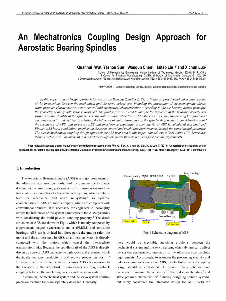
structures of ABS are shown in Fig.1, which is mainly composed by
a permanent magnet synchronous motor (PMSM) and aerostatic
bearings. ABS can is divided into three parts: the grating ruler, the
motor and the air bearings. In ABS, an air bearing system is directly
connected with the motor, which cancel the intermediate
transmission links. Because the spindle shaft of the ABS is directly
driven by a motor, ABS can achieve high speed and precision which
drastically increase productivity and reduce production cost.3, 4
However, the direct drive mechanism causes ABS very sensitive to
the variation of the work load. It also causes a strong feedback
coupling between the machining process and the servo system.
In common, the mechanical system and the servo system of ultra-
precision machine tools are separately designed. Generally,
Fig. 1 Schematic diagram of ABS
there would be inevitable matching problems between the
mechanical system and the servo system, which dynamically affect
the system performance, especially in the ultra-precision machine
requirements. Accordingly, to maintain the processing stability and
reduce external interference on ABS, the electromechanical coupling
design should be considered. At present, many scholars have
considered dynamic characteristics,5,6 thermal characteristics,7 and
static pressure characteristics8, 9 during designing spindle systems,
but rarely considered the integrated design for ABS. With the
An Mechatronics Coupling Design Approach for Aerostatic Bearing Spindles
Quanhui Wu1, Yazhou Sun1, Wanqun Chen1, Haitao Liu1,# and Xichun Luo2
1 School of Mechatronics Engineering, Harbin Institute of Technology, Harbin 150001, P. R. China 2 Centre for Precision Manufacturing, DMEM, University of Strathclyde, Glasgow G1 1XJ, UK
# Corresponding Author / E-mail: [email protected]/ [email protected], TEL: + 86-0451-86413840, FAX: + 86-0451-86415244
KEYWORDS : Aerostatic bearing spindle, design, dynamic characteristics, electromechanical coupling
In this paper, a new design approach for Aerostatic Bearing Spindles (ABS) is firstly proposed which takes into account
of the interactions between the mechanical and the servo subsystems, including the integration of electromagnetic effects,
static pressure characteristics, servo control and mechanical characteristics. According to the air bearing design principle,
the geometry of the spindle rotor is designed. The fluid software is used to analyze the influence of the bearing capacity and
stiffness on the stability of the spindle. The simulation shows when the air film thickness is 12μm, the bearing has good load
carrying capacity and rigidity. In addition, the influence of motor harmonics on the spindle shaft modes is considered to avoid
the resonance of ABS, and to ensure ABS anti-interference capability, proper inertia of ABS is calculated and analyzed.
Finally, ABS has a good follow-up effect on the servo control and machining performance through the experimental prototype.
The electromechanical coupling design approach for ABS proposed in this paper, can achieve a Peak Value (PV) better than
0.8μm (surface size: 9mm×9mm) and a surface roughness better than 8nm in end face turning experiments.
Peer reviewed accepted author manuscript of the following research article Wu, Q., Sun, Y., Chen, W., Liu , H., & Luo, X. (2019). An mechatronics coupling design
approach for aerostatic bearing spindles. International Journal of Precision Engineering and Manufacturing, 20(7), 1185-1196. https://doi.org/10.1007/s12541-019-00098-w

2 / XXXX 201X INTERNATIONAL JOURNAL OF PRECISION ENGINEERING AND MANUFACTURING Vol. X, No.X
increasing requirements of high precision and high efficiency for the
ultra-precision machining, the design method for the
electromechanical integration is becoming more and more urgent.
The traditional experience separation or step-by-step design method
is facing great challenge, because the coupling factors in the design
have been already inevitable problems.10 To meet the needs of the
machining development, many scholars have studied the impacts of
servo systems for improving movement accuracy of the mechanical
and electrical systems.11-14 In addition, to study servo control system
research, a PID controller to stabilize the system is adopted adaptive
feed forward cancellation to effectively compensate for the process
of driving the system of vibration.15 Also, a three-loop servo system
of the permanent magnet motor is studied.16 In order to improve the
control performance of the servo system, the control parameters are
optimized and the three-loop feedback is designed to enhance
stability and fast performance of the spindle system. Besides, to
increase motor performance, an electromechanical integrated
harmonic piezodrive system is proposed, and analyzed that the size
parameters of the stator had a certain influence on the natural
frequency of the drive system.17 The mechanical and electrical
integration to design the static pressure rail is proposed, containing
the mechanical parts and the servo parts.18 Moreover, to further study
the dynamic characteristics of the spindle, the machined surface
topography in the ultra-precision machining process is obviously
affected by the aerostatic bearings.19, 20 Therefore, machining
workpiece surface is an effective method for detecting the dynamic
performance of a spindle system. The above studies only consider the
relationship between the mechanical and servo systems and do not
take into account the influence of the electromagnetic effects of the
motor on its performance, or just study one of the factors in
electromechanical systems.
As ABS is a complex electromechanical coupling system, the
interaction of various factors affects the dynamic performance.
Coupling analysis of ABS is an inevitable problem, so the traditional
single research method has faced enormous challenges. Nowadays,
numerous of scholars have studied the effect of servo system on
improving the motion accuracy of electromechanical systems.
However, these studies mainly discuss the relationship between the
mechanical system and the servo system, but seldom consider the
motor characteristics. In fact, because the motor acts as a direct drive
source, its performance directly affects system performance. In
addition, the electromagnetic vibration of the motor acts on the
mechanical mode of ABS, which is easy to generate resonance and
affect the dynamic performance of the spindle system. As the air film
of ABS is used to support the spindle shaft, the static pressure
stiffness of ABS also has a certain influence on the dynamic
characteristics, which affect the resonance frequency of the spindle
shaft. Moreover, the inertia of the spindle shaft has a certain influence
on the servo system of ABS, which affects the stability. However,
the inertia of the spindle shaft is determined by its own volume, and
the volume is affected by the stiffness and load carrying capacity.
Therefore, the mechanical structure, the motor, the air supply and the
servo control interact with each other, and the coupling relationship
between them is shown in Fig.2. In order to
Fig. 2 Diagram of the electromechanical coupling approach
further improve dynamic performance of the direct drive system, it
is very important to consider the coupling effects of the three parts,
because the three complements influence each other, and only a
comprehensive consideration can enable the electromechanical
system to achieve better performance.
In this paper, an electromechanical coupling design approach for
an aerostatic bearing spindle system is proposed, and the multi- factor
dynamic studies of Aerostatic Bearing Spindle (ABS) are shown in
Fig.2. It considers the static pressure characteristics, mechanical
characteristics, electromagnetic characteristics and servo
characteristics as a whole, and takes into account the
electromechanical coupling effects. According to the design
specifications of ABS, the motor, the mechanical dimensions, the air
bearing system and control parameters of the spindle shaft are
designed. The harmonic frequency spectrum of the driven motor and
the mechanical characteristics of the spindle are analyzed. To
introduce the generic design approach, the following sessions will be
implantation of the approach through a design case. As an important
part of ultra-precision machine tools, this article will take an ABS as
a research object to illustrate the design, and the dynamic
characteristics of the ABS are evaluated by experiments.
2. Electromechanical coupling analysis
Before designing the spindle system, it should ensure that the
spindle system has the sufficient stability, rapid response capability,
and high positioning accuracy. Therefore, the spindle system should
have lighter quality, but it must ensure that it has a certain degree of
stiffness and inertia, which can resist external interference. In
addition, the spindle system uses a motor to directly drive the spindle
shaft. The electromagnetic harmonics generated by the motor also
have a certain influence on the mechanical structure, which should
be considered.
2.1 Selection of film thickness
The servo stiffness of ABS ensures the smoothness of the rotation,
but it cannot withstand the axial and radial interference from the
outside. The axial and radial ant interference ability requires thrust and
radial bearing guarantee. Considering that the air bearing system has
sufficient resistance to external disturbances, it is necessary to
INTERNATIONAL JOURNAL OF PRECISION ENGINEERING AND MANUFACTURING Vol. X, No. X, pp. X-XX XXXX 201X / 3
determine the axial and radial stiffness and bearing capacity of the air
bearing. In this paper, the throttling form of the small orifices is used
in the air bearings. The working principle is that air is pressed into the
air gap of the air bearings by each orifice, and the throttling principle
of orifice restrictors embedded in the air bearing is adopted. The radial
and axial loads are balanced by the radial bearing pressure difference
and the thrust bearing pressure difference, respectively. The air bearing
acts to support the rotation of the spindle shaft, ensuring the spindle
system has sufficient bearing capacity, radial and axial stiffness. Since
the air film size and air supply pressure directly affect its stiffness, it is
necessary to analyze its air film and supply pressure
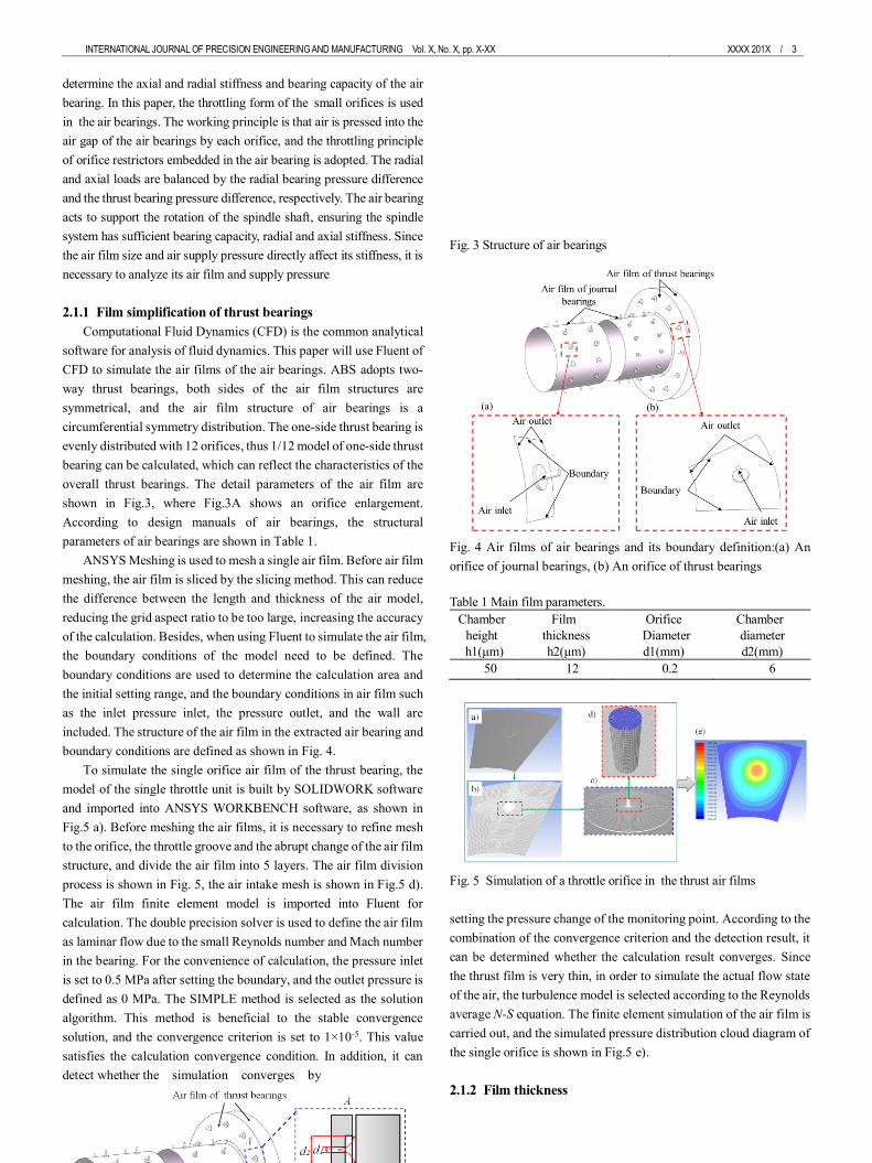
2.1.1 Film simplification of thrust bearings
Computational Fluid Dynamics (CFD) is the common analytical
software for analysis of fluid dynamics. This paper will use Fluent of
CFD to simulate the air films of the air bearings. ABS adopts two-
way thrust bearings, both sides of the air film structures are
symmetrical, and the air film structure of air bearings is a
circumferential symmetry distribution. The one-side thrust bearing is
evenly distributed with 12 orifices, thus 1/12 model of one-side thrust
bearing can be calculated, which can reflect the characteristics of the
overall thrust bearings. The detail parameters of the air film are
shown in Fig.3, where Fig.3A shows an orifice enlargement.
According to design manuals of air bearings, the structural
parameters of air bearings are shown in Table 1.
ANSYS Meshing is used to mesh a single air film. Before air film
meshing, the air film is sliced by the slicing method. This can reduce
the difference between the length and thickness of the air model,
reducing the grid aspect ratio to be too large, increasing the accuracy
of the calculation. Besides, when using Fluent to simulate the air film,
the boundary conditions of the model need to be defined. The
boundary conditions are used to determine the calculation area and
the initial setting range, and the boundary conditions in air film such
as the inlet pressure inlet, the pressure outlet, and the wall are
included. The structure of the air film in the extracted air bearing and
boundary conditions are defined as shown in Fig. 4.
To simulate the single orifice air film of the thrust bearing, the
model of the single throttle unit is built by SOLIDWORK software
and imported into ANSYS WORKBENCH software, as shown in
Fig.5 a). Before meshing the air films, it is necessary to refine mesh
to the orifice, the throttle groove and the abrupt change of the air film
structure, and divide the air film into 5 layers. The air film division
process is shown in Fig. 5, the air intake mesh is shown in Fig.5 d).
The air film finite element model is imported into Fluent for
calculation. The double precision solver is used to define the air film
as laminar flow due to the small Reynolds number and Mach number
in the bearing. For the convenience of calculation, the pressure inlet
is set to 0.5 MPa after setting the boundary, and the outlet pressure is
defined as 0 MPa. The SIMPLE method is selected as the solution
algorithm. This method is beneficial to the stable convergence
solution, and the convergence criterion is set to 1×10⁻⁵. This value
satisfies the calculation convergence condition. In addition, it can
detect whether the simulation converges by
Fig. 3 Structure of air bearings
Fig. 4 Air films of air bearings and its boundary definition:(a) An
orifice of journal bearings, (b) An orifice of thrust bearings
Table 1 Main film parameters.
Chamber
height
h1(μm)
Film
thickness
h2(μm)
Orifice
Diameter
d1(mm)
Chamber
diameter
d2(mm)
50 12 0.2 6
Fig. 5 Simulation of a throttle orifice in the thrust air films
setting the pressure change of the monitoring point. According to the
combination of the convergence criterion and the detection result, it
can be determined whether the calculation result converges. Since
the thrust film is very thin, in order to simulate the actual flow state
of the air, the turbulence model is selected according to the Reynolds
average N-S equation. The finite element simulation of the air film is
carried out, and the simulated pressure distribution cloud diagram of
the single orifice is shown in Fig.5 e).
2.1.2 Film thickness

4 / XXXX 201X INTERNATIONAL JOURNAL OF PRECISION ENGINEERING AND MANUFACTURING Vol. X, No.X
The small orifice diameter of the thrust air bearings is set to
0.2mm, 12 rows are evenly distributed in each row, and the radial
position is 78mm. Under different film thicknesses, the bearing
capacity and stiffness curve of the air supply pressure to the air
bearings are shown in Fig. 6 and Fig.7. Bearing capacity of the air
bearing decreases with the increase of the air film thickness, and the
bearing capacity decreases rapidly with the increase of the air gap
spacing. Fig.6 shows the bearing capacity curve of the air bearing
with the film gap. In addition, under different inlet pressures, the
bearing capacity of air bearings is different. As the inlet pressure
increases, the bearing capacity of the bearing increases continuously,
and the load capacity changes greatly in the range where the inlet
pressure film gap is small. The stiffness calculation of the air bearing
is carried out, and the calculation result is shown in Fig. 7. With the
increase of the air gap, the bearing stiffness increases first and then
decreases. The bearing stiffness reaches a peak at a film thickness of
12 μm. This value is the ideal thickness value for this thrust bearings.
In addition, the supply pressure also has a certain influence on the
stiffness. As the supply pressure increases, the bearing stiffness
increases, and the peak point reached by the bearing stiffness also
increases. In summary, a suitable film gap can increase bearing
stiffness and reduce air supply. When designing an aerostatic
bearing, the given range of the supply pressure should be taken into
account, and the fluctuation of the supply pressure should be reduced
to ensure the performance of the designed bearing.
2.1.3 Air supply pressure
Bearing capacity and stiffness of the air bearings are calculated
under different air supply pressures. The results are shown in Fig.8
and Fig.9. The film thickness is set to (a) 14μm, (b) 15μm and (c)
16μm. It can be seen from the calculation results that as the supply
pressure decreases, the bearing capacity of the air film decreases. As
the air bearing capacity increases, the air bearing stiffness decreases.
In addition, the flow rate under different supply pressures is
calculated. As the pressure increases, the air flow also increases
correspondingly, which is shown in Fig.10. Through analysis of the
air films and the inlet pressure of the air bearings, the design of the
air bearing can obtain the proper film thickness and supply pressure,
which not only ensures the bearing capacity and rigidity, but also
reduces the air consumption.
2.2 Spindle shaft geometry
The bearings are characterized by the geometric configurations,
so the restriction parameters and the optimization values of the
bearings are significant in the dynamic characteristics of ABS. 21 As
shown in Fig. 1, the spindle shaft adopts an integral structure of the
journal and axial bearings, and all the bearings adopt the small orifice
throttles. The spindle shaft structure uses two series of journal
bearings to increase the journal bearing capacity and stiffness, and
adopts two opposing axial bearings, which can be subjected to loads
coming from two directions, forward and reverse. Although two axial
bearings, which have the same sizes, reduce the
Fig. 6 Bearing capacity variation with film thickness
Fig. 7 Stiffness variation with film thickness
Fig. 8 Bearing capacity versus air pressure
Fig. 9 Bearing stiffness versus air pressure
Fig. 10 Air consumption with air pressure
load capacity of the spindle in the axial direction, it can increase the
axial stiffness. In addition, in order to reduce the spindle shaft

INTERNATIONAL JOURNAL OF PRECISION ENGINEERING AND MANUFACTURING Vol. X, No. X, pp. X-XX XXXX 201X / 5
deformation caused by the temperature rise of the drive motor, the
axial bearing of the spindle system adopts the front type, that is, the
axial bearing is installed at the end of the machining workpiece, and
the motor is installed the other end of the spindle shaft. Under this
layout condition, when the motor becomes heat, the spindle
deformation moves away from the axial bearing, avoiding the
influence on the machining shaft end. In addition, in order to achieve
the electromechanical optimization, the control system of the spindle
system requires the drive component weight as little as possible.
However, if the drive component weight is too little, the spindle
system could not guarantee the system's anti-interference. In order to
study the performances of the spindle shaft, the detail requirements
for the mechanical structure are put forward. To ensure ABS has
good thrust and radial anti-interference capability, the thrust stiffness
is better than 300N/μm, and the journal stiffness is better than
300N/μm.
It can be seen from Fig.1, the axial length of the spindle shaft is
selected taking into account the Grating ruler, motor and air bearings.
According to the axial length required for the three parts, the
influence of these factors should be considered in the design of the
spindle shaft. To ensure good response and a certain anti-interference
ability, the spindle shaft needs to be optimized. The outline
dimensions of the spindle shaft are shown in Fig. 11. L0 represents
the total length of the spindle shaft, L1 represents the axial bearing
length, L3 represents the axial length of the mounting motor (L3<L2),
L4 represents the axial size of the circular grating, L5 represents the
axial bearing thickness (L5<L6), and L7 represents the internal bore
length (L7<L1). Besides, D0 represents the outer diameter of the axial
bearing. D1 represents the diameter of the spindle shaft end, and this
end can be used to install a vacuum chuck or a three grasping chuck
for fixing the workpiece. D2 represents the journal bearing diameter,
and D3 represents the bore diameter, which is used to vacuum and
reduce the spindle mass. In order to ensure the sufficient strength of
the spindle shaft, the general diameter of the spindle meets D3≤D1
and D3≤ (1/2)D2. The spindle shaft length to diameter ratio is
L1/D2=0.75, the throttle position meets L8/L1 = 1/4. To improve the
control performance of the spindle system, and reduce the spindle
shaft quality, the geometric sizes of the spindle shaft should meet
L1+L2+L4+L6≤L0.
The journal and thrust air bearings are used for the spindle shaft,
and its features should be considered. Hence, the design of the journal
bearing is analyzed, which uses the double-row air supply and the
load capacity coefficient CJ=0.25, and the corresponding calculations
are expressed as Eqs. (1-3).
1 2 0J JW C L D p (1)
2 /J JK W (2)
2
1
1
16JK K L
(3)
Where P0=1×10⁵Pa is atmospheric pressure, ε denotes the
eccentricity, WJ denotes the bearing capacity, KJ denotes the stiffness,
and Kα denote the angular rigidity.
Fig. 11 Geometry of the spindle shaft
The axial bearings adopt the annular porous air supply, and the
structure performances meet the following requirements, which are
calculated as Eqs.(4-6).
2 2
2 1 0( )t tW C r r p (4)
02.88 /t JK W h (5)
2 1
1( )
8tK K r r (6)
Where r1 represents the inner radius, r2 represents the outer
radius, Wt represents the bearing capacity, Kt represents the stiffness,
Kα represents the angular rigidity, h0 represents the bearing air gap
size, and Ct represents the load capacity coefficient, respectively.
After above calculations, in order to ensure the spindle system has
sufficient strengths, the main dimensions of the spindle shaft are
shown in Table 2.
Table 2 Geometric sizes of the spindle
Symbol Length value[mm] Symbol Length value[mm]
L0 455 L7 266
L1 235 D0 190
L2 129 D1 90
L3 114 D2 100
L4 10 D3 50
L5 25 D4 50
L6 54 - -
2.3 Mechanical modal
Relative oscillations in the drive system, generated by the
mechanical structure, may cause the feedback position to oscillate. 22
Therefore, considering the performance of the spindle system, it can
be seen that the servo width of the spindle system should satisfy less
than the minimum width value of those systems. Thus, the vibration
of the servo system and the mechanical harmonic can be avoided,
which can improve and the control accuracy. Through the above
analysis, the performance of the spindle system can be improved by
adjusting the servo parameters or changing the mechanical system,
which allows the complementarities between the servo system and
mechanical system to achieve optimizations.
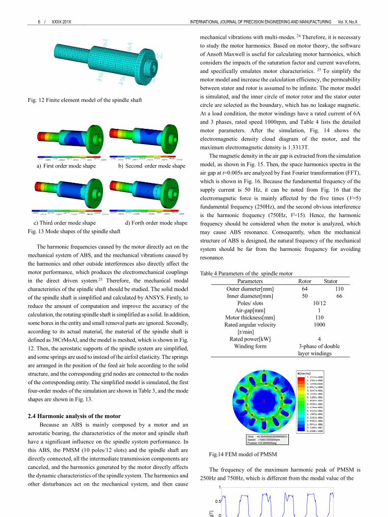
Table3 Mode values of the spindle shaft
First order Second order Third order Forth order
341.86Hz 359.12Hz 467.14 Hz 468.01 Hz
6 / XXXX 201X INTERNATIONAL JOURNAL OF PRECISION ENGINEERING AND MANUFACTURING Vol. X, No.X
Fig. 12 Finite element model of the spindle shaft
a) First order mode shape b) Second order mode shape
c) Third order mode shape d) Forth order mode shape
Fig. 13 Mode shapes of the spindle shaft
The harmonic frequencies caused by the motor directly act on the
mechanical system of ABS, and the mechanical vibrations caused by
the harmonics and other outside interferences also directly affect the
motor performance, which produces the electromechanical couplings
in the direct driven system.23 Therefore, the mechanical modal
characteristics of the spindle shaft should be studied. The solid model
of the spindle shaft is simplified and calculated by ANSYS. Firstly, to
reduce the amount of computation and improve the accuracy of the
calculation, the rotating spindle shaft is simplified as a solid. In addition,
some bores in the entity and small removal parts are ignored. Secondly,
according to its actual material, the material of the spindle shaft is
defined as 38CrMoAl, and the model is meshed, which is shown in Fig.
12. Then, the aerostatic supports of the spindle system are simplified,
and some springs are used to instead of the airfoil elasticity. The springs
are arranged in the position of the feed air hole according to the solid
structure, and the corresponding grid nodes are connected to the nodes
of the corresponding entity. The simplified model is simulated, the first
four-order modes of the simulation are shown in Table 3, and the mode
shapes are shown in Fig. 13.
2.4 Harmonic analysis of the motor
Because an ABS is mainly composed by a motor and an
aerostatic bearing, the characteristics of the motor and spindle shaft
have a significant influence on the spindle system performance. In
this ABS, the PMSM (10 poles/12 slots) and the spindle shaft are
directly connected, all the intermediate transmission components are
canceled, and the harmonics generated by the motor directly affects
the dynamic characteristics of the spindle system. The harmonics and
other disturbances act on the mechanical system, and then cause
mechanical vibrations with multi-modes. 24 Therefore, it is necessary
to study the motor harmonics. Based on motor theory, the software
of Ansoft Maxwell is useful for calculating motor harmonics, which
considers the impacts of the saturation factor and current waveform,
and specifically emulates motor characteristics. 25 To simplify the
motor model and increase the calculation efficiency, the permeability
between stator and rotor is assumed to be infinite. The motor model
is simulated, and the inner circle of motor rotor and the stator outer
circle are selected as the boundary, which has no leakage magnetic.
At a load condition, the motor windings have a rated current of 6A
and 3 phases, rated speed 1000rpm, and Table 4 lists the detailed
motor parameters. After the simulation, Fig. 14 shows the
electromagnetic density cloud diagram of the motor, and the
maximum electromagnetic density is 1.3313T.
The magnetic density in the air gap is extracted from the simulation
model, as shown in Fig. 15. Then, the space harmonics spectra in the
air gap at t=0.005s are analyzed by Fast Fourier transformation (FFT),
which is shown in Fig. 16. Because the fundamental frequency of the
supply current is 50 Hz, it can be noted from Fig. 16 that the
electromagnetic force is mainly affected by the five times (V=5)
fundamental frequency (250Hz), and the second obvious interference
is the harmonic frequency (750Hz, V=15). Hence, the harmonic
frequency should be considered when the motor is analyzed, which
may cause ABS resonance. Consequently, when the mechanical
structure of ABS is designed, the natural frequency of the mechanical
system should be far from the harmonic frequency for avoiding
resonance.
Table 4 Parameters of the spindle motor
Parameters Rotor Stator
Outer diameter[mm] 64 110
Inner diameter[mm] 50 66
Poles/ slots 10/12
Air-gap[mm] 1
Motor thickness[mm] 110
Rated angular velocity
[r/min]
1000
Rated power[kW] 4
Winding form 3-phase of double
layer windings
Fig.14 FEM model of PMSM
The frequency of the maximum harmonic peak of PMSM is
250Hz and 750Hz, which is different from the modal value of the

INTERNATIONAL JOURNAL OF PRECISION ENGINEERING AND MANUFACTURING Vol. X, No. X, pp. X-XX XXXX 201X / 7
Fig. 15 Air-gap flux density waveform
Fig.16 Space harmonics of the flux density
spindle shaft, as shown in Table 3. It can be known that the spindle
rotor has sufficient rigidity, and the resonance phenomenon of the
spindle system can be avoided effectively after the spindle rotor has
enough stiffness. At the same time, during the machining process, the
spindle rotation speed tries to avoid the fundamental wave and harmonic
maximum component of the motor, which helps to improve the
processing quality.
2.5 Servo control of the spindle system
In ABS, because a PMSM directly drives the spindle shaft rotating,
the interference caused by mechanical structure would react to the
servo system and affect stability of ABS, so the electromechanical
coupling between the mechanical system and servo system should be
considered together. Meanwhile, in order to improve the servo
performances of the spindle system and reduce the coupling effects,
a current loop, a speed loop and a position loop are used in the
electromechanical system, but each loop has different roles. The
current loop increases the reaction speed of the drive system and
suppresses the interference of the current loop, and the system has
enough large acceleration torque. The speed loop improves the
performance of the spindle system against the load disturbance, and
Fig. 17 Servo loop charts of the spindle system
suppresses the speed fluctuations.26, 27 The position loop ensures
that the drive system has good static accuracy and dynamic trac
king performance. Therefore, the three-loop servo system can en
sure the spindle system has good follow-up performance and ant
i-jamming performance, as shown in Fig. 17.
2.6 Servo response simulation
The servo model of the spindle system takes into account the
various aspects of the spindle system, including the control link of
the position, the current loop, the drive model, the motor model and
the mechanical motion model. The related parameters of the rotating
motor are shown as follows: the rotating motor inductance Lm is 9.1
mH, the resistance R is 1.66Ω,and the force constant KF is 1.49 N/A.
The mechanical structure and the control system (controller and
current regulator) have the characteristics of the multivariable, the
strong coupling and the non-linearity, so the servo system is more
complex. In order to meet the anti-interference force and stability of
the spindle system, the inertia of the spindle shaft is set to more than
0.045kg·m². Then, the closed-loop flow chart of the spindle system
built by the Matlab/Simulink is calculated. The servo model of the
spindle system is tested by the step signal, and the step signal result
is shown in Fig. 20.
The servo system of the spindle system is simulated with
different inertias, and a random disturbance force of 10N is applied
to the spindle system at time t=0.04s. The simulation results are
shown in Fig. 18. Fig. 18a shows the result of the spindle inertia is
set to 0.045 kg•m2. If the spindle system is too heavy, the inertia of
the spindle system is set to 0.08kg•m2. As shown in Fig. 18b, it can
be seen that the control reaction speed is slow, but it has strong anti-
interference ability. If the spindle system is too light, the inertia is set
to 0.02kg•m2, and the simulation is shown in Fig. 18c. At this time,
the reaction speed is faster, but the anti-interference ability is weak,
so it is easy to be disturbed the external interference.
Fig. 18 Step response and anti-interference ability of ABS
3. Experiments
To verify the superiority of the optimized spindle system, an ABS
is designed and mounted on an ultra-precision turning machine,
which is shown in Fig. 19, rotation accuracy of ABS is controlled
better than 80nm, and the characteristics experiments of ABS are
carried out. Firstly, the tracking performance of the spindle system is
tested, which detect the follow-up performance. The sinusoidal
motions are used to detect the following errors of the
8 / XXXX 201X INTERNATIONAL JOURNAL OF PRECISION ENGINEERING AND MANUFACTURING Vol. X, No.X
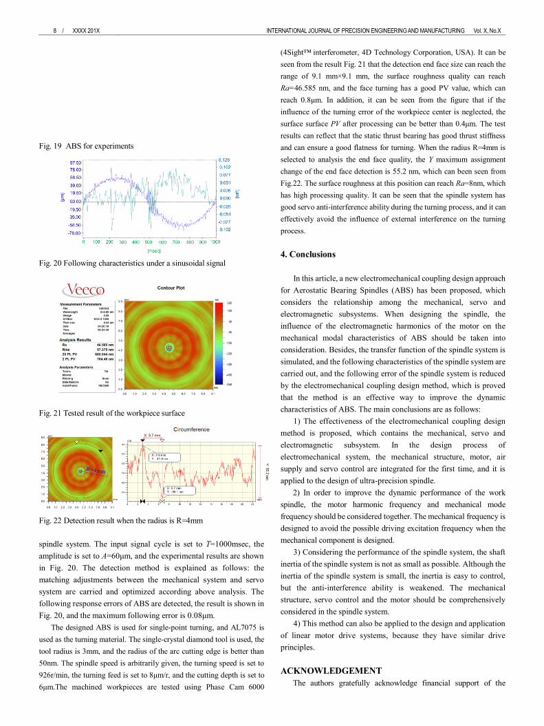
Fig. 19 ABS for experiments
Fig. 20 Following characteristics under a sinusoidal signal
Fig. 21 Tested result of the workpiece surface
Fig. 22 Detection result when the radius is R=4mm
spindle system. The input signal cycle is set to T=1000msec, the
amplitude is set to A=60μm, and the experimental results are shown
in Fig. 20. The detection method is explained as follows: the
matching adjustments between the mechanical system and servo
system are carried and optimized according above analysis. The
following response errors of ABS are detected, the result is shown in
Fig. 20, and the maximum following error is 0.08μm.
The designed ABS is used for single-point turning, and AL7075 is
used as the turning material. The single-crystal diamond tool is used, the
tool radius is 3mm, and the radius of the arc cutting edge is better than
50nm. The spindle speed is arbitrarily given, the turning speed is set to
926r/min, the turning feed is set to 8μm/r, and the cutting depth is set to
6μm.The machined workpieces are tested using Phase Cam 6000
(4Sight™ interferometer, 4D Technology Corporation, USA). It can be
seen from the result Fig. 21 that the detection end face size can reach the
range of 9.1 mm×9.1 mm, the surface roughness quality can reach
Ra=46.585 nm, and the face turning has a good PV value, which can
reach 0.8μm. In addition, it can be seen from the figure that if the
influence of the turning error of the workpiece center is neglected, the
surface surface PV after processing can be better than 0.4μm. The test
results can reflect that the static thrust bearing has good thrust stiffness
and can ensure a good flatness for turning. When the radius R=4mm is
selected to analysis the end face quality, the Y maximum assignment
change of the end face detection is 55.2 nm, which can been seen from
Fig.22. The surface roughness at this position can reach Ra=8nm, which
has high processing quality. It can be seen that the spindle system has
good servo anti-interference ability during the turning process, and it can
effectively avoid the influence of external interference on the turning
process.
4. Conclusions
In this article, a new electromechanical coupling design approach
for Aerostatic Bearing Spindles (ABS) has been proposed, which
considers the relationship among the mechanical, servo and
electromagnetic subsystems. When designing the spindle, the
influence of the electromagnetic harmonics of the motor on the
mechanical modal characteristics of ABS should be taken into
consideration. Besides, the transfer function of the spindle system is
simulated, and the following characteristics of the spindle system are
carried out, and the following error of the spindle system is reduced
by the electromechanical coupling design method, which is proved
that the method is an effective way to improve the dynamic
characteristics of ABS. The main conclusions are as follows:
1) The effectiveness of the electromechanical coupling design
method is proposed, which contains the mechanical, servo and
electromagnetic subsystem. In the design process of
electromechanical system, the mechanical structure, motor, air
supply and servo control are integrated for the first time, and it is
applied to the design of ultra-precision spindle.
2) In order to improve the dynamic performance of the work
spindle, the motor harmonic frequency and mechanical mode
frequency should be considered together. The mechanical frequency is
designed to avoid the possible driving excitation frequency when the
mechanical component is designed.
3) Considering the performance of the spindle system, the shaft
inertia of the spindle system is not as small as possible. Although the
inertia of the spindle system is small, the inertia is easy to control,
but the anti-interference ability is weakened. The mechanical
structure, servo control and the motor should be comprehensively
considered in the spindle system.
4) This method can also be applied to the design and application
of linear motor drive systems, because they have similar drive
principles.
ACKNOWLEDGEMENT
The authors gratefully acknowledge financial support of the

INTERNATIONAL JOURNAL OF PRECISION ENGINEERING AND MANUFACTURING Vol. X, No. X, pp. X-XX XXXX 201X / 9
International Science & Technology Cooperation Program of China
(No. 2015DFA70630), the National Natural Science Foundation of
China (Grant No.51505107), and China Scholarship Council.
REFERENCES
1. Chen, G. D., Sun, Y. Z., Zhang, F. H., An, C.H., Chen, W. Q., and
Su, H., "Influence of ultra-precision flycutting spindle error on
surface frequency domain error formation," The International
Journal of Advanced Manufacturing Technology, Vol.88, pp.1-9,
2017.
2. Liu, J.F., and Chen, X.A., "Dynamic design for motorized
spindles based on an integrated model," The International Journal
of Advanced Manufacturing Technology, Vol.71, pp.1961-1974,
2014.
3. Abele, E., Altintas, Y., and Brecher. C., "Machine tool spindle
units," CIRP Annals - Manufacturing Technology, Vol. 59, No.2,
pp.781-802, 2010.
4. Lin, C. W., Tu, J. F., and Kamman, J., "An integrated thermo-
mechanical-dynamic model to characterize motorized machine
tool spindles during very high speed rotation." International
Journal of Machine Tools & Manufacture, Vol.43, No.10, pp.1035-
1050, 2003.
5. Jiang S, Zheng S. "Dynamic Design Of A High-Speed Motorized
Spindle-Bearing System," Journal of Mechanical Design, Vol.132,
No.3, pp.1-5, 2010.
6. Chen, G.D., Sun, Y., An, C.H., Zhang, F.H., Sun, Z.J., and Chen,
W.Q., "Measurement and analysis for frequency domain error of
ultra-precision spindle in a flycutting machine tool," Proceedings
of the Institution of Mechanical Engineers Part B Journal of
Engineering Manufacture, Vol.232, No.9, pp.1501–1507, 2018.
7. Li. H., Shin. Y. C., "Analysis of bearing configuration effects on
high speed spindles using an integrated dynamic thermo-
mechanical spindle model," International Journal of Machine
Tools & Manufacture, Vol.44, No.4, pp.347-364, 2004.
8. Gao, S., Cheng, K., Chen, S., Ding, H., and Fu, H.Y.,
"Computational design and analysis of aerostatic journal
bearings with application to ultra-high speed spindles,"
ARCHIVE Proceedings of the Institution of Mechanical
Engineers Part C Journal of Mechanical Engineering Science,
Vol.231, No.7, pp.1205-1220, 2016.
9. Cui, H., Wang, Y., Yue, X., Huang, M., and Wang, W., "Effects of
manufacturing errors on the static characteristics of aerostatic
journal bearings with porous restrictor," Tribology International,
Vol.115, pp:246-260, 2017.
10. Chen, X., Yuan, S. H., and Peng, Z.X., “Nonlinear vibration for
PMSM used in HEV considering mechanical and magnetic
coupling effects,” Nonlinear Dynam, Vol. 80, pp. 541-552, 2015.
11. Huo, D. H., Cheng. K., and Wardle, F., "Design of a five-axis ultra-
precision micro-milling machine—UltraMill. Part 2: integrated
dynamic modelling, design optimization and
analysis," International Journal of Advanced Manufacturing
Technology, Vol. 47, pp.879-890, 2010.
12. Zhong, G.L., Shao, Z.Z., Deng, H., and Ren, J.L., "Precise Position
Synchronous Control for Multi-Axis Servo Systems," IEEE
Transactions on Industrial Electronics, Vol.64, No.5, pp.3707-3717,
2017.
13. Jeong, S. K., and You, S. S., "Precise position synchronous control
of multi-axis servo system," Mechatronics, Vol.18, No.3, pp.129-
140, 2008.
14. Chen, C. S., and Chen, L. Y., "Robust Cross-Coupling
Synchronous Control by Shaping Position Commands in
Multiaxes System." IEEE Transactions on Industrial Electronics .
Vol.59, No.12, pp.4761-4773, 2012.
15. Kim, J. H., and Lee, S. K., "Micro-patterning technique using a
rotating cutting tool controlled by an electromagnetic
actuator," International Journal of Machine Tools & Manufacture,
Vol. 101, pp.52-64, 2016.
16. Yang, S. M., and Lin, K. W., "Automatic Control Loop Tuning for
Permanent-Magnet AC Servo Motor Drives," IEEE Transactions
on Industrial Electronics, Vol. 63, No.3, pp.1499-1506, 2016.
17. Xu, L., and Li, H., "Resonant Responses for an Electromechanical
Integrated Harmonic Piezodrive System," Journal of Bacteriology,
Vol.169, No.5, pp.2245-50, 2012.
18. Liang, Y.C., Chen, W.Q., Sun, Y.Z., Luo, X.C., and Liu, H.T., "A
mechanical structure-based design method and its implementation
on a fly-cutting machine tool design," International Journal of
Advanced Manufacturing Technology, Vol.70, pp:1915-1921,
2014.
19. Cui, H.L., Wang, Y., Yang, H., Zhou, L., Li, H., Wang, W., and
Zhao, C.J., "Numerical analysis and experimental research on the
angular stiffness of aerostatic bearings," Tribology International,
Vol.120, pp.166-178, 2018.
20. Gao, S., Cheng, K., Chen, S., Ding, H., and Fu, H.Y., "CFD
based investigation on influence of orifice chamber shapes for
the design of aerostatic thrust bearings at ultra-high speed
spindles," Tribology International, Vol.92, pp.211-221,2015.
21. Chen, C.,Kang, Y.,and Huang, C., "The influences of capillary
restriction and journal eccentricity on the stability of the rigid rotor‐
hybrid bearing system," Tribology International, Vol.37, No.1,
pp.227-234, 2004.
22. Guan, C.L., Dai, Y.F., Xie, X.H., and Yin, Z.Q., "Investigation on
feedback control of linear motors in ultraprecision-machine feed-
drive systems," Journal of Vacuum Science & Technology B
Microelectronics & Nanometer Structures Processing
Measurement & Phenomena, Vol. 27, No.3, pp.1351-1354, 2009.
23. Yang, X.J., Lu, D., Liu, H., and Zhao, W.H., "Integrated modeling
and analysis of the multiple electromechanical couplings for the
direct driven feed system in machine tools." Mechanical Systems
& Signal Processing, Vol.106, pp.140-157, 2018.
24. Yang, X.J., Lu, D., and Zhao, W.H., "Decoupling and effects of the
mechanical vibration on the dynamic precision for the direct-
driven machine tool." International Journal of Advanced
Manufacturing Technology, Vol.95, pp.3243-3258, 2018.
25. Shi, H., Niguchi. N., and Hirata, K., "Characteristic Analysis of
Surface Permanent Magnet Vernier Motor according to Pole Ratio

10 / XXXX 201X INTERNATIONAL JOURNAL OF PRECISION ENGINEERING AND MANUFACTURING Vol. X, No.X
and Winding Pole Number." IEEE Transactions on Magnetics,
Vol.53, No.11, 821104, 2017.
26. Lee, Y., Shin, D., Kim, W., and Chung, C.C., "Proximate In-Phase
Current Estimator to Reduce Torque Ripple in Permanent-Magnet
Stepping Motor." IEEE Transactions on Industrial Electronics,
Vol. 63, No.3, pp.1707-1716, 2016.
27. Xia, C.L, Ji, B., and Yan, Y., "Smooth Speed Control for Low-
Speed High-Torque Permanent-Magnet Synchronous Motor Using
Proportional–Integral–Resonant Controller," IEEE Transactions
on Industrial Electronics, Vol.62, No.4, pp.2123-2134, 2015.
Related Documents