H I LL IN I S UNIVERSITY OF ILLINOIS AT URBANA-CHAMPAIGN PRODUCTION NOTE University of Illinois at Urbana-Champaign Library Large-scale Digitization Project, 2007.

Welcome message from author
This document is posted to help you gain knowledge. Please leave a comment to let me know what you think about it! Share it to your friends and learn new things together.
Transcript

HI LL IN I SUNIVERSITY OF ILLINOIS AT URBANA-CHAMPAIGN
PRODUCTION NOTE
University of Illinois atUrbana-Champaign Library
Large-scale Digitization Project, 2007.


UNIVERSITY OF IILINOIS
ENGINEERING EXPERIMENT STATION
BULLETIN No. 124 OCT., 1921
AN INVESTIGATION OF THE FATIGUE OF METALS
A REPORT OF THE INVESTIGATION
CONDUCTED BY
THE ENGINEERING EXPERIMENT STATIONUNIVERSITY OF ILLINOIS
IN COOPERATION WITH
THE NATIONAL RESEARCH COUNCILTHE ENGINEERING FOUNDATION
THE GENERAL ELECTRIC COMPANY
BY
H. F. MOORERESEARCH PROFESSOR OF ENGINEERING MATERIALS
IN CHARGE, INVESTIGATION OF THE FATIGUE OF METALS
AND
J. B. KOMMERSRESEARCH ASSOCIATE PROFESSOR OF ENGINEERING MATERIALS
ENGINEER OF TESTS, INVESTIGATION OF THE FATIGUE OF METALS
ENGINEERING EXPERIMENT STATIONPUBLIbHED BY THE UNIVERSITY OF ILLINOIS, URBANA

CONTENTS
PAGE
I. INTRODUCTION . . . . . . * * * * * * * * 9
1. Inception of the Investigation . . . . . . . 9
2. Personnel of the Advisory Committee of the Division
of Engineering of the National ResearchCouncil . . . . . . . . . . . 10
3. Outline of Investigation . . . . . . . . 11
4. Organization of Test Party . . . . . . . 12
5. Acknowledgments . . . . . . . . . . 12
II. MATERIALS, TESTS, TESTING APPARATUS, AND TEST SPECI-
MENS . ... . * . . . ....... **14
6. Materials . . . . . . . . . . . . .. 14
7. Tests . . . . . . . . . . . . . . 19
8. Testing Machines and Apparatus . . . . . . 20
9. Test Specimens . . . . . . . . . . . 43
10. Finish of. Specimens . . . . . . . . . 48
11. Numbering of Specimens . . . . . . . . 48
12. Procedure in Tests-Accuracy and Sensitiveness . 49
III. TEST
13.
DATA AND RESULTS . . . . . .
Summary of Test Data and Results .
. . 54
54
IV. DISCUSSION OF RESULTS . . . . . . . . . . . 90
14. Endurance Limit . . . . . . . . . . 90
15. Some Factors Influencing Endurance Limit . . 93
16. Relation of Static Strength to Endurance Limit . 9517. Correlation of Results of Hardness Tests and of
Impact Tests with Results of Reversed-StressTests . . . . . . . . . . . . 100
18. Accelerated Methods of Determining EnduranceLimit . . . . . . . . . . . . 102

CONTENTS (CONTINUED)
19. Effect of Cold Work on Fatigue Strength . . 104
20. Effect of Shape of Specimen on Endurance . . 105
21. Effect of Surface Finish . . . . . . . . 108
22. Effect of Overstress . . . . . . . . . 112
23. Theories of Nature of Fatigue of Metals . . . 114
V. "RISE OF TEMPERATURE" METHOD OF DETERMINING EN-
DURANCE LIMIT, BY W. J. PUTNAM AND J. W.
HARSCH . . . . . . . . . . . . . 119
24. Thermal Phenomena in Metals Under Stress . . 119
25. Apparatus . . ... ......... 120
26. Materials .. . . . . . . . . . . . 123
27. Tests . .. . . . . . . . . .. . . 123
28. Results and Discussion . . . . . . . . . 124
VI. SUBJECTS FOR FURTHER INVESTIGATION . . . . . . 128
29. Effect of Repetition of Stress Not Reversed . . 128
30. Tests on Other Ferrous Metals . . . . . . 128
31. Tests on Non-Ferrous Metals . . . . . . . 128
32. Effect of Heat Treatment . . . . . . . . 129
33. Direct Tension-Compression Tests . . . . . 129
34. Strength Under Reversed Shearing Stress . . . 129
35. Study of Mechanism of Fatigue Failure . . 130
36. Effect of Repeated Understressing . . .. . 130
37. Strength of Cast Metal Under Repeated Stress . 130
38. Repair by Heat Treatment of Structural Damage
Due to Repeated Stress . . . . . . . 131
VII. CONCLUSIONS . . . . . . . . . . . . . 132
39. Summary of Conclusions . . . . . . . . 132
APPENDIX A ................ 135
Comparison of Endurance Tests Beyond Yield Point
With Endurance Tests Within Yield Point . . . 135
CONTENTS (CONTINUED) 5
APPENDIX B . . . . . . . . . . . . .. .. ... 141
Fatigue Phenomena in Metals . . . . . . . . 141
APPENDIX C . . . . . . . . . . . . . . . . 160
Glossary of Technical Terms . . . . . . . . 160
APPENDIX D . . . . . . . . . . . . . . . . 168
Bibliography . . . . . . . . . . . . . 168
LIST OF FIGURES
NO. PAGE
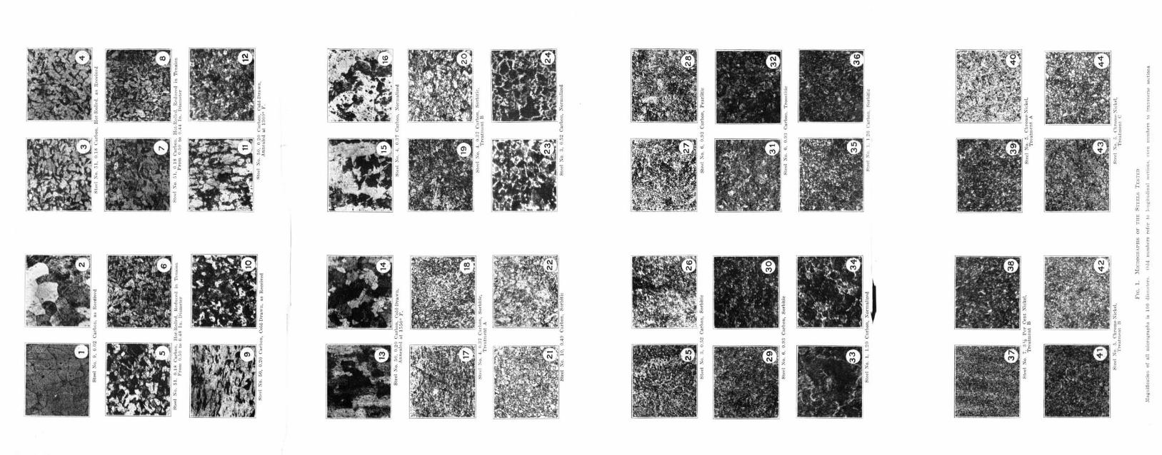
1. Micrographs of the Steels Tested . . . . ....... . . . 15
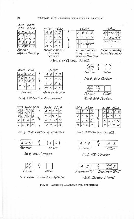
2. Marking Diagrams for Specimens ... . . . . . . . 18
3. Rotating-Beam Testing Machine (Farmer) . . . . . . . . . 21
4. Diagram of Rotating-Beam Testing Machine (Farmer) . . . . . 23
5. Rotating-Beam Testing Machine (Wisconsin) . . . . . . . . 25
6. Diagram of Rotating-Beam Testing Machine (Wisconsin) . . . . 27
7. Upton-Lewis Reversed-Bending Testing Machine . . . . . . . 29
8. Diagram of Upton-Lewis Reversed-Bending Testing Machine . . . 28
9. Olsen-Foster Reversed-Torsion Testing Machine . . . . . . . 30
10. Diagram of Olsen-Foster Reversed-Torsion Testing Machine . . . . 28
11. Charpy Single-Blow Impact Testing Machine . . . . . . . . 33
12. Tension Test Attachment for Charpy Impact Testing Machine . . . 35
13. Repeated-Impact Testing Machine ... . . . . . . . 37
14. Diagram of Repeated-Impact Testing. Machine . . . . . . . . 36
15. Apparatus for Magnetic Tests . . . . . . . . . 38
16. Detrusion Indicator for Torsion Tests . . . . . . . . .. 40
17. Heat- Treating Equipment . . . . . . . . . . 41
18. Test Specimens . . . .. . . . . . 44
19. Test Specimens .. . . . * * . . . . . . . 45
20. Variation of Stress Along Farmer-Type Test Specimen . . . . . 46
21. Representative Stress-Strain Diagrams for Tension Tests . . . . . 51
22. Representative Stress-Strain Diagrams for Compression Tests . . . 62
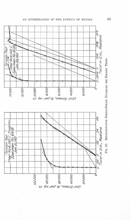
23. Representative Stress-Strain Diagrams for Torsion Tests . . . . . 63
24. S-N Diagrams for 0.93 Carbon Steel and for 1.20 Carbon Steel, Rotat-
ing-Beam Tests . . . . . . . . . . . . 64
25. S-N Diagrams for Chrome-Nickel Steel and for 0.37 Carbon Steel, Rotat-
ing-Beam Tests . . . . . . . ............... . 65
26. S-N Diagrams for 0.52 Carbon Steel, 0.49 Carbon Steel, 0.02 Carbon
Steel, and 3.5 Nickel Steel, Rotating-Beam Tests . . . . . . 66
27. S-N Diagrams for Hot-Rolled Steel and for Cold-Drawn Steel, Rotating-
Beam Tests . . . . . . . . . . ....... . 67
28. S-N Diagrams Showing Effect of Shape of Specimen, Rotating-Beam
Tests . . . . .. . . .. . . . . . . . . . . . 68
29. S-N Diagrams Showing Effect of Surface Finish, Rotating-Beam Tests 69
6
LIST OF FIGURES (CONTINUED)
30. S-N Diagrams Showing Effect of Overstress, 0.49 Carbon Steel, Rotating-Beam Tests ................. . 70
31. S-N Diagrams Showing Effect of Overstress, 1.20 Carbon Steel, Rotating-Beam Tests . . . . . . . . . . . . . . . . .. 71
32. S-N Diagrams, Upton-Lewis Tests, 0.93 Carbon Steel, 1.20 Carbon Steel,0.49 Carbon Steel, and 0.02 Carbon Steel . . . . . . . . 72
33. S-N Diagrams, Upton-Lewis Tests, 0.52 Carbon Steel, 0.37 Carbon Steel,and Chrome-Nickel Steel; Tests on Wisconsin Machine, Chrome-Nickel Steel . . . . . . . . . . . . . . . . .. 73
34. S-N Diagrams, Olsen-Foster Tests, 0.93 Carbon Steel, 0.02 Carbon Steel,and 0.49 Carbon Steel . . . . . . . . . . ... . 74
35. S-N Diagrams, Olsen-Foster Tests, 0.37 Carbon Steel and Chrome-NickelSteel . . . . . . . . . . . . . . . ... . 75
36. Various Methods of Plotting S-N Diagrams . . . . . . . . . 91
37. Comparison of Endurance Limits With Temperature Endurance Limits,Proportional Limits, and Ultimate Tensile Strengths . . . . . 96
38. Comparison of Endurance Limits With Brinell Hardness, Charpy Impact-Bending Values, Charpy Impact-Tension Values, and Repeated-Im-pact Values . . . . . . . . . . . . . . . . 101
39. Specimens for Study of Effect of Shape on Endurance Limit . . . 10740. Micrographs of Surface Finish ... . . . . . . . .. 109
41. Micrograph of Surface of Rouge-Finished Specimen . . . . . . 11042. Machine for "Rise of Temperature" Tests . . . . . . . .. 12143. Representative Diagrams for "Rise of Temperature" Tests . . . . 12544. S-N and D-N Diagrams for Tests on Wisconsin Rotating-Beam Testing
Machine . . . . . . . . . . . . . . . . .. . 13945. Diagrams of Typical Repeated-Stress Testing Machines . . . . . 14546. Micrograph Showing Slip Lines in Iron . . . . . . . . . . 147
LIST OF TABLES
NO. PAGE
1. Chemical Analyses of Steels Tested . . . . . . . . . . . 14
2. Heat Treatments of Steels Tested ... . . . . . . . 17
3. Results of Tension Tests .... . . . . . . . . 55-56
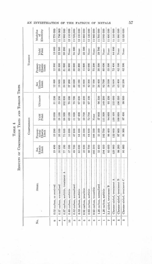
4. Results of Compression Tests and Torsion Tests . . . . . . . 57
5. Results of Hardness Tests, Impact Tests, Francke Tests, and Reversed-Stress Tests . . . . . . . . . . . . . . . 58-59
6. Representative Summary Sheet; Tests of Chrome-Nickel Steel, Treat-ment A ................. 60-61
7. S-N Results for Reversed-Stress Tests . . . . . . . . . 76-898. Comparison of Endurance Limit Found by Rotating-Beam Tests With
That Found by "'Rise of Temperature" Tests . . . . . . 124
9. Chemical Analyses of Steels for Special Series of Tests in the WisconsinRotating-Beam Testing Machine . . . . . . . . . . . 136
10. Results of Tension Tests of Steels for Special Series of Tests in theWisconsin Rotating-Beam Testing Machine . . . . . . . 137
11. Comparison of Computed Values and Actual Values of Stress for Spe-cial Series of Tests in the Wisconsin Rotating-Beam Testing Machine 140
12. Approximate Service Required of Various Members of Structures andMachines Subjected to Repeated Stress . . . . . . . . . 143
AN INVESTIGATION OF THE FATIGUE OF METALS
I. INTRODUCTION
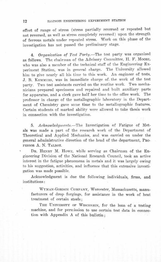
1. Inception of the Investigation.-For three-quarters of a cen-
tury the problem of the strength of metals under stresses repeated
many times has engaged the attention of engineers. It has been
recognized that loads which cause no apparent damage when applied
a few times to a machine or structural part may cause failure if
applied many times. Various investigations of the phenomenon of
failure under repeated stress* have been made and the name "fatigue
of metals" has been given to it. The earliest extensive investigation,
and the best known, is that of W6hler, whose results were published
in 1870.During the world war the question of strength of airplane parts
under repeated stress became of prime importance. A special phase
of this problem was a study of the strength of parts made of cold-
drawn steel, and a short series of experiments was made in the labora-
tories of the University of Illinois at the request of the National
Research Council.t This problem and other problems of material
under repeated stress, notably repeated stresses in welded ships,
brought the whole subject of fatigue phenomena of metals to the
attention of the National Research Council. The result was the
organization of an investigation by the cooperation of the National
Research Council Division of Engineering, Engineering Foundation,
and the Engineering Experiment Station of the University of Illi-
nois. Later the General Electric Company joined this group.
The National Research Council furnished an Advisory Commit-
tee to formulate general policies for the investigation. The Engineer-
ing Experiment Station provided a laboratory, the time of one mem-
ber of its staff, and the use of much apparatus. A previous progress
report of this investigation gave a general summary of the knowledge
of fatigue phenomena of metals current at the time of the beginning
of the investigation. This was published in "Mechanical Engineer-
* See Appendix C, which gives a glossary of technical terms used in this bulletin.
tMoore and Putnam, Am. Inst. of Mining and Metall. Engrs., Bul. 146, p. 401, Feb.,
1919,

ILLINOIS ENGINEERING EXPERIMENT STATION
ing" (the organ of the American Society of Mechanical Engineers),for September, 1919, and is reprinted in substance as Appendix B of
this bulletin.*The investigation was financed, first, by Engineering Foundation
from the fund given by Mr. Ambrose Swasey of Cleveland, Ohio.This grant was sufficient to permit the organization of a test party,the purchase of many pieces of apparatus, the preparation of a largenumber of specimens, and the maintenance of the laboratory for aterm of two years. In 1920 the General Electric Company con-tributed an equal sum for investigations along certain lines of specialinterest to them, without any restrictions as to the free publicationof the results. This contribution made possible the enlargement of thetest party and the purchase of more equipment. The lines of in-vestigation desired by the General Electric Company follow so closelythe lines of the original investigation that, in compiling this report,data and results have been taken from both parts, but mainly fromthe original investigation financed by Engineering Foundation, as,owing to the fact that this part of the investigation had been in pro-gress for a longer time, more material was available from this source.
2. Personnel of the Advisory Committee of the Division of En-gineering of the National Research Council.-The personnel of theAdvisory Committee is given below:
0. H. BASQUIN, Professor of Applied Mechanics, North-western University;
F. P. GILLIGAN, Secretary-Treasurer, Henry Souther En-gineering Company;
HENRY M.' HOWE, Metallurgist, Bedford Hills, New York;ZAY JEFFRIES, Director of the Cleveland Section of the
Research Bureau, Aluminum Company of America;T. R. LAWSON, Professor of Rational and Applied Mechanics,
Rensselaer Polytechnic Institute;J. A. MATHEWS, President, Crucible Steel Company of
America;
*For a more detailed account of previous investigations of the strength of materialsunder repeated stress see:
Unwin, W. C. "The Testing of the Materials of Construction," Chap. XVI, 1910.Withey and Aston, "Johnson's Materials of Construction," Fifth Edition, Chap. XXVIII.

AN INVESTIGATION OF THE FATIGUE OF METALS
JOHN H. NELSON, Chief Metallurgist, Wyman-Gordon Com-
pany;W. E. RUDER, Metallurgist, Research Laboratory, General
Electric Company;H. L. WHITTEMORE, Chief of Section of General Physical
Testing, U. S. Bureau of Standards;LEONARD WALDO, Consulting Engineer, New York City;
H. F. MOORE, Research Professor of Engineering Materials,
University of Illinois, Chairman.
In connection with the work of the Advisory Committee there
have been organized two sub-committees: first, a sub-committee on
Heat Treatment of Specimens, J. H. NELSON, Chairman (resigned
October 22, 1920), W. E. RUDER, Chairman (since October 30, 1920),and F. P. GILLIGAN; and second, a sub-committee on Statistics, T. R.
LAWSON, Chairman, LEONARD WALDO, and H. L. WHITTEMORE.
3. Outline of Investigation.-At a meeting held February 19,1920, the Advisory Committee planned reconnaissance tests of ma-
terials well scattered over the field of ferrous metals, in most cases
studying two or more distinct heat treatments for each metal. It
was decided not to enter the field of non-ferrous metals at this time.For each heat treatment of each steel tested it was planned to
make a series of tests of specimens under reversed bending stress,using various stresses, until an "endurance" of 100 000 000 reversals,was reached; to make corresponding static tests in tension, compres-sion, and shear (torsion) ; and to make various auxiliary tests, in-cluding hardness tests and impact tests.
It was planned to use magnetic analysis for examining the homo-geneity of the material tested, and to study various accelerated testsfor resistance to repeated stress in order to determine their reliability.
The main purpose of this first stage of the investigation was todetermine whether for ferrous metals there exists any clearly definedrelation between the static properties (elastic limit, yield point, ulti-mate tensile strength, elongation, reduction of area, hardness, etc.)and ability to resist reversed stress.
When later the General Electric Company became a party tothe investigation there was added to this program the study of the
ILLINOIS ENGINEERING EXPERIMENT STATION
effect of range of stress (stress partially reversed or repeated but
not reversed, as well as stress completely reversed) upon the strength
of ferrous metals under repeated stress. Work on this phase of the
investigation has not passed the preliminary stage.
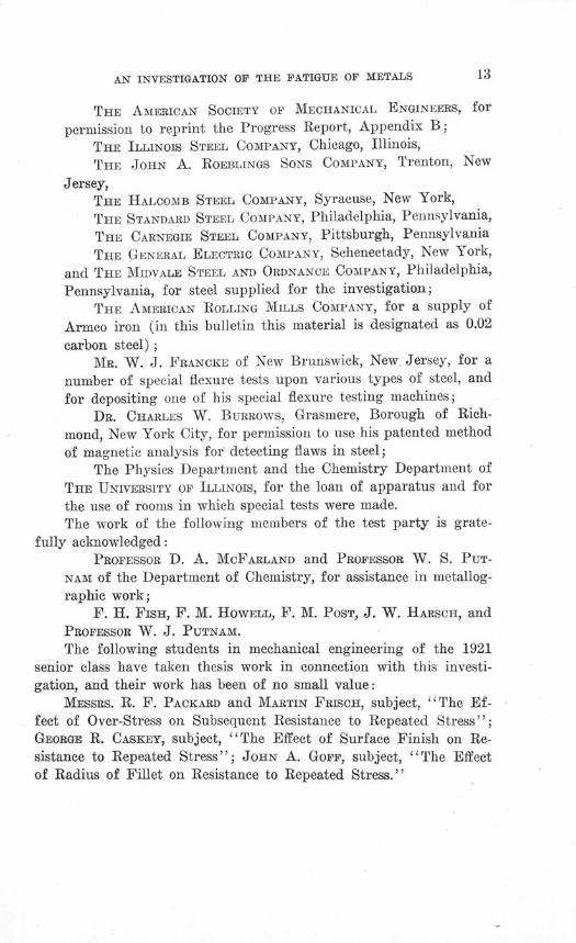
4. Organization of Test Party.-The test party was organized
as follows. The. chairman of the Advisory Committee, II. F. MOORE,
who was also a member of the technical staff of the Engineering Ex-
periment Station, was in general charge. The University allowed
him to give nearly all his time to this work. An engineer of tests,J. B. KOMMERS, was in immediate charge of. the work of the test
party. Two test assistants carried on the routine work. Two mecha-
nicians prepared specimens and repaired and built auxiliary partsfor apparatus, and a clerk gave half her time to the office work. Theprofessor in charge of the metallographic laboratory in the Depart-ment of Chemistry gave some time to the metallographic features.Certain students of marked ability were allowed to take thesis workin connection with the investigation.
5. Acknowledgments.-The Investigation of Fatigue of Met-als was made a part of the research work of the Department ofTheoretical and Applied Mechanics, and was carried on under thegeneral administrative direction of the head of the department, PRO-FESSOR A. N. TALBOT.
DR. HENRY M. HOWE, while serving as Chairman of the En-gineering Division of the National Research Council, took an activeinterest in the fatigue phenomena in metals and it was largely owingto his suggestion, activities, and influence that this extensive investi-gation was made possible.
Acknowledgment is due the following individuals, firms, andinstitutions:
WYMAN-GORDON COMPANY, Worcester, Massachusetts, manu-facturers of drop forgings, for assistance in the work of heattreatment of certain steels;
THE UNIVERSITY OF WISCONSIN, for the loan of a testingmachine, and for permission to use certain test data in connec-tion with Appendix A of this bulletin;
AN INVESTIGATION OF THE FATIGUE OF METALS
THE AMERICAN SOCIETY OF MECHANICAL ENGINEERS, for
permission to reprint the Progress Report, Appendix B;
THE ILLINOIS STEEL COMPANY, Chicago, Illinois,
THE JOHN A. ROEBLINGS SONS COMPANY, Trenton, New
Jersey,THE HALCOMB STEEL COMPANY, Syracuse, New York,THE STANDARD STEEL COMPANY, Philadelphia, Pennsylvania,THE CARNEGIE STEEL COMPANY, Pittsburgh, Pennsylvania
THE GENERAL ELECTRIC COMPANY, Schenectady, New York,
and THE MIDVALE STEEL AND ORDNANCE COMPANY, Philadelphia,
Pennsylvania, for steel supplied for the investigation;THE AMERICAN ROLLING MILLS COMPANY, for a supply of
Armco iron (in this bulletin this material is designated as 0.02
carbon steel);MR. W. J. FRANCKE of New Brunswick, New Jersey, for a
number of special flexure tests upon various types of steel, and
for depositing one of his special flexure testing machines;DR. CHARLES W. BURROWS, Grasmere, Borough of Rich-
mond, New York City, for permission to use his patented method
of magnetic analysis for detecting flaws in steel;The Physics Department and the Chemistry Department of
THE UNIVERSITY OF ILLINOIS, for the loan of apparatus and for
the use of rooms in which special tests were made.The work of the following members of the test party is grate-
fully acknowledged:PROFESSOR D. A. McFARLAND and PROFESSOR W. S. PUT-
NAM of the Department of Chemistry, for assistance in metallog-raphic work;
F. H. FISH, F. M. HOWELL, F. M. POST, J. W. HARSCH, and
PROFESSOR W. J. PUTNAM.
The following students in mechanical engineering of the 1921senior class have taken thesis work in connection with this investi-gation, and their work has been of no small value:
MESSRS. R. F. PACKARD and MARTIN FRISCH, subject, "The Ef-fect of Over-Stress on Subsequent Resistance to Repeated Stress";GEORGE R. CASKEY, subject, "The Effect of Surface Finish on Re-sistance to Repeated Stress"; JOHN A. GOFF, subject, "The Effectof Radius of Fillet on Resistance to Repeated Stress."
ILLINOIS ENGINEERING EXPERIMENT STATION
II. MATERIALS, TESTS, TESTING APPARATUS, AND TEST SPECIMENS
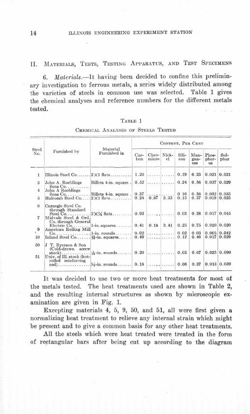
6. Materials.-It having been decided to confine this prelimin-
ary investigation to ferrous metals, a series widely distributed among
the varieties of steels in common use was selected. Table 1 gives
the chemical analyses and reference numbers for the different metals
tested.
TABLE 1
CHEMICAL ANALYSES OF STEELS TESTED
SteelNo.
Furnished by
1 !Illinois Steel Co.......
John A. RoeblingsSons Co..........
John A RoeblingsSons Co...........
Halcomb Steel Co.....
Carnegie Steel Co.through StandardSteel Co...........
Midvale Steel & Ord.Co. through GeneralElectric Co.........
American Rolling MillC o................
Inland Steel Co.......
J T. Ryerson & Son(Cold-drawn screwstock) .............
Univ. of Ill. stock (hot-rolled reinforcingrod) ......... .....
CONTENT, PER CENT
MaterialFurnished in Car- Chro- Nick- Sili- Man-
bon mium el con
2X 1 flats.......... 1.20 ...... ......
Billets 4-in. square . 0.52 .. .. . ...
Billets 4-in. square . 0.37 i. ...........2X1 flats.......... 0.24 0.87 3.33
2XH flats.........
1-in. squares. ......
1-in. rounds..... .1t-in. squares... .
A-in. rounds......
u-in. rounds.......
0.19
0.24
0.160.15
0.93 ............ 0.03
0.41 0.18 3.41 0.25
0.02 ............ 0.020.49 ....... ..... 0.12
0.20 ...... ...... 0.03
0.18 ........ 0.06
gan-ese
0.25
0.56
0.580.37
0.38
0.75
0.030.46
0.67
Phos- Sul-phor-
us
0.021
0.037
0.0320.019
0.017
0.020
0.0050.017
0.025
0 013
It was decided to use two or more heat treatments for most ofthe metals tested. The heat treatments used are shown in Table 2,and the resulting internal structures as shown by microscopic ex-amination are given in Fig. 1.
Excepting materials 4, 5, 9, 50, and 51, all were first given anormalizing heat treatment to relieve any internal strain which mightbe present and to give a common basis for any other heat treatments.
All the steels which were heat treated were treated in the formof rectangular bars after being cut up according to the diagram
phur
0.021
0.029
0.0350.025
0.045
0.020
0.0420.029
[ bon ii mium I e!
con
I
%., .4U*
II'
nz6
2jie
·e
a
l"ri
fio
t|.
C,r-;
;1
-1
a
o
cs-a


AN INVESTIGATION OF THE FATIGUE OF METALS
shown in Fig. 2, except the following: 0.37 carbon, sorbitic, treat-
iment A; 1.20 carbon, normalized; 1.20 carbon, sorbitic; and 0.93
carbon, troostitic. These steels were machined somewhat oversize,
then heat treated, and later finished to size.
TABLE 2
HEAT TREATMENTS OF STEELS TESTED
STEEL
1.20 carbon, normalized ... ....
sorbitic .............
0.52 carbon, normalized..........sorbitic.............
0.37 carbon, normalized ...........
sorbitic treatments. A and B.........
Chrome-nickel, treatment A.......
treatment B.......
treatment C .......
0.93 carbon, normalized ...........pearlitic....... ....
sorbitic ..............
troostitic ............
3.5 nickel, treatment B .........
0.02 carbon ................. . . . .
0.49 carbon, normalized .........sorbitic.............
Cold-drawn as received.annealed .............annealed............
0.18 carbon as received.cold stretched.......
cold stretched ........
cold bent............
HEAT TREATMENT
Heat to 1460° F.; hold 15 min.; cool in furnace (thisanneals the eteel so that it can be machined); thenheat to 15800 F.; hold 15 min.; cool in furnace withdoor open.
First anneal as above; then heat to 1470* F.; quench inoil; reheat to 8600 F.; hold 30 min.; cool in air.
Heat to 15500 F.; hold 15 rin.; cool in air.First normalize as above; then heat to 1450° F.; hold
15 min.; quench in water; reheat to 1200° F.; cool inair.
Heat to 1495° F.; hold 15 min.; cool in furnace with dooropen.
This steel was not first normalized. Heat to 1550° F.;hold 15 min.; quench in water; reheat to 10500 F.;cool in air.
Steel received annealed. Heat to 15250 F.; quench inoil; reheat to 7000 F.; quench in oil.
Steel received annealed. Heat to 15250 F.; hold for Yhour; quench in oil. Reheat to 14500 F.; quench in
oil. Reheat to 12000 F.; hold for 1 hour; cool infurnace.
Steel received annealed. Heat to 1525° F.; hold forY hour; quench in oil. Reheat to 1450° F.; quench inoil. Reheat to 1200* F.; hold for 1 hour; quench inwater.
Heat to 16000 F.; hold 15 min.; cool in air.First normalize as above, then heat to 1450° F.; hold 15
min.; cool in furnace.First normalize as above; then heat to 14500 F.; hold 15
min.; quench in oil; reheat to 1200° F.; bold 30 min.;cool in air.
First normalize as above; then heat to 14500 F.; hold15 min.; quench in oil; reheat to 8500 F.; hold 30 min.;cool in air.
Normalize by heating to 1525* F. and cooling in furnace;then heat to 1525° F.; quench in oil; reheat to 1210* F.;hold 2 hours; cool in furnace.
Tested as received.
Heat to 17000 F.; hold 20 min.; cool in air.First normalize as above; then heat to 14250 F.; Q.uench
in water; reheat to 1200° F.; cool in furnace.
Heat to 13000 F.; hold for 15 min.; cool in furnace.Heat to 15500 F.; hold for 15 min.; cool in furnace,
Reduced to diameter of 0.44 in.; then heat to 500° F.;cool in furnace.
Reduced to diameter of 0.48 in.; then heat to 5000 F.;cool in furnace.
Bent to an angle of 450 at the middle, straightened cold.
6
ILLINOIS ENGINEERING EXPERIMENT STATION
4A/3 4A324C/3 4CZ6 4C2/ 4C28 4 C33 4A/41A 8 COE ABC9 AB A6C9F h //J EFG EFGH / -WIF_ /NOL 1 / PKP RS T I K L.I
UVWXY /N NO P \ TFarmer Reverse Torsaon Impact Tens/on ReverseBend/ng/mpact Bend/ng Torsion Compression /mpact Bend/ng
Tension Reverse Bend7/g
A/a 4, 037 Carbon Sorb/'/c
4B/3 480 4B26AB CDE " A B C DF G H / i E F G H/(ILJ I O I
p 4 W2? s M N O P
Farmer Reverse Torsion
AO 4, 0.37 Carbon Norma/a'ed
3B13 3826 3C39 3839 3C26ABCDE A BCIDIEF GI HI/ /KL MN 0 F 0 H / J
P Q R S K I N
T 14 OP QR
No 3, 052 Carbon /Vorma//,ed
Farmer Other
/Va. 0.93 Carbon
Farmer Other
No. 7, Genera/ E/ectr/c 3% / I/:
0Farmer Other
Ao. 9, 0.02 Cardon
Farmer Other
No. /0, 0.49 Carbon
3A/3 3AZ6 3A439 3C/3ABCD ABCDE
SF GH FGHI/
SJN 0L K L MNR
0/N 0V OP&R
No. 3, 0.Z5 Carbon Sorb/tic
A" A B
Farmer 0ther
Na /, /20 Carbon
TrecZment % " Treament "9-C"
No.a 5, Chrome-/V'cke/
FIG. 2. MARKING DIAGRAMS FOR SPECIMENS

AN INVESTIGATION OF THE FATIGUE OF METALS
7. Tests.-Mechanical tests of metals may be divided into three
groups: first, "static" tests, usually made on the ordinary tension-
compression testing machine; second, repeated-stress tests, and third,
impact tests. Static tests include torsion and flexure tests and Brinell
hardness tests. Probably scleroscope hardness tests would also be
classified with static tests.
The results of static tests indicate the resistance of a metal to
the destructive action of a steady load or a load applied a few times.
Static tests yield significant results concerning the suitability of
material for buildings, tanks, and other structures, including most.
bridges.The results of repeated-stress tests indicate the resistance of a
metal to progressive failure under many repetitions of a given work-
ing load. Repeated-stress tests have not been thoroughly standard-
ized, but would seem to yield significant results concerning the suita-
bility of material for machine or structural parts which are to be
subjected to many repetitions of loading when there is little danger
of accidental heavy overload; springs, shafting, and car axles, for
example.The results of impact tests indicate the resisting power of ma-
terial against shattering under sudden heavy overload. Impact tests
would seem to yield significant results concerning the suitability of
material for machine or structural parts which may be occasionally
subjected to heavy overload, and which can still be used after some
permanent distortion has taken place. Impact-resisting power seems
to be a sort of insurance against complete collapse under sudden over-
load.In this connection it may be noted that the strength-indicating
results of static tests and the endurance limits given by repeated-
stress tests are measured in the same units-pounds per square inch;
the results of impact tests are measured in units of energy-foot-
pounds or inch-pounds. It may be further noted that the results.of
an impact test are comparable with a measurement of the area under
the complete stress-strain diagram for a static test, or, using a roughapproximation, the results of an impact test are comparable with the
product of ultimate strength and elongation given by a static test.The term toughness is sometimes used to indicate a combination ofthe static strength and the ductility, and the impact test may be said
ILLINOIS ENGINEERING EXPERIMENT STATION
to be the index of the toughness of a material. Again it may be noted
that the strength-indicating results of static tests, and the results of
repeated-stress tests indicate ability to withstand normal service con-
ditions, while the results of impact tests-and the results of static
tests which measure ductility-indicate ability to withstand occa-sional overload without complete shattering failure.
The principal series of tests in this investigation are the reversed-stress tests performed on the various materials. These tests are dis-cussed in further detail in Section 8. As the problem of determiningrelations existing between strength under repeated stress and strengthunder ordinary static tests was the primary problem of the investiga-tion, careful tests on ordinary testing machines formed another seriesof tests of prime importance. These tests included tension tests,compression tests, and torsion tests, the last named giving values forshearing strength.
In addition to the regular static tests, a limited number of spe-cial flexure tests were made, some in the laboratories of the Universityof Illinois and some at the laboratory of Mr. W. J. Francke of NewBrunswick, New Jersey.
Brinell and scleroscope hardness tests were made. Charpy im-pact tests were made, both on notched bars in bending and on tensionspecimens.
Magnetic tests for homogeneity were made on the bars used forrepeated-stress specimens for the rotating-beam machine before theywere reduced at the center.
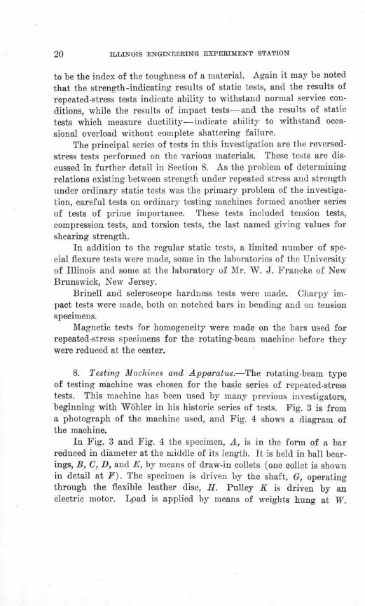
8. Testing Machines and Apparatus.-The rotating-beam typeof testing machine was chosen for the basic series of repeated-stresstests. This machine has been used by many previous investigators,beginning with W6hler in his historic series of tests. Fig. 3 is froma photograph of the machine used, and Fig. 4 shows a diagram ofthe machine.
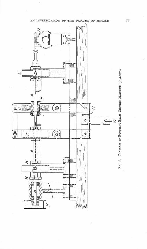
In Fig. 3 and Fig. 4 the specimen, A, is in the form of a barreduced in diameter at the middle of its length. It is held in ball bear-ings, B, C, D, and E, by means of draw-in collets (one collet is shownin detail at F). The specimen is driven by the shaft, G, operatingthrough the flexible leather disc, H. Pulley K is driven by anelectric motor. Lpad is applied by means of weights hung at W.
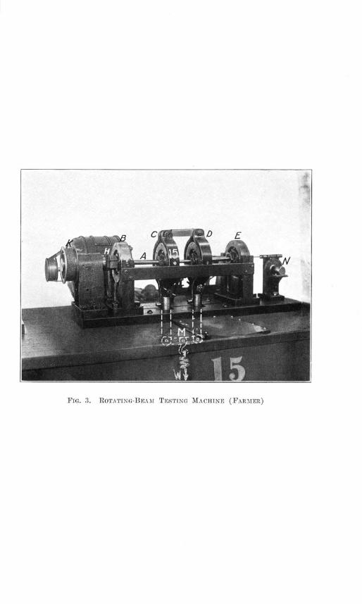
FIG. 3. ROTATING-BEAM TESTING MACHINE (FARMER)

AN INVESTIGATION OF THE FATIGUE OF METALS
Z7~
ILLINOIS ENGINEERING EXPERIMENT STATION
The weight, W, is distributed to the bearings, C and D, by meansof the equalizing bar, M. In the position shown the specimen is un-der flexure and the fibers along the top of the bar are in compressionwhile those on the under side of the bar are in tension. If the pulleyis given half a revolution the stress in the fibers is completely re-versed. The number of cycles of completely reversed stress givento the specimen is equal then to the number of revolutions of thepulley, K, which is indicated by means of the revolution counter, N.When the specimen breaks, the center bearings, C and D, drop to-gether with their housings and strike a trigger (not shown in Fig. 4)which releases the switch controlling the motor.
The machine produces a uniform bending moment on the speci-men between bearings C and D. This form of machine with twosymmetrical loads has been used by many investigators, the first, sofar as is known, being Professor Sondericker,* of the MassachusettsInstitute of Technology in 1892. The machine used in the presentinvestigation follows in its details quite closely that described byMr. F. M. Farmer before the American Society for Testing Materi-als at its 1919 meeting; hence, this machine is sometimes referredto as the Farmer machine.
Fig. 5 is from a photograph and Fig. 6 shows a diagram ofanother type of rotating-beam machine which was used for sometests. This machine had been designed by Professor Kommers atthe University of Wisconsin and is spoken of as the Wisconsin ma-chine. The specimen is rotated and is loaded as a cantilever beam.
The rotating-beam type of machine was chosen for making thebasic series of reversed-stress tests for a number of reasons. In thismachine the magnitude of the stresses can be computed with a highdegree of precision, and a prime requisite for the basic series oftests was that there should be little uncertainty as to the values ofthe stresses used. In its operation this machine is very free fromvibration. The slight vibration of the specimen was observed to bein synchronism with the rotation of the machine, and probably wascaused by the minute deviation from straightness of the axis of thespecimen. A slight vibration in synchronism with the rotation of the
* Sondericker, J. "A Description of Some Repeated-Stress Experiments," Tech. Quar.Boston, April, 1892.

FIG. 5. ROTATING-BEAM TESTING MACHINE (WISCONSIN)


AN INVESTIGATION OF THE FATIGUE OF METALS
specimen does not alter the range of stress to which the specimen is
subjected. The results obtained by this type of machine are notseriously affected by slight changes in speed. The writers made a
FIG. 6. DIAGRAM OF ROTATING-BEAM TESTING MACHINE (WISCONSIN)
somewhat careful search for test results at various speeds and foundconsiderable evidence* that speeds below 2000 revolutions per minutehave very little effect on the result of repeated-stress tests.
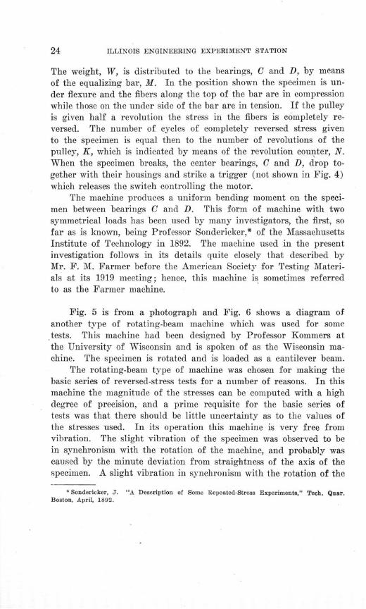
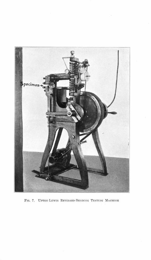
In another type of repeated-stress testing machine calibratedsprings are used to resist and to measure the bending moment orthe twisting moment applied to the specimen. Two machines ofthis type were used for a secondary series of reversed-stress tests.Fig. 7 is from a photograph of the Upton-Lewis machine used forflexural reversed-stress tests. Fig. 8 shows the scheme of the machinediagrammatically. In this machine the specimen is bent back andforth in one plane. The amount of deflection of the springs, andhence the magnitude of the bending moment applied to the specimen,is given by the width of the diagram drawn by the pencil point. Thenumber of cycles of bending stress is shown by the counter. Fig. 9
*Stanton and Pannell, Inst. Civ. Engrs. (British), CLXXXVIII, p. 814, 1911.Hopkinson, B. Proc. Royal Soc., A 86, January 31, 1912; Sci. Abs., 1912, No. 628.Roos, J. 0. Int. Assn. for Test. Materials, 1912, Art. V2B.Kommers, J. B. Int. Assn. for Test. Materials, 1912, Art. V4B.Stanton and Bairstow, Inst. Civ. Engrs. (British), CLXVI, p. 78, 1905-6.Upton and Lewis, American Machinist, October 17, 1912, p. 633.Eden, Rose, and Cunningham, Inst. Mech. Engrs. (British), 1911, Part 3-4, p. 839.

ILLINOIS ENGINEERING EXPERIMENT STATION
FIG. 8. DIAGRAM OF UPTON-LEWIS REVERSED-BENDING TESTING MACHINE
Front V/ E w RS/01e I/'ew
FIG. 10. DIAGRAM OF OLSEN-FOSTER REVERSED-TORSION TESTING MACHINE
pecirnen
FIG. 7. UPTON-LEWIS REVERSED-BENDING TESTING MACHINE
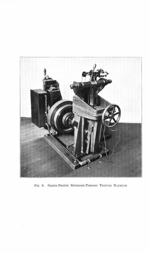
FIG. 9. OLSEN-FOSTER REVERSED-TORSION TESTING MACHINE
AN INVESTIGATION OF THE FATIGUE OF METALS
is from a photograph of the reversed-torsion machine, the Olsen-
Foster, while Fig. 10 gives a diagram of the same machine. The
specimen is subjected to an amount of twist in one direction from
the neutral position, and then to the same amount of twist in the
opposite direction. The scheme for measuring twisting moment and
number of cycles of twisting stress is similar to that used in the
Upton-Lewis machine.
These spring machines are, however, very much more expensive
than the rotating-beam machine, and, moreover, the error inherent
in spring calibration and the stresses caused by the inertia of recipro-
cating parts introduce some uncertainty as to the magnitude of some
of the stresses. A further objection to these machines is that they
cannot be run satisfactorily at speeds as high as 1500 revolutions per
minute.All the fatigue machines were provided with automatic devices
which stopped the machines when the specimen failed. These devices
made continuous operation of the machines possible.Repeated-stress testing machines, which depend upon the inertia
of reciprocating or rotating parts for producing stress, have some-
times been used. Such machines are markedly affected by varia-
tions in the speed, since the inertia effect is proportional to the square
of the speed. In tests which last for days at a time the power circuit
ordinarily available cannot be relied upon to give constant speed at
the motors, unless there is a very elaborate and expensive installationof speed-regulating devices. This consideration caused the rejectionof the inertia type of repeated-stress testing machine for this in-vestigation.
Testing machines employing alternating current magnets to pro-duce repeated stress were considered. These machines would be verymuch more expensive than the rotating-beam type of machine, and,moreover, slight variations in the frequency of the alternating cur-rent (such variations as would inevitably occur in the current sup-plied to the laboratory) might produce quite serious variations inthe force set up by the magnets.
There would seem to be some advantage in using machines whichproduce repetitions of direct tension or compression in a specimen.The only available machines producing such stress were of the alter-nating current magnet type or of the inertia type, and were so ex-
ILLINOIS ENGINEERING EXPERIMENT STATION
pensive that the funds of the investigation would not have permittedpurchasing a sufficient number of machines.
To sum up, the rotating-beam machine was chosen for the basicseries of tests primarily because it seemed to be a machine in which,within the yield point, definite stresses could be set up with a highdegree of precision, because it seemed least affected by slight varia-tions of frequency in the electric circuits supplying power, and be-cause it was the least expensive machine to construct.
As noted above, a careful study of the records of other testsseems to indicate that speed of testing has little effect on the resultsup to a speed of about 2000 revolutions per minute. The speedchosen for the Farmer machine was well within this limit, namely,1500 revolutions per minute. With the Upton-Lewis machine a speedof 300 revolutions per minute was used; with the Olsen-Foster ma-chine, a speed of 350 revolutions per minute was used, except forthe 0.93 carbon steel, troostitic, the 0.49 carbon steel, sorbitic, andthe chrome-nickel steel, treatment A, for which a speed of 260 revo-lutions per minute was used; with the Wisconsin machine a speedof 1200 revolutions per minute was used.
For the static compression tests and tension tests a 100 000-poundRiehle machine and a 10 000-pound Olsen machine were used. Forthe static torsion tests a Riehle 10000-inch-pound machine of thependulum type was used. In the last-named machine the twistingmoment exerted on the specimen is read from a micrometer dial gagewhich indicates a motion of 0.001 inch, and which is actuated bythe movement of the pendulum from its neutral position.
Fig. 11 is from a photograph of the Charpy impact machinewhich was used to make the impact-bending and impact-tension tests.In the single-blow impact testing machine, of which the Charpymachine is one type, a heavy pendulum is raised to a given anglefrom its normal position and then is allowed to fall against a speci-men. Rupturing the specimen (a short beam with a notch in it forthe impact-flexure test), the pendulum passes the neutral positionand rises to an angle indicated by a "maximum" finger. The dif-ference between angle of fall and angle of rise is a measure of theenergy absorbed in rupturing the specimen.* A centering device
* Dix, E. H., Jr. Proc. Am. Soc. for Test. Materials, Vol. XIX, Part II, p. 720, 1919.This is a detailed discussion of the single-blow impact testing machine.
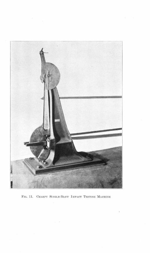
FIG. 11. CHARPY SINGLE-BLOW IMPACT TESTING MACHINE

AN INVESTIGATION OF THE FATIGUE OF METALS
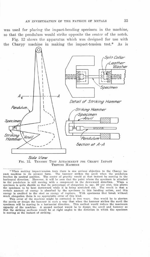
was used for placing the impact-bending specimen in the machine,so that the pendulum would strike opposite the center of the notch.
Fig. 12 shows the apparatus which was designed for use withthe Charpy machine in making the impact-tension test.* As is
Detail of Str/-ing Hammer
Sect/on at A -A
Side t/'ewFIG. 12. TENSION TEST ATTACHMENT FOR CHARPY IMPACT
TESTING MACHINE
*When making impact-tension tests there is one serious objection to the Charpy im-pact machine in its present form. The hammer strikes the anvil when the pendulumreaches its neutral position. The center of gravity would at that instant be moving in thehorizontal direction. However, it will be seen that the point where the specimen is attachedto the pendulum is still moving with a component in the downward direction. When aspecimen is quite ductile so that its percentage of elongation is, say, 30 per cent, this allowsthe specimen to be bent downward while it is being stretched out. The result is that acertain amount of energy is absorbed by the specimen in this bending action, and thisenergy is credited to the steel as energy of rupture. With specimens that break withoutmuch elongation there is no appreciable error of this kind.
This error of the machine might be corrected in two ways. One would be to shortenthe anvils or design the hammer in such a way that when the hammer strikes the anvil thespecimen will be moving in a horizontal direction. This method would reduce the maximumcapacity of the machine. A second method would be to design the anvil and hammer sothat the striking surfaces would be at right angles to the direction in which the specimenis moving at the instant of striking.
ILLINOIS ENGINEERING EXPERIMENT STATION
shown in the sketch, the specimen is provided with spherical seatsat the shoulders so that there may be slight adjustment of the speci-men when the hammer strikes the anvil.
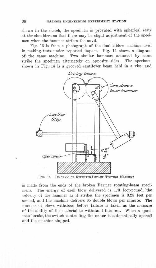
Fig. 13 is from a photograph of the double-blow machine usedin making tests under repeated impact. Fig. 14 shows a diagramof the same machine. Two similar hammers actuated by camsstrike the specimen alternately on opposite sides. The specimenshown in Fig. 14 is a grooved cantilever beam held in a vise, and
DrivIng Gears
FIG. 14. DIAGRAM OF REPEATED-IMPACT TESTING MACHINE
is made from the ends of the broken Farmer rotating-beam speci-mens. The energy of each blow delivered is 1/3 foot-pound, 'thevelocity of the hammer as it strikes the specimen is 3.25 feet persecond, and the machine delivers 65 double blows per minute. Thenumber of blows withstood before failure is taken as the measureof the ability of the material to withstand this test. When a speci-men breaks, the switch controlling the motor is automatically openedand the machine stopped.

/
FIG. 13. REPEATED-IMPACT TESTING MACHINE
Fia. 15. APPARATUS FOR MAGNETIC TESTS

AN INVESTIGATION OF THE FATIGUE OF METALS
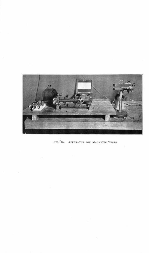
Fig. 15 shows a photograph of the magnetic testing machinewhich was used in making the test for homogeneity. This machinewas constructed at the University of Illinois. It follows closely de-signs suggested by Dr. C. W. Burrows of New York, and by R. L.Sanford of the United States Bureau of Standards. The steel coreat A was wound with wire which carried a current of 7.5 amperes.The magnetic circuit was completed through the specimen, B, andthe uprights, C. At D is a screw threading through the small car-riage at E. When the pulley, F, at the end of the screw is drivenfrom the motor, M, the carriage, E, is moved over the specimen ata uniform speed. The carriage surrounds the specimen and uponthe carriage are two coils, differentially wound, in which a smallelectromotive force is induced when the carriage moves through themagnetic lines of force. From the two coils terminals extend to astring galvanometer, G. If the specimen, B, is homogeneous instructure and free from both irregularities of form and internalstresses the electromotive force in one coil neutralizes that in theother and there is no deflection of the galvanometer. If there is anon-homogeneous section of the specimen, then, as each coil in turnpasses over that section, the balance of the coils is disturbed anddeflection of the galvanometer results.* Experiments showed thatthis device was particularly sensitive in pointing out places in thespecimen which had been overstressed. The machine was used, there-fore, to determine that the specimens to be tested were homogeneous.Readings were taken of the maximum variation of the galvanometerwhile the coils were moved across the middle four inches of thespecimen. The uniformity of the readings was taken as a criterionof the uniformity of the various specimens.
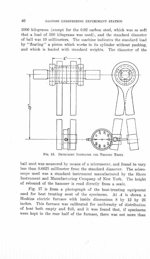
Fig. 16 shows the detrusion indicator used in the torsion testsfor determining the amount of twist in the specimen over a gagelength of 2 inches. The arm is 10 inches long from the axis of thespecimen to the point of contact of the Ames dial.
Hardness tests were made using both the Brinell machine andthe scleroscope. The Brinell machine used was made by the Aktie-bolaget Alpha of Stockholm, Sweden. The standard load used was
*For a more complete discussion of this type of apparatus see Scientific Papers of theU. S. Bureau of Standards, No. 343, and the 1917 Proc. of the Am. Soc. for Test. Materials,Part II, p. 87.
ILLINOIS ENGINEERING EXPERIMENT STATION
3000 kilograms (except for the 0.02 carbon steel, which was so softthat a load of 500 kilograms was used), and the standard diameterof ball was 10 millimeters. The machine indicates the standard loadby "floating" a piston which works in its cylinder without packing,and which is loaded with standard weights. The diameter of the
FIG. 16. DETRUSION INDICATOR FOR TORSION TESTS
ball used was measured by means of a micrometer, and found to varyless than 0.0025 millimeter from the standard diameter. The sclero-scope used was a standard instrument manufactured by the ShoreInstrument and Manufacturing Company of New York. The heightof rebound of the hammer is read directly from a scale.
Fig. 17 is from a photograph of the heat-treating equipmentused for heat treating most of the specimens. At A is shown aHoskins electric furnace with inside dimensions 8 by 12 by 26inches. This furnace was calibrated for uniformity of distributionof heat both empty and full, and it was found that, if specimenswere kept in the rear half of the furnace, there was not more than
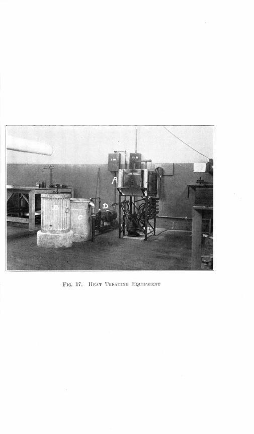
FIG. 17. HEAT TREATING EQUIPMENT

AN INVESTIGATION OF THE FATIGUE OF METALS
10 degrees centigrade variation of temperature for specimens invarious locations in the furnace.
In measuring temperatures, two pyrometers were used, one ofwhich had a platinum-rhodium thermocouple in the center of adummy specimen, which was placed near the center of the pile ofspecimens in the furnace. This platinum-rhodium couple was con-nected to an Engelhard millivoltmeter. A constant-temperaturecold junction was used with this pyrometer, and the cold junctionwas placed in a thermos bottle. The second pyrometer used a chromel-alumel couple connected to a Hoskins millivoltmeter. For this couplea correction was made for the variation of the cold-junction tem-perature, the cold junction being in the millivoltmeter case. Bothpyrometers were calibrated at intervals by means of the freezingpoints of standard metals. In general, the chromel-alumel pyrometerwas used merely as a check on the platinum-rhodium pyrometer.
At B is shown the water-quenching tank, which during the opera-tion of quenching was supplied with running water. At C is shownthe oil-quenching tank. Houghton's soluble quenching oil was used,and during the operation of oil-quenching the oil was circulatedthrough pipes which were surrounded by running cold water. AtD is shown the circulating pump. By this circulation the maximumvariation in the temperature of the quenching oil was kept within17 degrees centigrade.
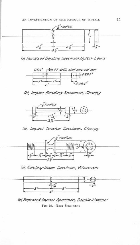
9. Test Specimens.-Figs. 18 and 19 show the various formsof specimens which were used for determining the static and endur-ance properties of the steels.
The shape of the specimen used for the rotating-beam reversed-stress machine, shown in Fig. 18(a), was the result of considerablestudy. It was found in the first place that, if the specimen wasnot reduced in cross-section at the middle of its length, the localizedstresses at the collets where the load was hung would usually causethe specimen to fail at the collets (F in Fig. 4). Various shapeswere tried for the reduced part of the specimen. For one designa part of the specimen was reduced in diameter, and the changeof section from the smaller to the larger was attempted with a taper.For another design a straight reduced section with fillets at theends was used. It was found that specimens broke at the root of

ILLINOIS ENGINEERING EXPERIMENT STATION
(a), Rota/ing Beam Spec/men, Farmer Type
_i krmdius _ -
(4-, Te "- -- SpeC1 tn
(6, Tens/on Spec/men
_t--------- --d
(c), Torsion Spec/m'en
<I C s" I
(d), Compression Spec/men
(e, Rieversea' Torson Specimen, O/sen -Foster-
FIG. 18. TEST SPECIMENS
AN INVESTIGATION OF THE FATIGUE OF METALS
, Reversed Bend/ng Spec/mn, Lpton-L ew/'s
004" ANo. 47 dr///, sF/o sawed out-1 0394"
/ " tO. 3 9 4
(bi, /mpoact Benwdig Spec/7en, Charpy
(c/, /mpact Tension Spec/m'ew, C/arpy
(,d Rota/'ng-Beam'n Spechmen, W/'scon7s/'
/
/6 2" 44',
fe Repeated Impact Spec/men, Do0hb/e-,mn/ner
FIG. 19. TEST SPECIMENS

46 ILLINOIS ENGINEERING EXPERIMENT STATION
the taper, or at the root of the fillet, as the case might be. It seemednecessary, therefore, to have a specimen which changed graduallyfrom one diameter to the other. In the final design the specimen wasformed by a cutting tool swung on a radius of 9.85 inches. For thespecimen shown in Fig. 18 (a) the unit stress calculated by the usualbeam formula gives very closely the actual stress existing at the mini-mum section, as was proved by some tests on celluloid models made atthe laboratories of the General Electric Company at Schenectady,New York, for this investigation. Professor Coker's polarized lightapparatus for determining stress was used. These tests showed thateven when the radius was only 5 instead of 9.85 inches there was nomeasurable increase of stress on the outside fibers due to curvature ofsection. On the other hand, when this radius was only 0.5 inch, itwas found that the increase of stress on the outside fiber was consider-able. With a radius of 9.85 inches there is practically uniform stressover about 0.20 inch near the middle of the span (Fig. 20), the varia-tion in computed stress, due to change of diameter, in this range oflength being only 1 per cent.
- - --- --- --
V)fQ9 ~
(r)I
--------------------
-1
0.3 aZ 0. 0 a/ 0.le 03Inches from Center
Stress Diriu/t/ 0/7 Al//dd/e Par/t of 5}ofcv/2en
FIG. 20. VARIATION or STRESS ALONG FARMER-TYPE
TEST SPECIMEN
m I I
AN INVESTIGATION OF THE FATIGUE OF METALS
Usually the diameter at the reduced section was made 0.30 inch,
but in the case of the stronger steels it was found that with this
diameter they would still break at the collets. It was necessary in
some cases, therefore, to reduce the diameter to 0.27 inch.
In the case of the reversed-torsion specimen, shown in Fig. 18(e),
exactly the same phenomena were exhibited as described for the rotat-
ing-beam specimen. When the ends of the specimens were joined
by a fillet to the smaller diameter at the middle, the specimens al-
ways failed at the root of the fillet. The specimens were therefore
cut down at the middle with the same radius as was used in the case
of the rotating-beam specimen.
A similar problem was encountered with the reversed-bending
specimens used in the Upton-Lewis machine. In this machine the
distance between the jaws holding the specimen is 0.50 inch. The
specimen was first cut down with a radius of 0.75 inch, but it con-
tinued to break at the edges of the jaws because of the local stresses
.existing there. It was, therefore, necessary to weaken the specimen
further and a radius of 0.5 inch was finally adopted. With this
radius the specimens break at the minimum width instead of at the
jaw edges. Fig. 19(a) shows the specimen used for the Upton-
Lewis machine. Of course with this radius the change of section is
rapid enough to produce some localized stress, and this is shown by
the fact that the endurance limits (unit stress which the steel will
withstand indefinitely) determined by the Upton-Lewis machine are
uniformly lower than those obtained from the rotating-beam machine.
Fig. 18 shows the specimens used for the static tests. Fig.
18(b) shows the tension specimen, Fig. 18(c) the torsion specimen,
and Fig. 18(d) the compression specimen. In the compression tests
a spherical-seated bearing block was used, and the specimen was
centered in the machine by means of a template. In the tension tests
spherical bearings were also used, and the shoulders of the specimen
rested in split sockets.
In some cases tension specimens were made from the ends of
rotating-beam specimens. The shape was similar to that of Fig.
18(b) except that the diameter of the reduced part of the specimen
was only 0.25 inch. This form of specimen was used for check tests
and for material supplied in the form of rods less than 0.75 inch in
ILLINOIS ENGINEERING EXPERIMENT STATION
diameter. In all tension tests the elongation was measured on agage length which was four times the diameter of the specimen.
Fig. 19(b) shows the specimen used for the Charpy impact-bending test, while Fig. 19(c) shows the one used for the Charpyimpact-tension test. Fig. 19(e) shows the specimen used for therepeated-impact tests. This specimen was made from the uninjuredends of Farmer rotating-beam specimens. The repeated-impact speci-men is a grooved cantilever beam.
Brinell tests and scleroscope tests for hardness were made onthe ends of the torsion specimens shown in Fig. 18 (c).
The magnetic tests were made on the rotating-beam specimensbefore they were reduced at the center.
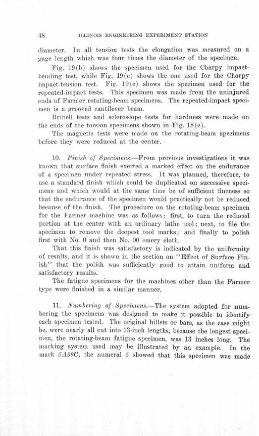
10. Finish of Specimens.-From previous investigations it wasknown that surface finish exerted a marked effect on the enduranceof a specimen under repeated stress. It was planned, therefore, touse a standard finish which could be duplicated on successive speci-mens and which would at the same time be of sufficient fineness sothat the endurance of the specimen would practically not be reducedbecause of the finish. The procedure on the rotating-beam specimenfor the Farmer machine was as follows: first, to turn the reducedportion at the center with an ordinary lathe tool; next, to file thespecimen to remove the deepest tool marks; and finally to polishfirst with No. 0 and then No. 00 emery cloth.
That this finish was satisfactory is indicated by the uniformityof results, and it is shown in the section on "Effect of Surface Fin-ish" that the polish was sufficiently good to attain uniform andsatisfactory results.
The fatigue specimens for the machines other than the Farmertype were finished in a similar manner.
11. Numbering of Specimens.-The system adopted for num-bering the specimens was designed to make it possible to identifyeach specimen tested. The original billets or bars, as the case mightbe, were nearly all cut into 13-inch lengths, because the longest speci-men, the rotating-beam fatigue specimen, was 13 inches long. Themarking system used may be illustrated by an example. In themark 5A39C, the numeral 5 showed that this specimen was made

AN INVESTIGATION OF THE FATIGUE OF METALS
of steel number 5 or chrome-nickel steel; the letter A, that the speci-men was from bar or billet A; the numeral 39, that it was located 39inches from the end of the bar; and the letter C, that the specimenoccupied the position C in the cross-section of bar A, according tothe diagram for cutting up the bars which had been adopted forsteel number 5.
Fig. 2 shows the plan which was used in cutting up the varioussteels. Taking Steel No. 4, 0.37 carbon sorbitic, as an illustration,the numbers directly above the diagram show that one set of speci-mens was cut up from 0 to 13, or 13 inches long; that another setwas cut up from 13 to 16, or 3 inches long; another from 16 to 21,or 5 inches long, etc. This was the first steel cut up; all succeedingsteels were cut up into 13-inch lengths.
12. Procedure in Tests-Accuracy and Sensitiveness.-Theregular static tension and compression tests were carried out on a100 000-pound Riehle machine. This machine was calibrated bymeans of calibrating levers and dead loads before it was used fortesting purposes. It was found that the machine was sensitive to10 pounds up to 23 000, beyond which it was not tested. The ma-chine was accurate to about 0.6 per cent at 5000 pounds and to 0.4per cent at 20 000 pounds.
For the static tension and compression tests a Ewing exten-someter was used to measure deformation over a gage length of 1.25inches. This extensometer was calibrated with a Brown and Sharpemicrometer screw, and it was found that one division on the exten-someter scale represented a unit deformation of 0.00006925 inch perinch of gage length, or the sensitiveness was 0.000006925 inch perinch by estimation.
The aim in the static tests being to get at least ten incrementsof strain (as shown by extensometer readings) up to the yield pointof the material, the following procedure was adopted. An initialload, which in the tension test was 400 pounds, was put on the speci-men and a reading taken on the extensometer. Load was then ap-plied until the extensometer showed the desired increment of de-formation, and load and extensometer readings were recorded. Theload was then reduced to the initial reading of 400 pounds and theextensometer reading was again recorded. The load was then in-
ILLINOIS ENGINEERING EXPERIMENT STATION
creased until the extensometer showed the standard increment above
the previous reading, and, after reading load and extensometer, the
load was again reduced to 400 pounds. This procedure was con-
tinued up to the vicinity of the elastic limit, when smaller incre-
ments of extension were used-usually about half the initial values-
in order to determine the form of the curve more exactly.
The purpose of this procedure was to make a determination of
the elastic limit as based on permanent set, as well as the more com-
monly used limit based upon proportionality of unit stress and unit
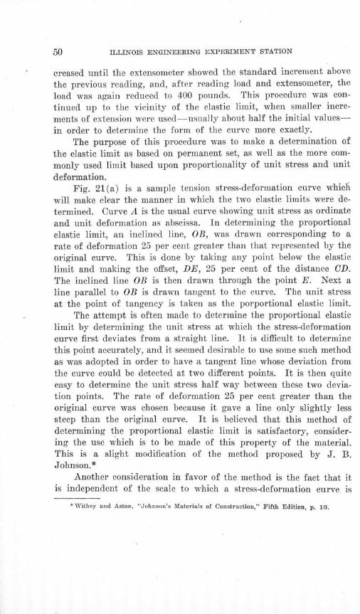
deformation.Fig. 21(a) is a sample tension stress-deformation curve which
will make clear the manner in which the two elastic limits were de-
termined. Curve A is the usual curve showing unit stress as ordinate
and unit deformation as abscissa. In determining the proportional
elastic limit, an inclined line, OB, was drawn corresponding to a
rate of deformation 25 per cent greater than that represented by the
original curve. This is done by taking any point below the elastic
limit and making the offset, DE, 25 per cent of the distance CD.
The inclined line OB is then drawn through the point E. Next a
line parallel to OB is drawn tangent to the curve. The unit stress
at the point of tangency is taken as the porportional elastic limit.
The attempt is often made to determine the proportional elastic
limit by determining the unit stress at which the stress-deformation
curve first deviates from a straight line. It is difficult to determine
this point accurately, and it seemed desirable to use some such method
as was adopted in order to have a tangent line whose deviation from
the curve could be detected at two different points. It is then quiteeasy to determine the unit stress half way between these two devia-tion points. The rate of deformation 25 per cent greater than theoriginal curve was chosen because it gave a line only slightly lesssteep than the original curve. It is believed that this method ofdetermining the proportional elastic limit is satisfactory, consider-ing the use which is to be made of this property of the material.This is a slight modification of the method proposed by J. B.Johnson.*
Another consideration in favor of the method is the fact that itis independent of the scale to which a stress-deformation curve is
* Withey and Aston, "Johnson's Materials of Construction," Fifth Edition, p. 10.

AN INVESTIGATION OF THE FATIGUE OF METALS
NMI
KN
- ~lit,
zS- TOU)
r&1
0U)
TO
rz2a)E)
U)
04
eW -- ad ql/ q1 'ssawqp pu

ILLINOIS ENGINEERING EXPERIMENT STATION
drawn. The method will determine in all cases points where theproportional increase in rate of deformation is the same. This isnot true for the method which makes use of the first deviation froma straight line; nor is it true of the method which employs a secantdrawn parallel to the original curve, and which uses the unit stressat the intersection of the secant line and the curve as the elasticlimit.
The elastic limit as based upon set may be called a set elasticlimit. The set curve was plotted as shown at F in Fig. 21(a), thescale for set being usually about five or ten times that used for thecurve A. The set elastic limit was taken as that unit stress at whichthe rate of permanent set increased appreciably. This method waschosen because it was assumed that too much reliance should notbe placed on the set as determined at low stresses, but that a pointin the curve should be chosen where there was no doubt that perma-nent set had commenced and was increasing.
The technique used in arriving at this value was based upon theidea of getting an offset for drawing a tangent line which would beabout the same as the offset used in getting the inclined line OB,Fig. 21(a). Since the modulus of elasticity for steels is practicallyconstant at 30 000 000 pounds per square inch, the inclined line OBused with curve A has at a unit stress of 30 000 pounds per squareinch a horizontal offset from the original curve of 0.00025 inch perinch, MN in Fig. 21a, and at 60 000 pounds per square inch the off-set would of course be 0.0005 inch per inch. The line for zero setwould be a vertical line from 0'. At a unit stress of 60 000 on theset curve, therefore, a point, G, was determined which had an off-set, KG, from the line of zero set of 0.0005 inch per inch. A linethrough 0' and G determined the inclined line, and one parallel tothis and tangent to the curve determined the elastic limit as basedupon set.
Tables 3 and 4 show that the proportional elastic limit and theset elastic limit as determined by the above methods are very nearlythe same in magnitude in tension, compression, and torsion. In somecases the proportional limit is slightly the higher, and in other casesthe set limit is the higher. Since there is so little difference in thesetwo limits it seems obvious that the tedious method necessary todetermine the set limit may be dispensed with in future tests of steels.
AN INVESTIGATION OF THE FATIGUE OF METALS
In the torsion tests readings of twisting moment and twist were
taken in a manner similar to that already described for the tension
and compression tests. The proportional elastic limits and the set
elastic limits were also determined in a manner similar to that previ-
ously described. The micrometer dial of the detrusion indicator
shown in Fig. 16 reads directly to 0.001 inch, and the reading can be
estimated to 0.0001 inch. With this indicator, therefore, the twist
of the specimen over two inches gage length can be read to 0.0001
radian directly, and to 0.00001 radian by estimation.
From the fatigue tests the fundamental information desired was
the relation between the unit stress applied to the specimen and the
number of cycles of stress necessary to cause rupture. The general
practice with the Farmer machines was to stress the first specimen
high enough so that it would break in a comparatively short time;
then reduce the stress in the succeeding specimens, until finally a
unit stress was arrived at which the steel could withstand for
100 000 000 cycles without failure. Wherever possible these long-time tests without failure were run on from three to five specimensfor each of the steels investigated.
All values of stress calculated for the Farmer specimens arebased upon the external load applied to the specimen, the weight ofthe specimen itself being neglected.
Only one Upton-Lewis and one Olsen-Foster machine were aviail-able. Consequently it was not practicable to make runs up to100 000 000 cycles. In these machines, therefore, the stress was de-termined at which the specimen could withstand 2 000 000 cycleswithout failure. It will be found by consulting the curves whichwill be shown later that this determines the endurance limit fairlyclosely.
The Brinell and the scleroscope hardness tests were made on therectangular surfaces of the uninjured ends of the static torsionspecimens, the impressions being at right angles to the axis of thespecimen. In each case impressions were taken on two adjacentsides, and in getting the diameter of the Brinell impression a micro-scope was used with a micrometer eyepiece which read to 0.1 milli-meter directly, and to 0.01 millimeter by estimation.
It is not thought necessary to describe in detail the techniqueof impact tests or of magnetic tests.

ILLINOIS ENGINEERING EXPERIMENT STATION
III. TEST DATA AND RESULTS
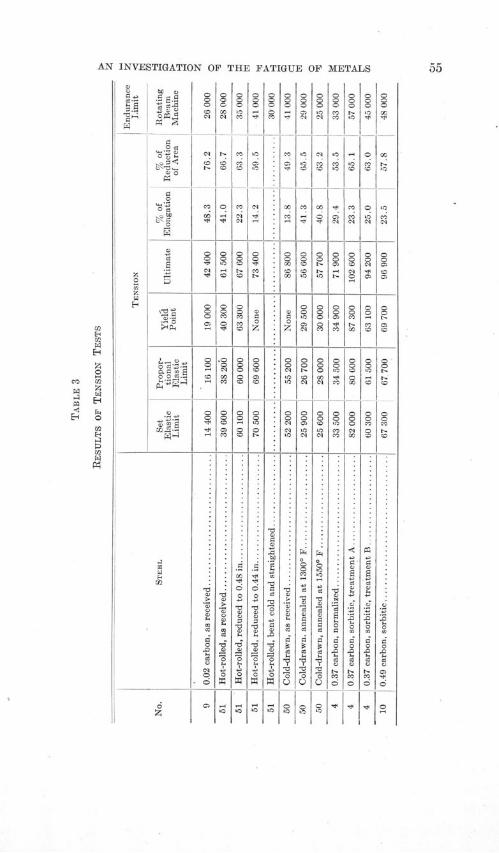
13. Summary of Test Data and Results.-Tables 3, 4, and 5
give summaries of test results. Table 3 gives the results of the
tension tests, and also the endurance limits as determined from the
rotating-beam tests, so that comparisons may be conveniently made.
Table 4 gives the results of the compression and the torsion tests.
Table 5 gives the results of the hardness and the impact tests and
also the endurance limits as determined by the rotating-beam, by the
Upton-Lewis reversed-bending, and by the Olsen-Foster reversed-
torsion machines. The last column in the table gives the "FR" point
as determined by the Francke* test.
Table 6 shows a sample summary sheet, in this case for treat-
ment A of the chrome-nickel steel. This table shows the number
of results which were averaged in obtaining the results given in
Tables 3, 4, and 5. Each Brinell and scleroscope result given in
Table 6 is the average of several readings. Figs. 21-23 inclusive
show representative stress-strain diagrams for tension, compression,
and torsion tests.Figs. 24-31 inclusive show the test results obtained on the Farmer
machines for reversed-stress tests of the various steels. The method
used in plotting these diagrams is discussed on page 90. Figs. 32
and 33 show similar diagrams obtained from the tests on the Upton-
Lewis reversed-bending machine; while Figs. 34 and 35 show the
diagrams for the Olsen-Foster reversed-torsion machine.
Fig. 28 shows S-N curves obtained in making a study of the
effect of changes of shape on the endurance strength of steel. Fig.
29 shows similar curves obtained in making a study of the effect
of surface finish on the endurance strength; while Figs. 30 and 31
show the S-N curves obtained in making a study of the effect of
previous over-stressing on endurance strength.Table 7 gives the results for all fatigue tests so far made in the
course of the investigation.The "rise of temperature" tests for endurance limit under re-
versed stress are treated in a special chapter, and the data for thosetests are given in that chapter.
*Proc. Am. Soc. for Test. Materials, Vol. XX, Part II, p. 372, 1920.
AN INVESTIGATION OF THE FATIGUE OF METALS
*o1,; C)maI
K
C)OC)|
_r°
0
.5
0) 0 CC.S
CC) -
000
CO
00
00C
0'C'C1
0C11
0
'C
0
0
0(0C3)CC
CO)
CC
00
0CC)
0
0
C)0)z
000
0C,
000
'C
CC)
'C
0)
C)
>0
'C
CO
0
t,,0
05
0)1
0
C)o
CO
(0'C
0
0
N
0
80
00
t0
0r0g)oC
0
0
10>0
0
CO
CO)CO)
C) C) C) 'C)
0 ' C '
§g10C
0
to0
<0
CO)
CC)
g
CO
00
z0
0
CC)
00CC)
CC
00
CCC)
00C))CC)
00
CCCC)
COC0
g
I
O1t0 :01 Z0 *f 'IV 11 0

ILLINOIS ENGINEERING EXPERIMENT STATION
4) 444)
~
0 0~
z0
0040
04, ~
4)0
00
44
0
'0-0'-0
44-40 40~.
44 0....
o o
01 0m4 4
o o00
N 44
44
44
N
444444
04444
44
4444
4444
44
44
4444
4444
00z
N04
N
00CD
004
i44
44
4444
44
4444
4444
C444444N
444440
40
(N
04
0404
44
0444N»
44H
44
44N
(N
44
0444
04
4444
4404
44440404
4444
44
4444
44N
44444404
4C
44
N
4D44
0
4444
4o
1>44
4444
AN INVESTIGATION OF THE FATIGUE OF METALS
0
:0
0~
o d.
o cP¾,o 0 .g
CM
CICO
0011C.0
0
0
C,0
CGO
0
00030
00
C00
0t0
§lGO
OS I -
0
00tC CO
Ii- It,

ILLINOIS ENGINEERING EXPERIMENT STATION
CO
H
cctC
CD
CCa-
H;
C.,
r CDCDHH
CDHCD
F-;CCCD1
ffl a< Cfr
CI
H
6D0Dp4
ce .i .2w
I| 15, z PC0
CC .4
2pE
C' s« C aCD
I0 0 0 C
3 a 0 k.
t
C6C
to~
IN
I - .2
^S-d
z
0
04
0
0
CO
4
00
0
0
o4
C9
04
00
00
COCC
CD
04cC
CD
'0
0)
0D
CD
Cd
C
8D
£D
0
0
CD
0C
CD
C
CD
CDCCC
0
CD
CC
0
CC
C
C
0
CD0
.0CC
CDCCd
CC
0CO
0
CD
04
F-C
CD
CO0404
0>0
>0
CDa
CD
0o00COCO
CD0
00
0
C)0
COCO
CD
0
0c0
00
C,3
Co
N
04
C9
0
Cs
o3
04
CD
0
00
00
00<
N
sD
04
CCl
04
03
04
004
a"
CO
0
'0'
0
CO
C
o
o
-D
CC
03
Cd
N<
CD
C
CD
CD
C
C
CC
CD
04
CO
000
0C0
CC0CD'02
0
04
04
CD
0404
CO04
04
C
.0Ca
04
0
0

AN INVESTIGATION OF THE FATIGUE OF METALS
0C)0
~00
C
0
H
C .0C)~ ~
0 0CC ~~ K~*- ~E
H H
C, .00CC) C)O
- 0~ C)OH
.0.O*~ ~ CC
~~ )-~E
~C)C~C
^*00
Co4
6°o2 S
CC~ C*C C).CC~ CC ~.O
000 C)00.
CCC C)0~ TC)C) 0')-0
*0C) -
C
CO CO COCO CO Co'C) -
000 00 0CO ~C)CO Co
00
0^
0^
0
0O0
00
CO
'0
CM
CMC
000
000
CO
CM
CM
CO
CoCo
C- CC Co 'C Co 'C) CoCo Co C.. Co C.. - CoCo - COO C- t
.1.:Co
00
CM10
* 0
* 0
0 0 0
CO 0 Co0 0 COS
CO Co 0
0 00 CO
CCC Co CO
'C) OC 0-H *-C Co)
- -Cf COCOCo CO
COCM CO
000Co
CO O
C D00C
10
CO CO
rC1 CO
0 Cot~- Co.- Co
GO CO
CO C0C- C-
CO
CO
COCCC
CO
C.-
Co
000C-
CMtD

ILLINOIS ENGINEERING EXPERIMENT STATION
S-o
S3 01
. 0
E~.0
0
oil'
^l4)
Joo
fl
olH0O
r0.
- 0
S-o
ci 0'
s) I
.0
0
.~- e
4)4)
040
0
00
40
N
01
40
0000
co
0q
cc
10
.000
go
C11
i0
N-
COI-0
C)
(0
40
0>r04
000^
01<00N
40
0001N
4)4,4

AN INVESTIGATION OF THE FATIGUE OF METALS
TABLE 6 (Continued)
REPRESENTATIVE SUMMARY SHEET
Tests of Chrome-Nickel Steel, Treatment A
TORSION TESTS
Propor-Set tional
Specimen Elastic Elastic Yield Modulus ofNumber Limit Limit Point Elasticity
lb. per sq. in. lb. per sq. in. lb. per sq. in. lb. per sq. in.
5C26C 72 500 72 000 93 750 11 500 000
5D13D 77500 78000 86100 11 380 000
5A91B 74 500 72 500 84 800 11 640 000
5B65A 72 500 70 500 83 200 11 630 000
5A39A 70000 72000 80 750 11 470 000
5C78A 69 500 69 500 80 500 11 420 000
Average 72 800 72 400 84 900 11 510 000
HARDNESS
Brinell Scleroscope
302 36
302 36
293 36
289 36
273 37
286 35
291 36
CHARPY IMPACT BENDING CHARPY IMPACT TENSION REPEATED IMPACT
Energy Energy Energy Reduc- NumberSepci- of Speci- of Speci- of Elonga- tion of Speci- ofmen Rup- men Rup- men Rup- tion Area men Double
Number ture Number ture Number ture Number Blowsft. lb. ft. lb. ft. lb. per cent per cent
5B78B 46.1 5B78B 47.8 5B78B 186.8 7.0 63.7 5D13A 1359
-5A104B 47.1 5A104B 45.4 5A104B 181.2 24.0 63.4 5A26A 1214
-5A26B 45.2 5A26B 46.9 5A26B 150.4 17.0 62.3 5BOB 1099
5C39C 44.9 5C39C 45.4 5C39C 180.4 22.0 61.7 5A117A 886
5C91C 41.8 5C91C 43.2 5C91C 170.3 15.0 57.2 5A130A 806
Average ................. 45.4 ......... 173.8 17.0 61.7 ... ..... 1073

ILLINOIS ENGINEERING EXPERIMENT STATION
C*cC
k)
~:3 ~-
'K.-Cl)
)- ~-
v~N
I'
-4 - - -4
';
N.
' ss <^
'W ,•" if/ - AC/.' ql/z//7
AN INVESTIGATION OF THE FATIGUE OF METALS
\ |t
o
0
oIo'ZZ
-^ ~ 1.b /S9Nt^- ^-
^ --
N.i -^^ '^^ ^
N
FA
E-4
0
m
0
(1 2
z03
EJrJ
Elz
a.
CO2
cii
h lZ- -,
- . --- -
Cr) -I^\
!
*/ssc Joa'/ 'ss-ff; a/^

ILLINOIS ENGINEERING EXPERIMENT STATION
K
FIG. 24. S-N DIAGRAMS FOR 0.93 CARBON STEEL AND FOR 1.20 CARBON STEEL,
ROTATING-BEAM TESTSLogarithmic abscissas give thousands of cycles for rupture
130000IZOOOO - g . t - --- - --- - --- -120000 --
/0000 0 -
Stee/ Na 6, 0.93 C., Troositc80000
7 000060000 - --
-0
50000 NSteel Noa., 093 C., Sorb/llc'
40000 -
/30000 - - -____ - -
/.6 , 293 C-, Pe_ _r/_ Z_
/0000 --- -- - - - -/000 Cyc/es for uRpture. M fN
140000130000 - -/ 20000 - -- - - - - - - - -- - - -
/80000 8 - --- - --
Steel ao. I, 120 C.,70000-/ , r /
60000 - --
40000 No See/a, 120 C, Normalized
30000 - __ ______ - -
~0
N
K(1)

AN INVESTIGATION OF THE FATIGUE OF METALS
/9uVLL r ---- -- i --- i--------- ,-130000--/0000 - -//0000--/00000 -
/40000 - _* -Treafmeant
70000 - ____1 __ -. 1-
6/0000 * -T•t -- a I -----/10000 - ___r he/o----(------ -*
Trament C Tret mentB
/0000-
90000 --- - --- --__ - --- -- ---- --
30000
20000
/00000
_____ S te/N 4, rr37C, Sorb/-A_
340000 -130000/I00000/10000I00000soooo• -- c " - ----- - -
80000 --- - - - - - ------ --
70000
0 --0 ^^ Wel~o4, 0., 37 C,- ýor6i5 ^-A
40000 -' "
30000- TSteel o. 4, 037C, NonWa/Z9 J
FIG. 25. S-N DIAGRAMS FOR CHROME-NICKEL STEEL AND FOR 0.37 CARBON
STEEL, ROTATING-BEAM TESTSLogarithmic abscissas give thousands of cycles for rupture
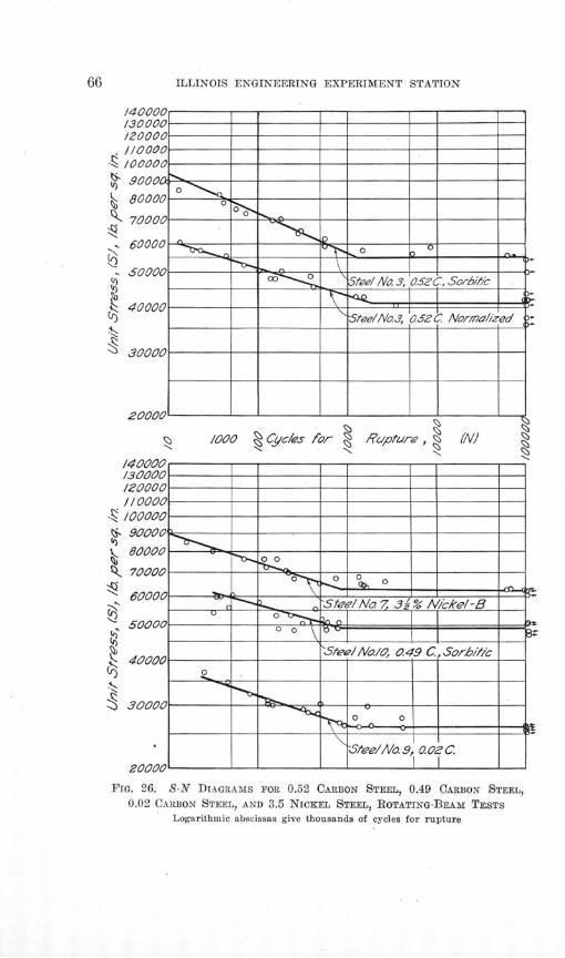
ILLINOIS ENGINEERING EXPERIMENT STATION
0
/10000090000
80000
70000
60000
S0000
40000
20000
S /000 Cy,,c/es for A'pre
140000/30000 - -2000 -1/0000-- -
/00000 - - -
90000-
80000 -- =o-70000o
60000
50000 o- 0 0
40000 __ Stee//Va/O, 0.49 C., Sorb0///
o
30000 --
Stee/ANa 9, 002 C.
2000 - -
I4(GJ1UI130000/20000J //7000
0
N
~I)
(()
FIG. 26. S-N DIAGRAMS FOR 0.52 CARBON STEEL, 0.49 CARBON STEEL,0.02 CARBON STEEL, AND 3.5 NICKEL STEEL, ROTATING-BEAM TESTS
Logarithmic abscissas give thousands of cycles for rupture
-
-
-
-
-
-
2 Ne'rma/,~ed
~1NI
ý30000
tieel I.3, 0.52
Stee/aNo.3, 0.2
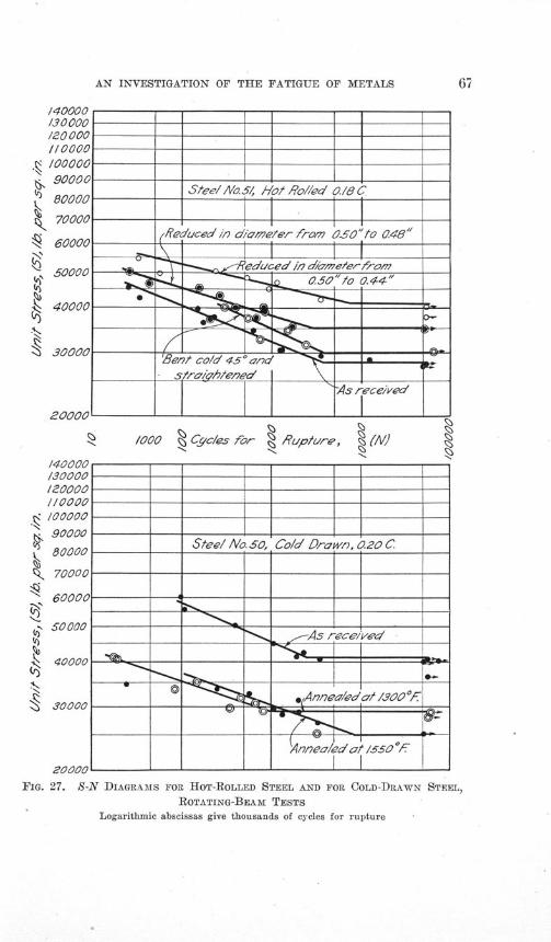
AN INVESTIGATION OF THE FATIGUE OF METALS
/-.L/L/CUV ----- --- ------ -- ------ -- ----- --
130000/ZOOOO1•0000-/00000-90000
cK 80000o__ Stee/ Na SO, Co/d Drawn, 0.20 C80000
70000
60000-
500 -- ^- -,-A-- - -----:
40000
'I) o o o • ___ _ _ _ _S ® a A nnea/0d,/ 3°oo'F
ooAnnea/e t Is0
20000 1-- - - - - ---- - --- -
FIG. 27. S-N DIAGRAMS FOR HOT-ROLLED STEEL AND FOR COLD-DRAWN STEEL,
ROTATING-BEAM TESTSLogarithmic abscissas give thousands of cycles for rupture

ILLINOIS ENGINEERING EXPERIMENT STATION
S e/No. 9,
Z .-
."f7 i et radIus
*
o* S 5_ o
S^» ^ ^ _ _ ^
______~S~zore Sho4'/de,-J_____
/((UUL
60900
%40000
,)30000
20000
/i-
JflAA/'
FIG. 28. S-N DIAGRAMS SHOWING EFFECT OF SHAPE OF SPECIMEN,
ROTATING-BEAM TESTS
Logarithmic abscissas give thousands of cycles for rupture
A<
<
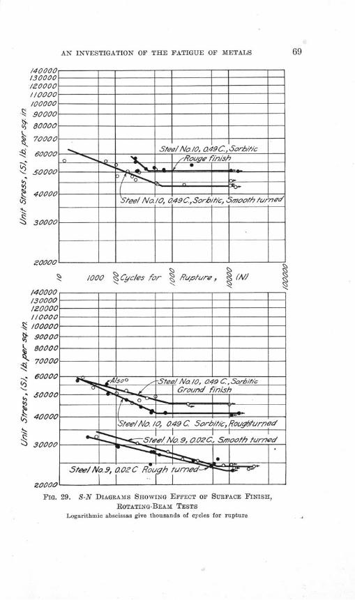
AN INVESTIGATION OF THE FATIGUE OF METALS
/40000130000/20000 - - -
,Ioa00c ----- - ---- - --- -- --- -
100000 ---- - ------- -- ---- - ---- -I 90000 - -
680000
70000 E
60000 - Steel Nao /0, 049 C, S0orh1icS o 6000 - ,Rouge f/n/sh
N. 50000 -- -"-- -0 _ ___
40000 -- -- -Steel No /O, a49C.,Sorb•hic, S 1ooth/ turned
-----C - -__----__ 1---30000- -- - -- - -- - -
Z0000-
140000 - --
130000 - - -0000 - -§* tool %----/----- - ---- - ---- -/
S0000-
80000
70000
0000 /00l -Steel No. / 049 C, Sor/,bt/c
_0 _ I_ Gro6und finish
S0tee/No. /0, 0. 49 C Sorb//c, Rougffured
S30000na A/a 9, .OCC, 5,woofah tur7ed
5 tee/l No.9, 0.0C Rouh furned-
20000
FIG. 29. S-N DIAGRAMS SHOWING EFFECT OF SURFACE FINISH,ROTATING-BEAM TESTS
Logarithmic abscissas give thousands of cycles for rupture
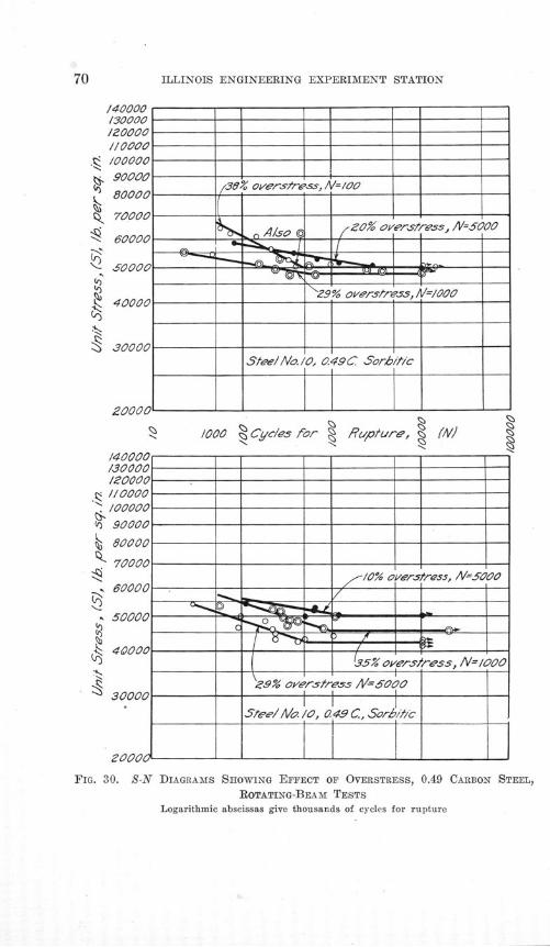
ILLINOIS ENGINEERING EXPERIMENT STATION
/40000130000/Z00001/0000/0000090000
80000
70000
60000
60000
40000
£30000
finnnn
v, 41ft5o
t5 io
~ES, / /= 00
AL.
38-
51teel/No.lO, 0.49UC Scrhlt/c
S000 000 Cyc0es for Rupture, //(
/40006-10\-0- ---130000/20000 -
/10000 -- ---- - --- -- ------ -/00000 ---- --- - --- -
90000
80000- -- - - ---
70000 -- --/0% overstress, /V=SO0
60000-
50000-
4000005% overs/ress, N=/I000
9% overstress /V=5000
Stee/ Ala o/, 0 49 C, Sorbi/,c
20008 1-- - -- ---- - ---- - ---- -
FIG. 30. S-N DIAGRAMS SHOWING EFFECT OF OVERSTRESS, 0.49 CARBON STEEL,
ROTATING-BEAM TESTS
Logarithmic abscissas give thousands of cycles for rupture
~29% overstress, A"=VOOO
00

AN INVESTIGATION OF THE FATIGUE OF METALS
IqWUa& - -- -- ----- -] ---- I-[ ---- ---/30000 --- -- ------ _ -- ---- - --- --
/20000 ---- -- __ --- -- ---- -- --- -1/0000//0a00
, /00000S 30000 --0
70000
S0000
* 70000 .20% overstress, AV0 0- --
400 SteelAlo. /. 0 C, SorlitlcS40000
130000--- -
200001-- ------ -- ------ ----
/O00 C c/es for 1 Rupture, !(N!
Fla. 31. S-N DIAGRAMS SHOWING EFFECT OF OVERSTRESS, 1.20 CARBON STEEL,ROTATING-BEAM TESTS
Logarithmic abscissas give thousands of cycles for rupture
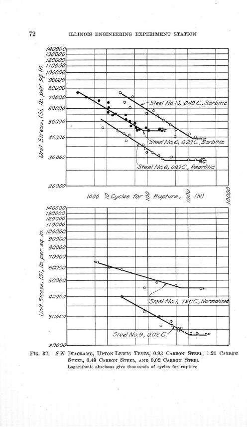
ILLINOIS ENGINEERING EXPERIMENT STATION
/40006T ____ ____-- __---130000\ -- - --- - - -- - -/20000\- -
/00000tOOOOO ---- ------ -- ------ -- __ ---- -90000
80000
70000- - ON- -- ---- -- ------ -s o -Seel No. /O, 0.49 C, Sorb//,c
60000 --
50000-------- J/ A---^,Q------------
soiooo----/^s-for % -- tu------
4 000 0 _ 0 9-r b0-0 SteeAlo. 6, 0.93 C,
30000
__S______Seel/Va 6, 093 C, Pear//c___
120000
/000 '1 C!,c/'s for I 4'IJ/r6, % (IV140000----- -130000 - -
/20000 - - - -
70000 - - - -90000o ---- - ------ -- ---- - ---- --
80000 ---- ___ --- -- ---- - --- --
80000 - - -
7SOOOO ----- ----- '3^- ---- --
40000 - - - -4000 'Stee/Na /, /ZOC., Norma///z
---- ____ ________ "_____________I
Stee//Va0.9, 0Z C.7 a-zi
20000 1-- I-
FIG. 32. S-N DIAGRAMS, UPTON-LEWIS TESTS, 0.93 CARBON STEEL, 1.20 CARBON
STEEL, 0.49 CARBON STEEL, AND 0.02 CARBON STEELLogarithmic abscissas give thousands of cycles for rupture

AN INVESTIGATION OF THE FATIGUE OF METALS
140000130000 -- -/X0000iloooo -- - --- - ---- - ---- -____
/00000 --
0.90000
80000 - -Stee/l/o. , Chrome-!VIce/-A
70000 -
60000 -
40000 -
40000Steel No3, 05Z C, Sor't/,,a,-
30000 --- ___ ------ -- __S__
Stee/l No.3,05. C, Normao' /ed
20000 -
/ Cyc/es for R isup ure, (W h
1400006--| ------- 1 ----- -- - -/30000 -- ------ - ------ - ------ -/Z0000-' - -- ------ -- ------ -1/0000 - ------ - ------ - ------ -/00000 - - -- - ----- -
-90000 - ------ -- ----- -
70000 ...Wiscons ach -
(_ S teel / N a 4 037 C Sorblc _-_6 50000
S4000000
30000 - -nr - --
wSteel No.4, 037 C, Norm/a/lzed
FIG. 33. S-N DIAGRAMS, UPTON-LEWIS TESTS, 0.52 CARBON STEEL, 0.37 CARBONSTEEL, AND CHROME-NICKEL STEEL: TESTS ON WISCONSIN MACHINE,
CHROME-NICKEL STEELLogarithmic abscissas give thoAsands of cycles for rupture
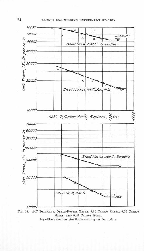
ILLINOIS ENGINEERING EXPERIMENT STATION
70000
50000
S40000
?430000
4)20000
I 0/ 00
0p
0-0
o 7/000 Cyc/es for % Rupture, (AI |
70000- - - -
S60000 _____
50000 - - - -
40000 - - -
S teeNo. a, ao ____
FIG. 34. S-N DIAGRAMS, OLSEN-FOSTER TESTS, 0.93 CARBON STEEL, 0.02 CARBONSTEEL, AND 0.49 CARBON SEE , S
Logarithmic abscissas give thousands of cycles for rupture
*^-30000 -- - -- se'--- - --- -
N..-20000 ---- - a -- - ---- - ---- -
/0000 - - - - --- - --- - --- --
Logarithimic abscissas give thousands of cycles for rupture
Stee//Vae, 0.93 C, Troos
Steel/ o., 0.93 C., Pear///c
ilL2 resu/i&
ttic

AN INVESTIGATION OF THE FATIGUE OF METALS
6 0000
160000
Steel A/a s, Chrome-/ceo m/-B -• 3 0000C - -- ---- -- ----- -- _
Jr --
2000 -
I000 ______
/OOo 0 Cyc/es for 1Rupture, (IM)
70000
60000 - - -
i'6,£0 0
0C - -- -- --- - - -- --- - -- ----- -
"40000 - --
o o-.30000 ----- -- -
2000
Steel/ Va 4, 0.37 C. Norma/ied- o
10000 -
FIG. 35. S-N DIAGRAMS, OLSEN-FOSTER TESTS, 0.37 CAiRBON STEEL, ANDCHROME-NICKEL STEEL
Logarithmic abscissas give thousands of cycles for rupture
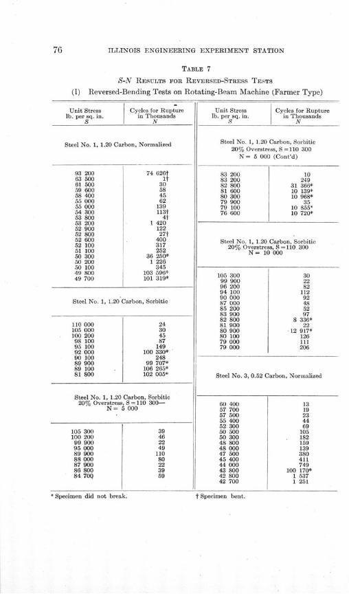
ILLINOIS ENGINEERING EXPERIMENT STATION
TABLE 7
S-N RESULTS FOR REVERSED-STRESS TESTS
(I) Reversed-Bending Tests on Rotating-Beam Machine (Farmer Type)
Unit Stress Cycles for Rupturelb. per sq. in. in Thousands
S N
Steel No. 1, 1.20 Carbon, Normalized
93 200 74 626t63 500 1t61 500 3059 600 5858 400 4555 000 6255 000 13954 300 113t53 800 4t53 200 1 42052 900 12252 800 27t52 600 40052 100 31751 100 25250 300 36 250*50 200 1 22650 100 34549 800 103 596*49 700 101 319*
Steel No. 1, 1.20 Carbon, Sorbitic
110 000 24105 000 30100 200 4598 100 8795 100 14992 000 100 330*90 100 24889 900 99 707*89 100 . 106 265*81 800 102 005*
Steel No. 1, 1.20 Carbon, Sorbitic20% Overstress, S = 110 300-
N= 5 000
105 300100 20099 90095 00089 90088 00087 90086 80084 70Q
Unit Stress Cycles for Rupturelb. per sq. in. in Thousands
S N
Steel No. 1, 1.20 Carbon, Sorbitic20% Overstress, S = 110 300
N = 5 000 (Cont'd)
83 200 1083 200 24982 800 31 366*81 600 10 139*80 300 10 968*79 900 3579 100 10 855*76 600 10 720*
Steel No. 1, 1.20 Carbon, Sorbitic20% Overstress, S = 110 300
N= 10000
105 300 3099 900 2296 200 8294 100 11290 000 9287 000 4885 200 5283 900 9782 800 8 336*81 900 2280 900 12 917*80 100 12679 000 11179 000 206
Steel No. 3, 0.52 Carbon, Normalized
60 40057 70057 50055 40052 30050 50050 30048 80048 00047 50045 40044 00043 80042 80042 700
- ,,IevlmtU tnu flUb ur,~nt. t Specimen bent.
1319234469
105182159139380411749
100 170*1 5371 251
Specimen did no
k.
t Specimen bent.

AN INVESTIGATION OF THE FATIGUE OF METALS
TABLE 7 (Continued)
S-N RESULTS FOR REVERSED-STRESS TESTS
(I) Reversed-Bending Tests of Rotating-Beam Machine (Farmer Type)
Unit Stresslb. per sq. in.
S
Cycles for Rupturein Thousands
N
Steel No. 3, 0.52 Carbon, Normalized (Cont'd)
42 20041 90041 60041 90040 40040 40037 30035 800
4 124t100 000*100 168*112 944*
3 544102 332*102 738*100 614*
Steel No. 3, 0.52 Carbon, Sorbitic
89 800 1085 000 1382 200 3778 100 4075 400 5773 000 7370 200 18369 500 14865 500 30364 000 28262 000 56259 000 55958 400 8 79057 500 1 52756 200 5 54055 800 63 265*54 100 103 387*49 800 108 987*
Steel No. 4, 0.37 Carbon, Normalized
49 100 1If48 800 0145 100 9043 900 4t42 200 4t42 000 23440 400 57240 000 0t40 000 4t40000 1 86139 900 17t38 100 28038 100 45738 100 1 17537 700 2 02737 300 1 66736 600 77036 200 884
* Specimen did not break.
Unit Stresslb. per sq. in.
S
Cycles for Rupturein Thousands
N
Steel No. 4, 0.37 Carbon, Normalized (Cont'd)
35 70035 40035 10035 10034 70033 90033 90033 80033 20033 10032 000
1 5721 5363 1544 4638 478
106 588*107 569*
9 937103 602*
3 248101 415*
Steel No. 4, 0.37 Carbon, Sorbitio
Treatment A
81 40074 70071 60064 70062 10059 60058 80058 70057 20056 20055 600
4485
136631
1 926292641
1 364100 965*94 060*90 179*
Steel No. 4, 0.37 Carbon, SorbiticTreatment B
80 00069 90064 10063 00060 20059 80057 20055 10052 60050 50050 00049 00047 20047 10045 30044 20040 300
t Specimen bent.
36
35180108144262237373
2 103101 403*
585766
101 566*56 550
108 518*100 456*

ILLINOIS ENGINEERING EXPERIMENT STA N
TABLE 7 (Continued)
S-N RESULTS FOR REVERSED-STRESS TESTS
(I) Reversed-Bending Tests of Rotating-Beam Machine (Farmer Type)
Unit Stress Cycles for Rupturelb. per sq. in. in Thousands
S N
Steel No. 5, Chrome-Nickel, Treatment A
120 000 5111 300 6105 300 13100 100 3095 200 5989 800 7685 800 23083 100 9580 800 16879 600 21277 600 30676 900 28975 600 1 30575 300 80773 100 76570 200 94569 200 29868 800 99 908*68 600 27268 500 82468 200 82968 000 1 36067 800 100 735*67 200 105 669*65 200 101 602*65 200 83 36462 800 101 239*
Steel No. 5, Chrome-Nickel, Treatment B
89 800 2586 000 3083 000 9477 700 8874 700 18674 700 22370 100 40567 900 81065 900 90765 500 1 81865 200 1 22765 200 2 96264 700 34 31464 500 102 200*64 500 103 979*
Unit Stress Cycles for Rupturelb. per sq. in. in Thousands
S N
Steel No. 5, Chrome-Nickel, Treatment C
102 100 - 495 100 3186 000 5680 800 12775 000 18072 600 24870 600 40569 800 3 51468 800 1 02768 300 1 20967 500 81867 500 68 44167 500 100 662*67 300 81766 500 58 281
Steel No. 6, 0.93 Carbon, Pearlitic
48 80044 50042 00040 00038 10036 90035 70034 20033 40032 80032 20031 10030 80030 80030 50030 50030 30029 90029 900
15243680
177162301290361643881
1 302662
2 270100 125*103 677*101 190*101 176*102 483*
* Specimen did not break. t Specimen bent.
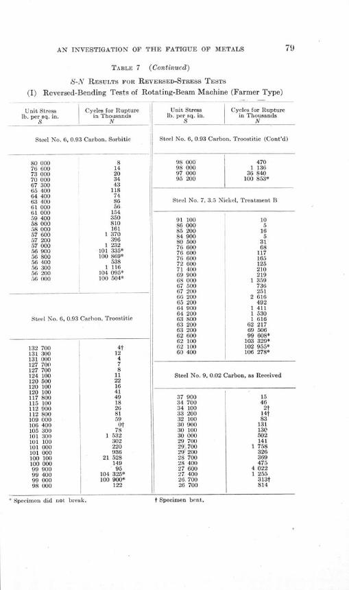
AN INVESTIGATION OF THE FATIGUE OF METALS
TABLE 7 (Continued)
S-N RESULTS FOR REVERSED-STRESS TESTS
(I) Reversed-Bending Tests of Rotating-Beam Machine (Farmer Type)
Unit Stress Cycles for Rupture Unit Stress Cycles for Rupturelb. per sq. in. in Thousands lb. per sq. in. in Thousands
S I N S N
Steel No. 6, 0.93 Carbon, Sorbitic Steel No. 6, 0.93 Carbon, Troostitic (Cont'd)
80 000 8 98 000 47076 600 14 98 000 1 13673 000 20 97 000 36 84070 000 34 95 200 100 853*67 300 4365 400 11864 400 7463 400 86 Steel No. 7, 3.5 Nickel, Treatment B61 000 5661 000 15459 400 350 91 100 1058 000 810 86 000 558 000 161 85 200 16
57 200 39657 000 1 23256 900 101 335*56 800 100 869*56 400 53856 300 1 11656 200 104 095*56 000 100 504*
Steel No. 6, 0.93 Carbon, Troostitic
132 700 4t131 300 i 12131 000 4127 700 . 7127 700 8124 100 11120 500 22120 100 16120 100 41117 800 49115 100 18112 900 26112 800 81109 000 59106 400 Of105 300 78101 300 1 532101 100 302101 000 220101 000 936100 100 21 528100 000 14999 900 9599 400 104 325*99 000 100 900*98 000 122
84 900 580 500 3176 600 6876 600 11776 600 16572 600 12571 400 21069 900 21968 000 1 35967 500 73667 200 25166 200 2 61665 200 49264 900 1 41164 200 1 53063 800 1 61663 200 62 21763 200 69 50662 600 99 608*62 100 103 329*62 100 102 955*60 400 106 278*
Steel No. 9, 0.02 Carbon, as Received
37 90034 70034 10033 20032 10030 90030 10030 00029 70029 70029, 20028 70028 40027 60027 40026, 70026 700
15462t14t83
131130502141
1 758326369475
4 0221 255
313?814
* Specimen did not break. t Specimen bent.

80 ILLINOIS ENGINEERING EXPERIMENT STATION
TABLE 7 (Continued)
S-N RESULTS FOR REVERSED-STRESS TESTS
(I) Reversed-Bending Tests of Rotating-Beam Machine (Farmer Type)
Unit Stress Cycles for Rupture Unit Stress Cycles for Rupturelb. per sq. in. in Thousands lb. per sq. in. in Thousands
S N S N
Steel No. 9, 0.02 Carbon, as Received (Cont'd) Steel No. 9, 0.02 Carbon, Square Shoulder
26 200 2f 23 300 Of26 200 944 22 000 Ot26 200 1 869 20 000 40826 100 104 506* 18 600 416t26 000 1 392 18 200 35t25 900 4 251 18 100 4 91225 900 100 576* 18 100 10 774*25 400 104 871* 17 100 1 55125 100 104 175* 16 000 914
15 500 1 01915 500 8 89114 800 47014 700 43414 200 295t
Steel No. 9, 0.02 Carbon, Rough Turned 13 600 1 49213 600 12 828*13 600 12 234*13 400 10 000*13 700 10 077*
32 300 3129 700 10429 200 11027 900 40627 900 45327 200 57625 900 6 32925 600 2 29125 000 434t24 900 5 42424 600 40724 100 578t24 000 4 83623 100 11 372*
Steel No. 9, 0.02 Carbon, Smooth Turned
33 500 4t32 300 4530 300 23627 900 80625 900 1 48025 400 2 75624 900 2 042t24 400 7 78124 400 10 880*24 000 899t24 000 25 936*23 600 2 325t23 600 12 256*23 500 21 937*
* Specimen did not break.
Steel No. 9, 0.02 Carbon, 1" Radius
34 000 8732 300 4T28 700 14t27 800 39327 000 22t26 000 1 41825 800 1 11625 300 1 61524 500 46t24 000 4 64624 000 13 486*23 800 1 62523 300 3 25122 800 4 37822 300 173f22 200 15 129*22 000 2 06222 000 39 129*
Steel No. 10, 0.49 Carbon, Sorbitic
64 500 2t64 400 18t62 000 5t60 300 52t60 000 3859 900 35
t Specimen bent.

AN INVESTIGATION OF THE FATIGUE OF METALS 81
TABLE 7 (Continued)
S-N RESULTS FOR REVERSED-STRESS TESTS
(I) Reversed-Bending Tests of Rotating-Beam Machine (Farmer Type)
Unit Stresss Cycles for Rupturelb. per sq. in. in Thousands
S N
Steel No. 10, 0.49 Carbon, Sorbitic (Cont'd)
57 70056 00056 00055 30054 10053 10051 80050 80050 80050 50050 50050 30049 50049 00049 00048 80048 50048 00047 80047 100
10116148t
43232t
229514793584315
101 099*101 934*
568167766580252
100 940*106 282*106 235*
Unit Stresslb. per sq. in.
S
Cycles for Rupturein Thousands
N
Steel No. 10, 0.49 Carbon, Sorbitic,Ground Finish
59 60056 20053 80052 10050 80049 00048 30047 10046 00045 70045 90045 30042 200
266940
155102499357260
2 7762 615
19210 266*8 691*
Steel No. 10, 0.49 Carbon, Sorbitic,Rouge Finish
Steel No. 10, 0.49 Carbon, Sorbitic,Rough Turned
57 90055 40050 50047 40044 60042 20041 80041 40041 30040 800
216872
154274430417744
15 156*11 167*
Steel No. 10, 0.49 Carbon, Sorbitic,Smooth Turned
56 00055 70053 70051 40050 30049 90048 00047 90046 00045 50044 60044 10043 90043 60042 700
* Specimen did not break.
1369
104523169265111201232
11 223*534554
1 66610 647*13 534*
64 80057 60055 10053 50052 10051 80051 10050 70050 70050 70050 40050 000
2t230230
2 203494354721243
12 603*727246
14 532*
Steel No. 10, 0.49 Carbon, Sorbitic,Square Shoulder
46 000 5039 700 11234 000 20433 700 17429 300 55127 400 1 72926 500 65025 900 4 72625 800 2 16125 400 90825 300 86225 000 53024 600 95024 300 48 290*24 000 1 54324 000 98723 800 2 42823 500 10 734*23 300 13 131*
t Specimen bent.

ILLINOIS ENGINEERING EXPERIMENT STATION
TABLE 7- (Continued)
S-N RESULTS FOR REVERSED-STRESS TESTS
(I) Reversed-Bending Tests of Rotating-Beam Machine (Farmer Type)
Unit Stress Cycles for Rupturelb. per sq. in. in Thousands
SN
Steel No. 10, 0.49 Carbon, Sorbitic, V-Notch
40 00039 50034 90030 90028 20026 00023 70021 90019 40019 20019 10019 00018 80018 80018 00016 900
15476
110228331441431670459
3 393
21 800*887
12 480*17 634*10 090*
Steel No. 10, 0.49 Carbon, Sorbitic, M" Radius
65 400 2660 100 4954 500 11750 800 80050 700 39849 400 99149 00048 60048 20047 60047 50047 00046 10045 10044 10044 000
1 298427582618361882926
1 41610 639*15 072*
Steel No. 10, 0.49 Carbon, Sorbitic, 1" Radius
66 90064 00059 80056 80054 30053 50050 10050 00049 50049 100
174360
168117220505452195
10 086*
Unit Stress Cycles for Rupturelb. per sq. in. in Thousands
S N
Steel No. 10, 0.49 Carbon, Sorbitic, 1" Radius(Cont'd)
49 00048 50048 10048 00047 50047 500
896521
12 793*12 669*1 11010 223*
Steel No. 10, 0.49 Carbon, Sorbitic, 38% Over-stress, N =100, S =69 700
67 00065 70064 70062 50061 10057 90056 40054 30052 60051 10050 80050 50050 00049 500
2f3?
577514436t21245
3371 000
10 220*398
14 440*10 687*
Steel No. 10, 0.49 Carbon, Sorbitic, 35% Over-stress, N=1000, S=65 000
56 60053 70052 40051 80050 00049 80049 00048 60047 20046 50045 90045 80045 600
8st57224274
1 162294352426328819
2t20 986*
147
Steel No. 10, 0.49 Carbon, Sorbitic, 29% Over-stress, N = 1000, S=62 000
60 00055 00052 90051 10050 800
* Specimen did not break. t Specimen bent,

AN INVESTIGATION OF THE FATIGUE OF METALS
TABLE 7 (Continued)
S-N RESULTS FOR REVERSED-STRESS TESTS
(I) Reversed-Bending Tests of Rotating-Beam Machine (Farmer Type)
Unit Stress Cycles for Rupturelb. per sq. in. in Thousands
S N
Steel No. 10, 0.49 Carbon, Sorbitic,29% Overstress, N =1000, S =62 000 (Cont'd)
50 300 39249 500 23649 300 2 43049 000 3 27948 400 10 140*47 800 34047 800 650
Steel No. 10, 0.49 Carbon, Sorbitic,29% Overstress, N =5000, S =62 000
54 00050 00048 80047 20046 50046 00044 90044 10043 10043 10042 90042 70042 30041 800
2810018329t90
221234
1 09110 738*
514238433
10 057*10 620*
Steel No. 10, 0.49 Carbon, Sorbitic,20% Overstress, N=5000, S=60 600
58 500 8455 000 38352 900 68451 300 1 22050 500 2 88349 800 10 022*
Steel No. 10, 0.49 Carbon, Sorbitic,10% Overstress, N =5000, S =55 600
54 30053 10052 10050 50050 50050 500
116662643510
1 22010 554*
Unit Stress Cycles for Rupturelb. per sq. in. in Thousands
S N
Steel No. 50, Cold-drawn, as Received
70 00060 30055 60050 30045 00042 20041 10040 70040 40040 30040 00040 00036 200
697108397
1 0732 2841 958
56 976*3 4808 919
74 956*51 376*57 606*
Steel No. 50, Cold-drawn, Annealed at 13000 F.
41 200 1840 800 1935 000 14733 500 8431 600 45730 500 68029 700 35629 000 81828 900 61 754*27 900 59 628*25 600 5 289t25 000 3 229
No. 50, Cold-drawn, Annealed at 1550° F.
94 70NN
33 400- 32 50031 20029 50028 90028 20026 90025 100
25248571
2 0421 0992 0591 3803 371
52 244*
* Specimen did not break. t Specimen bent.
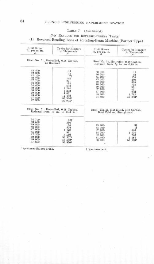
LI LINOIS
EN
--.... - INEE rING EXPERIMENT STATION
TABLE 7 (Continued)
S-N RESULTS FOR REVERSED-STRESS TESTS
(I) Reversed-Bending Tests of Rotating-Beam Machine (Farmer Type)
Unit Stress Cycles for Rupture Unit Stress Cycles for Rupturelb. per sq. in. in Thousands lb. per sq. in. in ThousandsIV N SI N
Steel No. 51, Hot-rolled, 0.18 Carbon,as Received
45 40042 30042 10039 70037 70036 20034 60030 30030 30029 20028 60027 80027 300
24337t
148221172602
1 2441 2924 631
12 45253 926*50 905*
Steel No. 51, Hot-rolled, 0.18 Carbon,Reduced from V in. to 0.44 in.
54 700 32f50 500 23049 800 5548 300 52447 000 1 17845 200 91142 200 3 51940 000 53 537*40 000 53 582*37 600 53 826*
Steel No. 51, Hot-rolled, 0.18 Carbon,Reduced from Y2 in. to 0.48 in.
50 10046 70045 20043 10040 00040 00039 00037 70037 00035 80034 800
2542
154260385795841671203
1 71252 383*
Steel No. 51, Hot-rolled, 0.18 Carbon,Bent Cold and Straightened
49 80045 30037 30034 70032 50031.40030 000
5461 504
7262 384
65 198*
Specimen did not break. Specimen bent.t Specimen bent,* Specimen did not break.
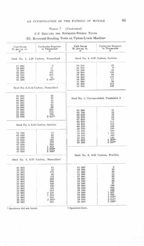
AN INVESTIGATION OF THE FATIGUE OF METALS
TABLE 7 (Continued)
S-N RESULTS FOR REVERSED-STRESS TESTS
(II) Reversed-Bending Tests on Upton-Lewis Machine
Unit Stresslb. per sq. in.
S
Cycles for Rupturein Thousands
N
Steel No. 1, 1.20 Carbon, Normalized
65 000 660 000 1158 400 2348 600 16746 700 49545 000 8144 200 2 047*
Steel No. 3, 0.52 Carbon, Normalized
Unit Stresslb. per sq. in.
S
Cycles for Rupturein Thousands
N
Steel No. 4, 0.37 Carbon, Sorbitic
70 70066 70064 30058 90057 80054 80054 20051 60044 80044 700
53 300 2046 500 2646 000 4043 300 7941 200 9538 000 9837 000 22534 200 31533 000 19532 000 2 017*
Steel No. 3, 0.52 Carbon, Sorbitic
70 700 15an ann4AC
54 00050 00048 00047 00045 00043 00042 000
93143179392
1 3232 086*2 928*
Steel No. 4, 0.37 Carbon, Normalized
45 00040 00038 20038 00036 00036 00035 90034 80034 00032 80032 00032 00031 20031 00030 20030 000
1349
17896
113248289429446196214
2 2261 224
3302 007*
895
Steel No. 5, Chrome-nickel, Treatment A
95 20085 10080 00069 30067 80064 80064 40060 10059 70055 10054 20054 10053 20051 60050 200
3152426478111413558340406
1 182469444
2 307*2 017*
Steel No. 6, 0.93 Carbon, Pearlitic
45 60043 30041 90041 00037 80035 80033 70032 00030 80030 00029 20028 90028 90028 60028 00028 600
* Specimen did not break,
819263530788997190393228
1 0271 5822 018*2 011*2 359*
t Specimen bent,
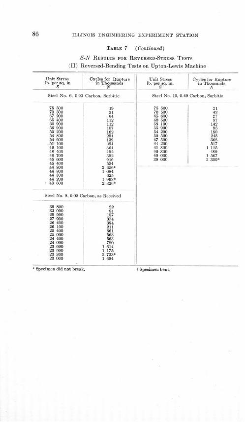
ILLINOIS ENGINEERING EXPERIMENT STATION
TABLE 7 (Continued)
S-N RESULTS FOR REVERSED-STRESS TESTS
(II) Reversed-Bending Tests on Upton-Lewis Machine
Unit Stress Cycles for Rupturelb. per sq. in in Thousands
S N
Steel No. 6, 0.93 Carbon, Sorbitic
75 500 1970 500 3167 200 6465 400 11260 900 11256 900 10755 200 16254 800 29454 600 13951 100 29449 100 36448 400 49246 700 39245 600 91645 400 52444 800 2 656*44 800 1 08444 300 62544 200 1 993*43 600 2 326*
Steel No. 9, 0.02 Carbon, as Received
39 800 2232 000 8129 900 18727 900 37426 400 39426 100 21125 400 66125 000 56324 400 56324 000 78023 600 1 61423 600 1 17523 300 2 723*23 000 1 694
Unit Stresslb. per sq. in.
__S
Steel No. 10,
75 50070 50065 60060 50058 10055 90054 20050 50047 50044 20041 80040 30040 00039 000
Cycles for Rupturein Thousands
N
0.49 Carbon, Sorbitic
21432737
14295
180245368517
1 115489
1 5672 309*
* Specimen did not break. f Specimen bent.
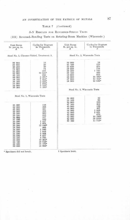
A~T IMVVCPIaA'rTOM OF TI-iF FATIOTTE OF METALS
TABLE 7 (Continued)
S-N RESULTS FOR REVERSED-STRESS TESTS
(III) Reversed-Bending Tests on Rotating-Beam Machine (Wisconsin)
Unit Stress Cycles for Rupture Unit Stress Cycles for Rupturelb. per sq. in. in Thousands lb. per sq. in. in Thousands
S N S N
Steel No. 5, Chrome-Nickel, Treatment A. Steel No. 2, Wisconsin Tests
99 900 14 50 000 5489 900 26 45 100 22280 200 49 42 600 47672 800 74 39 900 75865 200 224 39 500 1 78362 000 10 623* 39 100 45060 100 216 39 000 90360 000 5 231* 38 000 10 486*58 100 7 215* 37 000 12 102*56 100 5 222* 34 900 12 642*54 000 7 250*52 000 5 122*50 300 5 193*
Steel No. 3, Wisconsin Tests
Steel No. 1, Wisconsin Tests59 600 4253 100 9650 000 180
45 000 118 47 500 403
42 000 238 45 000 539
39 900 331 44 900 467
39 900 164 44 000 5 828
39 000 600 43 000 3 031
39 000 415 43 000 670
38 600 517 42 000 10 549*
37 000 630 42 000 20 833*
36 000 1 317 42 100 15 716*
36 000 1 07635 200 12 446*34 900 80634 900 1 94034 000 1 91634 000 3 60834 000 4 85733 500 4 79033 500 10 662*33 100 10 759*32 500 14 173*30 000 14 984*
* f Specimen bent.pecimen did not break.
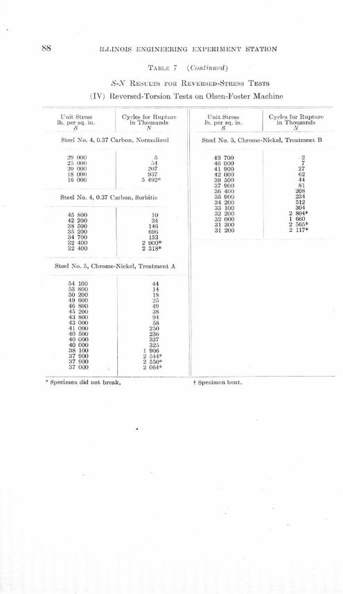
ILLINOIS ENGINEERING EXPERIMENT STATION
TABLE 7 (Continucd)
S-N RESULTS FOR REVERSED-STRESS TESTS
(IV) Reversed-Torsion Tests on Olsen-Foster Machine
Unit Stress Cycles for Rupturelb. per sq. in. in Thousands
S N
Steel No. 4, 0.37 Carbon, Normalized
29 000 525 000 5420 000 20718 000 93716 000 5 492*
Steel No. 4, 0.37 Carbon, Sorbitic
45 800 1042 200 3438 500 14635 200 69634 700 15332 400 2 000*32 400 2 318*
Steel No. 5, Chrome-Nickel, Treatment A
54 100 4453 800 1450 200 1849 600 2546 800 4945 200 3843 800 9443 000 5841 000 25040 500 23640 000 33740 000 32538 100 1 90637 900 2 544*37 900 2 550*37 000 2 064*
Specimen did not break.
Unit Stress Cycles for Rupturelb. per sq. in. in Thousands
S N
Steel No. 5, Chrome-Nickel, Treatment B
49 700 246 000 741 900 2742 000 6239 500 4437 900 8136 400 20835 900 23434 200 51233 100 30432 200 2 804*32 000 1 66031 300 2 565*31 200 2 117*
t Specimen bent.

AN INVESTIGATION OF THE FATIGUE OF METALS 89
TABLE 7 (Continued)
S-N RESULTS FOR REVERSED-STRESS TESTS
(IV) Reversed-Torsion Tests on Olsn-Foster Machine
Unit Stress Cycles for Rupture Unit Stress Cycles for Rupturelb. per sq. in. in Thousands lb. per sq. in. in Thousands
S N S , N
Steel No. 6, 0.93 Carbon, Pearlitic Steel No. 9, 0.02 Carbon, as Received
26 000 7 20 000 1325 000 18 18 000 3524 000 52 17 300 3422 000 87 16 000 8221 000 147 14 900 15720 000 79 14 300 17820 000 196 13 500 42019 800 305 13 200 78019 000 509 13 000 1 50518 000 703 12 700 2 446*17 500 1 149 12 500 1 63217 000 1 742 12 400 2 062*16 800 1 92616 500 2 000*16 100 2 880*
Steel No. 10, 0.49 Carbon, Sorbitic
Steel No. 6, 0.93 Carbon, Troostitic34 000 931 600 3429 200 82
77 500 4 26 900 26668 600 4 25 600 2 206*65 500 3765 200 21564 200 2759 500 7457 700 1157 200 17354 800 38953 500 68553 200 22053 100 41852 500 2 039*52 400 2 045*52 100 2 198*51 400 1 059
* Specimen did not break. t Specimen bent.

ILLINOIS ENGINEERING EXPERIMENT STATION
IV. DISCUSSION OF RESULTS
14. Endurance Limit.-The question whether any material can
withstand an infinite number of repetitions of stress, however small,cannot of course be answered by direct experimentation. Earlier
investigators determined a "limit" from plotted curves with values
of unit stresses as ordinates, and numbers of repetitions of stress
causing failure as abscissas. Denoting values of unit stress by S
and number of cycles of stress necessary to cause failure by N, such
diagrams may be conveniently designated as S-N diagrams, and are
so designated in this bulletin. Having drawn such a diagram, the
early experimenters then judged as best they could where the S-Ndiagram became horizontal, and took the S ordinate corresponding tothis horizontal asymptote as the limiting stress which could be with-stood an indefinite number of times. Fig. 36 (A) shows some of thetest data of this investigation plotted in this way. A careful read-ing of the writings of early investigators shows that they recognizedthe limitations of this method and the enormous extrapolation in-volved.
A modification of this method is to plot values of S as ordinatesand values of the reciprocal of N as abscissas. (See Fig. 36 [B] inwhich some of the test data of this investigation are thus plotted).Then the limit for indefinite repetition of stress is found by extend-ing the curve backward until it crosses the zero line of abscissas.This method involves an extrapolation which apparently is onlyslight, but which in reality is as great as that involved in the firstmethod. In Fig. 36(B) the horizontal distance between A, cor-responding to the smallest observed value of 1/N, and the zero linefor 1/N seems small, but in reality it corresponds to an infinite dis-tance along the N-axis in the S-N diagram, Fig. 36 (A). This methodof plotting gives no assurance that the reciprocal S-N diagrams donot follow the broken lines in Fig. 36(B).
A modification of this second method, suggested by Mr. C. E.Stromeyer of Manchester, England, involves plotting values of S
1against values of -/. This method gives a graph which is nearly

AN INVESTIGATION OF THE FATIGUE OF METALS
(Al6000 0--\ii
CCS a------ - - 093-carbon sorb#/c
° ^ •05£ corbon norma//'zed
4000 -0--I----i--i---
2400000t-----oj---2C000/000 rt o000/000 Cycles for Rulvture, (/V/
(C) II-; 093 carbon, sor6///c -
tY~~cls 2 carha-~.,,orna
002 carbon
/00000
I UUU
60000
50000
1 9CIUUL'
KtO
CUUU./.60 /00 /000 /0000
/000 Cycles for Ruplure, (NV/FIG. 36. VARIOUS METTIODS OF PLOTTING S-N DIAGRAMS
I
F
514
I i

ILLINOIS ENGINEERING EXPERIMENT STATION
a straight line, but involves the same extrapolation as does the methodgiven above.
Some later authorities, including Professor Basquin of North-western University, and, later, Moore and Seely, have suggested thatthe relation between S and N may be expressed by an equation of
Bthe form S= (N), in which B and K are experimentally determined
constants. This viewpoint has been advocated as being a safe view-point for designers, rather than as an exact statement of relation, andit involves the assumption that any stress repeated often enoughwill eventually cause failure of a material. If, in place of plottingvalues of S and N, values of log S and log N are plotted, or valuesof S and N are plotted on logarithmic croý.s-section paper, the rela-tion given in the above'equation is represented by a straight line.
In Fig. 36(C) the results of some tests of this investigation areplotted to logarithmic co6rdinates. In this figure, as in all the S-Ndiagrams plotted to logarithmic co6rdinates, the plotted point forany specimen which was not broken is marked with an arrow. Itmay be noted that logarithmic plotting enables both small valuesand large values of N to be plotted with a reasonable degree ofaccuracy. It should be noted that Fig. 36(A), Fig. 36(B), andFig. 36(C) show the same test data plotted in different ways. Thediagrams of Fig. 36 (C) indicate that up to a certain value of N apower equation is followed fairly closely, but then there comes aquite decided break in the graph, after which a horizontal line seemsto represent the relation between S and N up to the value of N of100 000 000, with no indication of a further break in the diagram.On a logarithmic S-N diagram, as on an ordinary S-N diagram, ahorizontal line would seem to indicate that a limit for indefinite re-versals of stress had been reached, and the ordinate of such a linegives a value of S which in this bulletin is designated as the " en-durance limit."
It is of course possible that the relation between S and N is ofsuch a nature that at some point beyond 100 000 000 reversals thediagram again slopes downward. However, it is believed that theseexperiments have been of sufficient extent and sufficiently numerousto justify regarding the unit stress corresponding to the horizontalline as a unit stress which can be completely reversed for an in-
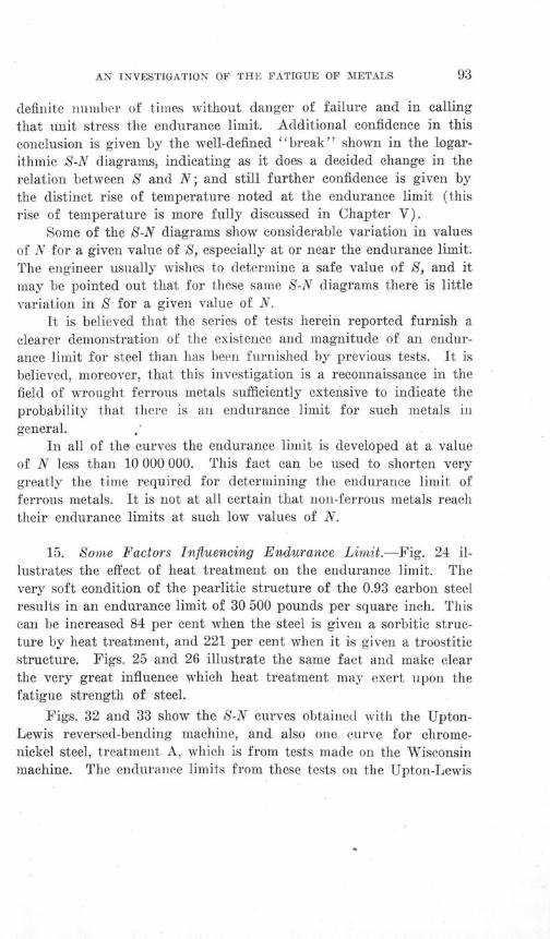
AN INVESTIGATION OF THE FATIGUE OF METALS
definite number of times without danger of failure and in calling
that unit stress the endurance limit. Additional confidence in this
conclusion is given by the well-defined "break" shown in the logar-
ithmic S-N diagrams, indicating as it does a decided change in the
relation between S and N; and still further confidence is given by
the distinct rise of temperature noted at the endurance limit (this
rise of temperature is more fully discussed in Chapter V).
Some of the S-N diagrams show considerable variation in values
of N for a given value of 8, especially at or near the endurance limit.
The engineer usually wishes to determine a safe value of 8, and it
may be pointed out that for these same S-N diagrams there is little
variation in S for a given value of N.
It is believed that the series of tests herein reported furnish a
clearer demonstration of the existence and magnitude of an endur-
ance limit for steel than has been furnished by previous tests. It is
believed, moreover, that this investigation is a reconnaissance in the
field of wrought ferrous metals sufficiently extensive to indicate the
probability that there is an endurance limit for such metals in
general.In all of the curves the endurance limit is developed at a value
of N less than 10 000 000. This fact can be used to shorten verygreatly the time required for determining the endurance limit offerrous metals. It is not at all certain that non-ferrous metals reachtheir endurance limits at such low values of N.
15. Some Factors Influencing Endurance Limit.-Fig. 24 il-
lustrates the effect of heat treatment on the endurance limit. The
very soft condition of the pearlitic structure of the 0.93 carbon steelresults in an endurance limit of 30 500 pounds per square inch. Thiscan be increased 84 per cent when the steel is given a sorbitic struc-ture by heat treatment, and 221 per cent when it is given a troostiticstructure. Figs. 25 and 26 illustrate the same fact and make clearthe very great influence which heat treatment may exert upon thefatigue strength of steel.
Figs. 32 and 33 show the S-N curves obtained with the Upton-Lewis reversed-bending machine, and also one curve for chrome-nickel steel, treatment A, which is from tests made on the Wisconsinmachine. The endurance limits from these tests on the Upton-Lewis
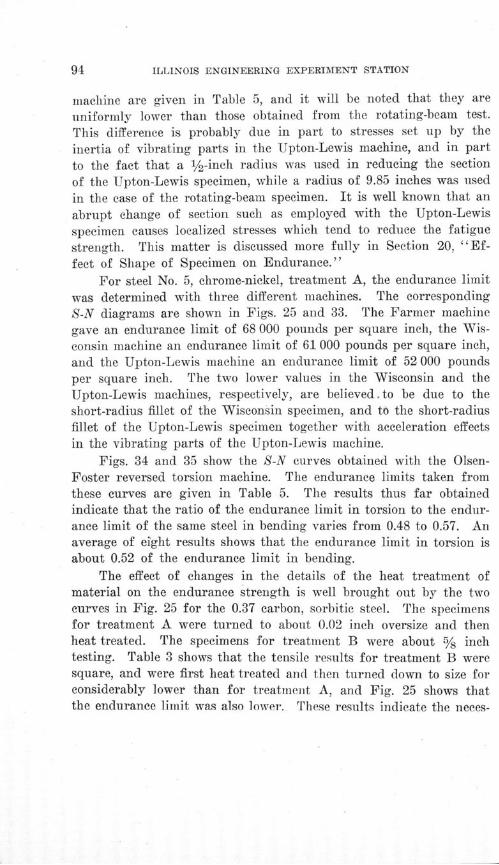
ILLINOIS ENGINEERING EXPERIMENT STATION
machine are given in Table 5, and it will be noted that they are
uniformly lower than those obtained from the rotating-beam test.
This difference is probably due in part to stresses set up by theinertia of vibrating parts in the Upton-Lewis machine, and in partto the fact that a ½1/-inch radius was used in reducing the sectionof the Upton-Lewis specimen, while a radius of 9.85 inches was usedin the case of the rotating-beam specimen. It is well known that anabrupt change of section such as employed with the Upton-Lewisspecimen causes localized stresses which tend to reduce the fatiguestrength. This matter is discussed more fully in Section 20, "Ef-fect of Shape of Specimen on Endurance."
For steel No. 5, chrome-nickel, treatment A, the endurance limitwas determined with three different machines. The correspondingS-N diagrams are shown in Figs. 25 and 33. The Farmer machinegave an endurance limit of 68 000 pounds per square inch, the Wis-consin machine an endurance limit of 61 000 pounds per square inch,and the Upton-Lewis machine an endurance limit of 52 000 poundsper square inch. The two lower values in the Wisconsin and theUpton-Lewis machines, respectively, are believed. to be due to theshort-radius fillet of the Wisconsin specimen, and to the short-radiusfillet of the Upton-Lewis specimen together with acceleration effectsin the vibrating parts of the Upton-Lewis machine.
Figs. 34 and 35 show the S-N curves obtained with the Olsen-Foster reversed torsion machine. The endurance limits taken fromthese curves are given in Table 5. The results thus far obtainedindicate that the ratio of the endurance limit in torsion to the endur-ance limit of the same steel in bending varies from 0.48 to 0.57. Anaverage of eight results shows that the endurance limit in torsion isabout 0.52 of the endurance limit in bending.
The effect of changes in the details of the heat treatment ofmaterial on the endurance strength is well brought out by the twocurves in Fig. 25 for the 0.37 carbon, sorbitic steel. The specimensfor treatment A were turned to about 0.02 inch oversize and thenheat treated. The specimens for treatment B were about % inchtesting. Table 3 shows that the tensile results for treatment B weresquare, and were first heat treated and then turned down to size forconsiderably lower than for treatment A, and Fig. 25 shows thatthe endurance limit was also lower. These results indicate the neces-
AN INVESTIGATION OF THE FATIGUE OF METALS
sity of having the conditions of heat treating as nearly the same as
possible in order to get uniform results.
In those cases in which specimens from the same steel were
tested in a normalized and in a sorbitic condition, the S-N curves
show that the endurance limit is higher for the sorbitic condition
by 31 per cent for the 0.52 carbon, 73 per cent for the 0.37 carbon,
and 84 per cent for the 1.20 carbon steel. For the 0.93 carbon, the
sorbitic gives an endurance limit 84 per cent higher than the pear-
litic steel.
An interesting fact, shown by Table 3, is that the 0.37 carbon
sorbitic steel has a percentage of elongation almost as high as the
0.37 carbon normalized steel, and the percentage of reduction of area
is even higher. For the 0.93 carbon steel the ductility is almost
exactly the same for the sorbitic specimens as for the pearlitic; for
the 0.52 carbon steel the elongation is slightly less for the sorbitic
specimens than for the normalized, but the reduction of area is
greater; while for the 1.20 carbon steel the sorbitic condition has
actually a higher ductility than the normalized. These results in-
dicate that heat treatment may greatly improve the static and fatigue
strength properties of the material with no serious sacrifice of duc-tility.
The tests were not conducted with the intention of comparing
carbon steels with nickel and chrome-nickel steels, but certain qualiti-tative results may be mentioned. Table 3 shows that the sorbitic
treatment for the carbon steels, with the one exception of the 1.20carbon steel, develops about the same ductility represented by per-centage of elongation as the heat treatments which were used forthe nickel and chrome-nickel steels. The results indicate that thenickel and chrome-nickel steels have the advantage of somewhathigher endurance limits for the same ductility. This result is notunexpected, judging from the well-known fact that these alloy steelsin comparison with carbon steels show high ductility for a givenstatic strength.
16. Relation of Static Strength to Endurance Limit.-The testsdescribed in this bulletin seem to indicate that the results of statictests made in an ordinary testing machine are not reliable as anindex of the strength of the material under reversed stress as de-

ILLINOIS ENGINEERING EXPERIMENT STATION
termined by the rotating-beam test. In confirmation of this, atten-tion is called to Fig. 37, in which are plotted values of the endurancelimit, the proportional limit, and the ultimate tensile strength for
• u - /,"/a' ql/ ", e ,/ow/i,7 eueZ
u!/ , V, ,-,/ (-W-,•i. '•,-.,, d// ./'uf / 11 .. u•./.puR.9•ul *sý Jv'ql '41//W17 -14/5-0/_7 o./odc/
z
Iit
fi-
ZE
el= z
zz
0aF-
I
0
0
z <a , , n_ o , .. y r, uU .. *£.£^ C/£f ... a. .,, .... . •. .... ... .S... ^/._" ........... r

AN INVESTIGATION OF THE FATIGUE OF METALS
the various steels tested, arranged in such order that the endurance
limits increase from left to right. The values for proportional limit
do not follow at all closely the values for endurance limit. Compu-
tatiofis from the values given in this figure show that the ratio of
endurance limit to proportional limit varies from 1.5 to 0.5, making
it apparent that the proportional limit cannot be used to predict
fatigue strength in bending. The variation in the ratio of endur-
ance limit to ultimate tensile strength is not as great as the variation
just mentioned, but is considerable, the ratio ranging from 0.68 to
0.36. In general as the proportional limit and the ultimate tensile
strength increase the endurance limit also increases.Fig. 37 also shows values of the endurance limit as determined
by a temperature test, which is discussed in detail in Chapter V.A study of the endurance limits in torsion and the correspond-
ing proportional limits shows that here also the proportional elasticlimit is not a reliable index of fatigue strength. In this case, theratio of endurance limit to the proportional elastic limit was foundto range from a value of 1 for the 0.02 carbon steel and the 0.93carbon pearlitic steel, to 0.51 for the chrome-nickel steel, treatment A.
The determination of the elastic limit and the ultimate strength(Fig. 37) depends upon the average properties of a considerablemass of material. A minute defect, such as a nick on the surface,an incipient crack in the structure, or a localized stress resultingfrom heat treatment, will not in general affect the determinationto an appreciable extent. On the other hand, such a localized defectmay readily act as a nucleus for structural damage which, under re-peated stress, spreads in the form of minute cracks with continuedlocalized stress present at the roots of these cracks, and finally causesfailure.
It is readily conceivable that even for a material free from seri-ous flaws non-homogeneity of structure might affect resistance torepeated stress to a much greater extent than it does static strength.Consider two materials, A, made up of strong and weak crystalswith a large preponderance of strong crystals, and B, made up ofcrystals all alike, and all somewhat weaker than the strong crystalsof A. It seems quite possible that material A will give higher elasticstrength under static tests and lower strength under repeated stressthan material B. Such might well be the case for the chrome-nickel
ILLINOIS ENGINEERING EXPERIMENT STATION
steel with heat treatment A as compared with the troostitic 0.93carbon steel, the former corresponding to material A, and the latterto material B.
Fig. 25, which shows the S-N curves for the three heat treatmentsof steel No. 5, chrome-nickel, is especially interesting. By referringto Table 3 it will be seen that treatment A gives the highest ultimatestrength and proportional elastic limit; treatment B is about 15 percent lower, yet the endurance limit is almost as high as with treat-ment A. Treatment C gives a low proportional elastic limit com-pared with the other two treatments, yet the endurance limit isactually a little higher than that for treatment B and almost ashigh as that for treatment A. This is particularly interesting inview of the fact that the proportional elastic limit of material withtreatment C is low compared with its yield point, and that thetension stress-deformation curve shows considerable permanent setbelow the yield point. On the basis of mechanical hysteresis itwould ordinarily be expected that a material which showed consider-able permanent set would probably be poor in resisting fatigue. Thisdoes not seem to be the case for treatment C of the chrome-nickelas compared with the other two treatments.
One rather remarkable result is indicated by Fig. 37. Com-putation from values given in the figure shows that the ratio of thecomputed stresses at the endurance limit to the proportional elasticlimit of the 0.02 carbon steel was almost 1.5, and the endurance limitwas actually 33 per cent higher than the average yield point in ten-sion and compression. This result may at first appear impossible,and it is believed that it would be impossible in reversals of directtensile and direct compressive stress, but it must be recalled thatthe endurance limit here mentioned was obtained from a rotating-beam test. Evidently the inner fibers of the beam, which are notstressed as highly as those on the outside surface, reinforce the outerfibers sufficiently so that the nominal stress calculated is actuallyhigher than the yield point of the material. Of course the outerfibers are actually stressed only to the yield point, but evidentlyenough of the inner fibres are sufficiently stressed so that the resist-ing moment of the beam is increased to about 33 per cent above thatbased upon the yield point. While the above is an explanation ofthe possibility of the result it does not make the result less remark-
AN INVESTIGATION OF THE FATIGUE OF METALS
able, especially in view of the fact that only one other steel, the 0.93
carbon, gave an endurance limit even approximately equal to the
proportional elastic limit of the material, as is clearly shown in
Fig. 37. This result is called remarkable not because of the high
endurance limit developed (the endurance limit of the 0.02 carbon
steel was the lowest of all the steels tested) but merely because of
the high ratio of endurance limit to proportional elastic limit and
to yield point, and because it is believed that so high a ratio has not
been observed before.It seems clear that, in any case, the endurance limit for steel
can be no higher than its yield point. That is to say, the actual unit
stress existing in fatigue is limited to the yield point, although the
nominal calculated stress, as in the case of the 0.02 carbon steel,
may sometimes be higher than the yield point.
This matter has been dwelt upon at length because it may offer
a clue to a quality necessary in a steel to produce a high ratio of
endurance limit to proportional elastic limit. Apparently the only
quality possessed by the 0.02 carbon steel which offers an adequate
explanation of the above phenomenon was its great homogeneity.
This steel was almost pure ferrite, while all the other steels were
made up of several constituents. The only other steel which showed
an endurance limit higher than the proportional elastic limit was
the 0.93 carbon pearlitic steel. When the steel is made up all of
pearlite or all of ferrite the ratio of endurance limit to proportionalelastic limit is high. It seems to the writers that perhaps one ofthe qualities to be desired in order to get a high ratio of endurancelimit to proportional elastic limit may be homogeneity of structure.
From the test data given in Appendix A it appears that anneal-ing various grades of steel gives a high ratio of endurance limit toproportional limit. It would seem reasonable that either homogene-ity of metallographic structure or freedom from internal strains(such freedom as would be brought about by thorough annealing)should tend to give a high ratio of endurance limit to proportionallimit.
It does not seem likely that ductility, as shown by percentageof reduction of area and by percentage of elongation, will have muchbearing on the strength in fatigue. These quantities are based uponthe action of a bar as a whole and in ductile materials are largely

ILLINOIS ENGINEERING EXPERIMENT STATION
dependent upon the final necking down after the ultimate has beenreached. In fatigue failures there is no necking down, but the ma-
terial fails as though it were brittle. Furthermore, the action in
fatigue is extremely local and does not involve a large portion of
the bar. A study of Table 3 will show the basis for the foregoing
statements. The 0.93 carbon troostitic steel, for instance, shows low
elongation and reduction of area, but a high endurance limit and a
high ratio of endurance limit to proportional elastic limit.
It has been suggested by various investigators that the use of
very delicate instruments for measuring deformation might enablean experimenter to detect in a static test the minute fractures whichare supposed to occur at the endurance limit. An apparatus ofgreat delicacy has been developed by Mr. W. J. Francke of NewBrunswick, New Jersey,* who has tested in his laboratory specimensof several of the steels studied in this investigation. The resultsin Table 5 showing the "FR" point determined in the Franeke testindicate that the stress corresponding to this "FR" point coincidesquite closely with the endurance limit in some cases, but not sowell in others. More information will be necessary to determinethe value of the Francke test as a criterion of fatigue strength.
17. Correlation of Results of Hardness Tests and of ImpactTests With Results of Reversed-Stress Tests.-The results of theCharpy impact-bending tests, the Charpy impact-tension tests, andthe repeated-impact tests indicate that the results of the impact testsmade cannot be used as a criterion of fatigue strength. Fig. 38,in which the plan of plotting results is similar to that used in Fig.37, makes this clear. The results of these impact tests bear no con-sistent relation to the endurance limits for the various steels.
Fig. 38 shows on the other hand a quite consistent relationbetween Brinell hardness and endurance limit. Within the range ofthe materials tested in this investigation it would seem, therefore,that the Brinell hardness test may prove to be valuable in predict-ing the approximate value of the endurance limit. This approximatevalue could then be checked by fatigue bending tests on a numberof specimens not exceeding a value of 10 000 000 cycles of stress.
*Proc. Am. Soc. for Test. Materials, Vol. XX, Part II, p. 372, 1920.
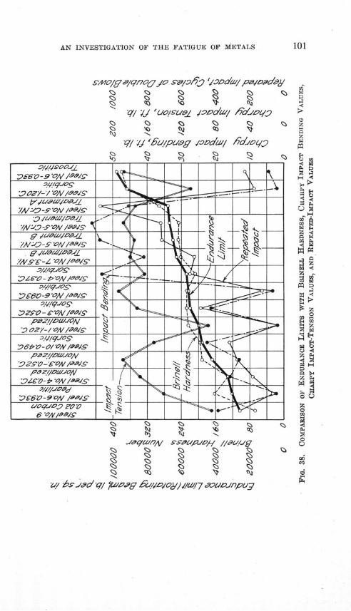
AN INVESTIGATION OF THE FATIGUE OF METALS
szaWo/f a/qno& o Se/yi 'oDd/a pejadoay
"q/ " 'u/puag ~iDndall FdJlo- m
-q fth',7 sW e Js/ 7 ///sL/Jg 0
G o o o oZ
1 1 1 1 1o o0 o0 o oi/ . _ . 9.- - /- . . . . .. _ . . .
Egr)
1-4A< .
z
0 0
E4IIi
0
Zý/ hs--ý.,oV/ F F Ev-///wag
g
rate
g
ILLINOIS ENGINEERING EXPERIMENT STATION
By this procedure the endurance limit of a steel could be determinedin a comparatively short time.
It seems significant that the elastic properties of a materialshould be so unreliable as criteria of fatigue strength, while theBrinell hardness is fairly satisfactory. The point to be emphasizedis that the Brinell hardness test is an empirical test which stressesthe material beyond its proportional elastic limit and gives it apermanent deformation. Perhaps the endurance limit in bendingbears some relation to the properties which a material has when itselastic limit has been exceeded and the metal is in a plastic con-dition. The writers offer no explanation other than that of an em-pirical relation. Without further investigation the Brinell testshould not be regarded as reliable for determining the endurancelimit for non-ferrous metals, nor for determining the endurance limitfor steel with "snowflakes" or other mechanical defects.
The "rise of temperature" test (Chapter V) is a short-timetest for endurance limit which gave more accurate results than did
-the Brinell test, and which, moreover, seems to have a more logicalbasis.
Both the Brinell test and the "rise of temperature" test maybe used as non-destructive tests on parts of machines and structures.
18. Accelerated Methods of Determining Endurance Limit.-The basic tests used in this investigation for determining the endur-ance limit are believed to involve the accurate measurement ofnumber of reversals of definitely known stresses. These tests are,however, time consuming. While the endurance limit of steel maybe determined by.tests running no higher than 10 000 000 repetitions,several days must be consumed in making such a determination.Various accelerated tests have been proposed for determining theendurance limit. Among these may be mentioned impact tests, re-peated-impact tests, short-time tests under repetitions of high stress,magnetic tests, and tests in which the rise of temperature caused byrepeated stress is measured.
Impact tests under a single blow are frequently made, usuallyon flexure specimens which have been notched so that complete rup-ture will occur (Charpy, Izod, or other "notched-bar" tests). Theaction of a single impact is widely different from that of repeated
AN INVESTIGATION OF THE FATIGUE OF METALS
stress; both impact tests and repeated stress tests do, however, em-
phasize the influence of local defects. No correlation could be
observed between the results of reversed-stress tests in this investiga-
tion and the results of single-blow impact tests.
Repeated-impact tests are sometimes made upon flexure speci-
mens notched to localize failure, using a few hundred light blows
in place of one heavy blow. In this class are tests on a "Stanton"
machine or one similar in principle. These tests would seem to be
a somewhat arbitrary compromise between a single-blow impact test
and a repeated-stress test, and it is not possible to measure the stress
set up in the notched bars used. The repeated-impact tests made
in this investigation used a rather heavy blow for the size of speci-
men. The results of these repeated-impact tests failed to show any
correlation with the results of the reversed-stress tests.
Short-time repeated-stress tests under high stresses have fre-
quently been made and have given values for comparison, either
on the basis of a constant stress and relative endurance of two steels,
or on the basis of relative magnitude of stress corresponding to a
given endurance. The results of the present investigation, and of
some other investigations, seem to indicate that short-time, high-
stress tests do not always give results corresponding to long-time,
low-stress tests. This is illustrated by a comparison of the S-N dia-
grams for cold-drawn steel (Fig. 27) with the S-N diagram for 1.20
carbon steel normalized (Fig. 24). Comparing the values of N for
a value of S of 60 000 pounds per square inch, the cold-drawn steel
would seem the more resistant to repeated stress; comparing the
values of N for a value of S of 45 000 pounds per square inch, the
cold-drawn steel fails after about 1 000 000 cycles of stress whilethe 1.20 carbon normalized withstands 100 000 000 cycles withoutfailure. Further discussion of such tests is given in Appendix A.
Magnetic tests to detect microscopic incipient fractures de-veloped under repeated stress hold some promise of success, but areapplicable only to ferrous metals. This test has not been thoroughlydeveloped so far as the writers are aware, but promising preliminaryresults have been obtained by Dr. C. W. Burrows of New York, andby Mr. R. L. Sanford of the United States Bureau of Standards.
A study of the rise of temperature produced after a few hun-dred repetitions of stress has been proposed by various investigators,
ILLINOIS ENGINEERING EXPERIMENT STATION
and especially by Mr. C. E. Stromeyer of Manchester, England, whomade a preliminary experimental investigation of this test. This
test has been given special study in the present investigation and
the results of that study are given in detail in Chapter V by Messrs.Putnam and Harsch.
19. Effect of Cold Work on Fatigue Strength.-The upperhalf of Fig. 27 shows the S-N curves for Steel No. 51, which wasreceived in the form of hot-rolled, half-inch, reinforcing bars. Partof this material was tested as received, part was stretched in tensionuntil the diameter had been reduced to 0.48 inch, part had the di-ameter reduced in the same way to 0.44, and part was bent coldthrough 45 degrees and straightened. The cold stretching was suchthat the material reduced to 0.48 inch was stressed to a point betweenthe yield point and ultimate. The material reduced to 0.44 inchwas stressed up to the ultimate and was about to neck down. Ineach case after the material had been cold worked it was raised to atemperature of 500 degrees F. and held there for 15 minutes, sothat it might recover its elasticity rapidly. The tension test results,which were determined from specimens 1/4 inch in diameter takenfrom the ends of the rotating-beam specimen, are shown in Table 3.The specimens for the rotating-beam machine were prepared in thestandard manner.
Fig. 27 shows that the cold bending raised the endurance limitslightly, about 7 per cent.. The cold stretching raised the endurancelimit in the first case about 25 per cent, and in the second case about46 per cent. The cold stretching in the above two cases raised theproportional elastic limit about 57 and 82 per cent, respectively;and the ultimate about 10 and 19 per cent, respectively. The en-durance limit is therefore influenced to a much smaller degree bycold stretching than is the proportional elastic limit.
The lower half of Fig. 27 shows the S-N curves for Steel No.50, received in the form of 7/16 round bars. Some of this materialwas tested as received, some after annealing at 1300 degrees F.,and some after annealing at 1550 degrees F. Taking the materialannealed at 1550 degrees F. as a standard, the endurance limit forthe 1300 degrees F. annealing is 16 per cent higher, although thisvalue is somewhat in doubt, and that of the material as received is64 per cent higher.
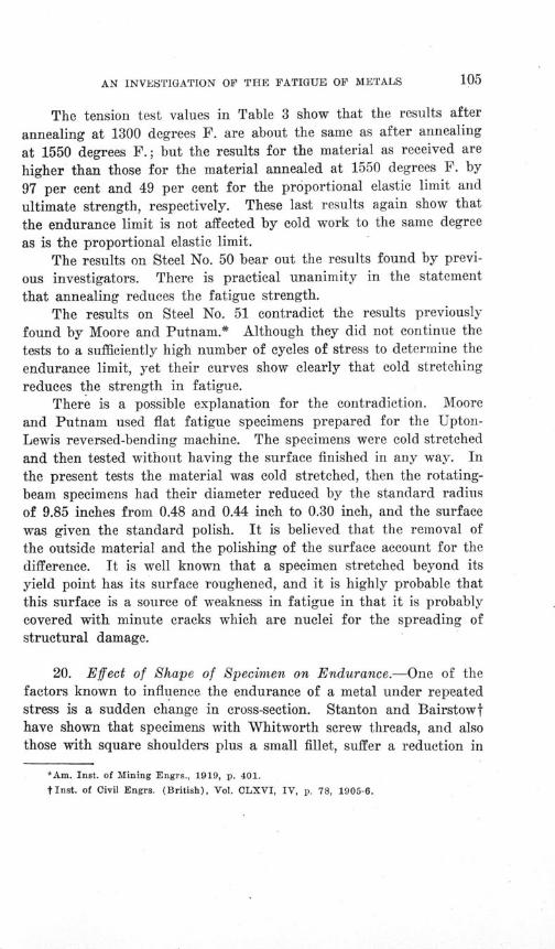
AN INVESTIGATION OF THE FATIGUE OF METALS
The tension test values in Table 3 show that the results after
annealing at 1300 degrees F. are about the same as after annealing
at 1550 degrees F.; but the results for the material as received are
higher than those for the material annealed at 1550 degrees F. by
97 per cent and 49 per cent for the proportional elastic limit and
ultimate strength, respectively. These last results again show that
the endurance limit is not affected by cold work to the same degree
as is the proportional elastic limit.The results on Steel No. 50 bear out the results found by previ-
ous investigators. There is practical unanimity in the statement
that annealing reduces the fatigue strength.The results on Steel No. 51 contradict the results previously
found by Moore and Putnam.* Although they did not continue thetests to a sufficiently high number of cycles of stress to determine theendurance limit, yet their curves show clearly that cold stretchingreduces the strength in fatigue.
There is a possible explanation for the contradiction. Mooreand Putnam used flat fatigue specimens prepared for the Upton-Lewis reversed-bending machine. The specimens were cold stretchedand then tested without having the surface finished in any way. Inthe present tests the material was cold stretched, then the rotating-beam specimens had their diameter reduced by the standard radiusof 9.85 inches from 0.48 and 0.44 inch to 0.30 inch, and the surfacewas given the standard polish. It is believed that the removal ofthe outside material and the polishing of the surface account for thedifference. It is well known that a specimen stretched beyond itsyield point has its surface roughened, and it is highly probable thatthis surface is a source of weakness in fatigue in that it is probablycovered with minute cracks which are nuclei for the spreading ofstructural damage.
20. Effect of Shape of Specimen on Endurance.-One of thefactors known to influence the endurance of a metal under repeatedstress is a sudden change in cross-section. Stanton and Bairstowthave shown that specimens with Whitworth screw threads, and alsothose with square shoulders plus a small fillet, suffer a reduction in
*Am. Inst. of Mining Engrs., 1919, p. 401.
tInst. of Civil Engrs. (British), Vol. CLXVI, IV, p. 78, 1905-6.
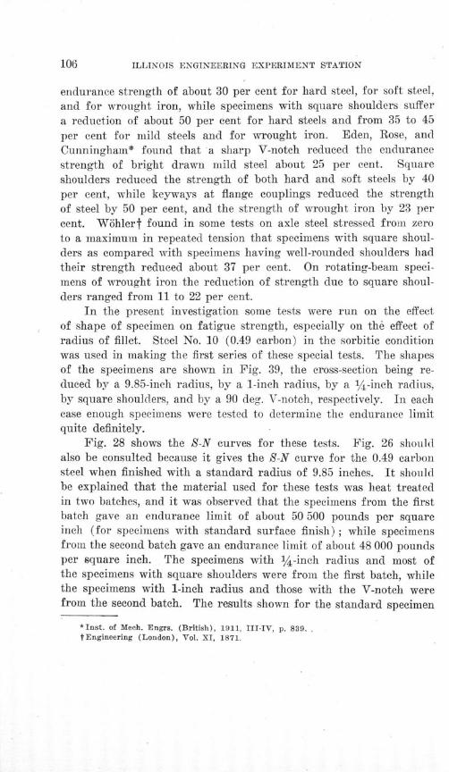
ILLINOIS ENGINEERING EXPERIMENT STATION
endurance strength of about 30 per cent for hard steel, for soft steel,
and for wrought iron, while specimens with square shoulders suffer
a reduction of about 50 per cent for hard steels and from 35 to 45
per cent for mild steels and for wrought iron. Eden, Rose, and
Cunningham* found that a sharp V-notch reduced the endurance
strength of bright drawn mild steel about 25 per cent. Square
shoulders reduced the strength of both hard and soft steels by 40
per cent, while keyways at flange couplings reduced the strength
of steel by 50 per cent, and the strength of wrought iron by 23 per
cent. Wihlert found in some tests on axle steel stressed from zero
to a maximum in repeated tension that specimens with square shoul-
ders as compared with specimens having well-rounded shoulders hadtheir strength reduced about 37 per cent. On rotating-beam speci-mens of wrought iron the reduction of strength due to square shoul-
ders ranged from 11 to 22 per cent.In the present investigation some tests were run on the effect
of shape of specimen on fatigue strength, especially on the effect ofradius of fillet. Steel No. 10 (0.49 carbon) in the sorbitic conditionwas used in making the first series of these special tests. The shapesof the specimens are shown in Fig. 39, the cross-section being re-duced by a 9.85-inch radius, by a 1-inch radius, by a 1/4 -inch radius,by square shoulders, and by a 90 deg. V-notch, respectively. In eachcase enough specimens were tested to determine the endurance limitquite definitely.
Fig. 28 shows the S-N curves for these tests. Fig. 26 shouldalso be consulted because it gives the S-N curve for the 0.49 carbonsteel when finished with a standard radius of 9.85 inches. It shouldbe explained that the material used for these tests was heat treatedin two batches, and it was observed that the specimens from the firstbatch gave an endurance limit of about 50 500 pounds per squareinch (for specimens with standard surface finish); while specimensfrom the second batch gave an endurance limit of about 48 000 poundsper square inch. The specimens with iA-inch radius and most ofthe specimens with square shoulders were from the first batch, whilethe specimens with 1-inch radius and those with the V-notch werefrom the second batch. The results shown for the standard specimen
*Inst. of Mech. Engrs. (British), 1911, III-IV, p. 839..tEngineering (London), Vol. XI, 1871.
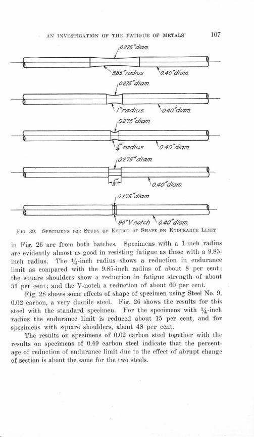
AN INVESTIGATION OF THE FATIGUE OF METALS
985"r7d/us 0 40"di'A7.
0.275"diam.
Ssraed/us 0. 40 d/anz
0275*Niad
h r adus 'o 0. 40 d'am r0 2 75"d/'m.
1 90° V no/ch a 040"d/,m.FiG. 39. SPECIMENS Fro STUDY OF EFFECT OF SHAPE ON ENDURANCE LIMIT
in Fig. 26 are from both batches. Specimens with a 1-inch radius
are evidently almost as good in resisting fatigue as those with a 9.85-
inch radius. The 1/4-inch radius shows a reduction in endurance
limit as compared with the 9.85-inch radius of about 8 per cent;
the square shoulders show a reduction in fatigue strength of about
51 per cent; and the V-notch a reduction of about 60 per cent.
Fig. 28 shows some effects of shape of specimen using Steel No. 9,
0.02 carbon, a very ductile steel. Fig. 26 shows the results for this
steel with the standard specimen. For the specimens with 1/4 -inch
radius the endurance limit is reduced about 15 per cent, and for
specimens with square shoulders, about 48 per cent.
The results on specimens of 0.02 carbon steel together with the
results on specimens of 0.49 carbon steel indicate that the percent-
age of reduction of endurance limit due to the effect of abrupt change
of section is about the same for the two steels.
ILLINOIS ENGINEERING EXPERIMENT STATION
These results indicate the importance of avoiding abrupt changesof section in members of machines which are to be subjected to re-peated stresses. Whenever a change of section is necessary generousfillets should be provided at all shoulders.
A further factor in the effect of form of specimen which mightwell be the subject of investigation is the effect of a fillet with agiven radius with various ratios of maximum diameter of shaft toreduced diameter.
21. Effect of Surface Finish.-The condition of the surface ofa specimen has been shown to have a considerable influence on itsfatigue strength. Eden, Rose, and Cunningham* found that polishedspecimens of mild steel which had their surfaces scratched with anordinary sewing needle suffered an appreciable reduction in fatiguestrength. Specimens of Bessemer steel with a turned surface showeda fatigue strength about 18 per cent lower than specimens of thesame material which had been turned and polished. Sonderickertfound that a rotating-beam specimen of soft steel with a groove 0.003inch deep, cut with a diamond point, had its fatigue strength re-duced by 40 per cent. In some tests in which annealed cold-rolledsteel was stressed in reverse bending beyond the yield point, Kom-merst found that specimens which had been turned in a lathe andspecimens which had been turned and then filed had their endurancereduced 30 and 18 per cent respectively, as compared with specimenswhich had been turned, filed, and polished. In the last named testsendurance was measured by the number of cycles of stress beforerupture.
In order to study the effect of surface finish on the endurancestrength of steel, five different series of specimens were prepared.Steel No. 10, 0.49 carbon sorbitic, was used for the first series.
The five degrees of finish were: first, the standard finish, madewith No. 0 and No. 00 emery cloth; second, a high polish in which,after using No. 0 and No. 00 emery cloth, the specimens were polishedwith emery papers Nos. 1, 0, and 000, and finally with rouge andbroadcloth, a microscope with a magnification of 100 diameters being
* Inst. of Mech. Engrs. (British), 1911, III-IV, p. 839.
tTech. Quart. (Boston), March, 1899.
$ Proc. Int. Assn. for Test. Materials, 1912, Art. V4a.
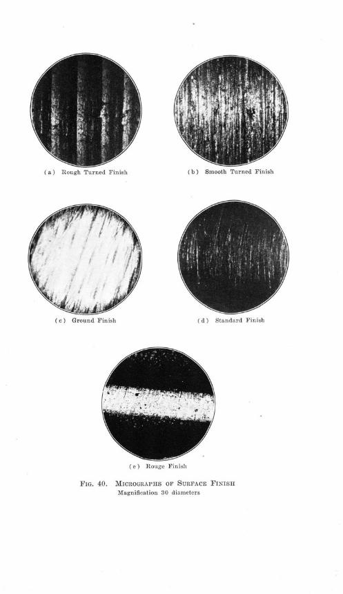
(b) Smooth Turned Finish
(c) Ground Finish (d) Standard Finish
( e ) icouge T'In'sil
FIG. 40. MICROGRAPHS OF SURFACE FINISH
Magnification 30 diameters
% a uugu ±.u )eu - u ii.
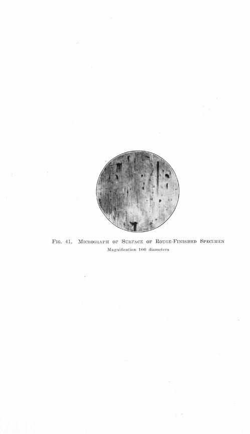
FIG. 41. MICROGRAPH OP SURFACE OF ROUGE-FINISHED SPECIMEN
Magnification 100 diameters

AN INVESTIGATION OF THE FATIGUE OF METALS
used to make sure that all scratches were removed; third, a ground
finish obtained with a grinding wheel; fourth, a smooth-turned finish
with a lathe tool; and fifth, a rough-turned finish with a lathe tool.
Fig. 40 shows the photographs, under a magnification of 30 diame-
ters, of the five degrees of finish. Fig. 41 shows the rouge finish
under a magnification of 100 diameters, and indicates the degree to
which the very fine scratches were removed.
Fig. 29 shows the S-N diagrams obtained with four of these
series. Fig. 26 should be consulted also, since it shows the results
obtained with the standard finish. As was the case with the tests
discussed in Section 20, the material for the first series was taken
from two batches of steel, heat treated at two different times. The
first batch showed an endurance limit of about 50 500 pounds per
square inch and the second batch an endurance limit of about 48 000
pounds per square inch. The rouge-finish specimens were taken from
the first batch, the rough-turned were taken from the second batch,
while the ground and the smooth-turned were taken from both
batches, as were the specimens with standard finish.
The S-N curves make it clear that the rouge finish is probably
slightly better than the standard finish in withstanding fatigue. The
ground-finish endurance limit is slightly lower than the standard-
finish, and the smooth-turned and rough-turned fall below the ground-
finish in the order named. The rough-turned finish, the weakest,
has an endurance limit about 18 per cent lower than the rouge finish.
There is so little difference between the rouge finish and the
standard finish, especially in view of the fact that a number of the
standard-finish specimens of the first batch ran out to 10 000000
cycles of stress without failure at a unit stress of slightly over 50 000
pounds per square inch, that it is felt that the use of the standard
finish is fully justified. The rouge finish was of course very expen-
sive and time consuming, and is difficult to maintain free from cor-
rosion; therefore it is not considered practical.
Fig. 29 shows some results of the effect of surface finish on speci-
mens of Steel No. 9, 0.02 carbon, a very soft steel. The endurance
limit for the rough-turned specimens seems to be slightly less than
for the smooth-turned. The reduction in endurance limit of the
turned specimens as compared with specimens with standard finish
(see Fig. 26) ranges from 8 to 12 per cent.

ILLINOIS ENGINEERING EXPERIMENT STATION
Comparing the results of tests on specimens of 0.02 carbon steel
with specimens of 0.49 carbon steel, sorbitic, it is seen that the per-
centage reduction in endurance limit due to smooth turning and to
rough turning, as compared with the standard finish, is about the
same for the two steels.
The results of this study make it clear that the finish of a ma-
chine member subjected to fatigue may have an appreciable effect
on its endurance strength. It also appears that fine grinding would
probably be satisfactory as a commercial finish.
22. Effect of Overstress.-From the standpoint of Bausechinger's
theory regarding failure due to fatigue, and also from the fact that
in practice many machine members subjected to fatigue are occa-
sionally overstressed, it seemed desirable to determine whether stress-
ing a material above its endurance limit for a certain number of
cycles and subsequently testing it in fatigue in the usual manner
would result in any change in the endurance limit.
The material used in this study for the first series of tests was
Steel No. 10, 0.49 carbon, sorbitic.
Six different combinations of overstress and number of cycles
were used. The endurance limit of the material having been de-
termined in the standard manner (See Fig. 26), about 12 specimens
were subjected to 5000 cycles of stress, the unit stress used being
10 per cent higher than the endurance limit previously determined.
After this treatment the specimens were tested in the usual manner
with varying stresses to determine whether the endurance limit
would now be different. In the same manner other series of speci-
mens were tested with 20, 29, 29, 35, and 38 per cent of overstress,
the number of cycles of applied overstress being 5000, 5000, 1000,1000, and 100 respectively.
The material for these tests, just as was the case in the previous
section, was taken from two batches of steel heat treated at two dif-
ferent times. The first batch showed an endurance limit of about
50 000 pounds per square inch and the second batch one of about48 000 pounds per square inch. The specimens subjected to 10, 20,and 38' per cent overstress were taken from the first batch of steel,and the calculation in per cent of their endurance limits is basedupon an endurance limit of 50 500 pounds per square inch. Those
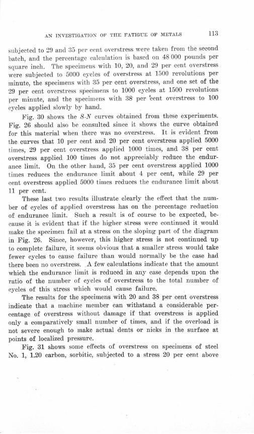
AN INVESTIGATION OF THE FATIGUE OF METALS
subjected to 29 and 35 per cent overstress were taken from the second
batch, and the percentage calculation is based on 48 000 pounds per
square inch. The specimens with 10, 20, and 29 per cent overstress
were subjected to 5000 cycles of overstress at 1500 revolutions per
minute, the specimens with 35 per cent overstress, and one set of the
29 per cent overstress specimens to 1000 cycles at 1500 revolutions
per minute, and the specimens with 38' per 'cent overstress to 100
cycles applied slowly by hand.
Fig. 30 shows the S-N curves obtained from these experiments.
Fig. 26 should also be consulted since it shows the curve obtained
for this material when there was no overstress. It is evident from
the curves that 10 per cent and 20 per cent overstress applied 5000
times, 29 per cent overstress applied 1000 times, and 38 per cent
overstress applied 100 times do not appreciably reduce the endur-
ance limit. On the other hand, 35 per cent overstress applied 1000
times reduces the endurance limit about 4 per cent, while 29 per
cent overstress applied 5000 times reduces the endurance limit about
11 per cent.These last two results illustrate clearly the effect that the num-
ber of cycles of applied overstress has on the percentage reductionof endurance limit. Such a result is of course to be expected, be-
cause it is evident that if the higher stress were continued it wouldmake the specimen fail at a stress on the sloping part of the diagramin Fig. 26. Since, however, this higher stress is not continued up
to complete failure, it seems obvious that a smaller stress would takefewer cycles to cause failure than would normally be the case had
there been no overstress. A few calculations indicate that the amountwhich the endurance limit is reduced in any case depends upon theratio of the number of cycles of overstress to the total number ofcycles of this stress which would cause failure.
The results for the specimens with 20 and 38 per cent overstress
indicate that a machine member can withstand a considerable per-centage of overstress without damage if that overstress is applied
only a comparatively small number of times, and if the overload is
not severe enough to make actual dents or nicks in the surface atpoints of localized pressure.
Fig. 31 shows some effects of overstress on specimens of steelNo. 1, 1.20 carbon, sorbitic, subjected to a stress 20 per cent above

ILLINOIS ENGINEERING EXPERIMENT STATION
the normal endurance limit; in one case 5000 cycles of overstresswere applied, and in the other case 10 000 cycles. The endurancelimit seems to be slightly lower for the specimens subjected to 10 000cycles of overstress than for the specimens subjected to 5000 cycles,and the reduction of endurance limit of the overstressed specimensas compared with material not subjected to overstress ranges from12 to 14 per cent. Fig. 24, which gives the results for this materialnot subjected to overstress, should be consulted for comparison.
Comparing the results for 5000 cycles with 20 per cent over-stress for the 0.49 carbon steel, sorbitic, and the 1.20 carbon steel,sorbitic, it is evident that the effect of overstress in reducing theendurance limit is more serious for the 1.20 carbon steel than for the0.49 carbon steel.
The three studies of shape, surface finish, and overstress give agood idea of the relative seriousness of their effects in reducing theendurance limit. The maximum reduction noted in the overstressexperiments was 14 per cent, that in the surface finish experimentswas 18 per cent, while that in the experiments on shape was 60 percent. While both overstress applied for a short time and poor sur-face finish reduce the endurance limit, the most serious reductionresults from sudden changes in cross-section, especially in the caseof machine members having square shoulders and sharp notches any-where in their length.
Overloading a machine part may be accompanied by the forma-tion of grooves and deep scratches due to wear, and these groovesand scratches may have a greater influence in reducing strength underrepeated stress than the direct effect of the nominal overstress accom-panying the overload.
23. Theories of Nature of Fatigue of Metals.-One theory ofthe nature of the fatigue of metals is the "crystallization" theorywhich had its origin in a study of the fractured surfaces of machineparts that had failed under repeated stress. These surfaces, evenfor soft material like wrought iron, appeared jagged and crystalline.This theory implied that under the action of repeated stress the in-ternal structure of a metal changed from fibrous to crystalline, andthat different metals varied in their resistance to this change.
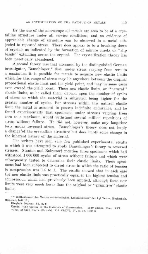
AN INVESTIGATION OF THE FATIGUE OF METALS
By the use of the microscope all metals are seen to be of a crys-talline structure under all service conditions, and no evidence ofappreciable change of structure can be observed in a metal sub-jected to repeated stress. There does appear to be a breaking downof crystals as indicated by the formation of minute cracks or "slipbands" extending across the crystal. The crystallization theory hasbeen practically abandoned.
A second theory was that advanced by the distinguished Germaninvestigator, Bauschinger,* that, under stress varying from zero toa maximum, it is possible for metals to acquire new elastic limitswhich for this range of stress may lie anywhere between the originalproportional elastic limit and the yield point, and may in some caseseven exceed the yield point. These new .elastic limits, or "natural"elastic limits, as he called them, depend upon the number of cyclesof stress to which the material is subjected, being higher for thegreater number of cycles. For stresses within this natural elasticlimit the metal is assumed to possess indefinite endurance, and hefound experimentally that specimens under stresses varying fromzero to a maxiinum would withstand several million repetitions ofstress without failure. He did not, however, make any long-timetests under reversed stress. Bauschinger's theory does not implya change 'of the crystalline structure but does imply some change inthe inherent nature of the material.
The writers have seen very few published experimental resultsin which it was attempted to apply Bausehinger's theory to reversedstresses. Stanton and Bairstowt mention three specimens which hadwithstood 1 000 000 cycles of stress without failure and which weresubsequently tested to determine their elastic limits. These speci-mens had been subjected to direct stress in which the ratio of tensionto compression was 1.4 to 1. The results showed that in each casethe new elastic limit was practically equal to the highest tension andcompression which had previously been applied, although these newlimits were very much lower than the original or "primitive" elasticlimits.
* " Mittheilungen des Mechanisch-technischen Laboratoriums" der kgl. Techn. Hochachule,Muiinehen, heft 13;
Dingler's Journal, Bd. 224;Unwin, "The Testing of the Materials of Construction." 1910 edition, Chap. XVI.tinst. of Civil Engrs. (British), Vol. CLXVI. IV, p. 78. 1905-6
ILLINOIS ENGINEERING EXPERIMENT STATION
Popplewell* determined the natural elastic limits by only 10
cycles of reversed direct stress and then attempted to check these
values by rotating-beam tests. His natural elastic limits were lower
than the primitive elastic limits, and the endurance limits from the
rotating-beam tests were about equal to the primitive elastic limits.
It seems to the writers that the check tests should have been madewith a direct-stress machine instead of a rotating-beam, and it alsoseems questionable whether 10 cycles of stress would be enough todevelop Bauschinger's natural elastic limits.
A series of tests to throw light on this matter is discussed inSection 36, "Effect of Repeated Understressing."
A third theory has been suggested by various investigators, andwas developed by the writers, who afterwards found that it had beenpreviously elaborated by Gilchrist.t This theory, while not directlycontradictory to that of Bauschinger, presents a different picture ofthe mechanism of fatigue failure.
In discussing Wohler's results Gilchrist has stated this theoryas follows:
"(1) The average stress in the bars broken in WShler's machines didnot reach the statical breaking load.
" (2) The fracture was caused by the statical breaking limit being ex-ceeded at one point only, from which, when once started, rupturp spread, atfirst rapidly, then more slowly, sometimes continuing to complete separation ofthe two parts of the bar, but occasionally stopping short of complete rupture.
" (3) The raising of the stress at the point where fracture commencedwas due to an irregularity in the bar. This might be an irregularity or dis-continuity in the metal, either on the surface or in the body of the bar.t
" (4) A bar of uniform strength whose surface was perfectly smooth,with no sharp corners in the longitudinal configuration and the structure ofwhich was perfectly homogeneous would endure, without breaking, an indefinitenumber of repetitions of a stress varying between zero and a value near to thebreaking strength.
*Inst. of Civil Engrs. (British), Vol. CXCVII, III, p. 264, 1913-14.
t The Engineer (London), Vol. 90, p. 203.
t The frequent occurrence of high localized stress which is usually overlooked in usingthe ordinary methods of computation is strikingly demonstrated by the mathematical workof Inglis and others, and by the experimental work of Coker and Preuss. See:
Trans. Inst. of Naval Architects (British), Vol. LV, Part I, p. 219, 1913;Engineering, London, April 21, 1911, and March 8, 1912;Zeit. des Ver. Deut. Ing., 1913, Part 1, p. 664;"Johnson's Materials of Construction." Fifth Edition, p. 663.
AN INVESTIGATION OF THE FATIGUE OF METALS
S(5) A bar similar to that under (4) could, under certain conditions,
endure an indefinite number of repetitions of a load varying between tension
and compression of equal values both beyond the ordinary primitive elastic
limits."
The writers agree in general with the foregoing statements, but,
on account of the fact that a perfectly homogeneous material is not
likely to be found for engineering purposes, they believe that the
limitations of statement (4) as applied to ordinary metals should
be set forth for the sake of clearness. It appears to them that the
practical limit even for the case of stress varying from zero to a
maximum will be the yield point of the material.
This theory may be called the theory of non-homogeneity or
of localized stress. The effect of external non-homogeneity due to
scratches, tool marks, square shoulders, and notches is well known
and is discussed in another section of this bulletin. Internal non-
homogeneity may be due to blow-holes, pipes, inclusion of slag, ir-
regularity of crystalline structure on account of the presence of two
or more constituents of varying strength, variation in orientation
of crystals, or the presence of initial stresses caused by mechanical
working or heat treatment. Owing to the minute area over which it
exists, this localized stress produces no appreciable effect under a
single load, but under load repeated many times there is started
from this area a microscopic crack, at the root of which there exists
high localized stress which under repetition of stress spreads until
it finally causes failure.The writers do not look upon these fatigue failures as being due
necessarily to accidental flaws or irregularities. Such failures may,
in practice, often be due to such causes, but the definiteness of the
endurance limits found in the present tests points to the conclusion
that the endurance limit is a property of the material just as much as
the ultimate strength. If in these tests the failure is due to flaws,
then it is believed that these flaws are an inherent part of the struc-
ture of the particular steel which is being tested.
As evidence supporting this theory the following facts are given:
(1) In the case of material of homogeneous structure, such
as a specimen of 0.02 carbon steel, which is almost pure ferrite, or
a specimen of 0.93 carbon steel, which is almost pure pearlite, it is
found possible to develop an endurance strength nearly or quite

ILLINOIS ENGINEERING EXPERIMENT STATION
equal to the primitive elastic limit. This is a direct verification of(5) in Gilchrist's theory.
(2) In the case of steels composed of a mixture of ferrite andpearlite the endurance limit is found below the primitive elasticlimit, indicating to the writers' minds a progressive failure, first ofthe weaker constituent, then of the stronger.*
(3) Mathematical analysis, special measurement of stress dis-tribution, and repeated-stress tests of specimens with notches andspecimens with rough surface finish all indicate how important me-chanical imperfections in surface may be in increasing localizedstress and hence in reducing fatigue strength. There would seemto be no reason for doubting that internal non-homogeneity producesa similar effect.
The actual mechanism of fatigue failure has not been studiedfor a great variety of steel structures. It is known that in the softersteels the failure seems to be due to the production of slip bands(see Appendix B) which finally develop into cracks. For a veryhomogeneous material like 0.02 carbon steel it seems probable thata certain unit stress will be sufficient to cause slipping in the glidingplanes of the crystals. Thereafter, the adjacent material will beginto slip under succeeding repetitions of stress until all the othermaterial has yielded the same amount. This action will continueuntil the first material has reached the ultimate strength and actuallyopened up a crack. From then on the action will be rapid and failurewill occur soon.
Just what happens in a material like the chrome-nickel, treat-ment A, in which the endurance limit is very much below the pro-portional elastic limit is not altogether clear. It is likely that non-homogeneity and especially the presence of internal stresses play animportant part.
*It should be borne in mind that localized weakness may be caused by strains due toheat treatment as well as by non-uniformity of metallographic structure. Tests reportedverbally by D. J. McAdam, of the U. S. Naval Academy Eng. Exp. Sta., indicate thatthorough annealing as well as homogeneity of structure seems to be effective in giving ahigh ratio of endurance limit to proportional elastic limit. This is further confirmed bytest results on annealed steel of various carbon contents as shown by Fig. 44 and Table 10.

AN INVESTIGATION OF THE FATIGUE OF METALS
V. "RISE OF TEMPERATURE" METHOD OF DETERMINING
ENDURANCE LIMIT
By W. J. PUTNAM and J. W. HARSCH*
24. Thermal Phenomena in Metals Under Stress.-The de-
termination of endurance limit by the actual application of repeated
stress, by a test on a rotating-beam testing machine, for example.
requires so much time that it is not a practical commercial test andvarious other methods have been tried, such as the examination ofthe hysteresis loop, magnetic exploration, and calorimetric determi-nation.
The fact was first mentioned by Lord Kelvinf in 1.855 that amaterial subjected to stress within its ordinary static elastic limitis subject to a change of temperature, cooling if in tension, and heat-ing if in compression. Since that time Turner,t. Rasch¶, and Cappand Lawson§ have made use of this thermal change as a method ofdetermining the elastic limit in tension, defining it as the least stressat which the temperature of the specimen begins to rise.
In 1913 C. E. Stromeyer** tried the method of determining thefatigue limit under alternating stress conditions by means of the heatgenerated due to inelastic action. He located the endurance limitat that minimum alternating stress which after a few hundred rapidrepetitions will just generate heat in the test pieces. His determina-tions of heat were made by sensitive mercury thermometers immersedin a steady stream of water just before and just after it had flowed
*Professor W. J. Putnam of the Department of Theoretical and Applied Mechanics ofthe University of Illinois, and J. W. Harsch, Metallurgist with the Investigation of theFatigue of Metals. Professor Putnam was responsible for the preliminary development ofthe apparatus and methods of testing, and Mr. Harsch developed the present form of ap-paratus used, and carried out the "rise of temperature" tests made in connection with thisinvestigation.
t Quart. Math. Journal, 1855.
tTrans. Am. Soc. of Civil Engrs., Jan.. 1902.
¶ Proc. Int. Assn. for Test. Materials, Art. VII, 1909.
§Proc. Int. Assn. for Test. Materials, Art. IX8, 1912.
**Memorandum of the Chief Engineer of the Manchester (England) Steam Users Association. 1913. See also Engineering, London. June 19. 1914.
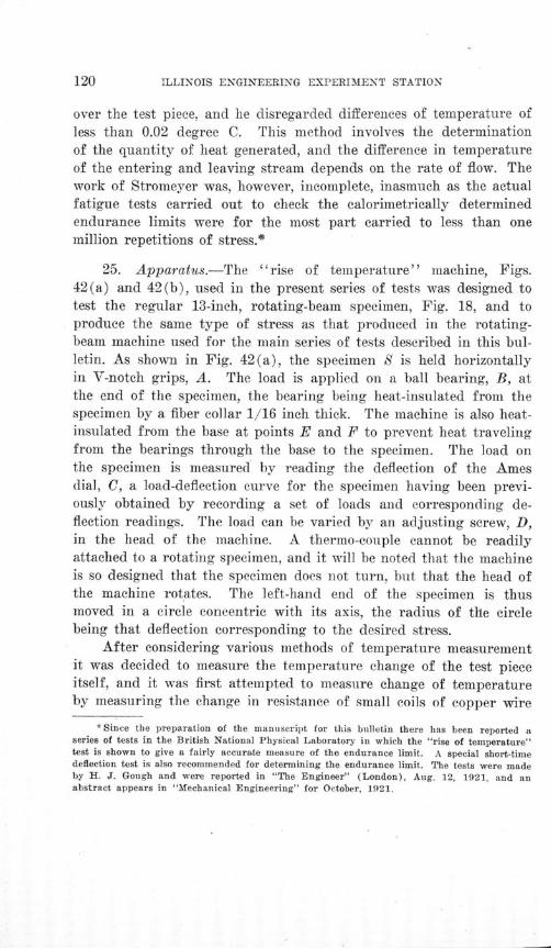
ILLINOIS ENGINEERING EXPERIMENT STATION
over the test piece, and he disregarded differences of temperature ofless than 0.02 degree C. This method involves the determination
of the quantity of heat generated, and the difference in temperatureof the entering and leaving stream depends on the rate of flow. Thework of Stromeyer was, however, incomplete, inasmuch as the actualfatigue tests carried out to check the calorimetrically determinedendurance limits were for the most part carried to less than onemillion repetitions of stress.*
25. Apparatus.-The "rise of temperature" machine, Figs.42(a) and 42(b), used in the present series of tests was designed totest the regular 13-inch, rotating-beam specimen, Fig. 18, and toproduce the same type of stress as that produced in the rotating-beam machine used for the main series of tests described in this bul-letin. As shown in Fig. 42(a), the specimen S is held horizontallyin V-notch grips, A. The load is applied on a ball bearing, B, atthe end of the specimen, the bearing being heat-insulated from thespecimen by a fiber collar 1/16 inch thick. The machine is also heat-insulated from the base at points E and F to prevent heat travelingfrom the bearings through the base to the specimen. The load onthe specimen is measured by reading the deflection of the Amesdial, C, a load-deflection curve for the specimen having been previ-ously obtained by recording a set of loads and corresponding de-flection readings. The load can be varied by an adjusting screw, D,in the head of the machine. A thermo-couple cannot be readilyattached to a rotating specimen, and it will be noted that the machineis so designed that the specimen does not turn, but that the head ofthe machine rotates. The left-hand end of the specimen is thusmoved in a circle concentric with its axis, the radius of the circlebeing that deflection corresponding to the desired stress.
After considering various methods of temperature measurementit was decided to measure the temperature change of the test pieceitself, and it was first attempted to measure change of temperatureby measuring the change in resistance of small coils of copper wire
* Since the preparation of the manuscript for this bulletin there has been reported aseries of tests in the British National Physical Laboratory in which the "rise of temperature"test is shown to give a fairly accurate measure of the endurance limit. A special short-timedeflection test is also recommended for determining the endurance limit. The tests were madeby H. J. Gough and were reported in "The Engineer" (London), Aug. 12, 1921, and anabstract appears in "Mechanical Engineering" for October, 1921.

(b)
FIG. 42. MACHINE FOR "'RISE OF TEMPERATURE " TESTS


AN INVESTIGATION OF THE FATIGUE OF METALS
held directly against the specimen. One coil was attached at thesection of greatest stress and the other to the unstressed portion ofthe specimen just beyond the holding clamp, thus neutralizing theeffect of any change in temperature of the machine. The coils hav-ing been balanced on a Wheatstone slide-wire bridge, any change intemperature would unbalance the system by an amount which, asindicated by the galvanometer, would denote the amount of changein temperature. The unbalancing, however, changed the amount ofcurrent flowing through each coil and therefore caused an addedchange in temperature of the coils. Then, too, the coils were so deli-cate that the repeated handling and the slight friction to which theywere subjected soon destroyed the insulation on the wires.
Differential copper-constantan thermo-couples made from No. 30B and S gage wire were then used. These were attached in locationscorresponding to those used for the resistance coils, the one, K, atthe section of greatest stress being tightly taped against the steel,and the other, L, separated from the steel by a single layer of thinpaper. This arrangement proved very satisfactory and calibrationshowed it to be sensitive to 0.003 degree C. The couples were con-nected in series with a Leeds and Northrup, Type H, D'Arsonvalgalvanometer, shown in Fig. 42(b). When the couples were atthe same temperature no deflection was shown, but when eithervaried in temperature from the other a corresponding deflectionoccurred.
26. Materials.-By the rise of temperature method severalsteels in the general series were tested, thus checking the reliabilityof this method since the endurance limit of each steel was definitelyknown from long-time tests, and the series covered a wide range.Duplicate and triplicate tests were made on several of the steels toascertain the reliability with which the endurance limit could bedetermined, and the results thus obtained were well within the limitsof the precisiojn of stress adjustment.
27. Tests.-The test finally adopted as a standard consists inrunning the machine for 30 seconds at a speed of 1000 revolutionsper minute at a known stress and recording the maximum deflec-tion of the galvanometer. Then, with a series of such readings cor-
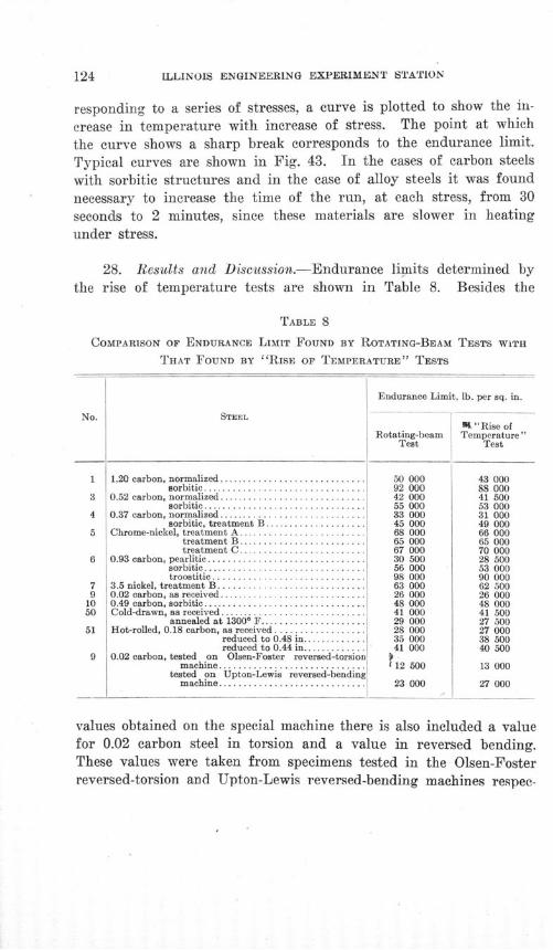
124 LLLINOIS ENGINEERING EXPERIMENT STATION
responding to a series of stresses, a curve is plotted to show the in-
crease in temperature with increase of stress. The point at which
the curve shows a sharp break corresponds to the endurance limit.
Typical curves are shown in Fig. 43. In the cases of carbon steelswith sorbitic structures and in the case of alloy steels it was foundnecessary to increase the time of the run, at each stress, from 30seconds to 2 minutes, since these materials are slower in heatingunder stress.
28. Results and Discussion.-Endurance limits determined bythe rise of temperature tests are shown in Table 8. Besides the
TABLE 8
COMPARISON OF ENDURANCE LIMIT FOUND BY ROTATING-BEAM TESTS WITH
THAT FOUND BY "RISE OF TEMPERATURE" TESTS
Endurance Limit, lb. per sq. in.
No.
1
3
4
5
6
79
1050
51
9
STEEL I
W "Rise ofRotating-beam Temperature"
Test Test
1.20 carbon, normalized .......... . .............. . . . . 50 000 43 000sorbitic ................................ 92 000
0.52 carbon, normalized ....... . . ................. .. 42 000sorbitic ................................ 55 000
0.37 carbon, normalized ............................. 33 000sorbitic, treatment B .................... . 45 000
Chrome-nickel, treatment A ............. ............ . . 68 000treatment B ......................... 65 000treatment C ......................... 67 000
0.93 carbon, pearlitic ............................... 30 500sorbitic. ................................ 56 000troostitic .............................. 98 000
3.5 nickel, treatment B .......... ................... 1 63 0000.02 carbon, as received........... ................. 26 0000.49 carbon, sorbitic.............................. . 48 000Cold-drawn, as received ............................. 41 000
annealed at 1300* F...... . ............. .. 29 000Hot-rolled, 0.18 carbon, as received .................. 28 000
reduced to 0.48 in............. 35 000reduced to 0.44 in............. 41 000
0.02 carbon, tested on Olsen-Foster reversed-torsion )m achine ............................. f 12 500
tested on Upton-Lewis reversed-bendingm achine ............................. 23 000
88 00041 50053 00031 00049 00066 00065 00070 00028 50053 00090 00062 50026 00048 00041 50027 50027 00038 50040 500
13 000
27 000
values obtained on the special machine there is also included a valuefor 0.02 carbon steel in torsion and a value in reversed bending.These values were taken from specimens tested in the Olsen-Fosterreversed-torsion and Upton-Lewis reversed-bending machines respec-
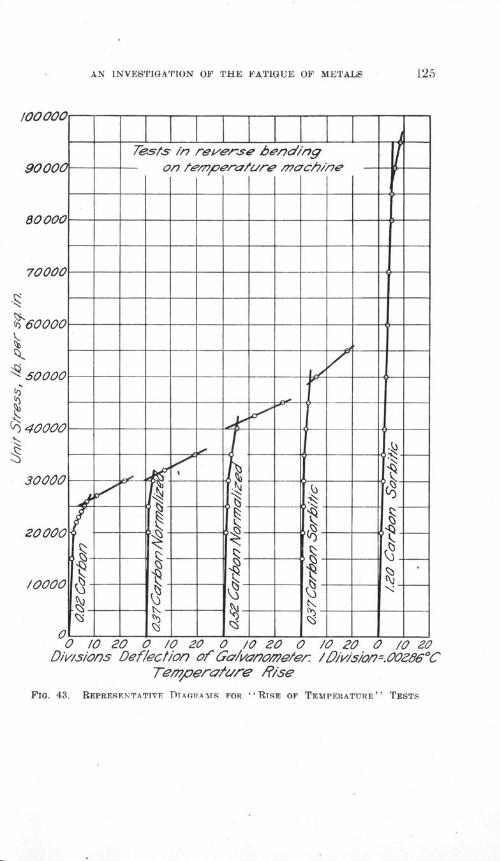
AN INVESTIGATION OF THE FATIGUE OF METALS
Tempera/ure R/se
FIG. 43. REPRESENTATIVE DTAGRAMS FOR "RTSE OF TEMPERATITRE" TESTS
f,

ILLINOIS ENGINEERING EXPERIMENT STATION
tively, with thermo-couples attached to the specimen. Table 8 alsocontains for the purpose of comparison the values of endurancelimits as determined in the rotating-beam machine and in the tem-perature machine. This comparison is shown diagramatically inFig. 37.
There is a reasonably close coincidence between the endurancelimits given by the long-time rotating-beam tests and those given bythe temperature tests.
The method of determining the endurance limit from the curveobtained in a temperature test is shown in Fig. 43. The endurancelimit is taken at the point shown by the intersection of the lines.The curves in this figure are typical. Most of the curves show aslight break considerably below the endurance limit. It is probablethat there is at this point a very slight incipient damage in someweaker constituent, but that the load is still sustained by the strongerconstituent and, as shown by actual tests, no failure results untilthe higher stress is reached. This first break decreases in amountwith an increase of the carbon content in the normalized steels, andis also smaller when the steel has been given such heat treatmentas to produce a sorbitic structure. It would seem that this firstbreak may depend upon some property of the ferrite crystal andso may decrease in sharpness with a decrease in percentage of fer-rite and with a more complete dispersion ,of cementite, such as oc-curs in sorbite. This is well shown by the curves in Fig. 43, sincethese curves represent steels which cover a wide range of carboncontent and also show two different heat treatments.
It may be possible that this first break indicates the absoluteendurance limit, i. e., the stress under which the material will with-stand an infinite number of repetitions. This of course cannot bechecked by actual applications of stress, but it is not impossibleto conceive that, at the endurance limit determined by tests to100 000 000 repetitions, the curve may still have a very slight down-ward trend, which, if the tests were carried to billions of repetitions,might bring the endurance limit to the value shown by the firstbreak of the temperature curve. The characteristic curves also showa very slight but gradual increase in temperature with increase ofstress below the endurance limit.
AN INVESTIGATION OF THE FATIGUE OF METALS 127
It is believed that a machine of this type, especially in conjunc-
tion with two or three rotating-beam machines, is a good piece of
equipment for the average college or commercial laboratory, and
that with such equipment the time and expense of fatigue investi-
gations or commercial routine fatigue tests would be very materially
lessened. With such equipment, using the temperature machine for
a preliminary test, and the rotating-beam machine to obtain check
results, it would be quite possible to determine endurance limits
with a fair degree of accuracy within a few hours.
Problems worthy of further investigation include:
(1) An application of the principle of temperature meas-
urement to a direct tension-compression fatigue machine and
the determination of endurance limits under such stress.
(2) A more complete investigation of the first break in
the curves by the use of more sensitive couples.
(3) A study of non-ferrous materials.
ILLINOIS ENGINEERING EXPERIMENT STATION
VI. SUBJECTS FOR FURTHER INVESTIGATION
29. Effect of Repetition of Stress Not Reversed.-The repeated-
stress tests described in this bulletin have all involved complete
reversal of stress. This is the severest type of repeated stress and
is quite common in practice. It is, however, evident that manymachine parts are subjected to varying stresses in which the varia-tion does not involve a complete reversal. For example, stresses ina railroad rail vary from a maximum in one direction to a stressin the other direction of about one-quarter the magnitude of themaximum stress; chains are subjected to stresses varying from zeroto a maximum. Comparatively little work has been done on thestudy of the effect of range of stress. In general it is estimatedthat a material which will withstand a completely reversed stress,S1, will withstand a stress of one kind only varying from zero to amaximum of S 2 equal to about 1.5 times the magnitude of S8, andthat values between these limits may be obtained by interpolation.
Tests to determine the effect of range of stress are much needed,and in connection with the present investigation a machine has beendesigned and preliminary tests have been made under repeatedstresses not completely reversed.
30. Tests on Other Ferrous Metals.-The tests recorded in thisbulletin constitute a reconnaissance in the field of ferrous metals;they by no means constitute a complete study. Many other kindsof ferrous metals could well be studied, especially alloy steels, ofwhich only two have been studied. Vanadium steels, molybdenumsteels, and possibly tungsten and manganese steels at once suggestthemselves. Methods developed in this investigation, especially the"rise-of-temperature" test, may be expected to shorten greatly thetime required for determining endurance limits.
31. Tests on Non-Ferrqus Metals.-This investigation in itsfirst stages was definitely limited to the ferrous metals. The studyshould be extended to the non-ferrous metals-to brasses, bronzes,copper, aluminum, aluminum alloys, and possibly magnesium alloys.
,AN INVESTIGATION OF THE FATIGUE OF METALS 129
Some tests on these metals have been made at commercial and gov-ernment laboratories, but the data available are insufficient for draw-ing even tentative conclusions. Some experimental evidence tendsto show that a higher number of repetitions of stress is necessaryto develop the endurance limit for non-ferrous metals than for ironand steel.
32. Effect of Heat Treatment.-In the tests recorded in thisbulletin, materials have been tested with various heat treatments.The object of variation was to produce certain characteristic struc-tures in the metals. For many of the metals a much more detailedstudy of the effect of heat treatment on resistance to repeated stressshould be made. It has been found in certain cases that the heattreatment which gives maximum static strength will not give maxi-mum resistance to repeated stress, and many more tests should bemade along this line. It is evident that the careful determinationof the heat treatment which will give maximum resistance to re-peated stress for any steel is a matter of great practical importance.The development of a reliable accelerated test for the endurancelimit, such as the "rise of temperature" test, will greatly expeditesuch a study of heat treatments for ferrous metals.
33. Direct Tension-Compression Tests.-Under a bending stressonly the outside fibers receive the maximum stress while the insidefibers of the specimens have a lower stress. A series of tests in whichsome specimens are subjected to direct tension and compression, whileothers are subjected to reversed bending should throw considerablelight on the importance of the resisting ability of the understressedfibers of flexural members. A machine for producing repeated alter-nations of direct tension and compression has been designed and con-structed and is being calibrated and adjusted.
34. Strength Under Reversed Shearing Stress.-In this bulletintest results are given for a few steels tested under reversed torsionin the Olsen-Foster machine. These specimens have been subjectedto reversed shearing stress, and as pointed out in Section 15, "SomeFactors Influencing the Endurance Limit," a ratio of endurancelimit in shear to that in reversed bending of about 0.52 is indicated.Of late years it has become evident that shearing stress is frequently

ILLINOIS ENGINEERING EXPERIMENT STATION
the cause of failure in material, and a much more complete studyof resistance to repeated shearing stress should be made. A machinefor producing and measuring repeated alternations of shearing stresshas been designed and constructed and is being adjusted and cali-brated.
35. Study of Mechanism of Fatigue Failure.-The work ofEwing, Humphrey, Rosenhain,* and others on the development ofslip lines in metals under stress has done much to explain whymetals fail in fatigue. These experiments were generally made onsoft metals; similar studies should be made on metals in the heat-treated condition, in order to examine the mechanism of fatiguemore in detail. In this connection a study of the actual path offracture in fatigue, with a microscope of high- magnification, wouldbe valuable.
36. Effect of Repeated Understressing.-Incidental to the studyof overstressing in its effect on the endurance limit, discussed inSection 22, a few results were obtained on the effect of subjectinga specimen to a unit stress below the endurance limit and subse-quently testing it at higher stresses. The few results observed in-dicate that such understressing may be beneficial in increasingresistance to fatigue, possibly by readjusting internal stress. Suchtests also have a direct bearing on Bauschinger's theory of fatiguefailure.
A study is contemplated in which a series of specimens will bestressed to, say, 10 per cent less than the endurance limit, for per-haps 10 000 cycles, and after this treatment subjected to variousstresses in the usual manner, to determine whether any change hasoccurred in the endurance limit. By making several series of tests,using various percentages of understress, and with various numbersof cycles from 10 000 to perhaps 1 000 000, it will be possible todetermine the effect of such understressing on the resistance to fa-tigue, and also the influence which the number of cycles of suchunderstressing has on the result.
37. Strength of Cast Metal Under Repeated Stress.-The testsrecorded in this bulletin, and nearly all other tests under repeated
*Rosenhain, "Metallurgy; an Introduction to the Study of Physical Metallurgy."
AN INVESTIGATION OF THE FATIGUE OF METALS
stress, have been made on rolled metal. The extensive use of steelcastings and of castings of non-ferrous metals for stress-resistingparts makes some knowledge of the fatigue strength of such ma-terials of importance. It is well known that the elastic strengthof castings is low as compared with the ultimate strength, but thereare no test results from which to judge whether this means that thestrength under repeated stress is also low. Tests on castings wouldalso give data concerning the effect of different crystalline structureson the fatigue strength of metals, since cast metals usually have acrystalline structure markedly different from rolled metals of thesame chemical composition.
38. Repair by Heat Treatment of Structural Damage Due toRepeated Stress.-The question has often been raised whether a partwhich had been subjected to many repetitions of stress, a car axleafter several years of service, for example, could be made "as goodas new" by annealing, possibly followed by heat treatment. So faras is known no data exist on which to base an answer. An experi-mental study of this problem would quite possibly be closely alliedto the study of the mechanism of fatigue failure. This general prob-lem seems to be one of distinct importance.
ILLINOIS ENGINEERING EXPERIMENT STATION
VII. CONCLUSIONS
39. Summary of Conclusions.-The general conclusions to bedrawn from the results obtained in the investigation may be sum-marized as follows:
(1) For the metals tested under reversed stress there wasobserved a well-defined critical stress at which the relation be-tween unit stress and the number of reversals necessary to causefailure changed markedly. Below this critical stress the metalswithstood 100 000 000 reversals of stress, and, so far as can bepredicted from test results, would have withstood an indefinitenumber of such reversals. The name endurance limit has beengiven to this critical stress.
(2) In the reconnaissance tests made in the field of fer-rous metals no simple relation was found between the endurancelimit and the "elastic limit," however determined. The ulti-mate tensile strength seemed to be a better index of the endur-ance limit under reversed stress than was the elastic limit. TheBrinell hardness test seemed to furnish a still better index ofthe endurance limit. The reason why the Brinell test, and, toa less degree, the ultimate tensile strength, seem to be betterindices of the endurance limit than the elastic limit is not clear,and this result should be regarded as tentative. Elastic limitsdetermined from compression tests and torsion tests gave nobetter index than did those from tension tests.
(3) The single-blow impact tests (Charpy tests) and therepeated-impact tests did not furnish a reliable index for theendurance, limit under reversed stress of the ferrous metals tested.
(4) Accelerated or short-time tests of metals under re-peated stress, using high stresses and consequent small numbersof repetitions to cause failure, are not reliable as indices of theability of metal to withstand millions of repetitions of low stress.
(5) The endurance limit for the ferrous metals testedcould be predicted with a good degree of accuracy by the meas-urement of rise of temperature under reversed stress appliedfor a few minutes. This relation is explicable in view of theintercrystalline and intracrystalline slippage under repeated
AN INVESTIGATION OF THE FATIGUE OF METALS
stress shown by the microscope. It is believed that this test,
which is a development of a test proposed by Mr. C. E. Stro-
meyer, can be developed into a reliable commercial test of fer-
rous metals under repeated stress. Its applicability to non-ferrous metals has not been investigated.
(6) Abrupt changes of outline of specimens subjected torepeated stress greatly lowered their resistance. Cracks, nicks,and grooves caused in machine parts by wear, by accidental blows,by accidental heavy overload, or by improper heat treatmentmay cause such abrupt change of outline. Shoulders with short-radius fillets are a marked source of weakness.
(7) Poor surface finish on specimens subjected to re-versed stress was found to be a source of weakness. This weak-ness may be explained by the formation of cracks due to local-ized stress at the bottom of scratches or tool marks.
(8) Stress above the endurance limits, due to either aheavy overload applied a few times or a light overload appliedsome thousands of times, was found to reduce somewhat theendurance limit of two ferrous metals tested.
(9) In none of the ferrous metals tested did the endur-ance limit under completely reversed stress fall below 36 percent of the ultimate tensile strength; for only one metal did itfall below 40 per cent, while for several metals it was more than50 per cent. However, these metals were to a high degree freefrom inclusions or other internal defects; the specimens had noabrupt changes of outline, and had a good surface finish.
(10) It is well known that subjecting steel to a stress be-yond the yield point raises the static elastic tensile strength toa marked degree. The effect is less marked on the endurancelimit, although some increase was observed for 0.18 carbon steelwith the surface polished after being stretched well beyond theyield point. Annealing of commercial cold-drawn screw stockwas found to lower its endurance limit somewhat less than itdid its static elastic strength.
(11) The test results herein reported indicate the effec-tiveness of proper heat treatment in raising the endurance limitof the ferrous metals tested. Here again it should be noted thatan increase in static elastic strength due to heat treatment is
434 ILLINOIS ENGINEERING EXPERIMENT STATION
not a reliable index of increase of endurance limit under re-
versed stress.(12) The phenomenon known as "fatigue" of metals un-
der repeated stress might better be called the "progressive fail-
ure" of metals. The most probable explanation seems to be
that such failure is a progressive spread of microscopic frac-
tures. A neucleus for damage may be a very small area of high,
localized stress, due to a groove, a scratch, or a crack; in other
cases failure may be due to internal inclusions or irregularities
of structure; it may be due to internal stress remaining after
heat treatment; it may be due to a grain or group of grains
unfavorably placed to resist stress; or failure may begin in the
weaker grains of a metal whose structure consists of two or
more kinds of grains; or it may, of course, begin in any portion
of the metal which, by accidental overload or otherwise, is
stressed to the yield point.
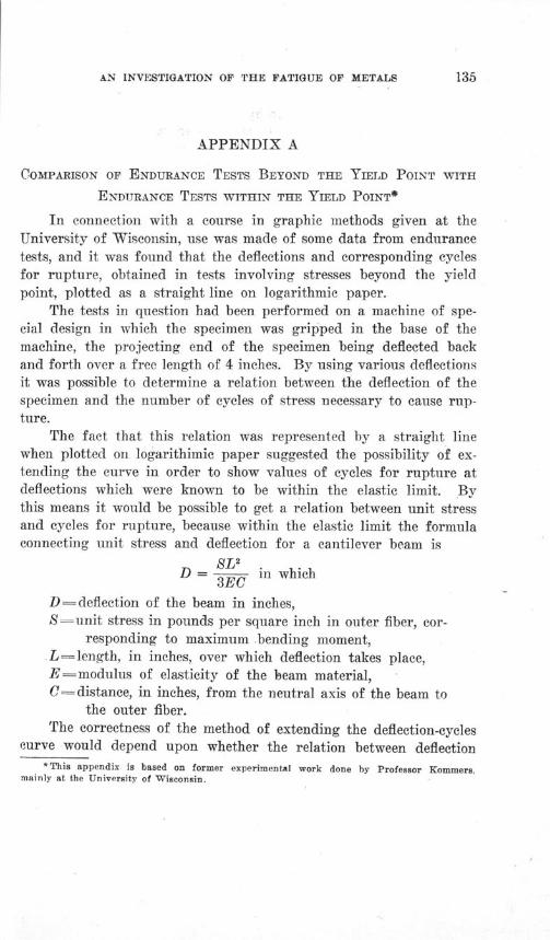
AN INVESTIGATION OF THE FATIGUE OF METALS
APPENDIX A
COMPARISON OF ENDURANCE TESTS BEYOND THE YIELD POINT WITH
ENDURANCE TESTS WITHIN THE YIELD POINT*
In connection with a course in graphic methods given at theUniversity of Wisconsin, use was made of some data from endurancetests, and it was found that the deflections and corresponding cyclesfor rupture, obtained in tests involving stresses beyond the yieldpoint, plotted as a straight line on logarithmic paper.
The tests in question had been performed on a machine of spe-cial design in which the specimen was gripped in the base of themachine, the projecting end of the specimen being deflected backand forth over a free length of 4 inches. By using various deflectionsit was possible to determine a relation between the deflection of thespecimen and the number of cycles of stress necessary to cause rup-ture.
The fact that this relation was represented by a straight linewhen plotted on logarithimic paper suggested the possibility of ex-tending the curve in order to show values of cycles for rupture atdeflections which were known to be within the elastic limit. Bythis means it would be possible to get a relation between unit stressand cycles for rupture, because within the elastic limit the formulaconnecting unit stress and deflection for a cantilever beam is
SL sD = L in which
3EC
D deflection of the beam in inches,S=unit stress in pounds per square inch in outer fiber, cor-
responding to maximum -bending moment,-= length, in inches, over which deflection takes place,
E= modulus of elasticity of the beam material,C= distance, in inches, from the neutral axis of the beam to
the outer fiber.The correctness of the method of extending the deflection-cycles
curve would depend upon whether the relation between deflection* This appendix is based on former experimental work done by Professor Kommers,
mainly at the University of Wisconsin.

ILLINOIS ENGINEERING EXPERIMENT STATION
and cycles for rupture as found by tests beyond the yield point held
also within the yield point. If this proved to be the case, there
would be available a method of establishing the relation between any
unit stress within the elastic limit, and the number of cycles at this
stress which would cause failure. The practical value of this pro-
posed method would lie in the fact that the deflection-cycles curve
could be determined in a few hours, thus rendering unnecessary the
time-consuming methods ordinarily employed in establishing the re-
lation between unit stress and cycles for rupture.
In order to prove or disprove the correctness of the proposed
method it was decided to make tests on a series of three steels vary-
ing in carbon content, determining first the relation between deflec-
tion and cycles for rupture by tests beyond the yield point. The
resulting deflection-cycles curve, plotted on logarithmic paper, would
then be extended or extrapolated, and by means of the formula
connecting unit stress and deflection a relation between unit stresswithin the elastic limit and cycles for rupture would be determined.
A series of reversed-stress tests on a rotating-beam specimen wouldthen be made to determine by direct experiment the actual relationexisting. If these two methods gave the same value for the relationbetween these quantities, it could be considered that the proposedmethod was justified.
Table 9 gives the chemical analysis of the material used in thetests. It was received in the form of 7/ 8-inch rounds. Steel No. 1was annealed at 850 degrees C. for one half-hour, and steels Nos. 2and 3 were annealed at 800 degrees C. for one half-hour. The ten-sile strengths of the steels are given in Table 10.
TABLE 9
CHEMICAL ANALYSES OF STEELS FOR SPECIAL SERIES OF TESTS IN THE
WISCONSIN ROTATING-BEAM TESTING MACHINE
Steel No. Carbon Manganese Silicon
1 0.42 0.59 0.072 0.56 0.55 0.083 0.80 0.51 0.12
Sulphur
0.0310.0350.036
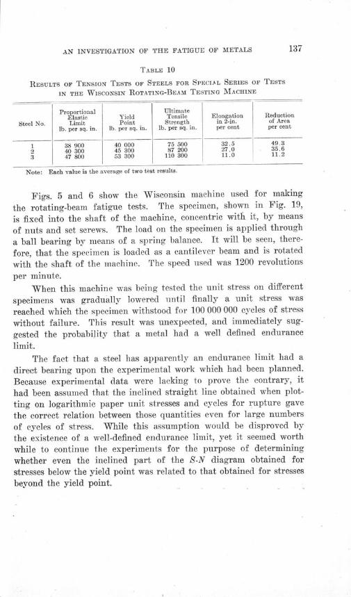
AN INVESTIGATION OF THE FATIGUE OF METALS
TABLE 10
RESULTS OF TENSION TESTS OF STEELS FOR SPECIAL SERIES OF TESTS
IN THE WISCONSIN ROTATING-BEAM TESTING MACHINE
Proportional UltimateElastic Yield Tensile Elongation Reduction
Steel No. Limit Point Strength in 2-in. of Area
lb. per sq. in. lb. per sq. in. lb. per sq. in. per cent per cent
1 38 900 40 000 75 500 32.5 49.3
2 40 300 45 300 87 200 27.0 35.6
3 47 800 53 300 110 300 11.0 11.2
Note: Each value is the average of two test results.
Figs. 5 and 6 show the Wisconsin machine used for making
the rotating-beam fatigue tests. The specimen, shown in Fig. 19,
is fixed into the shaft of the machine, concentric with it, by means
of nuts and set screws. The load on the specimen is applied through
a ball bearing by means of a spring balance. It will be seen, there-
fore, that the specimen is loaded as a cantilever beam and is rotated
with the shaft of the machine. The speed used was 1200 revolutions
per minute.
When this machine was being tested the unit stress on different
specimens was gradually lowered until finally a unit stress was
reached which the specimen withstood for 100 000 000 cycles of stress
without failure. This result was unexpected, and immediately sug-
gested the probability that a metal had a well defined endurance
limit.
The fact that a steel has apparently an endurance limit had a
direct bearing upon the experimental work which had been planned.
Because experimental data were lacking to prove the contrary, it
had been assumed that the inclined straight line obtained when plot-
ting on logarithmic paper unit stresses and cycles for rupture gave
the correct relation between those quantities even for large numbers
of cycles of stress. While this assumption would be disproved by
the existence of a well-defined endurance limit, yet it seemed worth
while to continue the experiments for the purpose of determining
whether even the inclined part of the S-N diagram obtained for
stresses below the yield point was related to that obtained for stresses
beyond the yield point,
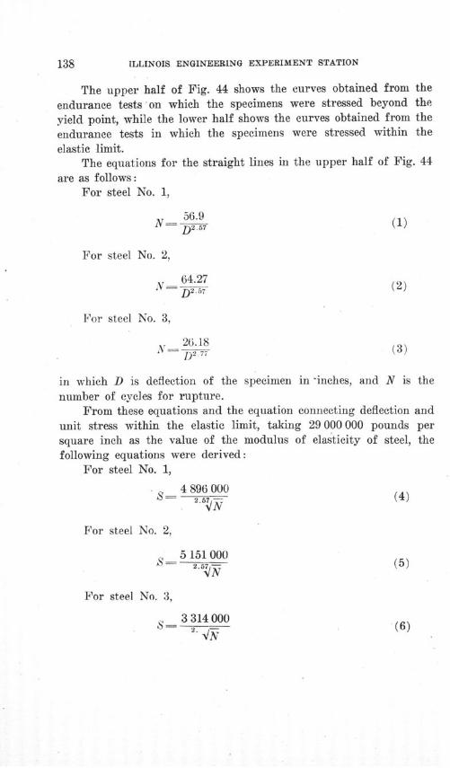
ILLINOIS ENGINEERING EXPERIMENT STATION
The upper half of Fig. 44 shows the curves obtained from the
endurance tests on which the specimens were stressed beyond the
yield point, while the lower half shows the curves obtained from the
endurance tests in which the specimens were stressed within the
elastic limit.The equations for the straight lines in the upper half of Fig. 44
are as follows:For steel No. 1,
56.9Ný D257 (1)
For steel No. 2,
64.27N- D (2)
For steel No. 3,
26.18N- D, 7 (3)
in which D is deflection of the specimen in -inches, and N is thenumber of cycles for rupture.
From these equations and the equation connecting deflection andunit stress within the elastic limit, taking 29 000 000 pounds persquare inch as the value of the modulus of elasticity of steel, thefollowing equations were derived:
For steel No. 1,
4 896 000S- 2.5 (4)
For steel No. 2,
5 151 000- .5 (5)
For steel No. 3,
' 21a4 nni
VAS. 2
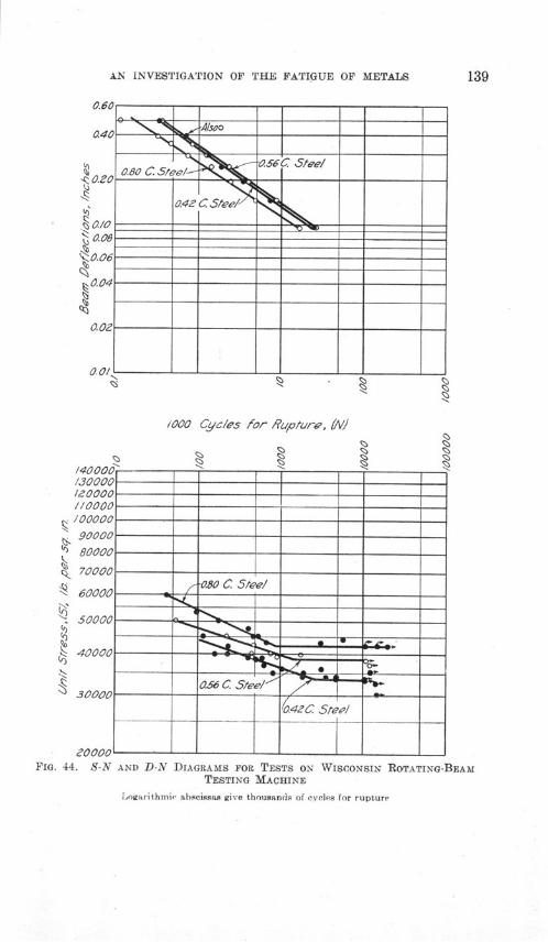
AN INVESTIGATION OF THE FATIGUE OF METALS
/000 Cycles for Rupture, (N)
130000 -
/10000//000 --- -- --- -- --- -
9000 -- ---80000 - ---70000 -- - -
10.80 C S/eel60000 -- ----
50000 -.
40000"- -
056 C Steel/,
04C Steel
,0000 --
0~
FIG. 44. S-N AND D-N DIAGRAMS FOR TESTS ON WISCONSIN ROTATING-BEAMTESTING MACHINE
Logarithmic abscissas give thousands of cycles for rupture
/30000
I
I•0000//0000
c•

140 ILLINOIS ENGINEERING EXPERIMENT STATION
in which S is the unit stress in pounds per square inch, and N isthe number of cycles for rupture.
Table 11 gives certain values of N and the corresponding valuesof S computed from these equations, and also for purposes of com-parison values of S obtained from long-time endurance tests cor-responding to the lower half of Fig. 44.
TABLE 11
COMPARISON OF COMPUTED VALUES AND ACTUAL VALUES OF STRESS FOR
SPECIAL SERIES OF TESTS IN THE WISCONSIN ROTATING-BEAM TESTING
MACHINE
Steel No. 1 Steel No. 2 Steel No. 3N
ComputedS
50 000 72 700100 000 55 500500 000 29 700
1 000 000 22 7002 000 000 17 3003 000 000 14 800
Actual Computed
76 50044 000 58 40038 500 31 20036 500 23 80034 500 18 20033 500 1 15 500
Actual Computed Actual
.... . 63 600 58 30043 000 51 900 54 00038 000 29 000 44 80036 800 22 600 42 00034 800 17 600 42 00033 800 15 200 42 000
This table makes it quite clear that even that part of the S-Ncurve between the endurance limit and the yield point cannot bepredicted from equations such as (4), (5), and (6), derived fromshort-time tests beyond the yield point. It is evident, therefore, thatthe relation existing between deflection and cycles for rupture forstresses beyond the yield point is different from that existing withinthe yield point. Furthermore, calculation shows that there is noconstant relation between the computed and the actual values of Sgiven in Table 11. It is also impossible to make the computed valuesof S agree with the actual values by changing the exponent of Nin the equations, for calculation shows that an exponent that willmake the values agree for a value of N==50 000 will not do so fora value of N= 3 000 000.

AN INVESTIGATION OF THE FATIGUE OF METALS
APPENDIX B
FATIGUE PHENOMENA IN METALS
The following pages give the substance of a progress report pre-
pared by the Engineering Division of the National Research Council
Committee on Fatigue Phenomena in Metals and published in "Me-
chanical Engineering" for September, 1919.
This committee of the National Research Council was made the
Advisory Committee for the Joint Investigation of the Fatigue of
Metals. Those paragraphs of the 1919 progress report which deal
with plans for an investigation of fatigue phenomena in metals are
not printed here, since they are given in substance either in the
parts of this bulletin dealing with test results or in Chapter VI,
"Subjects for Further Investigation." It should be remembered
that the progress report given in this appendix was written before
the main part of the bulletin, and that it is to be expected that the
results of the investigation will be found to modify some of the
views given in the first progress report.
In this appendix references are made by number to articles
listed in the Bibliography given in Appendix D.
Metal parts of machines, such as springs, shafts, crankpins, and axles,
occasionally fail suddenly while only subjected to conditions of ordinary service.
Not only does failure occur suddenly, but the part about to fail shows no ordi-
nary evidence of weakness. The broken parts when examined are seen to be
broken off short, and without general distortion, even though the material may
show high ductility in ordinary tests. Such failures are found only in parts sub-
jected to stress repeated many times-to "vibration," as it is sometimes
stated-and the phenomena which are involved in the final failure of metal
through oft-repeated loading are known as "fatigue" phenomena of metals.
The phenomena of fatigue failure have recently given rise to some pre-
plexing problems in connection with the design and service of airplane-engine
crankshafts, the hulls of steel ships, axles and shafts in railway cars, motor cars
and trucks, and other machine parts. The question whether structural parts
subjected to repeated stress are in danger of fatigue failure has been discussed
at considerable length. The danger of fatigue failure seems to be an unim-
portant factor in determining the safety of structural parts, with the possibleexception of parts subjected to reversal of stress. The reason for this is prob-ably found in the relatively small number of loadings which most structures are

ILLINOIS ENGINEERING EXPERIMENT STATION
called upon to withstand, and in the fact that most of the loadings are belowthe maximum working value. On the other hand, the danger of fatigue failureis a major factor in determining the safety of many machine parts.
The problem of fatigue of metals engaged the attention of engineersseventy years ago, in connection with car axles and members of iron railwaybridges. It was early recognized that high stress tends to cause, or at least tohasten, fatigue failure, and about 1860 W6hler's famous investigations 132(b)were undertaken to determine the relation between intensity of fiber stress andthe ability of materials to resist fatigue under repeated stress. Wohler's testsoccupied some eleven years, and remain to this day the most thorough tests onrecord. WShler investigated metals under direct tension, under bending, andunder torsion (shear). For some of his tests the stress varied from zero to amaximum and for others the stress was reversed. The results of Wahler's testsmay be summarized as follows:
(1) A machine part or structural member may be ruptured by the repeatedapplication of a load which produces a computed fiber stress less thanthe ultimate strength of the material as determined by a static test.
(2) The greater the range of stress, the lower the limiting fiber stress to in-sure against rupture after a very large number of repetitions.
(3) To insure against rupture after a very large number of repetitions of load-ing causing complete reversal of stress, the limiting fiber stress isbut little greater than one-half the limiting fiber stress for a verylarge number of repetitions of stress varying from zero to a maximum.
Following Wohler the famous Bauschinger9 published a series of conclusions onfatigue, and various other investigators, notably Gerber,12(b) and Weyrauch andLaunhardt,6s(d) gave early interpretations of the experimental results of Wbhlerand Bauschinger.
In these earlier experiments several facts seem noteworthy. The primeobject of the investigators was to deduce laws of fatigue for railway bridgesand car axles. The problem of fatigue in high-speed machine parts had notthen appeared. These investigators carried their tests far enough to cover thenumber of repetitions required by the structures of their day and assumed thathaving done so they had established an endurance limit. Reading their con-clusions carefully, the statement does not seem to be made that material whichpassed their tests would stand an infinite number of repetitions. The termgenerally used is "indefinite" or "very large," and the number correspondingis from ten to fifty millions. For the problem which they investigated theirtests seem to give safe guides for practice, but today, with the advent of modernhigh-speed machinery, some parts of which must be as light as possible, andthe extension of the fatigue problem to such members as the cranks and theconnecting rods of gas engines and the shafts of steam turbines, the numberof repetitions of stress which a machine member may be called upon to undergois very much increased. This fact is illustrated by Table 12, which gives astatement of the approximate service required from various structural andmachine members.

AN INVESTIGATION OF THE FATIGUE OF METALS 143
Investigations have been made in recent years by Howard,56 Stan-ton,112, 113, 14, 115 Basquin,s Smith,l07 Eden, Rose and Cunningham,28 Kommers,6s
Mason,74 Moore and Seely,8 3 and others. The efforts of these investigators
TABLE 12
APPROXIMATE SERVICE REQUIRED OF VARIOUS MEMBERS OF STRUCTURES
AND MACHINES SUBJECTED TO REPEATED STRESS
Approximate NumberPart of Structure or Machine of Repetitions of Stress
in the "Lifetime" of theStructure or Machine
Railroad bridge, chord members .................................... 2 000 000Elevated-railroad structure, floor beams........... .................. . 40 000 000Railroad rail, locomotive wheel loads ............................ . .. . 500 000Railroad rail, car wheel loads ...................................... . 15 000 000Airplane-engine crankshafts ..................................... .. 18 000 000Car axles ... ..................................................... 50 000 000Automobile-engine crankshafts...................................... 120 000 000Lineshafting in shops.. .......................... ............ .. 360 000 000Steam engine piston rods, connecting rods and crankshafts.............. 1 000 000 000Steam-turbine shafts, bending stresses .............................. 15 000 000 000
have been toward the study of modern materials, refinements in methods of
testing, and interpretation of results. The limits of actual tests have not beenextended to modern requirements, and the problem still remains of obtaining
test data for much longer endurance of fatigue than was contemplated byWohler. Under the most favorable conditions conceivable such data will beobtained very slowly, and meanwhile there must be faced the problem of de-termining safe stresses for very large numbers of repetitions by extrapolationfrom previous test results.
MACHINES FOR TESTING FATIGUE STRENGTH
Fatigue tests cannot readily be carried out with ordinary ''static'' testingmachines. It is, of course, possible to repeat loadings on a test specimen insuch a machine, but the process is very slow. Such a machine equipped with aningenious automatic arrangement for applying and releasing load was used byVan Ornuml 2 8 in fatigue tests of concrete in compression, but the time requiredfor even a hundred thousand cycles of stress was very great.
A very simple repeated-stress testing machine acts by the application andremoval of a weight to the end of the long arm of a simple or compound lever,the specimen carrying load at the short arm. Such a machine was used byBerry in fatigue tests of concrete in compression. In a machine of this typethe load must be applied slowly, else there will be inertia forces set up by theimpact of the weight as it is let into place.
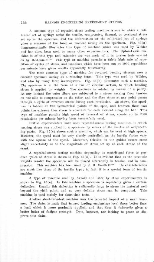
ILLINOIS ENGINEERING EXPERIMENT STATION
A common type of repeated-stress testing machine is one in which a cali-
brated set of springs resist the tensile, compressive, flexural, or torsional stress
set up in the specimen, and the deformation of the calibrated set of springs
gives a measure of the force or moment acting on the specimen. Fig. 45(a)
diagrammatically illustrates this type of machine which was used by W6hler
and has since been used by many other experimenters. The Upton-Lewis ma-
chine is of this type and extensive use was made of it in torsion tests carried
on by McAdam.s 1(b) This type of machine permits a fairly high rate of repe-
tition of cycles of stress, and machines which have been run at 1000 repetitions
per minute have given results apparently trustworthy.
The most common type of machine for reversed bending stresses uses a
circular specimen acting as a rotating beam. This type was used by Wohler,
and also by many later investigators. Fig. 45(b) illustrates such a machine.
The specimen is in the form of a bar of circular section, to which bending
stress is applied by weights. The specimen is rotated by means of a pulley.
At any instant the outer fibers are subjected to a stress varying from tension
on one side to compression on the other, and the fiber stress at any point passes
through a cycle of reversed stress during each revolution. As shown, the speci-
men is loaded at two symmetrical points of the span, and between these two
points the extreme fiber stress is constant for each element along the bar. This
type of machine permits high speed of reversal of stress, speeds up to 2000
revolutions per minute having been successfully used.
British experimenters have used repeated-stress testing machines in whichvarying stress was applied to a specimen by means of the inertia of reciprocat-
ing parts. Fig. 45(c) shows such a machine, which can be used at high speeds.
However, the speed must be very closely controlled, as the inertia forces vary
with the square of the speed. Moreover, friction on the guides causes someslight uncertainty as to the magnitude of stress set up at each stroke of thecrank.
A repeated-stress testing machine depending on centrifugal force to pro-
duce cycles of stress is shown in Fig. 45(d). It is evident that as the eccentricweights revolve the specimen will be placed alternately in tension and in com-pression. This machine has been used by J. H. Smith.o107(" Its characteristicsare much like those of the inertia type; in fact, it is a special form of inertiamachine.
A type of machine used by Arnold and later by other experimenters isshown in Fig. 45(e). In this machine a specimen is repeatedly given a certaindeflection. Usually this deflection is sufficiently large to stress the material wellbeyond the yield point, and no very definite stress can be computed. Thismachine is used mainly for short-time tests.
Another short-time-test machine uses the repeated impact of a small ham-mer. The claim is made that impact loading emphasizes local flaws better thana load which is more gradually applied, and that thus it indirectly gives abetter index of fatigue strength. Data, however, are lacking to prove or dis-prove this claim.
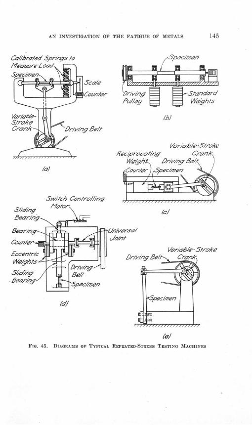
AN INVESTIGATION OF THE FATIGUE OF METALS
Ca//hrated Spr/Iys to
(c)
V/a'r/ab/e - Strolke
(elFIG. 45. DIAGRAMS OF TYPICAL REPEATED-STRESS TESTING MACHINES
(ri'ng •St^ dard
Pul//ey/ Weights
(b)
Var/'ab/e -5trokeRec'procan'/ny C2an/
Wi/ath& Dr/di-:y de/l /
^Contr ioe/e < ^
Sw/t/ch Contro//ing
ILLINOIS ENGINEERING EXPERIMENT STATION
Various repeated-stress testing machines have been constructed in whichthe cycles of stress were set up by the action of an electromagnet energized byalternating current. Usually the stress was measured either by the deflectionof a spring or by the deformation of a standard test bar attached to the speci-men. The speed of such a machine, however, is usually so high that there seemsto be some uncertainty as to whether the successive waves of stress pass throughthe specimen without interference.
While the microscope can hardly be classified as a testing machine, it has,nevertheless, been of such vital importance in studying fatigue phenomena thatit may well be mentioned in this place. Space will not permit of a detaileddescription of the methods employed in the microscopic examination of metals,but the process involves polishing a small area of the metal, etching the surfacewith some reagent to bring out the lines of the crystalline structure, and ex-amining and photographing the surface through a microscope, the surface ofthe metal being illuminated by means of a reflected light.
THE PHENOMENA OF FATIGUE FAILURE
A fatigue failure of a metal, whether it occurs in a test specimen or ina machine part, is characterized by suddenness, lack of warning, apparent brit-tleness of material, and, in many cases, a fracture with a crystalline appearanceover a part of its surface.
This crystalline appearance led to the old theory that under repeated stressmetal "crystallized," changing from a ductile "fibrous" structure to a brittle"crystalline" one. This theory, however, has been quite thoroughly demolishedas a result of study of the structure of steel under the microscope. As revealedby the microscope the structure of all metals used for structures and machinesis crystalline, any "fibrous." structure being caused by inclusions of non-metallicimpurities (for example, slag in wrought iron). Microscopic examination ofmetals under stress shows no change of the general scheme of internal structure,but under sufficiently heavy stress there appears gradual breakdown of thecrystals in the structure.
When a ductile metal is deformed cold, the first deformation occurs inthe particular grains which either take the most stress or have the lowest elasticlimit. Deformation takes place by the slipping of one portion of the grain withreference to other portions. This slipping is shown by the appearance of linescalled "slip bands" or "slip lines" extending across crystals and indicatingplanes of cleavage, as shown in Fig. 46. As the load is increased deformationproceeds and other slip bands are formed, the law being that the most easilydeformable grains first show slip bands. Gradually the most favorable planesof slip are exhausted, and further slippage can take place only with the addi-tion of more load.
The failure in ductile metals subjected to repeated stress takes place withsubstantially no general deformation. There is, however, considerable localdeformation over microscopic areas, evidenced by the appearance of many slip

FIG. 46. MICROGRAPH SHOWING SLIP LINES IN IRON
Magnification 80 diameters


AN INVESTIGATION OF THE FATIGUE OF METALS
bands on a polished surface of the metal after the application of repeated stress.
These slip bands appear after a small number of reversals of stress with rela-
tively large loads, and may not appear at all with slight loads. The slip bands
may first appear either in the interior of a grain or at the grain boundary. As
the number of applications of stress increases more slip bands appear, and those
first appearing usually lengthen and widen. Under the microscope and with
normal illumination the general surface becomes blacker as the number and
width of the slip bands increase. In ductile metals fatigue failure is almost
exclusively through the grains themselves rather than at the grain boundaries,and the first slip bands to appear do not necessarily form a part of the final
path of rupture. Failure seems to take place by the uniting of slip bands into
cracks. When the first grain develops a crack extending across its entire width,added stress promotes the extension of this crack into adjacent grains on both
sides, although the orientations of these grains may be and usually are such
that the crack must extend itself at an angle to that in the initial grain. The
general tendency is for these slip bands to follow the lines of cleavage of theparticular grain in which they occur. Often incipient fracture is found in many
grains adjacent to the final path of rupture, indicating that had rupture not
taken place where it did, it would have soon taken place in some other adjacent
part.
Such observations by means of the microscope indicate that localizeddeformation is the primary cause of fatigue failure in ductile metals, but itdoes not necessarily follow that the formation of one slip band under repeatedstress will indicate eventual fracture if the loading is continued; one grain mayappear to have a greatly reduced elastic limit because of internal strains orpeculiarly unfavorable orientation. It is not certain that there is a limitingload below which fatigue will never take place.
Materials classified as brittle have very little permanent deformation understatic stress, and under repeated stress the progressive fracture of brittle ma-terial might take place, not by slipping within crystals, but by tensile fractureof crystals. There has been practically no study made of the fracture of brittlematerials under repeated stress, and it would be instructive to have tests carriedout on brittle amorphous materials such as fused silica and on brittle crystal-line materials like marble or tungsten. It is gradually being recognized thatthe breaking load of a specimen is a complex matter, and depends, among otherthings, on the time of application of the load. Mere duration of static load-ing, however, does not have an effect at all comparable with repetition of load-ing in reducing the breaking load. It seems evident that the distribution ofstress in some brittle materials is very much less uniform than in ductile ma-terials, and that fractures in brittle materials start on areas of high stress,whereas in ductile materials the high stresses are relieved by local yielding. Amore complete understanding of the mechanism of rupture in brittle materialswould doubtless be of great value.
When the action of metal under repeated stress is considered from theviewpoint of the internal strains and accompanying stresses in the material, a

ILLINOIS ENGINEERING EXPERIMENT STATION
radical difference is seen in the behavior of material under static load and underrepeated load. In a general way we may consider any structural or machinepart as subjected to static conditions if the load on it is applied gradually andis not repeated more than a few hundred times; the part may be considered assubjected to fatigue if the load on it is applied, say, one hundred thousandtimes or more; and for intermediate conditions of loading the phenomena charac-teristic of both kinds of loading would be present.
We must look upon steel as filled with a multitude of minute flaws. Theseflaws are developed in the solidification of the material. In static testing, steelunder stress of about half its ultimate strength passes into a semi-plastic con-dition, in which there is a gradual flow of the material. Under such conditionsthe small flaws have almost no effect upon the flow or upon the static strength.When steel is loaded to moderate stresses the yielding is almost entirely elastic,but in general a small portion of it is inelastic, energy being taken up by thesteel itself. If the specimen can be loaded a great number of times withoutheat loss its temperature will increase. If it is set vibrating in a chamber freefrom air it will stop vibrating in a short time, due to the absorption of energy.In such cases the stress-strain curve appears to'be straight and the curve forthe removal of the load may be practically identical with that for the applica-tion of load, but still these other effects show loss of energy in the steel itself.
This loss of energy is doubtless due to small displacements at these flaws,which are not reversible. Under alternate loadings these displacements are madeback and forth. Energy is continuously being absorbed in the location of thesesmall flaws, and it is perfectly natural that they should increase in size. Wemust look upon these extensions of the flaws as occurring in a great many partsof the steel. If the stresses are small the increase in size of these flaws is prac-tically negligible, but if the stresses are larger the increase is rapid, and lateron in the history of the piece under test, very rapid, and finally the strength ofthe piece is terminated when a sufficient number of these flaws have connectedso as to form an area of very great weakness.
For static loads all the above is of little consequence with a ductile metal;but it is of consequence in the case of a brittle metal like cast iron, which hasa remarkably low strength in tension in comparison with its compressive strength.Ductile metals may be considered as having a very high value for cohesion witha rather low coefficient of friction-or whatever corresponds to that-so thatthese metals begin to slide on diagonal planes without actual fracture underhigh local stress.
When a ductile material is loaded it may be subjected to stresses whoseaverage values for small areas are not very different for parts that are a tenthof an inch apart; but there is a multitude of tiny spots whose fiber stressesare 2, 3, 4, or 10 times the average value, 61, 92 2 1 (". This holds so long aselastic conditions obtain. As the applied stress increases some of these stressesincrease in like ratio, but not in like increments. At moderate applied stressesthese special stresses reach inelastic conditions and slipping occurs. If theaverage stress is now entirely removed, we may assume that the unloading takes
AN INVESTIGATION OF THE FATIGUE OF METALS
place in a similar manner. The small spots unload first in an elastic manner,but at a different rate than the remainder of the material. They will unloadapproximately at the same rates as they used in taking stress, namely, 2, 3, 4,or 10 times the normal rate. For the unloading they have about twice therange of stress that they had in the loading before inelastic action is set up.Some of them will reach the opposite limit and slip part way back again, whilesome of them may not be subject to this return slip of inelastic action, but willretain in the unloaded state a stress distribution of the opposite kind. Eitherof these actions will give rise to hysteresis and to slight change of dimensions,usually, however, too small to be detected.
. In all of the foregoing the main parts of the material have not been sub-jected to stresses which give inelastic action. If the loading is repeated with-out reversal, the spots that slipped on the first unloading will be subjected tofurther slipping both on loading and on unloading, but the areas that sufferedno slipping on the first unloading should show no further inelastic action un-less the loading is reversed. If the loading is reversed, however, all the particlesthat slipped in the first loading will slip on the reverse loading, so that withrepetition a larger number of spots undergo this slipping action than is thecase with loading which is not reversed. This explains the shorter life underreversed stress than under repeated stresses in one direction only.
If the fractured surface of a "rotating beam" specimen made of ductilemetal and broken by repeated stress is examined, it is usually seen to be madeup of two parts: (1) near the extreme fibers there is a dark surface with adull, lusterless appearance, while (2) the remainder of the surface has a brightcrystalline fracture. If these are examined more carefully it is found that theirprincipal difference is in the size of the small flat surfaces that constitute thefracture. The center portion of the area has comparatively large surfaces, giv-ing a crystalline effect, while the dull gray portion has very small surfaces offracture.
An explanation of this is that the flaws in the outer portion of the sur-face have connected to form an annulus, whose rugged face is roughly at rightangles to the axis of rotation. This has doubtless occurred slowly, and hasstarted from many centers, thus giving the rough face. After this slow growthof flaws into an annular fracture has been accomplished the specimen has be-come very weak and the stresses have become so large at the fracture that theysuddenly tear the metal in two on the natural surfaces of cleavage of the crystalgrains.
The center portion of this fractured surface does not differ from the crys-talline surface at the bottom of a cup in an ordinary static tension fracture,except that the crystalline surfaces are somewhat larger. This is to be explainedby the fact that in an ordinary tensile test the material at the fracture haselongated something like 100 per cent, so that the crystal grains have becomeof smaller cross-section and will naturally show smaller facets on fracture,whereas, in a fracture of the endurance specimen, the material has had no chanceto elongate and the crystalline grains have their normal size, which will be
ILLINOIS ENGINEERING EXPERIMENT STATION
shown in fracture. It is not the crystalline portion of the broken specimen
which has failed primarily by repeated stress, but the dull portion. In the
crystalline part of the fatigue fracture and in the crystalline part of the static
tension fracture the failure seems to be of the same nature, namely, a failure in
cohesion.
In considering the phenomena of fatigue failure it may be well to call at-
tention to the fact that there is an intermediate type of failure of ductile material
in which both plastic action and the development and spread of microscopic flaws
are present. Such failures sometimes occur in staybolts, boiler sheets between
rivet holes, and other parts occasionally subjected to very severe local distortion.
LOCALIZED STRESSES UNDER STATIC LOADING AND UNDER IMPACT LOADING
When a machine member or structural part is loaded gradually a state of
strain and accompanying stress is set up throughout it. In a general way the
distribution of stress is similar to that given by the theory of elastic action
which serves as a basis of our formulae for computing stress and strain. There
are, however, many deviations from this distribution due to non-homogeneity of
the material and to irregularities in outline such as projecting corners, scratches,
and tool marks. When load is applied the general behavior of the piece as
indicated by careful measurements of stretch, compression, twist, or flexure
conforms to that required by the common theory of elastic action, but there
are doubtless many localized strains which cannot be detected, even by the use
of delicate micrometer measurements. It is to be recalled that in measuring
strains it is necessary to use a gage line of considerable length, with the result
that the observed strain is an average value along a relatively long line. The
localized stresses, corresponding to these undetected localized strains, are not
of any great importance under static load. When the load is increased to such
an extent that a considerable portion of the piece is stressed beyond the elastic
limit, the distortion of the piece increases abnormally and the piece may be
considered to have reached its yield point. After this limit is passed the dis-
tribution of stress is much modified, and for parts made of ductile material the
abnormal distortion at the yield point usually gives warning of structural dam-
age before complete failure occurs.
Under impact loading, which is merely loading applied in a very short
space of time, the action is somewhat similar to that under static loading, except
that ductile material may offer a higher resistance to very rapid fracture than
it does to fracture occurring gradually through a period of several minutes.Impact fracture, moreover, may emphasize somewhat the localized stresses set
up at places where the structure of the material is non-homogeneous, or atplaces where there are sharp notches or deep scratches in the surface of thepiece. Under slowly applied load there is opportunity for considerable adjust-
ment and equalization of stress after the yield point is passed; under impactload there is probably less equalization on account of the rapidity of the action,

AN INVESTIGATION OF THE FATIGUE OF METALS
and hence the localized stresses are higher and more effective in causing failure.
This explanation of the action under impact is given here because repeated
stresses also emphasize the effect of high localized stress, though for an entirely
different reason.
TESTS AND CRITERIA FOR FATIGUE STRENGTH
It was formerly the common opinion that the determination .of the elastic
limit of a material by means of a static test in a testing machine gave a reliable
test for the fatigue-resisting qualities of the material, and that the materialcould withstand an infinite number of repetitions of stress lower than this elasticlimit. Tests at various laboratories, however, have quite thoroughly disprovedthis idea, and have thrown grave doubts on the reliability of the elastic limitas an index of fatigue strength. The term "elastic limit" has always beenrather loosely used, and covers several quite different stresses.79(a> The valuedetermined for the elastic limit for any material depends on the sensitivenessof instruments used and the accuracy of plotting results, and the elastic limitas determined by such a test in a testing machine is determined by the averagebehavior of the material over a considerable length, while the process of fatiguefailure may be going on over a section so small that it does not appreciablyaffect the readings of the measuring instruments used. In several laboratoriescomparative repeated-stress tests of different materials have shown higher fa-tigue resistance for the material with the lower elastic limit. 23, 80, 82
Bauschinger in his classic experiments showed that the elastic limits intension and compression as determined by ordinary testing-machine tests werevariable limits, their value depending on the treatment of the material duringfabrication. He called such limits "primitive" elastic limits, and showed thatwhen a specimen is subjected to gradually increasing range of alternating stressthere are soon set up two elastic limits in the bar-one in tension and one incompression. He called these limits, which may have values widely differentfrom the "primitive" elastic limit, the "natural" elastic limits, and the rangebetween them the "elastic range." He also showed that a test specimen willstand several million repetitions of this elastic range of stress without failure,and proposed the "natural" elastic limits as indices of the fatigue-resistingstrength of the material. J. H. Smith'07o> has developed a somewhat simplifiedprocess of determining the elastic range. This elastic range seems a morereliable index of fatigue strength than the ordinary "primitive" elastic limit,but the reliability of indices of fatigue strength based on determinations ofany elastic limit by testing-machine tests is open to question on account of thepossibility that localized fatigue failure may be in progress without affectingthe readings of the instruments used in static tests.
W6hler used as an index of fatigue strength the "endurance limit" ofmaterial as determined from a series of fatigue tests with different intensitiesof stress. He used the method of plotting values of stress (S) against numbers
ILLINOIS ENGINEERING EXPERIMENT STATION
of repetitions required for fracture (N) and determining by eye where this S-Ncurve became "practically horizontal." Other investigators have plotted valuesof S against values of 1/N or of (1/N) n and by extending the diagram till itintersected the axis of ordinates have determined an assumed endurance limit foran infinite number of repetitions of stress. Both of these methods involve enor-mous extrapolation of test data. Moreover, widely different endurance limitscan be determined from the same test data by different methods of plottingvalues.83 The tendency to irregularity of test results under low stresses makesthe decision whether the S-N curve is horizontal or slightly sloping downwardone of very considerable uncertainty.
It has been proposed by various experimenters to compare the fatigue-resisting qualities of different metals by short-time tests with stresses well be-yond the yield point of the material. Such tests are quickly and easily made.Under such stresses, however, the action of the material is partly a plastic flow.Such tests give good promise of determining fatigue strength and toughnessunder occasional overload for parts such as staybolts, which in their ordinaryservice are subjected to rather severe distortion, but it is not at all certain thatsuch tests give a reliable index of resistance of machine parts under ordinaryworking stresses.so
It has been proposed by various laboratories to compare the fatiguestrengths of various materials by comparing their life under repetitions orreversals of some standard stress, usually less than the elastic limit of thematerial as determined by a static test. A somewhat similar standard proposedis to determine the stress which will cause failure under a given number ofreversals. Standard stresses proposed for steel are 38 000 pounds per squareinch (reversal) and 25 000 pounds per square inch (reversal). One million re-versals has been proposed as a standard "life." These two types of testapproach working conditions more closely than do the short-time, high-stresstests described above. However, they determine only one point on a S-N dia-gram for a material and do not indicate how fatigue endurance changes withchange of stress.
A comparative study of fatigue strengths of various materials can bemade from a S-N diagram plotted on logarithmic paper. Up to about 1 000 000repetitions of stress logarithmic S-N diagrams fall quite closely along straightlines, and from the ordinates and slopes of these lines the behavior of materialsunder various intensities of stress can be studied. Tests may conveniently bemade with stresses at about the yield point of the material, at stresses about20 per cent lower, and at one or two intermediate stresses.
Various other possible tests have been proposed for determining the fatigue-resisting strength of a material, but no test has been proved to be of sufficientreliability to be accepted as a standard. A number of tests, however, seemworthy of experimental study.
The rate of dying out of vibrations in a "tuning fork" specimen of thematerial has been suggested as a possible index of fatigue strength.15 It isassumed that the gradual dying out of vibration is due largely to loss of energy

STIGATION OF THE F
F METALS
.AIN N VJ
spent in inelastic action in the material, and that such inelastic action is a
measure of the fatigue weakness of the material. Test data are lacking to deter-
mine the value of this test, but it seems worthy of study.
Tests of magnetic permeability have also been proposed to locate internal
flaws in the material and thus indicate its relative fatigue strength. The entire
subject of the correlation of the magnetic and the mechanical properties of iron
and steel is a promising field of investigation.'9
The rise of temperature under repeated stress has likewise been proposed
as a measure of fatigue resistance.1is(b) Theoretically, if a specimen is sub-
jected to reversed elastic stress no change in temperature should take place, and
it has been proposed to determine the endurance limit for metals at that stress
which causes the first noticeable rise in temperature after some, thousand or
more reversals. A practical difficulty in using this test is to secure proper heat
insulation for the specimen. This test seems worthy of study, however, espe-
cially if employed in an inertia type of testing machine (see Fig. 45[c] and [d]).
The detection of the appearance and growth of "slip lines" in a speci-
men subjected to repeated stress gives some promise of furnishing a reliable test
for fatigue strength. Slip lines appear long before fracture occurs, and if their
appearance or the rate of their spread can be shown to be an index of fatigue
strength it seems possible that a feasible laboratory test may be devised. The
search for slip lines over any considerable area would, however, be very tedious.
Impact tests, usually on notched bars in bending, have been proposed as
an index of fatigue strength. The actions under impact failure and under
repeated stress are very different, the first giving a sudden break of the entire
cross-section of the specimen, and the second a gradually developing fracture.
Both failures, however, seem to be affected by localized flaws or irregularities
in outline, and though no definite correlation between fatigue strength and
strength to resist impact has been established, yet such tests are worthy of study.
Repeated-impact tests have also been proposed to determine fatigue strength,
but whether such tests have any advantage over short-time tests under non-
impact loads is not known.In all tests to determine fatigue strength it is of the highest importance
to secure uniformity of surface finish between the different specimens to be
compared. Probably this can best be done by polishing the surface of the
specimens where failure is expected.There is today no short-time test accepted as a standard test for fatigue
strength; but the development of such a test, and the establishment of its
reliability, would unquestionably be of very great service to testing engineers.
LOCALIZED STRESS AND ITS INFLUENCE IN PRODUCING FATIGUE
The ordinary formula and methods of analysis used in computing thefiber stress in a machine part or structural member are based on the assump-tion that the material is homogeneous throughout, and that the cross-section
ILLINOIS ENGINEERING EXPERIMENT STATION
of the member is either constant or that it changes its dimensions so regularlyand gradually that there is no appreciable localized fiber stress at sections of
rapid change. For structures and machines of ductile material subjected to
not more than a few hundred loadings, such assumptions are reliable, because
localized stresses do not appreciably affect the general deformation of a mem-
ber, nor do they under ordinary working conditions cause trouble before the
member has been subjected to some thousand or more repetitions of load. Fornearly all parts, however, high localized stresses are present. Internal flaws maycause such localized ,stresses. This is shown by mathematical analysis of stressin plates with holes in thems1 and by direct experiment on such plates. 92, 21(i
External irregularities of outline may cause localized stress. Under bendingor twisting a member with a sharp reentrant angle in its outline theoreticallydevelops an infinite stress at the root of the angle,29 and actually both mathe-matical analysis and direct experiment show that very high localized stress maybe caused by sharp grooves or scratches on the surface of a machine part orstructural member.
It has been stated above that for parts subjected to a few loadings local-ized stresses are not of great significance. The case is quite different, however,for parts subjected to thousands of loadings. High localized stress may causea crack to start, either directly or by "cold-working" the material where thelocalized stress exists until the material becomes brittle. This crack forms anextension of the discontinuity of the material which caused it, and under re-peated stress tends to spread still more rapidly. This tendency is illustratedby the action of a piece of plate glass in which a crack has started. In mostcases under any repetition of load the crack spreads, and will cause final fractureof the glass. A fatigue failure under repeated stress is a progressive failure.This spreading of cracks to cause failure explains why under fatigue even duc-tile materials snap short off. Failure does not involve plastic flow of consider-able masses of metal, but only of microscopic masses near the crack, and finalfracture comes suddenly just as if the member were cut half off by means of asaw cut and then bent. The importance of avoiding localized high stress inmembers subjected to repeated stress can hardly be overemphasized. Homo-geneity of internal structure, smoothness of external surface, and avoidance ofsudden changes of cross-section may be more important in the construction ofmachine parts subjected to repeated stress than is high static strength of material.
Shoulders of crankshafts and of axles, keyways in shafts, screw threads,and rivet holes are examples of locations where high localized stress is liableto occur.
RELATION BETWEEN MICROSCOPIC STRUCTURE AND FATIGUE
A very large field of investigation and one in which very little systematicwork has been done is the study by means of the microscope of fatigue failures invarious characteristic structures of metals, especially steels. The following para-graphs are given as a summary of the theory held by present-day metallogra-

AN INVESTIGATION OF THE FATIGUE OF METALS
phists of the relation of microstructure of metal to its fatigue strength. Many
of the details of this theory, however, lack adequate experimental verification.
Annealed steel consisting of ferrite (pure iron) and cementite (iron car-
bide, Fe C) seems to increase in resistance to fatigue with the increase in carbon
content, especially when the cementite is present in the form of plates as in
lamellar pearlite and as long as the cementite does not surround the grains
of pearlite. When the cementite is spheroidized, the elastic limit is greatly de-
creased and probably the resistance to fatigue is also decreased. As a structural
material, therefore, a steel with considerable carbon in the form of spherical
globules of iron carbide would have practically no advantages over wrought iron.
When, however, the iron carbide is in plates it seems to have a marked effect in
raising the elastic limit, and probably increases the resistance to fatigue. We
would also expect that complete and large networks of ferrite would lower fa-
tigue resistance.The same arguments regarding grain size of single constituent metals hold
to a certain extent for two component alloys. For example, such experimental
evidence as is available indicates that the sorbitic structure in steel is the one
which resists fatigue best. This structure is supposed to represent an extreme
refinement of grain in which the particles of iron carbide are very small, and
hence the particles of ferrite must also be very small. It is true that some of
the iron carbide may be in solution in the iron, but it is more probable that the
mechanical properties observed can be accounted for by an extreme reduction
in the size and by the dispersion of ferrite and cementite particles. When these
globules are made larger by heating to a higher temperature than that at which
the sorbite was formed, granular pearlite results with reduced fatigue resistance.
When a high-carbon steel is quenched from above the critical range to
form martensite, the metal becomes extremely brittle. The normal path of
static rupture in brittle martensite is at the old austenite (solid solution of FeaC
in gamma iron) grain boundaries. The path of rupture in fatigue has, so far
as is known, not been ascertained. From certain tests on the resistance to
fatigue of chrome-vanadium steel after various heat treatments, Dr. C. M. Olm-
stead, of the C. M. 0. Physical Laboratories, Buffalo, found that the steel in
the martensitie state, that is, as quenched, had a very much lower resistance
to fatigue than after reheating to about 1100 degrees F. The maximum resist-
ance to fatigue occurred by quenching and reheating to 1000-1200 degrees F.
(538-648 degrees C.), and there was very little difference between the speci-
mens tempered at 1000 degrees and at 1200 degrees. There was a marked dif-
ference, however, between these and the samples tempered at lower tempera-
tures or those not tempered at all. This is the heat treatment that is commonly
given to automobile parts which must withstand fatigue stresses, and which may
be subjected to shock. The tempering of springs is done at a little lower tem-
perature, but it is not certain that the spring structure is the one having the
highest resistance to continued repetition of stresses.
It seems from the above that martensite is not a suitable material to
withstand fatigue stresses, and that some intermediate structure between mar-

158 ILLINOIS ENGINEERING EXPERIMENT STATION
tensite and the annealed or normalized structure will have the maximum resist-ance to fatigue. This structure is called the sorbitic structure and correspondsto that used in automobile springs and other parts of automobiles which mustresist fatigue and shock stresses.
FORMUL2E FOR DESIGNING PARTS SUBJECTED TO REPEATED STRESS
All formulae which have been proposed for designing parts subjected torepeated stress depend upon extrapolation from test results and should there-fore be regarded as tentative. Their use is justified only on the ground ofnecessity. Parts must be designed to resist repeated stress, and even formuladerived from a confessedly inadequate experimental basis seem better than mereguesswork. Two types of formula have been used.68(d),
7 9 ( b )
In many discussions of data of repeated-stress tests, it is assumed thatthere exists some definite "endurance limit," that is, some stress, greater thanzero, which can be repeated an infinite number of times without causing failureof the material. If such a limit exists it is certainly lower than the elastic limitof the material as determined by static tests, for actual failures of materialshave occurred under repeated nominal stresses as low as one-quarter of the elas-tic limit as determined by a static test. Examination of test data indicates thatthe endurance limit is an assumption rather than a proved fact. It is usuallydetermined by plotting a diagram with stresses as ordinates and number ofrepetitions producing failure as abscissas and estimating the stress for whichthe diagram seems to become horizontal. Various other methods have been pro-posed, but all involve this assumption.83
In 1910 a papers presented before the American Society for Testing Ma-terials pointed out that an examination of the results of numerous series ofrepeated-stress tests indicates that for nearly all the range covered the law ofresistance to repeated stress may be expressed by the equation:
8=KN -.. ...................... [1]in which S is the maximum unit stress developed in the test piece, N the num-ber of repetitions of stress necessary to cause failure, and K and m are con-stants depending on the material and somewhat on the manner of making thetest. This is known as the "exponential equation for repeated stress."
Another form of expression for the above equation, and frequently moreconvenient, is:
log S=log K-m log N...................... [2]If the logarithms of S and N are plotted, or if the values of 8 and N areplotted on logarithmic cross-section paper, Equation [2] is represented by astraight line. Fig. 36 shows the S-N diagram given by a series of repeated-stress tests. In Fig. 36(a) ordinary codrdinates are used, but in Fig. 36(c)the co6rdinates are logarithmic. For large values of N the exponential equa-tion, which is represented by the inclined line of the diagram, would give valuesof S smaller than the observed values; in other words, the exponential formulaseems to err on the side of safety.
AN INVESTIGATION OF THE FATIGUE OF METALS
It will be noted that the use of the exponential formula involves theassumption that any stress if repeated often enough will eventually producefailure of the material. Thus while both the endurance limit and the exponentialformula are based on extrapolation from known data, the exponential formulaseems to be an assumption on the safe side. The working stresses as developedby the two methods do not differ greatly except for members subject to morethan ten million repetitions of stress. Above that number the exponentialformula requires lower working stress, but even then the stresses given by theexponential formula are not imprketicably low.
While nothing but tentative formulae can be proposed now,3 0 some featureswhich a satisfactory formula for fatigue strength should include may be noted.It is probable that such a formula for any material will not depend on ordinarystatic qualities of the material such as elastic limit or tensile strength. It maydepend on some form of elastic limit determined after the material has beenput in a "cyclic" or "normalized" state by a number of reversals of stress.Such a formula will quite probably contain factors dependent on the surfacefinish of the part and upon the uniformity and regularity of its crystallinestructure. It will contain a factor dependent on the range of stress during acycle. Such a formula may contain a factor dependent on the probable numberof repetitions of stress which the part may be expected to withstand during anormal period of service, or the result may be an "endurance limit"--a stresswhich the part is capable of withstanding so many times that even for modernhigh-speed machinery the number of repetitions may be regarded as infinite.
ILLINOIS ENGINEERING EXPERIMENT STATION
ALLOY STEEL. . .
ANNEALING . . .
AUSTENITE. . . .
BENDING MOMENT .
BRINNEL TEST .
CEMENTITE . . . .
CHARPY TEST. . .
COLD BENDING . .
COLD-DRAWN STEEL
COLD JUNCTION . .
COLD-ROLLED STEEL
COLD STRETCHING .
COLD WORKING .
COMPRESSION . . .
CONSTANTAN . . .
CRITICiL RANGE. .
CRYSTAL . . . .
CYCLE OF STRESS .
DEFORMATION. . .
APPENDIX C
GLOSSARY OF TECHNICAL TERMS
A steel which owes its characteristic properties chiefly to
the presence of an element or elements other than carbon.
In the present investigation the two alloy steels tested
were nickel steel and chrome-nickel steel.See Heat Treatment.See Metallography.A moment is equivalent to the product of a force multi-
plied by a distance, and is measured in inch-pounds or in
foot-pounds. The bending moment at any cross-section of
a piece under flexure measures the tendency to cause flex-
ural failure, and is equal in magnitude to the summation
of the moments of the forces on one side of the cross-
section.See Hardness.See Metallography.See Impact Test.See Cold Working.See Cold Working.See Pyrometer.See Cold Working.See Cold Working.Changing the shape of steel parts by compressing, stretch-ing, bending, or twisting, using stresses beyond the yieldpoint and temperatures below the critical range. Cold-drawn steel is finished by being drawn through a die,while cold-rolled steel is finished between rollers.See Deformation.An alloy of copper and nickel used in thermo-couples.See Metallography.See Metallography.See Repeated Stress.Change of form of a member accompanying the applica-tion of external load. The term strain is used in thisbulletin as synonymous with deformation. Deformationsmay be stretches under tension, compressions under com-pressive load, deflections under bending (or flexure), twistsunder torsional moment, or detrusions under shear. Twistis a special case of shearing detrusion. The deformationper unit of length over any gage length on a specimen iscalled the unit deformation or unit strain.

AN INVESTIGATION OF THE FATIGUE OF METALS
DETRUSION .
DRAWING .
DUCTILITY .
ELASTIC LIMA
ELONGATION
ENDURANCE
ENDURANCE I
. . See Deformation.. . . See Heat Treatment.S. . Ability to withstand stretch without rupture. Ductility
is usually measured by the percentage of elongation after
rupture over a gage length laid off on a specimen before
stretching, or by the reduction of area of the original
cross-section of a specimen when tested in tension.
IT . The term "elastic limit" is, unfortunately, used very
loosely in general practice. In this bulletin the term elas-
tic limit or set elastic limit is used to denote the highest
unit stress at which material will completely recover its
form after the stress is removed. Proportional limit, or
proportional elastic limit, is used to denote the highest
unit stress at which stress is proportional to deformation.
The values found for both elastic limit and proportional
limit are dependent on the accuracy of apparatus used and
the precision of plotting stress-strain diagrams. For prac-
tical purposes elastic limit and proportional limit may be
regarded as interchangeable terms. The yield point is
that unit stress at which material shows a sudden markedincrease in the rate of deformation without increase in
load. It is usually determined by the sudden drop in the
balance beam of the testing machine as strain is applied
to the specimen at a uniform rate, or by a sudden in-
crease of deformation which can be seen by the use of a
pair of dividers on the specimen. The "''FR" point re-
ferred to in this bulletin is a special limit determined byvery delicate flexure tests. The method of determining it
is described in the reference given in connection with thetext.
. . . See Ductility.
. . . In this bulletin the term endurance is used to denote thenumber of cycles of repeated stress withstood by a speci-men before failure.
LIMIT . The highest unit stress which, applied in cycles of com-pletely reversed stress, can be withstood an indefinite num-ber of times without failure. If an S-N diagram for aseries of reversed-stress tests is plotted to logarithmic co-brdinates the endurance limit is the unit stress at whichthe diagram abruptly changes direction from a slopingline to a horizontal line.
ENDURANCE STRENGTH . . . A general term denoting ability to resist repeatedstress; synonymous with fatigue strength.
EXTENSOMETER . . An instrument for measuring small changes of length ofspecimens under tension. Sometimes the term is loosely
ILLINOIS ENGINEERING EXPERIMENT STATION
used to denote any instrument for measuring small de-
formations of material.
FATIGUE . . . . The action which takes place in material causing failure
after a large number of applications of stress. Failuresdue to fatigue are characterized by their suddenness, and
by the absence of general deformation in the piece whichfails.
FATIGUE LIMIT . . See Endurance Limit.FATIGUE STRENGTH. See Endurance Strength.FERRITE . . . . . See Metallography.FERROUS METALS . Metals whose principal ingredient is iron. The common
ferrous metals are: wrought iron, cast iron, malleable castiron, and steel.
FILLET . . . . . A curved surface at the junction of two different sizedparts of a machine member. The use of a fillet preventsa sharp shoulder at the junction.
FLAW . . . . . In this bulletin this term is used to denote any defect inmetal, either a surface defect or a defect in grain structure.
FLEXURE . . .. See Deformation.
" FR " POINT. . . See Elastic Limit.GRAIN . . . . . See Metallography.HARDNESS . . .. The term hardness is used with a variety of meanings. In
this bulletin it is used to denote resistance to penetration.The two common tests for hardness are the Brinnel testand the scleroscope test. In the Brinnel test a hardenedsteel ball of a standard diameter is forced against thesurface of a test specimen, using a standard pressure.The diameter or the depth of the resulting impression isan inverse measure of the hardness. In the scleroscopetest a small weight fitted with a diamond point is allowedto fall from a standard height upon the surface of thespecimen, thus causing a minute indentation. The heightof rebound is a measure of the hardness.
HEAT TREATMENT . Heat treatment of steel is the proper control of heatingand cooling so as to produce the desired structure (pearl-itic, sorbitic, etc.), and includes:
ANNEALING, which consists in very slow cooling from above the criti-cal range, and which gives a large-grained, soft, pearliticstructure;
NORMALIZING, which consists in cooling from above the critical rangein still air, and which gives a fine-grained, pearlitic struc-ture;
OIL QUENCHING, which consists in cooling from above the criticalrange by cooling in oil at room temperature, and whichyields steel of sorbitie or troostitie structure, depending
AN INVESTIGATION OF THE FATIGUE OF METALS
on the carbon content (certain special alloy steels yield a
martensitic structure or even an austenitic structure with
oil quenching) ;WATER QUENCHING, which consists in cooling from above the critical
range by cooling in water at room temperature, and which
yields steel of martensitic, troostitic, or sorbitic structure,depending on the carbon content (certain special alloy
steels yield a martensitic or an austenitic structure withwater quenching);
DRAWING, which consists in reheating quenched steel to a temperatureslightly below the critical range and then cooling. This
process tends to bring martensitic, troostitic, or sorbitic
steel towards the pearlitic state, and, by varying the tem-perature of drawing, it is possible to control the state ofthe steel with a good degree of precision.
Other liquids are sometimes used for quenching steel;such as molten lead, molten barium chloride, ice water, andbrine.
Alloying elements, including carbon, slow up the tran-sition period so that high-carbon steels arid alloy steelsare more susceptible to heat treatment than are low-carbonsteels. See Metallography.
HYSTERESIS, MECHANICAL . . . If load is applied to a specimen, and is re-moved, then, if the specimen is perfectly elastic under thestress caused by the load, the energy expended in loadingthe specimen is all given back when the load is removed. Ifthe specimen is not perfectly elastic under the stress causedby the applied load, then some of the energy applied isdissipated as heat. This dissipated energy is called me-chanical hysteresis, and is measured by the area of theloop between the stress-strain diagram for application ofload and the stress-strain diagram for release of load.
IMPACT TEST . . . A test in which a specimen is subjected to a very sud-denly applied load. In the machines commonly used formaking impact tests of steel specimens the sudden loadis applied by the blow of a swinging pendulum. Thethree testing machines in common use for this test are theCharpy, the Izod, and the Olsen. Impact tests in flexureare usually made on small beams of steel with a sharpnotch in them, because an unnotched beam would bendwithout fracturing; such tests being sometimes callednotched-bar tests. Impact4ension tests are also sometimesmade. In the three machines mentioned above enough en-ergy is stored in the raised pendulum to break the specimenwith a single blow. Impact tests using repeated blows
ILLINOIS ENGINEERING EXPERIMENT STATION
to fracture the specimen are also made. A well knownmachine for making such tests is the Stanton machine.
IRON . . . . . . For the distinction between iron and steel, see Steel.
IZOD TEST . . . . See Impact Test.
LOGARITHMIC COORDINATES . . . Co6rdinates for plotting results of tests inwhich the scale used is proportional to the logarithms of thevalues plotted. Logarithmic coSrdinates have been founduseful in plotting the results of repeated-stress tests.
MARTENSITE . . . See Metallography.MARTENSITIC . . . See Metallography.METALLOGRAPHY. . Metallography deals with the physical state and the proxi-
mate constituents of a metal or an alloy. It has to dowith the physical grouping, distribution of constituents,and relative dimensions of the substances as revealed bymicroscopic examination. It may be characterized as astudy of the anatomy of metals.
Steel is an alloy the essential constituents of whichare iron and carbon, the latter being the controlling ele-ment. The carbon exists in steel as a carbide of iron,Fe 3C, to which the name cementite is applied. The freeiron or ferrite, together with the cementite, has the powerof forming a conglomerate called pearlite, a very intimatemechanical mixture composed of about 7 parts of ferriteto one part of cementite. If molten iron is cooled thereis formed first a solution of carbon in molten iron, thenas the metal solidifies the carbon exists as cementite insolid solution in the iron. This solid solution is calledaustenite, and it crystallizes into imperfect crystals orgrains. With further cooling the steel passes through acritical or transformation range of temperature (extremerange about 1650 degrees F. to 1250 degrees F.), and thetwo constituents of the metal pass successively throughseveral transition stages, namely: martensite, in which long
.needle-like crystals are formed, giving a very hard andbrittle substance; troostite, in which dark colored massesresembling sorbite (see below) are surrounded by a ground-work of martensite, the troostitic state yielding a sub-stance hard but tougher than the martensitie; sorbite, inwhich cementite and ferrite are in a state resembling anemulsion, yielding a substance fairly hard and very tough;and pearlite, in which ferrite and cementite exist, usually instratified layers or bands. If the steel has a carbon contentof about 0.90 per cent all the grains will be pearlite; ifthe carbon content is lower than 0.90 per cent there willbe grains of pearlite and grains of ferrite; if the carbon
AN INVESTIGATION OF THE FATIGUE OF METALS
content is greater than about 0.90 per cent there will begrains of pearlite and grains of cementite.
The presence of carbon or of other alloying elementsslows down the process of transition. By varying the rateof quenching steel the transition process may in generalbe halted at any desired stage, and the resulting cooledsteel may be given any desired characteristic structure.See Heat Treatment, Micrograph.
MICROGRAPH . . . Micrographs are obtained by polishing the surface of ametal, etching the polished surface with a suitable reagentto bring out the metallographie structure, then reproduc-ing, usually by photographic methods, the appearance ofthe surface as seen through a microscope. Photomicro-graph and microphotograph are terms sometimes used formicrographs made by a photographic process.
MILLIVOLTMETER . . An electrical instrument for measuring small electric po-tentials. Used for measuring the small voltages of thermo-couples developed by changes of temperature.
NON-FERROUS METALS . . . Metals in which iron is not a constituent, or isonly present in very small quantities.
OVERSTRESS . . . Stress above any given limit of safety, used in this bul-letin in general, to denote stress above the endurance limit.
PEARLITE . . . . See Metallography.PEARLITIC . . . . See Metallography.PYROMETER . . . An instrument for measuring high temperatures. In this
investigation the pyrometers used were of the thermo-electric type, which utilizes the electromotive force gen-erated by a junction of two dissimilar metals when exposedto heat. In each pyrometer there were two junctions eachmade by welding together wires of the two dissimilarmetals, platinum and platinum-rhodium for example.One junction is then exposed to the temperature to bemeasured and is called the hot junction; the other junc-tion, which is opposed to the first-named junction, is keptat a constant temperature and is called the cold junction.A millivoltmeter, or other instrument for measuring elec-tromotive force, is attached by conductors to the free endsof the opposed junctions, and by its reading indicates theelectromotive force generated and hence the temperatureof the hot junction.
RANGE OF STRESS . See Repeated Stress.
REPEATED STRESS . This is the general term used to denote any regular vari-ation of stress applied to a member a large number oftimes. Repeated stress includes variations in magnitudeof stress in one direction, variations from stress in one

ILLINOIS ENGINEERING EXPERIMENT STATION
direction to a smaller stress in the opposite direction, andvariations from stress in one direction to equal stress inthe opposite direction. This last-named case of repeatedstress is called reversed or alternating stress. In repeatedstress the periods of variation are repeated again andagain, and each complete period of variation is called acycle of stress. The algebraic difference between the maxi-mum stress and the minimum stress during a cycle ofstress is called the range of stress.
SHEAR, SHEARING STRESS . . . See Stress.
SLIP BANDS, SLIP LINES . . . Minute cracks which, under the action of de-structive repeated stress, form within the crystals of metal.See Fig. 46.
S-N DIAGRAM. . . A diagram showing the results of a series of repeated-stress tests. Values of unit stress are plotted as ordinates,and values of corresponding numbers of cycles of stressto cause failure are plotted as abscissas. In this bulletinlogarithmic co6rdinates have been used for plotting S-Ndiagrams.
SORBITE .. . .. See Metallography.SORBITI . . . . See Metallography.STATIC TEST . . . A test of a specimen in which the rate of application of
load is so slow that it may be regarded as zero. The termrefers in general to a test made with an ordinary testingmachine.
STEEL . . . . . The term steel is used to denote any ferrous metal witha carbon content less than about 1.7 per cent, which ismade by a process involving complete fusion. Thus inthis bulletin Steel No. 9, which chemically is almost pureiron, and which is called Armeco Iron by the manufac-turers, is designated as 0.02 carbon steel. Wrought ironhas a low carbon content, and is made from a pasty massat a temperature below complete fusion. Ferrous metalswith a carbon content higher than about 1.7 per cent arecalled cast iron.
STRESS . . . . . An internal force which resists the destructive action ofexternal force. Stresses are always accompanied bystrains or deformations, and there are tensile stresses,compressive stresses, and shearing stresses. Torsion on aspecimen is resisted by shearing stress. At any point ona stressed member the stress per unit area is called theunit stress. Sometimes the term stress is used to denoteunit stress.
TESTING MACHINE . In general, any machine for applying stress to specimensof material, and measuring the applied stress. The term

AN INVESTIGATION OF THE FATIGUE OF METALS 167
is ordinarily applied to a machine for applying stress at
a slow rate and measuring the stress by means of a weigh-ing scale.
TOUGHNESS In this bulletin the term toughness is used to denote acombination of strength and ductility in a material.
TROOSTITE . . .. See Metallography.
TROOSTITIC. . . . See Metallography.
TWISTING MOMENT. The twisting moment on any cross-section of a member in
torsion is equal to the sum of the twisting moments of theforces acting on one side of the cross-section. See Bend-ing Moment.
ULTIMATE TENSILE STRENGTH . . . The highest unit stress carried by a tension
specimen in a test to rupture. In computing ultimatetensile strength the original area of cross-section of thespecimen is used.

ILLINOIS ENGINEERING EXPERIMENT STATION
APPENDIX D
BIBLIOGRAPHY
OF BOOKS, MONOGRAPHS, AND ARTICLES IN PERlIODIALS DEALING WITH THE
FATIGUE OF METALS AND RELATED PHENOMENA
1. ANDREWS, T. "Microscopic Internal Flaws Inducing Fracture in Steel."Engineering, London, July, 1896.
2. ARNOLD, J. 0. (a) "Dangerous Crystallization of Mild Steel and WroughtIron." (Description of Main Features of Arnold's Alternate Bend-ing Machine.) Inst. C. E. Proc., 154. (Supplement, 1903.)
(b) "Fracture 6f Structural Steel Under Alternating Stress."Brit. Assoc. Report, 1904. Sci. Abs., 1904, Nos. 1929b, 2795b.
(c) "Factors of Safety in Marine Engineering." Trans. Inst.of Naval Arch., Vol. L, p. 260, 1908. Engineering, London, Apr. 24,1908, p. 565.
(d) "Ghost Lines in Steel Forgings." Inst. of Mech. Eng.,1915. Engineering, London, Nov. 26, 1915.
3. ARNOLD, J. 0. and READ, A. A. (a) "The Chemical and Mechanical Re-lations of Iron, Tungsten, and Carbon, and of Iron, Nickel, andCarbon." Engineering, London, March 27, 1914. Inst. of Mech.Eng., 1914.
(b) "The Chemical and Mechanical Relations of Iron, Cobalt,and Carbon." Engineering, London, March 27, 1915.
(c) "''The Chemical and Mechanical Relations of Iron, Molyb-denum, and Carbon." Engineering, London, Nov. 26, 1915. Inst.Mech. Eng., 1915.
4. BAILEY, R. W. "Ductile Materials Under Variable Shear Stress." En-gineering, London, July 27, 1917, p. 81.
5. BAIRSTOW, L. "The Elastic Limits of Iron and Steel Under CyclicalVariations of Stress." Phil. Trans. Roy. Soc., Vol. A, 210, p. 35,1910.
6. BAKER, SIR B. "Some Notes on the Working Stress of Iron and Steel."Trans. Am. Soc. Mech. Eng., Vol. 8, p. 157, 1886. See Unwin's "Test-ing of Materials."
7. BAKER, F. "Report of Tests of Metals." Abs. in Iron and Steel Inst.Jour., 1905, II, p. 768.
8. BASQUIN, 0. H. "The Exponential Law of Endurance Tests." Proe. Am.Soc. for Test. Mat., Vol. X, p. 625, 1910.
9. BAUSCHINGER, J. (a) "Die Veranderung der Elasticitiitsgrenze und desElasticitatsmoduls verschiedener Metalle"; Mitthlg. des Mechanisch-Technischen Laboratoriums der kgl. Techn. Hochschule. Miinchen,Heft 13; also, Dingler's Journal, Bd. 224, and Civilingenieur for 1881.
AN INVESTIGATION OF THE FATIGUE OF METALS
(b) "Uber die Verlinderung der Elasticititsgrenze und Festig-keit des Eisens,'' etc. Mitthlg. aus dem Mechanischtechnischen Labora-torium in Miinchen, 1886. (See Unwin's "Testing of Materials,"also, for Bausehinger 's earlier paper.)
10. BEILBY, G. T. "The Hard and Soft States in Metals." Jour. of theInst. of Met., 1911, No. 2, p. 5.
11. BENGOUGH, G. D. "A Study of the Properties of Alloys at High Tem-peratures." Jour. of the Inst. of Met., No. 1, 1912, p, 12:3.
12. BERGER, KARL "Elasticity of Cast Iron Subjected to Repeated Tensileand Compressive Strain." See Abs. in Proc. Inst. Civ. Eng., cxxxvi,370.
13. BERLINER, S. "Behaviour of Cast Iron Under Slowly Alternating Stress."Ann. de Physique, 20, 3, June, 1906. Sci. Abs., 1906, No. 1528.
14. BLOUNT, B.; KIRKALDY, W. G.; SANKEY, H. R. "Tensile, Impact Ten-
sile, and Repeated Bending Tests of Steel." Inst. Mech. Eng. Proc.,2, 1910. Sci. Abs. A, 300, 1911.
15. BOUDOUARD, 0. (a) "Tests on Metals by Study of the Damping of Vibra-tions." Comptes Rendus, 150, March 14, 1910. Sci. Abs., 1910,No. 645.
(b) "Tests of Metals by the Abatement of Vibrating Movements." Comptes Rendus, 152, Jan. 3, 1911. Sci. Abs., 1911, No. 295.
(c) "Breakdown Tests of Metals." (Alternate Bending.) Int.Assoc. for Test. Mat., Paper V 3, 1912.
16. BOUASSE, H. and BERTHIER, "Decay of Oscillations." Ann. Chem.
Phys., 10, Feb., 1907. Sci. Abs. A, 1907, No. 710.17. BOUASSE, H. and CARRIERE, L. "Decay of Oscillations." Sei. Abs., 1908,
No. 1225. Ann. Chem. Phys. 14, June, 1908; also Ann. Chem. Phys.2, May, 1904.
18. BURR, W. IH. "The Elasticity and Resistance of Materials of Engineer-ing." 1915, p. 795.
19. BURROWS, C. W. "Some Applications of Magnetic Analysis to the Studyof Steel Products." Proc. Am. Soc. for Test. Mat., Vol. XVII, Pt.II, p. 88, and especially p. 109, 1914. Also Bureau of Standards,Scientific Paper No. 272.
20. CAPP and LAwsoN, "Thermoelectric Indication of Strain as a TestingMethod." Int. Assoc. for Test. Mat., 1912, Art. IX.
21. COKER, E. G. (a) "Endurance of Steel Bars Subjected to Repetitionsof Tensional Stress." Proc. Inst. Civ. Eng., cxxxv, p. 294.
(b) "Effect of Low Temperature on Over-Strained Iron andSteel." Phys. Revs., August 15, 1902. Sci. Abs., 1903, No. 227. Seealso E. J. McCaustland.
(c) Brit. Assoc. Report, 1910. Engineering, London, Sept. 16,1910, p. 412.
(d) "Photo-Elasticity." Engineering, London, Jan. 6, 1911,p. 1.
ILLINOIS ENGINEERING EXPERIMENT STATION
(e) " The Determination, by Photo-Elastic Methods, of the Dis-tribution of Stress in Plates of Variable Sections with Some Ap-plication to Ships' Plating." Inst. Naval Arch., 1911. Engineering,London, Apr. 21, 1911, p. 514.
(f) "The Optical Determination of Stress." Phil. Mag., Oct.,1910.
(g) "Optical Determination of Stress, and Some Applications toEngineering Problems." Engineering, London, March 8, 1912, p. 325.
(h) "The Distribution of Stress at the Minimum Section of aCement Briquette." Int. Assoc. Test. Mat., 1912. Engineering, Lon-don, Dec. 13, 1912, p. 824.
(i) "Stress Distribution in Materials." Brit. Assoc. Report,1914. Engineering, London, Aug. 21, 1914.
(j) "The Effects of Holes, Cracks, and Other Discontinuitiesin Ships' Plating." Inst. Naval Arch., March 25, 1920. Engineering,London, June 18, 1920.
(k) "Tension Tests of Materials." Engineering, London, Jan.7, 1921.
22. . COKER, E. G. and SCOBLE, W. A. " The Distribution of Stress Due to aRivet in a Plate." Inst. of Naval Arch., March 14, 1913. Engineer-ing, London, March 28, 1913, p. 439.
23. CORSE and COMSTOCK, "Aluminum Bronze, Some Recent Tests and TheirSignificance." Proc. Am. Soc. for Test. Mat., Vol. XVI, Pt. II,p. 118, with discussion following.
24. DALBY, W. E. "Researches on the Elastic Properties and the PlasticExtension of Metals." Phil. Trans. Roy. Soc., Vol. 221 A, 1920.
25. DRAGO, E. (a) "Influence of Oscillatory Discharge on Decay of TorsionalOscillations." Accad. Lincei, Atti 20, pp. 100-107. Sci. Abs. A,1911, 1423.
(b) "Influence of Oscillatory Discharge on Decay of TorsionalOscillations." Accad. Lineei, Atti 20, pp. 369-376. Sci. Abs. A,1912, 2.
26. DUDLEY, C. B. "Alternate Bending Stresses." Iron and Steel Magazine,Feb., 1904, p. 134.
27. EDEN, E. M. "Endurance of Metal Under Alternating Stress and Effectof Rate of Alternation on Endurance." Univ. of Durham, Phil. Soc.Proc., 3, 5, 1910. Sci. Abs., 1910, No. 1384.
28. EDEN, ROSE, and CUNNINGHAM " The Endurance of Metals." Proc.Inst. of Mech. Eng. (Brit.), p. 839, Pts. 3 and 4, 1911.
29. ERCOLINT, G. (a) "Effect of Deformation Upon Torsional Couple Ex-erted by a Twisted Wire." Acead. Lincei, Atti 15, Sept. 2, 1906.Sci. Abs., 1906, No. 1807.
(b) "Recent Experiments on Elasticity." Sci. Abs., 1909, No.965.
30. EWING and ROSENHAIN, "Crystalling Structure of Metals." Phil. Trans.Roy. Soc., Vol. 193, p. 352, 1899.
AN INVESTIGATION OF THE FATIGUE OF METALS
31. EwING, SIR J. A. "On Hysteresis in the Relation of Strain to Stress."Brit. Assoe. Report, 1899, p. 502. See also Ewing's "Strength ofMaterials. ''
32. EWING, Sin J. A. and HUMPHREY, J. C. W. "Fracture of Metals UnderRepeated Alternations of Stress." Phil. Trans. Roy. Soc. A, 200,p. 241, 1903.
33. FAIRBAIRN, SIR W. "The Effect of Impact Vibratory Action and Changesof Load on Wrought-Iron Girders." Phil. Trans. Roy. Soc., 1864.See Unwin's "''Testing of Materials."
: . FINLEY, W. H. "Case of Failure of Iron from Fatigue." EngineeringNews, 1906, 55, p. 487. Sci. Abs. A, 1200, 1906.
35. FOSTER, F. "Repetition of Stress." Mech. Eng., Nov. 22, 1902. Sci.Abs., 1903, No. 866.
36. FREMONT, C. (a) "The Fatigue of Metals and New Methods of Test-ing." Genie Civil, Oct. 22, 1910.
(b) Continuation of above, Genie Civil, Nov. 19, 1910.37. FULTON, A. R. "Experiments on the Effect of Alternations of Tensile
Stress at Low Frequencies on the Elastic Properties of Mild Steel."Brit. Assoc. Report, 1920. Engineering, London, Jan. 9, 1920, p. 65.
38. GARDNER, J. C. "Effects Caused by the Reversal of Stresses in Steel."Jour. Iron and Steel Inst., No. 1, p. 481, 1905. Sci. Abs., 1905,No. 1804.
39. GIBSON, W. A. "Fatigue and Impact Tests of Aluminum Alloys." Proc.Am. Soc. for Test. Mat., Vol. xx, Pt. II, p. 115, 1920.
40. GILCHRIST, J. "Wohler's Theories on Material Under Repeated Stress."The Engineer, London, Vol. 90, p. 203, 1900.
41. GRAIMMEL, DR. R. "Neuere Versuche fiber Elastische Hysterese." Zeit.Ver. Deut. Ing., Vol. 58, Nov. 28, 1914. Jour. A. S. M. E., Feb.,1915.
42. GRIMALDI, G. and ACCOLLA, G. "Influence of Magnetisation upon theElastic Hysteresis for Extension of Iron." See Sci. Abs. A, 1905,927.
43. GRIMALDI, G. and ACCOLLA, G. "Influence of Oscillatory Discharge andMagnetisation upon the Elastic Hysteresis for Extension of Iron."Elettricista, Rome, 8, pp. 329-31. N. Cimento, '18, pp. 446-477. Sci.Abs., 1910, No. 376.
44. GUEST and LEA, "Torsional Hysteresis of Mild Steel." Proc. Roy. Soc. ofLondon, Series A, Vol. 93, p. 313, 1916-17.
45. GULLIVER, "Internal Friction in Loaded Materials." Int. Assoc. for Test.Mat., 5th Congress, Art. VIII, 1909.
46. GUYE, C. E. "Internal Friction of Solids, Variation with Temperature."Jour. de Physique, 2 Ser. 5, Aug., 1912. Sci. Abs., A, 1912, 1793.
47. GUYE and FREEDERICKSZ, (a) "Internal Friction of Solids at Low Tem-peratures." (Decrement of Torsional Oscillations.) Comptes Ren-dus, 149, Dec. 6, 1909. Sci. Abs., 1910, No. 224. Comptes Rendus,150, Apr. 18, 1910. Sci. Abs., 1910, No. 1189.
ILLINOIS ENGINEERING EXPERIMENT STATION
(b) "Description of Krupp's Laboratory." (Mention batteryof six alternating-shock bending machines.) Revue de Metallurgie,9, Sept., 1912.
48. GUYE and MINTZ, "On Internal Friction of Solids at Low Temperatures."Archives des Sciences, 26, pp. 136 and 263, 1908.
49. HAIGI, B. P. (a) "Alternating Load Tests." Brit. Assoc., 1912. En-gineering, London, Nov. 22, 1912. Sci. Abs., 1912, No. 1612.
(b) Report of Com. on Stress Distribution in Eng. Materials,Brit. Assoc., 1915, p. 163.
(c) "The Fatigue of Brass." Engineering, London, Sept. 21,1917, p. 218. Inst. of Metals, Sept. 19, 1917.
50. HANCOCK, E. L. (a) "Tests of Metals in Reversed Torsion." Am. Soc.Test. Mat., 1906, p. 308. Phil. Mag., 1906, 12, pp. 426-430. Ind.Eng. Soc., 1907, p. 157.
51. HATFIELD, W. T. "Mechanical Properties of Steel." Engineering, London,May 9, 1919. Inst. of Mech. Eng., May, 1919.
52. HAUGHTON, S. A. "Failure of an Iron Plate Through Fatigue." Sci.Abs. A, 1905, 1846. Jour. Iron and Steel Inst. Proc., 1905.
53. HOPKINSON, B. (a) "Effects of Momentary Stresses in Metals." Roy.Soc., Vol. 74, p. 498, 1905.
(b) "A High-Speed Fatigue Tester and the Endurance of MetalsUnder Alternating Stress of High Frequency." Proc. Roy. Soc., A,86, Jan. 31, 1912. Sci. Abs., 1912, No. 628.
54. HOPKINSON, B. and ROGERS, F. "Elastic Properties of Steel at HighTemperatures." Proc. Roy. Soc., A, 76, 1905.
55. HOPKINSON, B.. and WILLIAMS, G. T. "The Elastic Hysteresis of Steel."Proc. Roy. Soc., Nov. 21, 1912, A-87.
56. HOWARD, J. E. (a) "Watertown Arsenal Reports." 1888, 1893. SeeMass. Inst. of Tech., Quart. Proc., 1899.
(b) "Alternate Stress Testing and Heat Treatment of Steels."Engineering Record, Sept. 22, 1906. Int. Assoc. Test. Mat., Congress,1906. Sci. Abs., 1906, No. 1808.
(c) "Notes on the Endurance of Steels Under Repeated Alter-nations of Stress." Proc. Am. Soc. for Test. Mat., Vol. VII, p. 252,1907; compiled from "Tests of Metals," Watertown Arsenal Re-ports, 1898-1910.
(d) "Resistance of Steels to Repeated Alternate Stresses." Pa-per read Int. Assoc. Test. Mat., 1909. See also Mech. Eng., 24, Dec.31, 1909. Sci. Abs., 1910, No. 218.
57. HOWE, H. M. (a) "Are the Effects of Simple Overstrain Monotropie?"Proc. Am. Soc. for Test. Mat., Vol. XIV, p. 7, 1914.
(b) "The Metallography of Steel and Cast Iron." N. Y., 1916.So much of the book applies to the amorphous theory and plasticdeformation that specific references need not be given.
AN INVESTIGATION OF THE FATIGUE OF METALS
58. HUAIFREY, J. C. W. ' Influence of Intercrystalline Cohesion of the Me-chanical Properties of Metals." Iron and Steel Inst., CarnegieScholarship Memoirs, 1913, p. 5, 86-99.
59. HUNTINGTON, A. F. " The Effects of Heat and Work on the MechanicalProperties of Metals." Inst. of Metals, 1915, Engineering, London,March 19, 1915.
60. HYDE, J. H. "Resistance of Tension Members to Lateral Vibrations."Engineering, London, June 23, 1916, p. 605.
61. INGLIS, C. E. "Stresses in a Plate Due to the Presence of Cracks andSharp Corners." Trans. Inst. of Naval Arch. (Brit.), Vol. LV, Pt. I,p. 219, 1913.
62. JEFFRIES, ZAY. "The Amorphous Metal Hypothesis and Equi-CohesiveTemperatures." Bul., Am. Inst. of Metals, Dec., 1917, pp. 300-324.
63. JEFFRIES, ZAY and ARCHER, R. S. "The Slip Interference Theory of the
Hardening of Metals." Chem. and Met. Eng., Vol. 24, No. 24, p.1057, June 15, 1921.
64. JENKINS, C. F. " The Strength and Suitability of Engineering Materi-als." Brit. Assoc. Report, 1920. Engineering, London, Aug. 27,1920, p. 290.
65. JONSON, E. "Fatigue of Copper Alloys." Proc. Am. Soc. Test. Mat.,1915, p. 101.
66. KAPP, G. "Alternating Stress Machine." Zeit. Ver. Deut. Ing., Aug. 26,1911.
67. KELVIN, LORD. (a) "On the Elasticity and Viscosity of Metals." Proc.Roy. Soc., May 18, 1865; also "Collected Mathematical and PhysicalPapers." Vol. III.
(b) Article Elasticity, Ency. Brit., Vol. VII, 9th Ed.68. KOMMERS, J. B. (a) "Repeated Stress Tests of Steel." Am. Mach.,
Apr. 1, 1915, p. 551.(b) "Repeated Stress Testing." Proc. Int. Assoc. for Test.
Mat., Arts. V4a and V4b, 1912. Sci. Abs. A, 1912, 1794.(c) "Broader Use of Johnson's Formula for Repeated Stress."
Engineering News-Record, Vol. LXXXIII, No. 20, p. 942, Nov. 27,1919.
(d) "The Fatigue of Metals." Chap. XXVIII, 5th Ed, John-son's " Materials of Construction,'" N. Y., 1919.
(e) "Repeated Stress Safety Factors Quickly Determined." En-gineering News-Record, Aug. 26, 1920, p. 393.
69. LAKE, (a) "Titanium as Used in Steel Making." Met. and Chem. Eng.,Vol. 2, p. 144, 1913.
(b) "Laudgraf-Turner Alternating Impact Machine." Iron andSteel Times, June 24, 1909. See J. B. Kommers.
70. LENOBLE, E. "Permanent Deformation of Metallic Wire." HysteresisLoop, Jour. de Physique, 9, Oct., 1900. Sci. Abs., 1901, No. 7.
71. LEON, A. "Fatigue of Machine Parts." Zeit. Ver. Deut. Ing., March 3and 10, 1917. Summarized in Jour. A. S. M. E., Oct., 1917.

ILLINOIS ENGINEERING EXPERIMENT STATION
72. LILLY, W. E. (a) "A New Torsion-Testing Machine." Proc. Inst. C. E.of Ireland, Nov. 2, 1910.
(b) "The Elastic Limits and Strength of Materials." Proc.Inst. C. E. of Ireland, Dec. 6, 1911.
73. MARTENS, A. (a) "Fatigue Bending Tests Made Between 1892 and 1912in the Materialpriifungsamt in Berlin-Lichterfelde." Kgl. Material-priifungsamt, 1914. Sci. Abs., 1914, No. 1371.
(b) "Handbook of Testing Materials." 1899, p. 257.74. MASON, W. (a) "Speed Effect and Recovery and Slow Speed Alternat-
ing Stress Tests." Proc. Roy. Soc., Vol. 92A, p. 373, 1915-16.(b) "The Hysteresis of Mild Steel Under Repeated Torsion."
Brit. Assoc. Report, 1916. Engineering, London, Sept. 15, 1916.(c) "Alternating Stress Experiments." Inst. of Mech. Eng.,
1917. Engineering, London, Feb. 23, 1917, and succeeding issues.75. MEMMLER, J. and SCHOB, A. (a) "Temperature Measurements During
Repetition of Stress; Experiments With Pipes." Kgl. Material-priifungsamt, Mitt., 28, 6, pp. 307-333. Sci. Abs. A, 1910, No. 1382.
76. MERICA and KARa, "Some Tests of Light Aluminum Casting Alloys";"The Effect of Heat Treatment." Am. Soc. for Test. Mat., 1919,II, p. 297.
77. MERICA, WALTEMBERG, and MOCABE, "Some Mechanical Properties of Hot-Rolled Monel Metal." Proc. Am. Soc. for Test. Mat., Vol. XXI, 1921.
78. MILTON, J. T. "Fractures in Large Steel Boiler Plates." Inst. of NavalArch., July, 1905. Also Engineering, London, Aug. 4 and 11, 1905.
79. MOORE, H. F. (a) "The Physical Significance of the Elastic Limit."Proc. Int. Assoc. for Test. Mat., Art. XXVIII, 1910.
(b) "Text-Book of the Materials of Engineering." 2d Ed.,Chap. III.
80. MOORE, H. F. and GEHRIG, A. G. "Some Tests on Nickel Steel andChrome-Nickel Steel." Proc. Am. Soce. for Test. Mat., Vol. XIX,Pt. II, p. 206, 1919, with discussion by Dix, Ruder, and R. R. Abbott.
81. MOORE, H. F. and KOMMERS, J. B. "Fatigue of Metals Under RepeatedStress."'' Am. Iron and Steel Inst., 1920, p. 89.
82. MOORE and PUTNAM, Bul. 146, Am. Inst. of Mining and Met. Eng., p. 401,Feb., 1919.
83. MOORE and SEELY, "The Failure of Materials Under Repeated Stress."Proc. Am. Soc. Test. Mat., Vol. XV, Pt. II, p. 438, 1915. See alsoProe. Am. Soc. Test. Mat., Vol. XVI, Pt. II, p. 471, 1916, in whicha numerical error in the 1915 paper is corrected.
84. MUIR, J. "Recovery of Iron from Overstrain." Phil. Trans. Roy. Soc.,Vol. A, 193, p. 1, 1900.
85. McADAM, D. J. (a) "Endurance and Impact Tests of Metals." Proc.Am. Soc. Test. Mat., Vol. XVI, Pt. II, p. 293. See also Vol. XVII,Pt. II, p. 599.
(b) "Alternating Torsion Tests." Am. Soc. Test. Mat., 1920.(c) "An Alternating Torsion Machine." Am. Soc. Test. Mat.,
1920.

AN INVESTIGATION OF THE FATIGUE OF METALS
86. MCCAUSTLAND, E. J. "Effect of Low Temperature on the Recovery ofSteel from Overstrain." Am. Soc. Min. Eng., 1906. Sei. Abs., 1906,No. 1176.
87. HUSBAUMER, E. "Repeated Stresses, Impact, Etc." Carnegie Scholar-ship Memoirs, Vol. 6, 1914. Iron & Steel Inst.
88. OLSEN, T. Y. "Olsen Vibrating Testing Machine." Elect. Rev., Apr.17, 1908. Sci. Abs., 1908, No. 881.
89. OSMOND, FREMONI, and CARTAUD, "Les Modes de Deformation et deRupture des Fers et des Aciers Doux."' Revue de Metallurgie, Pt. I,1904.
90. PEARSON, KARL "On Torsional Vibrations in Axles and Shafts." Drap-ers' Company Memoirs, Technical Series IV.
91. POPPLEWELL, W. C. (a) "Slow Reversals of Stress and Endurance ofSteel." Inst. of Civ. Eng., 1913-14, Pt. III, p. 264. The EngineerLondon, Oct. 20, 1914.
(b) "The Resistance of Iron and Steel to Complete Reversalsof Stress." Eng. Rev., Oct. 16, 1916. Jour. A. S. M. E., Jan., 1917.
92. PREUSS, E. (a) "Versuche iiber die Spannungsverteilung in GelochtenZugstaben." Zeit. Ver. Deut. Ing., 1912, p. 1780.
(b) "Versuche fiber die Spannungsverteilung in GekerbtenZugstaben." Zeit. Ver. Deut. Ing., 1913, p. 664.
(c) "Zur Geschichte der Dauerversuche mit Metallen." Bau-materialienkunde, 1906, XI, p. 245.
93. PRICHARD, H. S. (a) "The Effects of Straining Structural Steel andWrought Iron." Trans. A. S. C. E., Vol. LXXX, p. 1429, 1916, withdiscussion following.
(b) "Overstrain and Fatigue Failure of Steel." Eng. News-Record, June 6, 1918, p. 1086.
94. RASCH, E. "Method for Determining Elastic and Critical Stresses inMaterials by Means of Thermo-Electric Measurements." Proc. Int.Assoc. for Test. Mat., Art. VII, 1909.
95. READ, A. A. and GREAVES, R. H. " The Influence of Nickel on Some Cop-per-Aluminum Alloys." Inst. of Metals, 1914. Engineering, London,March 20, 1914.
96. REYNOLDS, 0 and SMITH, J. H. "On a Throw-Testing Machine for Re-versals of Mean Stress." Phil. Trans. Roy. Soc., Series A, Vol. 199,1902.
97. RITCHIE, J. B. (a) "Dissipation of Energy in Torsionally OscillatingWires: Effects Produced by Changes of Temperature." Proc. Roy.Soc., Ed. 31, 1910-11. Sci. Abs., 1911, No. 1310.
(b) "Apparatus for Inducing Fatigue by Repeated Extensionaland Rotational Strains." Proc. Roy. Soc. Edinburgh, 31, 1910-11.Sci. Abs., 1911, No. 1311.
98. ROGERS, F. (a) "Heat-Treatment and Fatigue of Iron and Steel." Jour.Iron and Steel Inst., No. 1, p. 484, 1905.

176 ILLINOIS ENGINEERING EXPERIMENT STATION
(b) "'Microscopic Effects Produced by the Action of Stresses onMetals." Soc. d'Encouragement Rev. de Metallurgie Mem.'s, Oct.1, 1906.
(c) "So-Called Crystallization Through Fatigue." Jour. Ironand Steel Inst., Sept., 1913, p. 392.
99. Roos, J. 0. (a) "On Endurance Tests of Machine Steel." Int. Assoc.Test. Mat., Paper V2a, 1912.
(b) "Some Static and Dynamic Endurance Tests." Int. Assoc.Test. Mat., Paper V2b, 1912. Rev. de Metallurgie, Jan., 1913. Sci.Abs., 1913, No. 747.
100. ROSENHAIN, W. (a) ' 'Further Observations on Slip Bands and MetallicFractures." Proc. Roy. Soc., Vol. 74, 1900.
(b) "The Plastic Yielding of Iron and Steel." Jour. Iron andSteel Inst., Vol. I, p. 335, 1904.
(c) "Two Lectures on Steel." Proc. Inst. Mech. Eng., 1911,Pt. II, pp. 280-283.
(d) "An Introduction to the Study of Physical Metallurgy."N. Y., 1914.
101. ROSENHAIN, W. and EWEN, D. "Intererystalline Cohesion in Metals."Jour. of the Inst. of.Metals, No. 2, 1912, p. 149.
102. ROSENHAIN, W. and HUMFREY, J. C. W. "The Tenacity, Deformation, andFracture of Soft Steel at High Temperature." Jour. of Iron andSteel Inst., No. 1, 1913, No. 87, p. 219.
103. ROWETT, F. E. (a) "Elastic Hysteresis of Steel." Proc. Roy. Soc.,1914, A, 89, p. 528.
(b) "The Elastic Properties of Steel at Moderately High Tem-peratures." Proc. Roy. Soc., Vol. 91A, p. 291, 1914-15.
104. SANKEY, H. R. (a) "Vibratory Testing Machine." Mech. Eng., Nov.11, 1905.
(b) "Hand Bending Test." Engineering, London, Dec. 20, 1907.Engineering, London, Feb. 15, 1907. See No. 10.
105. SCHLINK, F. J. "Study of Mechanical Hysteresis." Eng. News-Record,Vol. 80, p. 1035, May 30, 1918.
106. SCHUCHART, A. "Resistance of Wire to Repeated Bending." Stahl undEisen, July 1 and 8, 1908.
107. SMITH, J. H. (a) "Testing Machine for Reversals of Stress." Engineer-ing, London, March 10, 1905.
(b) "Fatigue Testing Machine." Engineering, London, July 23,1909.
(c) "Experiments on Fatigue of Metals." Jour. Iron and SteelInst., 2, 1910, p. 246. Sci. Abs., 1911, No. 568.
108. SMITH, C. A. M. "On Stress Distribution During Tension Tests." En-gineering, London, Dec. 10, 1909, p. 796.
109. SMITH, J. H. and WEDGWOOD, G. A. "Stress-Strain Loops for Steel inthe Cyclic State." Iron and Steel Inst., 1915.
110. SONDERICKER, J. "Description of Some Repeated Stress Experiments."Tech. Quart., Apr., 1892.
AN INVESTIGATION OF THE FATIGUE OF METALS
111. SPANGENBERG, "Uber das Verhalten der Metalle bei Wiederholten Ans-trengungen." Zeitschrift fur Bauwesen, 1874-1875. See also "Hand-Book of Testing,"'' A Martens; or " Testing of Materials,"'' Unwin.
112. STANTON, T. E. (a) "Alternating Stress-Testing Machine at the Na-tional Physical Laboratory." Engineering, London, Feb. 17, 1905.
(b) "Repeated Impact Testing Machine." Engineering, Lon-don, 82, July 13, 1906, p. 33. Sci. Abs., 1906, No. 1520.
(e) "A Factor in the Design of Machine Details." Engineer-ing, London, Apr. 19, 1907, p. 505.
(d) "A New Fatigue Test for Iron and Steel." Jour. Iron andSteel Inst., No. 1, p. 54, 1908.
(e) "Recent Researches Made at the National Physical Labora-tory on the Resistance of Metals to Alternating Stress." Int. Con-gress for Test. Mat., Paper VI, 1912.
(f) "Resistance of Wood to Stress Reversals." Engineering,London, June 23, 1916, p. 605.
113. STANTON and BAIRSTOW, (a) "On the Resistance of Iron and Steel toReversals of Stress.'' Proc. Inst. C. E., Brit., CLXVI, Vol. 166, p. 78,1906; also Engineering, London, Vol. LXXIX, p. 201, 1905.
(b) "The Resistance of Materials to Impact." Proe. Inst. Mech.Eng., No. 4, 1908.
114. STANTON and BATSON, "''On the Fatigue Resistance of Mild Steel UnderVarious Conditions of Stress Distribution." Brit. Assoc., Sept. 15,
1916.
115. STANTON and PANNELL, "Experiments on the Strength and Fatigue
Properties of Welded Joints in Iron and Steel." Proc. Inst. C. E.,
Vol. CLXXXVIII, p. 1, 1911.
116. STEAD, J. E. "Iron, Carbon, and Phosphorus." Iron and Steel Inst.
Jour., 1915. Engineering, London, May 21, 1915, p. 569.
117. STEAD and RICHARDS, (a) "Sorbitic Steel Rails." Iron and Steel Inst.Jour., 1915. 1903, II, p. 141.
(b) "Restoration of Dangerously Crystallized Steel by HeatTreatment." Ibid., p. 119, 1903.
(c) "Overheated Steel." Ibid., p. 84, 1905.
118. STROMEYER, C. E. (a) "The Determination of Fatigue Limits UnderAlternating Stress Conditions." Proc. Roy. Soc., A, 90, 1914, p. 114.
(b) "Memorandum of the Chief Engineer of the Manchester(England) Steam Users Association." 1913.
(c) "Elasticity and Endurance of Steam Pipes." Trans. Inst.of Naval Arch. (Brit.), 1914; also Engineering, London.
(d) "Fatigue of Metals." Sheffield Sec. of Eng. and Met.Proc., 1914.
(e) "The Law of Fatigue Applied to Crankshaft Failures."Inst. of Naval Arch., 1915.
ILLINOIS ENGINEERING EXPERIMENT STATION
119. THEARLE, S. J. P. "Note on Some Cases of Fatigue in the Steel Ma-terial of Steamers." Inst. Naval Arch., June, 1913. Also Engineer-ing, London, June 27, 1913, p. 891.
120. THOMPSON, F. C. "Surface-Tension Effects in Metals." Iron and SteelInst., May 5, 1916. Engineering, London, May 19, 1916.
121. THURSTON, R. H. "Text-Book of Materials of Construction." p. 348.122. ToBuscn, H. "Elastic and Magnetic Hysteresis." Ann. de Physique,
26, 3. Sci. Abs. A, 1908, No. 1482.123. TURNER, C. A. P. "The Thermo-Electric Determination of Stress."
Trans. Am. Soc. of C. E., Jan., 1902, Vol. 48, p. 140.124. TURNER, L. B. "The Strength of Steel in Compound Stress and Endur-
ance Under Repetition of Stress." Engineering, London, July 28 toSept. 8, 1911. Sci. Abs., 1911, No. 1315.
125. UNWIN, W. C. (a) "Experiments on Rotating Bars at Different Tem-peratures." Proc. Inst. Civ. Eng., CLXVI. Sci. Abs., 1907, No. 373.
(b) "General Considerations on Safe Working Limits of Stress."Testing of Materials of Construction, Chap. XVI, 1910 ed.
(c) "Presidential Address." Inst. of C. E. (Brit.) for 1911,Pt. I; also "The Testing of Materials of Construction," Engineer-ing, London, Nov. 10, 1911, with editorial comment, p. 13.
126. UPTON and LEWIS, "The Fatigue Failure of Metals." Am. Mach., Oct.17 and 24, 1912, p. 633.
127. VAN DEN BROCK, J. A. "The Effects of Cold-Working on the ElasticProperties of Steel." Engineering, London, July 26, 1918, p. 99.Iron and Steel Inst., May 3, 1918.
128. VAN ORNUM, "The Fatigue of Cement Products." Trans. Am. Soc. ofC. E., Vol. 51, p. 443, 1903. "The Fatigue of Concrete," Vol. 58,p. 294, 1907.
129. (Various Writers.) "1910 Enquete sur la fatigue des Metaux." LaTechnique Moderne, Vol. 2, pp. 19-21, 83-84, 151-154, 210-214, 280-284, 345-347, 1910.
130. WARBURG and HENSE, "Elastic 'After-Effect' and Hysteresis." Deut. Phy.Gesell., June .30, 1915.
131. WATERTOWN ARSENAL, "Tests of Metals." 1888 to 1895, 1890 to 1909.132. W6HLER, A. (a) "Zeitschrift fur Bauwesen." VIII, p. 642, 1858; X,
p. 583, 1960.(b) "Uber die Festigkeitversuche mit Eisen und Stahl." A good
account of these results is given in English in Engineering, London,Vol. XI, 1871. A summary of Wdhler's work is given in "TheTesting of Materials of Construction," by Unwin. The original pub-lication of Wohler's results was in Zeitschrift fur Bauwesen, Vols.X, XIII, XVI, and XX, p. 83, 1870.
Supplementary Note.-Since the preparation of the manuscript of this bulletin an im-portant piece of research in the fatigue of metals has been reported from the British Na-tion'al Physical Laboratory by H. J. Gough. This report is given in The Engineer, LondonAugust 12, 1921, and an abstract is given in "Mechanical Engineering," October, 1921.
LIST OF
PUBLICATIONS OF THE ENGINEERING EXPERIMENT STATION
Bulletin No. 1. Tests of Reinforced Concrete Beams, by Arthur N. Talbot.1904. None available.
Circular No. 1. High-Speed Tool Steels, by L. P. Breckenridge. 1905. Noneavailable.
Bulletin No. 2. Tests of High-Speed Tool Steels on Cast Iron, by L. P.Breckenridge and Henry B. Dirks. 1905. None available.
Circular No. 2. Drainage of Earth Roads, by Ira 0. Baker. 1906. Noneavailable.
Circular No. 3. Fuel Tests with Illinois Coal (Compiled from tests madeby the Technological Branch of the U. .S. G. S., at the St. Louis, Mo., Fuel Test-ing Plant, 1904-1907), by L. P. Breckenridge and Paul Diserens. 1908. Thirtycents.
Bulletin No. 8. The Engineering Experiment Station of the University ofIllinois, by L. P. Breckenridge. 1906. None available.
Bulletin No. 4. Tests of Reinforced Concrete Beams, Series of 1905, byArthur N. Talbot. 1906. Forty-five cents.
Bulletin No. 5. Resistance of Tubes to Collapse, by Albert P. Carman andM. L. Carr. 1906. None available.
Bulletin No. 6. Holding Power of Railroad Spikes, by Roy I. Webber. 1906.None available.
Bulletin No. 7. Fuel Tests with Illinois Coals, by L. P. Breckenridge, S. W.Parr, and Henry B. Dirks. 1906. None available.
Bulletin No. 8. Tests of Concrete: I, Shear; II, Bond, by Arthur N. Tal-bot. 1906. None available.
Bulletin No. 9. An Extension of the Dewey Decimal System of ClassificationApplied to the Engineering Industries, by L. P. Breekenridge and G. A. Good-enough. 1906. Revised Edition, 1912. Fifty cents.
Bulletin No. 10. Tests of Concrete and Reinforced Concrete Columns, Seriesof 1906, by Arthur N. Talbot. 1907. None available.
Bulletin No. 11. The Effect of Scale on the Transmission of Heat throughLocomotive Boiler Tubes, by Edward 0. Schmidt and John M. Snodgrass. 1907.None available.
Bulletin No. 12. Tests of Reinforced Concrete T-Beams, Series of 1906, byArthur N. Talbot. 1907. None available.
Bulletin No. 18. An Extension of the Dewey Decimal System of Classifica-tion Applied to Architecture and Building, by N. Clifford Ricker. 1906. Noneavailable.
Bulletin No. 14. Tests of Reinforced Concrete Beams, Series of 1906, byArthur N. Talbot. 1907. None available.
179

180 PUBLICATIONS OF THE ENGINEERING EXPERIMENT STATION
Bulletin No. 15. How to Burn Illinois Coal without Smoke, by L. P. Breck-
enridge. 1907. None available.
Bulletin No. 16. A Study of Roof Trusses, by N. Clifford Ricker. 1907.
None available.
Bulletin No. 17. The Weathering of Coal, by S. W. Parr, N. D. Hamilton,
and W. F. Wheeler. 1907. None available.
Bulletin No. 18. The Strength of Chain Links, by G. A. Goodenough and
L. E. Moore. 1907. Forty cents.
Bulletin No. 19. Comparative Tests of Carbon, Metallized Carbon, and Tan-
talum Filament Lamps, by T. H. Amrine. 1907. None available.
Bulletin No. 20. Tests of Concrete and Reinforced Concrete Columns, Series
of 1907, by Arthur N Talbot. 1907. None available.
Bulletin No. 2l Tests of a Liquid Air Plant, by C. S. Hudson and C. M. Gar-
land. 1908. Fifteen cents.
Bulletin No. 22. Tests of Cast-Iron and Reinforced Concrete Culvert Pipe,
by Arthur N. Talbot. 1908. None available.
Bulletin No. 23. Voids, Settlement, and Weight of Crushed Stone, by Ira 0.
Baker. 1908. Fifteen cents.
*Bulletin No. 24. The Modification of Illinois Coal by Low Temperature Dis-
tillation, by S. W. Parr and C. K. Francis. 1908. Thirty cents.
Bulletin No. 25. Lighting Country Homes by Private Electric Plants, byT. H. Amrine. 1908. Twenty cents.
Bulletin No. 26. High Steam-Pressure in Locomotive Service. A Review of aReport to the Carnegie Institution of Washington, by W. F. M. Goss. 1908.
Twenty-five cents.
Bulletin No. 27. Tests of Brick Columns and Terra Cotta Block Columns, byArthur N. Talbot and Duff A. Abrams. 1908. Twenty-five cents.
Bulletin No. 28. A Test of Three Large Reinforced Concrete Beams, byArthur N. Talbot. 1908. Fifteen cents.
Bulletin No. 29. Tests of Reinforced Concrete Beams: Resistance to WebStresses, Series of 1907.and 1908, by Arthur N. Talbot. 1909. Forty-five cents.
Bulletin No. 30. On the Rate of Formation of Carbon Monoxide in Gas Pro-ducers, by J. K. Clement, L. H. Adams, and C. N. Haskins. 1909. Twenty-fivecents.
Bulletin No. 31. Tests with House-Heating Boilers, by J. M. Snodgrass. 1909.Fifty-five cents.
Bulletin No. S2. The Occluded Gases in Coal, by S. W. Parr and PerryBarker. 1909. Fifteen cents.
Bulletin No. 388. Tests of Tungsten Lamps, by T. H. Amrine and A. Guell.1909. Twenty cents.
*Bulletin No. 84. Tests of Two Types of Tile-Roof Furnaces under a Water-Tube Boiler, by J. M. Snodgrass. 1909. Fifteen cents.
* A limited number of copies of bulletins starred are available for free distribution.

PUBLICATIONS OF THE ENGINEERING EXPERIMENT STATION 181
Bulletin No. 35. A Study of Base and Bearing Plates for Columns and
Beams, by N. Clifford Ricker. 1909. None available.
Bulletin No. $6. The Thermal Conductivity of Fire-Clay at High Temper-
atures, by J. K. Clement and W. L. Egy. 1909. Twenty cents.
Bulletin No. 37. Unit Coal and the Composition of Coal Ash, by S. W. Parrand W. F. Wheeler. 1909. None available.
Bulletin No. 88. The Weathering of Coal, by S. W. Parr and W. F. Wheeler.1909. Twenty-five cents.
*Bulletin No. 89. Tests of Washed Grades of Illinois Coal, by C. S. McGovney.1909. Seventy-five cents.
Bulletin No. 40. A Study in Heat Transmission, by J. K. Clement and C. M.Garland. 1909. Ten cents.
Bulletin No. 41. Tests of Timber Beams, by Arthur N. Talbot. 1909. Thirtyfive cents.
*Bulletin No. 42. The Effect of Keyways on the Strength of Shafts, by Her-
bert F. Moore. 1909. Ten cents.
Bulletin No. 43. Freight Train Resistance, by Edward C. Schmidt. 1910.Seventy-five cents.
Bulletin No. 44. An Investigation of Built-up Columns under Load, byArthur N. Talbot and Herbert F. Moore. 1910. Thirty-five cents.
*Bulletin No. 45. The Strength of Oxyacetylene Welds in Steel, by HerbertL. Whittemore. 1910. Thirty-five cents.
Bulletin No. 46. The Spontaneous Combustion of Coal, by S. W. Parr andF. W. Kressman. 1910. Forty-five cents.
*Bulletin No. 47. Magnetic Properties of Heusler Alloys, by Edward BStephenson. 1910. Twenty-five cents.
*Bulletin No. 48. Resistance to Flow through Locomotive Water Columns, byArthur N. Talbot and Melvin L. Enger. 1911. Fecty cents.
*Bulletin No. 49. Tests of Nickel-Steel Riveted Joints, by Arthur N. Talbotand Herbert F. Moore. 1911. Thirty cents.
*Bulletin No. 50. Tests of a Suction Gas Producer, by C. M. Garland andA. P. Kratz. 1911. Fifty cents.
Bulletin No. 51. Street Lighting, by J. M. Bryant and H. G. Hake. 1911Thirty-five cents.
*Bulletin No. 52. An Investigation of the Strength of Rolled Zinc, by HerbertF. Moore. 1911. Fifteen cents.
*Bulletin No. 53. Inductance of Coils, by Morgan Brooks and H. M. Turner.1912. Forty cents.
*Bulletin No. 54. Mechanical Stresses in Transmission Lines, by A. Guell.1912. Twenty cents.
*Bulletin No. 55. Starting Currents of Transformers, with Special Referenceto Transformers with Silicon Steel Cores, by Trygve D. Yensen. 1912. Twentycents.
* A limited number of copies of bulletins starred are available for free distribution.
182 PUBLICATIONS OF THE ENGINEERING EXPERIMENT STATION
*Bulletin No. 66. Tests of Columns: An Investigation of the Value of Con-crete as Reinforcement for Structural Steel Columns, by Arthur N. Talbot andArthur R. Lord. 1912. Twenty-five cents.
*Bulletin No. 57. Superheated Steam in Locomotive Service. A Review ofPublication No. 127 of the Carnegie Institution of Washington, by W. F. MGoss. 1912. Forty cents.
*Bulletin No. 58. A New Analysis of the Cylinder Performance of Reciprocat-ing Engines, by J. Paul Clayton. 1912. Sixty cents.
*Bulletin No. 69. The Effect of Cold Weather upon Train Resistance andTonnage Rating, by Edward C. Schmidt and F. W. Marquis. 1912. Twenty cents.
Bulletin No. 60. The Coking of Coal at Low Temperature, with a PreliminaryStudy of the By-Products, by S. W. Parr and H. L. Olin. 1912. Twenty-five cents.
*Bulletin No. 61. Characteristics and Limitations of the Series Transformer,by A. R. Anderson and H. R. Woodrow. 1912. Twenty-five cents.
Bulletin No. 62. The Electron Theory of Magnetism, by Elmer H. Williams.1912. Thirty-five cents.
Bulletin No. 63. Entropy-Temperature and Transmission Diagrams for Air,by C. R. Richards. 1913. Twenty-five cents.
*Bulletin No. 64. Tests of Reinforced Concrete Buildings under Load, byArthur N. Talbot and Willis A. Slater. 1913. Fifty cents.
*Bulletin No. 65. The Steam Consumption of Locomotive Engines from theIndicator Diagrams, by J. Paul Clayton. 1913. Forty cents.
Bulletin No. 66. The Properties of Saturated and Superheated AmmoniaVapor, by G. A. Goodenough and William Earl Mosher. 1913. Fifty cents.
Bulletin No. 67. Reinforced Concrete Wall Footings and Column Footings,by Arthur N. Talbot. 1913. None available.
Bulletin No. 68. The Strength of I-Beams in Flexure, by Herbert F. Moore.1913. Twenty cents.
Bulletin No. 69. Coal Washing in Illinois, by F. C. Lincoln. 1913. Fiftycents.
Bulletin No. 70. The Mortar-Making Qualities of Illinois Sands, by C. C.Wiley. 1913. Twenty cents.
Bulletin No. 71. Tests of Bond between Concrete and Steel, by Duff A.Abrams. 1913. One dollar.
*Bulletin No. 75. Magnetic and Other Properties of Electrolytic Iron Meltedin Vacuo, by Trygve D. Yensen. 1914. Forty cents.
Bulletin No. 78. Acoustics of Auditoriums, by F. R. Watson. 1914. Twentycents.
*Bulletin No. 74. The Tractive Resistance of a 28-Ton Electric Car, by HaroldH. Dunn. 1914. Twenty-five cents.
Bulletin No. 75. Thermal Properties of Steam, by G. A. Goodenough. 1914.Thirty-five cents.
* A limited number of copies of bulletins starred are available for free distribution.
PUBLICATIONS OF THE ENGINEERING EXPERIMENT STATION
Bulletin No. 76. The Analysis of Coal with Phenol as a Solvent, by S. W.Parr and H. F. Hadley. 1914. Twenty-five cents.
*Bulletin No. 77. The Effect of Boron upon the Magnetic and Other Prop-erties of Electrolytic Iron Melted in Vacuo, by Trygve D. Yensen. 1915. Tencents.
Bulletin No. 78. A Study of Boiler Losses, by A. P. Kratz. 1915. Thirtyfive cents.
*Bulletin No. 79. The Coking of Coal at Low Temperatures, with Special Ref-erence to the Properties and Composition of the Products, by S. W. Parr andH. L. Olin. 1915. Twenty-five cents.
Bulletin No. 80. Wind Stresses in the Steel Frames of Office Buildings, byW. M. Wilson and G. A. Maney. 1915. Fifty cents.
Bulletin No. 81. Influence of Temperature on the Strength of Concrete, byA. B. McDaniel. 1915. Fifteen cents.
Bulletin No. 82. Laboratory Tests of a Consolidation Locomotive, by E. C.Schmidt, J. M. Snodgrass, and B. B. Keller. 1915. Sixty-five cents.
*Bulletin No. 88. Magnetic and Other Properties of Iron-Silicon Alloys,Melted in Vacuo, by Trygve D. Yensen. 1915. Thirty-five cents.
Bulletin No. 84. Tests of Reinforced Concrete Flat Slab Structures, byArthur N. Talbot and W. A. Slater. 1916. Sixty-five cents.
*Bulletin No. 85. The Strength and Stiffness of Steel under Biaxial Loading,by A. J. Becker. 1916. Thirty-five cents.
Bulletin No. 86. The Strength of I-Beams and Girders, by Herbert F. Mooreand W. M. Wilson. 1916. Thirty cents.
*Bulletin No. 87. Correction of Echoes in the Auditorium, University of Illi-nois, by F. B. Watson and J. M. White. 1916. Fifteen cents.
Bulletin No. 88. Dry Preparation of Bituminous Coal at Illinois Mines, byE. A. Holbrook. 1916. Seventy cents.
Bulletin No. 89. Specific Gravity Studies of Illinois Coal, by Merle L. Nebel.1916. Thirty cents.
*Bulletin No. 90. Some Graphical Solutions of Electric Railway Problems, byA. M. Buck. 1916. Twenty cents.
Bulletin No. 91. Subsidence Resulting from Mining, by L. E. Young andH. H. Stoek. 1916. None available.
*Bulletin No. 90. The Tractive Resistance on Curves of a 28-Ton ElectricCar, by E. C. Schmidt and H. H. Dunn. 1916. Twenty-five cents.
*Bulletin No. 93. A Preliminary Study of the Alloys of Chromium, Copper,and Nickel, by D. F. McFarland and 0. E. Harder. 1916. Thirty cents.
*Bulletin No. 94. The Embrittling Action of Sodium Hydroxide on Soft Steel,by S. W. Parr. 1917. Thirty cents.
*Bulletin No. 95. Magnetic and Other Properties of Iron-Aluminum AlloysMelted in Vacuo, by T. D. Yensen and W. A. Gatward. 1917. Twenty-five cents.
* A limited number of copies of bulletins starred are available for free distribution.

184 PUBLICATIONS OF THE ENGINEERING EXPERIMENT STATION
*Bulletin No. 96. The Effect of Mouthpieces on the Flow of Water througha Submerged Short Pipe, by Fred B Seely. 1917. Twenty-five cents.
*Bulletin No. 97. Effects of Storage upon the Properties of Coal, by S. W.Parr. 1917. Twenty cents.
*Bulletin No. 98. Tests of Oxyacetylene Welded Joints in Steel Plates, byHerbert F. Moore. 1917. Ten cents.
Circular No. 4. The Economical Purchase and Use of Coal for HeatingHomes, with Special Reference to Conditions in Illinois. 1917. Ten cents.
*Bulletin No. 99. The Collapse of Short Thin Tubes, by A. P. Carman. 1917.Twenty cents.
*Circular No. 5. The Utilization of Pyrite Occurring in Illinois BituminousCoal, by E. A. Holbrook. 1917. Twenty cents.
*Bulletin No. 100. Percentage of Extraction of Bituminous Coal with SpecialReference to Illinois Conditions, by C. M. Young. 1917.
*Bulletin No. 101. Comparative Tests of Six Sizes of Illinois Coal on a Mi-kado Locomotive, by E. C. Schmidt, J. M. Snodgrass, and 0. S. Beyer, Jr. 1917.Fifty cents.
*Bulletin No. 10Z. A Study of the Heat Transmission of Building Materials,by A. C. Willard and L. C. Lichty. 1917. Twenty-five cents.
*Bulletin No. 10S. An Investigation of Twist Drills, by B. Benedict and W.P. Lukens. 1917. Sixty cents.
*Bulletin No. 104. Tests to Determine the Rigidity of Riveted Joints of SteelStructures, by W. M. Wilson and H. F. Moore. 1917. Twenty-five cents.
Circular No. 6. The Storage of Bituminous Coal, by H. H. Stoek. 191P.Forty cents.
Circular No. 7. Fuel Economy in the Operation of Hand Fired PowerPlants. 1918. Twenty cents.
*Bulletin No. 105. Hydraulic Experiments with Valves, Orifices, Hose, Nozzles,and Orifice Buckets, by Arthur N. Talbot, Fred B Seely, Virgil R. Fleming, andMelvin L. Enger. 1918. Thirty-five cents.
*Bulletin No. 106. Test of a Flat Slab Floor of the Western Newspaper UnionBuilding, by Arthur N. Talbot and Harrison F. Gonnerman. 1918. Twenty cents.
Circular No. 8. The Economical Use of Coal in Railway Locomotives. 1918.Twenty cents.
*Bulletin No. 107. Analysis and Tests of Rigidly Connected Reinforced Con-crete Frames, by Mikishi Abe. 1918. Fifty cents.
*Bulletin No. 108. Analysis of Statically Indeterminate Structures by theSlope Deflection Method, by W. M. Wilson, F. E. Richart, and Camillo Weiss. 1918.One dollar.
*Bulletin No. 109. The Pipe Orifice as a Means of Measuring Flow of Waterthrough a Pipe, by R. E. Davis and H. H. Jordan, 1918. Twenty-five cents.
*Bulletin No. 110. Passenger Train Resistance, by E. C. Schmidt and H. H.Dunn. 1918. Twenty cents.
* A limited number of copies of bulletins starred are available for free distribution.

PUBLICATIONS OF THE ENGINEERING EXPERIMENT STATION
*Bulletin No. 111. A Study of the Forms in which Sulphur Occurs in Coal, byA. R. Powell with S. W. Parr. 1919. Thirty cents.
*Bulletin No. 112. Report of Progress in Warm-Air Furnace Research, byA. 0. Willard. 1919. Thirty-five cents.
*Bulletin No. 113. Panel System of Coal Mining. A Graphical Study of Per-centage of Extraction, by C. M. Young. 1919.
*Bulletin No. 114. Corona Discharge, by Earle H. Warner with Jakob Kunz.1919. Seventy-five cents.
*Bulletin No. 115. The Relation between the Elastic Strengths of Steel inTension, Compression, and Shear, by F. B. Seely and W. J. Putnam. 1920.Twenty cents.
Bulletin No. 116. Bituminous Coal Storage Practice, by H. H. Stoek, C. W.Hippard, and W. D. Langtry. 1920. Seventy-five cents.
*Bulletin No. 117. Emissivity of Heat from Various Surfaces, by V. S. Day.1920. Twenty cents.
*Bulletin No. 118. Dissolved Gases in Glass, by E. W. Washburn, F. F. Footitt,and E. N. Bunting. 1920. Twenty cents.
*Bulletin No. 119. Some Conditions Affecting the Usefulness of Iron Oxide forCity Gas Purification, by W. A. Dunkley. 1921.
*Circular No. 9. The Functions of the Engineering Experiment Station of theUniversity of Illinois, by C. R. Richards. 1921.
*Bulletin No. 120. Investigation of Warm-Air Furnaces and Heating Systems,by A. C. Willard, A. P. Kratz, and V. S. Day, 1921. Seventy-five cents.
*Bulletin No. 121. The Volute in Architecture and Architectural Decoration, byRexford Newcomb. 1921. Forty-five cents.
*Bulletin No. 132. The Thermal Conductivity and Diffusivity of Concrete, byA. P. Carman and R. A. Nelson. 1921. Twenty cents.
*Bulletin No. 123. Studies on Cooling of Fresh Concrete in Freezing Weather.by Tokujiro Yoshida. 1921. Thirty cents.
Bulletin No. 124. An Investigation of the Fatigue of Metals, by H. F. Mooreand J. B. Kommers. 1921. Ninety-five cents.
* A limited number of copies of bulletins starred are available for free distribution.


Related Documents