AN INVESTIGATION INTO THE FRICTION STIR WELDING OF ALUMINIUM PIPE WITH STAINLESS STEEL PLATE A THESIS SUBMITTED IN PARTIAL FULFILMENT OF THE REQUIREMENTS FOR THE DEGREE OF Bachelor of Technology In Mechanical Engineering By SATYA PRAKASH PRADHAN 108ME049 Under the Guidance of Dr. C.K.BISWAS Department of Mechanical Engineering National Institute of Technology Rourkela 2012 AN INVESTIGATION INTO THE FRICTION STIR WELDING OF ALUMINIUM PIPE WITH STAINLESS STEEL PLATE

Welcome message from author
This document is posted to help you gain knowledge. Please leave a comment to let me know what you think about it! Share it to your friends and learn new things together.
Transcript
AN INVESTIGATION INTO THE FRICTION STIR WELDING OF ALUMINIUM PIPE
WITH STAINLESS STEEL PLATE
A THESIS SUBMITTED IN PARTIAL FULFILMENT
OF THE REQUIREMENTS FOR THE DEGREE OF
Bachelor of Technology
In
Mechanical Engineering
By
SATYA PRAKASH PRADHAN
108ME049
Under the Guidance of
Dr. C.K.BISWAS
Department of Mechanical Engineering
National Institute of Technology
Rourkela
2012
National Institute of Technology
Rourkela
CERTIFICATE
This is to certify that thesis entitled, “AN INVESTIGATION INTO THE FRICTION STIR
WELDING OF ALUMINIUM PIPE WITH STAINLESS STEEL PLATE” submitted by Mr.
SATYA PRAKASH PRADHAN in partial fulfillment of the requirements for the award of
Bachelor of Technology Degree in Mechanical Engineering at National Institute of Technology,
Rourkela is an authentic work carried out by him under my supervision and guidance.
To the best of my knowledge, the matter included in this thesis has not been submitted to any
other university/ institute for award of any Degree or Diploma.
Date: Dr. C.K.BISWAS
Place: Dept. of Mechanical Engineering
National Institute of Technology
Rourkela-769008
ACKNOWLEDGEMENT
I express my deep sense of gratitude and ardent indebtedness to my supervisor Prof
C.K.Biswas, Associate Professor, Mechanical Engineering for his excellent guidance, consistent
encouragement and constant supervision throughout the course of this work. It is his timely help,
constructive criticism and painstaking effort that made it possible to complete the work
contended in this thesis.
I express my sincere thanks to Mr. Shailesh Kumar Dewangan, Research Scholar, Mr
K.Nayak and Mr.A.Khuntia, Technical Assistance in Production Engineering Lab. I am grateful
to Prof.K.P.Maity, Head of the Department of Mechanical Engineering for providing me the
necessary facilities in the department.
Last but not the least, I express my hearty gratitude to the omnipotent and my parents for their
blessings and support without which this work could have never been accomplished.
Date: SATYA PRAKASH PRADHAN
Place 108ME049
i
CONTENTS
Abstract ii
List of Figures iii
List of Tables iii
Chapter 1 GENERAL INTRODUCTION
1.1 Introduction 1
1.2 Types of friction welding 2
1.3 Principle of friction welding 6
1.4 Advantages 8
1.5 Disadvantages 9
1.6 Applications of friction welding 9
Chapter 2 LITERATURE REVIEW
2.1 Literature Review 12
Chapter 3 EXPERIMENTAL WORK
3.1 Introduction 17
3.2 Material selection 17
3.2.1 Fixture 17
3.2.2 Tool 17
3.2.3 Work piece 17
3.2.4 Back-up Plate 17
3.3 Fixture Design 17
3.4 Tool Design 19
3.5 Experimental Set-up 19
Chapter 4 RESULTS AND DISCUSSION
4.1 Result and discussion 22
4.2 Conclusions 23
REFERENCE 25
ii
Abstract
In this project the feasibility of friction stir welding (FSW) of Aluminium alloy pipe with
Stainless Steel plate is investigated. Aluminium alloy and Stainless Steel are widely used in
aerospace, automotive, marine, defense, construction etc. due to their high strength, low weight,
high machinability, good conductivity of heat and electricity etc. Friction stir welding is preferred
for joining these materials as it is a solid state forge welding process and problems related with
welding of Aluminium alloys and stainless steel can be subdued through this process. This welding
process is a solid state welding procedure that uses a non-consumable rotating tool that is permitted
to rub against the work piece hence generating frictional heat. When the weld constraints such as
tool or work piece rotation speed, welding time, axial load are optimum the friction between the
work piece and the tool generates enough heat to create a plastic deformation layer at the weld
interface. The process doesn’t involve any melting process and whole process occurs in solid state
through plastic deformation and mass flow among the work pieces. The experimental investigation
of FSW is done by varying the friction stir welding parameters such as work piece rotation speed,
welding time, feed (axial load).The work piece is rotated at the speeds 860 rpm, 1400 rpm and 2000
rpm. The experiment is done in a general purpose center lathe machine. To hold the work piece a
fixture is designed. A tool(C-45 carbon steel) is also designed. The experiment is done using
Aluminium alloy pipe of different diameters such as Aluminium pipes with diameters 18.5 mm, 25
mm and 32 mm. The experiment is conducted and the results are assessed.
iii
List of Figures
Fig 1 Rotary friction Welding 3
Fig 2 Phases of friction welding 7
Fig 3 Bicycle part 9
Fig 4 Gas turbine impeller and shaft 10
Fig 5 Friction welded clutch piston and impeller casting 10
Fig 6 Bi-metallic electric cable plug 11
Fig 7 Piston of an Oil Gear pump 11
Fig 8 AutoCAD Design and picture of the Fixture 18
Fig 9 Tool 19
Fig 10 Experimental set up 20
Fig 11 the weld joint formation between work pieces 23
List of Tables
1. The Experiments conducted and weld joint formation 22
1
Chapter 1
GENERAL INTRUDUCTION
1.1 Introduction
Friction welding is the welding process in which the heat required for welding is obtained by
friction between the ends of the two parts to be joined .One of the parts to be joined is rotated at
a high speed near about 3000 rpm and the other part is axially aligned with the second one and
pressed tightly against it. The friction between the two parts raises the temperature of both the
ends. Then the rotation of the part is stopped abruptly and the pressure on the fixed part is
increased so that the joining takes place. This is also called as Friction Welding.
Friction welding can be considered as a forge welding since the welding is carried out with the
application of pressure. In friction welding the heat required for the welding process is generated
due to the friction between two surfaces to be joined. Enough heat can be generated and the
temperature of the mating point can be raised to the level where the surfaces subjected to friction
may get welded together.
During Friction welding a number of solid state processes occurs using the frictional heat
generated through the direct interaction between moving work pieces, with addition of an
swaging force to plastically diffuse material between the two work pieces. Many unalike material
combinations can be joined and there are a number of operations in which this can be carried out.
Friction welding of smaller parts can be carried out using center lathe with appropriate clamping
and fixtures and machining settings but for bigger parts special machines have to be used. This is
due to the fact that the power availability in a lathe may not be sufficient for rotating a bigger
part at the desired speed and for providing sufficient axial force required for Friction welding
(The power requirement for friction welding of bigger parts may vary between 25KVA to
200KVA).Another aspect is that the fast disengagement and the instantaneous braking of rotating
part would be impossible in general purpose lathe machines.
2
1.2 TYPES OF FRICTION WELDING
Linear Friction Welding (LFT)
Linear Friction Welding is one type of friction welding that is mainly used for the aerospace
industry as it allows the welder to weld different materials; it is used for repairing of machinery
parts and to build state of the art gas turbine parts that are difficult to build using conventional
welding methods. Basically, it involves non-melting plastic deformation process to produce high
integrity weld parts with lesser or no prior surface preparation.
This type of Friction Welding is named linear friction welding as the relative motion between the
work pieces is linear. It is used in joining turbine blades to the rotor in the aerospace industry.
Now-a-days researchers are working on low-price linear friction welding machines for
automotive industry where it may be used for manufacturing brake discs, wheel rims piston
heads etc.
In LFW process the parts to be welded are forced to come in direct contact of each other and
then they are subjected to an overturned motion .This results in frictional heating of work pieces
at the weld plane, thereby raising its temperature near to its Melting point. As time passes this
thermo-plastic layer is extruded at the periphery of the weld-layer as undulated sheets of metal
termed as flash [20].The formation of flash conforms the fact that any interfacial has been
thrown out during the friction between the parts. The heat affected zone (HAZ) in LFW is small
because the joining of parts takes place at a faster rate and the direct heat input to the weld-pool
is just enough to create a small HAZ. So with proper selection of material and weld parameters,
the material deformation at the weld surface can be controlled.
Till today a lot of research has been done on LFW. It has been commonly accepted that friction
welding can be differentiated into 3 stages such as
(i) A dry friction stage, followed by
(ii) An increased rigorous contact, and
(iii) Some kind of steady phase once the required high weld temperature is acquired. It is
not known how the surface dirt is thrown out – specifically from the mid-point of the
weld surface.
The problems that lie with LFE are the tribology of the job, heat flow in the weld pool and more
specifically the representation of the thermo-plastic material flow during steady state LFW. It is
a necessity that these facts have to be systematically addressed so that an appropriate material
extrusion model can be formulated accurately. This will ensure in reduction of computational
cost found in doing FEA of the processes be kept within acceptable limits. The ultimate goal is to
develop a final LFW FEA process modeling capability within the next 2 years.
3
Spin Welding
This is mainly used for welding polymers. It includes four stages such as
(i) the dry friction stage
(ii) the transition stage
(iii) the steady state stage
(iv) The cool down phase.
In the solid friction stage, frictional heat is generated due to the interaction between the work
pieces between the two surfaces. This stimulates the polymer material to get heated up until the
melting point is attained. The generation of heat depends on the applied tangential velocity and
the pressure.
In the transition stage, a thin molten polymer layer gets formed which appears as a result of the
frictional heat generation. a thin molten layer exists at the starting and accordingly the shear rate
and viscous heating contributions are large. As the process goes on this layer grows thicker and
temperature raises to that required for welding.
The steady stage involves the outward melting of the polymer and it achieves a steady rate. In
this stage the thickness of the layer remains constant. This stage is kept until a certain "melt
down depth" has been attained at which the rotation is stopped.
At the final stage the polymer is allowed to cool and during cooling it solidifies to form a strong
joint.
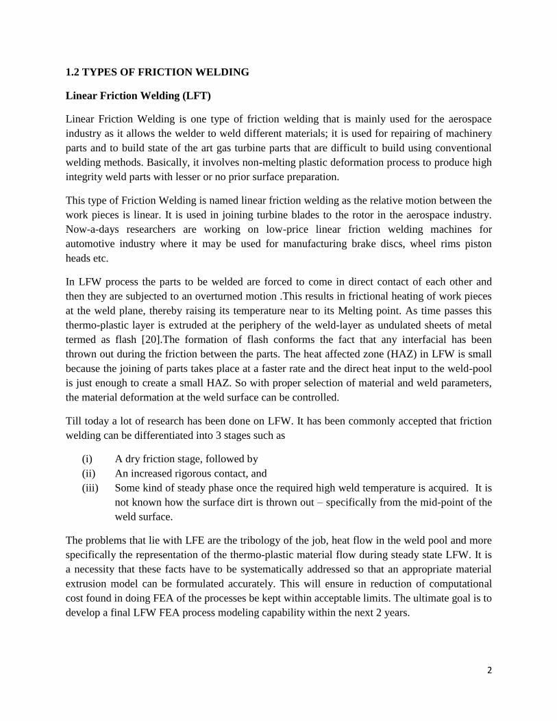
Rotary Friction Welding (RFW)
In RFW, one work piece is rotated against the other.it is the most commonly used friction
welding process in automobile industry. The process has been used to manufacture suspension
rods, steering columns, gear box forks and drive shafts and engine valves, in which there is
requirement of welding of unalike materials of valve stem and head.
Fig 1 RFW Process
4
Inertia Friction Welding
In this friction welding, the energy required to make the weld is harnessed from the rotational
KE stored in a fly wheel of the welding set up.
In Inertia Friction Welding, one part is connected to a flywheel and the other is constrained from
rotating. The flywheel is accelerated to a specific rotational speed to store the required energy.
Then the driving motor is withdrawn and the work pieces are forced together to interact directly.
This drives the surfaces to rub against each other under pressure. The kinetic energy stored in the
rotating flywheel forces the part attached to t to rotate and this rotation is opposed by the other
constrained part which results in generation of heat. Due to the opposition by the constrained
work piece the fly wheel get slowed down and its KE gets converted into heat. An increment
axial force is applied before rotation stops. The axial force is kept for a specific time even after
rotation stops.
Friction Stud Welding
It was developed by the USA Navy in 1998 and was first commercially performed at a depth of
1300 feet and involved the friction welding of anode continuity tails to riser base piles using a
work-class ROV. The instrument used for the welding process was a Circle Technologies HMS
3000, which is hydraulically-driven, electronically-controlled, and rated to a depth of 3,000 feet
(910m). Based on this concept, the Naval Sea Systems Command (NAVSEA) initiated another
program to evaluate underwater friction stud welding for use in submarine rescue. The program
required interfacing the HMS 3000 friction stud welder with the Navy's atmospheric diving suit
(ADS), rated to 2,000 feet (606m). The feasibleness of this idea was demoed in 2001 by
Oceaneering International using their WASP ADS and the HMS 3000 friction stud welding
system. Friction stud welding can be used to weld a pattern of studs to the hull of a broken
submarine, to which a pad- eye can be attached for the SRC haul-down cable and life bearing gas
can be supplied by means of a hot tap method using hollow studs. Combined with an AD, the
system allows rescue capabilities well beyond 300 feet (91m).
Oceaneering developed the application for commercial offshore submarine repairs at the same
time when Navy tried to use the method to for underwater friction stud welding for rescue
missions in case of underwater accidents in sea. But there was a little public information on the
mechanical properties of underwater friction stud welding. The usability of this process for any
offshore repairing without a complete knowledge of mechanical, corrosion, and fatigue would
not be acceptable.
5
Friction Stir Welding
Friction Stir Welding (FSW) is a recently developed friction welding process which was
developed at The Welding Institute (TWI), Cambridge, UK [19].This method uses a rotating
non-consumable welding tool
This technique uses a non- consumable rotating tool to create frictional heat and distortion at the
welding position, thereby upsetting the development of a joint, while the material is in the solid
state. The main benefits of FSW, being a solid-state procedure, are low alteration, absenteeism of
melt-related flaws and great joint strong point, even in those alloys that are considered non-
joinable by conventional practices (e.g., 5xxx and 6xxx series aluminum alloys). In addition,
friction stir welded joints are regarded as the absence of filler-induced glitches or defects, since
the method necessitates no filler. Also the hydrogen damage that occurs during welding of steel
and other iron alloys has to be avoided by decreasing the hydrogen contents of the friction stir
welded joints.
FSW has been effectively castoff to weld alike and unlike cast and wrought aluminum (Al)
alloys, steels, along with titanium (W), copper (Cu) and magnesium (Mg) alloys, different metal
cluster alloys and metal matrix amalgams. The skill can be used to crop butt, corner, lap, T, spot,
fillet and hem links also to weld deep objects, for example tanks and tube and parts with 3-D
outlines. In addition to producing joints, this process is besides appropriate for patch-up of
present joint. The primary industrialized and research interests, nevertheless, are being focused
on butt welding of aluminum alloy sheets and plate up to 7.62 cm thick. FSW can be done in all
points (horizontal, vertical, above and detour).
Replacement of secured joints with friction stir welded linkages can clue to substantial weight
and cost stashes, striking plans for many engineering farms, together with the transport industry
overall and the airframe industry in precise. The removal of the fasteners reduces the weight of
FSW. The cost savings could be realized by a sophisticated design, engineering, gathering and
upkeep times, carried out by the possible lessening in part amount. FSW joints can be used to
replace fastened joints which would result in removal of strain concentration effects related with
fastener pigpens, recover corrosion enactment by eradicating the clips by means of a source of
contradictory metal contact and in the incident of butt linkages, by abolishing joint boundaries
and the associated cracks and other sorts of corrosion.
Many leading Industries involving in manufacturing aluminum parts are aerospace industries
such as NASA, Boeing, Eclipse, Airbus, BEA, Lockheed Martin etc. , US Navy, automotive
industries such as Kawasaki, Mitsubishi ,Lamborghini, Audi etc.
6
Some of the advantages of friction stir welding are
1. It is an energy efficient Welding process
2. It uses non-consumable tool to perform welding
3. It generates anticipated microstructures in the weld and HAZ
4. Conventionally impossible material combinations can be welded by FSW
5. It results in lesser distortion due to smaller HAZ
6. It is environment friendly as there is no formation of hazardous gas, noise or flame
1.3 PRINCIPLE OF FRICTION WELDING
Friction welding is carried out by translating or rotating one component comparative to another
along a mutual boundary, whereas smearing a compressive force through the joint. The frictional
heat gets spawned at the boundary softens both components and when they got altered the border
material gets extruded out of the ends of the combined so that fresh material from each module is
gone along the new interface. The relative cue is then stopped, and a advanced closing
compressive power is applied earlier to the joint is permitted to cool. The main aspect of friction
welding is that no liquefied solid is generated as the weld gets created in the solid state itself.
The principle of this method is the changing of kinetic energy (it may be rotational or
translational) energy into heat energy through friction. One piece is obsessed and revolved about
its axis while the other part to be joined to it is engrossed and is not revolved but can be relocated
axially to create interaction with the spinning component. When fusion temperature is reached,
then gyration is clogged and forging pressure is smeared. Heat is produced due to friction and is
focused and contained at the edge, grain structure is polished by scorching exertion. Then the
joint gets formed but there is no melting of material.
Momentarily in the friction-welding process the parts to be welded are brought into contact
whereas one of them is stationary and the other is revolved swiftly about its own axis. Once the
heat spawned by rubbing at the boundary is abundant for solid phase welding deprived of
melting, the turning is clogged and the components are enforced together under stress fabricating
confined forging which achieves the close joining and likewise banishes all surface impurity and
some of the distressed solid called flash at the joint.
In friction welding one part is swapped and other is seized motionless. The chunk that is
revolved is taken into connection with the motionless component and when ample heat is
generated to bring the components to a plastic phase and the desired burn-off is achieved,
rotation is clogged. More axial stress is then smeared among the two modules resulting in a solid
7
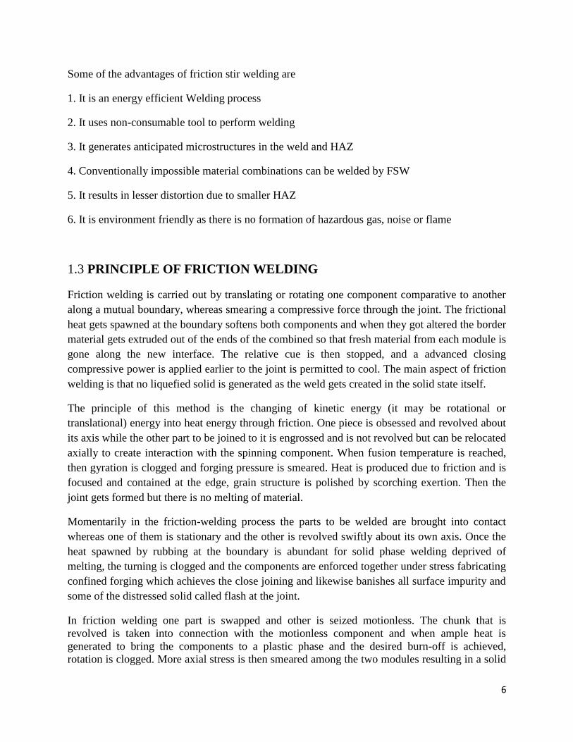
state connection at the border creating a friction welded joint. Fig.2 shows that the One piece
rotated quickly, the other is immobile, Revolving and immobile constituents took together into
interaction and load is applied, Axial load is amplified to fetch components into a plastic state at
boundary, Rotation is clogged and more load is applied, As a result a full cross sectional weld in
the parent solid.
Fig 2 Different stages of FRW
8
1.4 ADVANTAGES
Friction welding is cost-effective since it badges joining together dissimilar materials, one of
them may be cheap and its quality controller cost may be minimal with an assurance of high
strength welds. Furthermore, the weld cycle is very short, so that output is very eye-catching.
Friction welding process may fit for mass manufacture.
The friction welding route is right for non-homogeneous joints linking things having quite
altered mechanical, chemical and thermal properties. The procedure is appropriate for
automation and adoptable for robotic application. Other advantages are:
- Material and machining charge savings is more
-Full cross section gets bounded perfectly
- High manufacture rates
-Weld heat affected zone (HAZ) has a reasonable grain hot-worked construction, there is no cast
structure found with conventional welding
-The resulting material gets stronger than the parent material ex:-FSW Al and Cu joint has more
strength than both Al and Cu
-Like and unlike materials can be welded with no extra fluxes or filler metals
-Superb mechanical properties are proven by fatigue, tensile, bend experiments
-no hazardous gas is produced
-no sponginess
-no scatter
-No need of recruiting certified welders for performing FSW
-It can be performed in all loci
-It is more energy effective than other welding skills
-it is an environment friendly process as it generates no fumes, gasses or leftover crick
-FSW joint strong point is similar or even greater than that of parent material
-It can weld cheap, less heavy or cylindrical material to expensive material.
9
1.5 Disadvantages
Friction welding has some disadvantages such as friction welding of all structure is not
practicable, a machine of adequate power is required and short run of the welding process may
not be economical.
Other disadvantages are cost of instruments required which must be right for the proposed joins,
the cost of the tools to be used and the set up cost. These costs per weld may become very high
for welding dissimilar materials such as Titanium, Magnesium etc. Close-fitting among parts and
maintaining close concentricity that are required for FSW may become difficult in some cases.
Likewise there may be rise in total cost when finishing procedures are required.
1.6 Applications of FRW
As time passes friction welding has found many applications in Commercial, Aerospace,
Hydraulic, Automotive industries etc.
1. Commercial
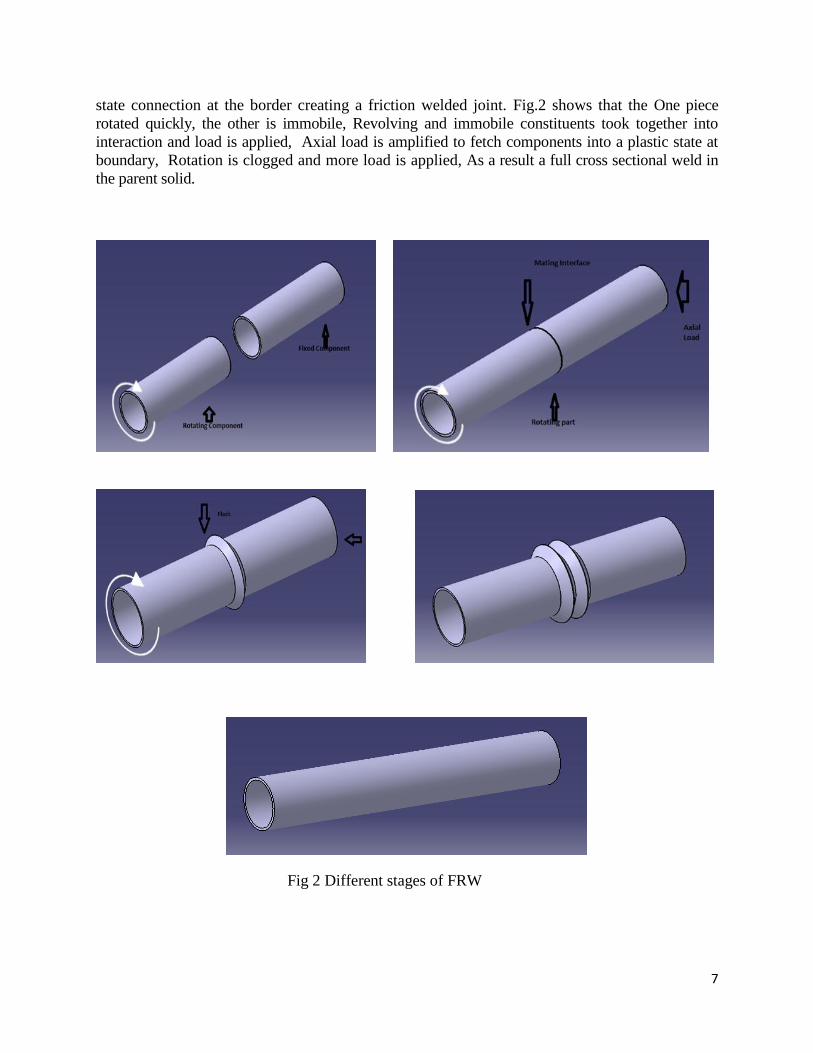
Inertia Friction Welding is mainly used for commercial purpose because the weld is skillful
rapidly and with smallest clean-up. Since the weld has high strength, it delivers a solider quantity
than customary welds. Tool additions, tool spaces, baseball bats, air cylinders, ammunitions,
fasteners, oil cylinders and water tube fittings, bicycle parts, medical equipment, marine
equipment, electrical tools, photographic and sound apparatus are made using inertia friction
welding.
Fig 3 Axle of a Bi-cycle
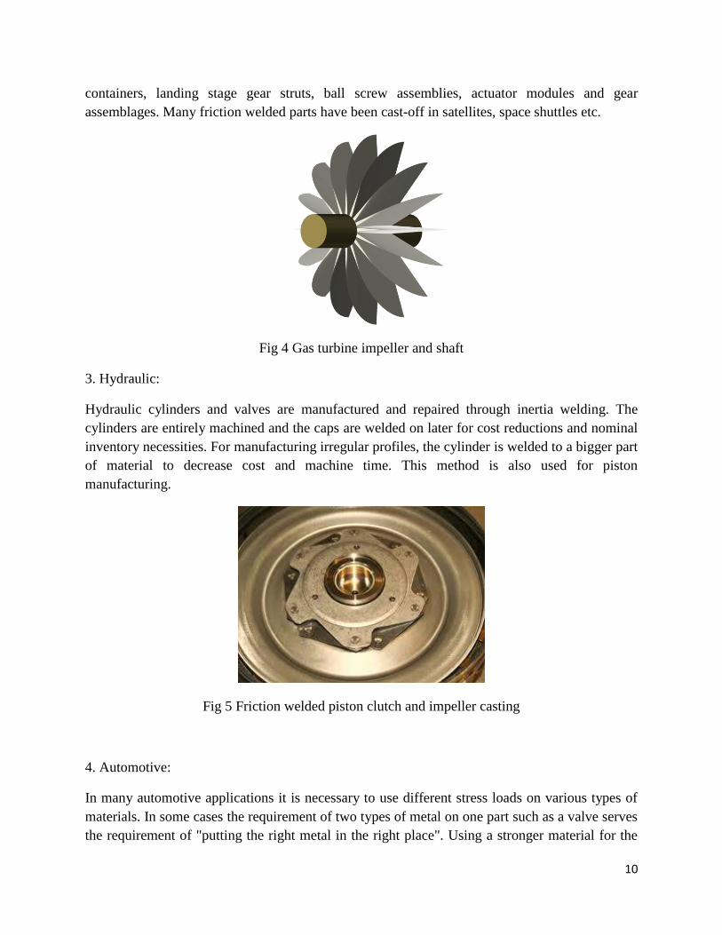
2. Aerospace
Inertia Friction welding and friction stir welding are mainly used in aerospace industry. These
are used to manufacture aero-plane parts such as gas turbine wheels and shafts, pressure
10
containers, landing stage gear struts, ball screw assemblies, actuator modules and gear
assemblages. Many friction welded parts have been cast-off in satellites, space shuttles etc.
Fig 4 Gas turbine impeller and shaft
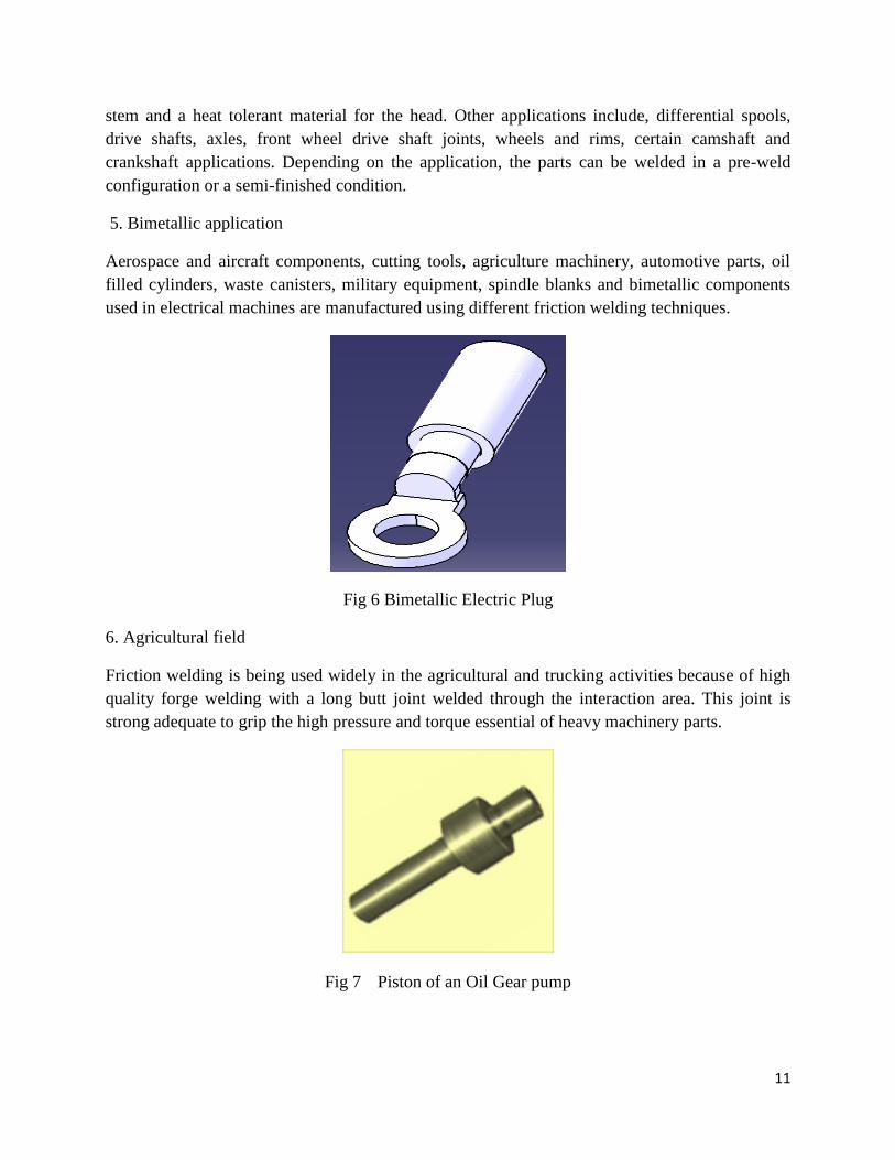
3. Hydraulic:
Hydraulic cylinders and valves are manufactured and repaired through inertia welding. The
cylinders are entirely machined and the caps are welded on later for cost reductions and nominal
inventory necessities. For manufacturing irregular profiles, the cylinder is welded to a bigger part
of material to decrease cost and machine time. This method is also used for piston
manufacturing.
Fig 5 Friction welded piston clutch and impeller casting
4. Automotive:
In many automotive applications it is necessary to use different stress loads on various types of
materials. In some cases the requirement of two types of metal on one part such as a valve serves
the requirement of "putting the right metal in the right place". Using a stronger material for the
11
stem and a heat tolerant material for the head. Other applications include, differential spools,
drive shafts, axles, front wheel drive shaft joints, wheels and rims, certain camshaft and
crankshaft applications. Depending on the application, the parts can be welded in a pre-weld
configuration or a semi-finished condition.
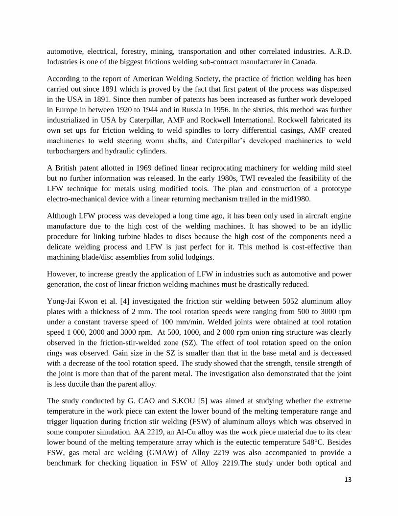
5. Bimetallic application
Aerospace and aircraft components, cutting tools, agriculture machinery, automotive parts, oil
filled cylinders, waste canisters, military equipment, spindle blanks and bimetallic components
used in electrical machines are manufactured using different friction welding techniques.
Fig 6 Bimetallic Electric Plug
6. Agricultural field
Friction welding is being used widely in the agricultural and trucking activities because of high
quality forge welding with a long butt joint welded through the interaction area. This joint is
strong adequate to grip the high pressure and torque essential of heavy machinery parts.
Fig 7 Piston of an Oil Gear pump
12
Chapter 2
LITERATURE REVIEW
2.1 LITERATURE REVIEW
It is a fact that the essential force to originate sliding a material is better than that to continue
motion so the coefficient of static friction becomes greater than coefficient of dynamic friction. It
is detected that the choice of standards of frictional forces varies by orders of scale dependent on
the span of the tenders, macroscopic or microscopic.
French physicist Guillaume Amonton stated in his empirical law of sliding friction, the friction
force is proportionate to the normal weight.
Mathematically,
Friction force = coefficient of friction X normal weight
Generally the specific value of the coefficient of friction rests intensely on the laboratory
conditions under which it is sedated. In addition to this second rule of friction demonstrates that
friction force is self-governing of the seeming area of contact between the two planes. Charles
Augustin de Coulomb has stated in his third law of macroscopic friction, that friction force is
self-regulating of sliding velocity. The coefficient of dynamic friction is estimated to be nearly
free from ordinary slithering velocities comparable performance is shown for temperature
changes, unless phase transformations look like at the interface.
Early attempts of Amonton and Coulomb among others expected that mechanical linking among
rigid or elastically deforming astringencies can be accountable for the frictional force and the
resulting mechanical wear and heat generation. This model adopts two bodies that perform both
longitudinal and transverse gesture at the equivalent time; work is done by normal load after the
upper form has reverted to its lowest location and the potential energy is fully recovered. But the
major drawback is that macroscopic observations may not agree with this philosophy as
extremely polished and even surfaces are needed for cold welding and it may not show low
friction. Another problem with this postulate is that the adsorbed films change friction by
instructions of scale whereas upholding similar roughness of the surface.
A.R.D. Industries manufactures friction welded parts and has performed sub-contract friction
welding of costumer goods for a large number of companies that include agricultural,
13
automotive, electrical, forestry, mining, transportation and other correlated industries. A.R.D.
Industries is one of the biggest frictions welding sub-contract manufacturer in Canada.
According to the report of American Welding Society, the practice of friction welding has been
carried out since 1891 which is proved by the fact that first patent of the process was dispensed
in the USA in 1891. Since then number of patents has been increased as further work developed
in Europe in between 1920 to 1944 and in Russia in 1956. In the sixties, this method was further
industrialized in USA by Caterpillar, AMF and Rockwell International. Rockwell fabricated its
own set ups for friction welding to weld spindles to lorry differential casings, AMF created
machineries to weld steering worm shafts, and Caterpillar’s developed machineries to weld
turbochargers and hydraulic cylinders.
A British patent allotted in 1969 defined linear reciprocating machinery for welding mild steel
but no further information was released. In the early 1980s, TWI revealed the feasibility of the
LFW technique for metals using modified tools. The plan and construction of a prototype
electro-mechanical device with a linear returning mechanism trailed in the mid1980.
Although LFW process was developed a long time ago, it has been only used in aircraft engine
manufacture due to the high cost of the welding machines. It has showed to be an idyllic
procedure for linking turbine blades to discs because the high cost of the components need a
delicate welding process and LFW is just perfect for it. This method is cost-effective than
machining blade/disc assemblies from solid lodgings.
However, to increase greatly the application of LFW in industries such as automotive and power
generation, the cost of linear friction welding machines must be drastically reduced.
Yong-Jai Kwon et al. [4] investigated the friction stir welding between 5052 aluminum alloy
plates with a thickness of 2 mm. The tool rotation speeds were ranging from 500 to 3000 rpm
under a constant traverse speed of 100 mm/min. Welded joints were obtained at tool rotation
speed 1 000, 2000 and 3000 rpm. At 500, 1000, and 2 000 rpm onion ring structure was clearly
observed in the friction-stir-welded zone (SZ). The effect of tool rotation speed on the onion
rings was observed. Gain size in the SZ is smaller than that in the base metal and is decreased
with a decrease of the tool rotation speed. The study showed that the strength, tensile strength of
the joint is more than that of the parent metal. The investigation also demonstrated that the joint
is less ductile than the parent alloy.
The study conducted by G. CAO and S.KOU [5] was aimed at studying whether the extreme
temperature in the work piece can extent the lower bound of the melting temperature range and
trigger liquation during friction stir welding (FSW) of aluminum alloys which was observed in
some computer simulation. AA 2219, an Al-Cu alloy was the work piece material due to its clear
lower bound of the melting temperature array which is the eutectic temperature 548°C. Besides
FSW, gas metal arc welding (GMAW) of Alloy 2219 was also accompanied to provide a
benchmark for checking liquation in FSW of Alloy 2219.The study under both optical and
14
scanning electron microscopy revealed found that in GMAW of Alloy 2219, q (Al2Cu) particles
performed as in-situ micro sensors, which indicates liquation due to reaction between CU and Al
forming eutectic particles upon reaching the eutectic temperature. But in FSW, no evidence of q-
induced liquation was found suggesting that the eutectic temperature was not reached.
J. Adamowski et al. [6] analyzed the mechanical properties and microstructural variations in
Friction Stir Welds in the AA 6082-T6 with varying process parameters. Tensile test of the welds
was done and relation among the process parameter was judged. Microstructure of the weld
interface was observed under optical microscope. Also micro hardness of the resulting joint was
measured. It was observed that test welds show resistance to increment of welding speed,
Hardness reduction was observed in weld nugget and heat affected zone (HAZ). The reason for
this occurrence was the kinetic and thermal asymmetry of the FSW process. An initial stage of a
longitudinal, volumetric defect was found at the interface of weld nugget and TMAZ. The
hardness was inferior to that of fusion welding. Tunnel (worm hole) defects were found in the
nugget zone.
H.J.LIU et al. [7] studied the characteristics of friction welding characteristics of AA 2017-T351
sheet in which they found that the relation between the parameters and also they have studied the
microstructure of the weld joints. Graphs between revolutionary pitch and strength, distance
from weld center and Vickers Hardness, revolutionary pitch and fracture location at the joints
were plotted. From the hardness test and tension tests it was deducted that FSW makes the
material soft and it also decreases the tensile strength of the material. Microscopic analysis
confirms the generations of fractures in the joint at the interface among weld nugget and
thermodynamically affected zone.
M.Vural et al. [8] scrutinized the friction stir welding competency of the EN AW 2024-0 and EN
AW 5754-H22 Al alloys. These two Aluminium alloys are extensively used in the industry. The
experiment presented that the hardness value of EN AW 2024-0 at the weld area is increased
about 10-40 Hv. This may be the result of recrystallization and compact grain structure
formation. But hardness of EN AW 5754-H22 got decreased due recrystallization and loose grain
structure formation. Welding performance of EN AW 2024-0 is 96.6 and for EN AW 5754-H22
it is 57%. Welding performance of dissimilar Aluminium alloys EN AW 2024-0 and EN AW
5754-H22 is reached a value of 66.39%. Analysis of Welding zone using scanning electron
microscope showed no change in the microstructure in the welding zone. Hardness distribution at
the weld zones didn’t show any significant change in hardness.
R. Nandan et al. [3] reviewed the recent trends in FSW process, weldment structure and
properties of the resulting material at the weld joints. This study dealt with the essential
understanding of the process and its consequences in the molecular level. Other characteristics
that are studied are heat generation, heat transfer and plastic flow during welding, components of
tool design, study of defect formations and the structure and properties of the welded materials.
They described important factors that have to be optimized to reduce fracture and improve the
15
uniformity of weld properties so that FSW can be expanded to new engineering fields. Principles
of heat transfer, material flow, tool-work–piece contact conditions and properties of various
process parameters, efficient tools have been formulated. Uncertain parameters of FSW like
friction coefficient, the extent of slide between the tool and the work–piece, the heat transfer
coefficients for different work–piece surfaces, splitting of the heat amongst the work–piece and
the tool at the tool-work piece boundary are also counted for and processes to optimize these
parameters are discussed.
The weld ability of AA 5083-H111 (non-heat treatable) and AA 6082-T6 (heat treatable)
Aluminium alloys, that are extensively used in welding production is inspected by
D.M.Rodrigues et al. [9] The work pieces were welded under broad range of FSW parameters
(changing tool dimensions, rotation and traverse velocities, axial force and incline angles) to
ensure high welding speeds. The welds defects and weld strength were analyzed and compared
to the distinctly different plastic behaviors of both base materials. The study proved that high
traverse speed can be achieved with proper tool parameters, base material characteristics and
plate thickness. It was shown that founding suitable axial force values rests intensely on base
material characteristics. It was determined that the mechanical properties of the non-defective
welds are relatively independent of the welding conditions. For AA 6082 alloy, the use of very
high welding speeds ascertained to be very operative in evading extra softening in the HAZ, with
positive values in weld yield strength productivity.
S Yazdanian et al. [10] scrutinized the effect of pin length, welding speed and rotation rate on the
weld strength using AA 6060 as work piece for FSW. The major factor in determining the weld
strength is the rotation speed of the tool. Higher rotation rate made the joint weak and vice versa.
Effect of rotation speed on heat generation and material flow was also enlightened. It was found
that higher rotation rate may result in larger interface lifting and hence higher degree of hooking,
reducing the effective weight bearing area.
Mohamed Merzoug et al. [11] described the main parameters of Friction stir spot welding
(FSSW). The parameter under consideration is shape of the tool. It is established that shape of
tool decides the resistance of the joint of welding. This may be due to the heat gradients and
mechanical stresses experienced by material throughout welding. The nature of material and the
selection of the parameters (geometry, positioning, tool rotating, penetration depth and the force
applied of the pin and the shoulder) also decide the heat generation and the strength of the weld
joint.
The effect of process constraints (cycle time, tool speed and axial force) on the sample
temperature that is measured 2 mm away from the weld in spot friction welding (SFW) of Al
6111-T4 was investigated by S.G.Arul et al. [12] They tried to correlate temperature with shear
load. It was found that the maximum lap shear load should be greater than 2.5 kN and
temperatures should be larger than a threshold value (350 Centigrade at a location close to the
SFW joint in the experiment) to achieve decent joint strength. During microstructure analysis
16
two internal welds geometric structures at the cross section area were identified which were may
be due to the shear and mixed failure modes of the lap shear tested samples. A model was settled
and corroborated using experimental data of the cross section area of SFW joint with either shear
or mixed mode fracture that forecasted that SFW joint strength is maximized at the transition
region between the shear and mixed mode fracture.
Friction stir welding of different materials was done by D.Muruganandam et al. [13] for four
different tool rotation speeds namely 600, 800, 1000 and1200 rpm. Radiology was done to study
the defects in the weld joint. The analysis indicated that defect concentration was maximum for
the 600 rpm tool rotation. It was a little reduced for 800 rpm and even lesser for the 1000 rpm
speed rotation. Least defects were found at the highest rpm (1200).
Friction welding of austenitic stainless steel (AISI 304) and optimization of the welding
parameters to establish weld quality was done by P.Sathiya et al. [14] Austenitic stainless
specimens were welded using the laboratory model friction welding machine. Aural emission
originated during the tension test from the joints was acquired to evaluate the quality of the
joints. They also proposed a genetic algorithm to decide near optimal configurations of process
parameters. The tensile tests showed that the weld joints exhibited similar strength with the base
material. The post welding analysis showed increase in hardness due to recrystallization. Micro
vicker’s hardness increases with increasing friction time may be due to the heating of material at
the weld region. The objective function is formulated by regression analysis. Genetic Algorithm
is then applied to the objective function for optimizing the process parameters. The minimum
difference observed between theoretical and the experimental values confirm the applicability of
GA for the friction welding process.
Rotary friction welding of AA1050 aluminum and AISI 304 stainless steel was performed and
tensile tests, Vickers microhardness, metallographic tests and SEM-EDX analysis etc. were
conducted to assess the effect of weld parameters on microscopic as well as physical properties
of the weld joint by Eder Paduan Alves et al.[15] Joints were acquired with greater mechanical
properties of the AA1050 aluminum, with fracture arising in the aluminum away from the
bonding boundary. The inspection by EDX at the interface of the junction presented that inter-
diffusion occurs between the main chemical components of the materials involved.
S.Senthil Kumaran et al. [16] carried out friction welding of tube to tube plate using an external
tool and optimized the process parameters by Taguchi L8 orthogonal array. The arrangement of
the process parameters was obtained and ANOVA had been accompanied to predict the
statistical importance of the process parameters. They implemented Genetic Algorithm (GA) to
optimize the parameters. The real-world viability of applying GA to friction welding process was
ensured by studying the eccentricity between forecasted and experimentally acquired friction
welding process parameters
17
Chapter 3
EXPERIMENTAL WORK
3.1 Introduction
In this investigation of friction stir welding, Aluminium pipe and stainless steel plate is fixed to a
fixture designed for the experiment and the fixture in turn is held with the help of chuck of a
center lathe and the tool is attached to the tail stuck of the lathe through a drill chalk.
3.2 Materials Selection
3.2.1 Fixture
1. GI pipe of Outer diameter 60mm and inner diameter 53 mm
2. Mild steel plate of diameter 100mm and thickness 3mm
3. 3 nut and bolt pair
3.2.2 Tool
1. C-45 carbon steel
3.2.3. Work piece
The work piece materials are Aluminium pipes and stainless steel plates
1. Aluminium pipes of diameter
a. 18.5 mm(4 piece)
b. 25 mm(2 piece)
c. 31 mm(1 piece)
2. Stainless Steel plate of shape
a. 80 mm×30 mm(6 piece)
b. 80 mm×45 mm(1 piece)
3.2.4 Back-up plate
1. 5 plates of size 80mm×45mm
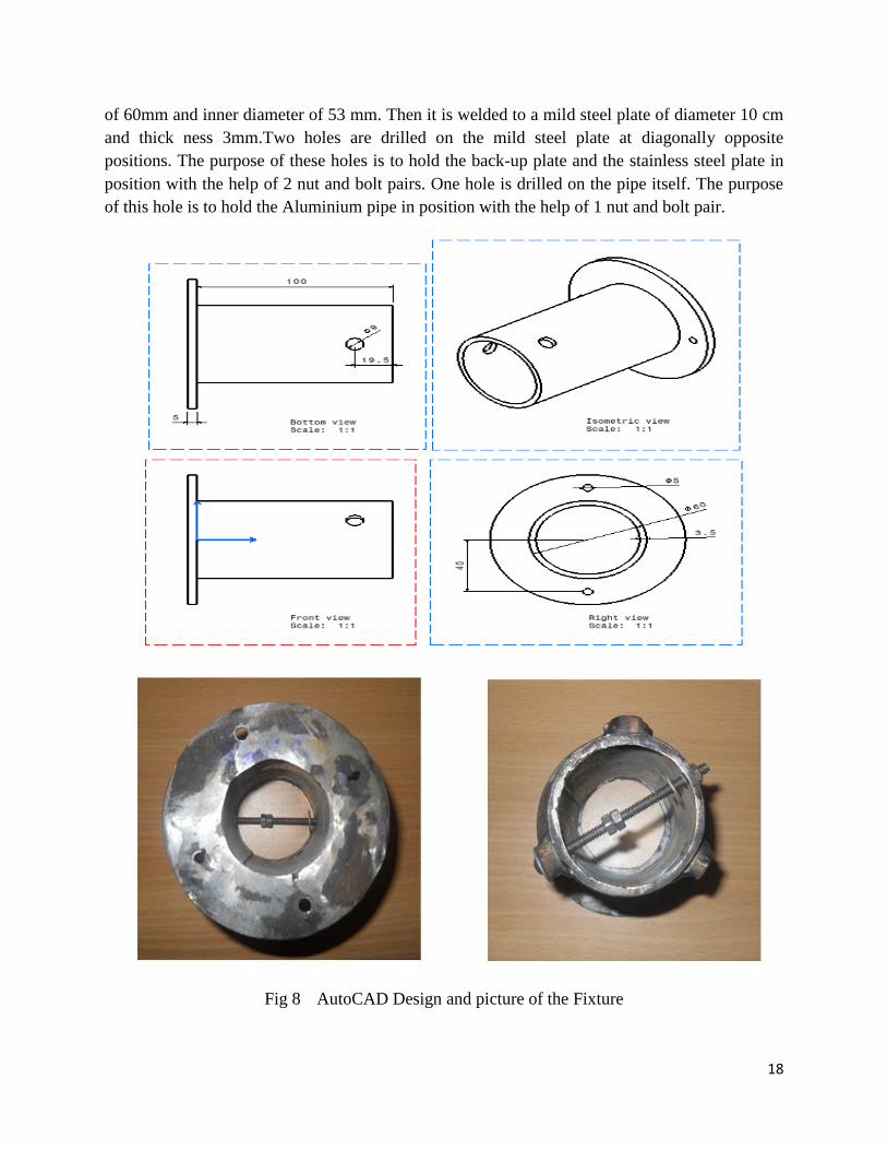
3.3 Fixture design
The fixture is designed for performing the experiment on center lathe machine. The operations
involved are cutting the galvanized steel pipe into a size of 10 cm. The pipe has a outer diameter
18
of 60mm and inner diameter of 53 mm. Then it is welded to a mild steel plate of diameter 10 cm
and thick ness 3mm.Two holes are drilled on the mild steel plate at diagonally opposite
positions. The purpose of these holes is to hold the back-up plate and the stainless steel plate in
position with the help of 2 nut and bolt pairs. One hole is drilled on the pipe itself. The purpose
of this hole is to hold the Aluminium pipe in position with the help of 1 nut and bolt pair.
Fig 8 AutoCAD Design and picture of the Fixture
19
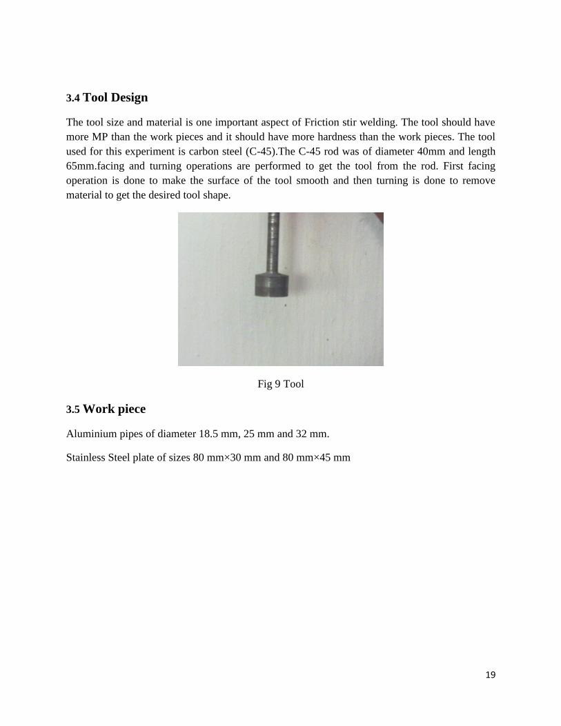
3.4 Tool Design
The tool size and material is one important aspect of Friction stir welding. The tool should have
more MP than the work pieces and it should have more hardness than the work pieces. The tool
used for this experiment is carbon steel (C-45).The C-45 rod was of diameter 40mm and length
65mm.facing and turning operations are performed to get the tool from the rod. First facing
operation is done to make the surface of the tool smooth and then turning is done to remove
material to get the desired tool shape.
Fig 9 Tool
3.5 Work piece
Aluminium pipes of diameter 18.5 mm, 25 mm and 32 mm.
Stainless Steel plate of sizes 80 mm×30 mm and 80 mm×45 mm
20
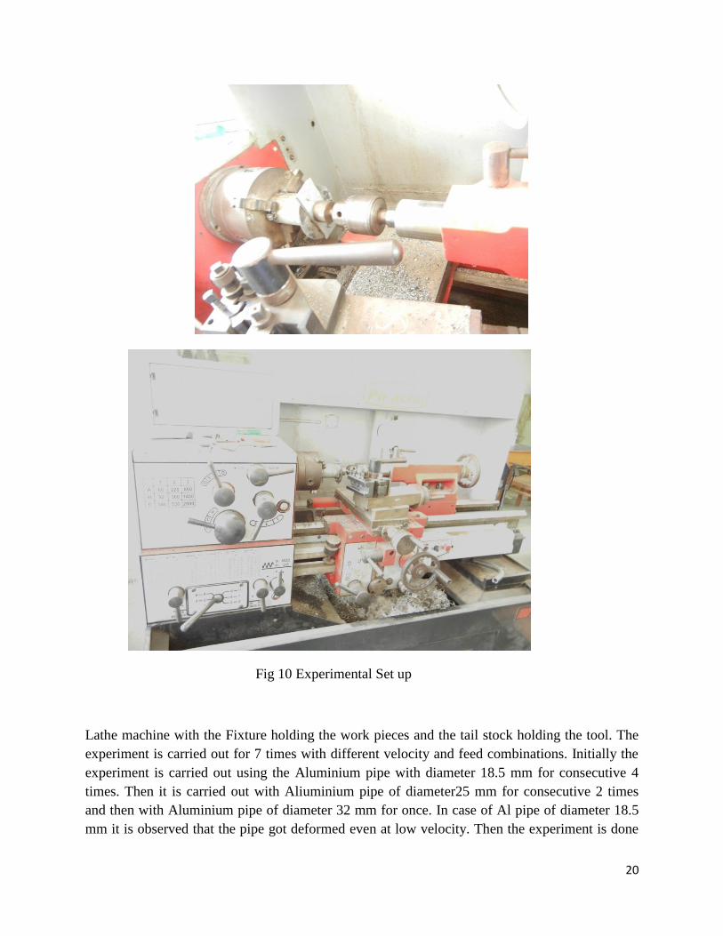
Fig 10 Experimental Set up
Lathe machine with the Fixture holding the work pieces and the tail stock holding the tool. The
experiment is carried out for 7 times with different velocity and feed combinations. Initially the
experiment is carried out using the Aluminium pipe with diameter 18.5 mm for consecutive 4
times. Then it is carried out with Aliuminium pipe of diameter25 mm for consecutive 2 times
and then with Aluminium pipe of diameter 32 mm for once. In case of Al pipe of diameter 18.5
mm it is observed that the pipe got deformed even at low velocity. Then the experiment is done

21
using back-up plate. The deformation after using the back-up plate is lesser but the welded joint
is not strong enough to hold the pipe and the stainless steel plate. Then the experiment is carried
out using Aluminium pipe of diameter 25 mm and stainless steel plate of size (80×35) mm with
back up plate. This shows some promises as the deformation in this case is smaller and the joint
appeared to be stronger. Then the experiment is carried out using Aluminium pipe of diameter 32
mm and stainless steel plate of dimension 80×45mm with back up plate. The experiment showed
that the deformation of the Aluminium pipe and stainless steel plate is more in this case.
22
Chapter 4
Result and Discussions
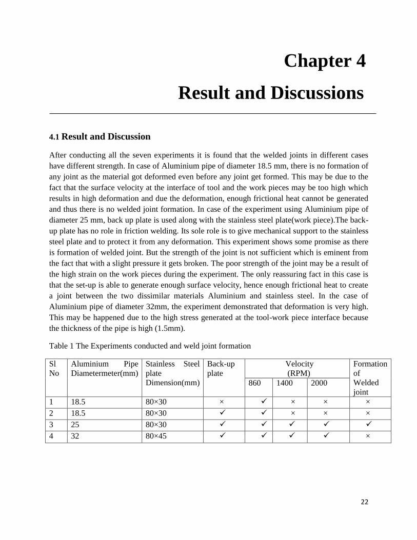
4.1 Result and Discussion
After conducting all the seven experiments it is found that the welded joints in different cases
have different strength. In case of Aluminium pipe of diameter 18.5 mm, there is no formation of
any joint as the material got deformed even before any joint get formed. This may be due to the
fact that the surface velocity at the interface of tool and the work pieces may be too high which
results in high deformation and due the deformation, enough frictional heat cannot be generated
and thus there is no welded joint formation. In case of the experiment using Aluminium pipe of
diameter 25 mm, back up plate is used along with the stainless steel plate(work piece).The back-
up plate has no role in friction welding. Its sole role is to give mechanical support to the stainless
steel plate and to protect it from any deformation. This experiment shows some promise as there
is formation of welded joint. But the strength of the joint is not sufficient which is eminent from
the fact that with a slight pressure it gets broken. The poor strength of the joint may be a result of
the high strain on the work pieces during the experiment. The only reassuring fact in this case is
that the set-up is able to generate enough surface velocity, hence enough frictional heat to create
a joint between the two dissimilar materials Aluminium and stainless steel. In the case of
Aluminium pipe of diameter 32mm, the experiment demonstrated that deformation is very high.
This may be happened due to the high stress generated at the tool-work piece interface because
the thickness of the pipe is high (1.5mm).
Table 1 The Experiments conducted and weld joint formation
Sl
No
Aluminium Pipe
Diametermeter(mm)
Stainless Steel
plate
Dimension(mm)
Back-up
plate
Velocity
(RPM)
Formation
of
Welded
joint 860 1400 2000
1 18.5 80×30 × × × ×
2 18.5 80×30 × × ×
3 25 80×30
4 32 80×45 ×
23
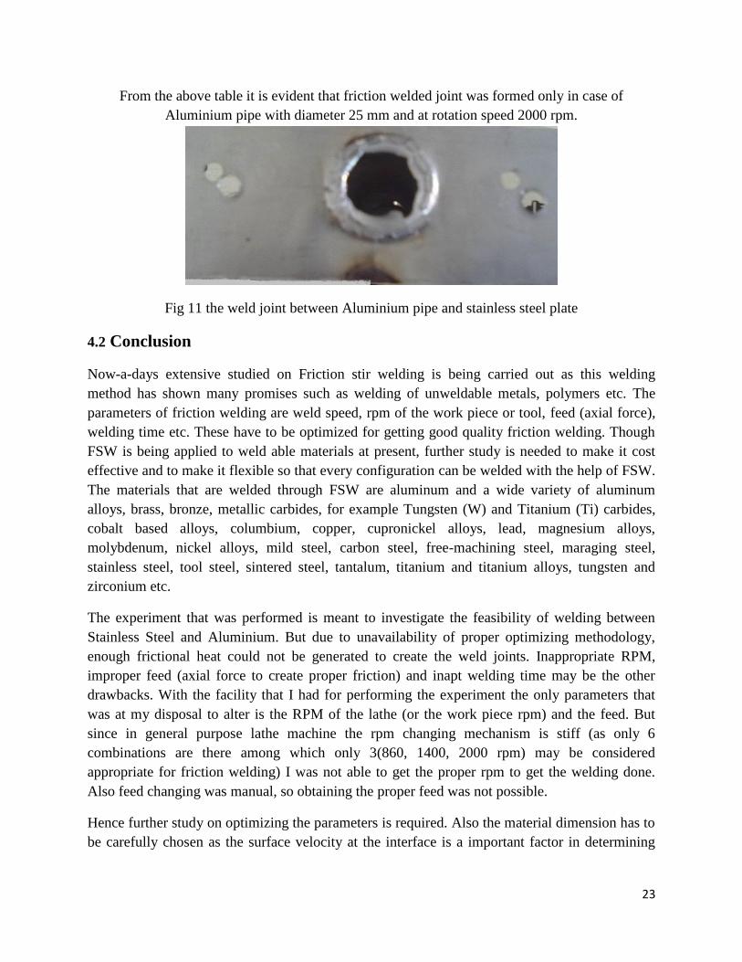
From the above table it is evident that friction welded joint was formed only in case of
Aluminium pipe with diameter 25 mm and at rotation speed 2000 rpm.
Fig 11 the weld joint between Aluminium pipe and stainless steel plate
4.2 Conclusion
Now-a-days extensive studied on Friction stir welding is being carried out as this welding
method has shown many promises such as welding of unweldable metals, polymers etc. The
parameters of friction welding are weld speed, rpm of the work piece or tool, feed (axial force),
welding time etc. These have to be optimized for getting good quality friction welding. Though
FSW is being applied to weld able materials at present, further study is needed to make it cost
effective and to make it flexible so that every configuration can be welded with the help of FSW.
The materials that are welded through FSW are aluminum and a wide variety of aluminum
alloys, brass, bronze, metallic carbides, for example Tungsten (W) and Titanium (Ti) carbides,
cobalt based alloys, columbium, copper, cupronickel alloys, lead, magnesium alloys,
molybdenum, nickel alloys, mild steel, carbon steel, free-machining steel, maraging steel,
stainless steel, tool steel, sintered steel, tantalum, titanium and titanium alloys, tungsten and
zirconium etc.
The experiment that was performed is meant to investigate the feasibility of welding between
Stainless Steel and Aluminium. But due to unavailability of proper optimizing methodology,
enough frictional heat could not be generated to create the weld joints. Inappropriate RPM,
improper feed (axial force to create proper friction) and inapt welding time may be the other
drawbacks. With the facility that I had for performing the experiment the only parameters that
was at my disposal to alter is the RPM of the lathe (or the work piece rpm) and the feed. But
since in general purpose lathe machine the rpm changing mechanism is stiff (as only 6
combinations are there among which only 3(860, 1400, 2000 rpm) may be considered
appropriate for friction welding) I was not able to get the proper rpm to get the welding done.
Also feed changing was manual, so obtaining the proper feed was not possible.
Hence further study on optimizing the parameters is required. Also the material dimension has to
be carefully chosen as the surface velocity at the interface is a important factor in determining

24
how much frictional heat will be generated at the interface and hence the feasibility of the
welding among the work pieces.
25
REFERENCE
1. Indira Rani M., Marpu R.N.
and A.C.S. Kumar , A Study of process parameters of friction stir
welded AA 6061 Aluminium alloy in O and T6 conditions, ARPN Journal of Engineering and
Applied Sciences, VOL. 6, NO. 2, FEBRUARY 2011.
2. Bussu G and Irving P E: ‘Static and fatigue performance of friction stir welded 2024-T351
Aluminium joints’. Proc 1st Int Symposium on Friction Stir Welding, Thousand Oaks, CA, 14-16
June 1999.
3. R. Nandan,T. DebRoy,H.K.D.H.Bhadeshia;Recent Advances in Friction Stir Welding –
Process, Weldment Structure and Properties, Progress in Materials Science 53 (2008) 980-1023.
4. Yong-Jai Kwon, Seong-Beom Shim, Dong-Hwan Park, Friction stir welding of 5052
aluminum alloy plates, Trans. Nonferrous Met. Soc. China 19(2009) s23−s27.
5. G.Cao, S.Kou, friction stir welding of 2219 aluminum: behavior of theta (Al2Cu) particles,
The Welding Journal, January 2005.
6. J. Adamowski , C. Gambaro, E. Lertora, M. Ponte, M. Szkodo, analysis of FSW welds made
of Aluminium alloy AW 6082-T6, Archives of Materials Science and Engineering, Volume
28,Issue 8,August 2007.
7. H. J. LIU, H. FUJII, K. NOGI, Friction stir welding characteristics of 2017-T351 aluminum
alloy sheet, JOURNAL OF MATERIALS SCIENCE 40 (2005) 3297 – 3299.
8. M. Vural, A. Ogur, G. Cam, C. Ozarpa, On the friction stir welding of Aluminium alloys EN
AW 2024-0 and EN AW 5754-H22, Archives of Materials Science and Engineering, Volume
28,Issue 1,January 2007.
9. D. M. Rodrigues, C. Leita˜o, R. Louro, H. Gouveia and A. Loureiro, High speed friction stir
welding of Aluminium alloys, Science and Technology of Welding and Joining, 2010.
10. S Yazdanian,Z W Chen, Effect of friction stir lap welding conditions on joint strength of
Aluminium alloy 6060,Processing,Microstructure and Performance of materials, IOP Conference
series: Material Science and Engineering 4(2009).
11. Mohamed Merzoug , Mohamed Mazari, Lahcene Berrahal, Abdellatif Imad, Parametric
studies of the process of friction spot stir welding of Aluminium 6060-T5 alloys, Materials and
Design 31 (2010) 3023–3028.
12. S. G. Arul, S. F. Miller, G. H. Kruger, T.-Y. Pan, P. K. Mallick and A. J. Shih. Experimental
study of joint performance in spot friction welding of 6111-T4 Aluminium alloy, Science and
Technology of Welding and Joining 2008 VOL 13 NO 7.
13. D.Muruganandam, K.S.Sreenivasan, S.Ravi Kumar, Sushilal Das, V.Seshagiri Rao, Study of
process parameters in friction stir welding of dissimilar Aluminium alloys, International
26
Conference on Industrial Engineering and Operations Management Kuala Lumpur, Malaysia,
January 22 – 24, 2011.
14. P. Sathiya, S. Aravindan and A. Noorul Haq, Friction welding of austenitic stainless steel
and optimization of weld quality, International Symposium of Research Students on Materials
Science and Engineering December, 2004.
15. Eder Paduan Alves, Francisco Piorino Neto, Chen Ying An, Welding of AA1050 aluminum
with AISI 304 stainless steel by rotary friction welding process, J. Aerosp.Technol. Manag., São
José dos Campos, Vol.2, No.3, pp. 301-306, Sep-Dec., 2010.
16. S. Senthil Kumaran, S. Muthukumaran, S. Vinodh, Optimization of friction welding of tube
to tube plate using an external tool, Struct Multidisc Optim (2010).
17. Dawes C J, Spurgin E J R and Staines D G: ‘Friction stir welding Aluminium alloy 5083 -
increased welding speed’. TWI Members Report 77354.1/98/991.2.
18.Ranjan Sahoo, Pinaki Samantaray, Study of friction welding, ethesis NIT Rourkela,2007.
19. Biallas G et al: ‘Mechanical properties and corrosion behaviour of friction stir welded 2024-T3’.
Proc 1st Int Symposium on Friction Stir Welding, Thousand Oaks, CA, 14-16 June 1999.
Related Documents