An Introduction To Historic Bridges Presented By: Nathan Holth Copyright © 2010-2015

Welcome message from author
This document is posted to help you gain knowledge. Please leave a comment to let me know what you think about it! Share it to your friends and learn new things together.
Transcript
An Introduction To Historic Bridges
Presented By: Nathan Holth Copyright © 2010-2015
An Introduction To Historic Bridges
1. Introducing Historic Bridges 2. Bridge Basics 3. Metal Truss Bridges and Iron and Steel Basics 4. Truss Bridge Configurations
8. Girder Bridges
6. Concrete Slab Bridges 5. Cantilever and Continuous Truss Bridges
7. Concrete Rigid-Frame Bridges
10. Stone Arch Bridges 11. Metal Arch Bridges
9. Concrete Arch Bridges

An Introduction To Historic Bridges
16. Movable Bridge Types 17. Historic Bridges: A Threatened Resource 18. Conclusions
13. T-Beam Bridges 14. Suspension Bridges 15. Pre-Stressed Concrete Bridges
12. Stringer Bridges
Part 1: Introducing Historic Bridges
An Introduction To Historic Bridges
What Is Historic?
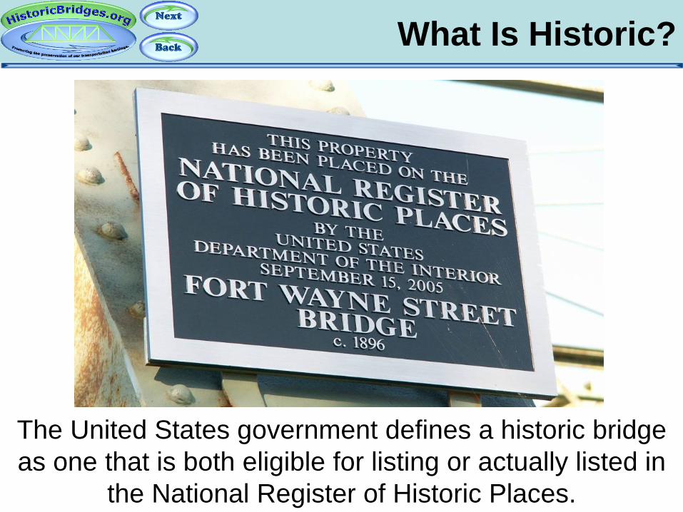
The United States government defines a historic bridge as one that is both eligible for listing or actually listed in
the National Register of Historic Places.
What Is Historic?
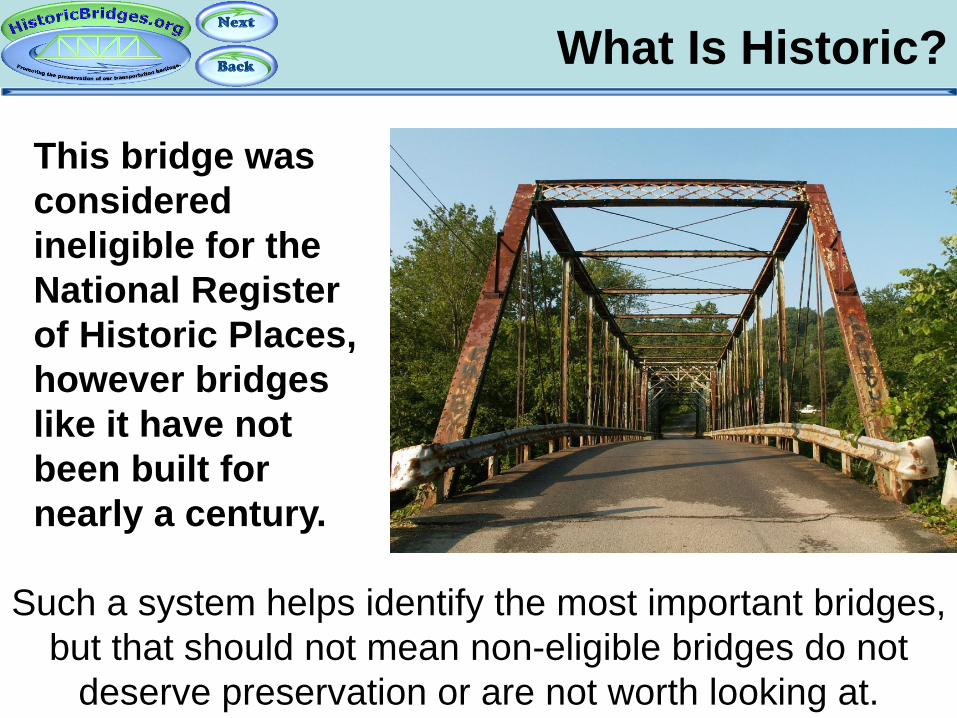
Such a system helps identify the most important bridges, but that should not mean non-eligible bridges do not
deserve preservation or are not worth looking at.
This bridge was considered ineligible for the National Register of Historic Places, however bridges like it have not been built for nearly a century.

What Is Historic?
Aside from the rare “National Historic Site” designation, the Canadian government has no specific country-wide program for designation of historic bridges, also called
“heritage bridges” and relies on provincial and municipal designations.
What Is Historic?
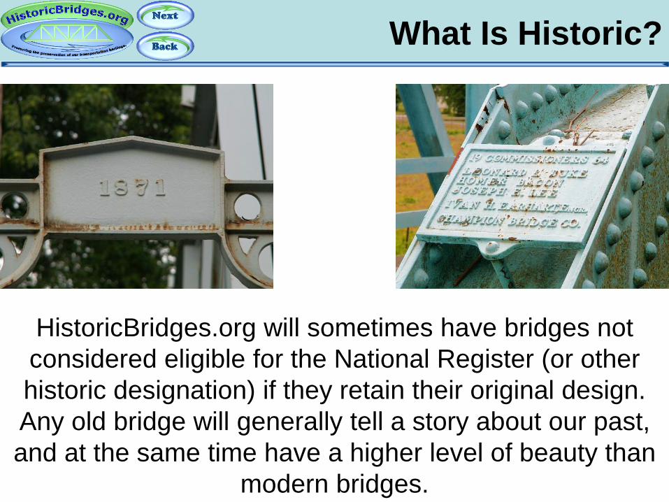
HistoricBridges.org will sometimes have bridges not considered eligible for the National Register (or other historic designation) if they retain their original design. Any old bridge will generally tell a story about our past, and at the same time have a higher level of beauty than
modern bridges.
What Is Historic?
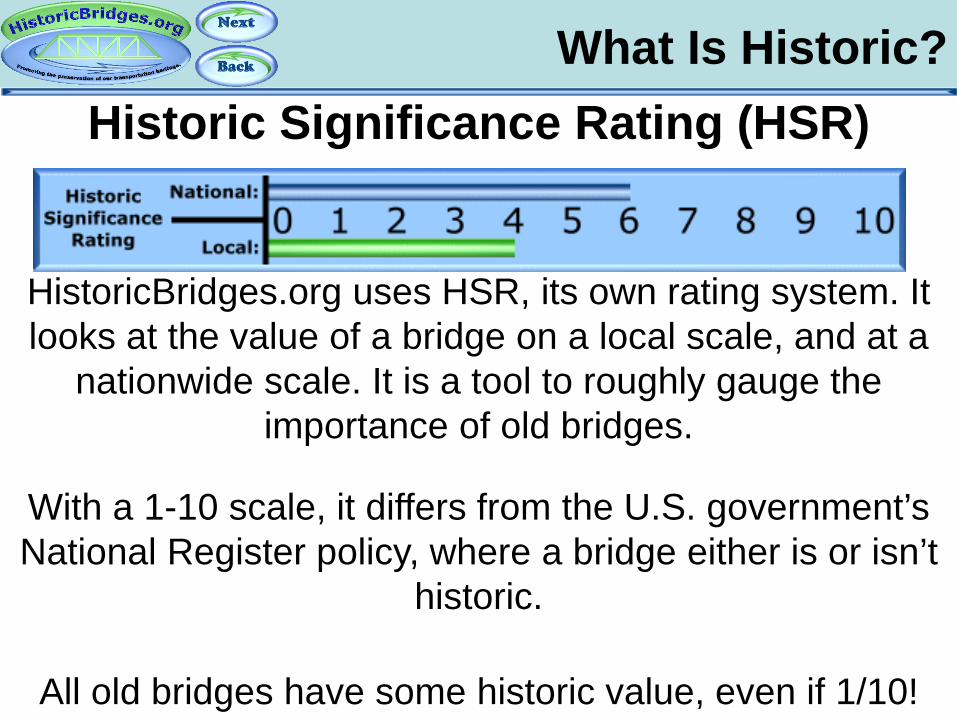
HistoricBridges.org uses HSR, its own rating system. It looks at the value of a bridge on a local scale, and at a
nationwide scale. It is a tool to roughly gauge the importance of old bridges.
Historic Significance Rating (HSR)
With a 1-10 scale, it differs from the U.S. government’s National Register policy, where a bridge either is or isn’t
historic.
All old bridges have some historic value, even if 1/10!
Evolution of Historic Bridges
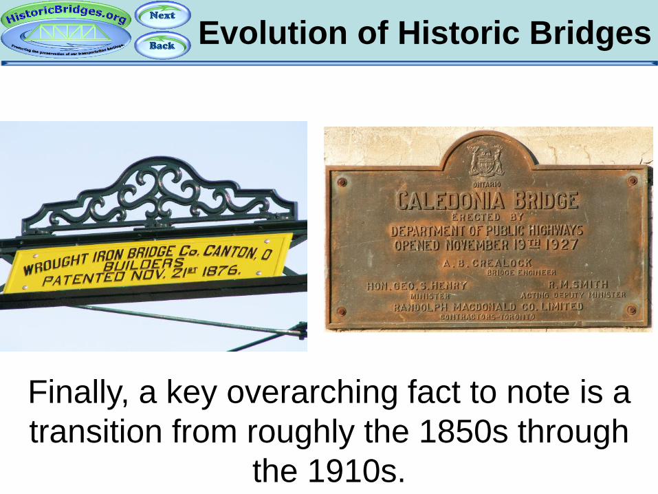
Finally, a key overarching fact to note is a transition from roughly the 1850s through
the 1910s.
Evolution of Historic Bridges
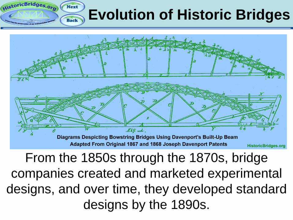
From the 1850s through the 1870s, bridge companies created and marketed experimental
designs, and over time, they developed standard designs by the 1890s.
Evolution of Historic Bridges
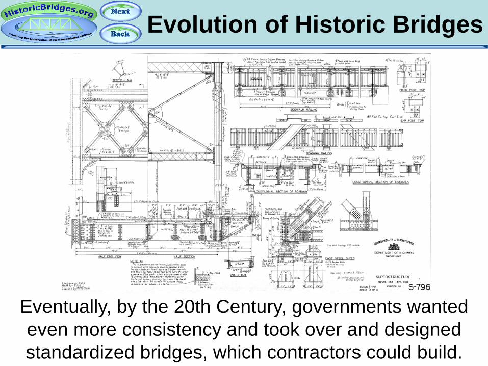
Eventually, by the 20th Century, governments wanted even more consistency and took over and designed standardized bridges, which contractors could build.

Evolution of Historic Bridges
Bridges from the earlier era often were prototypes, or otherwise examples of innovative technology of the time,
and they are singled out as historically significant.
However, HistoricBridges.org also considers the later standardized bridges that may have not been so
innovative to also be historic. They are representative examples from a period in history.
Part 2: Bridge Basics
An Introduction To Historic Bridges
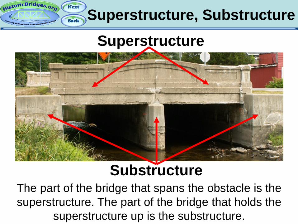
Superstructure, Substructure
The part of the bridge that spans the obstacle is the superstructure. The part of the bridge that holds the
superstructure up is the substructure.
Superstructure
Substructure
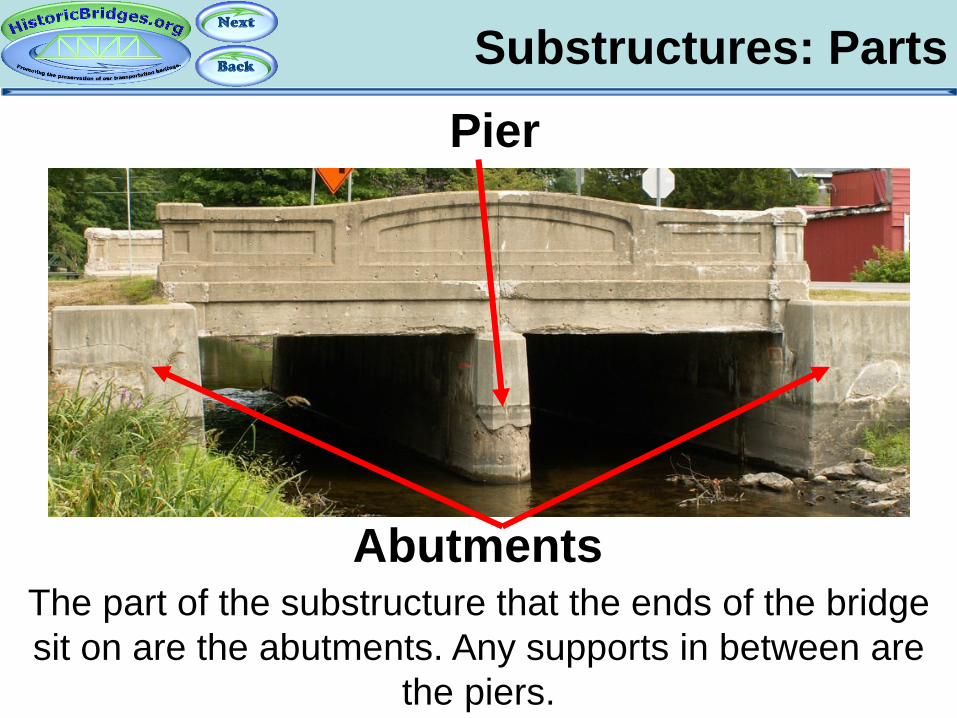
Substructures: Parts
The part of the substructure that the ends of the bridge sit on are the abutments. Any supports in between are
the piers.
Abutments
Pier
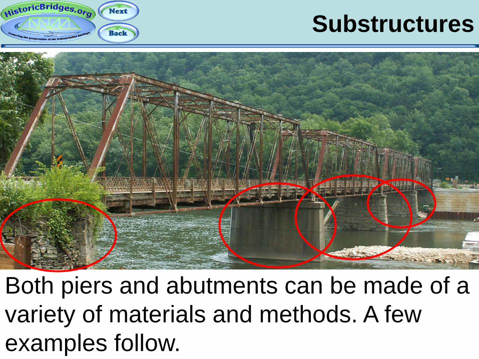
Substructures
Both piers and abutments can be made of a variety of materials and methods. A few examples follow.
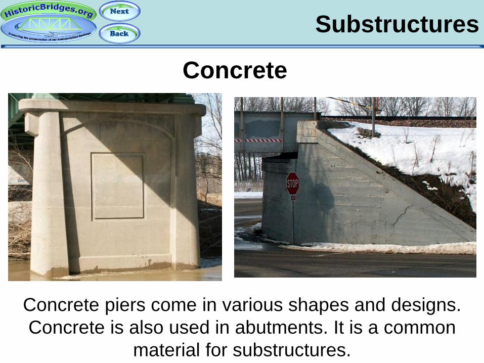
Substructures
Concrete piers come in various shapes and designs. Concrete is also used in abutments. It is a common
material for substructures.
Concrete
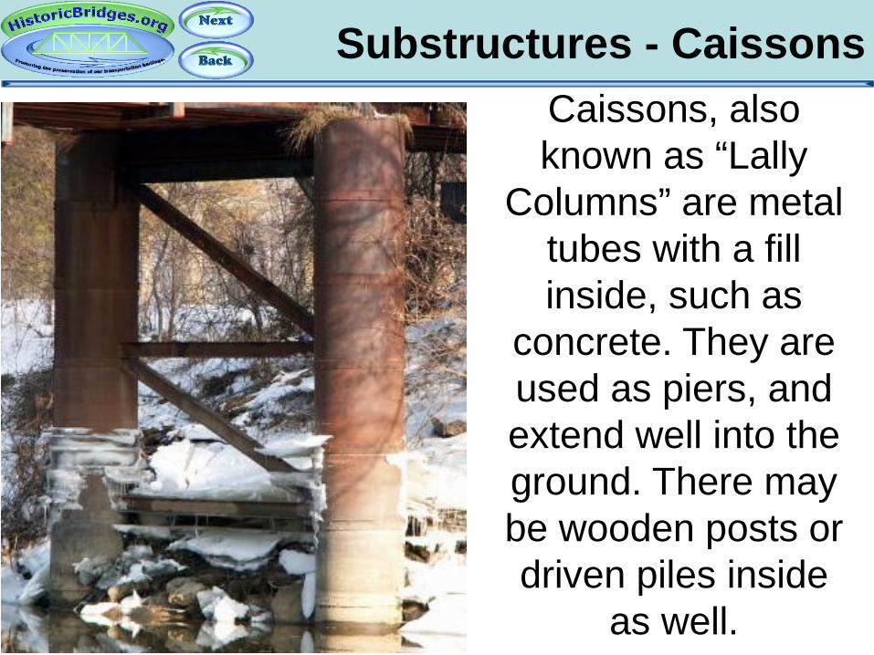
Substructures - Caissons
Caissons, also known as “Lally
Columns” are metal tubes with a fill inside, such as
concrete. They are used as piers, and extend well into the ground. There may be wooden posts or driven piles inside
as well.

Substructures
Refining The Vocabulary: Bent vs. Pier
Supports with multiple columns are called bents. Supports with a single column are simply called piers.
FYI: In casual discussion, bents may still be called piers.
Bent Pier

Substructures
Bents
Metal bents with a complex designs and extensive bracing systems (sometimes called towers) were
popular with high level railroad bridges.
Bent
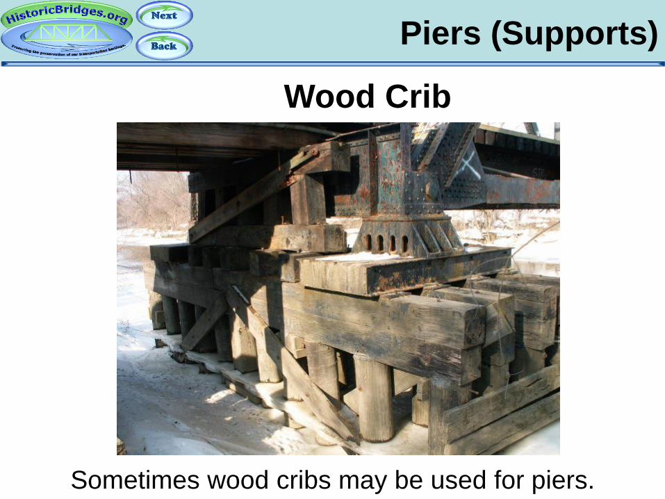
Piers (Supports)
Wood Crib
Sometimes wood cribs may be used for piers.

Substructures
Stone abutments and piers can be made of unshaped stones. The layout can be random, or it can be coursed, which means it is lined up in rows. Each row is a called a “course”.
Semi-Coursed Rubble
Random Rubble
Substructures
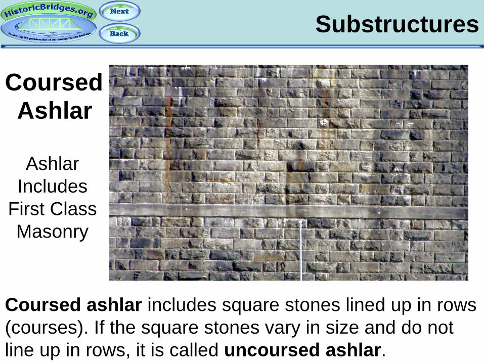
Coursed ashlar includes square stones lined up in rows (courses). If the square stones vary in size and do not line up in rows, it is called uncoursed ashlar.
Coursed Ashlar
Ashlar Includes
First Class Masonry

Abutments
Stone substructures may have iron or steel tie rods to help hold them together.
Substructures
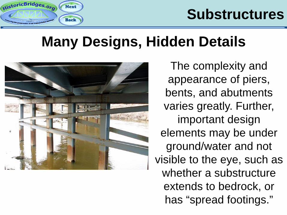
Many Designs, Hidden Details The complexity and appearance of piers, bents, and abutments varies greatly. Further,
important design elements may be under ground/water and not
visible to the eye, such as whether a substructure extends to bedrock, or has “spread footings.”
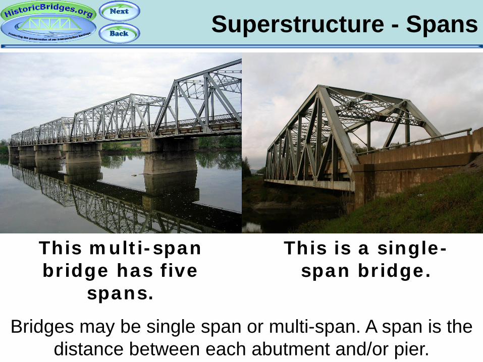
Superstructure - Spans
Bridges may be single span or multi-span. A span is the distance between each abutment and/or pier.
This multi-span bridge has five
spans.
This is a single-span bridge.

Superstructure – Span Types
Spans may be continuous or simple. Simple spans are essentially a series of single span bridges lined up on piers. Continuous spans are like long single-spans,
supported by piers between abutments.
Simple Spans Continuous Spans
Piers
Individual Spans

Simple Spans
Simple spans are structurally independent, each physically capable of being its own separate bridge and
functioning as such.
Piers
Simple Spans

Continuous Spans
Continuous spans are interconnected with their surrounding spans and require the presence of the
surrounding spans to function correctly
Simple Spans Piers
Continuous Spans
Pier

Superstructure – Skew
Bridges may be built with a skew, or angle, to them. Skewed bridges required more effort to engineer. They are also interesting to look at. With some bridge types, skew can drastically alter a bridge’s appearance. The
above bridge illustrates this well.

Superelevation
Curved bridges have a deck and superstructure that is higher on one side, to provide stability at higher speeds for bridge users. This is called superelevation, and can
often result in unusual looking piers and abutments.

Bearings
Bearings connect the bridge superstructure to the substructure. Bearings may be stationary (fixed) bearings or expansion bearings which give the bridge the ability to make small expansions, contractions, and movements, that occur with a changing environment.
Sole Plate
Masonry Plate Bearing
Substructure
Superstructure

Expansion Bearings
Rocker expansion bearings are common, and often feature a pin above the rocker as well. Some rocker bearings do not have pins, however.
Pinned Rocker Bearing
Rocker Bearing (No Pin)
Expansion Bearings
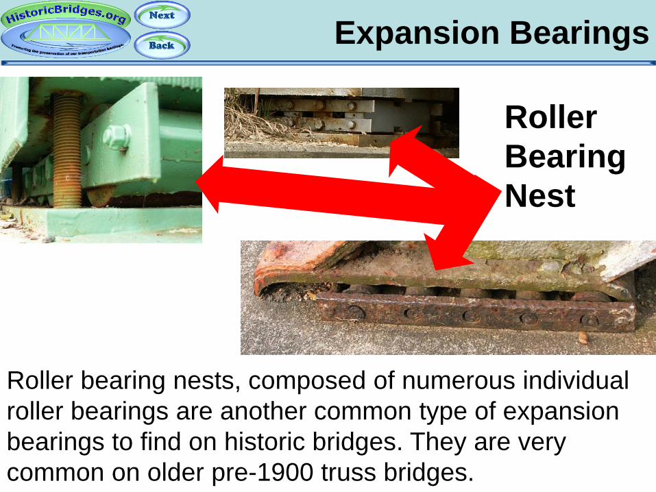
Roller bearing nests, composed of numerous individual roller bearings are another common type of expansion bearings to find on historic bridges. They are very common on older pre-1900 truss bridges.
Roller Bearing Nest

Decks
The surface of the bridge on which traffic is carried is called the deck. Decks come in a variety of materials. Some common types are concrete, wood, and metal grid/grate. The deck may be covered with another material like asphalt for ride quality or sealing purposes. This is called a wearing surface.

Decks: Deck Stringers
Some decks may have beams under them whose purpose is to hold the deck in place on the superstructure. These are called deck stringers. The above photo of a deck removal shows the parts.
Wooden deck
Superstructure
Deck stringers
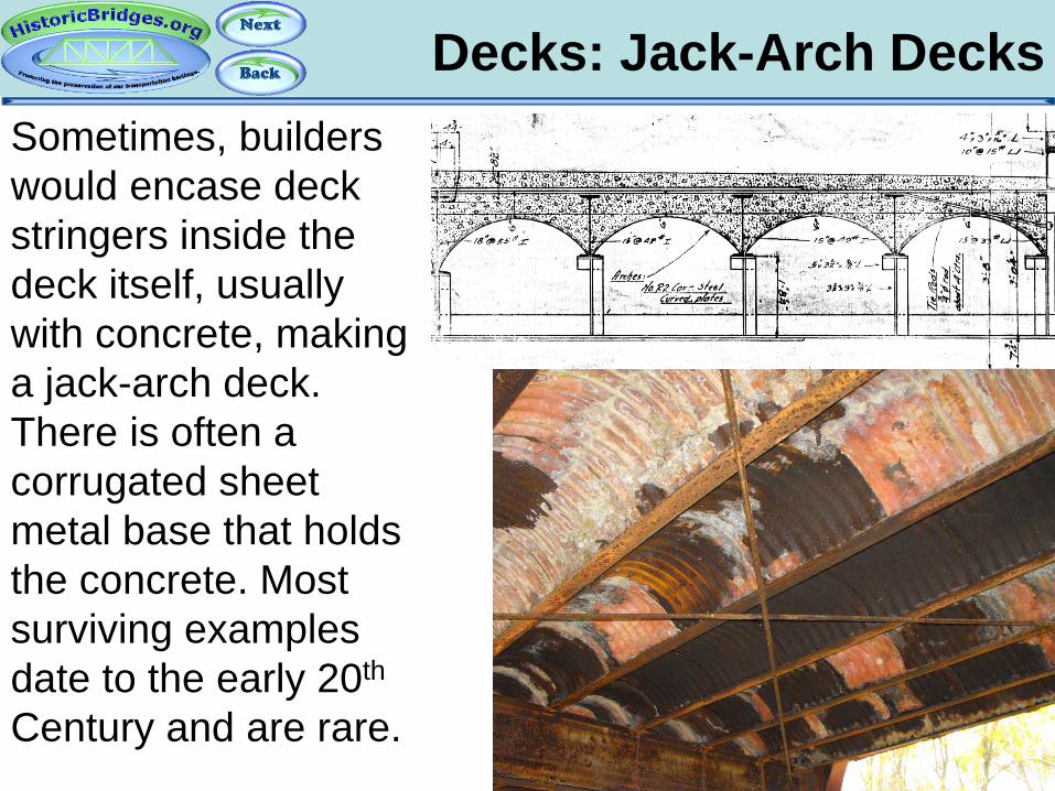
Decks: Jack-Arch Decks
Sometimes, builders would encase deck stringers inside the deck itself, usually with concrete, making a jack-arch deck. There is often a corrugated sheet metal base that holds the concrete. Most surviving examples date to the early 20th Century and are rare.
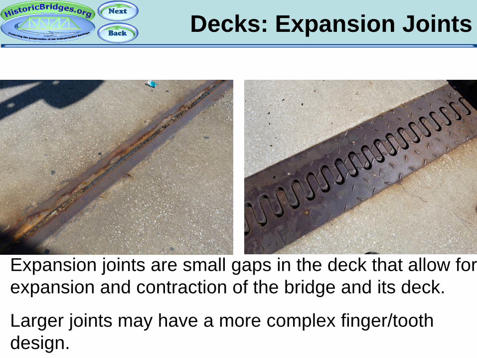
Decks: Expansion Joints
Expansion joints are small gaps in the deck that allow for expansion and contraction of the bridge and its deck.
Larger joints may have a more complex finger/tooth design.
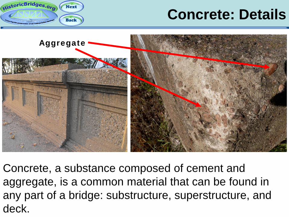
Concrete: Details
Concrete, a substance composed of cement and aggregate, is a common material that can be found in any part of a bridge: substructure, superstructure, and deck.
Aggregate
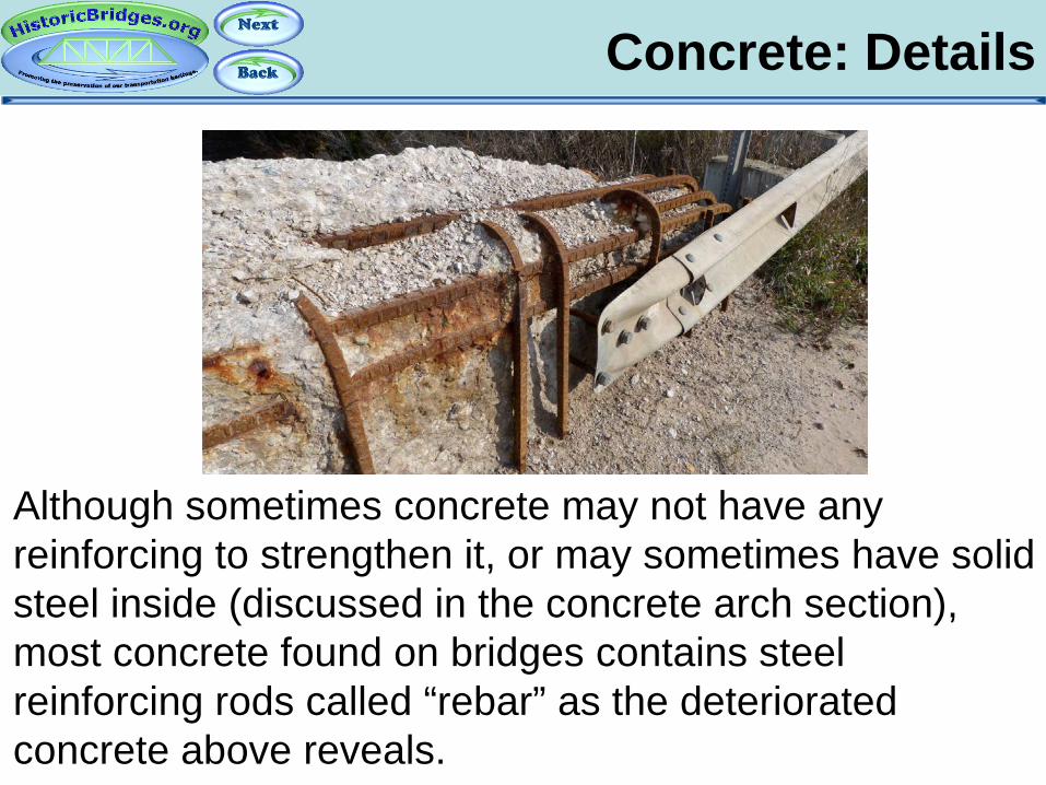
Concrete: Details
Although sometimes concrete may not have any reinforcing to strengthen it, or may sometimes have solid steel inside (discussed in the concrete arch section), most concrete found on bridges contains steel reinforcing rods called “rebar” as the deteriorated concrete above reveals.

Part 3: Metal Truss Bridges and the Basics
of Iron and Steel
An Introduction To Historic Bridges

The linked image cannot be displayed. The file may have been moved, renamed, or deleted. Verify that the link points to the correct file and location.
Truss Bridges
A metal truss bridge is a bridge whose main structure comes from a triangular framework of structural steel or iron.

The linked image cannot be displayed. The file may have been moved, renamed, or deleted. Verify that the link points to the correct file and location.
Iron and Steel
Looking at the iron and steel on a truss bridge is a good way to learn about iron and steel on any bridge.

Iron and Steel
Metal is usually steel or wrought iron. Cast iron was used, but is rare. Wrought iron is generally on older truss bridges, and tends to rust very little. Steel is stronger, on newer truss bridges, but more susceptible to rust. Field identification of either may be difficult without tools.
Wrought Iron Bridge Steel Bridge

Wrought Iron
Wrought iron has an interesting appearance when looked at in cross section because it has more slag
(waste material) in it. This eye bar was cut in half and you can see the slag appearing like the grain in wood.
Prepared Iron Sample Provided By Vern Mesler

American Standard Beams
Rolled iron and steel can come in the form of i-beams. The traditional kind, often found on old bridges, is the American Standard Beam, and features an “i” shape. The original designs feature a sloped flange.
Sloped Flange
American Standard Beams have a true “I”
shape.

Wide Flange Beams
The American Standard Beam was later replaced by the Wide Flange Beam. Unless they have been added at a later date, old truss bridges generally should not have these beams, which feature more of an “H” shape. Wide Flange Beams do not have a sloped flange.
No Sloped Flange
Wide Flange Beams have
more of an “H” shape.
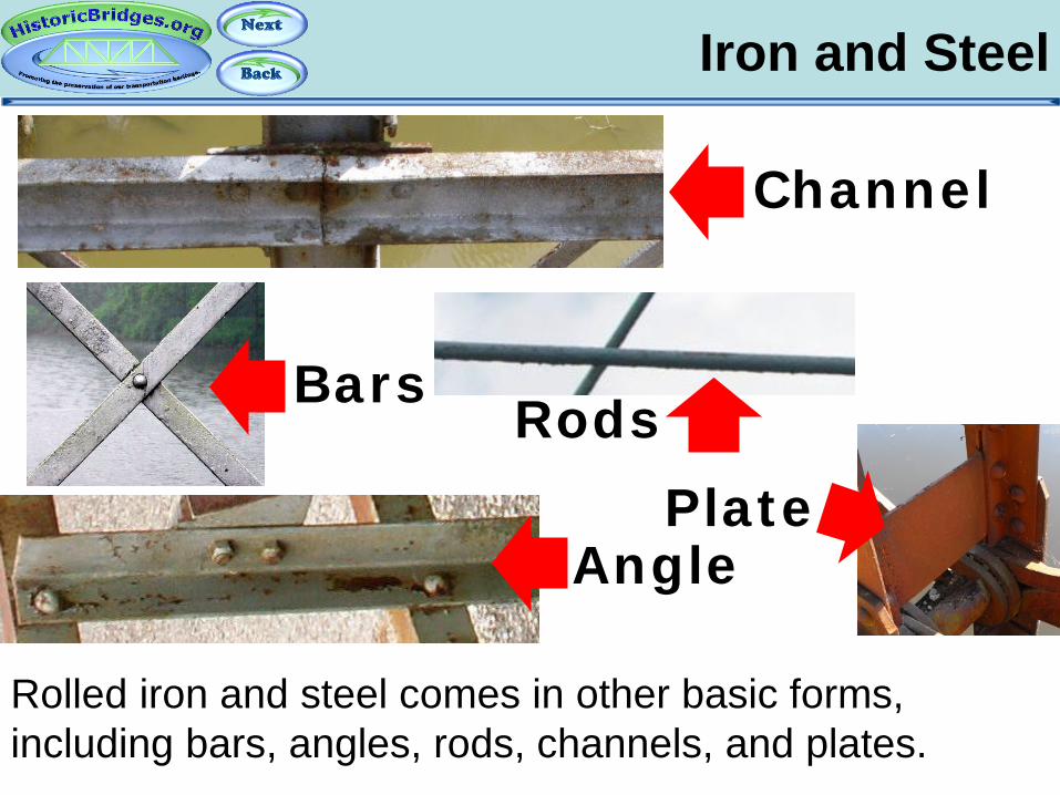
Iron and Steel
Rolled iron and steel comes in other basic forms, including bars, angles, rods, channels, and plates.
Channel
Bars
Angle
Rods Plate

Built-Up Iron and Steel
Before the ability to roll larger and stronger beams arrived, iron and steel elements were often riveted together to form larger and stronger beams. Such beams that are formed from smaller elements are built-up, sometimes called “fabricated” as well.

Built-Up Iron and Steel
A common way to hold the larger beams such as channels and angles together was to use bars and/or plates to connect them. They are usually connected in one of three ways: with battens, v-lacing, or lattice.
battens V-lacing
Lattice

Built-Up Iron and Steel
A side effect of v-lacing and lattice is that it adds greatly to the beauty of the bridge, creating an even more defined geometric art and complexity in the truss bridge.
More V-lacing and Lattice
Less V-lacing and Lattice
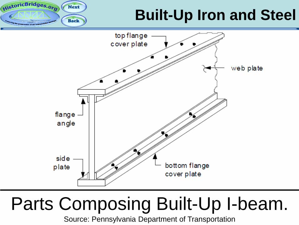
Built-Up Iron and Steel
Parts Composing Built-Up I-beam. Source: Pennsylvania Department of Transportation

Columns
A special type of built-up beam was developed in the 1800s and patented by their respective companies. Many were designed and promoted, but only two major types remain today (both rare) and are called Phoenix and Keystone Columns.

Keystone Columns
One type is the Keystone Column. It is noted for having a polygonal shape with flat sides and not a true circular shape. It was often used as the top chord for bowstring truss bridges built by the Wrought Iron Bridge Company, which will be discussed later.
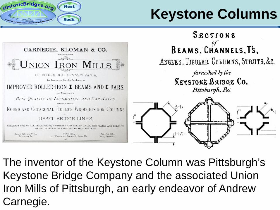
Keystone Columns
The inventor of the Keystone Column was Pittsburgh’s Keystone Bridge Company and the associated Union Iron Mills of Pittsburgh, an early endeavor of Andrew Carnegie.

Phoenix Columns
The other type is the Phoenix Column. These columns feature a circular shape to them. They were generally used on pin-connected truss bridges, for various members and bracing.

Phoenix Columns
Phoenix Columns were invented and patented by Phoenix Iron Company of Phoenixville and Philadelphia, and the related Phoenix Bridge Company built bridges with them.
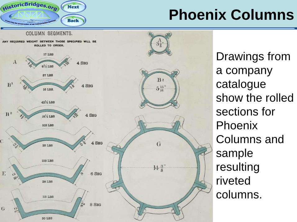
Phoenix Columns
Drawings from a company catalogue show the rolled sections for Phoenix Columns and sample resulting riveted columns.

Eye Bars
Finally, eye bars may be present on the bridge. They come in two forms, loop-welded and up-set.
Loop-Welded
Up-Set Has circular
hole.
Has teardrop-shaped hole.

Eye Bars
On certain eye bars, generally very long ones, and if they are in good condition, you may be able to find two tiny little indentations at a set distance apart from each other. These were used as measuring points to test the tension of the eye bar (make sure it did not stretch), at a point where two bars were forge-welded together to make it a longer bar. You might feel the slight bulge or see faint hammer marks in between the dots, where the forge weld took place. Research Credit: Vern Mesler
Forge Weld

Steel and Iron Fabricators
Look closely at the iron and steel on bridges and you might find the name of the mill that the metal was fabricated by on it. Common names include Carnegie, Cambria, and Jones and Laughlin (Jones and Laughlins for pre-1905 beams).

Steel and Iron Fabricators
HistoricBridges.org has compiled a special page dedicated to cataloging the various iron and steel brands found on bridges. Since some companies had different years of operation, changed their names at different periods in history, and/or adjusted the font and appearance of their logo, this information can help date iron and steel on a bridge.
historicbridges.org/info/brands/
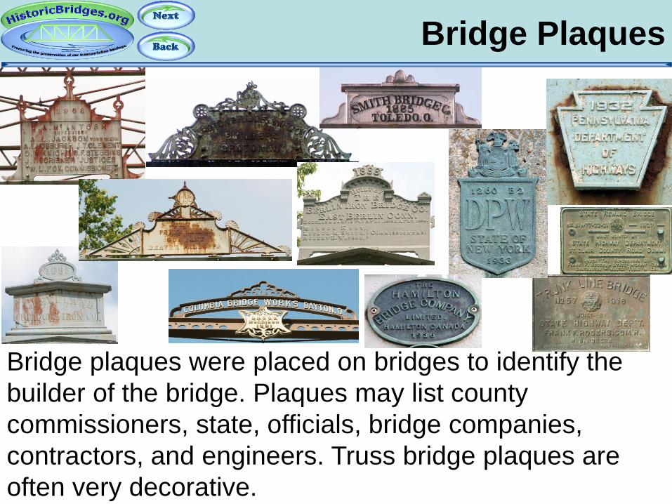
Bridge Plaques
Bridge plaques were placed on bridges to identify the builder of the bridge. Plaques may list county commissioners, state, officials, bridge companies, contractors, and engineers. Truss bridge plaques are often very decorative.
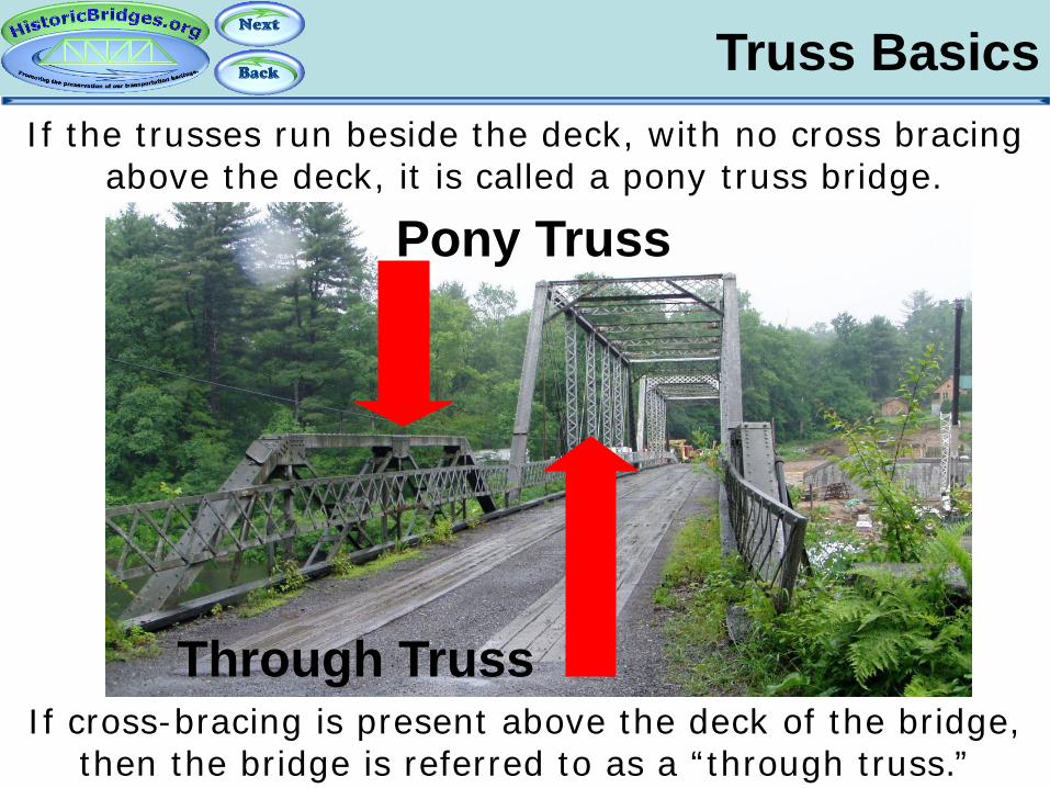
Truss Basics If the trusses run beside the deck, with no cross bracing
above the deck, it is called a pony truss bridge.
If cross-bracing is present above the deck of the bridge, then the bridge is referred to as a “through truss.”
Pony Truss
Through Truss

Truss Basics
Trusses may run under the deck: these are called simply Deck truss bridges.
Deck Truss
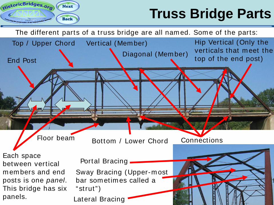
The different parts of a truss bridge are all named. Some of the parts: Top / Upper Chord Vertical (Member)
Diagonal (Member)
Bottom / Lower Chord
Portal Bracing Sway Bracing (Upper-most bar sometimes called a “strut”) Lateral Bracing
Floor beam Connections
End Post
Each space between vertical members and end posts is one panel. This bridge has six panels.
Truss Bridge Parts
Hip Vertical (Only the verticals that meet the top of the end post)
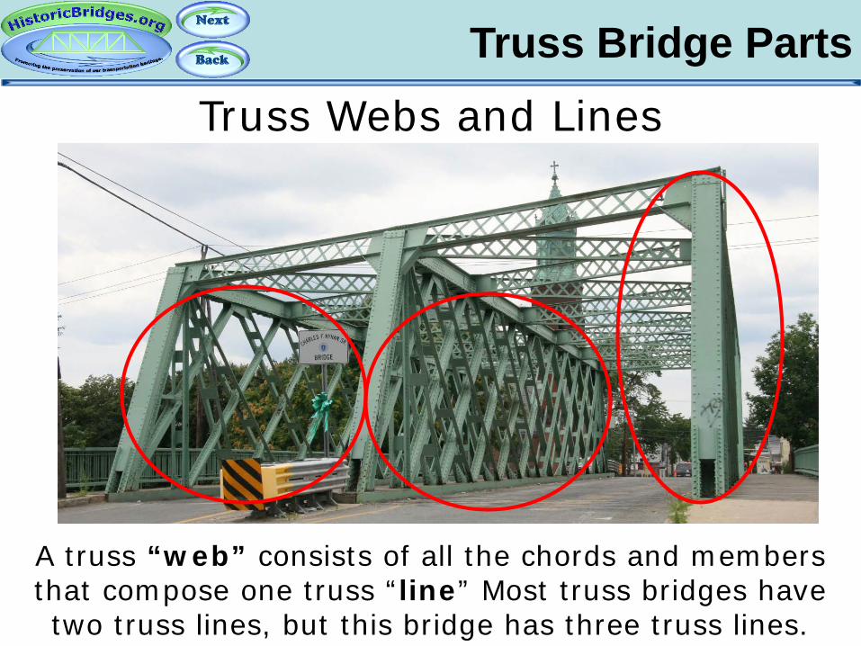
Truss Webs and Lines
Truss Bridge Parts
A truss “web” consists of all the chords and members that compose one truss “line” Most truss bridges have two truss lines, but this bridge has three truss lines.
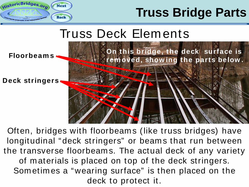
Truss Deck Elements
Truss Bridge Parts
Often, bridges with floorbeams (like truss bridges) have longitudinal “deck stringers” or beams that run between
the transverse floorbeams. The actual deck of any variety of materials is placed on top of the deck stringers.
Sometimes a “wearing surface” is then placed on the deck to protect it.
Floorbeams
Deck stringers
On this bridge, the deck surface is removed, showing the parts below.

Truss Bridge Parts
Pony trusses may have a vertical member that extends or angles out beyond the edges of the bridge. These are
to stabilize the bridge and are called outriggers or sometimes buttresses.
Pony Truss: Outriggers (Buttresses)

The chords and members of a truss bridge experience strain in the form of tension (stretching apart) and
compression (squeezing together). Engineers often picked different types of materials and designs for the different parts of a bridge based on these forces. An
example is shown above.
Truss Bridge Forces
Tension Compression

Truss Bridge Connections
The pieces of the framework of a truss bridge are held together by connections, sometimes also called joints.
Most connections on historic bridges are either riveted or pinned, but can also be bolted or welded.
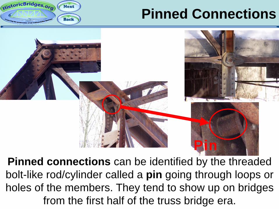
Pinned Connections
Pinned connections can be identified by the threaded bolt-like rod/cylinder called a pin going through loops or holes of the members. They tend to show up on bridges
from the first half of the truss bridge era.
Pin

Riveted Connections
Riveted connections are identified by a “gusset plate” which diagonals and vertical members are riveted to,
and no pin is present. These connections tend to show up in the second half of the truss bridge era.

Other Connection Types
Welded and bolted connections are similar to riveted connections, and generally are only found on newer
bridges or altered old bridges, although there are some exceptions.
Bolted and Welded Connections
Bolted Welded
Other Connection Types
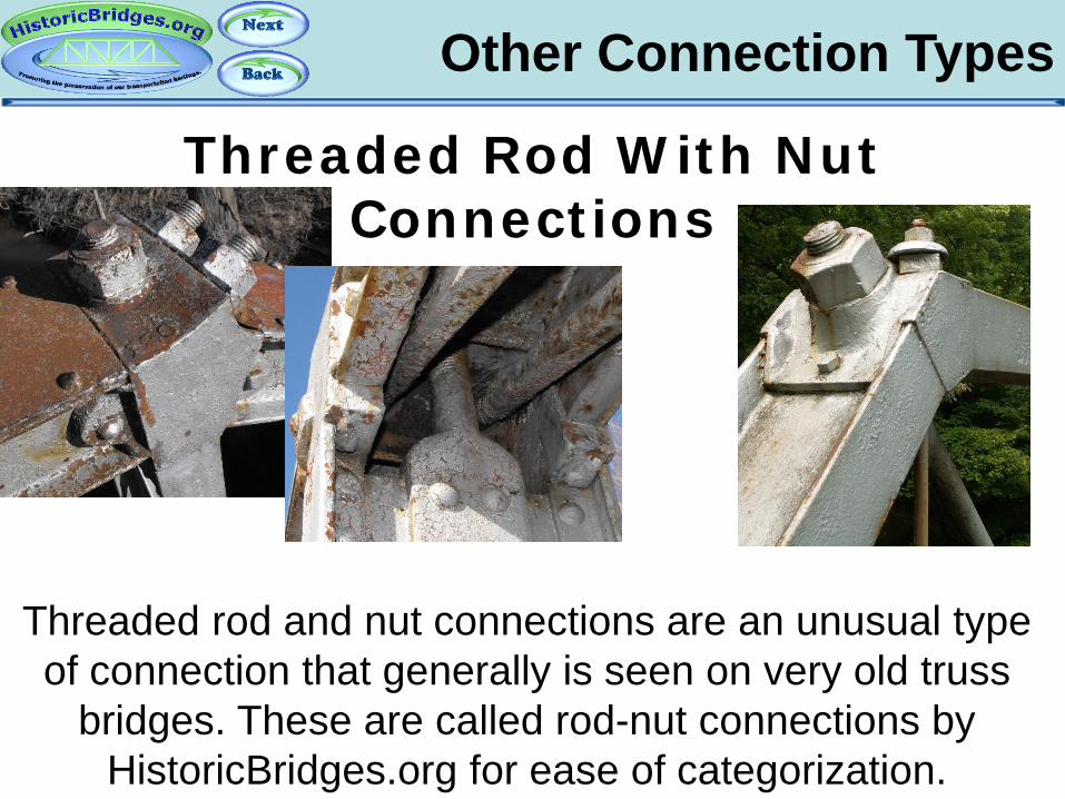
Threaded rod and nut connections are an unusual type of connection that generally is seen on very old truss
bridges. These are called rod-nut connections by HistoricBridges.org for ease of categorization.
Threaded Rod With Nut Connections
Part 4: Truss Bridge Configurations
An Introduction To Historic Bridges

Truss Configurations Pratt
Overview: One of the two most common configurations, it tends to occupy the earlier half of the truss bridge era, but was used throughout. Originally developed by Thomas and Caleb Pratt in 1844. Appearance: Diagonal members angle toward the center and bottom of bridge.

Truss Configurations Pratt – Additional Notes
A Pratt may have additional diagonals called “counters”, sometimes of a smaller size, that do not follow the
standard pattern to form an “X” shape on panels, usually toward the center, and may have turnbuckles.
Counters

Truss Configurations Pratt - Half-Hip
Some smaller pony truss bridges may not feature a hip vertical member, and they are called half-hip Pratt pony truss bridges. Those that feature the hip vertical may be
called full-slope Pratt pony truss bridges.
Full-Slope Half-Hip
Truss Configurations
Whipple (Double-Intersection Pratt)
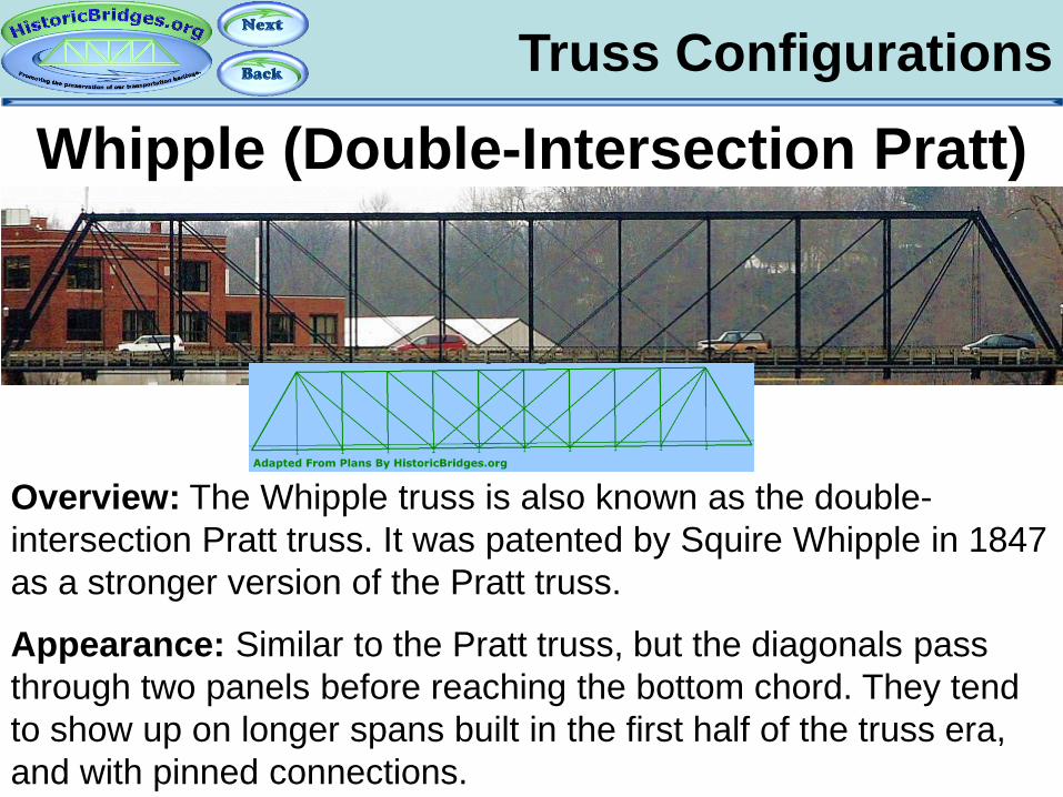
Overview: The Whipple truss is also known as the double-intersection Pratt truss. It was patented by Squire Whipple in 1847 as a stronger version of the Pratt truss.
Appearance: Similar to the Pratt truss, but the diagonals pass through two panels before reaching the bottom chord. They tend to show up on longer spans built in the first half of the truss era, and with pinned connections.
Truss Configurations Triple Intersection Pratt
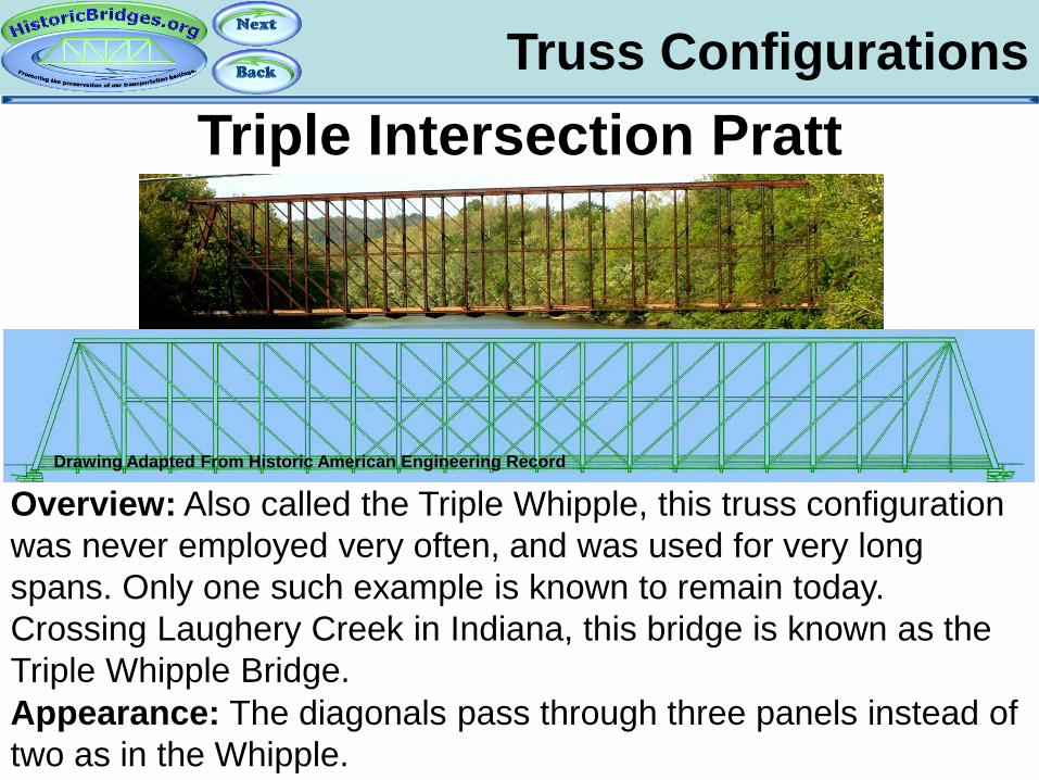
Overview: Also called the Triple Whipple, this truss configuration was never employed very often, and was used for very long spans. Only one such example is known to remain today. Crossing Laughery Creek in Indiana, this bridge is known as the Triple Whipple Bridge. Appearance: The diagonals pass through three panels instead of two as in the Whipple.
Drawing Adapted From Historic American Engineering Record
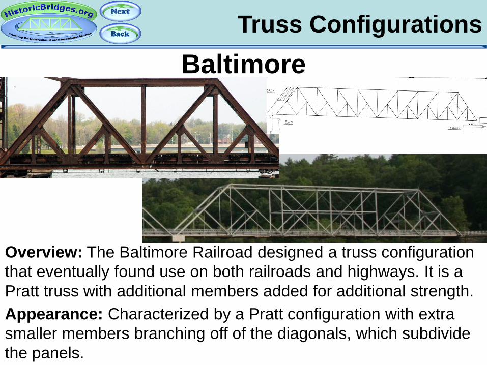
Truss Configurations Baltimore
Overview: The Baltimore Railroad designed a truss configuration that eventually found use on both railroads and highways. It is a Pratt truss with additional members added for additional strength. Appearance: Characterized by a Pratt configuration with extra smaller members branching off of the diagonals, which subdivide the panels.

Truss Configurations Parker Overview: Charles
H. Parker modified the Pratt design to create what became known as the Parker truss configuration. This design allowed one to use less materials to get the a similar load capacity. The downside was the more complex design. Appearance: Characterized by an arch-shaped (polygonal) top chord, with diagonals that follow the Pratt configuration.
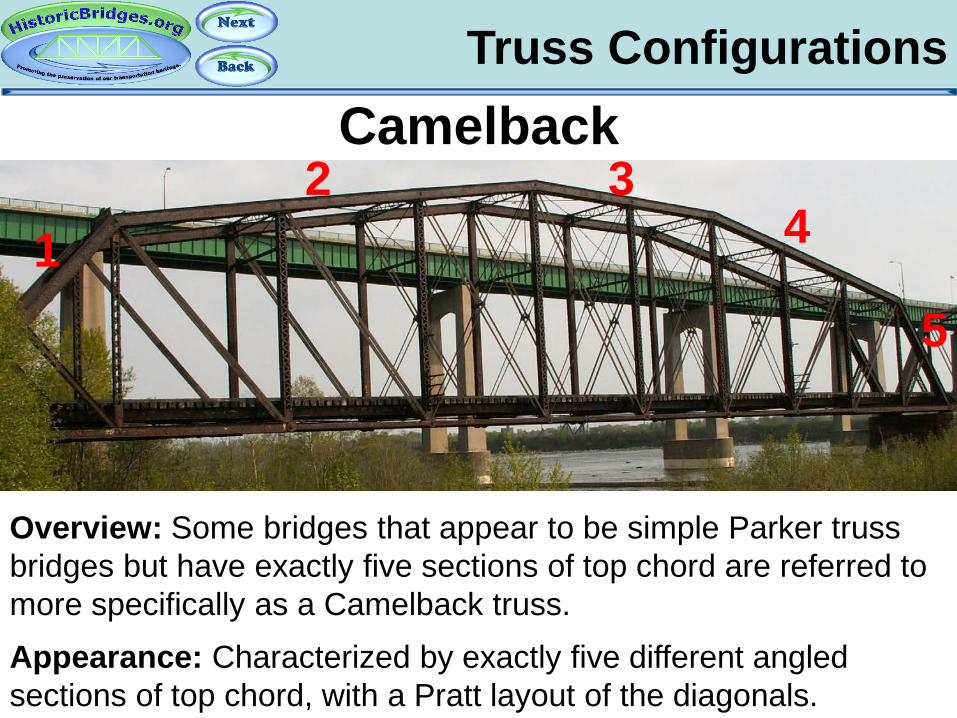
Truss Configurations Camelback
Overview: Some bridges that appear to be simple Parker truss bridges but have exactly five sections of top chord are referred to more specifically as a Camelback truss. Appearance: Characterized by exactly five different angled sections of top chord, with a Pratt layout of the diagonals.
1 2 3
4
5
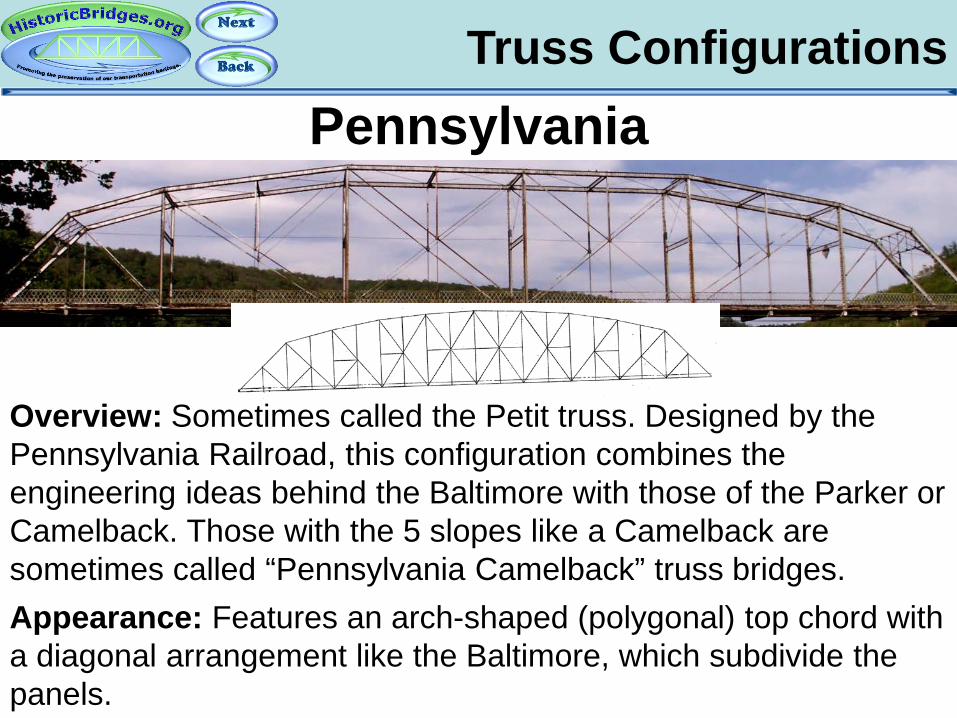
Truss Configurations Pennsylvania
Overview: Sometimes called the Petit truss. Designed by the Pennsylvania Railroad, this configuration combines the engineering ideas behind the Baltimore with those of the Parker or Camelback. Those with the 5 slopes like a Camelback are sometimes called “Pennsylvania Camelback” truss bridges. Appearance: Features an arch-shaped (polygonal) top chord with a diagonal arrangement like the Baltimore, which subdivide the panels.
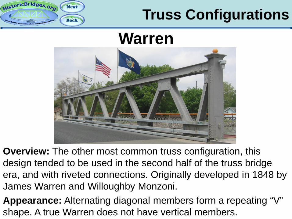
Truss Configurations Warren
Appearance: Alternating diagonal members form a repeating “V” shape. A true Warren does not have vertical members.
Overview: The other most common truss configuration, this design tended to be used in the second half of the truss bridge era, and with riveted connections. Originally developed in 1848 by James Warren and Willoughby Monzoni.
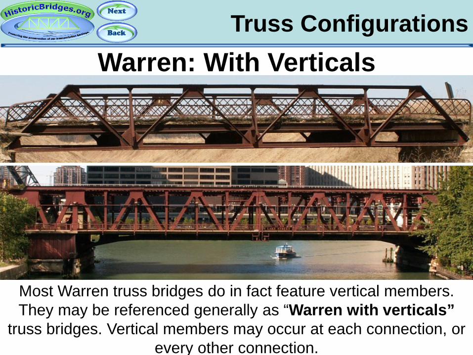
Truss Configurations Warren: With Verticals
Most Warren truss bridges do in fact feature vertical members. They may be referenced generally as “Warren with verticals”
truss bridges. Vertical members may occur at each connection, or every other connection.

Truss Configurations Double-Intersection Warren
Overview: Often called simply the Double Warren, this is an uncommon truss configuration. Bridges with this configuration often have riveted connections. Appearance: Looks like two Warren trusses offset and superimposed on each other, forming a repeating “X” shape.

Truss Configurations Lattice Truss
Overview: An adaptation of Warren truss technology that tends to show up on railroad bridges and with riveted connections. This category includes any multi-intersection Warren, generally beyond Double-Intersection (ie triple, quadruple, quintuple)
Appearance: Multiple Warren trusses offset and superimposed on each other, forming a lattice pattern.
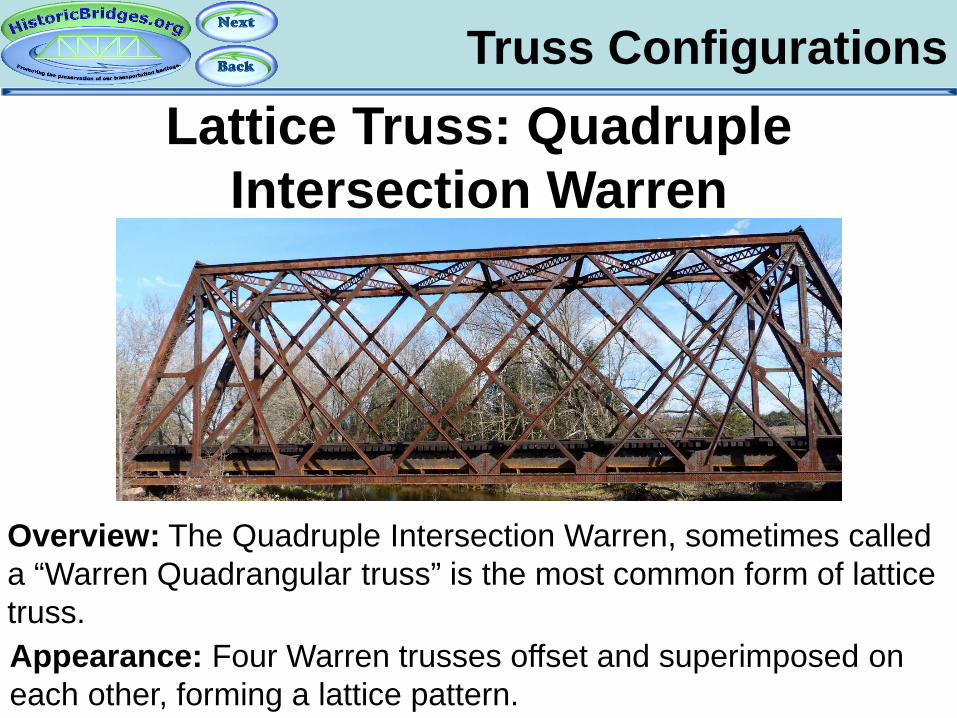
Truss Configurations Lattice Truss: Quadruple
Intersection Warren
Overview: The Quadruple Intersection Warren, sometimes called a “Warren Quadrangular truss” is the most common form of lattice truss. Appearance: Four Warren trusses offset and superimposed on each other, forming a lattice pattern.

Truss Configurations Lattice Truss: Triple Intersection
Warren
Overview: The Triple Intersection Warren is much less common than the Quadruple Intersection Warren truss. Appearance: Three Warren trusses offset and superimposed on each other, forming a lattice pattern.
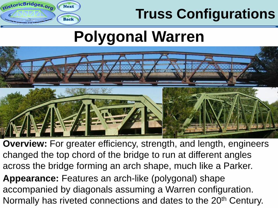
Truss Configurations Polygonal Warren
Overview: For greater efficiency, strength, and length, engineers changed the top chord of the bridge to run at different angles across the bridge forming an arch shape, much like a Parker. Appearance: Features an arch-like (polygonal) shape accompanied by diagonals assuming a Warren configuration. Normally has riveted connections and dates to the 20th Century.
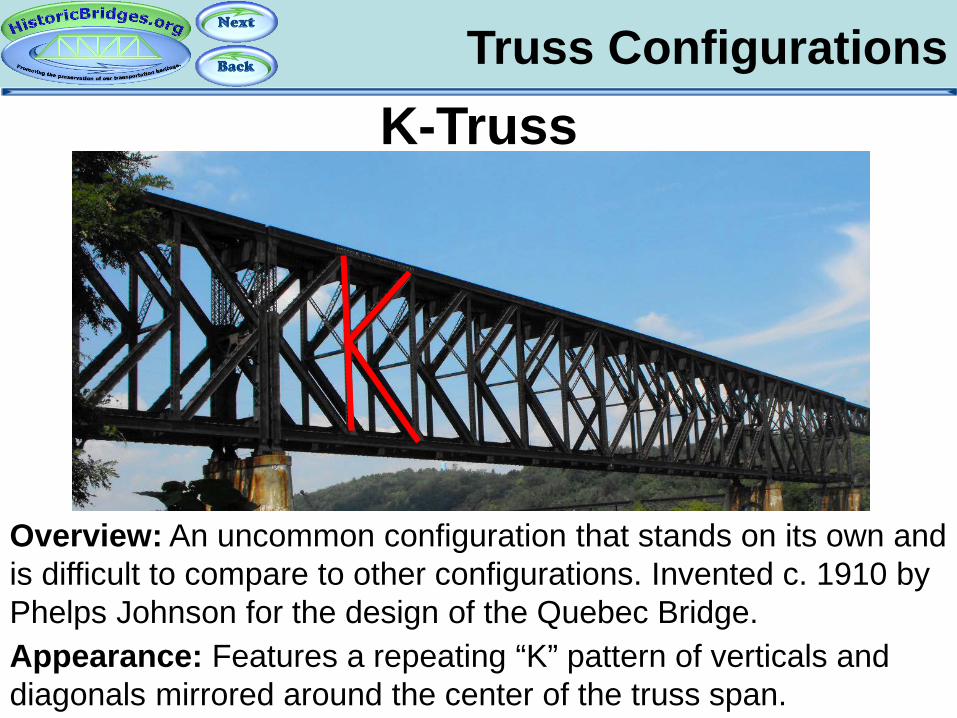
Truss Configurations K-Truss
Overview: An uncommon configuration that stands on its own and is difficult to compare to other configurations. Invented c. 1910 by Phelps Johnson for the design of the Quebec Bridge. Appearance: Features a repeating “K” pattern of verticals and diagonals mirrored around the center of the truss span.

Truss Configurations Kingpost
Overview: An extremely rare truss configuration, this was an early truss design used for short crossings. Appearance: Features exactly one vertical member and two inclined end posts.
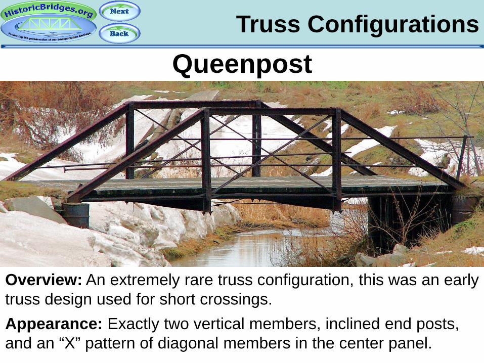
Truss Configurations Queenpost
Overview: An extremely rare truss configuration, this was an early truss design used for short crossings. Appearance: Exactly two vertical members, inclined end posts, and an “X” pattern of diagonal members in the center panel.
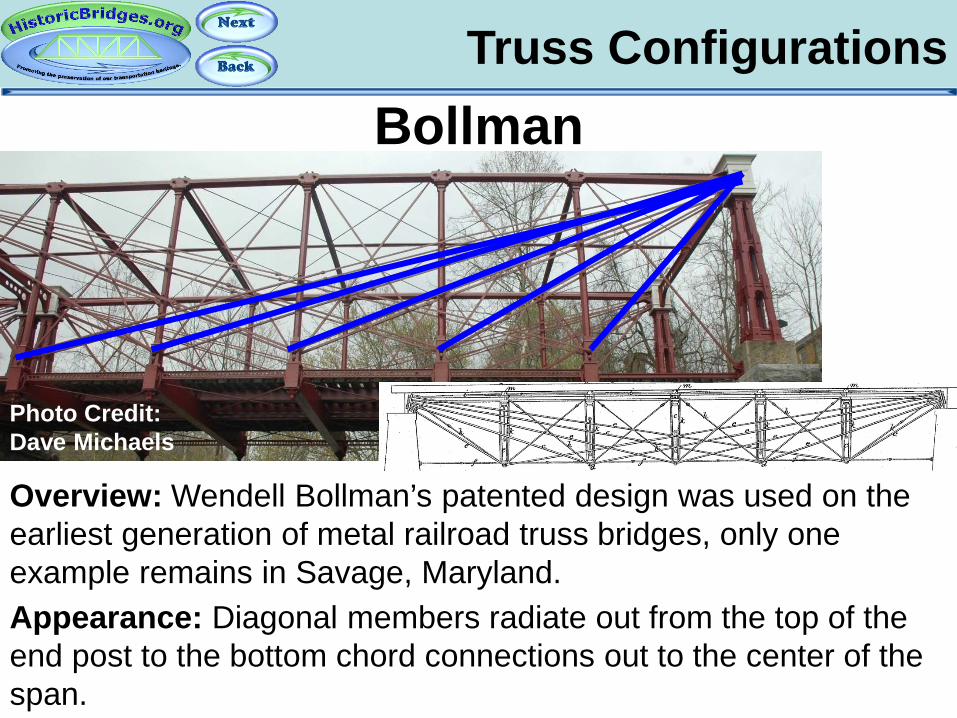
Truss Configurations Bollman
Overview: Wendell Bollman’s patented design was used on the earliest generation of metal railroad truss bridges, only one example remains in Savage, Maryland. Appearance: Diagonal members radiate out from the top of the end post to the bottom chord connections out to the center of the span.
Photo Credit: Dave Michaels
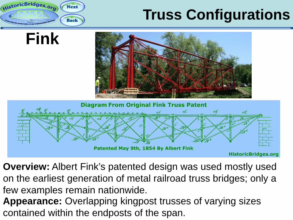
Truss Configurations Fink
Overview: Albert Fink’s patented design was used mostly used on the earliest generation of metal railroad truss bridges; only a few examples remain nationwide. Appearance: Overlapping kingpost trusses of varying sizes contained within the endposts of the span.
Photo Credit: Dave Michaels
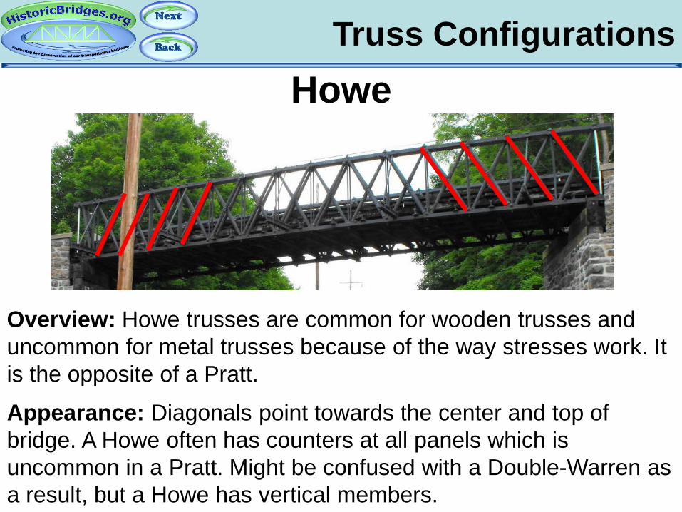
Truss Configurations Howe
Overview: Howe trusses are common for wooden trusses and uncommon for metal trusses because of the way stresses work. It is the opposite of a Pratt.
Appearance: Diagonals point towards the center and top of bridge. A Howe often has counters at all panels which is uncommon in a Pratt. Might be confused with a Double-Warren as a result, but a Howe has vertical members.
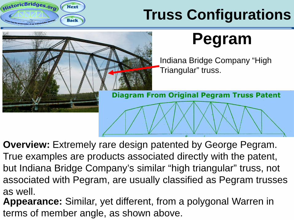
Truss Configurations Pegram
Overview: Extremely rare design patented by George Pegram. True examples are products associated directly with the patent, but Indiana Bridge Company’s similar “high triangular” truss, not associated with Pegram, are usually classified as Pegram trusses as well. Appearance: Similar, yet different, from a polygonal Warren in terms of member angle, as shown above.
Indiana Bridge Company “High Triangular” truss.
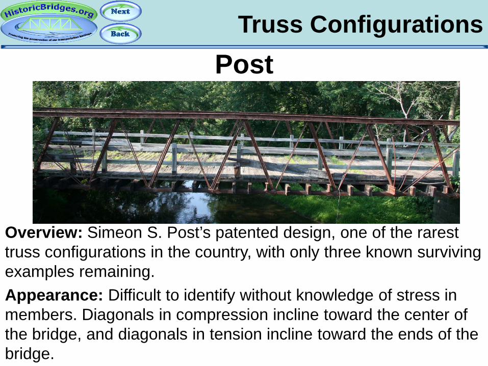
Truss Configurations Post
Overview: Simeon S. Post’s patented design, one of the rarest truss configurations in the country, with only three known surviving examples remaining. Appearance: Difficult to identify without knowledge of stress in members. Diagonals in compression incline toward the center of the bridge, and diagonals in tension incline toward the ends of the bridge.
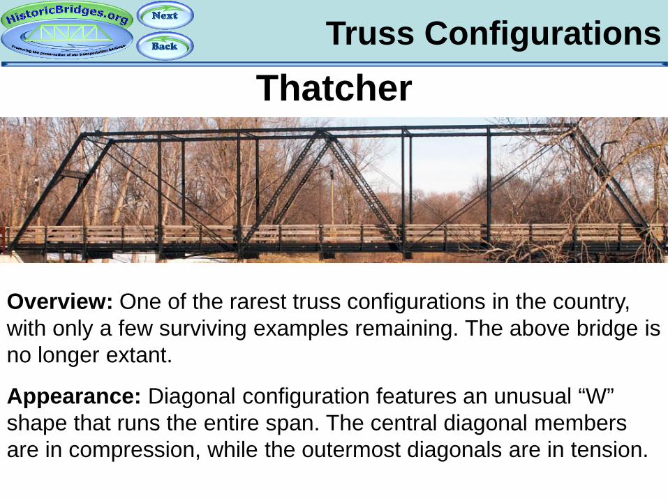
Truss Configurations Thatcher
Overview: One of the rarest truss configurations in the country, with only a few surviving examples remaining. The above bridge is no longer extant.
Appearance: Diagonal configuration features an unusual “W” shape that runs the entire span. The central diagonal members are in compression, while the outermost diagonals are in tension.
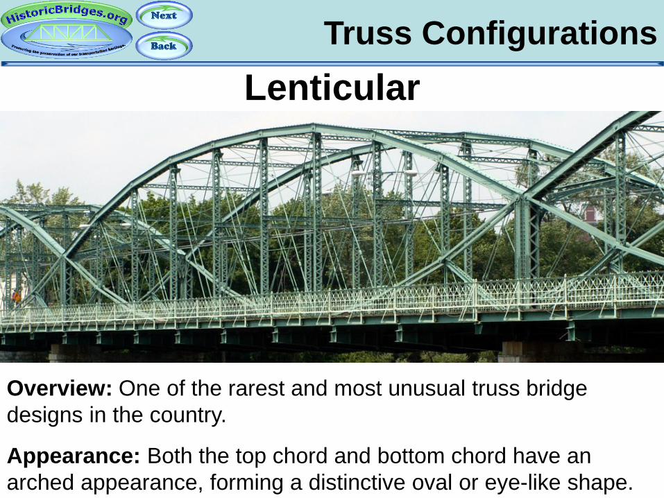
Truss Configurations Lenticular
Overview: One of the rarest and most unusual truss bridge designs in the country.
Appearance: Both the top chord and bottom chord have an arched appearance, forming a distinctive oval or eye-like shape.
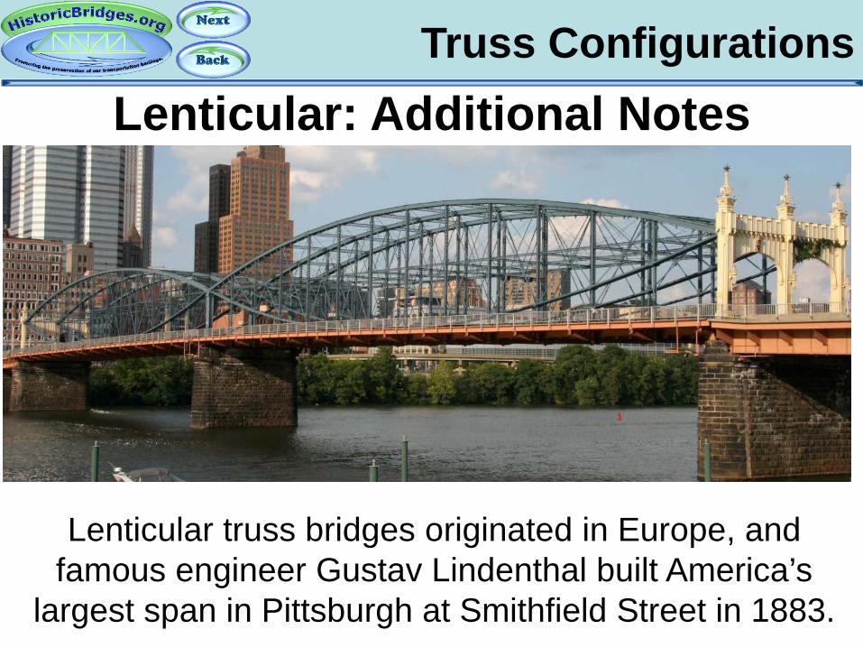
Truss Configurations Lenticular: Additional Notes
Lenticular truss bridges originated in Europe, and famous engineer Gustav Lindenthal built America’s
largest span in Pittsburgh at Smithfield Street in 1883.

Truss Configurations Lenticular: Additional Notes
Aside from Smithfield Street Bridge, all other lenticular truss bridges in the United States were built by the Corrugated Metal Company, which later became the Berlin Iron Bridge Company. This East Berlin, CT company held a patent for their variety of lenticular truss. Sometimes, the East Berlin lenticular trusses are described as “Jarvis-Douglas Parabolic Trusses” after the names of the involved East Berlin engineers/inventors.

Truss Configurations Bailey
Overview: Developed during World War II as a bridge type that was portable, quick to erect, and easy to adjust for different loads and spans. A late truss design, and still built today. Only the older and World War II surplus examples should be considered historic. Appearance: A unique design of pony truss composed of modular X-shaped panels. Height and width varies.
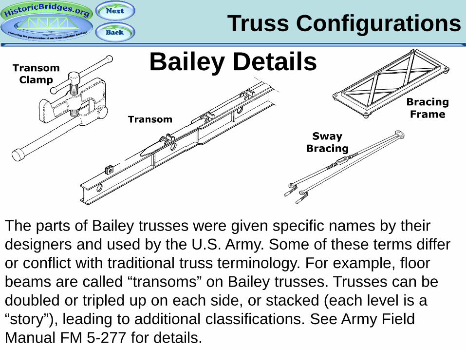
Truss Configurations Bailey Details
The parts of Bailey trusses were given specific names by their designers and used by the U.S. Army. Some of these terms differ or conflict with traditional truss terminology. For example, floor beams are called “transoms” on Bailey trusses. Trusses can be doubled or tripled up on each side, or stacked (each level is a “story”), leading to additional classifications. See Army Field Manual FM 5-277 for details.
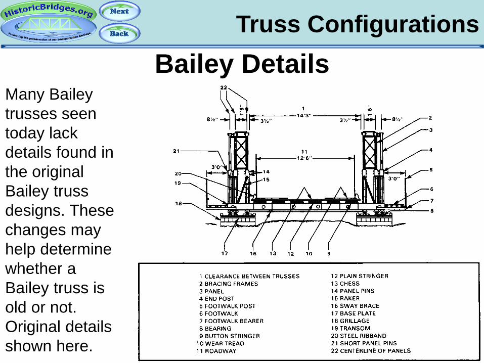
Truss Configurations Bailey Details
Many Bailey trusses seen today lack details found in the original Bailey truss designs. These changes may help determine whether a Bailey truss is old or not. Original details shown here.

Truss Configurations Bailey Classifications
The adaptive nature of the Bailey truss means that optionally, each truss line can consist of two panels side-by-side (called a double truss) and additionally, an additional row of panels can be placed on top of the first row adding a “story” to the truss. Bailey trusses are described by observing these configurations. Typical combinations described in the Army manual are shown here.
Truss Configurations Other Truss Types
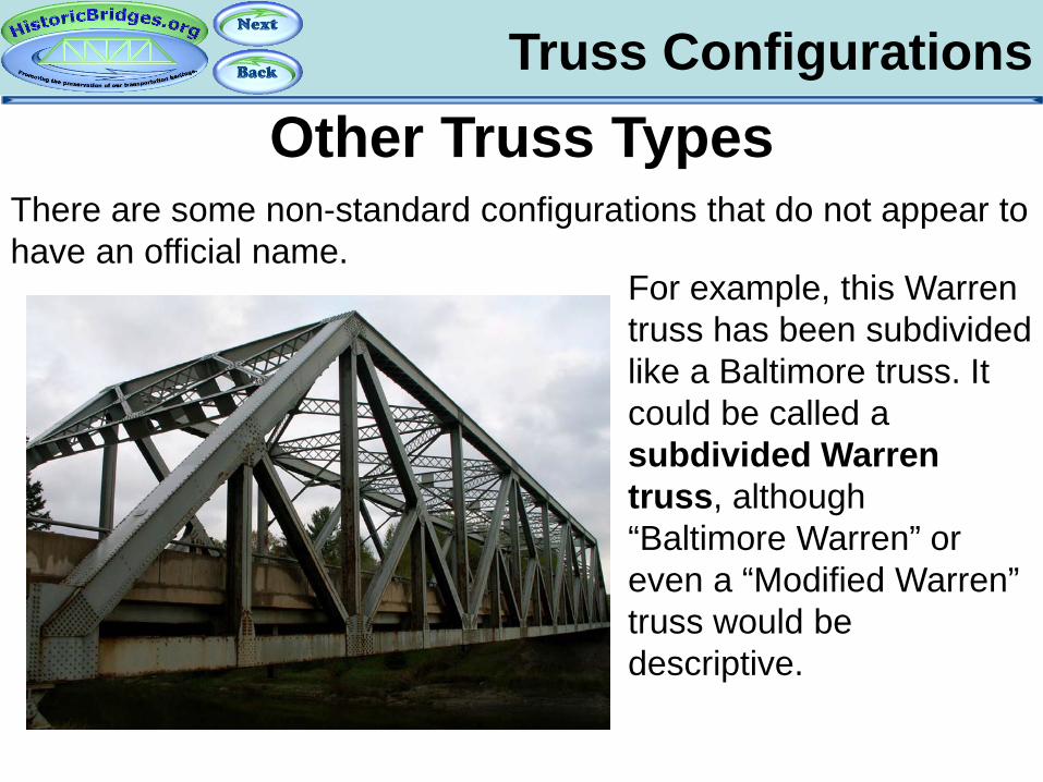
For example, this Warren truss has been subdivided like a Baltimore truss. It could be called a subdivided Warren truss, although “Baltimore Warren” or even a “Modified Warren” truss would be descriptive.
There are some non-standard configurations that do not appear to have an official name.
Bowstring Truss Bridges
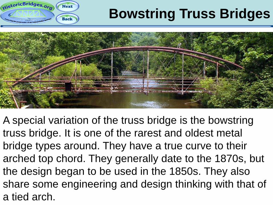
A special variation of the truss bridge is the bowstring truss bridge. It is one of the rarest and oldest metal bridge types around. They have a true curve to their arched top chord. They generally date to the 1870s, but the design began to be used in the 1850s. They also share some engineering and design thinking with that of a tied arch.

Bowstring Truss Bridges
Bridge companies at the time designed the bridges using their own ideas and patents. Thus, bowstring bridges have their own distinctive appearance based on what company built them.
Bowstring Truss Bridges
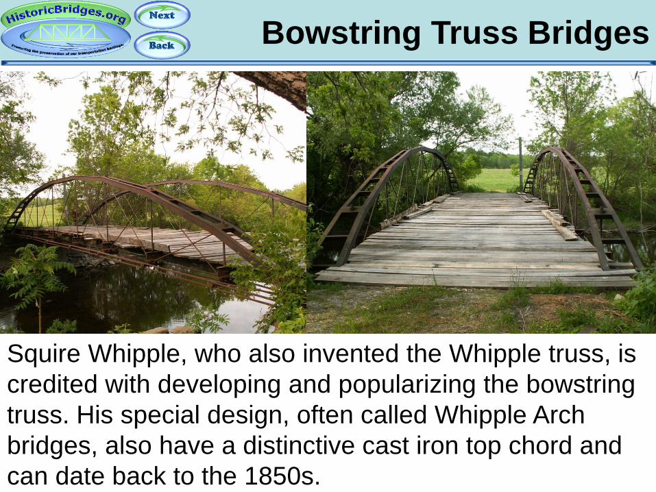
Squire Whipple, who also invented the Whipple truss, is credited with developing and popularizing the bowstring truss. His special design, often called Whipple Arch bridges, also have a distinctive cast iron top chord and can date back to the 1850s.

Bowstring Truss Bridges
The Wrought Iron Bridge Company of Canton Ohio built bowstrings that often used Keystone-style column top chords, and also used a lot of lattice on built-up members for larger bridges.
Bowstring Truss Bridges
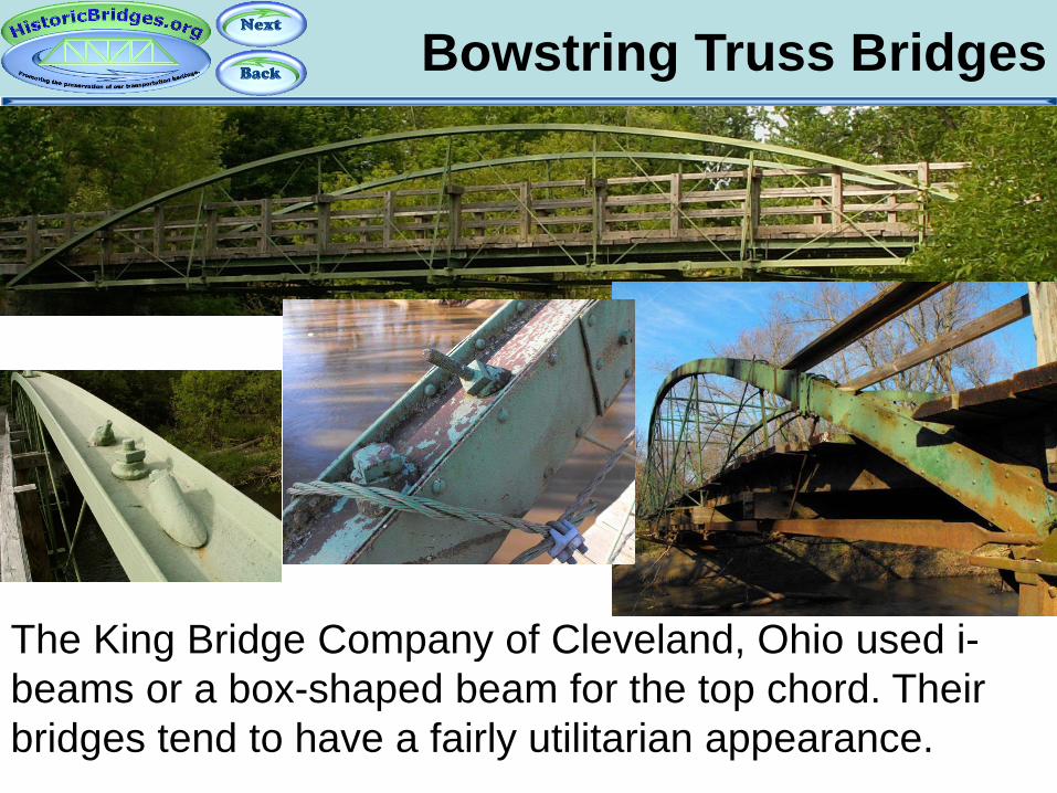
The King Bridge Company of Cleveland, Ohio used i-beams or a box-shaped beam for the top chord. Their bridges tend to have a fairly utilitarian appearance.
Bowstring Truss Bridges
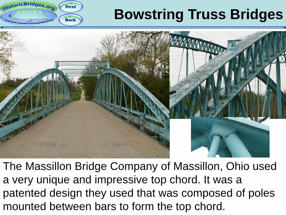
The Massillon Bridge Company of Massillon, Ohio used a very unique and impressive top chord. It was a patented design they used that was composed of poles mounted between bars to form the top chord.
Part 5: Cantilever and Continuous
Truss Bridges
An Introduction To Historic Bridges

Cantilever Truss Bridges
Cantilever truss bridges are a complex, hinged structure type that feature cantilevered arms that extend from a pier to normally hold a structurally independent suspended span at one end, and balance the weight out at the other end extending from the pier.
Suspended Span
Cantilever Arm
Cantilever Arm
Anchor Arm
Anchor Arm
Hinge Points
Cantilever Truss Bridges
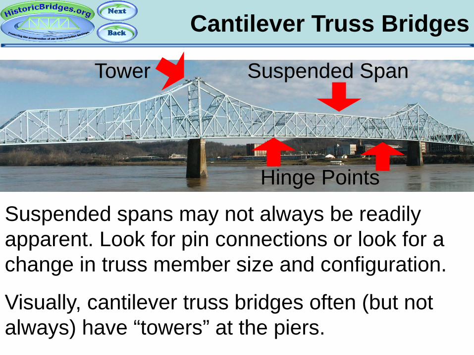
Suspended spans may not always be readily apparent. Look for pin connections or look for a change in truss member size and configuration.
Visually, cantilever truss bridges often (but not always) have “towers” at the piers.
Suspended Span Tower
Hinge Points
Cantilever Truss Bridges
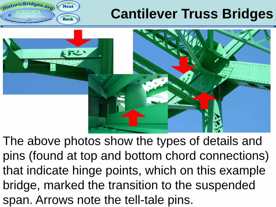
The above photos show the types of details and pins (found at top and bottom chord connections) that indicate hinge points, which on this example bridge, marked the transition to the suspended span. Arrows note the tell-tale pins.
Continuous Truss Bridges
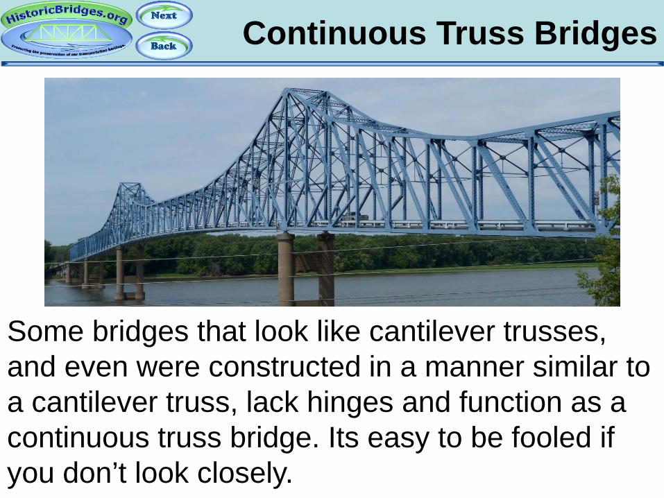
Some bridges that look like cantilever trusses, and even were constructed in a manner similar to a cantilever truss, lack hinges and function as a continuous truss bridge. Its easy to be fooled if you don’t look closely.
Cantilever/Continuous Truss
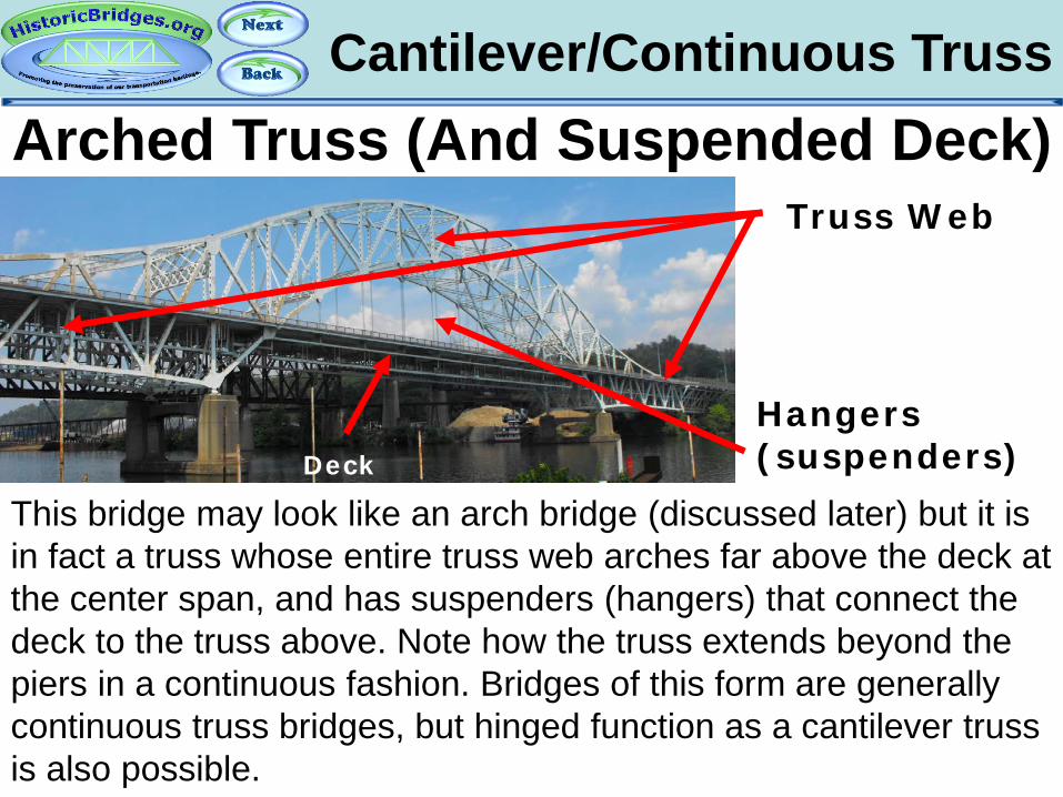
This bridge may look like an arch bridge (discussed later) but it is in fact a truss whose entire truss web arches far above the deck at the center span, and has suspenders (hangers) that connect the deck to the truss above. Note how the truss extends beyond the piers in a continuous fashion. Bridges of this form are generally continuous truss bridges, but hinged function as a cantilever truss is also possible.
Arched Truss (And Suspended Deck) Truss Web
Hangers (suspenders) Deck

Cantilever/Continuous
The design above, often called an “arched truss,” is essentially the same concept as the suspended deck arched truss, except that the truss does not completely rise above the deck, thereby eliminating the need for a suspender/hanger system. Bridges of this form come in both continuous and cantilever configurations.
Arched Truss (No Suspended Deck)

Part 6: Concrete Slab Bridges
An Introduction To Historic Bridges
Concrete Slab Bridges Concrete Slab Bridges
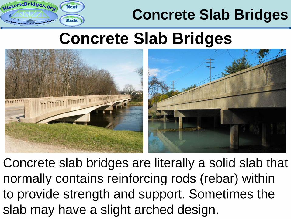
Concrete slab bridges are literally a solid slab that normally contains reinforcing rods (rebar) within to provide strength and support. Sometimes the slab may have a slight arched design.

Part 7: Concrete Rigid-Frame Bridges
An Introduction To Historic Bridges

Rigid-Frame Bridges Concrete Rigid-Frame Bridges
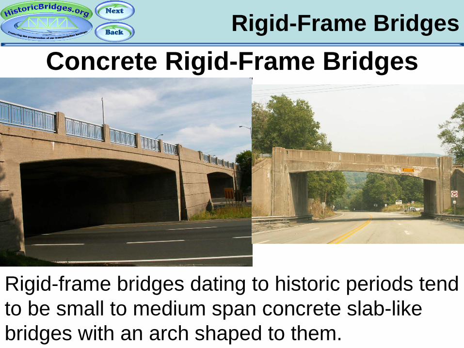
Rigid-frame bridges are concrete bridges where the superstructure and the substructure are cast as one single unit. As such, there are no bearings on rigid-frame bridges.
Rigid-Frame Bridges Concrete Rigid-Frame Bridges
Rigid-frame bridges dating to historic periods tend to be small to medium span concrete slab-like bridges with an arch shaped to them.
Rigid-Frame Bridges Concrete Rigid-Frame Bridges
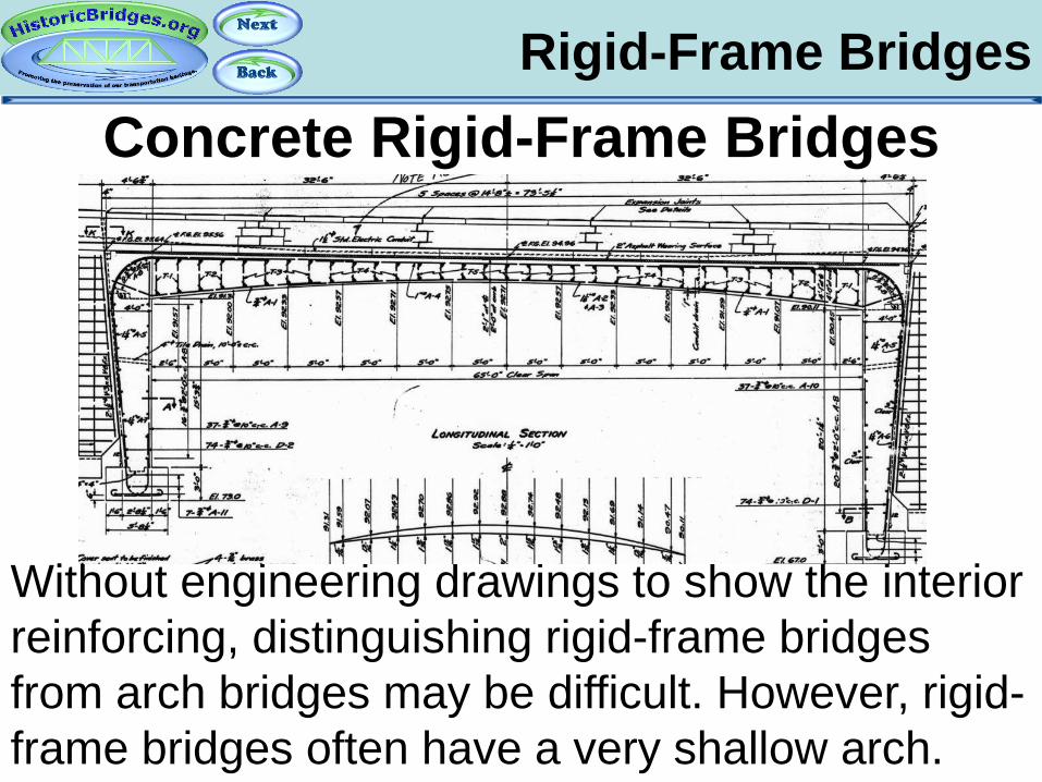
Without engineering drawings to show the interior reinforcing, distinguishing rigid-frame bridges from arch bridges may be difficult. However, rigid-frame bridges often have a very shallow arch.

Part 8: Girder Bridges
An Introduction To Historic Bridges

Girder Bridges Metal Girder Bridges
Metal girder bridges are often called plate girder bridges. The were common on railroads and
some states built them on highways frequently as well. They generally date from 1900 on.
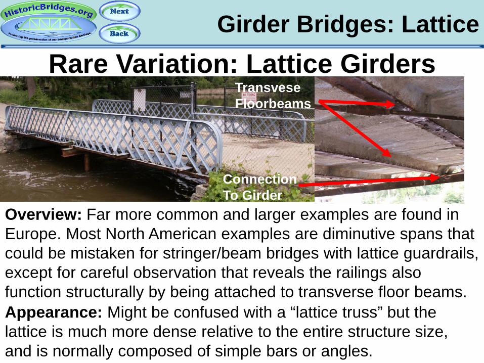
Girder Bridges: Lattice Rare Variation: Lattice Girders
Overview: Far more common and larger examples are found in Europe. Most North American examples are diminutive spans that could be mistaken for stringer/beam bridges with lattice guardrails, except for careful observation that reveals the railings also function structurally by being attached to transverse floor beams. Appearance: Might be confused with a “lattice truss” but the lattice is much more dense relative to the entire structure size, and is normally composed of simple bars or angles.
Transvese Floorbeams
Connection To Girder

Girder Bridges Girder Types
Similar to truss bridges, the girders can be beside the road or below. Typically metal girders do not have
overhead bracing, and those with girders beside the roadway are usually considered through girders.
Deck
Through
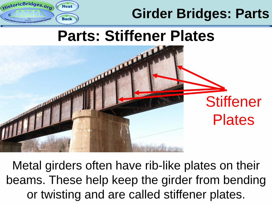
Girder Bridges: Parts Parts: Stiffener Plates
Metal girders often have rib-like plates on their beams. These help keep the girder from bending
or twisting and are called stiffener plates.
Stiffener Plates

Girder Bridges Materials: Concrete
Concrete girder bridges
were also built. They
generally date from 1910
through 1935.
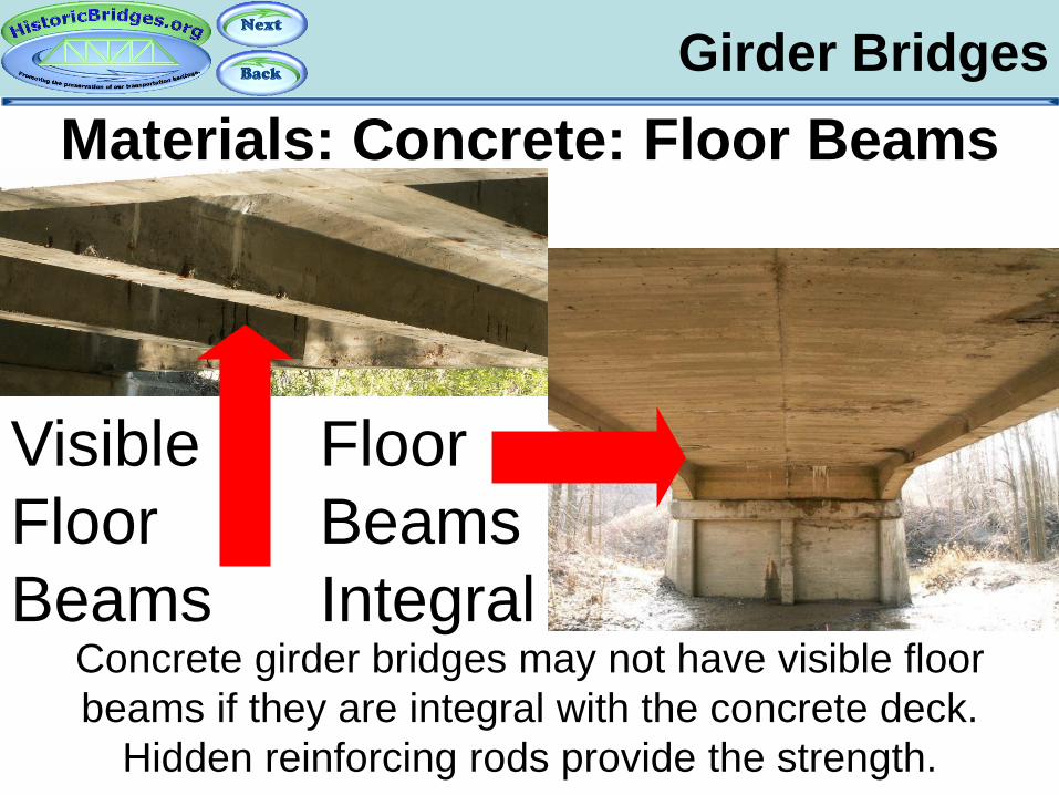
Girder Bridges Materials: Concrete: Floor Beams
Concrete girder bridges may not have visible floor beams if they are integral with the concrete deck.
Hidden reinforcing rods provide the strength.
Visible Floor Beams
Floor Beams Integral
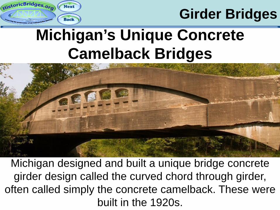
Girder Bridges Michigan’s Unique Concrete
Camelback Bridges
Michigan designed and built a unique bridge concrete girder design called the curved chord through girder,
often called simply the concrete camelback. These were built in the 1920s.
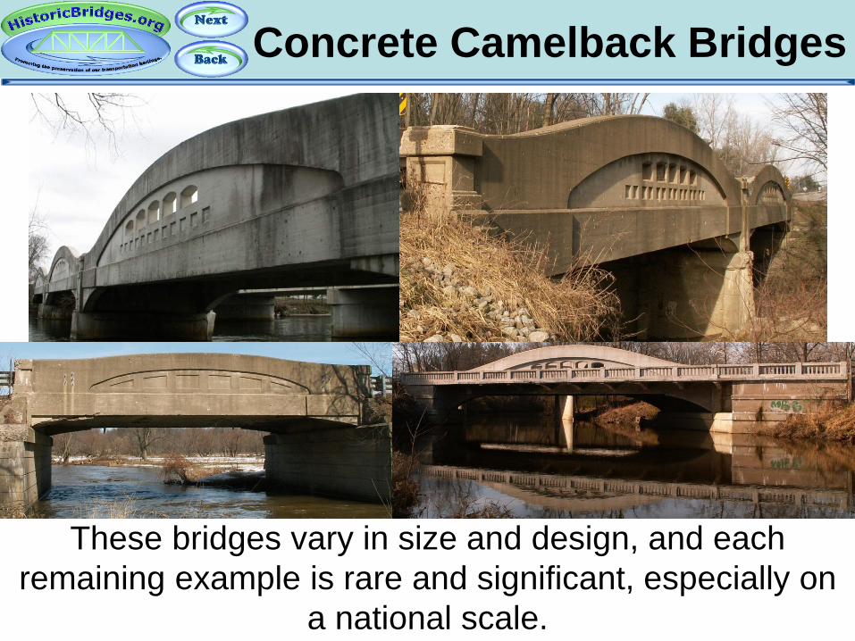
Concrete Camelback Bridges
These bridges vary in size and design, and each remaining example is rare and significant, especially on
a national scale.

Concrete Camelback Bridges
Some other states and provinces had similar designs of this type, but they were never built frequently and few examples remain. Surviving examples should be
considered noteworthy.

Concrete Camelback Bridges HistoricBridges.org has a special webpage
dedicated to discussing the history, design, and significance of Michigan’s Concrete Camelback
Bridges.
historicbridges.org/info/curved/
Part 9: Concrete Arch Bridges
An Introduction To Historic Bridges

Concrete Arch Bridges
Concrete arch bridges were built generally after 1900 and usually are reinforced, with reinforcing rods (rebar)
inside to help hold them together.

Concrete Arch Spandrels
Bridges with visible vertical members, are open spandrel bridges. Those without visible vertical members are closed spandrel bridges.
Open Spandrel Closed Spandrel

Concrete Arch Spandrels
Concrete Arch Bridge Parts. Source: Pennsylvania Department of Transportation
Closed Spandrel Open Spandrel Arch Barrel
Intrados
Extrados

Concrete Arch Spandrels
More Concrete Arch Bridge Terms.
Spring Line
Rise Crown

Closed Spandrel Arches
Closed spandrel arches may have an earthen fill inside.
Earthen Fill Visible With Removed Deck

Rainbow Arch Bridges
Through concrete arch bridges are often called “Rainbow Arch” bridges, and may also be
described as concrete “bowstring arch” bridges. All forms are quite rare.
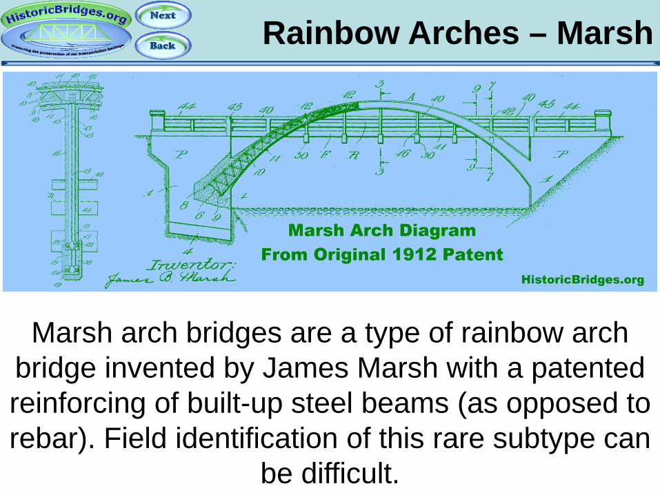
Rainbow Arches – Marsh
Marsh arch bridges are a type of rainbow arch bridge invented by James Marsh with a patented reinforcing of built-up steel beams (as opposed to rebar). Field identification of this rare subtype can
be difficult.

Rainbow Arches – Marsh
Josef Melan was another engineer who developed a solid steel reinforcing for use in concrete arch bridges. In contrast to Marsh
arches, Melan arches are generally deck arch bridges and are also rare. A deteriorated example
above reveals the steel arch reinforcing within.
Exposed Reinforcing

Concrete Arch: Stone Facing
Some concrete arch bridges may have a stone facing that was added to them to make them look
like stone arch bridges. Popular in parks and other developments completed with Federal relief
programs during the Great Depression.

Part 10: Stone Arch Bridges
An Introduction To Historic Bridges

Stone Arch Bridges
Stone arch bridges were generally built in the United States from the 1600s through the 1910s.
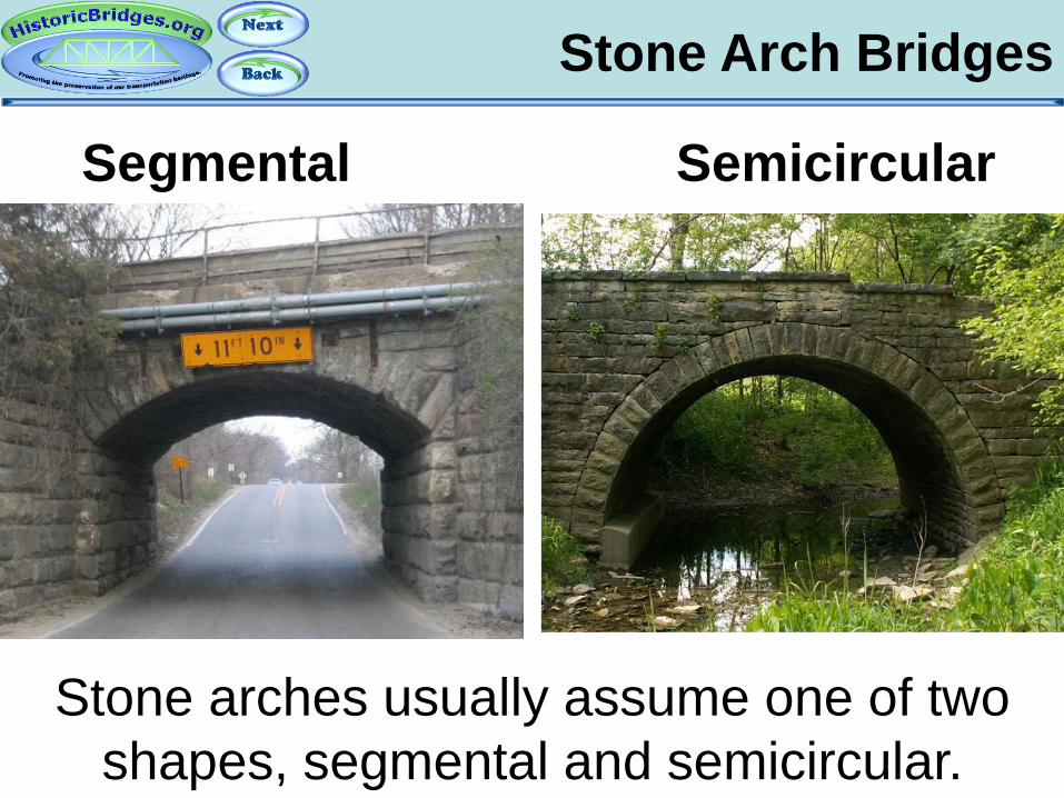
Stone Arch Bridges
Segmental Semicircular
Stone arches usually assume one of two shapes, segmental and semicircular.

Stone Arch Bridges
A third design, elliptical, is extremely rare to find. It features an oblong shape, like a
slightly squashed semicircular arch.
Elliptical
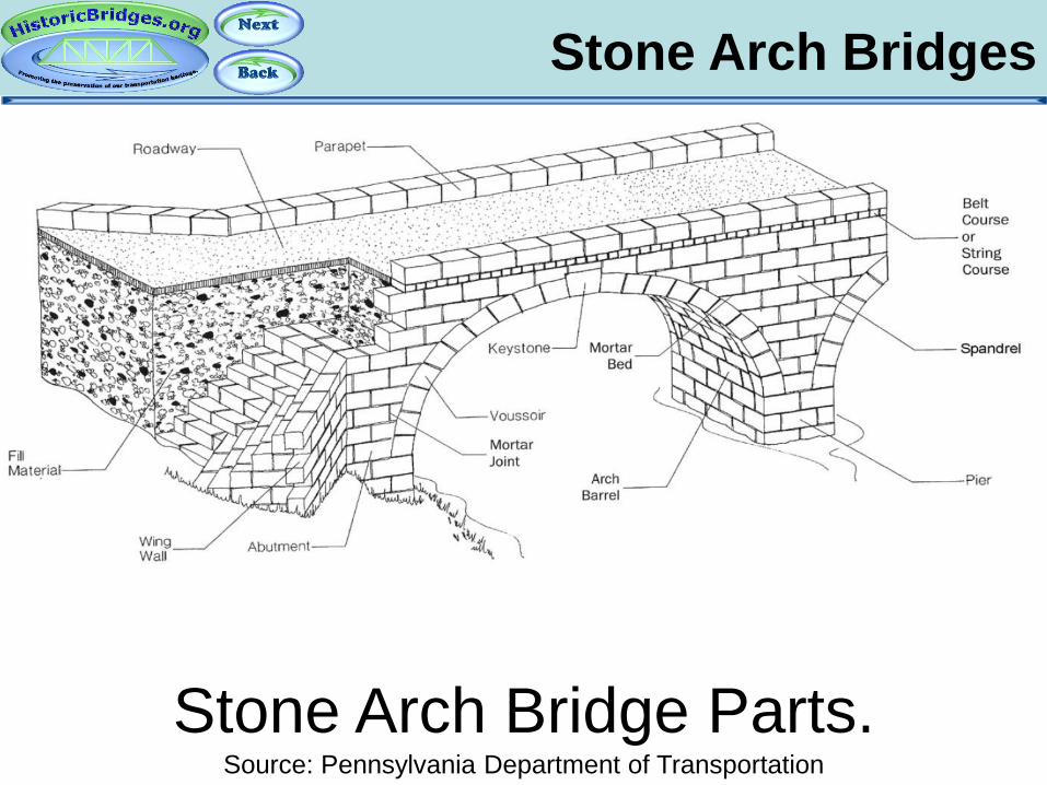
Stone Arch Bridges
Stone Arch Bridge Parts. Source: Pennsylvania Department of Transportation

Stone Arch Bridges
Barrel
Some parts of a stone arch bridge.
Parapet (Railing)
Voussoir
Spandrel Wall
Keystone

Part 11: Metal Arch Bridges
An Introduction To Historic Bridges

Metal Arch Bridges
Metal arch bridges are generally an uncommon structure type. The main structural element, the
arch “rib” may be braced with a truss-like design.
Through Arch With Braced Rib Deck Arch With Solid Rib
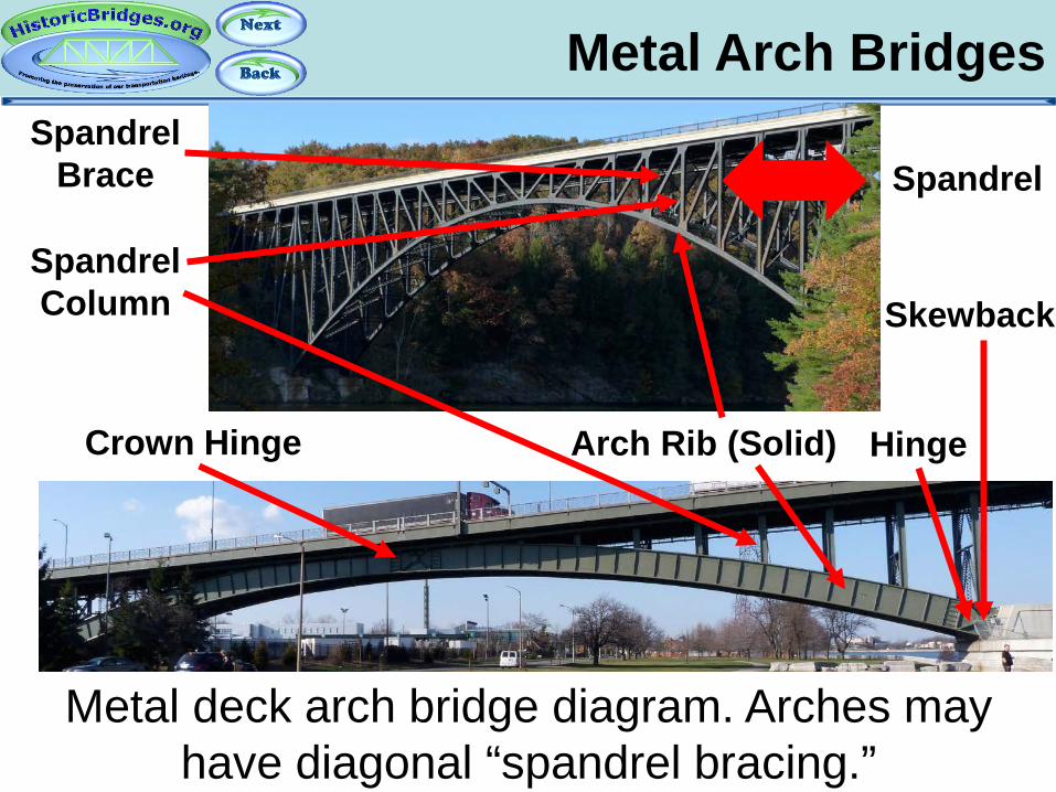
Metal Arch Bridges
Metal deck arch bridge diagram. Arches may have diagonal “spandrel bracing.”
Spandrel Brace
Spandrel Column
Spandrel
Skewback
Arch Rib (Solid) Hinge Crown Hinge

Metal Arch Bridges
In traditional metal arch bridges, the ends of the bridge will thrust their forces into the
piers/abutments at an angle. This angled bearing point at the ends of such arches are called
“skewbacks.”
Arch Rib
Hinge

Metal Arch Bridges
Metal arch bridges may have any number of hinges, from zero to three. Hinges, identified by the presence of a pin can be found at the crown
(center of arch) and/or at the skewbacks. Example hinges shown above.

Metal Arch Bridges
In some cases, hinges on arch bridges were only functional during construction and were made
rigid after the bridge was completed. Example hinges shown above.
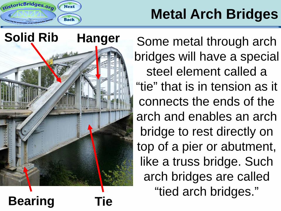
Metal Arch Bridges
Some metal through arch bridges will have a special
steel element called a “tie” that is in tension as it connects the ends of the arch and enables an arch bridge to rest directly on top of a pier or abutment, like a truss bridge. Such arch bridges are called
“tied arch bridges.” Tie Bearing
Solid Rib Hanger

Metal Arch Bridges
In through arch bridges, the deck is suspended from vertical “hangers” which are in tension. In deck arch bridges, the deck rests upon vertical
columns, which are in compression.
Through Arch Hangers
Deck Arch Columns
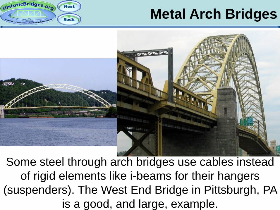
Metal Arch Bridges
Some steel through arch bridges use cables instead of rigid elements like i-beams for their hangers
(suspenders). The West End Bridge in Pittsburgh, PA is a good, and large, example.
Part 12: Stringer Bridges
An Introduction To Historic Bridges
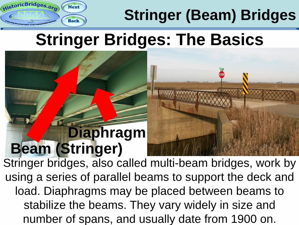
Stringer (Beam) Bridges Stringer Bridges: The Basics
Stringer bridges, also called multi-beam bridges, work by using a series of parallel beams to support the deck and
load. Diaphragms may be placed between beams to stabilize the beams. They vary widely in size and number of spans, and usually date from 1900 on.
Beam (Stringer) Diaphragm

Stringers: Pin And Hanger Stringer Bridges: Pin And Hanger
In a pin-and-hanger stringer bridge, longer stringers extend beyond the piers slightly to act as cantilevers for a shorter suspended stringer span, which is hung from bars connected to the cantilever spans on either side. Note: plate girders can also have pin and hangers.
Suspended Span
Cantilevered Span
Suspended Span
Cantilevered Span

Stringers: Pin And Hanger Stringer Bridges: Pin And Hanger The pin-and hanger
joints allow the bridge to expand and rotate, and
also place the expansion joints away
from the piers, reducing moisture and salt
deterioration of the pier from expansion joint
leakage.
No Deterioration Over Or On Pier
Deterioration From Joint
Leakage
Pin and Hanger

Stringer (Beam) Bridges
Stringer bridges can take on a variety of appearances.

Stringer (Beam) Bridges
Concrete may be used to hide the steel beams, for aesthetic purposes or to protect the beams. Michigan, in particular had a design in late 1920s into the 1930s that
covered the outermost beams with concrete.

Stringer (Beam) Bridges
On old bridges, guardrails were more than just functional, they were decorative. They play a major role
in making old bridges beautiful, especially on simple bridge types like the stringer.
Part 13: T-Beam Bridges
An Introduction To Historic Bridges
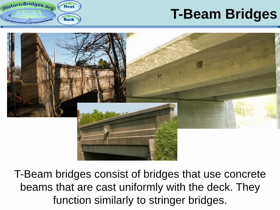
T-Beam Bridges
T-Beam bridges consist of bridges that use concrete beams that are cast uniformly with the deck. They
function similarly to stringer bridges.

T-Beam Bridges Sizes
T-Beam bridges tend to be used on small spans, but in some cases can come in large sizes.
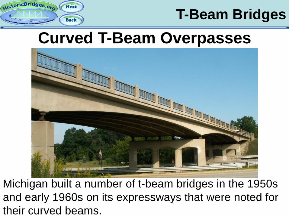
T-Beam Bridges Curved T-Beam Overpasses
Michigan built a number of t-beam bridges in the 1950s and early 1960s on its expressways that were noted for their curved beams.

T-Beam Bridges Curved T-Beam Overpasses
Those that retain their original railings remain a rare example of an expressway bridge that has a high degree of beauty. The arches were also designed for the increase in vertical clearance.

T-Beam Bridges Curved T-Beam Overpasses
This is a heavily skewed example. Note the longer spans and thicker beams.
Part 14: Suspension Bridges
An Introduction To Historic Bridges

Suspension Bridges
Suspension bridges are usually very large landmark bridges. John Roebling made major developments in
the design of these bridges in the 1800s, and this bridge type was further perfected during the 20th
Century.
Suspension Bridges
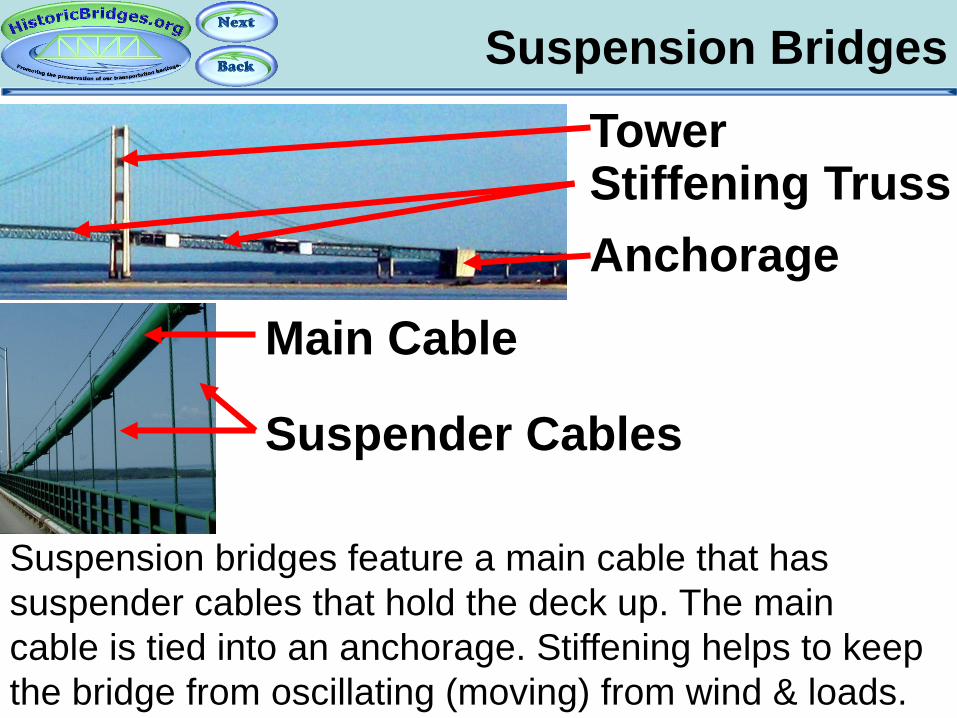
Suspension bridges feature a main cable that has suspender cables that hold the deck up. The main cable is tied into an anchorage. Stiffening helps to keep the bridge from oscillating (moving) from wind & loads.
Tower
Anchorage Stiffening Truss
Main Cable
Suspender Cables
Suspension Bridges
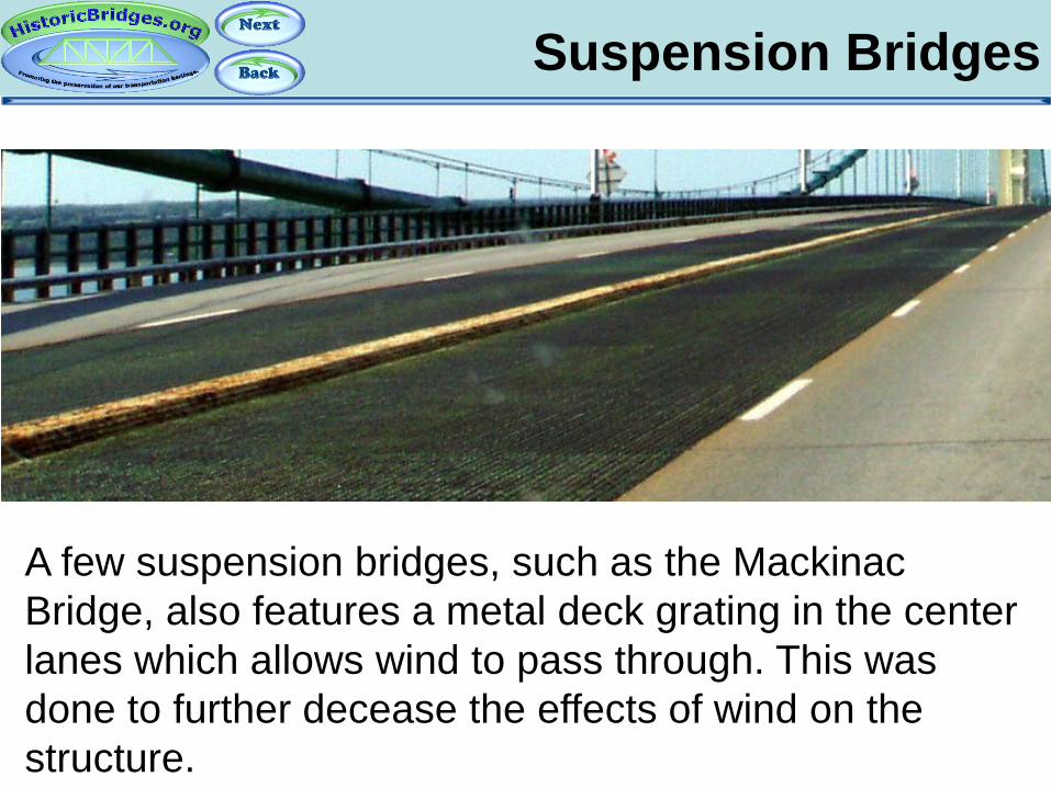
A few suspension bridges, such as the Mackinac Bridge, also features a metal deck grating in the center lanes which allows wind to pass through. This was done to further decease the effects of wind on the structure.
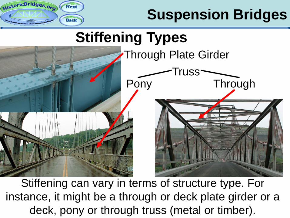
Suspension Bridges
Stiffening can vary in terms of structure type. For instance, it might be a through or deck plate girder or a
deck, pony or through truss (metal or timber).
Stiffening Types Through Plate Girder
Truss Pony Through

Suspension Bridges
A few suspension bridges, such as the “Three Sisters” bridges in Pittsburgh, use eye bars instead of the more
common metal wire cables.

Part 15: Pre-Stressed Concrete Bridges
An Introduction To Historic Bridges

Pre-Stressed Concrete Pre-Stressed Concrete Bridges
Pre-stressed concrete is a type of reinforced concrete that can be used to make concrete slab or concrete multi-beam/stringer bridges. Instead of traditional reinforcing rods, wires are placed in the concrete and “tensioned” or tightened to hold the concrete together.
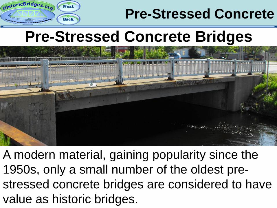
Pre-Stressed Concrete Pre-Stressed Concrete Bridges
A modern material, gaining popularity since the 1950s, only a small number of the oldest pre-stressed concrete bridges are considered to have value as historic bridges.

Part 16: Movable Bridge Types
An Introduction To Historic Bridges
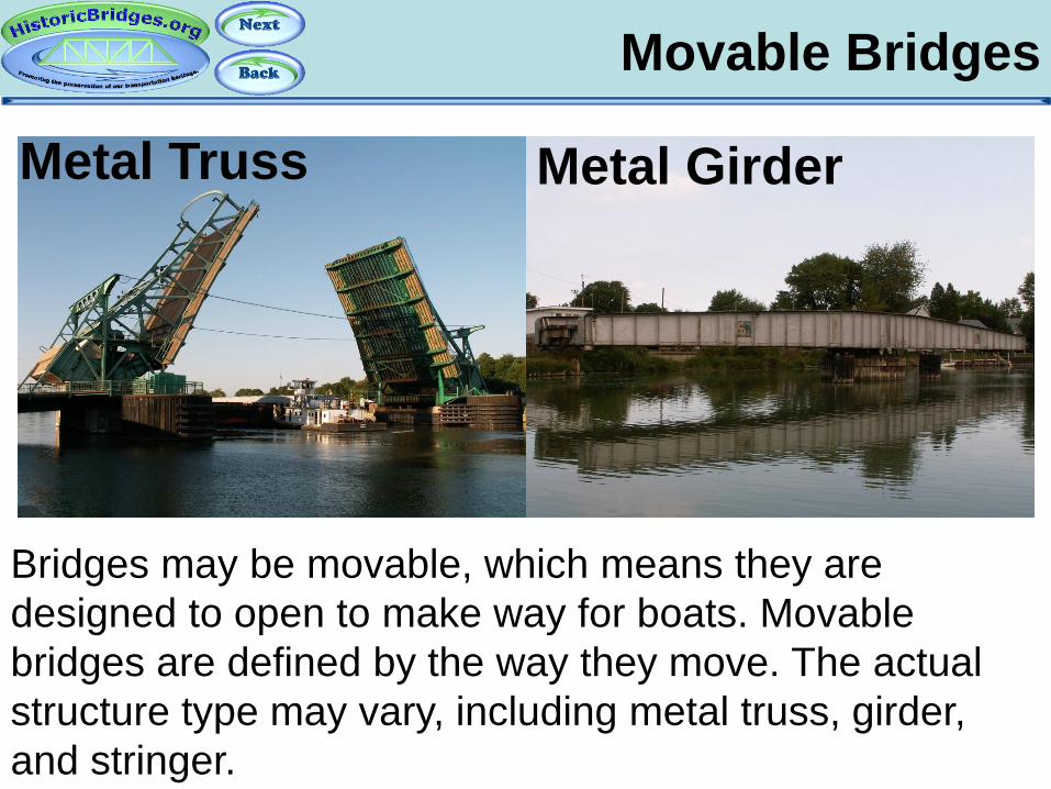
Movable Bridges
Bridges may be movable, which means they are designed to open to make way for boats. Movable bridges are defined by the way they move. The actual structure type may vary, including metal truss, girder, and stringer.
Metal Truss Metal Girder
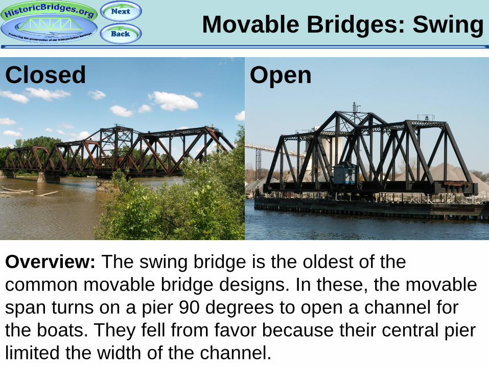
Movable Bridges: Swing
Overview: The swing bridge is the oldest of the common movable bridge designs. In these, the movable span turns on a pier 90 degrees to open a channel for the boats. They fell from favor because their central pier limited the width of the channel.
Closed Open
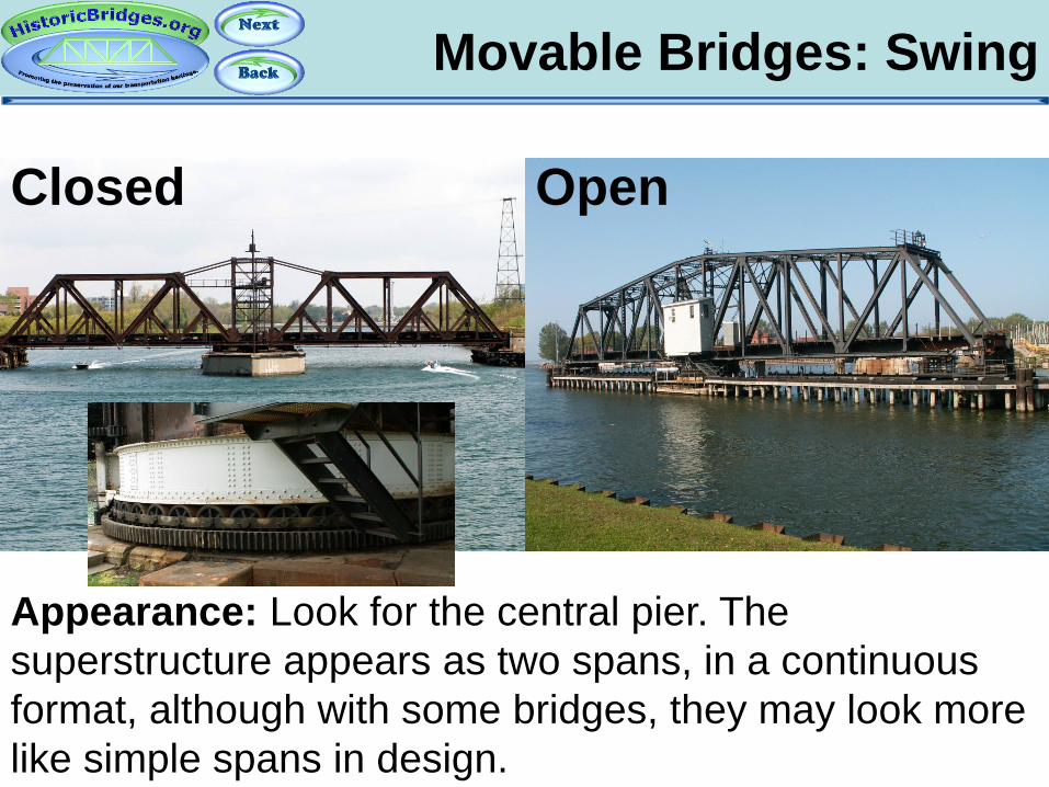
Movable Bridges: Swing
Appearance: Look for the central pier. The superstructure appears as two spans, in a continuous format, although with some bridges, they may look more like simple spans in design.
Closed Open
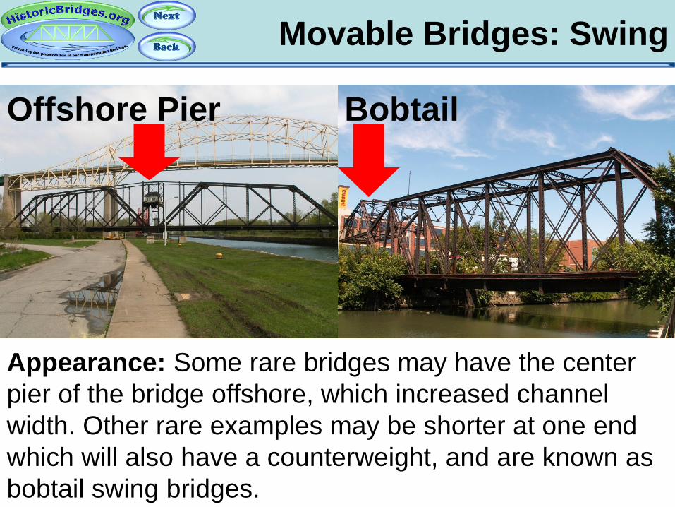
Movable Bridges: Swing
Appearance: Some rare bridges may have the center pier of the bridge offshore, which increased channel width. Other rare examples may be shorter at one end which will also have a counterweight, and are known as bobtail swing bridges.
Offshore Pier Bobtail
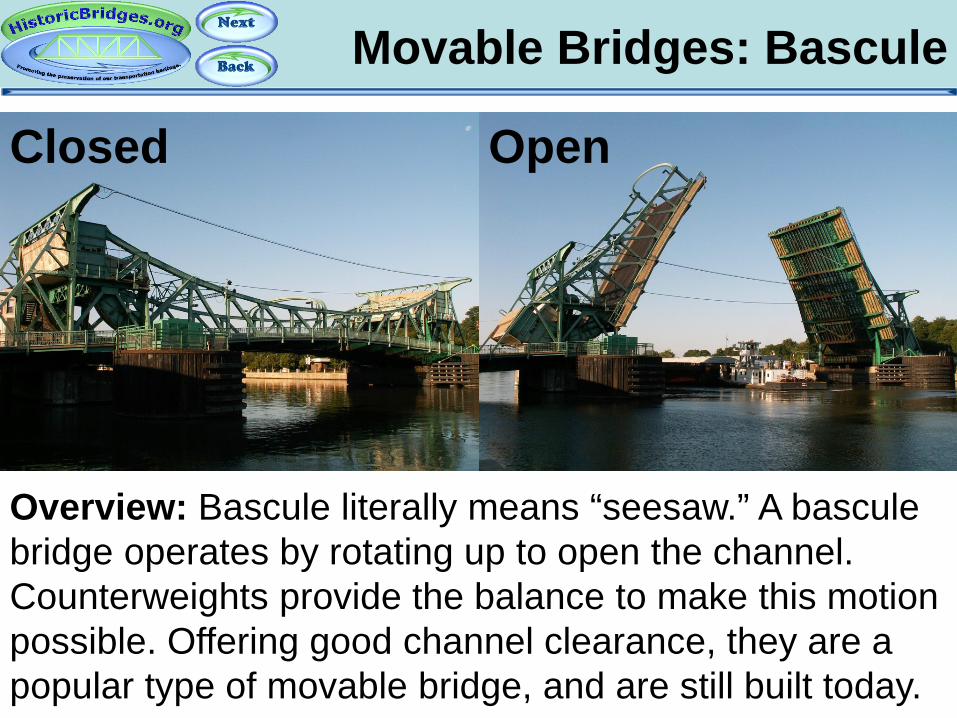
Movable Bridges: Bascule
Overview: Bascule literally means “seesaw.” A bascule bridge operates by rotating up to open the channel. Counterweights provide the balance to make this motion possible. Offering good channel clearance, they are a popular type of movable bridge, and are still built today.
Closed Open
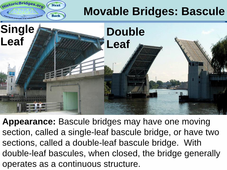
Movable Bridges: Bascule
Appearance: Bascule bridges may have one moving section, called a single-leaf bascule bridge, or have two sections, called a double-leaf bascule bridge. With double-leaf bascules, when closed, the bridge generally operates as a continuous structure.
Single Leaf
Double Leaf

Movable Bridges: Bascule
Appearance: Bascule bridges operate in different ways. There are two common methods of operation. One is to rotate around a trunnion, or large axel, to raise, called a trunnion bascule bridge. Others roll back on a track, and are called rolling lift bascule bridges.
Trunnion Rolling Lift

Movable Bridges: Vertical Lift
Overview: Vertical lift bridges raise the bridge superstructure directly up, to provide the clearance for boats to pass. They can span the entire channel, but are limited in terms of how tall a boat they can service.
Closed Open

Movable Bridges: Vertical Lift
Appearance: Vertical lift bridges feature a single span. Usually, towers will be present at each end. The towers will have counterweights and cables in them to raise the span up.
Closed Open
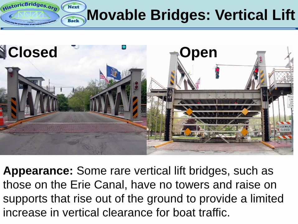
Movable Bridges: Vertical Lift
Appearance: Some rare vertical lift bridges, such as those on the Erie Canal, have no towers and raise on supports that rise out of the ground to provide a limited increase in vertical clearance for boat traffic.
Closed Open

Movable Bridges: Retractile
An extremely rare type of movable bridge, the retractile bridge rolls back away from the navigation channel on rollers.
Part 17: Historic Bridges: A Threatened
Resource
An Introduction To Historic Bridges

A Threatened Resource
Historic Bridges At Risk
Historic bridges are a threatened resource. With the exception of wooden covered bridges, only limited protections and funding exists to preserve them.

A Threatened Resource
Historic Bridges At Risk
As historic bridges age, government agencies seek to replace these bridges with mundane modern structures.
Even if more expensive, it is generally easier for agencies to secure funding for replacement rather than
rehabilitation.

A Threatened Resource
Historic Bridges At Risk
Historic bridges are currently being demolished at an alarming rate. If legislators are not convinced to expand protection and funding for historic bridges, it may soon
be too late to save the best bridges.
A Threatened Resource
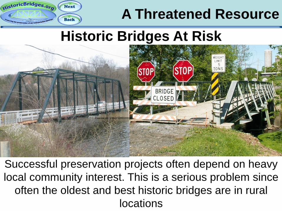
Historic Bridges At Risk
Successful preservation projects often depend on heavy local community interest. This is a serious problem since
often the oldest and best historic bridges are in rural locations
A Threatened Resource
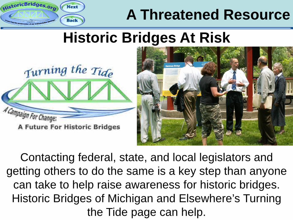
Historic Bridges At Risk
Contacting federal, state, and local legislators and getting others to do the same is a key step than anyone
can take to help raise awareness for historic bridges. Historic Bridges of Michigan and Elsewhere’s Turning
the Tide page can help.
A Threatened Resource
Historic Bridges At Risk
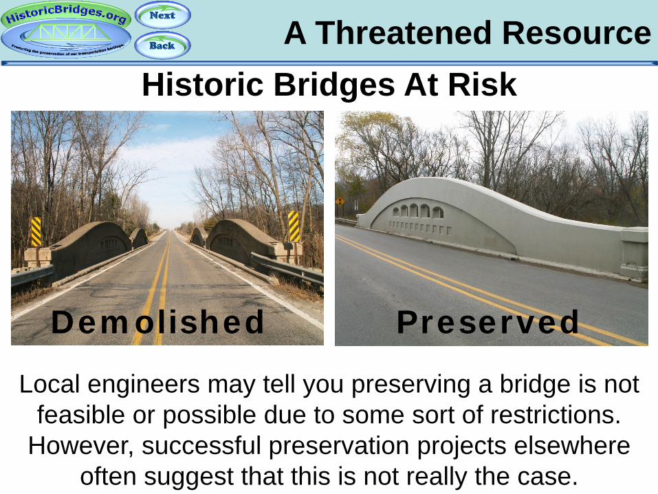
Local engineers may tell you preserving a bridge is not feasible or possible due to some sort of restrictions.
However, successful preservation projects elsewhere often suggest that this is not really the case.
Demolished Preserved
Part 18: Conclusions
An Introduction To Historic Bridges

Wooden Covered Bridges
Covered bridges have been sensationalized by the media and by tourism organizations, even if they are not original or historic. Government programs fund covered bridges, while demolishing other types. HistoricBridges.org seeks to raise awareness of the rest of the fascinating historic bridge world, which has been being demolished for far too long.
But What About Wooden Covered Bridges?!

Wooden Covered Bridges
Travel agents, published books, government and personal websites, and even organized covered bridge groups all can help you plan a covered bridge tour should you wish to take one.
Currently however, only historic bridge websites like HistoricBridges.org, and similar websites on the Internet offer you the vast, rich world beyond covered bridges.

Visit The Website
HistoricBridges.org is a key to the world of historic bridges. Informative narratives provide you with history, news, and technical facts for each bridge. Maps allow you to plan a historic bridge trip. Thousands of photos are offered, including large-size photos for printing or
use as computer wallpaper.

Visit The Website
Enjoy the world of historic bridges. Take a trip, either far away or in your own county and see what it offers!
Be sure to let your lawmakers and government officials know that historic bridge preservation is important to
you.

The Historic Bridge World
This presentation has been a sampling of the world of historic bridges. It is a seemingly endless world of variety and exploration, yet at the same time it is a
limited world, endangered by the continuing demolition of countless historic bridges.
Related Documents