An Intermedia Synchronization Mechanism for Multimedia Distributed Systems S.E. Pomares Hernandez*, J. Estudillo Ramirez, L.A. Morales Rosales and G. Rodriguez Gomez Computer Science Department, National Institute of Astrophysics, Optics and Electronics (INAOE), Mexico E-mail:{spomares, jestudillo, lamorales, grodrig}inaoep.mx *Corresponding author Abstract: Emerging distributed multimedia systems such as Telemedicine, Tele- Conference and IPTV, deal with simultaneous geographically distributed sources by transmitting heterogeneous data, such as text, images, graphics, video and audio. The preservation of temporal relations that consider different data types and simultaneous distributed sources is an open research area. Although several works try to specify and execute at runtime distributed temporal multimedia scenarios, they are far from resolving the problem. This paper proposes a synchronization mechanism to be used at runtime in distributed multimedia systems. One original aspect of the present work is that we avoid the use of a common reference by executing all possible multimedia temporal relations according to their causal dependencies. We emulate the mechanism considering a wide area network environment and using MPEG-4 encoders. The emulation results show that our mechanism is effective in reducing the intermedia synchronization error that can exist. The present work does not require previous knowledge of when, nor for how long, the media involved of a temporal scenario is executed. Keywords: Multimedia Distributed Systems, Temporal Synchronization, Causal Ordering Reference Biographical notes: Saul Eduardo Pomares Hernandez is a Researcher in the Computer Science Department at the National Institute of Astrophysics, Optics and Electronics, in Puebla, Mexico. He completed his PhD degree at the Laboratory for Analysis and Architecture of Systems of CNRS, France in 2002. Since 1998, he has been researching in the field of distributed systems, partial order algorithms and multimedia synchronization.

Welcome message from author
This document is posted to help you gain knowledge. Please leave a comment to let me know what you think about it! Share it to your friends and learn new things together.
Transcript

An IntermediaSynchronization Mechanismfor Multimedia DistributedSystems
S.E. Pomares Hernandez*,J. Estudillo Ramirez,L.A. Morales Rosales andG. Rodriguez GomezComputer Science Department,National Institute of Astrophysics, Optics and Electronics (INAOE), MexicoE-mail:{spomares, jestudillo, lamorales, grodrig}inaoep.mx*Corresponding author
Abstract: Emerging distributed multimedia systems such as Telemedicine, Tele-Conference and IPTV, deal with simultaneous geographically distributed sources bytransmitting heterogeneous data, such as text, images, graphics, video and audio. Thepreservation of temporal relations that consider different data types and simultaneousdistributed sources is an open research area. Although several works try to specifyand execute at runtime distributed temporal multimedia scenarios, they are far fromresolving the problem. This paper proposes a synchronization mechanism to be usedat runtime in distributed multimedia systems. One original aspect of the present workis that we avoid the use of a common reference by executing all possible multimediatemporal relations according to their causal dependencies. We emulate the mechanismconsidering a wide area network environment and using MPEG-4 encoders. Theemulation results show that our mechanism is effective in reducing the intermediasynchronization error that can exist. The present work does not require previousknowledge of when, nor for how long, the media involved of a temporal scenario isexecuted.
Keywords: Multimedia Distributed Systems, Temporal Synchronization, CausalOrdering
Reference
Biographical notes: Saul Eduardo Pomares Hernandez is a Researcher in theComputer Science Department at the National Institute of Astrophysics, Optics andElectronics, in Puebla, Mexico. He completed his PhD degree at the Laboratoryfor Analysis and Architecture of Systems of CNRS, France in 2002. Since 1998, hehas been researching in the field of distributed systems, partial order algorithms andmultimedia synchronization.
1 INTRODUCTION
Multimedia systems deal with heterogeneous data, such astext, graphics, images, audio, video and animations. Gen-erally, multimedia data is grouped into two types: con-tinuous media (e.g. audio and video) and discrete media(e.g. text, data and images) (Geyer et al., 1996). Themain difference between these two types is that while con-tinuous media events are considered to be executed duringa period of time, discrete media events are considered tobe executed at specific timeless points. One open researcharea in distributed multimedia systems involves interme-dia synchronization. Intermedia synchronization concernsthe preservation of temporal dependencies among the ap-plication data from the time of generation to the time ofpresentation. For example, in a one-to-many synchronoustelemedicine session, a specialist exposes to a group of col-leagues his diagnosis, which was obtained from the medicalimages of a patient (e.g. radiography, magnetic resonanceand tomography). In this case, the specialist sends medicalimages (discrete media) through a teleradiology tool andhe makes use of two continuous medias (audio and video)to give comments about them. The intermedia synchro-nization, in this scenario, must ensure that at any recep-tion participant (Client) (see Figure 1), the images mustbe presented according to the phrases pronounced with itscorresponding video. A simple on-site meeting situationsuch as “We distinguish in the next tomography...” (associ-ated with the correspondent concurrent presentation imageaction) is not simple to reproduce on a telemedicine ses-sion since the communication channels are asynchronousand independent, and the media involved is heterogeneous(Balaouras et al., 2000). The term next in the scenario es-tablishes, at an application level, a temporal dependencywith the remaining media involved. In such case, if tempo-ral dependencies are not ensured, it is possible that a re-ceiver can associate, without distinction, this phrase withthe current, the preceding or the following medical im-age. Satisfying temporal dependencies is even more com-plex for cooperative many-to-many multimedia scenarios,where geographically distributed participants simultane-ously communicate. The present work mainly focuses onthis last kind of scenarios, where in principle there are noglobal references, such as a wall clock or a shared memory.
Several works attempt to give a possible solution to theintermedia synchronization in distributed systems (Bulter-man D., 2008; Geyer et al., 1996; Ishibashi et al., 1999;Plesca et al., 2005; Shimamura et al., 2001); however, aswe will see in the related work section, these works arefar from resolving the problem. In this paper, we pro-pose an intermedia synchronization mechanism based onthe logical mapping concept presented by Morales Ros-ales and Pomares Hernandez (2006). We use the log-ical mapping to specify, according to causal dependen-cies, any kind of temporal relationship among the mul-timedia data involved: continuous-continuous, discrete-
Copyright c© 200x Inderscience Enterprises Ltd.
� �
Audio
Teleradiology tool
Video
Client
U
V
u− u+
v− v+
m1 m2
u− v−m1 u+
δ1 δ2 · · ·time
δ1 δ2 · · · δt
Figure 1: A telemedicine multimedia scenario example
discrete, and discrete-continuous relations. Our mecha-nism takes as base the specification obtained by the logi-cal mapping in order to establish “when”a multimedia datamust be delivered, and consequently, executed by a partic-ipant.
We emulate the mechanism considering some wide net-work conditions and using MPEG-4 encoders (Mackieet al., 2000). We note that even when the audio and videoare considered to be continuous, their transmission usingMPEG-4 (and similar encoders) is in fact non-continuoussince compression techniques, such as silence compressionand remotion of temporal redundancy, are used. We showin this paper how our mechanism takes into considerationthis behavior and is able to reduce the intermedia synchro-nization error without needing to use previous knowledgeof the system nor global references.
This paper is structured as follows. Section 2 presentsthe most relevant related work. Next, in Section 3, the sys-tem model is described, and the background informationis provided. In Section 4, the temporal model concerningdiscrete and continuous media is presented. The synchro-nization mechanism with a detailed description is shown inSection 5. The emulation results are presented in Section6. Finally, some conclusions are given in Section 7.
2 RELATED WORK
Many works related to multimedia synchronization ex-ist. We classify them according to the mode of execu-tion, namely: offline mode and inline mode. The offlinemode refers to when the specification of a temporal sce-nario is manually made and previous to the media datatransmision. The most representative works in this cate-gory are: the object composition Petri net model (OCPN)introduced by Little and Ghafoor (1990), the timing andsynchronization model of SMIL (Bulterman D., 2008), andthe time ontology model of OWL (Bechhofer S., 2006). Themain characteristic of the works in this category is thatthey need complete previous knowledge of the media data,the temporal dependencies and/or the actions sequence or-der, before carrying out the temporal specification.
On the other hand, we have the inline mode. In this
2
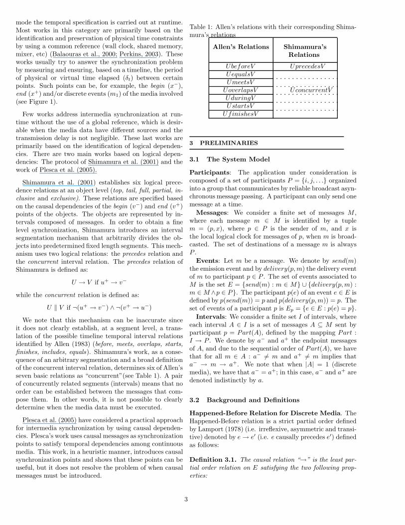
mode the temporal specification is carried out at runtime.Most works in this category are primarily based on theidentification and preservation of physical time constraintsby using a common reference (wall clock, shared memory,mixer, etc) (Balaouras et al., 2000; Perkins, 2003). Theseworks usually try to answer the synchronization problemby measuring and ensuring, based on a timeline, the periodof physical or virtual time elapsed (δt) between certainpoints. Such points can be, for example, the begin (x−),end (x+) and/or discrete events (m1) of the media involved(see Figure 1).
Few works address intermedia synchronization at run-time without the use of a global reference, which is desir-able when the media data have different sources and thetransmission delay is not negligible. These last works areprimarily based on the identification of logical dependen-cies. There are two main works based on logical depen-dencies: The protocol of Shimamura et al. (2001) and thework of Plesca et al. (2005).
Shimamura et al. (2001) establishes six logical prece-dence relations at an object level (top, tail, full, partial, in-clusive and exclusive). These relations are specified basedon the causal dependencies of the begin (v−) and end (v+)points of the objects. The objects are represented by in-tervals composed of messages. In order to obtain a finelevel synchronization, Shimamura introduces an intervalsegmentation mechanism that arbitrarily divides the ob-jects into predetermined fixed length segments. This mech-anism uses two logical relations: the precedes relation andthe concurrent interval relation. The precedes relation ofShimamura is defined as:
U → V if u+ → v−
while the concurrent relation is defined as:
U ‖ V if ¬(u+ → v−) ∧ ¬(v+ → u−)
We note that this mechanism can be inaccurate sinceit does not clearly establish, at a segment level, a trans-lation of the possible timeline temporal interval relationsidentified by Allen (1983) (before, meets, overlaps, starts,finishes, includes, equals). Shimamura’s work, as a conse-quence of an arbitrary segmentation and a broad definitionof the concurrent interval relation, determines six of Allen’sseven basic relations as “concurrent”(see Table 1). A pairof concurrently related segments (intervals) means that noorder can be established between the messages that com-pose them. In other words, it is not possible to clearlydetermine when the media data must be executed.
Plesca et al. (2005) have considered a practical approachfor intermedia synchronization by using causal dependen-cies. Plesca’s work uses causal messages as synchronizationpoints to satisfy temporal dependencies among continuousmedia. This work, in a heuristic manner, introduces causalsynchronization points and shows that these points can beuseful, but it does not resolve the problem of when causalmessages must be introduced.
Table 1: Allen’s relations with their corresponding Shima-mura’s relations
Allen’s Relations Shimamura’sRelations
UbeforeV UprecedesVUequalsVUmeetsV
UoverlapsV UconcurrentVUduringVUstartsV
UfinishesV
3 PRELIMINARIES
3.1 The System Model
Participants: The application under consideration iscomposed of a set of participants P = {i, j, . . .} organizedinto a group that communicates by reliable broadcast asyn-chronous message passing. A participant can only send onemessage at a time.
Messages: We consider a finite set of messages M ,where each message m ∈ M is identified by a tuplem = (p, x), where p ∈ P is the sender of m, and x isthe local logical clock for messages of p, when m is broad-casted. The set of destinations of a message m is alwaysP .
Events: Let m be a message. We denote by send(m)the emission event and by delivery(p, m) the delivery eventof m to participant p ∈ P . The set of events associated toM is the set E = {send(m) : m ∈ M} ∪ {delivery(p, m) :m ∈M ∧p ∈ P}. The participant p(e) of an event e ∈ E isdefined by p(send(m)) = p and p(delivery(p, m)) = p. Theset of events of a participant p is Ep = {e ∈ E : p(e) = p}.
Intervals: We consider a finite set I of intervals, whereeach interval A ∈ I is a set of messages A ⊆ M sent byparticipant p = Part(A), defined by the mapping Part :I → P . We denote by a− and a+ the endpoint messagesof A, and due to the sequential order of Part(A), we havethat for all m ∈ A : a− �= m and a+ �= m implies thata− → m → a+. We note that when |A| = 1 (discretemedia), we have that a− = a+; in this case, a− and a+ aredenoted indistinctly by a.
3.2 Background and Definitions
Happened-Before Relation for Discrete Media. TheHappened-Before relation is a strict partial order definedby Lamport (1978) (i.e. irreflexive, asymmetric and transi-tive) denoted by e→ e′ (i.e. e causally precedes e′) definedas follows:
Definition 3.1. The causal relation “→” is the least par-tial order relation on E satisfying the two following prop-erties:
3
1. For each participant p, the set of events Ep involvingp is totally ordered: e, e′ ∈ Ep ⇒ e→ e′ ∨ e′ → e
2. For each message m and destination p ∈ P of m, theemission of m precedes its delivery; i.e. send(m) →delivery(p, m)
By using “→”, Lamport defines that two events are con-current as follows:
e ‖ e′ if ¬(e→ e′ ∨ e′ → e)A behavior or a set of behaviors satisfies causal order de-
livery if the diffusion of a message m causally precedes thediffusion of a message m′, and the delivery of m causallyprecedes the delivery of m′ for all participants that belongto P . Formally, we have:
Definition 3.2. Causal Order Delivery (broadcast case):If send(m) → send(m′), then ∀p ∈ P : delivery(p, m) →delivery(p, m′)
Partial Causal Relation (PCR). The PCR relationwas introduced by Fanchon et al. (2004) (Definition 3.2). Itconsiders a subset M ′ ⊆M of messages. The PCR inducedby M ′ takes into account the subset of events E′ ⊆ E thatrefer to send or delivery events of the messages belongingto M ′. In our work, the PCR relation is a non strict partialorder (i.e. reflexive, asymmetric, and transitive).
Definition 3.3. The partial causal relation “→E′” is theleast partial order relation satisfying the two followingproperties:
1. For each participant p ∈ P , the local restrictions of→E′ and → to the events of E′
p coincide: ∀e, e′ ∈ E′p :
e→ e′ ⇔ e→E′ e′
2. For each message m ∈ M ′and j ∈ P , the emission ofm precedes its delivery to j : j ∈ P ⇒ send(m) →E′
delivery(j, m)
Happened-Before Relation for Intervals. Lamport(1986) establishes that an interval A happens before an-other interval B if all elements that compose interval Acausally precede all elements of interval B. This definitionis used in the model presented in Section 4. However, ac-cording to the specification of Intervals presented in Sec-tion 3.1, the causal interval relation “→I”can be expressedonly in terms of the endpoints as follows:
Property 3.4. The relation “→I” is accomplished if thetwo following conditions are satisfied:
1. A→I B if a+ →E′ b−
2. A→I B if ∃C | (a+ →E′ c− ∧ c+ →E′ b−)
where a+ and b− are the endpoints of A and B, respec-tively, c− and c+ are the endpoints of C, and →E′ is thepartial causal order (Definition 3.2) induced on E′ ⊆ E,where E′, in this case, is the subset composed by the end-point events of the intervals in I. When |A| = 1, we havethat a− = a+ = a; and in this case, we consider a→ a.
Next, we present the simultaneous relation for intervals,defined as follows:
Definition 3.5. Two intervals, A and B, are said to besimultaneous “|||” if the following condition is satisfied:
A ||| B ⇒ a− ‖ b− ∧ a+ ‖ b+
The definition above means that one interval A can takeplace at the “same time”as another interval B.
Finally, we present the definition of causal delivery forintervals based on their endpoints as follows:
Definition 3.6. Causal Broadcast Delivery for IntervalsIf (a+, b−) ∈ A×B, send(a+)→E′ send(b−)⇒∀p ∈ P, delivery(p, a+)→E′ delivery(p, b−), then∀p ∈ P, delivery(p, A)→I delivery(p, B)
4 THE LOGICAL MAPPING MODEL
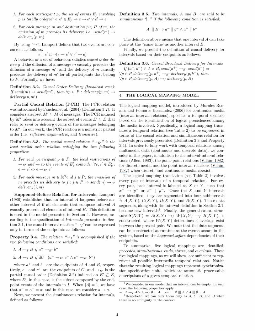
The logical mapping model, introduced by Morales Ros-ales and Pomares Hernandez (2006) for continuous media(interval-interval relations), specifies a temporal scenariobased on the identification of logical precedences amongthe media involved. Specifically, a logical mapping trans-lates a temporal relation (see Table 2) to be expressed interms of the causal relation and simultaneous relation forintervals previously presented (Definition 3.3 and Property3.4). In order to fully work with temporal relations amongmultimedia data (continuous and discrete data), we con-sider in this paper, in addition to the interval-interval rela-tions (Allen, 1983), the point-point relations (Vilain, 1982)for discrete media and the point-interval relations (Vilain,1982) when discrete and continuous media coexist.
The logical mapping translation (see Table 2) involvesevery pair of intervals of a temporal relation. For ev-ery pair, each interval is labeled as X or Y , such thatx− → y− or x− ‖ y−. Once the X and Y intervalsare identified, they are segmented into four subintervals1: A(X, Y ), C(X, Y ), D(X, Y ), and B(X, Y ). These datasegments, along with the interval definition in Section 3.1,become new intervals2. Finally, the general causal struc-ture S(X, Y ) = A(X, Y ) →I W (X, Y ) →I B(X, Y ), isconstructed, where W (X, Y ) determines if overlaps existbetween the present pair. We note that the data segmentscan be constructed at runtime as the events occurs in thesystem, based on the happened-before dependencies of theirendpoints.
To summarize, five logical mappings are identified:precedes, simultaneous, ends, starts, and overlaps. Thesefive logical mappings, as we will show, are sufficient to rep-resent all possible intermedia temporal relations. Noticethat the resulting logical mappings represent synchroniza-tion specification units, which are automatic processabledescriptions of a given temporal relation.
1We consider in our model that an interval can be empty. In suchcase, the following properties apply:− ∅ →I A ∨ A →I ∅ = A and ∅ ||| A ∨ A ||| ∅ = A
2Henceforth, we can refer them only as A, C, D, and B whenthere is no ambiguity in the context
4
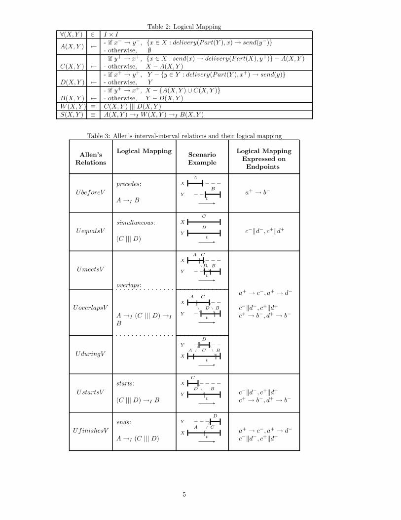
Table 2: Logical Mapping∀(X, Y ) ∈ I × I
A(X, Y ) ← - if x− → y−, {x ∈ X : delivery(Part(Y ), x)→ send(y−)}- otherwise, ∅
C(X, Y ) ←- if y+ → x+, {x ∈ X : send(x)→ delivery(Part(X), y+)} −A(X, Y )- otherwise, X −A(X, Y )
D(X, Y ) ←- if x+ → y+, Y − {y ∈ Y : delivery(Part(Y ), x+)→ send(y)}- otherwise, Y
B(X, Y ) ←- if y+ → x+, X − {A(X, Y ) ∪ C(X, Y )}- otherwise, Y −D(X, Y )
W (X, Y ) ≡ C(X, Y ) ||| D(X, Y )S(X, Y ) ≡ A(X, Y )→I W (X, Y )→I B(X, Y )
Table 3: Allen’s interval-interval relations and their logical mapping
Allen’sRelations
Logical Mapping ScenarioExample
Logical MappingExpressed onEndpoints
precedes : X
Y
A
B
tUbeforeV a+ → b−
A→I B
simultaneous: X
Y
C
D
tUequalsV c−‖d−, c+‖d+
(C ||| D)
X
Y
|
|
A C
D B
tUmeetsV
overlaps :
X
Y
|
|
A C
D B
t
a+ → c−, a+ → d−
UoverlapsV c−‖d−, c+‖d+
A →I (C ||| D) →I
Bc+ → b−, d+ → b−
Y
X | |A
D
C B
tUduringV
starts : X
Y |
C
D B
tUstartsV c−‖d−, c+‖d+
(C ||| D)→I B c+ → b−, d+ → b−
ends : Y
X |
D
CA
tUfinishesV a+ → c−, a+ → d−
A→I (C ||| D) c−‖d−, c+‖d+
5
We will now present the establishment of the logi-cal mappings for point-point and point-continuous rela-tions. The interval-interval relations have been presentedby Morales Rosales and Pomares Hernandez (2006) (seeTable 3).
4.0.1 Logical Mapping for Discrete Media
Vilain establishes three possible basic point-point tempo-ral relations based on a timeline, which are before (<),simultaneous (=) and after (>) (See Table 4 left column).After applying Table 2 to each possible temporal relation,we identify two logical mappings, which are precedes andsimultaneous (See Table 4, right column). We can see thatthese logical mappings are the same as defined at an in-terval level for the continuous media. They differ in therepresentation endpoints. For example, when x < y (beforerelation), we have A = {x} and B = {y}, and therefore,we obtain the logical mapping A →I B. We have for thislogical mapping an endpoint representation a→ b.
Table 4: Vilain’s point-point relations and their logicalmapping
BasicPoint
Relations
LogicalMapping
Logical MappingExpressed onEndpoints
x < y precedes :a→ b
y > x A→I B
x = ysimultaneous:
c ‖ dC ||| D
4.0.2 Logical Mapping for Discrete and Continu-ous Media
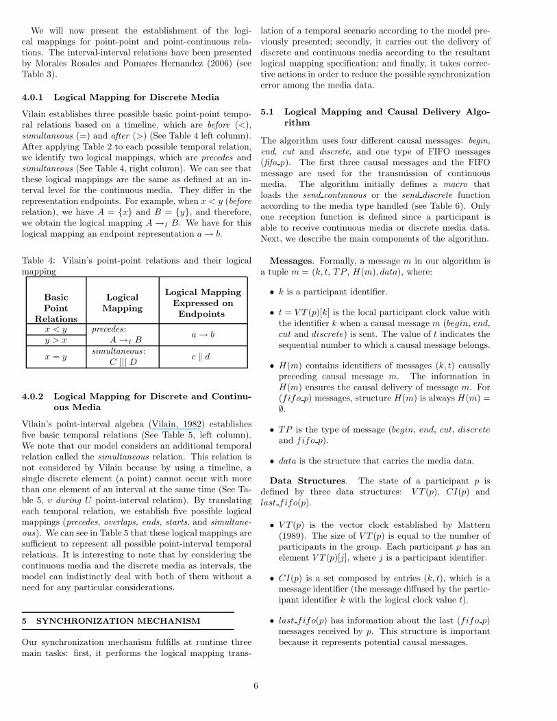
Vilain’s point-interval algebra (Vilain, 1982) establishesfive basic temporal relations (See Table 5, left column).We note that our model considers an additional temporalrelation called the simultaneous relation. This relation isnot considered by Vilain because by using a timeline, asingle discrete element (a point) cannot occur with morethan one element of an interval at the same time (See Ta-ble 5, v during U point-interval relation). By translatingeach temporal relation, we establish five possible logicalmappings (precedes, overlaps, ends, starts, and simultane-ous). We can see in Table 5 that these logical mappings aresufficient to represent all possible point-interval temporalrelations. It is interesting to note that by considering thecontinuous media and the discrete media as intervals, themodel can indistinctly deal with both of them without aneed for any particular considerations.
5 SYNCHRONIZATION MECHANISM
Our synchronization mechanism fulfills at runtime threemain tasks: first, it performs the logical mapping trans-
lation of a temporal scenario according to the model pre-viously presented; secondly, it carries out the delivery ofdiscrete and continuous media according to the resultantlogical mapping specification; and finally, it takes correc-tive actions in order to reduce the possible synchronizationerror among the media data.
5.1 Logical Mapping and Causal Delivery Algo-rithm
The algorithm uses four different causal messages: begin,end, cut and discrete, and one type of FIFO messages(fifo p). The first three causal messages and the FIFOmessage are used for the transmission of continuousmedia. The algorithm initially defines a macro thatloads the send continuous or the send discrete functionaccording to the media type handled (see Table 6). Onlyone reception function is defined since a participant isable to receive continuous media or discrete media data.Next, we describe the main components of the algorithm.
Messages. Formally, a message m in our algorithm isa tuple m = (k, t, TP , H(m), data), where:
• k is a participant identifier.
• t = V T (p)[k] is the local participant clock value withthe identifier k when a causal message m (begin, end,cut and discrete) is sent. The value of t indicates thesequential number to which a causal message belongs.
• H(m) contains identifiers of messages (k, t) causallypreceding causal message m. The information inH(m) ensures the causal delivery of message m. For(fifo p) messages, structure H(m) is always H(m) =∅.
• TP is the type of message (begin, end, cut, discreteand fifo p).
• data is the structure that carries the media data.
Data Structures. The state of a participant p isdefined by three data structures: V T (p), CI(p) andlast fifo(p).
• V T (p) is the vector clock established by Mattern(1989). The size of V T (p) is equal to the number ofparticipants in the group. Each participant p has anelement V T (p)[j], where j is a participant identifier.
• CI(p) is a set composed by entries (k, t), which is amessage identifier (the message diffused by the partic-ipant identifier k with the logical clock value t).
• last fifo(p) has information about the last (fifo p)messages received by p. This structure is importantbecause it represents potential causal messages.
6
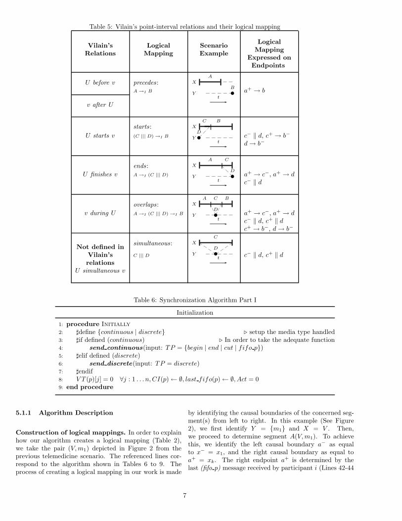
Table 5: Vilain’s point-interval relations and their logical mapping
Vilain’sRelations
LogicalMapping
ScenarioExample
LogicalMapping
Expressed onEndpoints
U before v precedes : X
Y
A
B
t
A →I B a+ → b
v after U
starts : X
Y
|D
C B
tU starts v (C ||| D) →I B c− ‖ d, c+ → b−
d→ b−
ends : X
Y
|D
CA
tU finishes v A →I (C ||| D) a+ → c−, a+ → d
c− ‖ d
overlaps : X
Y
| |A BC
D
tv during U A →I (C ||| D) →I B a+ → c−, a+ → d
c− ‖ d, c+ ‖ dc+ → b−, d→ b−
Not defined in simultaneous: X
Y
C
D
tVilain’srelations
C ||| D c− ‖ d, c+ ‖ d
U simultaneous v
Table 6: Synchronization Algorithm Part I
Initialization
1: procedure Initially
2: �define {continuous | discrete} � setup the media type handled3: �if defined (continuous) � In order to take the adequate function4: send continuous(input: TP = {begin | end | cut | fifo p})5: �elif defined (discrete)6: send discrete(input: TP = discrete)7: �endif8: V T (p)[j] = 0 ∀j : 1 . . . n, CI(p)← ∅, last fifo(p)← ∅, Act = 09: end procedure
5.1.1 Algorithm Description
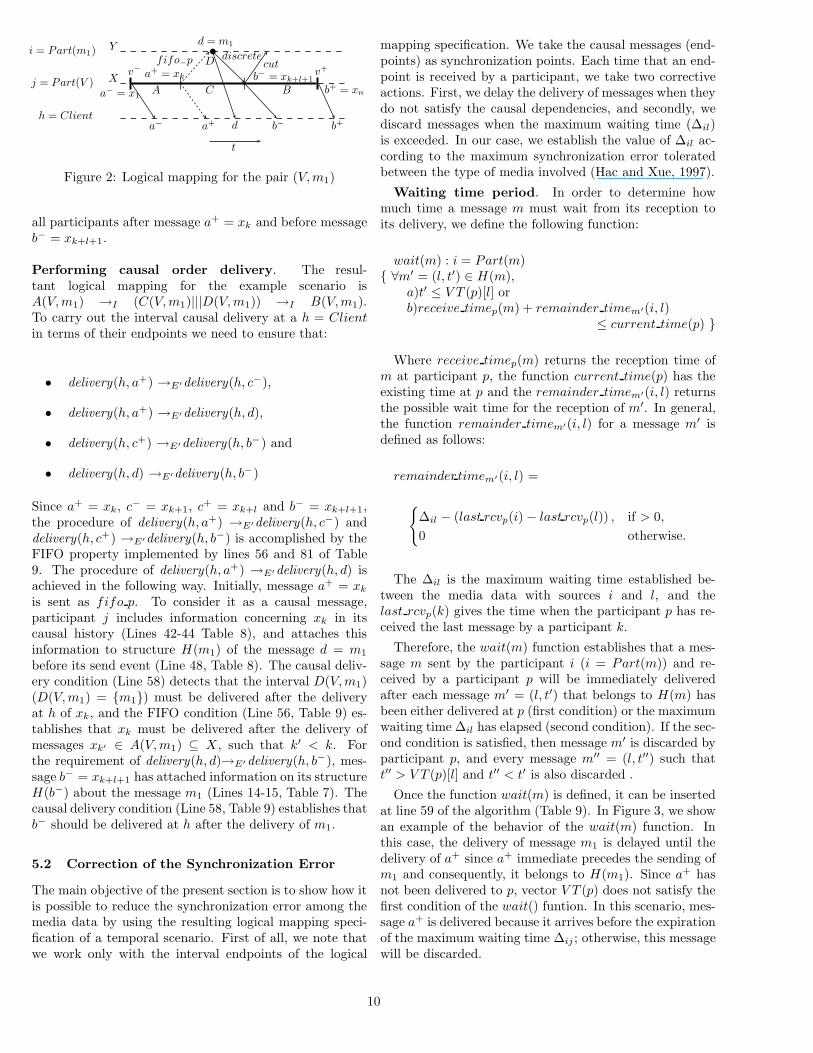
Construction of logical mappings. In order to explainhow our algorithm creates a logical mapping (Table 2),we take the pair (V, m1) depicted in Figure 2 from theprevious telemedicine scenario. The referenced lines cor-respond to the algorithm shown in Tables 6 to 9. Theprocess of creating a logical mapping in our work is made
by identifying the causal boundaries of the concerned seg-ment(s) from left to right. In this example (See Figure2), we first identify Y = {m1} and X = V . Then,we proceed to determine segment A(V, m1). To achievethis, we identify the left causal boundary a− as equalto x− = x1, and the right causal boundary as equal toa+ = xk. The right endpoint a+ is determined by thelast (fifo p) message received by participant i (Lines 42-44
7
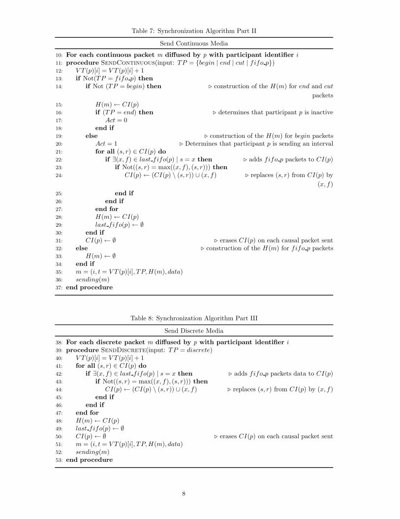
Table 7: Synchronization Algorithm Part II
Send Continuous Media
10: For each continuous packet m diffused by p with participant identifier i11: procedure SendContinuous(input: TP = {begin | end | cut | fifo p})12: V T (p)[i] = V T (p)[i] + 113: if Not(TP = fifo p) then14: if Not (TP = begin) then � construction of the H(m) for end and cut
packets15: H(m)← CI(p)16: if (TP = end) then � determines that participant p is inactive17: Act = 018: end if19: else � construction of the H(m) for begin packets20: Act = 1 � Determines that participant p is sending an interval21: for all (s, r) ∈ CI(p) do22: if ∃(x, f) ∈ last fifo(p) | s = x then � adds fifo p packets to CI(p)23: if Not((s, r) = max((x, f), (s, r))) then24: CI(p)← (CI(p) \ (s, r)) ∪ (x, f) � replaces (s, r) from CI(p) by
(x, f)25: end if26: end if27: end for28: H(m)← CI(p)29: last fifo(p)← ∅30: end if31: CI(p)← ∅ � erases CI(p) on each causal packet sent32: else � construction of the H(m) for fifo p packets33: H(m)← ∅34: end if35: m = (i, t = V T (p)[i], TP, H(m), data)36: sending(m)37: end procedure
Table 8: Synchronization Algorithm Part III
Send Discrete Media
38: For each discrete packet m diffused by p with participant identifier i39: procedure SendDiscrete(input: TP = discrete)40: V T (p)[i] = V T (p)[i] + 141: for all (s, r) ∈ CI(p) do42: if ∃(x, f) ∈ last fifo(p) | s = x then � adds fifo p packets data to CI(p)43: if Not((s, r) = max((x, f), (s, r))) then44: CI(p)← (CI(p) \ (s, r)) ∪ (x, f) � replaces (s, r) from CI(p) by (x, f)45: end if46: end if47: end for48: H(m)← CI(p)49: last fifo(p)← ∅50: CI(p)← ∅ � erases CI(p) on each causal packet sent51: m = (i, t = V T (p)[i], TP, H(m), data)52: sending(m)53: end procedure
8
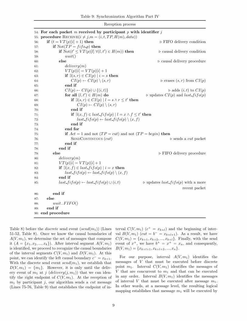
Table 9: Synchronization Algorithm Part IV
Reception process
54: For each packet m received by participant p with identifier j55: procedure Receive(i �= j,m = (i, t, TP, H(m), data))56: if (t = V T (p)[i] + 1) then � FIFO delivery condition57: if Not(TP = fifo p) then58: if Not(t′ ≤ V T (p)[l] ∀(l, t′) ∈ H(m)) then � causal delivery condition59: wait()60: else � causal delivery procedure61: delivery(m)62: V T (p)[i] = V T (p)[i] + 163: if ∃(s, r) ∈ CI(p) | i = s then64: CI(p)← CI(p) \ (s, r) � erases (s, r) from CI(p)65: end if66: CI(p)← CI(p) ∪ {(i, t)} � adds (i, t) to CI(p)67: for all (l, t′) ∈ H(m) do � updates CI(p) and last fifo(p)68: if ∃(s, r) ∈ CI(p) | l = s ∧ r ≤ t′ then69: CI(p)← CI(p) \ (s, r)70: end if71: if ∃(x, f) ∈ last fifo(p) | l = x ∧ f ≤ t′ then72: last fifo(p)← last fifo(p) \ (x, f)73: end if74: end for75: if Act = 1 and not (TP = cut) and not (TP = begin) then76: SENDCONTINUOUS (cut) � sends a cut packet77: end if78: end if79: else � FIFO delivery procedure80: delivery(m)81: V T (p)[i] = V T (p)[i] + 182: if ∃(x, f) ∈ last fifo(p) | i = x then83: last fifo(p)← last fifo(p) \ (x, f)84: end if85: last fifo(p)← last fifo(p) ∪ (i, t) � updates last fifo(p) with a more
recent packet86: end if87: else88: wait−FIFO()89: end if90: end procedure
Table 8) before the discrete send event (send(m1)) (Lines51-52, Table 8). Once we know the causal boundaries ofA(V, m1), we determine the set of messages that composeit (A = {x1, x2, ..., xk}). After interval segment A(V, m1)is identified, we proceed to recognize the causal boundariesof the interval segments C(V, m1) and D(V, m1). At thispoint, we can identify the left causal boundary c− = xk+1.With the discrete send event send(m1), we establish thatD(V, m1) = {m1}. However, it is only until the deliv-ery event of m1 at j (delivery(j, m1)) that we can iden-tify the right endpoint of C(V, m1). At the reception ofm1 by participant j, our algorithm sends a cut message(Lines 75-76, Table 9) that establishes the endpoint of in-
terval C(V, m1) (c+ = xk+l) and the beginning of inter-val B(V, m1) (cut = b− = xk+l+1). As a result, we haveC(V, m1) = {xk+1, xk+2, ..., xk+l}. Finally, with the sendevent of x+, we have b+ = x+ = xn, and consequently,B(V, m1) = {xk+l+1, xk+l+2, ..., xn}.
For our purpose, interval A(V, m1) identifies themessages of V that must be executed before discretepoint m1. Interval C(V, m1) identifies the messages ofV that are concurrent to m1 and that can be executedin any order. Interval B(V, m1) identifies the messagesof interval V that must be executed after message m1.In other words, at a message level, the resulting logicalmapping establishes that message m1 will be executed by
9
�
t
d = m1
v−i = Part(m1)
j = Part(V )
h = Client
A C B
Dv+
Y
X
a− = x1
a+ = xk b− = xk+l+1
b+ = xn
fifo−p discretecut
a− a+ d b− b+
Figure 2: Logical mapping for the pair (V, m1)
all participants after message a+ = xk and before messageb− = xk+l+1.
Performing causal order delivery. The resul-tant logical mapping for the example scenario isA(V, m1) →I (C(V, m1)|||D(V, m1)) →I B(V, m1).To carry out the interval causal delivery at a h = Clientin terms of their endpoints we need to ensure that:
• delivery(h, a+) →E′delivery(h, c−),
• delivery(h, a+) →E′delivery(h, d),
• delivery(h, c+) →E′delivery(h, b−) and
• delivery(h, d) →E′delivery(h, b−)
Since a+ = xk, c− = xk+1, c+ = xk+l and b− = xk+l+1,the procedure of delivery(h, a+) →E′delivery(h, c−) anddelivery(h, c+) →E′delivery(h, b−) is accomplished by theFIFO property implemented by lines 56 and 81 of Table9. The procedure of delivery(h, a+) →E′delivery(h, d) isachieved in the following way. Initially, message a+ = xk
is sent as fifo p. To consider it as a causal message,participant j includes information concerning xk in itscausal history (Lines 42-44 Table 8), and attaches thisinformation to structure H(m1) of the message d = m1
before its send event (Line 48, Table 8). The causal deliv-ery condition (Line 58) detects that the interval D(V, m1)(D(V, m1) = {m1}) must be delivered after the deliveryat h of xk, and the FIFO condition (Line 56, Table 9) es-tablishes that xk must be delivered after the delivery ofmessages xk′ ∈ A(V, m1) ⊆ X , such that k′ < k. Forthe requirement of delivery(h, d)→E′delivery(h, b−), mes-sage b− = xk+l+1 has attached information on its structureH(b−) about the message m1 (Lines 14-15, Table 7). Thecausal delivery condition (Line 58, Table 9) establishes thatb− should be delivered at h after the delivery of m1.
5.2 Correction of the Synchronization Error
The main objective of the present section is to show how itis possible to reduce the synchronization error among themedia data by using the resulting logical mapping speci-fication of a temporal scenario. First of all, we note thatwe work only with the interval endpoints of the logical
mapping specification. We take the causal messages (end-points) as synchronization points. Each time that an end-point is received by a participant, we take two correctiveactions. First, we delay the delivery of messages when theydo not satisfy the causal dependencies, and secondly, wediscard messages when the maximum waiting time (Δil)is exceeded. In our case, we establish the value of Δil ac-cording to the maximum synchronization error toleratedbetween the type of media involved (Hac and Xue, 1997).
Waiting time period. In order to determine howmuch time a message m must wait from its reception toits delivery, we define the following function:
wait(m) : i = Part(m){ ∀m′ = (l, t′) ∈ H(m),
a)t′ ≤ V T (p)[l] orb)receive timep(m) + remainder timem′(i, l)
≤ current time(p) }
Where receive timep(m) returns the reception time ofm at participant p, the function current time(p) has theexisting time at p and the remainder timem′(i, l) returnsthe possible wait time for the reception of m′. In general,the function remainder timem′(i, l) for a message m′ isdefined as follows:
remaindertimem′(i, l) =
{Δil − (last rcvp(i)− last rcvp(l)) , if > 0,
0 otherwise.
The Δil is the maximum waiting time established be-tween the media data with sources i and l, and thelast rcvp(k) gives the time when the participant p has re-ceived the last message by a participant k.
Therefore, the wait(m) function establishes that a mes-sage m sent by the participant i (i = Part(m)) and re-ceived by a participant p will be immediately deliveredafter each message m′ = (l, t′) that belongs to H(m) hasbeen either delivered at p (first condition) or the maximumwaiting time Δil has elapsed (second condition). If the sec-ond condition is satisfied, then message m′ is discarded byparticipant p, and every message m′′ = (l, t′′) such thatt′′ > V T (p)[l] and t′′ < t′ is also discarded .
Once the function wait(m) is defined, it can be insertedat line 59 of the algorithm (Table 9). In Figure 3, we showan example of the behavior of the wait(m) function. Inthis case, the delivery of message m1 is delayed until thedelivery of a+ since a+ immediate precedes the sending ofm1 and consequently, it belongs to H(m1). Since a+ hasnot been delivered to p, vector V T (p) does not satisfy thefirst condition of the wait() funtion. In this scenario, mes-sage a+ is delivered because it arrives before the expirationof the maximum waiting time Δij ; otherwise, this messagewill be discarded.
10

�
t
d = m1
v−
j = Part(m1)
i = Part(V )
Client
A C B
Dv+
remainder−timea+(i, j)
a+b−
d b−a+
Figure 3: Example of synchronization error correction
5.3 Measuring the Synchronization Error
In order to evaluate the impact of the synchronizationmechanism proposed in this paper, we define two equa-tions, the rcv synch errorp(m) and dlv synch errorp(m).The function rcv synch errorp(m) estimates the synchro-nization error by p at the reception of a causal messagem, and dlv synch errorp(m) estimates the synchroniza-tion error at the moment of the delivery of m, which ismeasured after applying the correction mechanism.
The rcv synch errorp(m) is defined as follows:
rcv synch errorp(m) =∑(l,t′)∈H(m) receive timep(m)− last rcvp(l)
|H(m)| (1)
The dlv synch errorp(m) is defined as follows:
dlv synch errorp(m) =∑(l,t′)∈H(m) delivery timep(m)− last dlvp(l)
|H(m)| (2)
Where delivery timep(m) returns the delivery time ofm at participant p, and last dlvp(l) gives the time whenparticipant p has delivered the last message saw from par-ticipant l.
6 EMULATION RESULTS
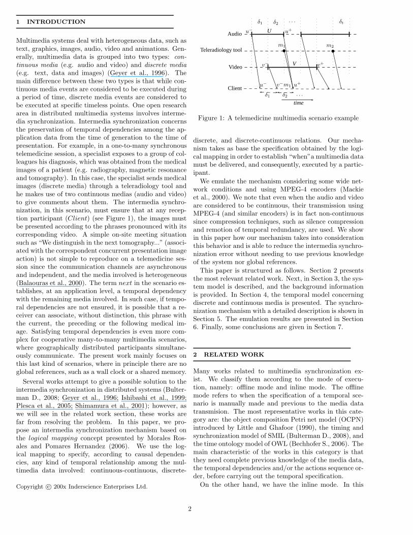
We have tested our synchronization mechanism consider-ing some WAN network characteristics such as transmis-sion delay and partial order delivery. To emulate a WANnetwork behavior, we use the NIST Net emulation tool(Carson and Santay, 2003). In order emphasize the poten-tial situation of unphased media data, we construct an em-ulation environment, see Figure 4, that consists of a groupof four distributed hosts, three of them transmitting livemultimedia data, while the other functions only as Client(Host Z). Each host has two input and one output com-munication channels. The sending hosts only transmit onemedia (audio, video or images), see Figure 4. For the au-dio and video, we use MPEG-4 encoders of the MPEG4IPproject (Mackie et al., 2000). For the case of audio, thesilence compression MPEG-4 CELP mode is used. In thismode, we send a begin message each time that the TX Flag
Host Z
Host W Host X Host Y
WAN
AudioVideoImage
Figure 4: Emulation architecture
equals to 1 (indicates voice activity), and a frame is sendas an end message each time that TX Flag �= 1 (indicatesno or low voice activity). For the remaining audio frames,we send them as fifo p messages. For the case of video,the video was encoded as a single video object into a singlevideo object layer with a rate of 25 frames/s, the group ofpictures (GoP) pattern is set to IBBPBBPBBPBB. The Iframes are sent as begin messages, and the last B framesof the patterns are send as end messages. The rest ofthe video frames are sent as fifo p messages. To emulatethe sending of images we randomly generate and trans-mit discrete events, approximately each 1200 ms based ona random variable with normal distribution. These dataare sent as discrete messages. In this scenario, each hosthas the synchronization mechanism running and only theClient measures the synchronization error by using equa-tions 1 and 2. For simplicity, we consider only one maxi-mum waiting time for every pair of media data Δ = 240ms,which is the maximum synchronization error establishedfor image-audio in real time in Hac and Xue (1997).
With this configuration, we present two tests; one withoptimal conditions, which means that the transmissiondelay considered among the media data does not surpassthe synchronization error tolerate; while in the other,the transmission delay can be greater than the thesynchronization error, resulting in not accomplishing ofthe required QoS. The traffic conditions are presented inTable 10.
Test 1. Under optimal conditions, we can see inFigure 5 that the estimated error at the reception timeremains acceptable; nevertheless, our mechanism, at themoment of the media delivery, reduces the synchronizationerror that in this case is close to zero during almost theentire transmission.
Test 2. For the second test, we can see in Figure 6that at the reception time, the synchronization errorsurpasses in several points the maximum error tolerated.This effect can produce, at application level, the loss ofcoherency among the media played. In this case, afterapplying our mechanism, the error is decreased, making itacceptable in nearly all cases.
11

Table 10: Transmission delay established for emulationData Type Source Target Test 1
(ms)Test 2(ms)
Video/Audio Host X/Y Host Z 300± 120 300± 180Still images Host W Host Z 200± 50 200± 100
−40
0
40
80
120
160
200
240
280
320
360
400
440
0 1 2 3 4 5 6 7 8 9 10 11 12 13 14 15 16 17 18
Time (ms× 1000)
Sync
hron
izat
ion
erro
r(m
s)
�� �� �� �� �� �� ��
��
�� �� �� �� �� �� ��
��
�� �� �� �� ��
��
�� �� ��
��
��
��
��
�� ��
��
��
��
����
��
�� ��
����
��
Synchronization error at reception time��
Synchronization error at delivery time��
Max allowed error (QoS)
Figure 5: Test 1 graphics results: Audio and video (300±120 ms); Still Images (200± 50 ms)
−400
4080
120160200240280320360400440480520560600
0 1 2 3 4 5 6 7 8 9 10 11 12 13 14 15 16 17 18
Time (ms× 1000)
Sync
hron
izat
ion
erro
r(m
s)
�� ��
��
��
�� ����
�� ��
�� ��
��
��
��
��
�� ��
����
�� �� ��
��
��
��
��
��
����
��
��
��
��
��
��
��
��
��
��
��
��
���� ��
Synchronization error at reception time��
Synchronization error at delivery time��
Max allowed error (QoS)
Figure 6: Test 2 graphics results: Audio and video (300±180 ms); Image (200± 100 ms)
7 CONCLUSIONS
We have presented an intermedia synchronization mech-anism that mainly focuses on distributed multimediadata. The mechanism addresses the problem of satisfy-ing any temporal dependencies for continuous-continuous,discrete-continuous, and discrete-discrete relations. Itscore is the use of logical mappings, which specify tempo-ral relations without using global references based on thecausal dependencies of the media involved. In order tobe efficient, the proposed mechanism uses the specification
of logical mappings based on the endpoints. In our work,these endpoints are sent as causal messages which deter-mine synchronization points for any reception process. Todemonstrate the viability and effectiveness of the synchro-nization mechanism, we carry out the emulation of themechanism considering some aspects of a WAN networkenvironment and using MPEG-4 encoders. The emulationresults show the benefits of our mechanism by reducing inall cases the synchronization error of the system.
We note that further work is needed in order to considermore network and media conditions, such as loss of mes-sages and intra-stream lifetime constraints. Our attentionis focused in this direction, and we expect to have someinteresting contributions shortly.
REFERENCES
Allen, J. F. 1983. Maintaining knowledge about tem-poral intervals. Communications of the ACM 26, 11,832–843.
Balaouras, P., Stavrakakis, I., and Merakos, L.
2000. Potential and limitations of a teleteaching envi-ronment based on h.323. Audio-Visual. CommunicationSystems, Computer Networks 34, 6, 945–958.
Bechhofer S., et al., E. W. W. W. C. 2006. Time on-tology in owl. http://www.w3.org/TR/2006/WD-owl-time-20060927/.
Bulterman D., et al., E. W. W. W. C. 2008. Syn-chronized multimedia integration language (smil 3.0).http://www.w3.org/TR/2007/WD-SMIL3-20070713/.
Carson, M. and Santay, D. 2003. Nist net - a linux-based network emulation tool. ACM SIGCOMM Com-puter Communication Review 33, 3 (June), 111–126.
Fanchon, J., Drira, K., and Pomares, S. E. 2004. Ab-stract channels as connectors for software componentsin group communication services. In Fifth Mexican In-ternational Conference on Computer Science (ENC’04),IEEE, Ed. Mexico, 20–24.
Geyer, W., Bernhardt, C., and Biersack, E.
1996. A synchronization scheme for stored multimediastreams. In IDMS’96, European Workshop on Interac-tive Distributed Multimedia Systems and Services, Hei-delberg, Ed. Springer-Verlag, 277–295.
12
Hac, A. and Xue, C. X. 1997. Synchronization in multi-media data retrieval. International Journal of NetworkManagement 7, 33–62.
Ishibashi, Y., Tasaka, S., and Tachibana, Y. 1999.A media synchronization scheme with causality controlin network environment. In IEEE LCN’99, IEEE, Ed.232–241.
Lamport, L. 1978. Time clocks and the ordering ofevents in a distributed system. Communications of theACM 21, 7, 558–565.
Lamport, L. 1986. On interprocess communications: I.basic formalism. Distributed Computing 1, 2, 77–85.
Little, T. and Ghafoor, A. 1990. Synchonization andstorage models for multimedia objects. IEEE Journal onSelected Areas in Communications 8, 3 (April), 413–427.
Mackie, D., May, B., and Franquet,
A. M. 2000. Mpeg4ip open source project.http://mpeg4ip.sourceforge.net.
Mattern, F. 1989. Virtual time and global states of dis-tributed systems. In Proc. International Workshop onParallel and Distributed Algorithms, R. Y. Q. P. Cos-nard, M. and M. Raynal, Eds. Elsevier, North-Holland,215–226.
Morales Rosales, L. A. and Pomares Hernandez,
S. E. 2006. A temporal synchronization mechanism forreal-time distributed continuous media. In InternationalConference on Signal Processing and Multimedia Appli-cations (SIGMAP). Setubal, Portugal, 302–309.
Perkins, C. 2003. RTP Audio and Video for Internet.Addison Wesley, USA.
Plesca, C., Grigoras, R., Quinnec, P., and Padiou,
G. 2005. Streaming with causality: a practical approach.In MULTIMEDIA’05: Proceeding of the 13th annualACM International Conference on Multimedia, ACM,Ed. Hilton, Singapore, 283–286.
Shimamura, K., Tanaka, K., and Takizawa, M. 2001.Group communication protocol for multimedia applica-tions. In IEEE ICCNMC’01, IEEE, Ed. 303.
Vilain, M. 1982. A system for reasoning about time. In2nd (US) National Conference on Artificial Intelligence(AAAI-82). Pittsburgh, PA, USA, 197–201.
13
Related Documents