184 IEEE Transactions on Power Systems, Vol. 4, No. 1, February 989 AN INTEGRATED LOAD FORECASTING - LOAD MANAGEMENT SIMULATOR: ITS DESIGN AND PERFORMANCE Saifur Ralitnan Senior Member Mutasim Baba Student Member Energy Systems Research Laboratory The Bradley Department of Electrical Engineering Vii-ginia Tech Blacksburg, VA 24061 Keywords: Load management, Load forecasting. Simulator, Knowledge-based systems, Intelligent systems, Mlcrocompuler, Data acquisition. Direct load control, Peak shifting ABSTRACT A research project was initiated at Virginia Tech through the sponsorship of the Virginia Center for Coal and Energy Research to develop simple load models and a load forecast algorithm. The objective was to assist the electric cooperatives and electric utilities in the State of Virginia to reduce the capacity requirements and improve the system load factor. Our efforts resulted in the construction of an integrated load forecasting-load management (LFLtvl) simulator that can be used by electric cooperatives and electric utilities alike. Rule-based algorithms have been used for implementing various functions of the simulator. The major elements are: 24-hour load forecast, water heater and air conditioner load models, direct load control dispatch and intelligent databases Also. this system has been provided with adequate amount of intelligence such that it is able to make the right decisions, revise and update its rules and factors, diagnose problems and take corrective actions without the need for operator intervention in most situations. The load management simulator consists of a central unit, remote unit and data sources. Five microcomputers, six moiiitors, two dot-matrix printers, four modems and a terminal are the main components of the systeni. The central unit consists of an IBM-RT/PC microcomputer and its communication accessories, The value of this paper lies in the design techniques, method of implementation and performance evaluatlon of the siniulator. control. Two necessary requirernents for answering these questions are --the load model and the load forecast. A research project was initiated at Virginia Tech through the sponsorship of the Virginia Center for Coal and Energy Research to develop siniple load models and a load forecast algorithm. The objective was to assist the electric cooperatives and electric utilities in the State of Virginia to reduce the capacity requirements and improve the system load factors. Even though there is a significant potential for savings, electric cooperatives generally cannot marshal the technical manpower and sophisticated computing hardware necessary to generate their own short term load forecast like the way an investor-owned electric utility can. Thus it was necessary for us to develop a load modeling and a load forecasting system (including the hardware and software) that is based on microcomputers, rugged, and easy to use by a small company personnel who do not have any specialized training in this field. However, once the prototype was built we have been very encouraged by the results: our forecast algorithm performs better than many of those used by investor-owned utilities. Our efforts resulted in the construction of an integrated load forecasting-load management (LFLIVI) simulator that can be used by electric cooperatives and electric utilities alike In addition to issuing a load forecast the siniulator can be used to study the effect of load control strategies on the load shape of the electric utility; and 2. the relationship between penetration level and load reduction. 1. Major parts of this paper include - (i) purpose, (ii) design approach, (iii) hardware considerations, (iv) major functions, (v) decision making process, and (vi) performance evaluation. Rule-based algorithms have been used for iniplenienting various functions of the simulator. The major elements are: 24-hour load forecast, water heater and air conditioner load models, direct load control dispatch, and intelligent databascs. Also, this system has been provided with adequate amount of intelligence such that it is able to make the right decisions, revise and update its rules and factors, diagnose probleins and take corrective actions without the need for operator intervention in most situations. Software interfaces aiid communication programs have been developed to enhance the system's ability to exchange information and data files with other ( non-corn pat i ble) s yste ms , This paper primarily dcals with the description and perrorrnance of the simulator. The software design and er,-or analysis of the forecast are provided in a companion paper by Rahrnan and Baba [I]. Additional inforniation about the rule-based algorithm used in this paper is provided in Rahman and Bhatnagar 121. INTRODUCTION Load management is now a widely practiced option among electrtc utilities in the United States. As the capital cost for power plant construction has skyrocketed, and the load growth has slowed, the utility industry lias found inexpensive capacity through load management, Now, as the load growth is slowly picking up. and the incremental benefit from additional load management activities is diminishing, the capacity (FVIW) for bulk power purchase is getting more and more expensive. This situation has been aggravated by the proliferation of cogeneration activities in various parts of the country. While cogenerators may be able to supply signiflcant amounts of energy (MWhr), quite often they depend on the electric utility to provide the backup capacity (MW). Consequently the utility supplted peak load capacity has a very low load factor and, therefore, becomes very expensive. Deeply involved in this situation are the electric cooperatives who buy bulk power from electric utilities and resell to their member consumers. A number of such cooperatives (e.g.. Old Doniinion Electric Cooperative in Virginia) are experiencing load growth higher than what is generally seen among investor-owned electric utilities. This has resulted in higher demand for capacity (MW) by the electric cooperatives while the cost for such capacity has shot up due to the reasons mentioned earlier The coalescence of these factors have resulted in the necessity on the part of electric coopel-ative to exercise load control at appropriate times. However, the questions are -when to control, how much to control and what will be the effect of such 88 IJ?l 201-6 by the IEEE Power System Engineering Committee of the IEEE Power Engineering Society for presentation A paper recommended and approved PURPOSE The goal was to develop a load forecasting system and an at the September 1, 1987; made available for printing November 25, 1957. 1988 lJinter "leeting, 'Iew York, New York, integrated electric utillty load management simulator. Historical 5, 19s8- :'fanuscript submitted weather and load (MW) data. and forecasted weather data would be used to issue a hourly load forecast for upto 24 hours. Additionally the load management simulator could be used to test the effects of load control on the elcctr-ic utility's peak demand. 3' - 0885-8950/89/0200-0184$01.00@1989 IEEE

Welcome message from author
This document is posted to help you gain knowledge. Please leave a comment to let me know what you think about it! Share it to your friends and learn new things together.
Transcript
184 IEEE Transactions on Power Systems, Vol. 4, No. 1, February 989
AN INTEGRATED LOAD FORECASTING - LOAD MANAGEMENT SIMULATOR: ITS DESIGN AND PERFORMANCE
Saifur Ralitnan Senior Member
Mutasim Baba Student Member
Energy Systems Research Laboratory The Bradley Department of Electrical Engineering
Vii-ginia Tech Blacksburg, VA 24061
Keywords: Load management, Load forecasting. Simulator, Knowledge-based systems, Intelligent systems, Mlcrocompuler, Data acquisition. Direct load control, Peak shifting
ABSTRACT
A research project was initiated at Virginia Tech through the sponsorship of the Virginia Center for Coal and Energy Research to develop simple load models and a load forecast algorithm. The objective was to assist the electric cooperatives and electric utilities in the State of Virginia to reduce the capacity requirements and improve the system load factor. Our efforts resulted in the construction of an integrated load forecasting-load management (LFLtvl) simulator that can be used by electric cooperatives and electric utilities alike. Rule-based algorithms have been used for implementing various functions of the simulator. The major elements are: 24-hour load forecast, water heater and air conditioner load models, direct load control dispatch and intelligent databases Also. this system has been provided with adequate amount of intelligence such that it is able to make the right decisions, revise and update its rules and factors, diagnose problems and take corrective actions without the need for operator intervention in most situations. The load management simulator consists of a central unit, remote unit and data sources. Five microcomputers, six moiiitors, two dot-matrix printers, four modems and a terminal are the main components of the systeni. The central unit consists of an IBM-RT/PC microcomputer and its communication accessories, The value of this paper lies in the design techniques, method of implementation and performance evaluatlon of the siniulator.
control. Two necessary requirernents for answering these questions are - - the load model and the load forecast.
A research project was initiated at Virginia Tech through the sponsorship of the Virginia Center for Coal and Energy Research to develop siniple load models and a load forecast algorithm. The objective was to assist the electric cooperatives and electric utilities in the State of Virginia to reduce the capacity requirements and improve the system load factors.
Even though there is a significant potential for savings, electric cooperatives generally cannot marshal the technical manpower and sophisticated computing hardware necessary to generate their own short term load forecast like the way an investor-owned electric utility can. Thus it was necessary for us to develop a load modeling and a load forecasting system (including the hardware and software) that is based on microcomputers, rugged, and easy to use by a small company personnel who do not have any specialized training in this field. However, once the prototype was built we have been very encouraged by the results: our forecast algorithm performs better than many of those used by investor-owned utilities.
Our efforts resulted in the construction of an integrated load forecasting-load management (LFLIVI) simulator that can be used by electric cooperatives and electric utilities alike In addition to issuing a load forecast the siniulator can be used to study
the effect of load control strategies on the load shape of the electric utility; and
2. the relationship between penetration level and load reduction.
1.
Major parts of this paper include - (i) purpose, (ii) design approach, (iii) hardware considerations, (iv) major functions, (v) decision making process, and (vi) performance evaluation.
Rule-based algorithms have been used for iniplenienting various functions of the simulator. The major elements are: 24-hour load forecast, water heater and air conditioner load models, direct load control dispatch, and intelligent databascs. Also, this system has been provided with adequate amount of intelligence such that it is able to make the right decisions, revise and update its rules and factors, diagnose probleins and take corrective actions without the need for operator intervention in most situations. Software interfaces ai id communication programs have been developed to enhance the system's ability to exchange information and data files with other ( non-corn pat i bl e) s yste ms ,
This paper primarily dcals with the description and perrorrnance of the simulator. The software design and er,-or analysis of the forecast are provided in a companion paper by Rahrnan and Baba [I]. Additional inforniation about the rule-based algorithm used in this paper is provided in Rahman and Bhatnagar 121.
INTRODUCTION
Load management is now a widely practiced option among electrtc utilities in the United States. As the capital cost for power plant construction has skyrocketed, and the load growth has slowed, the utility industry lias found inexpensive capacity through load management, Now, as the load growth is slowly picking up. and the incremental benefit from additional load management activities is diminishing, the capacity (FVIW) for bulk power purchase is getting more and more expensive. This situation has been aggravated by the proliferation of cogeneration activities in various parts of the country. While cogenerators may be able to supply signiflcant amounts of energy (MWhr), quite often they depend on the electric utility to provide the backup capacity (MW). Consequently the utility supplted peak load capacity has a very low load factor and, therefore, becomes very expensive.
Deeply involved in this situation are the electric cooperatives who buy bulk power from electric utilities and resell to their member consumers. A number of such cooperatives (e.g.. Old Doniinion Electric Cooperative in Virginia) are experiencing load growth higher than what is generally seen among investor-owned electric utilities. This has resulted in higher demand for capacity (MW) by the electric cooperatives while the cost for such capacity has shot up due to the reasons mentioned earlier The coalescence of these factors have resulted in the necessity on the part of electric coopel-ative to exercise load control at appropriate times. However, the questions are - w h e n to control, how much to control and what wil l be the effect of such
88 IJ?l 201-6 b y t h e I E E E Power System E n g i n e e r i n g Commit tee o f t h e I E E E Power E n g i n e e r i n g S o c i e t y f o r p r e s e n t a t i o n
A p a p e r recommended and a p p r o v e d PURPOSE
The goal was to develop a load forecasting system and an at the
September 1, 1987; made a v a i l a b l e f o r p r i n t i n g November 25, 1957.
1988 lJinter "leeting, 'Iew York, New York, integrated electric utillty load management simulator. Historical 5 , 1 9 s 8 - : ' fanuscr ip t s u b m i t t e d weather and load (MW) data. and forecasted weather data would be
used to issue a hourly load forecast for upto 24 hours. Additionally the load management simulator could be used to test the effects of load control on the elcctr-ic utility's peak demand.
3' -
0885-8950/89/0200-0184$01.00@1989 IEEE
185
Several electric utilities (viz., Viiginia Power) in the United States apply demand charge on the basis of coincidental peak hour load (PHL). This is in addition to tlie usual kWhr charge. The demand chaige is used as a tool to deflate the capacity requirements and thereby improve the load factor. The hour during which the utility experiences the highest demand (MW) for the montli is called the peak hour and this MW value is referred to here as the PHL. The hourly demand meter readings for the appropriate consurner (e.g., industrial o r large commercial customer. wholesale purchaser, etc.) are examined to determine their demand during the peak hour of the month. In several states the monthly demand charge (UMW) is computed on the basis of the consumer's load during the hour of the utility's peak load. This monthly charge can run into millions of dollars for industrial and large commercial customers Thus it is very valuable for the concerned consumer to receive advance information about the t ime and size of the utility's peak load. This information would enable them to take load control actions such that their demand can be reduced during the hour of peak load. The major motivation behind t l ie design of the siniulator was precisely this -- to be able to predict the t ime and size of this PHL. The size of the PHL is important. because if the size of the forecasted peak for the day is greater than the highest PHL recorded upto that point during that month, then a new PHL wil l be set. otherwise the old PHL will remain in force.
In order to provide ample notice about tlie pre and post-peak hours we have included a 24-hour load forecast algorithm in the simulator and it can be updated every hour with new weather and system load information. This is useful for wide peak situations where the payback demand after load conti-ol niay cause secondary peaks.
In order to study the effects of load control, water heater and air conditioner load models were developed and integrated into the simulator software.
DESIGN APPROACH
The following requirements were taken into account in designing the simulator:
1. Accept and refine real l ime load and weather data and use it as input to the load forecasting model;
2. Build and maintain a database consisting of hourly load and weather inlorniation for upto three years;
3. Provide an alarm in case of hardware and/or soltware failure:
4. Allow the operator to change variables and obtain "what if" type predictions without interfering with the ongoing forecasting program ;
Provide output in both tabular and graphical form; and
Provide for a call-in capability to retrieve infoi-mation from other computers and digital voltmeters without interfering with the load forecasting function.
During the decision making process, the system would forecast the demand of iresidential loads (i.e.. water heaters and air conditioners) under normal (unconlrolled) and control conditions. This would be accomplished through ihe load models built into the sirnulator. Further discussion about load models is presented in reference [I]. Differerit load control strategies would be tested in order to achieve the optimal reductions at peak hours while. at the same time. preventing complications created by the payback demand following the control period. All information generated during this process would be made available to the operator through special windows on the data console monilor. and formatted files for retrieval by other users.
The LFLM simulator has been installed and tested at the Energy Systems Research Laboratory at Virginia Tech Actual load data of Virginia Power and weather data of 198F has been used. Further details are provided in the following.
5 .
6.
HARDWARE CONSIDERATIONS
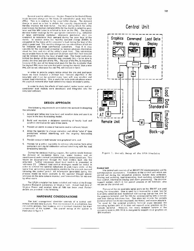
The load inanagsment sirnulator consists of a centr-al unit, remote unit and data sources. Five rnicrocoiiipulers, six monitors, two dot matrix printers. four niodems and a lei-niinal consisted the main components of the system. The overall set-up of the system is illustrated in figure 1.
Central Unit ----------------
I I
I I 1 PF I 4
r------ I 1
! A T IBM & M
I
I 1 1 I I I
- I
Standard 0" I - 1
F i g u r e 1. O v e r a l l Se tup of t h e LFLM S i m u l a t o r
Central Unit The central unit consists of an IBM-RT/PC microcomputer and its
comniuiiicatlon accessories. Functions of the central unit which are carried out during the simulation process include data collection, filtering and archiving, load forecasting, load modeling, scheduling of load control. inforrnation display and alarm processlng. The decision support system, which is the parent process of all functions, also resides on the central unit
Five out of the six available serial ports on the IBM-RT are used during the simulation. One is used by a terminal for a user, two for load data collection over hardwired and back-up dial-up line, one for the graphics terminal. and the fiflh for comnlunicatirig with a remote unit over dial-up telephone line. This does not include the console terminal which has its own keyboard, monitor(s), and mouse adaptors. l h e need for tlie external graphlcs terniinal arose because the operating system (AIX V1. l ) does not suppol? color gi-apliics on the console terminal. However, the newly released version of the operating system (AIX V2.0) is designed to support color graphics on IBM monitors.
126
Remote Unit An IBM-AT is used to represent the remote unit. This unit is
connected to tlie central unit by two auto-dial auto-answer modems over a telephone line Tlie purpose of the remote unit is to siniulate blocks of water heaters and air conditioners to be controlled by tlie central unit Transniission of control signals to residential load blocks are simulated by a graphics display on the color moiiitor of t l te IBM-AT computer. Water heaters and air conditioners are represented by two sets 01 blocks with two different colors on the monitor. A red spot on each block indicates that the unit is "ON", a green spot indicates that it is naturally " O F F " (due to diversified demand), and a flashing green indicates that the unit is "forced OFF" as a result of load c.ontiol schedule. The load blocks that are naturally "OFF" are selected randonily out of all blocks. The percentage of these blocks to tlie total number of blocks equals the diversity factor of the load at that hour.
Remote units are put in an "alert mode" waiting for calls from the central unit. When Ihe call is made, a dialogue is established between them to exchange information and acknowledyeineiit codes. One of three types of codes is associated with each rnessage to indicate its type. These messages arid signals can he divided inlo three types.- tnfornialioii signals. signals to s ta l l load control and signals to end load control Iiifoi-malion signals are used to display some information on the monitor. print it on tlie attached line printer and archive it as a source of infor niation for future activities. Aller receiving information signals, the remote unit s ta i ls tlie preparation to initiate load control. When the "stai-1'' signal is received. the contiol schedule is applied and the color panel is used to show the effect ol load conti.01 schedule on load blocks This process stays in effect iintil the "end" signal is received when the remote uiiit returns back to its normal operation. These control signals are initiated at tlie cetttral unit on the basis of a need for load control. the trelease of such controls due to payback and customer coiitfott considerations.
MAJOR FUNCTIONS OF THE SYSTEM
The L F L M simulator peifornis data collection, processing and archiving. load fotecasting. load modeling. load control. iiiforniatioit display and alrlimi processing. Each of these furictioiis requires certain amount of intelli!lencc depending on the sophistication of that function. Also. a level of rcduiidancy has been provided to each function to guarantee tlie uninterrupted operatioti of the system if one or more of these functions fail. Following sections describe the major funclions of tlie systein.
30 sec. Load Data
DATA COLLECTION, PROCESSING & ARCHIVING
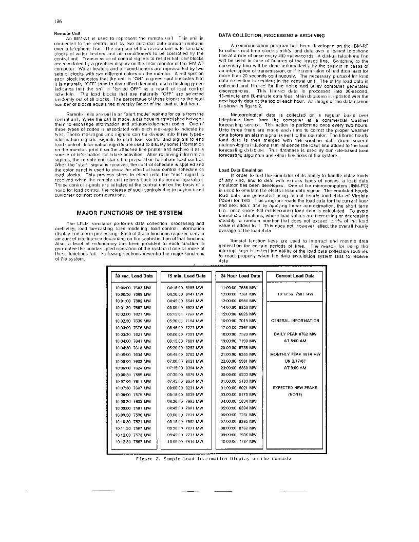
A communicatioii program has been developed on the IBM-RT to collect real-time electric utility load data over a leased telephone line at a rate of once every 400 milliseconds. A dial-up telepltone line wil l be used in case of failures of the leased line. Switchin<j to the secondary line will be done automatically by the system in cases of an interruption of traiisniission, or if transmission of bad data lasts for more than 20 seconds coiitinuously. Tlie necessai-y piotocol for load data collection is resident in the central unit The utility load data is collected and filtered for line noise and utility computer generated discrepancies. This filtered data is processed into 30-second, 15-minute and 60-minute data files. Main database is updated with the new houi-ly data at tlie top of each hour. An image of the data screen is shown in figure 2.
Meteorological data is colleLted on a regular basis over telephone lines from the cornputer at a commercial weather forecasting service. This action is performed once every two hours. Upto three trials are made each tinie to collect the ptoper weather data before an alarm signal is sent to the operator. The filtered hourly load data is then merged with tlie weatliei. data (11-orn several nieteorological stations that influence the load) and added to the load forecasting database. This database is used by our rule-based load forecasting algorithm and other funclions o f the system.
Load Data Emulation In order to test the simulator of its ability to handle utility loads
of any kiiid. and to deal with various types of noises. a load data emulator has been developed. One of the rnicroconiputers (IBM-PC) is used to emulate the electric load data signal. The emulated hourly load data a le generated using actual hourly load data of Virginia Power for 1986. This program reads the load data for t l ie current hour and next hour, and by applying lii iear appioxiination, the shorl term (i.e., once every 400 tnilliseconds) load data is calculated. To avoid unrealistic situations, where load values ate increasing o r decreasing steadily, a random nurnber that does not exceed * I % of the load value is added to it. This does not, however, affect the overall hourly average of the load data.
Special funclion keys are used to interrupt and resume data generation for ceilairi periods of tinie. The reason for using the interrupt keys is to test tlie abilily of the load data collection routines to react properly when the data acquisition system fails to receive data.
10 00 00 7683 MW 10 00 30 7669 MW 1001 00 7682 MW 1001 30 7667 MW 100200 7621 MW 10 02 30 7639 MW 10 03 00 7676 MW 100330 7621 MW 10 04 00 7641 MW 10 04 30 7618 MW 10 05 00 7634 MW 10 00 00 7603 MW 10 06 00 7624 MW 10 06 30 7599 MW 10 07 00 761 1 MW 10 07 30 7607 MW 10 08 00 7579 MW 10 08 30 7602 MW 100900 7581 MW 10 09 30 7536 MW 10 1030 7521 MW 10 11 30 7567 MW 10 12 00 7578 MW 10 12 30 7567 MW
I 15 min. Load Data
04:15:00 5965 MW 04:30:00 6147 MW 04:45:00 6541 MW 05:OO:OO 6923 MW 05:15:00 7282 MW 05.30:OO 7104 MW 05:45:00 7227 MW 06:OO:OO 7391 MW 06:15:00 7601 MW 06:30:00 8253 MW 06.45.00 8703 MW 07:OO:OO 9021 MW 07:15:00 9304 MW 07:30:00 8879 MW 07:45:00 8634 MW 08.OO:OO 8231 MW 08:15:00 8035 MW 08:30:00 7983 MW 08:45:00 7901 MW 09:OO:OO 7821 MW 09:15:00 7982 MW 09-30.00 7821 MW 09:45:00 7731 MW 10.00.00 7614 MW
I 24 Hour Load Data
11 00 00 7686 MW 120000 7361 MW 12 00 00 6980 MW 14 00 00 6853 MW 15 00 00 6926 MW 16 00 00 7019 MW 17 00 00 7367 MW 18 00 00 7523 MW 19 00 00 7199 MW 20 00 00 6736 MW 21 00 00 6355 MW 22 00 00 5981 MW 23 00 00 5369 MW 00 00 00 5233 MW 01 00 00 5183 MW 01 0000 5021 MW 03 00 00 51 79 MW 04 00 00 5834 MW 05 00 00 6394 MW
06 00 00 7251 MW 07 00 00 8395 MW 08 00 00 8762 MW 09 00 00 7935 MW 10 00 00 7787 MW
F i g u r e 2 . Sample Load I n f o r m a t i o n D i s p l a y o n t h e Conso le
Hourly load data are archived in different databases in addition to the niain database used by the forecast algotithni. In order to maintain a constant size of this database. the data file would be scrolled up at midnight (end of each simulated day) thus discarding the data of the oldest day. The load and weather forecasts for the new day are inserted at the end of the file, and are replaced by actual data when it becomes available.
LOAD FORECAST
A rule-based algorithm has been developed to provide accurate load forecast for one to twenty-four hours ahead. See references [1,2] for details. This load forecasting model is designed to perform under certain constraints. These are:-
1.
2.
The software should be transpottable to other computers:
The load forecast must be made available to several off-site users who would call in over voice grade telephone lines to check the load forecast and/or recent load hist0i.y; and
3. The load forecast algorithm should be self-learning and be specially sensitive to the following.
a) Holiday
b) Abnormal weather conditions
c) Seasonal changes in load
d) Changes in usage pattern
e) Effect of a rate change
0 Mix of energy sales by consumer class
g) System load management capabilities
A self-revising mechanism is a very important feature of the forecast algorithm. It is a knowledge-based routine used to review the overall scheme of the algorithm. modify the rule-base and recalculate some factors included in the mathematical forniulations. This revising mechanism is activated automatically wheri the forecast algorithm senses a change in the general pattern of the system load, o r when the error percentage exceeds certain limit due to wide variations in weather conditions. When the average of the highest errors (not the error at the peak hour) for three consecutive days exceeds 3%, the self-revising mechanism is activated. Early and late days of Spring and Fall usually require the activation of the revising mechanism more: than other times of the year. These transient periods have wide variation in weather conditions, and hence different electric load patterns.
The forecast algorithm with its revising mechanism has been found to be of high accuracy and reliability. When tested for 1986 weather and Virginia Power load data the absolute average forecast errors, consideriiig all hours of the day and all days of the season, came out to be 1.03096, 1.44096, 1.334% and 1.38996 for winter, spring, sumnier and fall seasons respectively. This results in an annual absolute average error of 1.298%. When the load forecast error for only the peak hour of the day is considered the seasonal average error ranges between 1.211% and 1.89596. This is based on data analysis for 626 days in 1983 and 1986. We were also interested to see, out of the 626 days tested, how many times we wete unable to predict the hour of the peak load for the day, not the peak load (MW) itself. We found that there were only nine such cases in these two years. See Rahrnan and Baba [ I ] for further details about the load forecast errors.
LOAD MODELLING
Another rule-based algorithm has been developed to simulate the behavior of residential loads (water heaters and air conditioners) under normal (uncontrolled) and control conditions. Available test results from different sources have been used for developing the mathematical models and to extract the rules that control tlie behavior of these devices. A database and a rule-base were coristructed for water heaters and air conditioners. Each model when called by the load control program wil l pull the required dala and rilles frorn these databases and the meteorological data from the niain database.
The diversified water heater load has bee:; found to be a function of the ambient temperature and time of day. Othor paianieters. such as house insulation. tank size, family size and sevet-al mcteorological parameters are included in tlie equations as constants Such an assumption is true wlieii the model reptesenls the average of several thousands of unils. The hourly diversifted demand of each unit can be described in the general formula 13):
Div.derna/?d = Jyp
where, Div. demand = Typ. demand =
a =
B = Y =
temp. = temPtvpd =
187
hourly diversified demand per unit in kW average hourly demand for that season as stored in the database kW constant changes from hour to hour over the day (0.05 to 0.2) constant changes from hour to hour over the day (15 to 80). o r temp. constant changes from hour to hour over the day (1 to 1.4) ambient temperature in O F
average temperature of the season as stored in the database, O F .
These models have been designed with three main objectives in mind.
1. Determine the normal diversified load characteristics of water heaters and air conditionets under different weather conditions;
2. Determine the impact of direct load control on the operation of each of these appliances; and
3. Determine the effects of different control strategies on the utility load shapes at different times of the day o r the season.
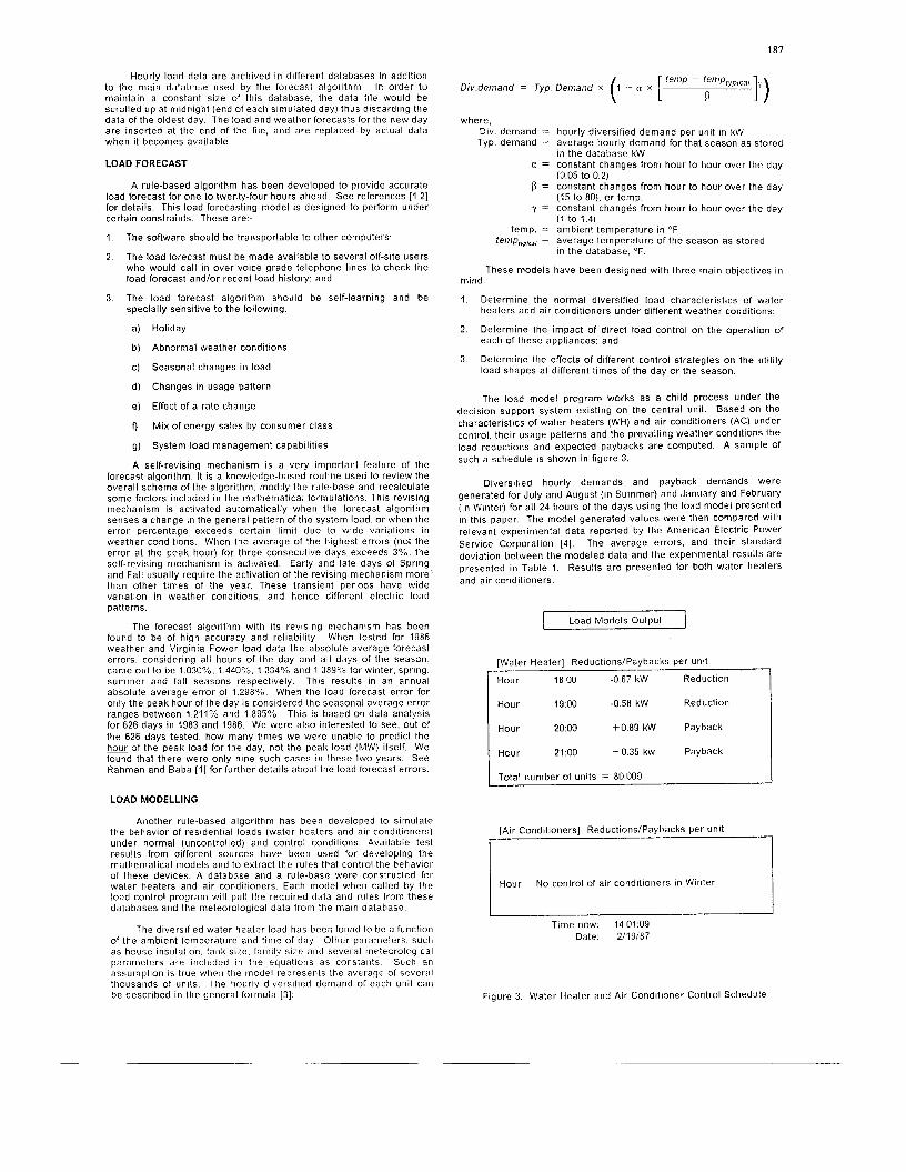
The load model program works as a child process under the decision support system existing on the central unit. Based on the characteristics of water heaters (WH) and air conditioners (AC) under control, their usage patterns and the prevailing weather conditions the load reductions and expected paybacks are computed. A sample of such a schedule is shown in figure 3.
Diversified hourly demands and payback demands were generated for July and August ( in Summer) and January and February ( in Winter) for all 24 hours of the days using the load model presented in this paper. The model generated values wet-e then compared with relevant experimental data reported by the American Electric Power Service Corporation [4]. The average errors, and their standard deviation between the modeled data and the experimental results are presented in Table 1. Results are presented for both water heaters and air conditioners.
I Load Models Outout 1
[Water Heater] Reductions1P;ybacks per unit
-0 67 kW Reduction
-058 kW Reduction
+ O 89 kW Payback
Hour t 0 35 kw Payback
Total number of units = 80,000
[Air Conditioners] Reductions/Paybacks per unit
2 Hour No conlrol of air conditioners in Winter
I t
Time now. 14.01:09 Date: 2119187
Figure 3. Water Heater and Air Conditioner Conttol Schedule

188
Load Type
Water Heaters
TABLE 1. Deviation of Modeled Values fromi Experimental Results (Yo)
Season Div Demand Payback Demand
av e i ror st dv av error st dv
Winter 8 7 3 6 7 3 4 1
Summer 5 4 3 1 6 2 3 1
1 Air Conditioners I Summer I 7.9 I 4 8 I 6.5 I 2.9 I
LOAD CONTROL PROGRAM
Each time a new load forecast is generated. the load control program is called to decide whether or not to initiate a load control. This program decides first on the rnaxiiiium load limit (Threshold) beyond which load coiitrol is to be required. As the long-term (upto a month) load forecast is dependent on the long-term weather forecast there are risks for drastic errors. Thus, the use of long-term load forecast was found inadequate for this purpose. An extensive study of the monthly electric peak loads of Virginia Power for the last 10 years has lead to another approach. If weather forecasts for one week o r more are available, then the historical monthly peak (for the month that best matches the current month) is adjusted for load growth, multiplied by 0.9 and used as the threshold value of the month. If no lony-term weather lorecast is available. the niiniinum of the peak loads of that month for last three years are selected and multiplied by 0.95 to obtain the threshold value. Whenever this threshold value is exceeded, the new peak value wil l replace the threshold value.
Testing this approach on nionllily electric load peaks of Virginia Power for the last three years have shown its practical use. First, the monthly peaks for the last three years were always more than the threshold value thus determined. and, second, due to the use of this threshold, load control was activated five times o r less per month.
If the forecasted electric load exceeds the threshold value, the control program takes a variety of actions. A warning message is sent to the system manager (on console and the central printer) and to all users informing them of the t ime and magnitude of new peaks. A sample of such a message is shown in figure 4. The top part of this figure shows a cautionary message that is issued under normal conditions. Only when a new peak is expected this message is changed lo a "warning" message as seen in the lower part of the figure. Load models would be called in to provide the not-mal diversified load pattern of customer appliances (as seen in figure 3) for that day. Based oii these patterns, the control ptogram will follow the rules of selecting the optitrial control strategy. Maxinium reduction at peak hour, avoidiiig custoriier inconvenience and niiniinum paybacks are some of the constraints that at-e active at the time. After selecting the control strategy(s), load models would be called agatii to construct the new system load shape. I f uiidesired changes in the load shape (viz., generating a new peak due to paybacks) are anticipated. niodifications would be made on the control schedule. When this schedule is finalized. a new niessaqe would be sent lo all users Also, remote units would receive details about this schedule. The load forecast algorithm would generate a niodified load forecast that includes the impact of Ihe control schedule. A sample of such load forecast with ai id without direct load control is shown in figure 5 The load forecast with DLC shows the effects of load control aitd the payback on the hoully loads. For example load reductions at 7:OO and 8.00 a m. result in a three hour payback. Finally, wlieii the t lme for starttng this schedule conies. signals would be transmitted to all remote units to implement the plan as specified.
CAUTION Forecasted load data wil l not exceed threshold value for the month for the rest of the day. No load control actions are planned. This message wil l be updated every hour.
Threshold value for the month = 8918 MW I Time now: 14.00:41
Date: 2/18/87
WARNING A new peak load that exceeds the threshold for the month is expectec today. The threshold will be exceeded as follows:
Threshold value for the month = 8918 MW
Expected load = 9026 MW at hour 18 00 Expected load = 9074 MW at hour 19:OO
Direct Load Control wi l l be initiated at hour 17:OO today. A load control schedule has been pi-epared. For more details enter the command "contiol". This message may be modified later, so please keep watching
Time now: 11:00:37 Date: 2/19/87
Figure 4. Caution and Warning Messages
I Modified 1 24-Hour Load Forecast
Load w l DLC hour Load w/o DLC
0 00 1 00 2 00 3 00 4 00 5 00 6 00 7 00 8 00 9 00
10 00 11 00 12 00 13 00 14 00 15 00 16 00 17 00 18 00 19 00 20 00 21 00 22 00 23 00
5772 MW 5612 5664 5698 5850 6309 7363 7972 7899 7665 7401 7198 6862 6681 6546 6548 6838 7329 7591
7132 6805 6295 5775
7384
5772 MW 5612 5664 5698 5850 6309 7363 7870 Red. 7865 Red. 7734 Pbk. 7447 Pbk. 7206 Pbk. 6862 6681 6546 6548 6838 7329 7591 7384 7132 6805 6295 5775
Date. 3/12/1987 9 47 22 Time Now:
Figure 5. Load Forecast with and without DLC
189
INFORMATION DISPLAY & ALARM PROCESSING
Two types of alarm and warning signals are generated by the system - hardwarelsoftware failure and warnings related to contr-ol activities. In the first type, warning messages are "flashed" on the console terminal of the system manager indicating the time and type of problem. Each activity and each function of the system is attached to a certain debugging shell written in C language. This shell checks the development of each step of these functions and also checks for the returned code of each exit statement. If the source of error is defined in the debugging shell, some corrective actions are taken. For example, either an additional attempt is made t o perform the function (e g., weather data collection) o r an alternative hardware o r software is used. In both cases the alarm signal is sent to the operator. l h e alarm signal is also transmitted to al l users if there was a serious failure in one of the functions of the system that affects its reliability (such as tolal loss of load data). In such a case, the decision support system will suspend most of the control activities of the system. If the source of error is unknown then the decision support system suspends the control activities, but continues with the data collection and archiving.
THE DECISION MAKING PROCESS
The decision support system is the parent process of all functions and commands of the software package. This system is a collection of programs written in C and AIX commands. AIX is a multi-tasking multi-user operating system derived from UNIX. This collection of programs and commands forms a "shell" environment for all functions of the system and controls the overall step-by-step activities of the LFLM simulator. Sorrle of the housekeeping functions of this simulator include:
1.
2.
3.
4.
5. organize data transfer between different functions of the
6. provide an interface for the system manager to make
Activatiori and deactivation of the decision making process is a privilege of the super user (the system manager) only The AIX command "crontab" IS one of the most important commands in that set. It is used to run certain functions at regular intervals o r indefinitely, such as collecting weather data once every two hours. Some functions that require the prior completion of other functions are put in a "wait" state until those functions are completed.
control all activities on the system:
synchronize system functions with each other;
guarantee an uninterrupted operation of the system;
take certain measures in case of emergency;
system; and
changes o r modifications without interrupting any process.
The decision making process monitors each function carefully to assure a successlul completion of that function before proceeding to the next one. An exit code is returned lo the parent process from each function or command indicating its exit status. and each code has a different meaning For example, a '0' exit code indicales a successful completion of the process, other codes usually refer to certain hardware o r sonware problems. The parent process takes different measures upon the receipt of an erroneous code. In case of a serious problem that cannot be corrected automatically. the decision making process wil l not activate load control. However, other functions such as data acquisition and load forecast wi l l remain active if the problem does not affect them.
The operator can terminate. modify o r force the activation of any function without interfering with othei- functions on t l ie system. In case of function termination, the operator can "kill" that process of that function without interrupting othr!r ones. The returned code of the terminated pi-ocess wil l be a '0' indicating a successful completion of the process. This will avoid any aulornatic corrective actions by the parent process.
EVALUATION OF THE SYSTEM
The load forecasting-load management simulator has been constructed and tested at the Energy Systems Research Laboratory at Vi!-ginia Tech. Its simulation capability has been tested extensively using actual load and weather data of 1986. Also. the system has been subjected to different types of hardware and software problems to test its ability to take tlie riecescar-y corrective actions. This simulation process has revealed the following.
~
0
0
0
0
1
2
3
4
The system can operate continuously for long periods of t ime without any human intervention
The system has the ability to correct many of the software and temporary hardware problems without the need for human intervention.
In case of permanent hardware failure of some units, the system can switch automatically to other stand-by units. Warning messages are sent to the operator.
Load control decisions are accurate in more than 98% of cases. All of these decisions and the implementation of them are done in a fully automated fashion.
The major rule-based functions of the system are supported by the built-in self-revising mechanisms.
Operating such systems does not require extensive training. The operator needs to know how to start the system and how to make some hardware tests in cases of failure.
The system uses low-cost microcomputers and communication components.
System operator and other users are supported by an intelligent data management and information center which enables them to access the required data easily and quickly.
REFERENCES
S. Rahman and M . F. Baba, "Software Design and Evaluation of a Microcomputer-Based Automated Load Forecasting System". submitted for presentation at the IEEE Winter Power Meeting, 1988.
S. Rahman and R. Bhatnagar. "An Expert System Based Algorithm for Short-Term Load Forecast", presented at the 1987 Winter Power Meeting, New Orleans, LA, February, paper no. 87WM082-1.
M. F. Baba, "Intelligent and Integrated Load Management System". Ph.D dissertation, Electrical Engineering Department. Virginia Tech, August 1987.
"The Economic Feasibility of Direct Control Residential Load Management on the AEP System", American Electric Power Service Corporation, November 1982.
__
Sailur Rahman (S-75, M-78, SM-83) graduated from the Bangladesh University of Engineering and Technology in 1973 with a B. Sc. degree in Electrical Engineering. He obtairied his M.S. degree in Electrical Sciences from the State University of New York at Stony Brook in 1975. His Ph D. degree (1978) is in Electrical Engineering from the Virginia Polytechnic Institute and State University.
Saifur Rahman has taught in the Department of Electrical Engineering, the Bangladesh University of Engineering and Technology, the Texas A&M University and the Virginia Polytechnic Institute and State University where he is a Professor. His industrial experience includes work at the Brookhaven National Laboratory, New York arid the Carolina Power and Light Company. He is a Senior Member of the IEEE Power Engineering Society. He selves on the System Planning and Demand Side Management subcornniittees of the IEEE Power Engineering Society. His areas of interest are demaiid side management, power system planning, alternative energy systems and expert systems. He has authored rnore than 75 technical papers and reports in these areas.
Mutasim Baba (S-86) was born in Tulkarni. Jordan, on March 2, 1959. He received his B.S. degree with distinction in electrical engineering in 1982 from the University of Jordan, Amman, Jordan. He worked for one year as an instructor at An-Najah National University irr the West Bank of Jordan. 111 1985. he obtained his M.S. degree in Architectural Engineering (The Environmental Option) from the Pennsylvania State University. He has completed his P1i.D. in Electrical Engineering at the Virginia Polytechnic Institute and State University in 1987. His areas of interest include mici-ocomputer applications in power systems, computer aided design and energy management He has authored several technical papers and reports in these areas.
Related Documents