AN INTEGRATED APPROACH TO HYDROGEN PRODUCTION FROM AGRICULTURAL RESIDUES FOR USE IN URBAN TRANSPORTATION Jalal Abedi 1 , Yaw D. Yeboah 1 , Matthew Realff 2 , Denis McGee 3 , Jan Howard 4 , and Kofi B. Bota 1 1- Clark Atlanta University, 223 James Brawley Dr., Atlanta, GA 30314 2- Georgia Institute of Technology, Atlanta, Georgia 30332 3- Enviro-Tech Enterprises Inc., 10555 Paces Ave. #415, Matthews, NC 28105 4- Scientific Carbons Inc., 253 North Bay, Blakely, GA 31723 Abstract This project focuses on the use of agricultural residues such as peanut shells to produce hydrogen for urban transportation. Specifically, a side stream of the pyrolysis products of a process for making activated carbon from densified peanut shells at Scientific Carbons Inc. in Southwest Georgia will be used to test the concept. The primary focus of this work was to undertake process development studies in the use of the large quantities of peanut shells produced in Georgia as feedstock for the pyrolysis-steam reforming process. The method combines two stages: slow pyrolysis of biomass to generate charcoal and catalytic steam reforming of the pyrolysis vapors to hydrogen and carbon dioxide. Scientific Carbons Inc. is currently operating a pilot facility in Blakely, GA to convert 24 tons/day of pelletized peanut shells to activated carbon. Scientific Carbons facility will be used to perform a scaled-up demonstration of a steam reforming process to convert the off-gas of the peanut shell carbonization process to hydrogen. As a small company with the demonstrated ability to build modular systems, their current processes could be modified and expanded to run a variety of other feedstocks and to make a range of alternative products. This year we focused on development of decision models for selecting feedstock, process and alternatives, and the design and management of the construction of a 7-kg/hr fluidized-bed catalytic reactor system. The catalytic reactor system was successfully constructed and shipped to NREL. Shakedown runs of the system are expected to be completed in summer 2001.

Welcome message from author
This document is posted to help you gain knowledge. Please leave a comment to let me know what you think about it! Share it to your friends and learn new things together.
Transcript

AN INTEGRATED APPROACH TO HYDROGEN PRODUCTIONFROM AGRICULTURAL RESIDUES FOR USE
IN URBAN TRANSPORTATION
Jalal Abedi1, Yaw D. Yeboah1, Matthew Realff2, Denis McGee3, Jan Howard4, andKofi B. Bota1
1- Clark Atlanta University, 223 James Brawley Dr., Atlanta, GA 303142- Georgia Institute of Technology, Atlanta, Georgia 30332
3- Enviro-Tech Enterprises Inc., 10555 Paces Ave. #415, Matthews, NC 281054- Scientific Carbons Inc., 253 North Bay, Blakely, GA 31723
Abstract
This project focuses on the use of agricultural residues such as peanut shells to produce hydrogenfor urban transportation. Specifically, a side stream of the pyrolysis products of a process formaking activated carbon from densified peanut shells at Scientific Carbons Inc. in SouthwestGeorgia will be used to test the concept. The primary focus of this work was to undertakeprocess development studies in the use of the large quantities of peanut shells produced inGeorgia as feedstock for the pyrolysis-steam reforming process. The method combines twostages: slow pyrolysis of biomass to generate charcoal and catalytic steam reforming of thepyrolysis vapors to hydrogen and carbon dioxide. Scientific Carbons Inc. is currently operating apilot facility in Blakely, GA to convert 24 tons/day of pelletized peanut shells to activatedcarbon. Scientific Carbons� facility will be used to perform a scaled-up demonstration of a steamreforming process to convert the off-gas of the peanut shell carbonization process to hydrogen.As a small company with the demonstrated ability to build modular systems, their currentprocesses could be modified and expanded to run a variety of other feedstocks and to make arange of alternative products. This year we focused on development of decision models forselecting feedstock, process and alternatives, and the design and management of the constructionof a 7-kg/hr fluidized-bed catalytic reactor system. The catalytic reactor system was successfullyconstructed and shipped to NREL. Shakedown runs of the system are expected to be completedin summer 2001.

Introduction
Background
Hydrogen is the most environmentally friendly fuel and can be efficiently used for stationarypower and mobile applications. When burned or oxidized, it generates water as the onlyemission (small amounts of NOx are generated during the combustion process but can becontrolled to very low levels). At present, hydrogen is produced almost entirely from fossil fuelssuch as natural gas, naphtha, and coal. During these hydrogen production processes, largeamounts of fossil-derived CO2 are released to the atmosphere. Renewable biomass is anattractive alternative to fossil feedstocks because of essentially zero net CO2 impact [1].
Biomass is defined as a material that has participated in the �growing cycle.� Agriculture waste,forest residue, urban wood waste, and trees and grasses grown as energy crops are materialscommonly referred to as biomass. Because biomass consumes as much CO2 in the growingcycle as is produced when it is transformed into energy, the net CO2 contribution from biomass-derived fuels is considerably less than from fossil-derived fuels. In addition, producing biomasson a sustainable basis by growing energy crops will support Georgia�s agricultural sector, animportant part of the state�s economy. Successful commercialization of this technology will alsoreduce oil and gas imports of the U.S. [1].
Agriculture is Georgia�s largest industry and contributes over $46 billion to the state�s annualeconomic output. One in six Georgians work in an agriculture-related sector. Georgia ranks asthe number one state in the U.S. in peanut production, producing about 45% of all peanuts grownin the U.S. Georgia farmers grew about 1.5 billion pounds of peanut in 79 counties in 1999.Disposal of the large quantity of peanut shells in an environmentally acceptable manner is asignificant challenge for the peanut industry. Hence peanut shells have been targeted as afeedstock for conversion to hydrogen.
The National Renewable Energy Laboratory (NREL) in Golden, CO has developed the basis of atechnology for the generation of hydrogen from biomass and agricultural residue [2,3]. Biomasscan be converted to hydrogen by two distinct strategies: 1) gasification followed by shiftconversion and 2) pyrolysis of biomass to form a bio-oil that can be subsequently converted tohydrogen via catalytic steam reforming and shift conversion. The NREL technology uses thelatter approach, which has the potential to be cost competitive with current commercial processesfor hydrogen production [4]. The process has been demonstrated at the bench scale using modelcompounds and the carbohydrate-derived fraction of bio-oil [2,3]. This concept has severaladvantages over the traditional gasification technology. Bio-oil is easily transportable so thesecond step (steam reforming) can be carried out at a different location, close to the existinginfrastructure for hydrogen use or distribution. The second advantage is the potential forproduction and recovery of higher-value co-products from bio-oil that could significantly impactthe economics of the entire process.
The bio-oil produced from fast pyrolysis of biomass contains about 75-85 wt% organics and 15-25% water [2,3]. The latter is the result of the moisture content in the biomass feed anddehydration reactions which proceed in parallel with the thermal depolymerization reaction. The

organics are generally a mixture of aldehydes, alcohols and acids derived from the carbohydratefraction of biomass, and phenolics derived from the lignin fraction. Fast pyrolysis produces abio-oil made up of two distinct fractions: a monomer-rich aqueous fraction (containing typically20 wt% organics) and a hydrophobic fraction composed mainly of oligomers derived fromlignin. Steam reforming can be used to convert the entire bio-oil or each of the fractions of theoil.
The hydrogen content in biomass is relatively low (6-6.5%), compared to almost 25% in naturalgas. For this reason, producing hydrogen via the biomass gasification/water-gas shift processcannot compete on a cost basis with the well-developed commercial technology for steamreforming of natural gas. However, an integrated process, in which part of the biomass is used toproduce more valuable materials or chemicals and the residual fractions are used to generatehydrogen, can be an economically viable option.
The overall steam reforming reaction of bio-oil or any oxygenated organic compound with achemical formula of CnHmOk can be represented as:
CnHmOk + (2n-k)H2O = nCO2 + (2n+m/2-k)H2
The stoichiometric yield of hydrogen is 2+m/2n-k/n moles per mole of carbon in feed. A massbalance of the NREL approach using fast pyrolysis is shown in Figure 1.
Figure 1. NREL Biomass to Hydrogen Processbased on fast pyrolysis with phenolic coproducts.
Biom ass [100]
Fast Pyrolysis
fractionated bio-oil [45 organic](aqueous fraction)
FBR C atalyticSteam R eform ing
crude bio-oil � water [10] � organic [60]
co-products � gases [15] � char [15]
F ractionation
co-products � lignin-derived o ligom ers (phenolics) [15 organic ]
H 2 [6]CO 2[60]
H 2 [5]
CO 2[40]
CO [10]
Shift conversion
W ater [10]
W ater [11]

Prior Work
In previous years it was demonstrated, initially through micro-scale tests then in the bench-scalefixed-bed reactor experiments [2,5,6], that bio-oil model compounds as well as the carbohydrate-derived fraction of bio-oil can be efficiently converted to hydrogen. Using commercial nickelcatalysts the hydrogen yields obtained approached or exceeded 90% of those possible forstoichiometric conversion. The carbohydrate-derived bio-oil fraction contains a substantialamount of non-volatile compounds (sugars, oligomers) which tend to decompose thermally andcarbonize before contacting the steam reforming catalyst. Prior studies managed to reduce theseundesired reactions by injecting the oil fraction to the reactor in a form of a fine mist. However,the carbonaceous deposits on the catalyst and in the reactor freeboard made most of the catalystinaccessible to contact with the oil, limiting the reforming time to 3-4 hours. For the abovereasons, NREL decided to employ a different reactor configuration, a fluidized bed, to overcomeat least some limitations of the fixed-bed unit. This greatly increased the reforming efficiencyand extended the catalyst time-on-stream. Catalyst regeneration was done by steam or carbondioxide gasification of carbonaceous residues providing additional amounts of hydrogen.
Experiments at NREL
Pelletized peanut shells were obtained from Scientific Carbons Inc. in Georgia. These materialswere pyrolyzed at the NREL Thermochemical Users Facility (TCUF) using the fast ablativepyrolysis system (vortex reactor). The reactor wall temperature was maintained within the rangeof 600-625°C, which has been proven to provide the highest bio-oil yield. Nitrogen at a flowrate of 15 kg/h was used as the carrier gas for the biomass particles in the pyrolysis reactor. Thetests proceeded smoothly at the rate of 10 kg/h. Eventually, 200-300 kg of pyrolysis oil wasgenerated from feedstock. Peanut shell oil was collected in the scrubber of the pyrolysis systemas a two-phase liquid (water was used for scrubbing pyrolysis vapors), with the top fractioncontaining 32.3% organics (6% are lignin-derived oligomers) and 67.7% water. Water contentof the liquids was determined by Karl-Fisher titration method using a Metrohm 701 KF Titrinoanalyzer. Elemental composition, including the carbon, hydrogen, and oxygen content of theseliquids was analyzed by a commercial laboratory (Huffman Laboratories, Golden, CO). Theaqueous solutions were then used in reforming tests to produce hydrogen.
Fluidized Bed Reforming System
The experiments were carried out using a bench-scale fluidized-bed steam reformer. Theschematic of the fluidized bed system is shown in Figure 2. The two-inch-diameter Inconelreactor supplied with a porous metal distribution plate was placed inside a three-zone electricfurnace. The reactor contained 150-200g of commercial nickel-based catalyst from UCI (C11-NK) ground to the particle size of 300-500µm. The catalyst was fluidized using superheatedsteam, which was also a reactant in the reforming process. Steam was generated in a boiler andsuperheated to 750°C before entering the reactor at a flow rate of 2-4 g/min. Liquids were fed ata rate of 2-5 g/min using a diaphragm pump. A specially designed oil injection nozzle suppliedwith a cooling jacket was used to spray liquids into the catalyst bed. The oil temperature in theinjector was controlled by a coolant flow and maintained below boiling point to preventpremature evaporation of volatiles and consequent deposition of nonvolatiles. The condensatewas collected in a vessel whose weight was continuously monitored. The outlet gas flow rate

was measured by a mass flow meter and by a dry test meter. The gas composition was analyzedevery 5 minutes by an MTI gas chromatograph. The analysis provided concentrations ofhydrogen, carbon monoxide, carbon dioxide, methane, ethylene, and nitrogen in the outlet gasstream as a function of time. The temperatures in the system as well as the flows were recordedand controlled by the OPTO data acquisition and control system.
Figure 2. Schematic of the fluidized bed reforming system.
The measurements allowed determination of the total and elemental balances for the reformingtests as well as the calculation of the yield of hydrogen generated from the biomass-derivedliquid feed. The maximum (stoichiometric) yield of hydrogen was 2+m/2n-k/n moles per mole ofcarbon in feed. Therefore, 63 g of hydrogen could be theoretically obtained from 1 L of peanutshell oil extract. The steam reforming experiments in the fluidized bed reactor were carried outat the temperature of 800°C and 850°C. The steam to carbon ratio varied from 7 to 13, while themethane-equivalent gas hourly space velocity GC1HSV was in the range of 1200-1500 h-1. Gascomposition (on nitrogen free basis) obtained from the peanut shell pyrolysis oil is shown inFigure 3. During eight hours of the experiment, the gas composition was very stable and only asmall decrease in the concentration of hydrogen and an increase in methane were observed.
Methane concentration, though it grew to 3000-4000 ppm, still remained an order of magnitudesmaller than that of the three major gas components and, therefore, is not shown in Figure 3.More fluctuation was observed in the amount of gas produced and, consequently, in the yield ofhydrogen from the peanut bio-oil fraction, which is presented in Figure 4. The hydrogen yield
Nitrogen
Electric
Boiler
Water
Orifice
Flow
Meter
Mass Flow
Controller
Super
heater
Mass Flow
Controller
Nitrogen
Chiller
Liquid
Feed
Scale
Liquid
Pump
Solids
Collector
2" Fluid Bed
Reactor
78513Dry Test
MeterCondensate
Collector
and Scale
Heat Exchangers
MTI Gas
Chromatograph
Mass Flo
Meter

was still at the level of 80% of the stoichiometric potential after eight hours on stream. Peanutshell liquid had a higher concentration of the organic compounds, especially of lignin oligomersthan the wood oil fractions. Large molecules of lignin compounds are less reactive and probablyrequired a longer contact time with the catalyst than the smaller carbohydrate-derived fragments.They are also more likely to form carbon deposits on the catalyst surface. However, at 850°C,these deposits were removed and converted to hydrogen and carbon oxides by steam processingwith the same efficiency as that observed for wood-derived liquids (carbon to gas conversion of92%). This resulted in hydrogen yields greater than 80% of the stoichiometric potential duringeight-hour catalyst time on stream.
The yields of hydrogen would be 5-7% higher if the reforming was followed by water-gas shiftprocessing of carbon monoxide in the product gas. The global mass balance closure for thewhole experiment was 94%, and 88-91% of bio-oil carbon was converted to gases. Both thedecrease in the hydrogen production and the missing carbon in the mass balance suggest that asmall part of the carbon from bio-oil formed deposits on the catalyst surface. Steam treatment ofthe used catalyst performed at 850°C resulted in the release of hydrogen and CO2 in the amountcorresponding to 4-5% of the carbon fed (about half of the missing carbon). The other part ofcarbon unaccounted for was probably entrained by product gases together with the catalyst finesand collected in the cyclone and condensers. The steam treatment - by removing deposits fromthe surface - also regenerated the catalyst, which performed during the following test at the samelevel of activity as the fresh catalyst.
Figure 3. Composition of the gas produced during steam reforming of peanutshell bio-oil carbohydrate-derived fraction at 850°C and S/C=9 [3].
0
10
20
30
40
50
60
70
80
0 100 200 300 400 500
Tim e, m in
% vol
CO

Figure 4. Yield of hydrogen obtained during reforming of peanut shell bio-oilcarbohydrate-derived fraction at 850°C and S/C=9 [3].
Process Economics
The work performed at NREL to date has focused on the scenario shown in Figure 1 for fastpyrolysis. The economics of this approach has been assessed with an adhesive coproduct and theselling price of hydrogen is estimated in the range of $6-8/MBTU [4]. This study addressesanother process option based on slow pyrolysis, which is currently practiced to produce charcoalfor conversion to activated carbon. A modification of this approach to convert the by-products tohydrogen is shown in Figure 5. A preliminary economic analysis of the steam reforming of thebio-oil produced from the activated carbon process has been performed by NREL [5,6]. Theprocess examined included steam reforming of the slow pyrolysis vapors, followed by furtherhydrogen production in shift reactors and hydrogen purification in a conventional pressure swingadsorption (PSA) system. The base case process assumes utilization of all of the 225 kg ofpyrolysis vapors/hr (the current scale of the Scientific Carbons process). At this utilization rate, itappears that the carbon process is still slightly positive with respect to energy, although this willdepend on heat losses. In other words, the process produces enough energy to sustain the systemwithout requiring additional fuel.
The yield of hydrogen from the slow pyrolysis bio-oil is significantly higher (~70%) on a massbasis than that from the fast pyrolysis bio-oil. When looking at the total process (i.e., biomass tobio-oil to hydrogen), however, the yield from the slow pyrolysis process is lower than that fromthe fast pyrolysis process. Table 1 compares the yields from both processes. As shown in Table1, the yield of hydrogen from bio-oil in the fast pyrolysis system is roughly 11%, but in the slow
0
20
40
60
80
100
120
0 100 200 300 400 500
Tim e, m in
Yield, % sto
R eform ing

pyrolysis case, it is almost 19%. However, the yield on a total dry biomass basis is 4.5% forslow pyrolysis and 7.3% for fast pyrolysis. The primary reasons for these differences arevariations in the bio-oil composition, yield of other products, and process assumptions.
Also shown in Table 1 are estimates of the composition of the bio-oil from both processes. Inthe fast pyrolysis process, the bio-oil has a composition that is < 50% carbon, but that from theslow pyrolysis process has a carbon composition of almost 73% [5]. Thus, for the same steamaddition rate (i.e., lb H2O/lb C), more hydrogen will be produced per pound of bio-oil in the slowpyrolysis process.
Figure 5. Proposed process based on reforming of slowpyrolysis oils.
The economic feasibility determination was based on a discounted-cash-flow rate of return(DCFROR) analysis using a 10% rate of return. All parameters for the study were taken from thestandardized hydrogen economic analysis [6]. Table 2 summarizes the important economicparameters.
Biomass [100]
Pyrolysis
FBR CatalyticSteam Reform ing
Vapors and gases � water [30] � organics [25] � gases [10]
Charcoal [35]]
H 2 [7.6] CO 2 [80.6]
H 2 [6.7]
CO2[60.5]
CO [12.8]
Shift conversion
Activation
Activatedcarbon [15]
O ther [20]
S team [15]
S team [8.2]

Table 1. Yield Comparison for Slow and Fast Pyrolysis
Process Slow Pyrolysis Fast PyrolysisBio-oil Yield (kg/kg dry feed) 0.239 0.657Hydrogen Yield(kg/kg dry feed)(kg/kg bio-oil)(kg/kg vapor)(kg/kg dry vapor)
0.0450.1890.0630.113
0.0730.111NANA
Bio-Oil Ultimate Analysis (wt%)CarbonHydrogenNitrogenSulfurOxygen
72.505.131.20.0421.13
48.716.610.00.044.68
NA � Not applicable; the vapors are not processed in the fast pyrolysis process
Table 2. Standard Economic ParametersEconomic Parameter Value
Discount rate 10%Plant life 20 yearsDepreciation NoneConstruction Period 3 yearsOn-stream time Year 1 45%
Year 2+ 90%
Capital costs were scaled from Mann [4] using a 0.84 exponent. This exponent was derived fromthe three cases presented in the paper [4]. Fixed operating costs and working capital were alsobased on the paper. Variable operating costs were determined from the material balance. Thepyrolysis vapor was assumed to be available at $2.56/GJ, a value that is roughly 90% of its fuelvalue (assuming an energy equivalence to natural gas at $2.50/GJ). The analysis also assumedthat steam would be produced in the reforming operation. A credit based on $3.50/1000 lbs ofsteam was assumed.
Using the above assumptions, the total capital investment for the additional equipment to modifythe existing facility to produce hydrogen from the pyrolysis off-gas is estimated at $1.4 million.For an annual hydrogen production rate of 4.4 million Nm3, the selling price of hydrogen isestimated to be $9.51/GJ. The hydrogen-selling price for a fuel cost of $1.28/GJ (i.e., 45% fuelvalue) is $7.78/GJ. Using a no-cost bio-oil the selling price for the hydrogen is $6.05/GJ. Theseprice ranges are very promising considering that the economics were performed for a very small-scale operation.
Advantages and Potential Impact
The proposed method combines two stages: pyrolysis of biomass to generate bio-oil and catalyticsteam reforming of the bio-oil to hydrogen and carbon dioxide. This concept has several

advantages over traditional gasification technology. First, bio-oil is much easier to transport thansolid biomass and therefore, pyrolysis and reforming can be carried out at different locations toimprove the economics. For instance, a series of small size pyrolysis units could be constructedat sites where low cost feedstock is available. The oil would then be transported to a centralreforming plant located at a site with an existing hydrogen storage and distribution infrastructure.A second advantage is the potential production and recovery of higher value added co-productsfrom bio-oil that could significantly impact the economics of the entire process. In the originalNREL concept, the preferred route leads to co-products hydrogen and partly "depolymerizedlignin." Lignin-derived oligomer-rich fraction can be used as a feedstock for the production ofresins with formaldehyde. Such resins can become valuable co-products (a substitute for phenol-formaldehyde), which will lower the production costs of hydrogen from the aqueous fraction asdemonstrated in related technoeconomic studies [4]. Other viable application of the lignin-derived fraction is the production of �oxyaromatic ethers,� a new class of high-octane fueladditive. The economics of the whole bio-oil reforming are less favorable than for the co-product strategy. However, the hydrogen yields obtained from the whole oil are higher than inthe case when only the aqueous, carbohydrate-derived fraction is processed. In addition, sincehydrogen is the only product, this option is independent of co-product markets.
A key partnership that will be fostered in this project is with the Federation of SouthernCooperatives, an organization of southern family farmers that represent 25,000 farmers in a 13-state region. As part of the assessment for expanded application of this technology, we willdevelop a database of the biomass and agricultural residues (and their volumes) that may be usedas potential feedstocks in the proposed conversion scheme. The information from the databasewill be used to assess the economic and environmental impact of the proposed work on the stateof Georgia.
The anticipated potential benefits or impact on the Georgia economy include:• Use of biomass will support and further expand the agriculture-related sector, which is the
largest industry in Georgia; employing one in six Georgians and producing 45% of the U.S.peanut production.
• Application of the proposed technology will provide an economical and environmentallyacceptable means of disposing of the large quantity of peanut shells that result from the 1.5billion pounds (768,500 tons) of peanut produced each year in Georgia. The demand forpeanut shells as feedstock of the proposed technology will improve the economiccompetitiveness of the peanut industry in Georgia and secure its long-term future.
• Widespread use of renewable hydrogen, the cleanest fuel for power generation and fortransportation applications, will reduce oil and gas imports and will have significantenvironmental and health benefits for the major cities in the state of Georgia.
• The proposed process will produce co-products in addition to hydrogen. Alternative co-products that may be obtained from different bio-oil fractions include phenol (for phenol-formaldehyde resins) and fuel oxygenates. Similar to petroleum crude oil, biomass pyrolysisoil can be used for the production of a multitude of fuel and chemical products, in addition tohydrogen.
• The development of new agro-industrial infrastructure options that could result in sustainableand equitable growth. The inclusion of small farms and the attention to the appropriate scale

of production technology will ensure the ability to distribute the benefits of enhancedmaterials along the value chain to the communities involved in generating the wealth.
Approach and Accomplishments
Feedstock Supply, Process Economics, and Deployment Strategy
The ultimate impact of the biomass-to-hydrogen process depends on overall economics.Feedstock issues, such as supply, cost and logistics are major factors in cost-effectiveness of thehydrogen production process. This task is developing decision models for selecting amongfeedstock, process, and deployment alternatives. Of particular interest in Phase 1 on this projectare peanut shells supply and cost projections and the evaluation of other agricultural residuefeedstocks available in the same geographical area. Process economics are being developed forthe major process options and used to construct a process options database. Different networkoptions are developed to determine optimum subdivision of tasks among potential sites and todevelop criteria for location of new processing sites. The evaluation of other coproducts are alsoincluded. This work is utilizing Geographical Information Systems (GIS) databases forconstructing various scenarios relative to feedstock location, plant location and hydrogen and co-product markets.
Process Modeling
The current process converts peanut hulls into activated carbon and derives a bio-oil for fuel viapyrolysis. The process modeling effort is directed towards evaluating the enhancement of thisbasic process with options to recover a phenolic fraction for further processing into adhesivesand steam reforming and hydrogen purification for a transportation fuel. The main unitoperations that can achieve this separation and further refining are liquid-liquid extraction (LLE),steam reforming and pressure swing absorption (PSA). Three alternative flowsheets for theprocess are shown in Figures 6, 7 and 8. To model the LLE process it is necessary to establishthe solubility of various components of the bio-oil in water and organic solvents. To achieve thisgoal it is necessary to characterize and model the bio-oil that is generated from the pyrolysisprocess and to ensure that the phase behavior of the components is adequately described in theprocess simulator. The description of the bio-oil components has been the main focus of theeffort in process modeling at this stage. We have tried to identify key component classes, andrepresentative components within these classes that can be used to test the ability of the processsimulator to match the phase behavior of the components.
Prior to developing a model for simulating the processing of biomass derived pyrolysis oils, anattempt to characterize these oils was undertaken. This course of action involved both a surveyof the existing literature to identify compounds prevalent in pyrolysis oils, as well as an attemptto use HYSYS, a process simulator package from Hyprotech, to simulate a typical process oilwith a few representative compounds for further analysis.

Pyrolysis Unit
Biomass
Pyrolytic Oil
Water
Phenolic Fraction foruse in Adhesives
Gases
Char
Aqueous FractionSteam Reformer
Steam
Pressure SwingAbsorption Unit
Purified H2 Gas
H2 & CO2 Gas
Waste Gas
LLX Column
1
2
3
Design Parameters1a) Water Flowrate1b) Column Sizing1c) Separation Purity
2a) Steam Flowrate2b) Reformer Size2c) Gas Composition
3a) PSA Unit Sizing3b) Operating Pressures3c) PSA Operating Costs3d) H2 Purity
Figure 6. Stage Aqueous Extraction
Figure 7. Stage Simultaneous Extraction
Pyrolysis Unit
Biomass
Pyrolytic Oil
Solvent (MIBK)
MIBK Soluble Fraction
Gases
Char
Aqueous FractionSteam Reformer
Steam
Pressure SwingAbsorption Unit
Purified H2 Gas
H2 & CO2 Gas
Waste Gas
Water Solvent Recycle
Phenolic Fractionfor use in Adhesives
LLX Column
Evaporatoror Column
1
2
3
4
Pyrolysis Unit
Biomass
Pyrolytic Oil
Solvent (MIBK)
MIBK Soluble Fraction
Gases
Char
Aqueous FractionSteam Reformer
Steam
Pressure SwingAbsorption Unit
Purified H2 Gas
H2 & CO2 Gas
Waste Gas
Water Solvent Recycle
Phenolic Fractionfor use in Adhesives
LLX Column
Evaporatoror Column
1
2
3
4

Figure 8. Stage Extraction
In general, the range and variety of chemicals found in pyrolysis oils shown in Table 3, farexceed that of crude oil to which analogies are often drawn. The key difference between bio-oiland crude oil is the prevalence of oxygenated compounds in bio-oil as opposed to fully reducedhydrocarbons in crude oil. However, some trends can still be noted due to the shared biologicalcomponents common to the majority of plant life from which many pyrolysis oils are derived. Inparticular, the presence of cellulose and other polysaccharides causes the formation of variouscarbohydrates in the oils. Similarly, the several types of lignin found in �woody� biomasssources form the basis for most phenolic and aromatic compounds found in pyrolytic liquids [7].The phenolic compounds are of particular interest and present one of the more feasible economicopportunities for development in the form of phenol based-adhesives. Developing a realisticprocess model hinges not only on the composition of the phenols present but also on the othervarious carbohydrates, acids, alcohols and other compounds present in large quantity which mustbe separated out and directed to the highest value end uses.
In general, the distribution of chemicals in the oil depends not only on the compounds found inthe biomass but also on the pyrolysis operating conditions (residence time, temperature, pressure,and type of reactor). To date, no systematic compositional analysis has been undertaken for alarge number of compounds at reproducible operating conditions. This situation can be attributedto the large number of possible feedstocks, the interest in particular feedstocks to the exclusionof others being influenced strongly by geographic region and industry, and the early stage ofdevelopment that exists for bio-oil processing. Development that has been done to date hasfocused heavily on the processing of wastes associated with the forestry industry [8]. An attempt
Pyrolysis Unit
Biomass
Pyrolytic Oil
Solvent (MIBK)
MIBK SolubleFraction
Gases
Char
AqueousFraction
Steam Reformer
Steam
Pressure SwingAbsorption Unit
Purified H2 Gas
H2 &CO2 Gas
WaterSolvent Recycle
Phenolic Fractionfor use in Adhesives
LLX Column
Evaporatoror Column
LLX Column
Design Parameters1a) Water Flowrate1b) Column Sizing1c) Separation Purity
2a) Steam Flowrate2b) Reformer Size2c) Gas Composition
3a) PSA Unit Sizing3b) Operating Pressures3c) PSA Operating Costs3d) H2 Purity
4a) Solvent Flowrate4b) Column Sizing4c) Separation Purity
5a) Column Pressure, Temp.5b) Column Sizing5c) Separation Purity
1
2 3
4
5

has been made to compile a list of compounds common to pyrolysis oils from varying sources inorder to create a characteristic bio-oil of �typical� composition.
Table 3. Pyrolysis Oil Composition [8-10]
Acids Aldehydes Syringolsformic (methanoic) methanal (formaldehyde) syringol (2,6-dimethoxy phenol)acetic (ethanoic) ethanal (acetaldehyde) methyl syringolpropanoic 2-methyl-2-butenal 4-ethyl syringolhydroxyacetic Phenols syringaldehydebutanoic phenol 4-prophenyl syringolpentanoic 2-methyl phenol o (o-cresol) 4-hydroxy-3,5-dimethoxyphenylethanone4-oxopentanoic 3-methyl phenol m (m-cresol) Mixed Oxygenateshexanoic 4-methyl phenol p (p-cresol) glyoxalbenzoic 2,3-dimethylphenol (2,3-xylenol) Methylglyoxalheptanoic 2,4-dimethylphenol (2,4-xylenol) hydroxyethanaldodecanoic acid 2,5-dimethylphenol (2,5-xylenol) 1,2-dihydroxyethaneSugars 2,6-dimethylphenol (2,6-xylenol) propanal-2-oneo-xylose 2-ethylphenol 1-hydroxy-2-propanone1,6-anhydroglucofuranose 2,3,5-trimethylphenol 2-hydroxypropanallevoglucosan Guaiacols butyrolactonealpha-D-glucose guaiacol (2-methoxyphenol) 2,3-pentenedionefructose 4-methyl guaiacol 1,2-dihydroxybenzenecellobiosan 4-ethyl guaiacol 1,3-dihydroxybenzene (rescorcinol)glucose 4-prophenyl guaiacol 1,4-dihydroxybenzenemother oligosaccharides eugenol 2-hydroxy-3-methyl-2-cyclopentene-1-oneAlcohols isopugenol methylcyclopentenononemethanol 4-propyl guaiacol 2-methyl-3-hydroxy-2-pyroneethanol Ketones hydroxyacetaldehydecyclohexanol 2-butenone 4-hydroxy-3-methoxybenzaldehydeFurans 2-butanone (MEK) Testosteronefuran cyclopentanone Methyl Salicate2-methylfuran 3-methyl-2-cyclopenten-1-one Ethylene glycol2-furanone 2-ethylcyclopentanone Acetolfurfural (2-furaldehyde) dimethylcyclopentanone Acetoin3-methyl-2(3H) furanone trimethylcyclopentanone pyrolytic lignin (water insoluble)6-methyl furfural Various tannins6-hydroxymethyl-2-furaldehyde Various flavonoids1,6 anhydroglucofuranose
From this table of compounds, a select list was developed and is shown in Table 4, thatrepresents both the major classes of compounds, present in typical ratios as well as C/H/Omolecule ratios desired for the subsequent process model that will be developed. At this time,the select list of compounds contains the following chemicals:
Table 4. Representative Compounds of Bio-oil for Process Simulation
water phenolethanol 2-methyl phenol (o-cresol)methanol 2-butanonecyclohexanol dodecanoic acidformic Acid hypothetical steroidacetic Acid hypothetical flavonoidglucose hypothetical tannin
Representative Compounds

The distributions of the compounds are varied based upon the predicted C/H/O ratios for aparticular situation within the constraint of reported compound distributions from literaturesources. Additionally, total phenolic content is varied but kept near or below the composition of55 wt%, an achievable value with modern pyrolysis techniques focused specifically on phenolicspecific liquid production [9].
Logistics & Overall System Design
The basic goal of this part of the project is to determine the overall system information forevaluating widespread adoption of peanut or other sources of biomass for value-addedprocessing. This required two subtasks. The first is finding specific information for peanuthulls, some of which is summarized below, and some of which is provided in the form of mapsshowing the distribution of peanut production in southeastern USA. The second is to develop amore generic analysis of the interaction of collection of biomass and the scaling of process cost.
Our current understanding of the southeast region peanut hull market is summarized as follows.Peanut hulls are not traded as a commodity as are peanuts. Hull prices are not reported publiclyand are set by the few players (primarily Birdsong and Golden�s hull marketing arm).Moreover, these sellers have a large storage capacity so the price and supply of hulls are neitherhighly seasonal, nor highly correlated with the price or supply of peanuts. There are two majorsellers in the southeast, Golden (#1) and Birdsong (#2) and this industry is quite concentrated.Birdsong has 5 plants in the southeast (not including Virginia).
Peanuts are about 20% hulls by weight, and this is a little variable, maybe ranging from 20-22%.Hull density is ~9-10 lb/ft3. Shells are sold in three major forms: loose (unprocessed), ground,and ground then pelletized. Current prices are about $10-20/ton loose and $40/ton pelletized,with purchasers generally paying for transport. The hull market is relatively new. New uses forhulls are continuing to arise, causing the price to trend upward. Uses for hulls include: livestockfeed, chicken litter, insulation board, metal casting, a medium for pesticides, as well as activatedcarbon.
While projecting hull prices is difficult due to the market structure, the overall supply of peanutscan be projected based on projections for peanut supply---hulls comprise about 20% by weight ofunshelled peanuts. Future prices will likely depend on the development of new uses for hullsand the prices of substitutes for the various uses. Prices are trending up due to increasingdemand, as more new uses for hulls are developed. This is a bad combination with the prices foractivated carbon possibly trending down, though none of the uses is very high-value, and mosthave other relatively cheap substitutes. A ceiling on the long-term price of hulls is probably low,but not yet determined.
Facility Location/Allocation Models for Process Scale & Transportation Tradeoffs
The most economically efficient sizing and location for biomass processing facility depend inlarge part on the geographic availability of the feedstock and raises important issues in the trade-offs between economies of scale to be gained from large processing facilities and thediseconomies of scale for agricultural inputs.

These issues are not yet well addressed in the literature. We are working to understand therelationship between the geographic availability of feedstocks (perhaps peanut hulls) and theoptimal number and size of processing facilities, to narrow the parameters for facility locationand process design.
Biomass processing is for the moment a low-revenue business. To be economically feasible, itmust also be low-cost. Its cost structure is unusual in a few specific ways, most notably, becausethe overall costs must be low. Additionally, because the inputs to the process are agriculturalproducts, they arise from highly distributed sources, and so the material transportation costscontribute significantly to overall costs. This cost structure can also occur in distributionsystems to customers and in reverse logistics systems, e.g. for collecting end-of-life products forrecycling or remanufacture.
The literature on facility sizing does not usually account for input transportation costs---the unitprices of inputs are usually assumed to be constant regardless of the quantity demanded by eachfacility. This does not hold true, however, when additional units of inputs must be transportedfrom larger and larger distances.
The literature on facility location and allocation of capacity, on the other hand, does not usuallyinclude explicit consideration of facility costs as a function of either capacity or throughput.Perhaps because sizing decisions are made upstream, without reference to input transportationcosts, the facility location/allocation problem is often to locate a given number of new facilities,among existing facilities. Using assumptions that are unrealistic for our application, Love et al[11], shows curves similar to those shown for the �elegant� model, for finding the optimalnumber of facilities. It is also usually assumed that input sources and output sinks are fixedpoints. Moreover, the models used in transportation are usually very detail-heavy and specific,making it hard to draw any general conclusions about optimal facility sizing, for example.
When the models in the existing literature on the economics of biomass processing do attempt toquantify transportation costs, they use very location- and application-specific models, often usingGIS models, taking destinations as given (does not optimize with respect to location) and theirresults cannot be generalized. While many of the economic models for biomass processing donot take transportation into account at all, those that do often find it to be a significantcontributor to total costs:
• Angus-Hankin et al [12] 20-40% delivered input cost• Nilsson [13] ~30%• Gomes et al [14]$.14-.21/km-ton vs. total delivered price $18.04-38.23/ton
Figures 9 and 10 show some of the model/simulation predictions.

Figure 9. Sample model/simulation prediction of total cost vs. volume throughput.
Figure 10. Sample model/simulation prediction of total cost vs. volume throughput.
Total Costs
0
1000
2000
3000
4000
5000
6000
7000
0 50 100 150 200 250Volume throughput
Dol
lars Facility
TransportationTotal
Unit Costs
0
5
10
15
20
25
30
0 50 100 150 200 250 300Volume throughput
Dol
lars Facility
TransportationTotal
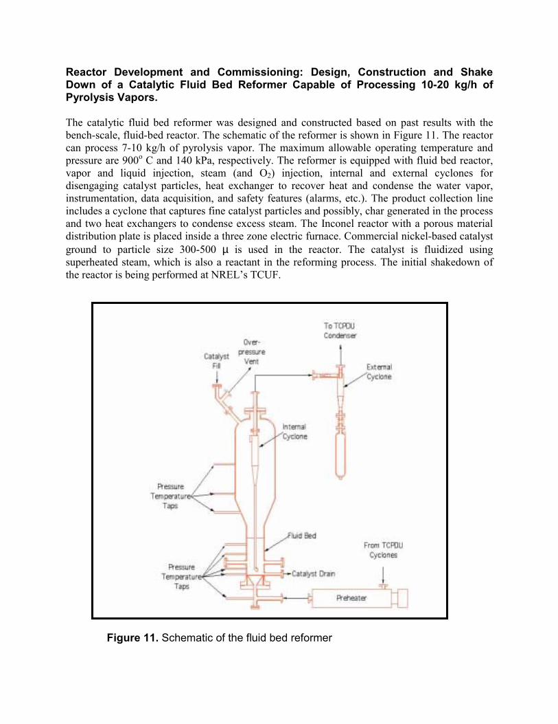
Reactor Development and Commissioning: Design, Construction and ShakeDown of a Catalytic Fluid Bed Reformer Capable of Processing 10-20 kg/h ofPyrolysis Vapors.
The catalytic fluid bed reformer was designed and constructed based on past results with thebench-scale, fluid-bed reactor. The schematic of the reformer is shown in Figure 11. The reactorcan process 7-10 kg/h of pyrolysis vapor. The maximum allowable operating temperature andpressure are 900o C and 140 kPa, respectively. The reformer is equipped with fluid bed reactor,vapor and liquid injection, steam (and O2) injection, internal and external cyclones fordisengaging catalyst particles, heat exchanger to recover heat and condense the water vapor,instrumentation, data acquisition, and safety features (alarms, etc.). The product collection lineincludes a cyclone that captures fine catalyst particles and possibly, char generated in the processand two heat exchangers to condense excess steam. The Inconel reactor with a porous materialdistribution plate is placed inside a three zone electric furnace. Commercial nickel-based catalystground to particle size 300-500 µ is used in the reactor. The catalyst is fluidized usingsuperheated steam, which is also a reactant in the reforming process. The initial shakedown ofthe reactor is being performed at NREL�s TCUF.
Figure 11. Schematic of the fluid bed reformer

For the initial runs, a commercial nickel-based catalysts from UCI is being fluidized usingsuperheated steam which serves as a reactant in the reforming process. A 10-20 kg/hr fluid bedpyrolysis unit at TCUF is able to feed the steam-reforming unit for the shakedown. The steamreforming reactor system was shipped to NREL in March 2001 and installed in April 2001. Twotons of pelletized peanut shells were shipped from Scientific Carbons to NREL for the tests. Thecatalyst, in a form suitable for fluid bed, is not commercially available and hence has beenpurchased from United Catalysts. Initial tests are monitoring catalyst fluidization and attritionunder simulated conditions. Methane reforming is being used to verify catalyst performance.Subsequent runs with pyrolysis vapors will be performed until performance matches previouswork at the bench scale.
The process conditions and description for the hydrogen reformer system are as follows:
Process ConditionsMaximum Temp: 900° C (1650û F)Maximum Pressure: 140 kPa (20 psig)
Process Gas CompositionSteam: 16 kg/hr (35 lb/hr)Hydrogen: 1.2 kg/hr (2.6 lb/hr)CO2: 14 kg/hr (31 lb/hr)CO: 1 kg/hr (2.2 lb/hr)
Description of Reformer VesselVertical Reformer Vessel (Figures 12 and 13)• Constructed entirely of Alloy 800 except for the exterior flanges.• Exterior flanges N1 and the bottom closure is 316 stainless overlaid with Alloy 800. Other
exterior flanges are 316 stainless steel.• A Carbon steel support structure with the approximate dimensions of 52� wide and long and
64� tall and painted with a high temp coating system.• External cyclone and the catch vessel are also constructed as the same materials as the
reformer vessel and includes:• A high temp ball valve is located between the external cyclone and the collection vessel.
The reformer vessel, the external cyclone and its catch vessel are designed, fabricated, inspected,tested and stamped in accordance with the ASME Boiler and Pressure Vessel Code, Section VIII,Division 1, 1198 Edition, for 20 psig at 1650°F with no corrosion allowance.
Preheater Vessel• 3� pipe size x 59� overall length circulation preheater with 1.5� class 300 flanged inlet and
outlet connections and mounting supports for horizontal mounting• Vessel fabrication of 316H stainless steel.• Three tubular heating elements sheathed in Inconel 600 and designed for operation at 240
volts a.c, 4 kW maximum.• NEMA 4 terminal housing

• Hi-Limit type K thermocouple is attached to the vessel shell and Process type Kthermocouple is located near the outlet.
• The preheater vessel is thermally insulated with 2� TR-19 insulation and two 2� layers ofCalcium Silicate insulation
• The preheater vessel was designed, fabricated, inspected, tested and stamped in accordancewith the ASME Boiler and Pressure Vessel Code, Section VIII, Division 1, 1198 Edition, for50 psig at 1450°F with no corrosion allowance.
Thermal Contact Protection• The preheater vessel, reformer vessel, external cyclone (Figure 14) and the catch vessel are
provided with insulation and/or external guarding to prevent accidental human contact withsurfaces having a temperature greater than 150° F during normal operation.
• The carbon steel support structure for the vessel provides support for the preheater vesseland ceramic wool insulation with a further covering of expanded metal.
Reactor Vessel Heaters for Section 1, 2, and 3• 2-piece, semi-cone shaped ceramic fiber heater• Dimensions are 26� inside diameter x 36� section 1; 18� inside diameter x 14.25� long for
section 2, and 12� inside diameter x 27.5� long for section 3• Designed for operation at 240 volts a.c.
Control Panel for Preheater and Reformer Heaters• As designed and built by Watlow Heaters• 56 kW, three phase• Four Watlow Din-A-Mite power controllers• Four Watlow Series F4 Process Controls with cascade software• Four Watlow Series 146 Hi-Limit Devices for over temperature protection• On / Off / Set up Control selector switch with pilot light• Hi-limit pilot lights with common reset pushbutton• Mounted in a 36� high x 24� wide x 10� deep NEMA 12 electrical enclosure with filtered
cooling fans• Controls wired and tested at Watlow factory
The above reformer system, designed by the project team, was constructed by an outsideprofessional firm through subcontracting. A photograph of the final product is shown in Figure15.

Figure 12. Vertical Reformer Vessel

Figure 13. Reactor Bottom Detail

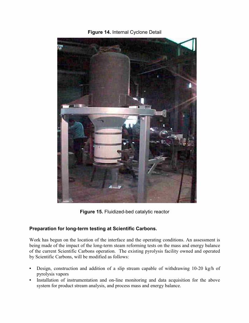
Figure 14. Internal Cyclone Detail
Figure 15. Fluidized-bed catalytic reactor
Preparation for long-term testing at Scientific Carbons.
Work has begun on the location of the interface and the operating conditions. An assessment isbeing made of the impact of the long-term steam reforming tests on the mass and energy balanceof the current Scientific Carbons operation. The existing pyrolysis facility owned and operatedby Scientific Carbons, will be modified as follows:
• Design, construction and addition of a slip stream capable of withdrawing 10-20 kg/h ofpyrolysis vapors
• Installation of instrumentation and on-line monitoring and data acquisition for the abovesystem for product stream analysis, and process mass and energy balance.

The operation of the system at the Scientific Carbons Inc. site will not occur in Phase 1, butwould begin in the second year under a Phase 2 project. We have prepared the necessaryanalytical systems to monitor the transportation system performance.
Preparation for Hydrogen Storage and Utilization
We have begun analysis of how storage will be accomplished on the Scientific Carbons site. Pastapproaches to the storage of hydrogen in mixtures with compressed natural gas are beingreviewed and calculation of mixture limits are being made. Other storage options are beingexplored that will meet the needs of the planned demonstration. Model system testing will beperformed. The design of a storage system is being done and include:
• Pressure Swing Absorption (PSA) system for the purification of hydrogen and the separationof CO2
• Holding tank (or another device) for H2 storage• Compression station to charge the H2 into blends with CNG• Instrumentation and on-line monitoring and data acquisition for the above system
In preparation for hydrogen utilization, our activities in Phase 1 have included identifying thecommunity partner and working with that partner to define the transportation fleet application.The utilization system design will then occur including modification to a refueling station andthe vehicle(s). Up to 30% of hydrogen by volume could be stored in this way and hence theblend would enable the hydrogen produced to be used in a convectional CNG bus without majormodifications. To simplify the start up of the project, the system would begin with commercialsources of hydrogen.
Environmental and Technical Evaluation
An important part of the decision to implement a hydrogen transportation technology will bedocumentation and evaluation of benefits and system performance. We have begun thisevaluation in conjunction with the planning of the bus demonstration.
Partnership Building and Outreach
We coordinated the fuel utilization demonstration by working with a local municipality tooperate a vehicle, such as a transit bus, under normal operation. Work has begun with localparties to participate in the transportation demonstration. We have received a letter of interest inaccepting partnership role from Albany State University (ASU) to host the hydrogen busdemonstration in the city of Albany Georgia. Albany Water, Gas & Light Commission, amunicipally owned utility, has expressed interest in the use of renewable hydrogen for powergeneration. Initial meetings with Dougherty County officials to propose a non-operational rolewere held and they are interested in participating. Collaboration with researchers and modelers atJPL was initiated. In addition, close cooperation with other related projects at NREL and JPL isconstantly maintained. A special interest among the partners is the identification of other co-roduct options for expanded deployment opportunities. Emissions monitoring will be performedto assess the environmental impact of the hydrogen blend. A social acceptability study will be

performed to assess how the community views the benefits and risks of this new technology.
Future Work
The approach for the next stage is to address the remaining engineering research anddevelopment questions related to the conversion of pyrolysis vapors and/or bio-oil to hydrogen,so that a demonstration of the overall concept of biomass to hydrogen can be successful. The useof bio-oils derived from slow pyrolysis of biomass in a reforming operation and the directcoupling of vapors from pyrolysis to steam reforming have not been previously attempted.Process research is required to identify the best operating conditions. Catalyst performance andlifetime will be assessed and data collected on catalyst regeneration. this information will beused in the development of the catalyst regenerator. The other tasks will continue to focus onfeedstocks, hydrogen storage options, fuel utilization and partnership development, and areessential to the development of a demonstration of the technology. This will allow commercialevaluations of the concept to be made.
Specific future work and milestones include: gather data for estimating model parameters andrun logistical model for Georgia with peanuts as feedstock; quantify importance of transportationcosts in biomass processing and identify other biomass feedstocks available in Georgia; performexperiments of liquid-liquid equilibrium on representative compounds found in bio-oils; setup,shakedown and operate continuously reactor at Scientific Carbons site; design hydrogen storageand utilization system for transportation demonstration; cost-effective local bus demonstration onhydrogen utilization; develop a fuel cell based hydrogen utilization effort with the Albany Water,Gas & Light Commission; establish additional non-operational partners in Y2 (2001/2002) & Y3(2002/2003); and incorporate hydrogen technology in student training and education at ClarkAtlanta University.
Conclusions
Biomass as a product of photosynthesis is a renewable resource that can be used for sustainableproduction of hydrogen. However, direct production of hydrogen from biomass bygasification/water-gas shift technology is unfavorable economically, except for very low costfeedstocks and very large plants. Our approach proposes an alternative strategy with potentiallybetter economics resulting from combined production of hydrogen with valuable co-products.The concept is based on a two-stage process: slow pyrolysis of biomass to generate activatedcarbon and bio-oil, and catalytic steam reforming of the oil or its fractions to produce hydrogen.The design and utilization of the fluid-bed reformer was completed and shakedown of the reactoris to be completed by Summer 2001. Phase 2 of the project will focus on the long term catalysttesting at Scientific Carbons.
References
1. The Green Hydrogen Report: The 1995 Progress Report of the Secretary of Energy�sHydrogen Technical Advisory Panel, May 1995, DOE/GO-10095-179 DE95009213.
2. Wang, D., S. Czernik, D. Montané, M. Mann, and E. Chornet, 1997, I&EC Research, 36,1507-1518.

3. Wang, D., S. Czernik, and E. Chornet, 1998, �Production of Hydrogen from Biomass byCatalytic Steam Reforming of Fast Pyrolysis Oil�, Energy&Fuels, 12, 19-24.
4. Mann, M.K. 1995. �Technical and economic analyses of hydrogen production via indirectlyheated gasification and pyrolysis,� in Proceedings of the 1995 Hydrogen Program Review, Vol.1, NREL/CP-430-20036-Vol. 1, pp. 205-236.
5. Wang, D., D. Montané, E. Chornet, 1996, �Catalytic Steam Reforming of Biomass-DerivedOxygenates: Acetic Acid and Hydroxyacetaldehyde�, J. Appl. Catal. A: General, 143, 245-270.
6. Czernik, S., D. Wang, D. Montané, E. Chornet, 1997, �Catalytic Steam Reforming ofBiomass-Derived Fractions from Pyrolysis Processes. Developments in ThermochemicalBiomass Conversion�, Eds. Bridgwater, A.V. and Boocock, D.G.B., Blackie Academic &Professional, pp.672-686.
7. Goldstein, Irving S., 2000, �Composition of Biomass.� Organic Chemicals from Biomass.Boca Raton: CRC Press.
8. Milne, T., et al. �A Review of the Chemical Composition of Fast-Pyrolysis Oils fromBiomass.� Notes from the NREL, Center for Renewable Chemical Technologies and Materials.
9. Roy, et al. U.S. Patent 6,143,856., 2000, �Process for the production of phenolic-richpyrolysis oils for use in making phenol-formaldehyde resole resins.� .
10. Piskorz, J., et al., 1998, �Composition of Oils Obtained by Fast Pyrolysis of DifferentWoods.� Pyrolysis Oils from Biomass: Producing, Analyzing, and Upgrading. Washington,D.C.: American Chemical Society.
11. Packdel, H. & Roy, Christian., 1998, �Chemical Characterization of Wood Pyrolysis OilsObtained in a Vacuum-Pyrolysis Multiple-Hearth Reactor.� Pyrolysis Oils from Biomass:Producing, Analyzing, and Upgrading. Washington, D.C.: American Chemical Society.
12. Love, Robert F., Morris, James G., and Wesolowsky, George O., 1988, Facilities Location:Models & Methods, North Holland, New York.
13. Angus-Hankin, C., Stokes, B., and Twaddle, A., 1995, �The Transportation of Fuel Woodfrom Forest to Facility,� Biomass and Bioenergy v. 9(1-5) p. 191-203.
14. Nilsson, D., 1999, �SHAM---a simulation model for designing straw fuel delivery systems.Part 2: model applications,� Biomass and Bioenergy v.16, p. 39-50.
15. Gomes, Raquel S., Wilson, Paul N., Coates Wayne E., and Fox, Roger W., 1997, �Cotton(Gossypium) plant residue for industrial fuel. An economic assessment,� Industrial Crops andProducts v. 7, p. 1-8.
Related Documents