An Improved Two-Vector Model Predictive Torque Control based on RMS Duty Ratio Optimization for PMSM Chenwei Ma Department of Electrical Energy, Metals, Mechanical Constructions & Systems Ghent University EEDT-Decision and Control Flanders Make Ghent, Belgium Institute of Electrical Engineering Harbin Engineering University Harbin, China [email protected] Xuliang Yao Institute of Electrical Engineering Harbin Engineering University Harbin, China [email protected] Huayu Li Department of Electrical Energy, Metals, Mechanical Constructions & Systems Ghent University EEDT-Decision and Control Flanders Make Ghent, Belgium [email protected] Frederik De Belie Department of Electrical Energy, Metals, Mechanical Constructions & Systems Ghent University EEDT-Decision and Control Flanders Make Ghent, Belgium [email protected] Abstract—This paper proposes an improved two-vector model- predictive torque control (MPTC) strategy to reduce the average torque ripple and improve the flux tracking performance. When determining the duty ratio of vector combination, this method aims at restricting the root mean square (RMS) error of both torque and flux during the whole control period. Every vector combination and corresponding time duration are evaluated in the cost function, which leads to global restriction of torque ripple and flux ripple. In order to avoid increasing switching frequency and computational burden, a restriction is added on the second vector. The three candidates of the second vector are the two adjacent vectors of the first one and zero vector. Simulation results are provided to show the effectiveness of the proposed strategy. Keywords—Permanent magnet synchronous motor, predictive control, root mean square, torque and flux ripple I. INTRODUCTION Permanent magnet synchronous machines (PMSMs) with advantages of high efficiency, high torque density and good dynamic performance, have been employed in many industrial areas [1-3]. Direct torque control (DTC) is one of the most popular control strategies for PMSM due to its fast dynamic response and simple structure [4]. However, the main drawbacks of DTC are high torque ripple and high flux ripple [5-6]. In recent years, finite-control-set model predictive torque control (FCS-MPTC), which is considered as an alternative control strategy to DTC has been widely researched. It takes the advantage of the inherent discrete nature of power converters, predicts the future state of the system and select the optimal voltage vector which can minimize a predefined cost function [7-9]. In spite of advantages above, torque ripple and flux ripple are still inevitable for MPTC, since only one vector is selected during a fixed full control period. Recently, several researches aiming at reducing torque ripple of MPTC have been conducted. In [10], a tolerance band is set to restrict the torque. In one control period, an active vector is first selected based on the cost function. When the torque reaches the boundary of the tolerance band under the active vector, zero vector is applied for the rest of the control period. However, zero vector may not be the best choice for the second vector. In [11] and [12], the switching instant is determined based on solving optimization problem, instead of the torque boundary. Although the torque ripple is reduced, this method failed to take the duration of the active vector into consideration when determining the optimal vector, since the duration of the vector is modified when hitting the boundary. Authors of [13] propose a generalized two-vector-based MPTC method. In this method, the restriction of the second vector is released from zero vector to arbitrary vector. It means that 7h7=49 voltage vector combinations can be selected, which provides more possibilities to reduce torque ripple. However, the computational burden is remarkably increased. In addition, when determining the duration of the first vector, only the instantaneous minimum torque error at the end of the control period is considered, namely deadbeat (DB) control. It cannot guarantee that the mean torque ripple and the flux ripple are all reduced during the whole control period. In this paper, an improved two-vector MPTC with root mean square (RMS) error duty ratio optimization for PMSM is proposed. This strategy utilizes two vectors in one control period to improve the steady state performance and eliminate the current harmonic. Meanwhile, a principle of RMS error is utilized when determining the duty ratio. It can restrict the average torque and flux error over the whole control period. Besides, better flux tracking performance can be reached. In this strategy, duty ratio is calculated for every vector combination before selection. It guarantees the optimal vector combination with corresponding duration can be selected when evaluating the cost function. Furthermore, to reach a balance among switching frequency, computational burden and steady state performance, a restriction is set on the second vector. Two adjacent vectors of brought to you by CORE View metadata, citation and similar papers at core.ac.uk provided by Ghent University Academic Bibliography

Welcome message from author
This document is posted to help you gain knowledge. Please leave a comment to let me know what you think about it! Share it to your friends and learn new things together.
Transcript
An Improved Two-Vector Model Predictive Torque
Control based on RMS Duty Ratio Optimization for
PMSM
Chenwei Ma
Department of Electrical Energy,
Metals, Mechanical
Constructions & Systems
Ghent University
EEDT-Decision and Control
Flanders Make
Ghent, Belgium
Institute of Electrical Engineering
Harbin Engineering University
Harbin, China
Xuliang Yao
Institute of Electrical Engineering
Harbin Engineering University
Harbin, China
Huayu Li
Department of Electrical Energy,
Metals, Mechanical
Constructions & Systems
Ghent University
EEDT-Decision and Control
Flanders Make
Ghent, Belgium
Frederik De Belie
Department of Electrical Energy,
Metals, Mechanical
Constructions & Systems
Ghent University
EEDT-Decision and Control
Flanders Make
Ghent, Belgium
Abstract—This paper proposes an improved two-vector model-
predictive torque control (MPTC) strategy to reduce the average
torque ripple and improve the flux tracking performance. When
determining the duty ratio of vector combination, this method
aims at restricting the root mean square (RMS) error of both
torque and flux during the whole control period. Every vector
combination and corresponding time duration are evaluated in the
cost function, which leads to global restriction of torque ripple and
flux ripple. In order to avoid increasing switching frequency and
computational burden, a restriction is added on the second vector.
The three candidates of the second vector are the two adjacent
vectors of the first one and zero vector. Simulation results are
provided to show the effectiveness of the proposed strategy.
Keywords—Permanent magnet synchronous motor, predictive
control, root mean square, torque and flux ripple
I. INTRODUCTION
Permanent magnet synchronous machines (PMSMs) with advantages of high efficiency, high torque density and good dynamic performance, have been employed in many industrial areas [1-3]. Direct torque control (DTC) is one of the most popular control strategies for PMSM due to its fast dynamic response and simple structure [4]. However, the main drawbacks of DTC are high torque ripple and high flux ripple [5-6]. In recent years, finite-control-set model predictive torque control (FCS-MPTC), which is considered as an alternative control strategy to DTC has been widely researched. It takes the advantage of the inherent discrete nature of power converters, predicts the future state of the system and select the optimal voltage vector which can minimize a predefined cost function [7-9]. In spite of advantages above, torque ripple and flux ripple are still inevitable for MPTC, since only one vector is selected during a fixed full control period.
Recently, several researches aiming at reducing torque ripple of MPTC have been conducted. In [10], a tolerance band is set
to restrict the torque. In one control period, an active vector is first selected based on the cost function. When the torque reaches the boundary of the tolerance band under the active vector, zero vector is applied for the rest of the control period. However, zero vector may not be the best choice for the second vector. In [11] and [12], the switching instant is determined based on solving optimization problem, instead of the torque boundary. Although the torque ripple is reduced, this method failed to take the duration of the active vector into consideration when determining the optimal vector, since the duration of the vector is modified when hitting the boundary. Authors of [13] propose a generalized two-vector-based MPTC method. In this method, the restriction of the second vector is released from zero
vector to arbitrary vector. It means that 7 7=49 voltage vector combinations can be selected, which provides more possibilities to reduce torque ripple. However, the computational burden is remarkably increased. In addition, when determining the duration of the first vector, only the instantaneous minimum torque error at the end of the control period is considered, namely deadbeat (DB) control. It cannot guarantee that the mean torque ripple and the flux ripple are all reduced during the whole control period.
In this paper, an improved two-vector MPTC with root mean square (RMS) error duty ratio optimization for PMSM is proposed. This strategy utilizes two vectors in one control period to improve the steady state performance and eliminate the current harmonic. Meanwhile, a principle of RMS error is utilized when determining the duty ratio. It can restrict the average torque and flux error over the whole control period. Besides, better flux tracking performance can be reached. In this strategy, duty ratio is calculated for every vector combination before selection. It guarantees the optimal vector combination with corresponding duration can be selected when evaluating the cost function. Furthermore, to reach a balance among switching frequency, computational burden and steady state performance, a restriction is set on the second vector. Two adjacent vectors of
brought to you by COREView metadata, citation and similar papers at core.ac.uk
provided by Ghent University Academic Bibliography
the first vector and zero vector are regarded as the candidates for the second vector. The simulation results show that better steady state performance are achieved in the proposed strategy compared with the conventional FCS-MPTC and the conventional two-vector MPTC method.
II. MODEL OF PMSM AND INVERTER
To analyze the MPTC strategy, this paper uses the rotary reference frame. Hence, the equations of surface mounted
PMSM ( d q sL L L= = ) in d-q reference frame can be described
as follows:
sd
sd s sd r sq
dV R I
dt
yw y= + - (1)
sq
sq s sq r sd
dV R I
dt
yw y= + + (2)
sd s sd fL Iy y= + (3)
sq s sqL Iy = (4)
3
2e f sqT p Iy= (5)
where sdV and sqV are d-axis and q-axis stator voltage
respectively, sdy and sqy are d-axis and q-axis stator flux
respectively, sdI and sqI are d-axis and q-axis stator current
respectively, eT is electromagnetic torque, p is the number of
pole pairs, sR is stator resistance, sL is inductance, rw is electrical
rotor speed, fy is permanent magnet flux linkage.
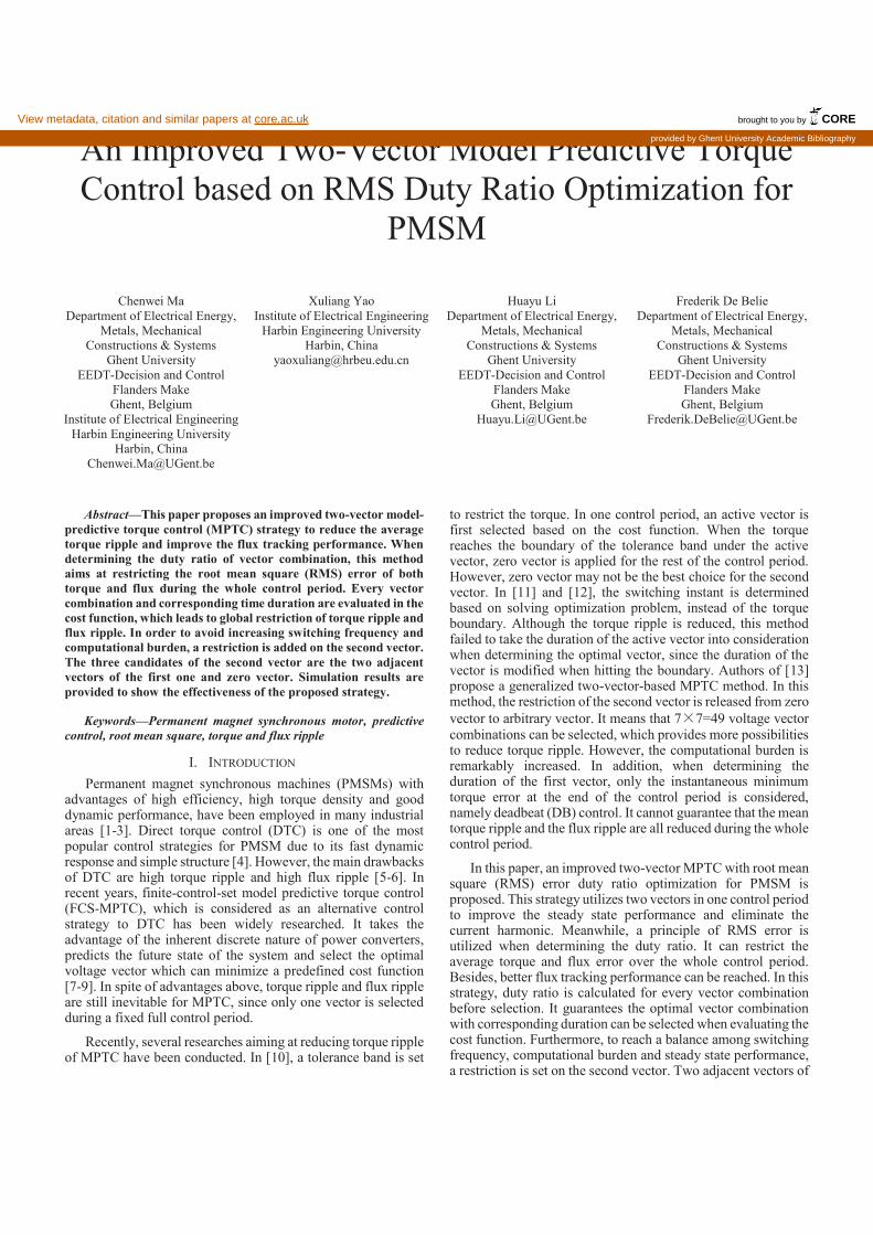
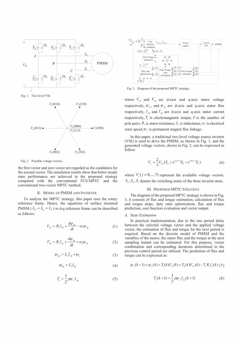
In this paper, a traditional two-level voltage source inverter (VSI) is used to drive the PMSM, as shown in Fig. 1, and the generated voltage vectors, shown in Fig. 2, can be expressed as follow:
2 /3 4 /32( )
3
i i
j dc a b cV V S e S e Sp p= + + (6)
where ( 0,...,7)jV j = represent the available voltage vectors,
, ,a b cS S S denote the switching states of the three inverter arms.
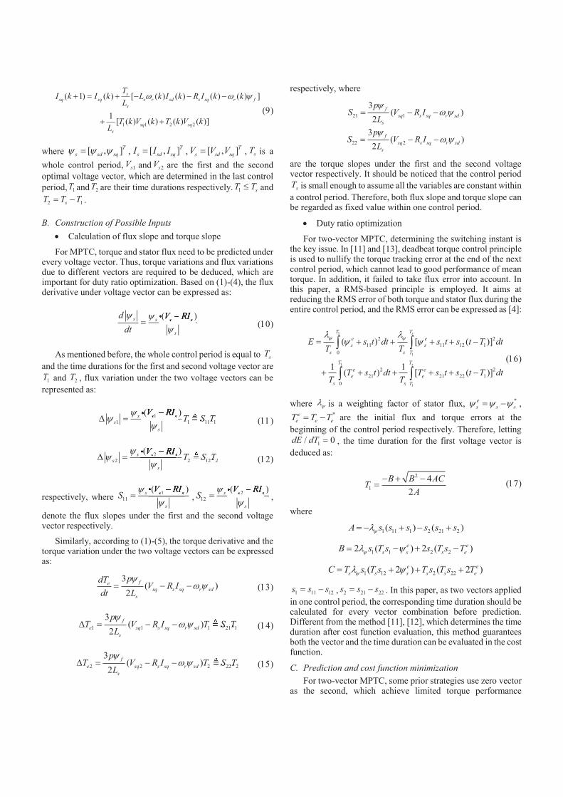
III. PROPOSED MPTC STRATEGY
The diagram of the proposed MPTC strategy is shown in Fig. 3, it consists of flux and torque estimation, calculation of flux and torque slope, duty ratio optimization, flux and torque prediction, cost function evaluation and vector output.
A. State Estimation
In practical implementation, due to the one period delay between the selected voltage vector and the applied voltage vector, the estimation of flux and torque for the next period is required. Based on the discrete model of PMSM and the variables of the motor, the stator flux and the torque at the next sampling instant can be estimated. For this purpose, vector combination and corresponding durations determined in the previous control period are utilized. The prediction of flux and torque can be expressed as:
1 1 2 2( 1) ( ) ( ) ( ) ( ) ( ) ( )s s s s s s sk k T k V k T k V k T R I ky y+ = + + - (7)
3
( 1) ( 1)2
e f sqT k p I ky+ = + (8)
+
-
Vdc
D1 D3 D5
D2D6D4
A
B
C
IA
IB
IC
aS
aS
bS cS
bS cS
PMSM
Fig. 1. Two level VSI.
1(100)V
2(110)V3(010)V
4(011)V
5(001)V 6 (101)V
0(000)V
7 (111)V
Fig. 2. Possible voltage vectors.
2-level
VSI
Vector
output
Flux/Torque
estimation
PMSM
( )sV k
( )sI k
( )r kw
Flux/Torque
slop
calculation
( 1)eT k +( 1)s ky +
Duty raio
optimization
11 12,S S
21 22,S S
*
eT*
sy
Flux/Torque
prediction
, ,,i j i jV T
Cost
function
evaluation
( 2)eT k + ( 2)s ky +
1,2 1,2,opt optV TPI
*
eT
*
sy-rw
*
rw
( 1)sqI k +
Fig. 3. Diagram of the proposed MPTC strategy.
1 1 2 2
( 1) ( ) [ ( ) ( ) ( ) ( ) ]
1[ ( ) ( ) ( ) ( )]
s
sq sq s r sd s sq r f
s
sq sq
s
TI k I k L k I k R I k k
L
T k V k T k V kL
w w y+ = + - - -
+ + (9)
where [ , ]T
s sd sqy y y= , [ , ]T
s sd sqI I I= , [ , ]T
s sd sqV V V= , sT is a
whole control period, 1sV and 2sV are the first and the second
optimal voltage vector, which are determined in the last control
period, 1T and 2T are their time durations respectively. 1 sT T£ and
2 1sT T T= - .
B. Construction of Possible Inputs
· Calculation of flux slope and torque slope
For MPTC, torque and stator flux need to be predicted under every voltage vector. Thus, torque variations and flux variations due to different vectors are required to be deduced, which are important for duty ratio optimization. Based on (1)-(4), the flux derivative under voltage vector can be expressed as:
( )s s s s
s
d V RI
dt
y yy
-=
( )s s s( )( )( )( )( )( )( )( )( ) (10)
As mentioned before, the whole control period is equal to sT
and the time durations for the first and second voltage vector are
1T and 2T , flux variation under the two voltage vectors can be
represented as:
1
1 1 11 1
( )s s s
s
s
V RIT S T
yy
y-
D =1 1 11
( )s s s1( )( )1( )( )1( )( )( )1( )( )1 1 11 1T S T1 1 11 11 1 11 (11)
2
2 2 12 2
( )s s s
s
s
V RIT S T
yy
y-
D =2 2 12
( )s s s2( )( )2( )( )2( )( )( )2( )( )2 2 12 2T S T2 2 12 22 2 12 2 (12)
respectively, where 1
11
( )s s s
s
V RIS
yy
-=
( )s s s1( )( )1( )( )1( )( )( )1( )( ),
2
12
( )s s s
s
V RIS
yy
-=
( )s s s2( )( )2( )( )2( )( )( )2( )( ),
denote the flux slopes under the first and the second voltage vector respectively.
Similarly, according to (1)-(5), the torque derivative and the torque variation under the two voltage vectors can be expressed as:
3
( )2
fe
sq s sq r sd
s
pdTV R I
dt L
yw y= - - (13)
1 1 1 21 1
3( )
2
f
e sq s sq r sd
s
pT V R I T S T
L
yw yD = - -1 1 1 21 1T S T1 1 1 21 11 1 1 21 1 (14)
2 2 2 22 2
3( )
2
f
e sq s sq r sd
s
pT V R I T S T
L
yw yD = - -2 2 2 22 2T S T2 2 2 22 22 2 2 22 2 (15)
respectively, where
21 1
3( )
2
f
sq s sq r sd
s
pS V R I
L
yw y= - -
22 2
3( )
2
f
sq s sq r sd
s
pS V R I
L
yw y= - -
are the torque slopes under the first and the second voltage vector respectively. It should be noticed that the control period
sT is small enough to assume all the variables are constant within
a control period. Therefore, both flux slope and torque slope can be regarded as fixed value within one control period.
· Duty ratio optimization
For two-vector MPTC, determining the switching instant is the key issue. In [11] and [13], deadbeat torque control principle is used to nullify the torque tracking error at the end of the next control period, which cannot lead to good performance of mean torque. In addition, it failed to take flux error into account. In this paper, a RMS-based principle is employed. It aims at reducing the RMS error of both torque and stator flux during the entire control period, and the RMS error can be expressed as [4]:
1
1
1
1
2 2
11 11 12 1
0
2 2
21 21 22 1
0
( ) [ ( )]
1 1( ) [ ( )]
s
s
TT
e e
s s
s s T
TT
e e
e e
s s T
E s t dt s t s t T dtT T
T s t dt T s t s t T dtT T
y yl ly y= + + + + -
+ + + + + -
ò ò
ò ò (16)
where yl is a weighting factor of stator flux, *e
s s sy y y= - ,*e
e e eT T T= - are the initial flux and torque errors at the
beginning of the control period respectively. Therefore, letting
1/ 0dE dT = , the time duration for the first voltage vector is
deduced as:
2
1
4
2
B B ACT
A
- + -= (17)
where
1 11 1 2 21 2( ) ( )A s s s s s syl= - + - +
1 1 2 22 ( ) 2 ( )e e
s s s eB s T s s T s Tyl y= - + -
1 12 2 22( 2 ) ( 2 )e e
s s s s s eC T s T s T s T s Tyl y= + + +
1 11 12s s s= - , 2 21 22s s s= - . In this paper, as two vectors applied
in one control period, the corresponding time duration should be calculated for every vector combination before prediction. Different from the method [11], [12], which determines the time duration after cost function evaluation, this method guarantees both the vector and the time duration can be evaluated in the cost function.
C. Prediction and cost function minimization
For two-vector MPTC, some prior strategies use zero vector as the second, which achieve limited torque performance
improvement, since zero vector may not be the optimal one for the second vector. Conversely, some strategies select the second vector from all the seven voltage vectors, which leads to high switching frequency and increasing computational burden. To reach a balance, this paper uses an active vector as the first vector. For the second vector, the two adjacent vectors of the first one and zero vector are considered as the candidates. Thus,
6 3=18 vectors combinations are provided.
Based on the estimations and the calculated time duration for the (k+1)th control period, flux and torque at the (k+2)th sampling instant under all vector combinations can be predicted as:
| 1 1|
2 2|
( 2) ( 1) ( 1) ( 1)
( 1) ( 1) ( 1)
s n s s i
s j s s s
k k T k V k
T k V k T R I k
y y+ = + + + +
+ + + - + (18)
| |
3( 2) ( 2)
2e n f sq nT k p I ky+ = + (19)
|
1 1| 2 2|
( 2) [ ( 1) ( 1) ( 1) ( 1) ]
1[ ( 1) ( 1) ( 1) ( 1)] ( 1)
s
sq n s r sd s sq r f
s
sq i sq j sq
s
TI k L k I k R I k k
L
T k V k T k V k I kL
w w y+ = - + + - + - +
+ + + + + + + + (20)
where 1,2,...,18n = , represents the number of the vector
combination, 1,2,...,6i = is the number of the first vector,
1, 1,0j i i= - + , is the number of the second vector. The vector
combination, which can minimize a cost function will be selected as the optimal vector combination and applied in next control period. In this paper, to be coincident with the duty ratio optimization principle, the cost function is expressed as:
* 2 * 2[ ( 2)] [ ( 2) ]e e s sg T T k k ky y y= - + + - + (21)
where ky is the weight coefficient of stator flux.
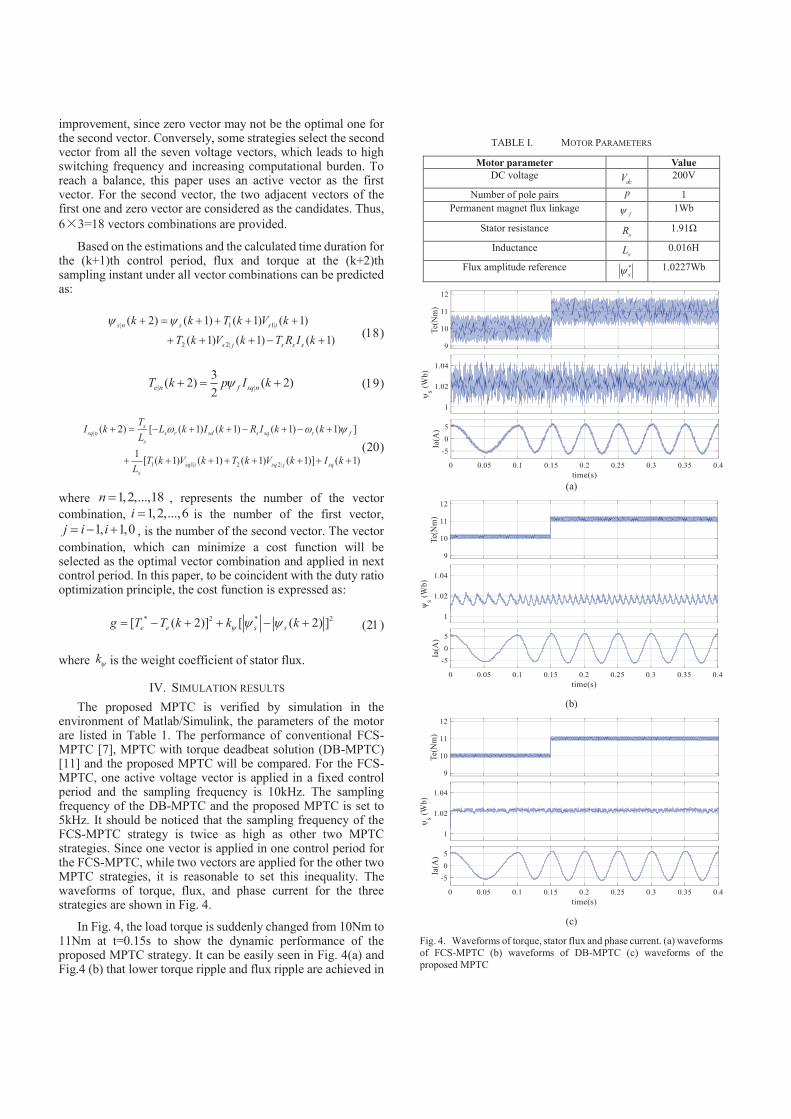
IV. SIMULATION RESULTS
The proposed MPTC is verified by simulation in the environment of Matlab/Simulink, the parameters of the motor are listed in Table 1. The performance of conventional FCS-MPTC [7], MPTC with torque deadbeat solution (DB-MPTC) [11] and the proposed MPTC will be compared. For the FCS-MPTC, one active voltage vector is applied in a fixed control period and the sampling frequency is 10kHz. The sampling frequency of the DB-MPTC and the proposed MPTC is set to 5kHz. It should be noticed that the sampling frequency of the FCS-MPTC strategy is twice as high as other two MPTC strategies. Since one vector is applied in one control period for the FCS-MPTC, while two vectors are applied for the other two MPTC strategies, it is reasonable to set this inequality. The waveforms of torque, flux, and phase current for the three strategies are shown in Fig. 4.
In Fig. 4, the load torque is suddenly changed from 10Nm to 11Nm at t=0.15s to show the dynamic performance of the proposed MPTC strategy. It can be easily seen in Fig. 4(a) and Fig.4 (b) that lower torque ripple and flux ripple are achieved in
TABLE I. MOTOR PARAMETERS
Motor parameter Value
DC voltage dcV 200V
Number of pole pairs p 1
Permanent magnet flux linkage fy 1Wb
Stator resistance sR 1.91Ω
Inductance sL 0.016H
Flux amplitude reference *
sy 1.0227Wb
(a)
(b)
(c)
Fig. 4. Waveforms of torque, stator flux and phase current. (a) waveforms
of FCS-MPTC (b) waveforms of DB-MPTC (c) waveforms of the
proposed MPTC
DB-MPTC than that in FCS-MPTC. However, since torque deadbeat solution is utilized, the torque of DB-MPTC can only reach the reference value at the end of every control period. For the proposed MPTC, an improved flux and torque RMS solution is employed. Hence, the torque error can be minimized during the whole control period, which can be easily seen in Fig.4 (c). Furthermore, it can be seen in Fig. 4(b) that DB-MPTC has bad performance in flux tracking, because it selects the active vector before duty ratio optimization. Meanwhile, the deadbeat solution does not consider the flux ripple when determining the duty ratio. Conversely, the proposed MPTC calculates the duty ratio for all possible vector combinations before cost function evaluation with taking the flux error into account. Therefore, the proposed MPTC achieves good performance of flux tracking, as shown in Fig. 4(c).
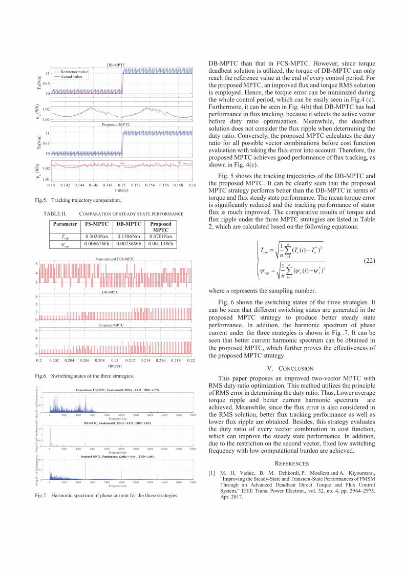
Fig. 5 shows the tracking trajectories of the DB-MPTC and the proposed MPTC. It can be clearly seen that the proposed MPTC strategy performs better than the DB-MPTC in terms of torque and flux steady state performance. The mean torque error is significantly reduced and the tracking performance of stator flux is much improved. The comparative results of torque and flux ripple under the three MPTC strategies are listed in Table 2, which are calculated based on the following equations:
* 2
1
* 2
1
1( ( ) )
1( ( ) )
n
rip e e
i
n
rip s s
i
T T i Tn
in
y y y
=
=
ì= -ï
ïíï = -ïî
å
å (22)
where n represents the sampling number.
Fig. 6 shows the switching states of the three strategies. It
can be seen that different switching states are generated in the
proposed MPTC strategy to produce better steady state
performance. In addition, the harmonic spectrum of phase
current under the three strategies is shown in Fig .7. It can be
seen that better current harmonic spectrum can be obtained in
the proposed MPTC, which further proves the effectiveness of
the proposed MPTC strategy.
V. CONCLUSION
This paper proposes an improved two-vector MPTC with RMS duty ratio optimization. This method utilizes the principle of RMS error in determining the duty ratio. Thus, Lower average torque ripple and better current harmonic spectrum are achieved. Meanwhile, since the flux error is also considered in the RMS solution, better flux tracking performance as well as lower flux ripple are obtained. Besides, this strategy evaluates the duty ratio of every vector combination in cost function, which can improve the steady state performance. In addition, due to the restriction on the second vector, fixed low switching frequency with low computational burden are achieved.
REFERENCES
[1] M. H. Vafaie, B. M. Dehkordi, P. Moallem and A. Kiyoumarsi, “Improving the Steady-State and Transient-State Performances of PMSM Through an Advanced Deadbeat Direct Torque and Flux Control System,” IEEE Trans. Power Electron., vol. 32, no. 4, pp. 2964–2975, Apr. 2017.
DB-MPTC
Proposed-MPTC
Reference value
Actual value
Fig.5. Tracking trajectory comparation.
TABLE II. COMPARATION OF STEADY STATE PERFORMANCE
Parameter FS-MPTC DB-MPTC Proposed
MPTC
Trip 0.3024Nm 0.1386Nm 0.0701Nm
ψrip
0.00667Wb 0.00736Wb 0.00113Wb
Conventional FCS-MPTC
DB-MPTC
Proposed-MPTC
Fig.6. Switching states of the three strategies.
Fig.7. Harmonic spectrum of phase current for the three strategies.

[2] Y. Zhang, D. Xu, and L. Huang, “Generalized Multiple-Vector-Based Model Predictive Control for PMSM Drives,” IEEE Trans. Ind. Electron., vol. 65, no. 12, pp. 9356-9366, 2018.
[3] P. Kakosimos and H. Abu-Rub, “Predictive Speed Control With Short Prediction Horizon for Permanent Magnet Synchronous Motor Drives,” IEEE Trans. Power Electron., vol. 33, no. 3, pp. 2740-2750, 2018.
[4] F. Niu, K. Li, and Y. Wang, “Direct Torque Control for Permanent-Magnet Synchronous Machines Based on Duty Ratio Modulation,” IEEE Trans. Ind. Electron., vol. 62, no. 10, pp. 6160–6170, Oct. 2015.
[5] Y. Wang, X. Wang, W. Xie, F. Wang, M. Dou, R. M. Kennel, et al., “Deadbeat Model-Predictive Torque Control With Discrete Space-Vector Modulation for PMSM Drives,” IEEE Trans. Ind. Electron., vol. 64, no. 5, pp. 3537–3547, May 2017.
[6] Y. Cho, Y. Bak, and K.-B. Lee, “Torque-Ripple Reduction and Fast Torque Response Strategy for Predictive Torque Control of Induction Motors,” IEEE Trans. Power Electron., vol. 33, no. 3, pp. 2458-2470, 2018.
[7] H. Miranda, P. Cortes, J. Yuz, and J. Rodriguez, “Predictive torque control of induction machines based on state-space models,” IEEE Trans. Ind. Electron., vol. 56, no. 6, pp. 1916–1924, Jun. 2009.
[8] M. Siami, D. Arab Khaburi, and J. Rodriguez, “Simplified Finite Control Set-Model Predictive Control for Matrix Converter-Fed PMSM Drives,” IEEE Trans. Power Electron., vol. 33, no. 3, pp. 2438-2446, 2018.
[9] M. Amiri, J. Milimonfared, and D. A. Khaburi, “Predictive Torque Control Implementation for Induction Motors Based on Discrete Space Vector Modulation,” IEEE Trans. Ind. Electron., vol. 65, no. 9, pp. 6881-6889, 2018.
[10] M. Pacas and J. Weber, “Predictive direct torque control for the PM synchronous machine,” IEEE Trans. Ind. Electron., vol. 52, no. 5,pp. 1350–1356, Oct. 2005.
[11] Y. Xu, Q. Zhou and B. Zhang, “A Model Predictive Torque Control Strategy of PMSM with Torque Deadbeat Duty Cycle Control,” IEEE Int. Power. Elec., 2016, pp. 782-785.
[12] Y. Zhang and H.Yang, “Torque ripple reduction of model predictive torque control of induction motor drives,” in Proc. IEEE Energy Convers. Congr.Expo., 2013, pp. 1176–1183.
[13] Y. Zhang, and H. Yang, “Generalized Two-Vector-Based Model-Predictive Torque Control of Induction Motor Drives,” IEEE Trans. Power Electron., vol. 30, no. 7, pp. 3818–3829, Jul. 2015.
Related Documents