Progress In Electromagnetics Research B, Vol. 49, 389–409, 2013 AN IMPROVED ANALYTICAL MODEL FOR SALIENT POLE SYNCHRONOUS MACHINES UNDER GENERAL ECCENTRICITY FAULT Hamidreza Akbari * Department of Electrical Engineering, Yazd Branch, Islamic Azad University, Yazd, Iran Abstract—This paper develops a more precise analytical model for calculating salient pole synchronous machine (SPSM) inductances in case of general eccentricity including static, dynamic and mixed eccentricities. The developed method is based on the modified winding function approach (MWFA) which accurately considers variable air gap function and leads to pure analytical expressions of inductances. Available analytical techniques, based on MWFA, approximate the air gap function and simplify the geometrical model of SPSM, whereas, in this study, the influence of the openings between the rotor salient poles has been taken into account by using an effective form of rotor pole shoes. Using this technique, flux fringing effect is considered. By taking into account machine geometry, type of windings connection and flux fringing effect, this method is able to model most of the important features of an eccentric SPSM. The developed analytical expressions can calculate time varying inductances of SPSMs with any eccentricity type and degree in the frame of a single program. Simulation results for static eccentricity are compared with experimental tests on a laboratory generator to verify accuracy of the proposed model. 1. INTRODUCTION To model electrical machines under different types of faults, winding function approach (WFA) [1] and finite element method (FEM) [2] have been introduced as appropriate modeling methods. Although FEM provides precise modeling, its application is complicated and time consuming especially for the analysis of electrical machines with asymmetry in the motor body such as eccentricity [2, 3]. Received 1 January 2013, Accepted 5 March 2013, Scheduled 7 March 2013 * Corresponding author: Hamidreza Akbari (hamid r [email protected]).

Welcome message from author
This document is posted to help you gain knowledge. Please leave a comment to let me know what you think about it! Share it to your friends and learn new things together.
Transcript

Progress In Electromagnetics Research B, Vol. 49, 389–409, 2013
AN IMPROVED ANALYTICAL MODEL FOR SALIENTPOLE SYNCHRONOUS MACHINES UNDER GENERALECCENTRICITY FAULT
Hamidreza Akbari*
Department of Electrical Engineering, Yazd Branch, Islamic AzadUniversity, Yazd, Iran
Abstract—This paper develops a more precise analytical model forcalculating salient pole synchronous machine (SPSM) inductancesin case of general eccentricity including static, dynamic and mixedeccentricities. The developed method is based on the modified windingfunction approach (MWFA) which accurately considers variable airgap function and leads to pure analytical expressions of inductances.Available analytical techniques, based on MWFA, approximate the airgap function and simplify the geometrical model of SPSM, whereas,in this study, the influence of the openings between the rotor salientpoles has been taken into account by using an effective form of rotorpole shoes. Using this technique, flux fringing effect is considered. Bytaking into account machine geometry, type of windings connection andflux fringing effect, this method is able to model most of the importantfeatures of an eccentric SPSM. The developed analytical expressionscan calculate time varying inductances of SPSMs with any eccentricitytype and degree in the frame of a single program. Simulation resultsfor static eccentricity are compared with experimental tests on alaboratory generator to verify accuracy of the proposed model.
1. INTRODUCTION
To model electrical machines under different types of faults, windingfunction approach (WFA) [1] and finite element method (FEM) [2]have been introduced as appropriate modeling methods. AlthoughFEM provides precise modeling, its application is complicated andtime consuming especially for the analysis of electrical machines withasymmetry in the motor body such as eccentricity [2, 3].
Received 1 January 2013, Accepted 5 March 2013, Scheduled 7 March 2013* Corresponding author: Hamidreza Akbari (hamid r [email protected]).

390 Akbari
WFA is based on the basic geometry and winding layout ofmachine [1]. By this approach, it is possible to analyze the behavior ofany machine with any winding distribution and air gap length. Hencethis method has gained a broad application in the analysis of faultyelectrical machines, such as broken rotor bars [4] and fault conditionin stator windings [5].
Analysis of electrical machines with non-uniform air gap usingWFA was not accurate until MWFA was proposed [6]. This theoryhas been applied to analyze static, dynamic and mixed eccentricityin induction and synchronous machines [7–9]. In [10], MWFA wasextended for radial and axial non-uniform air gap in SPSMs.
An essential step of this approach is the calculation of machineinductances. An accurate inductances calculation is necessary toimprove the accuracy of the analysis of electrical machines. In [12],an analytical equation of the air gap for an eccentric SPSM waspresented. The inductances have been calculated by expressing theturn functions and inverse air-gap function in their Fourier seriesexpansions. A numerical integration has been used to determine thevalues of inductances.
In the previous works, based on winding function theory, thecalculation of SPSM inductances is carried out using numericalintegration or inexact analytical equations based on approximatedFourier series expansions of the inverse air gap function [11–16],except [17], in which, the air gap function has been estimated by astep function.
In the present paper, more realistic inverse air-gap functionof an eccentric SPSM is used to derive pure analytical expressionsfor inductances without any development in Fourier series. Thiswill ensure that all space harmonics ignored by the Fourier seriesexpansions of the inverse air gap function are included in the model.The influence of the flux fringing effect on the air gap function hasbeen taken into account by using an effective air gap function. Thisresults an increase in the accuracy of calculating machine inductances.
To the best of our knowledge, this is the first study for developinganalytical method for calculation of SPSM inductances under differentkinds of eccentricities, considering flux fringing effect, without anydevelopment in Fourier series. It is clear that the proposed techniquedecreases the time and computation process and leads to more accurateresults.
To develop analytical expressions for inductances, the effectiveinverse air gap function of the eccentric SPSM has been defined, andits indefinite integral has then been determined. Developed analyticalexpressions make it possible to calculate inductances of SPSM with
Progress In Electromagnetics Research B, Vol. 49, 2013 391
any eccentricity type and degree in the frame of a single program. Byusing the presented method, inductances of a SPSM with eccentricrotor are calculated. The effects of several rotor asymmetries on theinductances are shown and the inductances are evaluated. Theoreticalfundamentals and experimental results that validate the proposedtechnique are presented. Simulation results show that the result withproposed method is closer to the experimental result than that ofavailable analytical methods.
The contributions of the present paper includes: 1) Defining theinverse air gap function of the eccentric SPSM and determining itsindefinite integral, taking into account the flux fringing effect and2) Developing a new closed form analytical expression for calculationof SPSM inductances under different types of eccentricities, using morerealistic air gap function.
2. ECCENTRICITY MODELING
When eccentricity fault occurs in an electrical machine, three geometriccenters; stator (os), rotor (or) and rotor rotation (oc) don’t coincidewith each other.
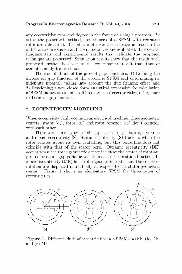
There are three types of air-gap eccentricity: static, dynamicand mixed eccentricity [8]. Static eccentricity (SE) occurs when therotor rotates about its own centerline, but this centerline does notcoincide with that of the stator bore. Dynamic eccentricity (DE)occurs when the rotor geometric center is not at the center of rotation,producing an air-gap periodic variation as a rotor position function. Inmixed eccentricity (ME) both rotor geometric center and the center ofrotation are displaced individually in respect to the stator geometriccenter. Figure 1 shows an elementary SPSM for three types ofeccentricities.
(a) (b) (c)
Figure 1. Different kinds of eccentricities in a SPSM. (a) SE, (b) DE,and (c) ME.

392 Akbari
The air gap length variation under ME for an induction machinecan be described by air gap function as follows [18]:
g(ϕ,ϕm, δ) = g0 (1− δ cos (ϕ− ϕm)) (1)
where
δ =[δ2s + δ2
d + 2δsδd cos (θ − ϕs)]1/2 (2)
ϕm = ϕs + tan−1
(δd sin(θ − ϕs)
δs + δd cos (θ − ϕs)
)(3)
where, g0 is air gap length for healthy machine, θ the rotor positionangle in stator reference frame, ϕ the angle in stator reference frame,ϕs the angle at which rotation and stator centers are separated, andδs and δd are static and dynamic eccentricity levels, respectively.
These relations are used in the following section for developinganalytical expressions of inductances of eccentric SPSM.
3. ANALYTICAL EQUATIONS OF INDUCTANCES FORGENERAL ECCENTRICITY
According to MWFA, mutual inductance between two windings a andb in electrical machines, can be calculated by the following equation [6]:
Lab = µ0lr
2π∫
0
na ·Mb · g−1dϕ (4)
where
Mb = nb −
2π∫
0
g−1 · nbdϕ
/
2π∫
0
g−1dϕ
(5)
µ0 is the free space permeability, l the axial stack length of the machine,g−1 the inverse air gap function, na the turns function of winding a,and Mb the modified winding function of winding b.
Available analytical methods for calculation of inductancesof eccentric SPSM are based on the winding function theory.Although available analytical methods provide good knowledge aboutperformance of eccentric SPSM, they are based on simplification andgeometrical approximation of unsymmetrical models of the machineunder different eccentricities. In [12], the values of inductances of aneccentric SPSM have been determined using Fourier series expansionsof the inverse air gap function and numerical integration. In the recentstudies [17, 20], analytical expressions have been presented assuming

Progress In Electromagnetics Research B, Vol. 49, 2013 393
Figure 2. Approximated air gap function for a four pole eccentricSPSM (SE = 30%).
step function (Figure 2) for air gap distribution. In the present paper,effective air gap function which considers flux fringing effect is usedto develop analytical expressions without any development in Fourierseries.
To derive analytical expressions for inductances, the varying airgap length, due to the pole saliency, eccentricity and slots should firstbe modeled.
The influence of the pole saliency, can be taken into accountby using the effective pole opening distance. The effective openingbetween the poles is slightly larger than the actual opening due toflux fringing. The air-gap function is computed by modeling the fluxpaths through the air-gap regions using straight lines and circular arcsegments. The details of air gap function modeling in a salient polesynchronous machine considering flux fringing effect have been givenin [19].
Knowing the actual opening and air gap length, the effectiveopening is calculated as [19]:
O′ =γ
βg (6)
where
β =(1− u)2
2(1 + u2)
u =o
2g+
√1 +
(o
2g
)2
γ =4π
o
2gtan−1 o
2g− ln
√1 +
(o
2g
)2
(7)

394 Akbari
where, o is the actual opening length. The effective air gap lengthwithin the effective pole opening, for a healthy SPSM can be expressedas
geff (φ) =g
1− β(1− cos 2π
o ′ ϕ) (8)
The eccentricity can be taken into account according to (1).Therefore, the effective air gap length of an eccentric SPSM, ininterpolar space, can be described by air gap function as follows
gq (ϕ,ϕm, δ) =g0 (1− δ cos (ϕ− ϕm))
1− β(1− cos 2π
o ′ ϕ) (9)
Elsewhere, in polar space, the air gap length is
gd(ϕ,ϕm, δ) = g0(1− δ cos(ϕ− ϕm)) (10)
The subscripts d and q refer to the polar and interpolar regions,respectively.
In the case of static eccentricity, δ = δs and ϕm = ϕs and indynamic eccentricity δ = δd and ϕm = ϕd. In mixed eccentricity, bothδ and ϕm are rotor position dependent as (2) and (3). Therefore wecan define air gap function for SPSM with a general eccentricity fault,including static, dynamic and mixed eccentricities.
Figure 3 shows the effective air gap length for a four pole SPSMunder 30% SE condition. This effective function is used in the presentstudy for developing analytical equations.
Finally, the stator slots effect is taken into account by Carters’factor referred to the slots [19].
Figure 3. Effective air gap length for a four pole eccentric SPSM(for example: SE = 30%) used in this study for developing analyticalequations.

Progress In Electromagnetics Research B, Vol. 49, 2013 395
3.1. Inductances of Stator Phases
To derive the analytical equations for inductances of stator phases, it isassumed that the functions yd and yq are indefinite integrals as follows
yd(ϕ,ϕm, δ) =∫
g−1d (ϕ,ϕm, δ)dϕ (11)
yq(ϕ,ϕm, δ) =∫
g−1q (ϕ,ϕm, δ)dϕ (12)
where, g−1d and g−1
q are inverse air gap functions in polar and interpolarregions, respectively. Expression (11) is elaborated to yield
yd(ϕ,ϕm, δ) =1
g0
√1− δ2
cos−1
(cos(ϕ− ϕm)− δ
1− δ cos(ϕ− ϕm)
)(13)
Function yq is obtained as follows
yq(ϕ, ϕm, δ) =∫
1− β(1− cos 2πo ′ ϕ)
g0(1− δ cos(ϕ− ϕm))dϕ
=1− β
g0
∫1
(1− δ cos(ϕ− ϕm))dϕ
+β
g0
∫cos(o ′′ϕ)
(1− δ cos(ϕ− ϕm))dϕ (14)
where, o ′′ = 2πo ′ . yq can be defined as follows
yq(ϕ,ϕm, δ) =1− β
g0yd +
β
g0yq1 (15)
where, yd is derived earlier in the paper, and yq1 can be obtainedby some mathematical manipulations. This function is given inAppendix A.
It is assumed that functions y1 and y2 are the definite integrals asfollows
y1(ϕm, θ, δ) =
2π∫
0
g−1(ϕ,ϕm, θ, δ)dϕ (16)
y2(ϕm, θ, δ) =
2π∫
0
g−1(ϕ,ϕm, θ, δ)nb(ϕ)dϕ (17)
Separating the associated terms of polar and interpolar spaces,

396 Akbari
(16) results in
y1(ϕm, θ, δ) =p∑
i=1
θ+iθd+(i−1)θq∫
θ+(i−1)θd+(i−1)θq
g−1d (ϕ,ϕm, δ)dϕ
+
θ+iθd+iθq∫
θ+iθd+(i−1)θq
g−1q (ϕ,ϕm, δ)dϕ
(18)
where, θq = o ′ (effective pole opening distance) and θd = 2πp − θq in
radian. Using the definitions given in (11) and (12), y1 is obtained asfollows:
y1(ϕm, θ, δ) =p∑
i=1
(yd(θ + iθd + (i− 1)θq, ϕm, δ)− yd(θ + (i− 1)θd
+(i− 1)θq, ϕm, δ) + yq(θ + iθd + iθq, ϕm, δ)−yq(θ + iθd + (i− 1)θq, ϕm, δ)) (19)
where yd and yq are calculated from (13) and (15), respectively. In asimilar way, y2 is calculated in the whole range of ϕ. Function y isdefined as follows:
y(ϕm, θ, δ) =y2(ϕm, θ, δ)y1(ϕm, θ, δ)
(20)
Considering (5), (16), (17) and (20), MWF of winding b, Mb isderived as
Mb(ϕ,ϕm, θ, δ) = nb(ϕ)− y(ϕm, θ, δ) (21)
To drive an expression for stator phases inductances, (21) isreplaced in (4), then the associated terms of polar and interpolarregions are separated. Finally, Lab is obtained as (22). The detailsof evaluation of Lab have been given in Appendix B.
Lab = µ0lr
p∑
k=1
[i=x2k∑
i=x2k−1
na(ϕti)(nb(ϕti)−y(ϕm, θ, δ))(yd(ϕi+1, ϕm, δ)
−yd(ϕi, ϕm, δ)) +i=x2k+1∑
i=x2k
na(ϕti) (nb(ϕti)
−y(ϕm, θ, δ)) (yq(ϕi+1, ϕm, δ)− yd(ϕi, ϕm, δ))
](22)

Progress In Electromagnetics Research B, Vol. 49, 2013 397
In (22) ϕx2k−1to ϕx2k
are the stator slots being in polar region(ϕx2k
− ϕx2k−1= θd) and ϕx2k
to ϕx2k+1are the stator slots being in
interpolar region (ϕx2k+1− ϕx2k
= θq).
3.2. Inductances of Rotor Windings
The procedure presented in the previous section for stator phasesinductances, can be extended to rotor ones. To begin, (4) and (5)are rewritten in the rotor reference frame.
Lab = µ0lr
2π∫
0
na(β)Mb(β, βm, δ)g−1(β, βm, δ)dβ (23)
where
Mb(β, βm, δ) = nb(β)−
2π∫0
g−1(β, βm, δ).nb(β)dβ
2π∫0
g−1(β, βm, δ)dβ
(24)
β is angle in rotor reference frame. It is assumed that the functionsyrd and yrq to be the indefinite integral of the functions g−1
d and g−1q in
the rotor reference frame, respectively. Using some integration rules,yrd and yrq will be obtained. yrd and yrq are the same as yd and yq,but ϕ and ϕm are replaced with β and βm respectively.
Equation (16) is rewritten in rotor reference frame, as followsyr1(βm, δ)
=
2π∫
0
g−1(β, βm, δ)dβ
=p∑
i=1
iθd+(i−1)θq∫
(i−1)θd+(i−1)θq
g−1d (β, βm, δ)dβ+
iθd+iθq∫
iθd+(i−1)θq
g−1q (β, βm, δ)dβ
=p∑
i=1
[yrd (iθd+(i− 1)θq, βm, δ)−yrd ((i−1)θd+(i− 1)θq, βm, δ)
= +yrq(iθd + iθq, βm, δ)− yrq(iθd + (i− 1)θq, βm, δ)] (25)where yrd and yrq are derived earlier in the paper. In the same way,yr2 can be derived.
yr2(βm,δ)=
2π∫
0
g−1(β, βm, δ)nb(β)dβ
398 Akbari
=p∑
i=1
iθd+(i−1)θq∫
(i−1)θd+(i−1)θq
g−1d (β, βm, δ)na(β)dβ
+
iθd+iθq∫
iθd+(i−1)θq
g−1q (β, βm, δ)na(β)dβ
=p∑
i=1
na(βdi)
iθd+(i−1)θq∫
(i−1)θd+(i−1)θq
g−1d (β, βm, δ)dβ
+na(βqi)
iθd+iθq∫
iθd+(i−1)θq
g−1q (β, βm, δ)dβ
=p∑
i=1
[na(βdi)(yrd (iθd + (i− 1)θq, βm, δ)
−yrd ((i− 1)θd + (i− 1)θq, βm, δ)+na(βqi)(yrq(iθd+iθq,βm,δ)−yrq(iθd+(i−1)θq,βm,δ))] (26)
where, βdi = 2π(i− 1)/p and βdi = 2π(i− 1)/p + π/4.Mb in rotor reference frame is defined as follows
Mb(β, βm, δ) = nb(β)− yr2(βm, δ)yr1(βm, δ)
= nb(β)− yr(βm, δ) (27)
where yr1 and yr2 are calculated from (25) and (26).Replacing (27) in (23) and separating the associated terms of polar
and interpolar regions, the expression for rotor winding inductance isderived as
Lab =µ0lr
p∑i=1
na(βdi)(nb(βdi)− yr(βm, δ))
iθd+(i−1)θq∫
(i−1)θd+(i−1)θq
g−1d (β, βm, δ)dβ
+na(βqi)(nb(βqi)− yr(βm, δ))
iθd+iθq∫
iθd+(i−1)θq
g−1q (β, βm, δ)dβ
Lab =µ0lr
p∑i=1
[na(βdi)(nb(βdi)− yr(βm, δ))(yrd(iθd + (i− 1)θq, βm, δ)
−yrd((i− 1)θd + (i− 1)θq, βm, δ)) + na(βqi)(nb(βqi)
−yr(βm, δ))(yrq(iθd + iθq, βm, δ)− yrq(iθd + (i− 1)θq, βm, δ)) ]
(28)
where yr and yrd and yrq are derived earlier in the paper.
Progress In Electromagnetics Research B, Vol. 49, 2013 399
3.3. Mutual Inductances between Stator and Rotor
For mutual inductances between rotor windings and stator phases, thestator reference frame is used. An analytical expression for mutualinductances is obtained as follows:
Lab = µ0lr
p∑
k=1
[na(βdi +θ)
i=x2k∑
i=x2k−1
[(nb(ϕti)−y(ϕm, θ, δ))(yd(ϕi+1, ϕm, δ)
−yd(ϕi, ϕm, δ))]+ na(βqi + θ)
i=x2k+1∑
i=x2k
[(nb(ϕti)
−y(ϕm, θ, δ))(yq(ϕi+1, ϕm, δ)− yq(ϕi, ϕm, δ))]
](29)
where a and b are accounted for the rotor windings and stator phases,respectively. Functions y, yd and yq are defined earlier in the paper.
Therefore, the inductances of SPSM under different kinds ofeccentricities can be calculated in a unified technique by meansof (22), (28) and (29). In the presented analytical expressions, unlikeprevious proposals, effective form of pole shoes considering flux fringingeffect is taken into account.
4. COMPUTATION OF INDUCTANCES
In this section, by means of developed analytical expressions,inductances of a SPSM for healthy and different eccentricity conditionsare calculated in a unified technique, where the eccentricity type anddegree are selectable. A typical SPSM, with specifications given inAppendix C, is considered in this paper. It should be noted that,magnetic saturation and leakage flux are not included.
4.1. Magnetizing and Mutual Inductances of Stator Phases
Magnetizing inductance of stator phase a and mutual inductancebetween phases a and b of the stator have been computed underdifferent eccentricity conditions and are shown in Figures 4 and 5.
Comparison of plots in Figures 4 and 5 for the three types ofeccentricity shows that while ME causes asymmetrical self and mutualinductances, SE and DE cause symmetrical inductances. By increasingthe eccentricity severity, the magnitude of these inductances increases.

400 Akbari
(a) (b)
Figure 4. Calculated inductances of stator phases versusrotor position under healthy and different eccentricity conditions,(a) magnetizing inductance of stator phase a, and (b) mutualinductance between phases a and b of the stator.
(a) (b)
Figure 5. Calculated inductances of stator phases versus rotorposition under healthy and ME conditions (SE = 30%, DE =60%), (a) magnetizing inductance of stator phase a, and (b) mutualinductance between phases a and b of the stator.
4.2. Magnetizing Inductance of Rotor Winding
The plots of magnetizing inductance of rotor winding for differenteccentricities are shown in Figure 6. Comparison of plots in Figure 6shows how SE, DE and ME affect the profile of the magnetizinginductance of rotor winding. ME causes a pulsating magnetizinginductance of rotor winding, whereas, DE and SE cause a symmetricalinductance with a larger magnitude compared to the non-eccentric

Progress In Electromagnetics Research B, Vol. 49, 2013 401
Figure 6. Calculated magnetizing inductance of rotor winding versusrotor position, under healthy and different eccentricity conditions.
Figure 7. Calculated mutual inductance between stator phase a androtor winding under different eccentricity conditions.
condition. By increasing the eccentricity level, the magnitude of thisinductance increases.
4.3. Mutual Inductances between Stator Phases and RotorWinding
Figure 7 shows the mutual inductance between stator phase a and rotorwinding for different eccentricity cases.
Comparison of the inductance profiles in Figure 7 indicates thatSE and DE increase the magnitude of mutual inductance whereasthere is no asymmetry in the inductance distribution and ME createsasymmetrical inductance distribution.

402 Akbari
5. EXPERIMENTAL RESULTS
To validate the theoretical and simulated results, experiments wereperformed on a machine identical to the one simulated. A techniquewas used to make the machine temporarily eccentric with differenttypes and degrees of eccentricities. The stator and the rotor bearingsat the two ends of the motor were separately mounted on the testbed. Therefore, it was possible to displace any of bearings separatelyand create different static eccentricities. To be able to create dynamiceccentricity, bearings were replaced by other bearings with differentdiameter. Special screws were used to fix the bearings. The positionof bearings was accurately checked by a clock. The clock and specialscrew are shown in Figure 8.
Clock
Special screw
Figure 8. Test bed.
To obtain the mutual inductance between stator phase a andstator phase b, a sinusoidal voltage was applied in stator phase a andthe voltage induced in the stator phase b was measured as a functionof the rotor position from 0 to 360 taking 3 steps. The mutualinductance was calculated as follows:
Lab(θ) =Vb(θ)Va(θ)
Laa(θ) (30)
where Va(θ) and Vb(θ) are induced voltages in stator phase a andstator phase b, respectively and Laa(θ) is self inductance of statorphase a, previously calculated by means of phase a voltage and currentmeasurements.
The induced voltage in phase A was derived as follows:
VA =√
V 2s − (rAiA)2 (31)
where Vs is the applied voltage, iA is the current following in statorphase A and rA is stator phase A resistance (1.36Ω). To avoid the

Progress In Electromagnetics Research B, Vol. 49, 2013 403
Figure 9. Mutual inductance between stator phase a and rotorwinding under healthy and different eccentricities for the experimentand simulation.
Figure 10. Mutual inductance between stator phase a and statorphase b under healthy and different eccentricities for the experimentand simulation.
magnetic saturation, a low ac voltage was applied. The phase A voltagedrop was negligible in the experiments.
The mentioned process was repeated to obtain the mutualinductance between stator phase a and rotor winding.
Figures 9 and 10 show the profiles of mutual inductances undereccentricity conditions for the experiment and simulation. It isapparent that the inductance profiles coming from the simulation andexperiment demonstrate a satisfactory mach. The reasons of thisagreement are as follows: 1) a more realistic distribution of the air

404 Akbari
Figure 11. Calculated mutual inductance between stator phase aand phase b, for machine under 50% static eccentricity from proposedanalytical method, available analytical method and experiment.
gap in the presence of eccentricity considering flux fringing effect isused, 2) development in Fourier series of the inverse air gap functionhas not been used, but closed form analytical equations are employedfor inductances calculation and 3) real spatial distribution of statorphases and rotor winding has also been taken into account.
Figure 11 shows the mutual inductance between stator phase a andphase b for machine under 50% static eccentricity from simulations andexperiment. The inductance was calculated using proposed analyticalmethod and available analytical method in which, the air gap functionis estimated by a step function. The comparison between inductanceprofiles indicates that the maximum value of the inductance from theproposed method is slightly lower than the available method result.The main reason is that in the proposed method the flux fringing effectis considered, while in previous analytical method, based on windingfunction theory, this effect is excluded.
As shown, the result with proposed method is closer to theexperimental result than that of available method. Probably,the difference between results from the proposed method and theexperiment is due to neglecting the slots flux leakages. This claimneeds more detailed study.
6. CONCLUSIONS
In this study, a new analytical model for SPSM under generaleccentricity fault has been developed, capable of accounting for themachine geometry, effect of flux fringing, slots effect and spatialdistribution of machine windings. While in previous analytical

Progress In Electromagnetics Research B, Vol. 49, 2013 405
methods, air gap function has been estimated and therefore geometricalmodel has been simplified, in this paper, effective air gap functionwhich considers flux fringing effect is taken into account.
By using the effective air gap function of the eccentric SPSMand determining its indefinite integral, precise analytical equationsfor inductances have been obtained. Derived comprehensiveequations allow calculating time varying inductances of SPSMunder any eccentricity type and degree, with a general simulationtechnique. Analytical equations prevent imprecision due to numericaldifferentiations. Moreover, the computational time is decreased thanksto an exact and analytical definition of the distribution functions, incontrast to methods based on only an approximation with Fourierseries.
Simulation results show that the result with the proposed methodis closer to the experimental result than that of available analyticalmethods. The main reason is that in the proposed method the fluxfringing effect is considered, while in previous analytical method, basedon winding function theory, this effect is excluded and the air gapdistribution is estimated by step function. Since the calculation ofinductances is an essential step for simulation and analysis of faultin electrical machines, the proposed method will improve the on-line diagnosis of the fault. The author plans to apply the evaluatedinductances in a coupled electromagnetic model of SPSM in the futurefor fault analysis.
ACKNOWLEDGMENT
This work was supported by the Office of Vice Chancellor for Research,Yazd Branch, Islamic Azad University, Yazd, Iran. The author wouldlike to thank Dr. H. Meshgin Kelk for providing information regardingthe installed 9 KVA synchronous machine in the electrical machinesresearch Lab, Tafresh University, Iran and Prof. J. Milimonfared fromAmirkabir University of technology, Tehran, Iran.

406 Akbari
APPENDIX A.
yq1
=−
[(o ′′/2)δ4−(o ′′δ)2+o ′′2
]cos (o ′′φm)
δ4√
δ2 − 1tanh−1
(δ+1√δ−1
tan(
φ−φm
2
))
+o ′′δ2−2o ′′
δ4
[(φ−φm)cos(o ′′φm)+sin(o ′′φm) ln (1−δ cos (φ−φm))
]
− 2δ2
sin(2φ + 2φm)− 23δ
sin(3φ + φm) +2δ2 − 2o ′′
δ3sin(φ + 3φm)
fq(ϕ,ϕm, δ)
=1− β
g0
∫1
(1− δ cos(ϕ− ϕm))dϕ +
β
g0
∫cos 2π
o ′ ϕ
(1− δ cos(ϕ− ϕm))dϕ.
APPENDIX B.
Replacing (21) in (4) and separating the associated terms of polar andinterpolar regions, Lab is obtained as follows:
Lab = µ0lr
p∑
i=1
[ θ+iθd+(i−1)θq∫
θ+(i−1)θd+(i−1)θq
g−1d (ϕ, ϕm, θ, δ)na(ϕ)(nb(ϕ)
−y(ϕm, θ, δ))dϕ +
θ+iθd+iθq∫
θ+iθd+(i−1)θq
g−1q (ϕ, ϕm, θ, δ)na(ϕ)(nb(ϕ)
−f(ϕm, θ, δ))dϕ
](B1)
where a and b are accounted for the stator phases. It is assumed thatϕx2k−1
to ϕx2kare the stator slots being in polar region (ϕx2k
−ϕx2k−1=
θd) and ϕx2kto ϕx2k+1
are the stator slots being in interpolar region(ϕx2k+1
− ϕx2k= θq). Therefore
Lab=µ0lr
p∑
k=1
i=x2k∑
i=x2k−1
na(ϕti)(nb(ϕti)−f(ϕm, θ, δ))
ϕi+1∫
ϕi
g−1d (ϕ,ϕm, δ)dϕ
+i=x2k+1∑
i=x2k
na(ϕti)(nb(ϕti)−f(ϕm, θ, δ))
ϕi+1∫
ϕi
g−1q (ϕ,ϕm, δ)dϕ
(B2)
Progress In Electromagnetics Research B, Vol. 49, 2013 407
where ϕi is angle of stator slot i center, ϕti is angular position betweenstator slot i and stator slot i+1 (angle of stator tooth i). ϕx2k−1
, ϕx2k
and ϕx2k+1can be easily determined at every time step of simulation.
Using the definitions given in (11) and (12), Lab is obtained as (22).
APPENDIX C.
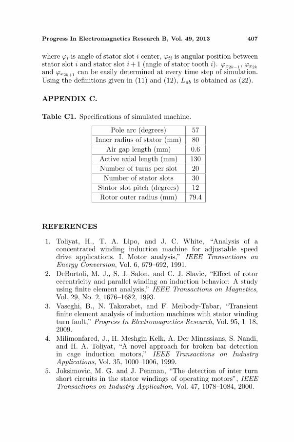
Table C1. Specifications of simulated machine.
Pole arc (degrees) 57Inner radius of stator (mm) 80
Air gap length (mm) 0.6Active axial length (mm) 130Number of turns per slot 20Number of stator slots 30
Stator slot pitch (degrees) 12Rotor outer radius (mm) 79.4
REFERENCES
1. Toliyat, H., T. A. Lipo, and J. C. White, “Analysis of aconcentrated winding induction machine for adjustable speeddrive applications. I. Motor analysis,” IEEE Transactions onEnergy Conversion, Vol. 6, 679–692, 1991.
2. DeBortoli, M. J., S. J. Salon, and C. J. Slavic, “Effect of rotoreccentricity and parallel winding on induction behavior: A studyusing finite element analysis,” IEEE Transactions on Magnetics,Vol. 29, No. 2, 1676–1682, 1993.
3. Vaseghi, B., N. Takorabet, and F. Meibody-Tabar, “Transientfinite element analysis of induction machines with stator windingturn fault,” Progress In Electromagnetics Research, Vol. 95, 1–18,2009.
4. Milimonfared, J., H. Meshgin Kelk, A. Der Minassians, S. Nandi,and H. A. Toliyat, “A novel approach for broken bar detectionin cage induction motors,” IEEE Transactions on IndustryApplications, Vol. 35, 1000–1006, 1999.
5. Joksimovic, M. G. and J. Penman, “The detection of inter turnshort circuits in the stator windings of operating motors”, IEEETransactions on Industry Application, Vol. 47, 1078–1084, 2000.
408 Akbari
6. Al-Nuaim, N. A. and H. Toliyat, “A novel method for modelingdynamic air-gap eccentricity in synchronous machines based onmodified winding function theory,” IEEE Transactions on EnergyConversion, Vol. 13, 156–162, 1998.
7. Tabatabaei, I, J. Faiz, H. Lesani, and M. T. Nabavi-Razavi,“Modeling and simulation of a salient pole synchronous generatorwith dynamic eccentricity using modified winding functionapproach,” IEEE Transactions on Magnetics, Vol. 40, No. 3,May 2004.
8. Joksimovic, G. M., “Dynamic simulation of cage inductionmachine with air gap eccentricity,” IEE Proc. Electr. Power Appl.,Vol. 152, No. 4, 803–811, July 2005.
9. Mishra, C., A. Routray, and S. Mukhopadhyay, “A computation-ally efficient winding function method for calculation of induc-tances in an asymmetric induction motor,” Electric Power Com-ponents and Systems, Vol. 35, No. 1, 43–61, 2007.
10. Akbari, H., H. Meshgin Kelk, and J. Milimonfared, “Extension ofwinding function theory for radial and axial non-uniform air gap insalient pole synchronous machines,” Progress In ElectromagneticsResearch, Vol. 114, 407–428, 2011.
11. Lubin, T. and T. Hamiti, H. Razik, and A. Rezzoug, “Comparisonbetween finite element analysis and winding function theory forinductances and torque calculation of a synchronous reluctancemachine,” IEEE Transactions on Magnetics, Vol. 43, No. 8, 3406–3410, 2007.
12. Babaei, M., J. Faiz, B. M. Ebrahimi, S. Amini, and J. Nazarzadeh,“A detailed analytical model of a salient-pole synchronousgenerator under dynamic eccentricity fault,” IEEE Transactionson Magnetics, Vol. 47, No. 4, 64–771, 2011.
13. Toliyat, H. A. and N. A. Al-Nuaim, “Simulation and detectionof dynamic air-gap eccentricity in salient-pole synchronousmachines,” IEEE Transactions on Industry Applications, Vol. 35,No. 1, 86–93, 1999.
14. Tu, X., L.-A. Dessaint, M. El Kahel, and A. Barry, “Modelingand experimental validation of internal faults in salient polesynchronous machines including space harmonics,” Mathematicsand Computers in Simulation, Vol. 71, 425–439, 2006.
15. Neti, P. and S. Nandi, “Stator interturn fault detection ofsynchronous machines using field current and rotor search-coil voltage signature analysis,” IEEE Transactions on IndustryApplications, Vol. 45, No. 3, 911–920, 2009.
16. Dehkordi, A., P. Neti, A. Gole, and T. Maguire, “Development

Progress In Electromagnetics Research B, Vol. 49, 2013 409
and validation of a comprehensive synchronous machine modelfor a real time environment,” IEEE Transactions on EnergyConversion, Vol. 25, No. 1, 34–48, 2010.
17. Akbari, H., J. Milimonfared, and H. Meshgin Kelk, “A noveltechnique for the computation of inductances of salient polemachines under different eccentricity conditions,” Electric PowerComponents and Systems, Vol. 39, No. 14, 1507–1522, 2011.
18. Faiz, J., I. Tabatabaei, and E. Sharifi, “A precise electromagneticmodeling and performance analysis of a three-phase squirrel-cage induction motor under mixed eccentricity condition,”Electromagnetics, Vol. 24, 471–489, 2004.
19. Ostovic, V., Computer Aided Analysis of Electrical Machines,A Mathematical Approach, Prentice Hall, Englewood Cliffs, NJ,1994.
20. Akbari, H., “Analytical computation of reluctance synchronousmachine inductances under different eccentricity faults,” ProgressIn Electromagnetics Research M, Vol. 24, 29–44, 2012.
Related Documents