Available online at www.sciencedirect.com Sensors and Actuators A 142 (2008) 369–378 An implantable ZigBee ready telemetric platform for in vivo monitoring of physiological parameters Pietro Valdastri a,∗ , Stefano Rossi a , Arianna Menciassi a , Vincenzo Lionetti b , Fabio Bernini b , Fabio A. Recchia b , Paolo Dario a a CRIM Lab, Polo Sant’Anna Valdera, Scuola Superiore Sant’Anna, Pisa, Italy b Sector of Medicine, Scuola Superiore Sant’Anna, Pisa, Italy Received 30 September 2006; received in revised form 27 March 2007; accepted 10 April 2007 Available online 19 April 2007 Abstract This paper presents a multiple channel, bidirectional and implantable biotelemetric platform, suitable for real time in vivo monitoring of several physiological parameters. This system consists of an implantable unit, an external host and a user terminal. The ZigBee wireless technology, functioning as telemetric link, enables long battery lifetime and offers the opportunity to build up complex wireless networks of implantable and wearable sensors. A smart Analog Front End, that allows a real time optimization of the signals output dynamics, is also described. Different kinds of sensors, ranging from resistive to current or voltage output sensors, can be directly connected to the front end. The firmware code of the implanted unit can be reprogrammed through the telemetric link, thus enabling active interactions between the system and the end user. For the code development, particular attention was devoted to reducing power consumption: a theoretical maximum battery life of several years, suitable for chronic implants, can be achieved. In order to validate the platform, a ZigBee point to point wireless connection between the implant and the external unit was implemented. Two different sensors were used, i.e. a temperature sensor and a pressure transducer. The system performances were assessed through several in vivo tests. In particular, aortic and ventricular real time pressure and temperature monitoring are reported with the system implanted in farm pigs. Data acquisition was validated by comparison with medical golden standard for pressure monitoring. Finally, the lowest level of transmission power required to establish a reliable communication by using a ZigBee compliant hardware implanted under skin has been quantified as 13.33 W during an in vivo experiment in an anesthetized pig. This value is fully compliant with the reference level for general public exposure to time varying electric and magnetic fields. © 2007 Elsevier B.V. All rights reserved. Keywords: ZigBee; Biotelemetry; Implantable devices; Chronic implants 1. Introduction The range of implantable biomedical devices will increase substantially over the next 8 years, thanks to the improvements in MicroSytems Technology (MST) achieved during the last decade [1]. Percutaneous connections with leads and cables present obvious disadvantages: they limit the patient’s mobility and, moreover, they can cause skin irritations or infections, thus contributing to deteriorate health conditions. Although a wireless link is not an essential requirement for physiological parameters monitoring from implanted sensors, the aforemen- tioned issue is one of the main motivations for the trend in ∗ Corresponding author. Tel.: +39 050883489; fax: +39 050883497. E-mail address: [email protected] (P. Valdastri). modern biomedical implanted systems to use wireless technol- ogy [2]. Examples of physiological data acquisition platforms with wireless links include a wide range of different biomedical applications. In [3], Coosemans and Puers obtained a continu- ous wireless intracavitary pressure monitoring in bladder, while other authors have assembled neural prosthetic devices [4–6]. An implantable telemetry platform for in vivo monitoring of several physiological parameters is proposed in [7]. This device, based on a digital microcontroller (C), can sample and transmit up to three analog signals coming from different sensors and can be programmed in order to perform different measurement protocols. A biotelemetric system for ambulatory esophageal pH monitoring is already commercially available and its performances are well-characterized [8]. This device is attached to the mucosal wall of the esophagus and is specifically designed to diagnose gastro-esophageal reflux disease (GERD). 0924-4247/$ – see front matter © 2007 Elsevier B.V. All rights reserved. doi:10.1016/j.sna.2007.04.035

Welcome message from author
This document is posted to help you gain knowledge. Please leave a comment to let me know what you think about it! Share it to your friends and learn new things together.
Transcript
A
pfwkicfewslbp©
K
1
sidpatwpt
0d
Available online at www.sciencedirect.com
Sensors and Actuators A 142 (2008) 369–378
An implantable ZigBee ready telemetric platform for in vivomonitoring of physiological parameters
Pietro Valdastri a,∗, Stefano Rossi a, Arianna Menciassi a, Vincenzo Lionetti b,Fabio Bernini b, Fabio A. Recchia b, Paolo Dario a
a CRIM Lab, Polo Sant’Anna Valdera, Scuola Superiore Sant’Anna, Pisa, Italyb Sector of Medicine, Scuola Superiore Sant’Anna, Pisa, Italy
Received 30 September 2006; received in revised form 27 March 2007; accepted 10 April 2007Available online 19 April 2007
bstract
This paper presents a multiple channel, bidirectional and implantable biotelemetric platform, suitable for real time in vivo monitoring of severalhysiological parameters. This system consists of an implantable unit, an external host and a user terminal. The ZigBee wireless technology,unctioning as telemetric link, enables long battery lifetime and offers the opportunity to build up complex wireless networks of implantable andearable sensors. A smart Analog Front End, that allows a real time optimization of the signals output dynamics, is also described. Differentinds of sensors, ranging from resistive to current or voltage output sensors, can be directly connected to the front end. The firmware code of themplanted unit can be reprogrammed through the telemetric link, thus enabling active interactions between the system and the end user. For theode development, particular attention was devoted to reducing power consumption: a theoretical maximum battery life of several years, suitableor chronic implants, can be achieved. In order to validate the platform, a ZigBee point to point wireless connection between the implant and thexternal unit was implemented. Two different sensors were used, i.e. a temperature sensor and a pressure transducer. The system performancesere assessed through several in vivo tests. In particular, aortic and ventricular real time pressure and temperature monitoring are reported with the
ystem implanted in farm pigs. Data acquisition was validated by comparison with medical golden standard for pressure monitoring. Finally, theowest level of transmission power required to establish a reliable communication by using a ZigBee compliant hardware implanted under skin haseen quantified as 13.33 �W during an in vivo experiment in an anesthetized pig. This value is fully compliant with the reference level for generalublic exposure to time varying electric and magnetic fields.
2007 Elsevier B.V. All rights reserved.
mowaooAod
eywords: ZigBee; Biotelemetry; Implantable devices; Chronic implants
. Introduction
The range of implantable biomedical devices will increaseubstantially over the next 8 years, thanks to the improvementsn MicroSytems Technology (MST) achieved during the lastecade [1]. Percutaneous connections with leads and cablesresent obvious disadvantages: they limit the patient’s mobilitynd, moreover, they can cause skin irritations or infections,hus contributing to deteriorate health conditions. Although a
ireless link is not an essential requirement for physiologicalarameters monitoring from implanted sensors, the aforemen-ioned issue is one of the main motivations for the trend in∗ Corresponding author. Tel.: +39 050883489; fax: +39 050883497.E-mail address: [email protected] (P. Valdastri).
asmeaad
924-4247/$ – see front matter © 2007 Elsevier B.V. All rights reserved.oi:10.1016/j.sna.2007.04.035
odern biomedical implanted systems to use wireless technol-gy [2]. Examples of physiological data acquisition platformsith wireless links include a wide range of different biomedical
pplications. In [3], Coosemans and Puers obtained a continu-us wireless intracavitary pressure monitoring in bladder, whilether authors have assembled neural prosthetic devices [4–6].n implantable telemetry platform for in vivo monitoringf several physiological parameters is proposed in [7]. Thisevice, based on a digital microcontroller (�C), can samplend transmit up to three analog signals coming from differentensors and can be programmed in order to perform differenteasurement protocols. A biotelemetric system for ambulatory
sophageal pH monitoring is already commercially availablend its performances are well-characterized [8]. This device isttached to the mucosal wall of the esophagus and is specificallyesigned to diagnose gastro-esophageal reflux disease (GERD).
3 d Actu
Ois
oTtriwhatobttSegtata(fIfipwbaShcaia
nPitrsb
tepdfW
spe
trsBsoictasb
cl[hia
lraAtcdptbi
�sdbttdrettZLmtrda
2
70 P. Valdastri et al. / Sensors an
ther systems aimed at monitoring pH consist of sensors placednside a swallowable capsule that can transmit the acquiredignal while traveling through the gastro-intestinal tract [9,10].
All of the above mentioned devices are custom made and eachf them utilizes a different transmission frequency and protocol.his allows optimization of power consumption and minimiza-
ion of dimensions, but, at the same time, limits flexibility andeconfigurability. In particular, none of these systems can be eas-ly linked together in a wireless network of implanted sensorsorking in synergy with an external base station installed in theospital or at the subject’s home. Tang et al. [11] prospectedvision of the near future when single devices will be able
o form a wireless sensor network comprising a large numberf nodes, whose placement inside and outside the body cane either pre-determined or random, according to the applica-ion. This vision can only be achieved by using a widespreadelecommunication standard for the wireless telemetric link.tandard hardware and software architectures facilitate interop-rable devices that are expected to significantly influence nexteneration health systems. A number of these devices can behen integrated into a Wireless Body Area Network (WBAN),new enabling technology for health monitoring [12]. In par-
icular, the three leading contending standards for short rangend low power wireless communications are Ultra Wide BandUWB), Bluetooth and ZigBee [13]. These three solutions deriverom the IEEE 802.15 Standard family and use the 2.4 GHzndustrial, Scientific and Medical (ISM) frequency band. Therst one, also known as Wi-Fi or wireless LAN, has been pur-osely developed for very high data rates (tens of Mbps) inireless communications, like the Radio Frequency (RF) linketween two personal computers, and it is highly demandings regards the power consumption and the overall dimensions.ince biomedical monitoring usually does not require such aigh data throughput, this standard has been used for biomedi-al monitoring in the recent past [14], but it has been discardeds soon as more compact and power efficient solutions, evenf with a lower data transmission rate, became commerciallyvailable.
Bluetooth has been primarily designed as a wireless tech-ology for cable replacement operation, for example, amongersonal Digital Assistants (PDA), mobile phones and headsets
n a Personal Area Network (PAN). For such fields of applica-ion, high data rates (1 Mbps) and continuous data transfer ineal time are required. This translates into quite high power con-umption that limits the battery life of an implanted system foriomedical monitoring, typically to some weeks [15].
ZigBee is the name of the alliance between several elec-ronics companies (i.e. Philips, Motorola, Atmel, Mitsubishi)stablished in order to develop and promote the IEEE 802.15.4rotocol [16]. The goal of this protocol is to provide a stan-ard with ultra low power consumption, cost, and complexityor fixed or portable devices operating in a Low Rate (250 kbps)
ireless Personal Area Network (LR-WPAN).
As clearly stated by Hofmann et al. [17], ZigBee is perfectlyuitable in terms of data rate for the wireless transmission ofhysiological vital signs. Even the continuous monitoring of anlectrocardiogram (ECG) waveform, which is known as one of
dsU
ators A 142 (2008) 369–378
he most demanding biomedical signals in terms of samplingate, was reliably accomplished using ZigBee. The power con-umption due to data transmission is nearly equivalent to theluetooth standard, but ZigBee benefits from its ultra low power
leep mode and very short wake up times, thus achieving typicalperative lifecycles of several years with no need for batter-es replacement. Furthermore, the ZigBee standard enables thereation of very complex networks, thanks to address specifica-ions that allow to connect up to 65,536 devices. This represents
very promising opportunity for the development of multi-ubject monitoring applications or implantable networks withoth diagnostic and related drug delivery capabilities.
Lubrin et al. have recently reported a wireless remote health-are monitoring that takes advantage of he ZigBee wirelessink [18]. This system is based on the Berkeley Motes platform19] and each node could be used to monitor body temperature,eart rate, as well as many other parameters. However this works focused on a set of wearable sensors and does not directlyddress implantable solutions.
In order to implement a standard approach to the telemetricink, a digital is almost mandatory as the core component of theemote unit. Thanks to the presence of a certain amount of digitalnd programmable “intelligence”, it is possible to design a smartnalog Front End (AFE), capable, for example, of multiplexing
he different sensor inputs, remove an eventual offset level andhanging the channel amplification in order to fit the outputynamic range [15,20–22]. Furthermore, the signal conditioningarameters can be selected in real time by the user, through theelemetric link, and the sensing part of the remote board cane temporarily switched off to save power during periods ofnactivity.
In the present study the authors developed an implantable,C-based platform for biotelemetry with a “smart” AFE. A
ystem overview of both the implanted unit and the externalata collector is given in Section 2. The ZigBee standard haseen chosen as the ideal candidate for the telemetric link withhe implantable unit. One of the main goals of this study waso evaluate the performance of ZigBee compatible device forata transmission during an in vivo experiment. The power levelequired for a reliable transmission has been experimentallyvaluated and the results are discussed in Section 3, with a par-icular focus on safety issues. To achieve this objective, a pointo point wireless connection has been implemented, even if theigBee standard allows very complex network configurations.ower layers and low level features of ZigBee stack were imple-ented in the chosen hardware and in the firmware, according
o this goal. The in vivo assessment of the functionality andeliability of the telemetric link would then enable the futureevelopment of star and mesh wireless topologies of implantednd external monitoring units.
. System overview
The whole platform is composed of the implantable unit,escribed in Section 2.1, the receiving unit, connected to a Per-onal Computer (PC) by the serial cable, and a simple Graphicalser Interface (GUI), both described in Section 2.2.
P. Valdastri et al. / Sensors and Actuators A 142 (2008) 369–378 371
of t
2
tbp
2
tdi(tCcmi
bUbfvIpdpti
dtbpmh
iUcar
P
sfspUa6atsts
sr
G
Rp
R
wFf
G
tt1Wbt
c
ho
f
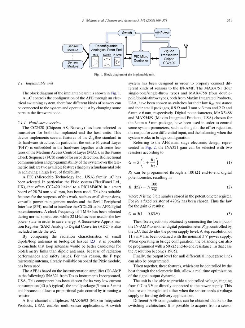
Fig. 1. Block diagram
.1. Implantable unit
The block diagram of the implantable unit is shown in Fig. 1.A �C controls the configuration of the AFE through an elec-
rical switching system, therefore different kinds of sensors cane connected to the system and operated just by changing somearts in the firmware code.
.1.1. Hardware overviewThe CC2420 (Chipcon AS, Norway) has been selected as
ransceiver for both the implanted and the host units. Thisevice implements several features of the ZigBee standard ints hardware structure. In particular, the entire Physical LayerPHY) is embedded in the hardware together with some fea-ures of the Medium Access Control Layer (MAC), as the Frameheck Sequence (FCS) control for error detection. Bidirectionalommunication and programmability of the system over the tele-etric link are two available features that play a fundamental role
n achieving a high level of flexibility.A PIC (Microchip Technology Inc., USA) family �C has
een selected. In particular, the Pixie system (FlexiPanel Ltd.,K), that offers CC2420 linked to a PIC18F4620 in a smartoard of 28.74 mm × 41 mm, has been used. This has suitableeatures for the purposes of this work, such as small dimensions,ersatile power management modes and the Serial Peripheralnterface (SPI), useful to interface the CC2420 to the AFE digitalotentiometers. A clock frequency of 1 MHz has been selecteduring normal operations, while 32 kHz has been used in the lowower state in order to save energy. A Successive Approxima-ion Register (SAR) Analog to Digital Converter (ADC) is alsoncluded inside the �C.
By comparing the radiation characteristics of smallipole/loop antennas in biological tissues [23], it is possibleo conclude that loop antennas would be better candidates foriotelemetry links than dipole antennas, because of radiationerformances and safety issues. For this reason, the F typeicrostrip antenna, already available on board the Pixie module,
as been used.The AFE is based on the instrumentation amplifier (IN-AMP
n the following) INA321 from Texas Instruments Incorporated,SA. This component has been chosen for its very low current
onsumption (40 �A typical), the small package (5 mm × 3 mm)
nd because it allows a proportional gain control by trimming aesistor.A four-channel multiplexer, MAX4692 (Maxim Integratedroducts, USA), enables multi-sensor applications. A switch
fs
s
he implantable unit.
ystem has been designed in order to properly connect dif-erent kinds of sensors to the IN-AMP. The MAX4751 (fouringle-pole/single-throw type) and MAX4758 (four double-ole/double-throw type), both from Maxim Integrated Products,SA, have been chosen as switches for their low Ron resistance
nd their small packages, 0.9 � and 3 mm × 3 mm and 2 � andmm × 6 mm, respectively. Digital potentiometers, MAX5488nd MAX5489 (Maxim Integrated Products, USA) chosen forhe 3 mm × 3 mm package, have been used in order to controlome system parameters, such as the gain, the offset rejection,he output for zero differential input, and the balancing when theystem works in bridge configuration.
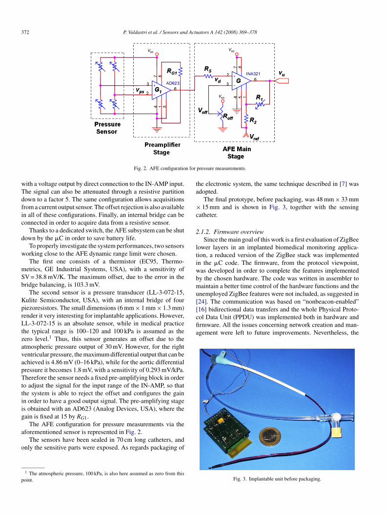
Referring to the AFE main stage electronic design, repre-ented in Fig. 2, the INA321 gain can be selected with twoesistors according to
= 5
(1 + R1
R2
)(1)
1 can be programmed through a 100 k� end-to-end digitalotentiometer, resulting in
1 (k�) = N100
256(2)
here N is the 8 bit number stored in the potentiometer register.or R2 a fixed resistor of 470 � has been chosen. Thus the lawor the gain G results:
= 5(1 + 0.83N) (3)
The offset rejection is obtained by connecting the low input ofhe IN-AMP to another digital potentiometer, Roff, controlled byhe �C, that divides the power supply level. A step resolution of1.8 mV has been obtained with the nominal 3 V power supply.hen operating in bridge configuration, the balancing can also
e programmed with a 50 k� end-to-end resistance. In that casehe resolution becomes 196 �.
Finally, the output level for null differential input (zero line)an also be programmed.
Taken together, these features, which can be controlled by theost through the telemetric link, allow a real time optimizationf the signal output dynamic.
The unit is also able to provide a controlled voltage, rangingrom 0.7 to 3 V or directly connected to the power supply. This
eature can be exploited either when the sensor needs a voltageupply or for drug delivery applications.Different AFE configurations can be obtained thanks to thewitching architecture. It is possible to acquire from a sensor
372 P. Valdastri et al. / Sensors and Actuators A 142 (2008) 369–378
n for
wTdfic
d
w
mSb
KprLtzavapTttiig
a
o
p
ta
×c
2
ltiwbmu[[16] bidirectional data transfers and the whole Physical Proto-col Data Unit (PPDU) was implemented both in hardware andfirmware. All the issues concerning network creation and man-agement were left to future improvements. Nevertheless, the
Fig. 2. AFE configuratio
ith a voltage output by direct connection to the IN-AMP input.he signal can also be attenuated through a resistive partitionown to a factor 5. The same configuration allows acquisitionsrom a current output sensor. The offset rejection is also availablen all of these configurations. Finally, an internal bridge can beonnected in order to acquire data from a resistive sensor.
Thanks to a dedicated switch, the AFE subsystem can be shutown by the �C in order to save battery life.
To properly investigate the system performances, two sensorsorking close to the AFE dynamic range limit were chosen.The first one consists of a thermistor (EC95, Thermo-
etrics, GE Industrial Systems, USA), with a sensitivity ofV = 38.8 mV/K. The maximum offset, due to the error in theridge balancing, is 103.3 mV.
The second sensor is a pressure transducer (LL-3-072-15,ulite Semiconductor, USA), with an internal bridge of fouriezoresistors. The small dimensions (6 mm × 1 mm × 1.3 mm)ender it very interesting for implantable applications. However,L-3-072-15 is an absolute sensor, while in medical practice
he typical range is 100–120 and 100 kPa is assumed as theero level.1 Thus, this sensor generates an offset due to thetmospheric pressure output of 30 mV. However, for the rightentricular pressure, the maximum differential output that can bechieved is 4.86 mV (0–16 kPa), while for the aortic differentialressure it becomes 1.8 mV, with a sensitivity of 0.293 mV/kPa.herefore the sensor needs a fixed pre-amplifying block in order
o adjust the signal for the input range of the IN-AMP, so thathe system is able to reject the offset and configures the gainn order to have a good output signal. The pre-amplifying stages obtained with an AD623 (Analog Devices, USA), where theain is fixed at 15 by RG1.
The AFE configuration for pressure measurements via the
forementioned sensor is represented in Fig. 2.The sensors have been sealed in 70 cm long catheters, andnly the sensitive parts were exposed. As regards packaging of
1 The atmospheric pressure, 100 kPa, is also here assumed as zero from thisoint.
pressure measurements.
he electronic system, the same technique described in [7] wasdopted.
The final prototype, before packaging, was 48 mm × 33 mm15 mm and is shown in Fig. 3, together with the sensing
atheter.
.1.2. Firmware overviewSince the main goal of this work is a first evaluation of ZigBee
ower layers in an implanted biomedical monitoring applica-ion, a reduced version of the ZigBee stack was implementedn the �C code. The firmware, from the protocol viewpoint,as developed in order to complete the features implementedy the chosen hardware. The code was written in assembler toaintain a better time control of the hardware functions and the
nemployed ZigBee features were not included, as suggested in24]. The communication was based on “nonbeacon-enabled”
Fig. 3. Implantable unit before packaging.
d Actu
da
maortadt
utmris
••••
r
iaiptetc
rapcSztt
tasf
o
P. Valdastri et al. / Sensors an
eveloped code is C-compatible, making the device “ready” forn easy integration with the full ZigBee stack.
Particular care has been devoted to power management. Theost demanding states, from this point of view, are reception
nd transmission, e.g. when the CC2420 is completely switchedn. In these states the current absorption is about 30 and 18 mA,espectively. Thus the firmware is organized in order to establishhe communication with the receiver as seldom as possible andlways using a very short time window. Then the system shutsown and, in case of failure, it retries after a fixed amount ofime.
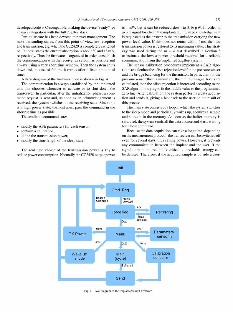
A flow diagram of the firmware code is shown in Fig. 4.The communication is always established by the implanted
nit that chooses whenever to activate or to shut down theransceiver. In particular, after the initialization phase, a com-
and request is sent and, as soon as an acknowledgement iseceived, the system switches to the receiving state. Since thiss a high power state, the host must pass the command in thehortest time as possible.
The available commands are:
modify the AFE parameters for each sensor,perform a calibration,define the transmission power,
modify the time length of the sleep state.The real time choice of the transmission power is key toeduce power consumption. Normally the CC2420 output power
easb
Fig. 4. Flow diagram of the im
ators A 142 (2008) 369–378 373
s 1 mW, but it can be reduced down to 3.16 �W. In order tovoid signal loss from the implanted unit, an acknowledgements requested as the answer to the transmission carrying the newower level value. If this does not return within 4 ms, then theransmission power is restored to its maximum value. This strat-gy was used during the in vivo test described in Section 3o estimate the lowest power threshold required for a reliableommunication from the implanted ZigBee system.
The sensor calibration procedures implement a SAR algo-ithm to calculate the offset rejection level for the pressure sensornd the bridge balancing for the thermistor. In particular, for theressure sensor, the maximum and the minimum signal levels arealculated, then the offset rejection is increased according to theAR algorithm, trying to fit the middle value to the programmedero line. After calibration, the system performs a data acquisi-ion and sends it, giving a feedback to the user on the result ofhis process.
The main state consists of a loop in which the system switcheso the sleep mode and periodically wakes up, acquires a samplend stores it in the memory. As soon as the buffer memory isaturated, the system sends all the data at once and starts waitingor a host command.
Because the data acquisition can take a long time, dependingn the measurement protocol, the transceiver can be switched off
ven for several days, thus saving power. However, it preventsny communication between the implant and the user. If theignal to be monitored is life critical, a thresholds strategy cane defined. Therefore, if the acquired sample is outside a user-plantable unit firmware.
3 d Actu
dbf
o
2
pwhbtps
dahia
(ctt
3
pt
rAsa
iatcrBd
uaoie
pwoomv
rfvv
Fa
74 P. Valdastri et al. / Sensors an
efined range, then the system immediately transmits all theuffer and establishes a communication with the host, allowingor the user intervention.
The described firmware requires just 12.5 kB, including bothf the transceiver routines and the AFE controls.
.2. Receiver system and GUI
Although the best solution for the receiver is probably aortable version powered by rechargeable batteries and providedith large memory and PC interface, in the present study a fixedost was implemented. The host must drive the implantable unity sending it the proper commands and by retrieving data whenhe implantable unit has them ready. Moreover, the host musterform all the communications as fast as possible in order toave battery life of the implantable unit.
For better time efficiency, the CC2420 used for the host isriven by a �C with a dedicated firmware and not directly byPC. A Pixie board has been used also at the host side, and itas been linked to the PC trough the serial port. The �C locatedn the host board is programmed to bridge the PC user interfacend the implanted unit.
A GUI has been implemented using Labview Express 7National Instruments, USA). This allows the user to input theommands to be sent to the implantable unit and to know whenhey have been received. Furthermore, it can display and storehe data acquired by the implant for off-line processing.
. Experimental results
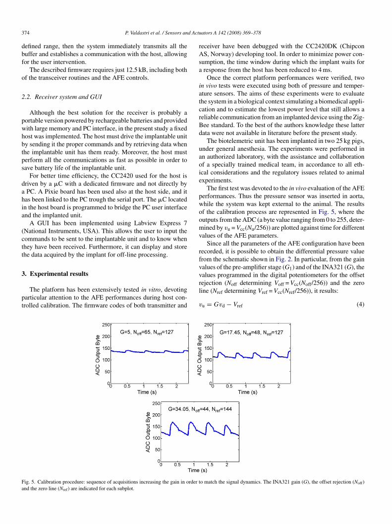
The platform has been extensively tested in vitro, devotingarticular attention to the AFE performances during host con-rolled calibration. The firmware codes of both transmitter and
rl
v
ig. 5. Calibration procedure: sequence of acquisitions increasing the gain in order tnd the zero line (Nref) are indicated for each subplot.
ators A 142 (2008) 369–378
eceiver have been debugged with the CC2420DK (ChipconS, Norway) developing tool. In order to minimize power con-
umption, the time window during which the implant waits forresponse from the host has been reduced to 4 ms.
Once the correct platform performances were verified, twon vivo tests were executed using both of pressure and temper-ture sensors. The aims of these experiments were to evaluatehe system in a biological context simulating a biomedical appli-ation and to estimate the lowest power level that still allows aeliable communication from an implanted device using the Zig-ee standard. To the best of the authors knowledge these latterata were not available in literature before the present study.
The biotelemetric unit has been implanted in two 25 kg pigs,nder general anesthesia. The experiments were performed inn authorized laboratory, with the assistance and collaborationf a specially trained medical team, in accordance to all eth-cal considerations and the regulatory issues related to animalxperiments.
The first test was devoted to the in vivo evaluation of the AFEerformances. Thus the pressure sensor was inserted in aorta,hile the system was kept external to the animal. The resultsf the calibration process are represented in Fig. 5, where theutputs from the ADC (a byte value ranging from 0 to 255, deter-ined by vu = Vcc(Nu/256)) are plotted against time for different
alues of the AFE parameters.Since all the parameters of the AFE configuration have been
ecorded, it is possible to obtain the differential pressure valuerom the schematic shown in Fig. 2. In particular, from the gainalues of the pre-amplifier stage (G1) and of the INA321 (G), thealues programmed in the digital potentiometers for the offset
ejection (Noff determining Voff = Vcc(Noff/256)) and the zeroine (Nref determining Vref = Vcc(Nref/256)), it results:u = Gvd − Vref (4)
o match the signal dynamics. The INA321 gain (G), the offset rejection (Noff)
d Actu
w
v
wSid
N
a
p
r
iAmci
u(th(irita
apcop
fqngmbc
srs[tfioIif
e3blb
I
waslcw
P. Valdastri et al. / Sensors an
ith vd as the differential input of INA321:
d = G1vps = G1Sppd (5)
here vps is the bridge output of the pressure sensor,
p = 97.6 × 10⁻⁶·Vcc is the pressure sensor sensitivity and pds the differential pressure. Thus the ADC output byte can beerived as
u = GG1Sppd256
Vcc− Nref (6)
nd
d = Nu − Nref
GG1Sp(256/Vcc)(7)
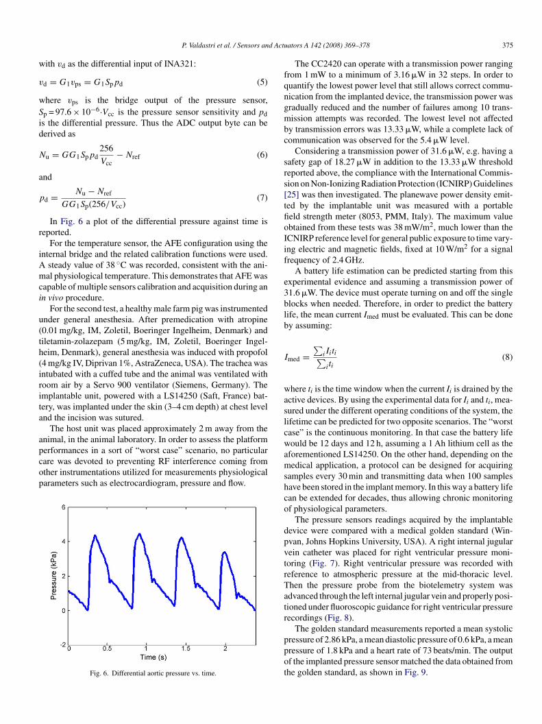
In Fig. 6 a plot of the differential pressure against time iseported.
For the temperature sensor, the AFE configuration using thenternal bridge and the related calibration functions were used.
steady value of 38 ◦C was recorded, consistent with the ani-al physiological temperature. This demonstrates that AFE was
apable of multiple sensors calibration and acquisition during ann vivo procedure.
For the second test, a healthy male farm pig was instrumentednder general anesthesia. After premedication with atropine0.01 mg/kg, IM, Zoletil, Boeringer Ingelheim, Denmark) andiletamin-zolazepam (5 mg/kg, IM, Zoletil, Boeringer Ingel-eim, Denmark), general anesthesia was induced with propofol4 mg/kg IV, Diprivan 1%, AstraZeneca, USA). The trachea wasntubated with a cuffed tube and the animal was ventilated withoom air by a Servo 900 ventilator (Siemens, Germany). Themplantable unit, powered with a LS14250 (Saft, France) bat-ery, was implanted under the skin (3–4 cm depth) at chest levelnd the incision was sutured.
The host unit was placed approximately 2 m away from thenimal, in the animal laboratory. In order to assess the platform
erformances in a sort of “worst case” scenario, no particularare was devoted to preventing RF interference coming fromther instrumentations utilized for measurements physiologicalarameters such as electrocardiogram, pressure and flow.Fig. 6. Differential aortic pressure vs. time.
amshco
dpvtrTatr
ppot
ators A 142 (2008) 369–378 375
The CC2420 can operate with a transmission power rangingrom 1 mW to a minimum of 3.16 �W in 32 steps. In order touantify the lowest power level that still allows correct commu-ication from the implanted device, the transmission power wasradually reduced and the number of failures among 10 trans-ission attempts was recorded. The lowest level not affected
y transmission errors was 13.33 �W, while a complete lack ofommunication was observed for the 5.4 �W level.
Considering a transmission power of 31.6 �W, e.g. having aafety gap of 18.27 �W in addition to the 13.33 �W thresholdeported above, the compliance with the International Commis-ion on Non-Ionizing Radiation Protection (ICNIRP) Guidelines25] was then investigated. The planewave power density emit-ed by the implantable unit was measured with a portableeld strength meter (8053, PMM, Italy). The maximum valuebtained from these tests was 38 mW/m2, much lower than theCNIRP reference level for general public exposure to time vary-ng electric and magnetic fields, fixed at 10 W/m2 for a signalrequency of 2.4 GHz.
A battery life estimation can be predicted starting from thisxperimental evidence and assuming a transmission power of1.6 �W. The device must operate turning on and off the singlelocks when needed. Therefore, in order to predict the batteryife, the mean current Imed must be evaluated. This can be doney assuming:
med =∑
iIiti∑iti
(8)
here ti is the time window when the current Ii is drained by thective devices. By using the experimental data for Ii and ti, mea-ured under the different operating conditions of the system, theifetime can be predicted for two opposite scenarios. The “worstase” is the continuous monitoring. In that case the battery lifeould be 12 days and 12 h, assuming a 1 Ah lithium cell as the
forementioned LS14250. On the other hand, depending on theedical application, a protocol can be designed for acquiring
amples every 30 min and transmitting data when 100 samplesave been stored in the implant memory. In this way a battery lifean be extended for decades, thus allowing chronic monitoringf physiological parameters.
The pressure sensors readings acquired by the implantableevice were compared with a medical golden standard (Win-van, Johns Hopkins University, USA). A right internal jugularein catheter was placed for right ventricular pressure moni-oring (Fig. 7). Right ventricular pressure was recorded witheference to atmospheric pressure at the mid-thoracic level.hen the pressure probe from the biotelemetry system wasdvanced through the left internal jugular vein and properly posi-ioned under fluoroscopic guidance for right ventricular pressureecordings (Fig. 8).
The golden standard measurements reported a mean systolic
ressure of 2.86 kPa, a mean diastolic pressure of 0.6 kPa, a meanressure of 1.8 kPa and a heart rate of 73 beats/min. The outputf the implanted pressure sensor matched the data obtained fromhe golden standard, as shown in Fig. 9.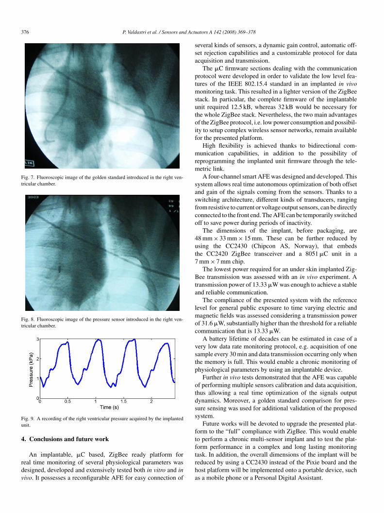
376 P. Valdastri et al. / Sensors and Actu
Fig. 7. Fluoroscopic image of the golden standard introduced in the right ven-tricular chamber.
Fig. 8. Fluoroscopic image of the pressure sensor introduced in the right ven-tricular chamber.
Fu
4
rdv
ssa
ptmsutoif
mrm
sasfco
4ut7
Bta
lmoc
vstp
otdss
ftf
ig. 9. A recording of the right ventricular pressure acquired by the implantednit.
. Conclusions and future work
An implantable, �C based, ZigBee ready platform foreal time monitoring of several physiological parameters wasesigned, developed and extensively tested both in vitro and inivo. It possesses a reconfigurable AFE for easy connection of
trha
ators A 142 (2008) 369–378
everal kinds of sensors, a dynamic gain control, automatic off-et rejection capabilities and a customizable protocol for datacquisition and transmission.
The �C firmware sections dealing with the communicationrotocol were developed in order to validate the low level fea-ures of the IEEE 802.15.4 standard in an implanted in vivo
onitoring task. This resulted in a lighter version of the ZigBeetack. In particular, the complete firmware of the implantablenit required 12.5 kB, whereas 32 kB would be necessary forhe whole ZigBee stack. Nevertheless, the two main advantagesf the ZigBee protocol, i.e. low power consumption and possibil-ty to setup complex wireless sensor networks, remain availableor the presented platform.
High flexibility is achieved thanks to bidirectional com-unication capabilities, in addition to the possibility of
eprogramming the implanted unit firmware through the tele-etric link.A four-channel smart AFE was designed and developed. This
ystem allows real time autonomous optimization of both offsetnd gain of the signals coming from the sensors. Thanks to awitching architecture, different kinds of transducers, rangingrom resistive to current or voltage output sensors, can be directlyonnected to the front end. The AFE can be temporarily switchedff to save power during periods of inactivity.
The dimensions of the implant, before packaging, are8 mm × 33 mm × 15 mm. These can be further reduced bysing the CC2430 (Chipcon AS, Norway), that embedshe CC2420 ZigBee transceiver and a 8051 �C unit in amm × 7 mm chip.
The lowest power required for an under skin implanted Zig-ee transmission was assessed with an in vivo experiment. A
ransmission power of 13.33 �W was enough to achieve a stablend reliable communication.
The compliance of the presented system with the referenceevel for general public exposure to time varying electric and
agnetic fields was assessed considering a transmission powerf 31.6 �W, substantially higher than the threshold for a reliableommunication that is 13.33 �W.
A battery lifetime of decades can be estimated in case of aery low data rate monitoring protocol, e.g. acquisition of oneample every 30 min and data transmission occurring only whenhe memory is full. This would enable a chronic monitoring ofhysiological parameters by using an implantable device.
Further in vivo tests demonstrated that the AFE was capablef performing multiple sensors calibration and data acquisition,hus allowing a real time optimization of the signals outputynamics. Moreover, a golden standard comparison for pres-ure sensing was used for additional validation of the proposedystem.
Future works will be devoted to upgrade the presented plat-orm to the “full” compliance with ZigBee. This would enableo perform a chronic multi-sensor implant and to test the plat-orm performance in a complex and long lasting monitoring
ask. In addition, the overall dimensions of the implant will beeduced by using a CC2430 instead of the Pixie board and theost platform will be implemented onto a portable device, suchs a mobile phone or a Personal Digital Assistant.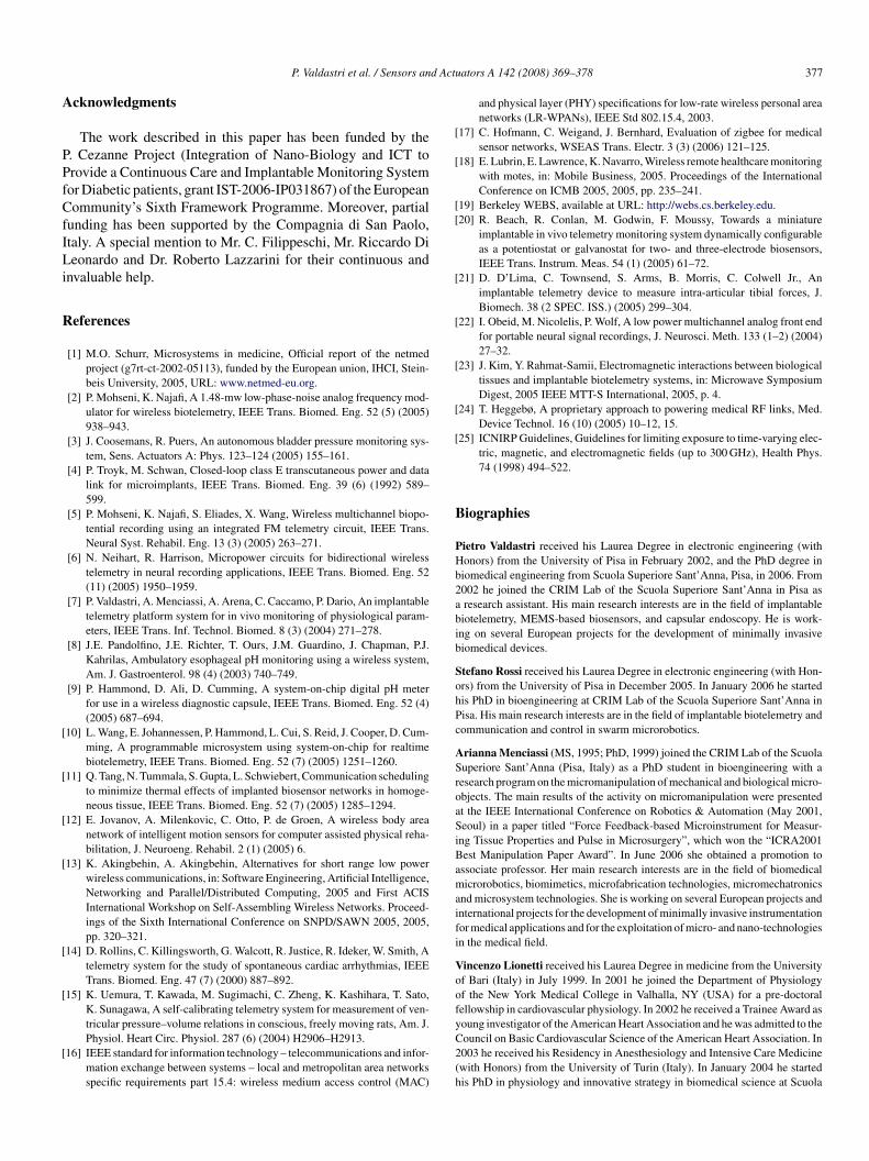
d Actu
A
PPfCfILi
R
[
[
[
[
[
[
[
[
[
[[
[
[
[
[
[
B
PHb2abib
SohPc
ASroaSiBamaifi
Voof
P. Valdastri et al. / Sensors an
cknowledgments
The work described in this paper has been funded by the. Cezanne Project (Integration of Nano-Biology and ICT torovide a Continuous Care and Implantable Monitoring Systemor Diabetic patients, grant IST-2006-IP031867) of the Europeanommunity’s Sixth Framework Programme. Moreover, partial
unding has been supported by the Compagnia di San Paolo,taly. A special mention to Mr. C. Filippeschi, Mr. Riccardo Dieonardo and Dr. Roberto Lazzarini for their continuous and
nvaluable help.
eferences
[1] M.O. Schurr, Microsystems in medicine, Official report of the netmedproject (g7rt-ct-2002-05113), funded by the European union, IHCI, Stein-beis University, 2005, URL: www.netmed-eu.org.
[2] P. Mohseni, K. Najafi, A 1.48-mw low-phase-noise analog frequency mod-ulator for wireless biotelemetry, IEEE Trans. Biomed. Eng. 52 (5) (2005)938–943.
[3] J. Coosemans, R. Puers, An autonomous bladder pressure monitoring sys-tem, Sens. Actuators A: Phys. 123–124 (2005) 155–161.
[4] P. Troyk, M. Schwan, Closed-loop class E transcutaneous power and datalink for microimplants, IEEE Trans. Biomed. Eng. 39 (6) (1992) 589–599.
[5] P. Mohseni, K. Najafi, S. Eliades, X. Wang, Wireless multichannel biopo-tential recording using an integrated FM telemetry circuit, IEEE Trans.Neural Syst. Rehabil. Eng. 13 (3) (2005) 263–271.
[6] N. Neihart, R. Harrison, Micropower circuits for bidirectional wirelesstelemetry in neural recording applications, IEEE Trans. Biomed. Eng. 52(11) (2005) 1950–1959.
[7] P. Valdastri, A. Menciassi, A. Arena, C. Caccamo, P. Dario, An implantabletelemetry platform system for in vivo monitoring of physiological param-eters, IEEE Trans. Inf. Technol. Biomed. 8 (3) (2004) 271–278.
[8] J.E. Pandolfino, J.E. Richter, T. Ours, J.M. Guardino, J. Chapman, P.J.Kahrilas, Ambulatory esophageal pH monitoring using a wireless system,Am. J. Gastroenterol. 98 (4) (2003) 740–749.
[9] P. Hammond, D. Ali, D. Cumming, A system-on-chip digital pH meterfor use in a wireless diagnostic capsule, IEEE Trans. Biomed. Eng. 52 (4)(2005) 687–694.
10] L. Wang, E. Johannessen, P. Hammond, L. Cui, S. Reid, J. Cooper, D. Cum-ming, A programmable microsystem using system-on-chip for realtimebiotelemetry, IEEE Trans. Biomed. Eng. 52 (7) (2005) 1251–1260.
11] Q. Tang, N. Tummala, S. Gupta, L. Schwiebert, Communication schedulingto minimize thermal effects of implanted biosensor networks in homoge-neous tissue, IEEE Trans. Biomed. Eng. 52 (7) (2005) 1285–1294.
12] E. Jovanov, A. Milenkovic, C. Otto, P. de Groen, A wireless body areanetwork of intelligent motion sensors for computer assisted physical reha-bilitation, J. Neuroeng. Rehabil. 2 (1) (2005) 6.
13] K. Akingbehin, A. Akingbehin, Alternatives for short range low powerwireless communications, in: Software Engineering, Artificial Intelligence,Networking and Parallel/Distributed Computing, 2005 and First ACISInternational Workshop on Self-Assembling Wireless Networks. Proceed-ings of the Sixth International Conference on SNPD/SAWN 2005, 2005,pp. 320–321.
14] D. Rollins, C. Killingsworth, G. Walcott, R. Justice, R. Ideker, W. Smith, Atelemetry system for the study of spontaneous cardiac arrhythmias, IEEETrans. Biomed. Eng. 47 (7) (2000) 887–892.
15] K. Uemura, T. Kawada, M. Sugimachi, C. Zheng, K. Kashihara, T. Sato,K. Sunagawa, A self-calibrating telemetry system for measurement of ven-
tricular pressure–volume relations in conscious, freely moving rats, Am. J.Physiol. Heart Circ. Physiol. 287 (6) (2004) H2906–H2913.16] IEEE standard for information technology – telecommunications and infor-mation exchange between systems – local and metropolitan area networksspecific requirements part 15.4: wireless medium access control (MAC)
yC2(h
ators A 142 (2008) 369–378 377
and physical layer (PHY) specifications for low-rate wireless personal areanetworks (LR-WPANs), IEEE Std 802.15.4, 2003.
17] C. Hofmann, C. Weigand, J. Bernhard, Evaluation of zigbee for medicalsensor networks, WSEAS Trans. Electr. 3 (3) (2006) 121–125.
18] E. Lubrin, E. Lawrence, K. Navarro, Wireless remote healthcare monitoringwith motes, in: Mobile Business, 2005. Proceedings of the InternationalConference on ICMB 2005, 2005, pp. 235–241.
19] Berkeley WEBS, available at URL: http://webs.cs.berkeley.edu.20] R. Beach, R. Conlan, M. Godwin, F. Moussy, Towards a miniature
implantable in vivo telemetry monitoring system dynamically configurableas a potentiostat or galvanostat for two- and three-electrode biosensors,IEEE Trans. Instrum. Meas. 54 (1) (2005) 61–72.
21] D. D’Lima, C. Townsend, S. Arms, B. Morris, C. Colwell Jr., Animplantable telemetry device to measure intra-articular tibial forces, J.Biomech. 38 (2 SPEC. ISS.) (2005) 299–304.
22] I. Obeid, M. Nicolelis, P. Wolf, A low power multichannel analog front endfor portable neural signal recordings, J. Neurosci. Meth. 133 (1–2) (2004)27–32.
23] J. Kim, Y. Rahmat-Samii, Electromagnetic interactions between biologicaltissues and implantable biotelemetry systems, in: Microwave SymposiumDigest, 2005 IEEE MTT-S International, 2005, p. 4.
24] T. Heggebø, A proprietary approach to powering medical RF links, Med.Device Technol. 16 (10) (2005) 10–12, 15.
25] ICNIRP Guidelines, Guidelines for limiting exposure to time-varying elec-tric, magnetic, and electromagnetic fields (up to 300 GHz), Health Phys.74 (1998) 494–522.
iographies
ietro Valdastri received his Laurea Degree in electronic engineering (withonors) from the University of Pisa in February 2002, and the PhD degree iniomedical engineering from Scuola Superiore Sant’Anna, Pisa, in 2006. From002 he joined the CRIM Lab of the Scuola Superiore Sant’Anna in Pisa asresearch assistant. His main research interests are in the field of implantableiotelemetry, MEMS-based biosensors, and capsular endoscopy. He is work-ng on several European projects for the development of minimally invasiveiomedical devices.
tefano Rossi received his Laurea Degree in electronic engineering (with Hon-rs) from the University of Pisa in December 2005. In January 2006 he startedis PhD in bioengineering at CRIM Lab of the Scuola Superiore Sant’Anna inisa. His main research interests are in the field of implantable biotelemetry andommunication and control in swarm microrobotics.
rianna Menciassi (MS, 1995; PhD, 1999) joined the CRIM Lab of the Scuolauperiore Sant’Anna (Pisa, Italy) as a PhD student in bioengineering with aesearch program on the micromanipulation of mechanical and biological micro-bjects. The main results of the activity on micromanipulation were presentedt the IEEE International Conference on Robotics & Automation (May 2001,eoul) in a paper titled “Force Feedback-based Microinstrument for Measur-
ng Tissue Properties and Pulse in Microsurgery”, which won the “ICRA2001est Manipulation Paper Award”. In June 2006 she obtained a promotion tossociate professor. Her main research interests are in the field of biomedicalicrorobotics, biomimetics, microfabrication technologies, micromechatronics
nd microsystem technologies. She is working on several European projects andnternational projects for the development of minimally invasive instrumentationor medical applications and for the exploitation of micro- and nano-technologiesn the medical field.
incenzo Lionetti received his Laurea Degree in medicine from the Universityf Bari (Italy) in July 1999. In 2001 he joined the Department of Physiologyf the New York Medical College in Valhalla, NY (USA) for a pre-doctoralellowship in cardiovascular physiology. In 2002 he received a Trainee Award as
oung investigator of the American Heart Association and he was admitted to theouncil on Basic Cardiovascular Science of the American Heart Association. In003 he received his Residency in Anesthesiology and Intensive Care Medicinewith Honors) from the University of Turin (Italy). In January 2004 he startedis PhD in physiology and innovative strategy in biomedical science at Scuola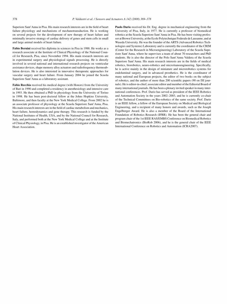
3 d Actu
Sfoma
FrciialvS
FoiiBaHhNIoH
PUrsWn(rsSrhemonmnaoiE
78 P. Valdastri et al. / Sensors an
uperiore Sant’Anna in Pisa. His main research interests are in the field of heartailure physiology and mechanisms of mechanotransduction. He is workingn several projects for the development of new therapy of heart failure andinimally invasive strategy of cardiac delivery of genes and stem cells in small
nd large animal models of heart failure.
abio Bernini received his diploma in sciences in Pisa in 1988. He works as aesearch associate at the Institute of Clinical Physiology of the National Coun-il for Research, Pisa, since November 1994. His main research interests aren experimental surgery and physiological signals processing. He is directlynvolved in several national and international research projects on ventricularssistance devices, shape memory alloy actuators and radiofrequency thermoab-ation devices. He is also interested in innovative therapeutic approaches forascular surgery and heart failure. From January 2004 he joined the Scuolauperiore Sant’Anna as a laboratory assistant.
abio Recchia received his medical degree (with Honors) from the Universityf Bari in 1990 and completed a residency in anesthesiology and intensive caren 1993. He then obtained a PhD in physiology from the University of Torinon 1998. He has been post-doctoral fellow at the Johns Hopkins University,altimore, and then faculty at the New York Medical College. From 2002 he isn associate professor of physiology at the Scuola Superiore Sant’Anna, Pisa.is main research interests are in the field of cardiac metabolism and mechanics,
eart failure, hemodynamics and gene therapy. This research is funded by theational Institutes of Health, USA, and by the National Council for Research,taly, and performed both at the New York Medical College and at the Institutef Clinical Physiology, in Pisa. He is an established investigator of the Americaneart Association.
EFpaI
ators A 142 (2008) 369–378
aolo Dario received his Dr. Eng. degree in mechanical engineering from theniversity of Pisa, Italy, in 1977. He is currently a professor of biomedical
obotics at the Scuola Superiore Sant’Anna in Pisa. He has been visiting profes-or at Brown University, at the Ecole Polytechnique Federale de Lausanne, and ataseda University. He was the founder of the ARTS (Advanced Robotics Tech-
ologies and Systems) Laboratory and is currently the coordinator of the CRIMCenter for the Research in Microengineering) Laboratory of the Scuola Supe-iore Sant’Anna, where he supervises a team of about 70 researchers and PhDtudents. He is also the director of the Polo Sant’Anna Valdera of the Scuolauperiore Sant’Anna. His main research interests are in the fields of medicalobotics, biorobotics, neuro-robotics and micro/nanoengineering. Specifically,e is active mainly in the design of miniature and microrobotics systems forndoluminal surgery, and in advanced prosthetics. He is the coordinator ofany national and European projects, the editor of two books on the subject
f robotics, and the author of more than 200 scientific papers (90 on ISI jour-als). He is editor-in-chief, associate editor and member of the Editorial Board ofany international journals. He has been a plenary invited speaker in many inter-
ational conferences. Prof. Dario has served as president of the IEEE Roboticsnd Automation Society in the years 2002–2003, and he is currently co-chairf the Technical Committees on Bio-robotics of the same society. Prof. Darios an IEEE fellow, a fellow of the European Society on Medical and Biologicalngineering, and a recipient of many honors and awards, such as the Joseph
ngelberger Award. He is also a member of the Board of the Internationaloundation of Robotics Research (IFRR). He has been the general chair androgram chair of the 1st IEEE RAS/EMBS Conference on Biomedical Roboticsnd Biomechatronics (BioRob 2006), and he is the general chair of the IEEEnternational Conference on Robotics and Automation (ICRA2007).
Related Documents