An IBM Rational Approach to the Department of Defense Architecture Framework (DoDAF) January 2006 An IBM Rational Approach to the Department of Defense Architecture Framework (DoDAF) Chris Widney Senior Technical Services Specialist Rational Brand Services IBM Software Group

An IBM Rational Approach to the Department of Defense ...
Nov 11, 2014
Welcome message from author
This document is posted to help you gain knowledge. Please leave a comment to let me know what you think about it! Share it to your friends and learn new things together.
Transcript
An IBM Rational Approach to the Department of Defense Architecture Framework (DoDAF)January 2006
An IBM Rational Approach to the Department of Defense Architecture Framework (DoDAF)
Chris Widney Senior Technical Services Specialist Rational Brand Services IBM Software Group

An IBM Rational Approach to the Department of Defense Architecture Framework (DoDAF)Page 2
“The Department of Defense (DoD) Architecture Framework (DoDAF) defines a common approach for DoD architecture description development, presentation, and integration for both warfighting operations and business operations and processes. The Framework is intended to ensure that architecture descriptions can be compared and related across organizational boundaries, including Joint and multinational boundaries.” (DoD Architectural Framework, Version 1.0, 15 August 2003)
DoDAF’s primary objective is to produce a standardized report describing a complex systems architecture. Operational decision-makers can then use this report in the DoD to compare the architecture of alternative systems and manage the evolution of existing systems. The report consists of views that describe a systems architecture well enough to justify procurement of the system to DoD management and the Congressional Budget Office (CBO).
Companies doing business with the DoD are tasked to comply with some or all of the DoDAF as they propose their systems. In this paper, we discuss an approach to modeling complex systems architecture in conjunction with constructing appropriate DoDAF views. While exploring DoDAF semantics, we leverage the architectural model, Unified Modeling Language (UML) notation, and IBM Rational tooling to support the production of complete, correct and consistent DoDAF views of a well-formed enterprise architecture model.
Background
Architecting complex systems and operational enterprises demands an
extraordinary capacity to understand and manage complex relationships. A
thorough understanding of the enterprise’s architecture is crucial to effective
design, implementation, deployment, and maintenance of evolving systems.
2 Background
4 Leveraging IBM’s Software
Development Platform for DoDAF
5 DoDAF Syntax and Semantics
6 Best Practices for Complex
Systems Development
8 DoDAF Model Organization
9 DoDAF View Relationships
12 All Views Products
13 Operational View Products
28 Systems View Products
41 Technical Standards View
43 Conclusion
44 References
Contents
An IBM Rational Approach to the Department of Defense Architecture Framework (DoDAF)Page 3
A complete, consistent model of that architecture is the key to mitigating risk
and managing the systems’ complexity. DoDAF content provides us with a
“window” into the architecture that we can leverage as we incrementally define
the system.
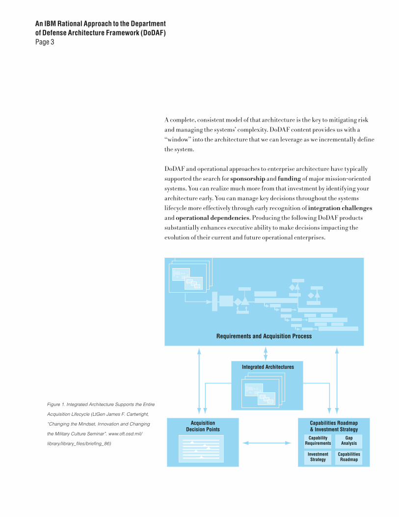
DoDAF and operational approaches to enterprise architecture have typically
supported the search for sponsorship and funding of major mission-oriented
systems. You can realize much more from that investment by identifying your
architecture early. You can manage key decisions throughout the systems
lifecycle more effectively through early recognition of integration challenges and operational dependencies. Producing the following DoDAF products
substantially enhances executive ability to make decisions impacting the
evolution of their current and future operational enterprises.
Figure 1. Integrated Architecture Supports the Entire
Acquisition Lifecycle (LtGen James F. Cartwright,
“Changing the Mindset, Innovation and Changing
the Military Culture Seminar”. www.oft.osd.mil/
library/library_files/briefing_86)

An IBM Rational Approach to the Department of Defense Architecture Framework (DoDAF)Page 4
Leveraging IBM’s Software Development Platform for DoDAF
The IBM Rational approach to DoDAF is comprehensive. Our total solution
incorporates an integrated toolset, a proven systems engineering process, and
a robust enablement capability designed to facilitate discovery, description,
implementation, and evolution of the complex enterprise architecture
associated with DoD’s operational missions.
Our tooling builds upon capabilities supported by the optional, downloadable
DoDAF feature for the the IBM Rational Eclipse-based modeling solution family
of tools (IBM Rational Software Architect, IBM Rational Software Modeler and
IBM Rational Systems Developer). This paper’s discussion assumes that the
optional DoDAF feature is being implemented. Integrations with IBM Rational
RequisitePro® for requirements management, IBM Rational ClearCase® for
configuration management, IBM Rational ClearQuest® for change management,
and other IBM Rational products empower the entire systems development
team. Extended capabilities and plug-ins provided by Ready for Rational
Partners can further enhance capability, such as with SysML modeling and state-
machine-based executable models.
Strictly speaking, the DoDAF is all about content. However, the optimal approach
to DoDAF compliance should not require divergent effort from the primary
objective of developing the system. The IBM Rational approach incorporates
DoDAF product generation into the overall architectural effort, allowing the
DoDAF views to represent an evolving enterprise architecture that is consistent with, and traceable to the systems necessary to implement that architecture.
As with any complex activity, learning to create and maintain an enterprise
architecture using DoDAF requires skilled application of systems engineering
and DoDAF-specific knowledge. IBM Rational is ideally positioned to offer
enablement services to optimize your architectural efforts. The following
material introduces you to DoDAF, and shows how you can address it within
the context of developing an enterprise architecture.

An IBM Rational Approach to the Department of Defense Architecture Framework (DoDAF)Page 5
DoDAF Syntax and Semantics
· DoDAF focuses on relationships. The DoDAF content focuses on relationships
between significant architectural elements of the operational enterprise. The
model’s core semantic elements are nodes, needlines, services, and information
exchanges. Collectively, these elements describe the structure and allocation of
significant behavior in the operational enterprise.
· Nodes – systems, actors and workers. The principle element of the DoDAF
is the node, which represents a logical or physical entity operating within the
enterprise, or operational environment. These entities could represent collections
of workers, systems or subsystems, within or outside the enterprise, whose role
is to interact in some manner with one or more elements of that enterprise.
An understanding of both the internally and externally visible characteristics
of these nodes provides the foundation for the architecture and design of this
system-of-systems, the operational enterprise. The architecture will tend to
focus more on the relationships between the nodes, while the design deals
more with the internal structure and behavior of the nodes. Accordingly,
the DoDAF’s primary objective and the benefit of architectural modeling of
the operational enterprise, is a characterization of the manner in which
nodes cooperate to fulfill the mission. In DoDAF, we deal with three types
of nodes: operational nodes, which are described in the operational view,
and reflect combinations of actors, workers and systems, systems which are
logical elements that implement the behavior of the operational nodes, and
system nodes, which represent physical elements or localities, that host logical
systems or subsystems.
An IBM Rational Approach to the Department of Defense Architecture Framework (DoDAF)Page 6
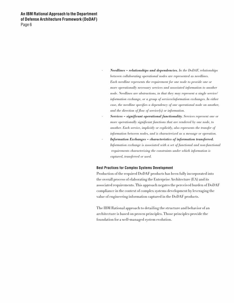
· Needlines – relationships and dependencies. In the DoDAF, relationships
between collaborating operational nodes are represented as needlines.
Each needline represents the requirement for one node to provide one or
more operationally necessary services and associated information to another
node. Needlines are abstractions, in that they may represent a single service/
information exchange, or a group of services/information exchanges. In either
case, the needline specifies a dependency of one operational node on another,
and the direction of flow of service(s) or information.
· Services – significant operational functionality. Services represent one or
more operationally significant functions that are rendered by one node, to
another. Each service, implicitly or explicitly, also represents the transfer of
information between nodes, and is characterized as a message or operation.
· Information Exchanges – characteristics of information transferred.
Information exchange is associated with a set of functional and non-functional
requirements characterizing the constraints under which information is
captured, transferred or used.
Best Practices for Complex Systems Development
Production of the required DoDAF products has been fully incorporated into
the overall process of elaborating the Enterprise Architecture (EA) and its
associated requirements. This approach negates the perceived burden of DoDAF
compliance in the context of complex systems development by leveraging the
value of engineering information captured in the DoDAF products.
The IBM Rational approach to detailing the structure and behavior of an
architecture is based on proven principles. Those principles provide the
foundation for a well-managed system evolution.
An IBM Rational Approach to the Department of Defense Architecture Framework (DoDAF)Page 7
· Decompose systems, not requirements. Develop each abstraction level
before proceeding to the next lower level. Elaborate use cases fully and
captured behavior explicitly. Be sure to consider not only the logical
architecture, but the physical/locality-oriented aspects of the architecture
as well. Discover and document the relationships between the logical and
physical architectures for each level of abstraction addressed. Iterate to the
next lower level of abstraction until the architecture is sufficiently captured
to meet the needs of the development organization
· Enable both separation and integration of concerns. Examine both black
box and white box views for each level of abstraction addressed. Strive for
balance between perspectives to avoid overcooking in either direction. Too
much separation results in functional decomposition and its associated
integration issues; too much emphasis on integration and you risk missing
important functional issues.
· Systems and components collaborate; so should development teams.
Developers of components and systems /subsystems that need to collaborate,
depend on thorough knowledge of dependencies. Without developer
collaboration, you increase the risk to successful integration.
· Specifications flow up and down the architecture. You should understand
the requirements at each level of abstraction, and use them to derive the
capabilities of the elements that collaborate at that level of abstraction.
· Base the lifecycle on removing risk and adding value. Minimize the
obstacles to success when the resources are there.
· Development organization should reflect product architecture. Optimal
application of development team skills calls for shifting responsibilities from
one role to another throughout iterations. Organizing teams with multiple
complementary skills provides for more management flexibility, and increases
the overall capabilities of individuals to the organization.
An IBM Rational Approach to the Department of Defense Architecture Framework (DoDAF)Page 8
Risk management drives the overall process for development of an enterprise
architecture. This enables a logical, systematic capture of the essential
architecture of a complex system. Rigorous application of an iterative process
and use of a standard notation (Unified Modeling Language or UML),results
in a comprehensive visual representation of multiple perspectives of system
structure and behavior, at successively lower levels of abstraction. Recursively
applying the process to the level of subsystems definition and internal design
results in a complete, consistent engineering model of the architecture.
This, in turn, provides a foundation for design, implementation, deployment,
management and controlled evolution of an enterprise or complex system.
DoDAF Model Organization
The DoDAF is a structured set of architectural information, organized
around views. The All Views (AV) products are intended to provide an
overall perspective of the subject system in the context of the operational
enterprise, and would address overarching concerns like CONOPS (Concept of
Operations), critical mission objectives and strategies, as well as an integrated
dictionary of architecturally significant terms. The Operational View (OV) focuses on externally visible structure and behavior of the subject system.
Operational nodes and their relationships are described and dependencies
reflecting mission requirements are identified, providing an overall context
for enterprise definition and evolution. Realization of internal structure
and behavior is the focus of the Systems View (SV), and incorporates a
rigorous allocation of functional and non-functional requirements (from the
Operational View) to both logical and physical system elements and interfaces.
Standards constraining the operational architecture of the enterprise are
reflected in the Technical Standards View (TV), and address both current
and future states of the system(s).
An IBM Rational Approach to the Department of Defense Architecture Framework (DoDAF)Page 9
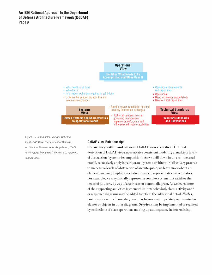
DoDAF View Relationships
Consistency within and between DoDAF views is critical. Optimal
derivation of DoDAF views necessitates consistent modeling at multiple levels
of abstraction (systems decomposition). As we drill down in an architectural
model, recursively applying a rigorous systems architecture discovery process
to successive levels of abstraction of an enterprise, we learn more about an
element, and may employ alternative means to represent its characteristics.
For example, we may initially represent a complex system that satisfies the
needs of its users, by way of a use-case or context diagram. As we learn more
of the supporting activities (system white-box behavior), class, activity and/
or sequence diagrams may be added to reflect the additional detail. Nodes,
portrayed as actors in one diagram, may be more appropriately represented as
classes or objects in other diagrams. Services may be implemented or realized
by collections of class operations making up a subsystem. In determining
Figure 2. Fundamental Linkages Between
the DoDAF Views (Department of Defense
Architecture Framework Working Group, “DoD
Architectural Framework”, Version 1.0, Volume I,
August 2003)
An IBM Rational Approach to the Department of Defense Architecture Framework (DoDAF)Page 10
how best to model each of the core DoDAF elements, we must first understand
the essential semantics underlying that element (along with any applicable
constraints) and then apply the appropriate notation, given the context of the
overall engineering effort. Context includes risk, complexity, tools, notation,
and objective(s) for the modeling effort.
The overall process of DoDAF view production is both iterative and incremental. As more breadth and depth of architectural information is captured, evolution of
the AV-1 and AV-2 progresses. Using the AV-1 as a foundation, the architectural
interactions of the operational enterprise and the subject system are examined,
resulting in discovery of the high-level interactions between the system and the
operational nodes. Full characterization of these high-level relationships is the
focus of the Operational View.
Only after we fully understand the external systems behavior (Operational
View), do we proceed with the elaboration of the Systems View. This is where we
begin to design and organize the internal behavior and subsystems interactions
that provide the foundation for full-scale development. At this point, we also
reconcile multiple viewpoints that allow us to deal with the necessary physical
and logical realization of operational behavior through joint realization
practices and use case flowdown.

An IBM Rational Approach to the Department of Defense Architecture Framework (DoDAF)Page 11
Checkpoints for Overall DoDAF Relationships between Products2
® Do OV-2 operational nodes map to operational activities in the OV-5 that are associated with those operational nodes?
® Do OV-2 needlines in the map to IERs (Information Exchange Requirements) in the OV-3?
® Are the OV-3 data elements of the IERs mapped to the IO Entities reflected in the OV-7?
® Do the OV-6a operational rules relate to the activity logic addressed in the OV-5?
® Are rules applicable to the OV-7 data captured in the OV-6a?
® Are rules applicable to the SV-4 contained in the SV-10a?
® Do OV-2 operational nodes map to systems identified in the SV-1 to support those nodes?
® Do OV-2 operational nodes map to system nodes identified in the SV-1 to support those nodes?
® Do OV-2 operational nodes map to interfaces identified in the SV-1 to support those nodes?
® Do OV-2 needlines map to interfaces identified in the SV-1 that support those needlines?
® Do interfaces in the SV-1 map to system data elements identified in the SV-6 and the system functionality identified in SV-4?
® Do SV-4 system operations map to the interfaces in SV-1?
® Do SV-4 system operations map to operational activities identified in the OV-5, and does the SV-5 document that relationship?
® Do SV-6 data exchanges map to the IERs of the OV-3?
® Do OV-2 operational nodes map to systems identified in the SV-1 to support those nodes?
® Does the SV-11 Physical Data model support the implementation of the OV-7 Logical Data model?
® Are the TV-1 standards and constraints mapped to the applicable SV-1,SV-2, SV-4, SV-6, OV-7, and SV-11 elements?
® Do the technology forecasts of the SV-9 and the standards forecasts of the TV-2 correlate/ trace to system evolution timelines and milestones of the SV-8?

An IBM Rational Approach to the Department of Defense Architecture Framework (DoDAF)Page 12
All Views Products
The following table briefly describes the All Views products and the order in
which you might create them following this process.
The DoDAF All Views (AV) products provide a summary of the environment
in which the subject systems are to be developed, deployed, and managed
during their evolution. The summary describes mission objectives, strategies,
operational concepts, the general context for operations and relevant terminology.
AV-1 Overview and Summary Information
The AV-1 is a textual summary of the operational environment and the mission
capabilities to be exercised in the context of the evolving systems. Focus is on
the subject system or enterprise in an operational context. Relevant Concepts
of Operations (CONOPS) and strategies are presented at a level of abstraction
appropriate to executive leadership, in order to facilitate decision making. The
content of the AV-1 represents the guidance or vision that reflects essential
business drivers and the need for the subject system under development.
The acquirer or development organization may prepare the AV-1, although, as
with all DoDAF view products, substantial interaction with Subject Matter Experts
(SMEs) will be required. In our approach, we produce the AV-1 document using
a standard word processing tool and associate (via a the document reference link)
with the model containing the visual DoDAF products.
Tool Tip: Create the AV-1 document
using the template by selecting the
AV-1 in the Rational’s Eclipse-based
modeling solutions DoDAF model,
clicking on the right mouse button,
and selecting DoDAF > AV-1
Product Title Description Representation Creation Order
AV-1
Overview and Summary Information
Textual document describing scope, purpose, intended users, operational environment for the subject system. Provide an overall understanding of the nature of the enterprise and how it interacts with the subject system. Supports the strategic vision for system usage
Model referenced text document
1
AV-2Integrated Dictionary Definitions for all terms used to describe the architecture.
Provide an set of standard reference terms to maintain consistency of meaning to all consumers of the architecture
Model resident, repository-based text Exportable to XML
Ongoing
An IBM Rational Approach to the Department of Defense Architecture Framework (DoDAF)Page 13
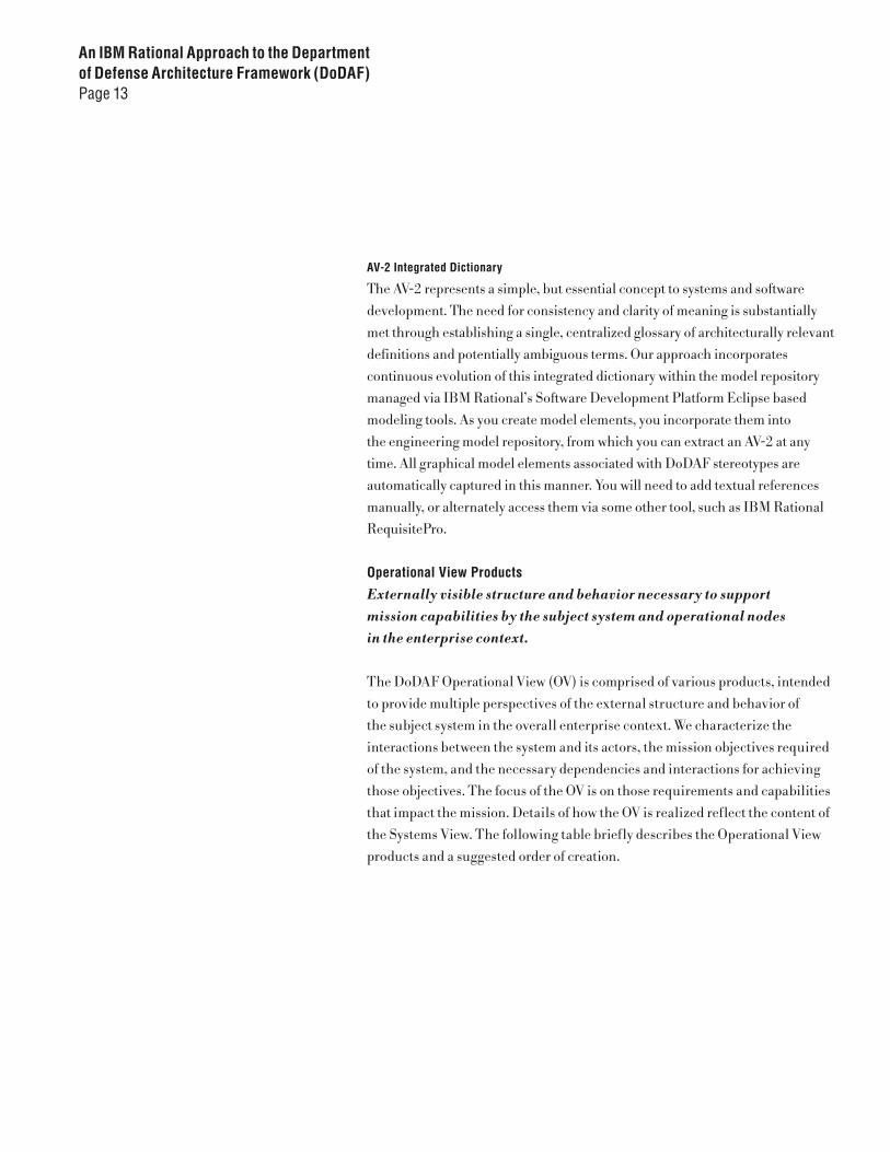
AV-2 Integrated Dictionary
The AV-2 represents a simple, but essential concept to systems and software
development. The need for consistency and clarity of meaning is substantially
met through establishing a single, centralized glossary of architecturally relevant
definitions and potentially ambiguous terms. Our approach incorporates
continuous evolution of this integrated dictionary within the model repository
managed via IBM Rational’s Software Development Platform Eclipse based
modeling tools. As you create model elements, you incorporate them into
the engineering model repository, from which you can extract an AV-2 at any
time. All graphical model elements associated with DoDAF stereotypes are
automatically captured in this manner. You will need to add textual references
manually, or alternately access them via some other tool, such as IBM Rational
RequisitePro.
Operational View Products
Externally visible structure and behavior necessary to support mission capabilities by the subject system and operational nodes in the enterprise context.
The DoDAF Operational View (OV) is comprised of various products, intended
to provide multiple perspectives of the external structure and behavior of
the subject system in the overall enterprise context. We characterize the
interactions between the system and its actors, the mission objectives required
of the system, and the necessary dependencies and interactions for achieving
those objectives. The focus of the OV is on those requirements and capabilities
that impact the mission. Details of how the OV is realized reflect the content of
the Systems View. The following table briefly describes the Operational View
products and a suggested order of creation.
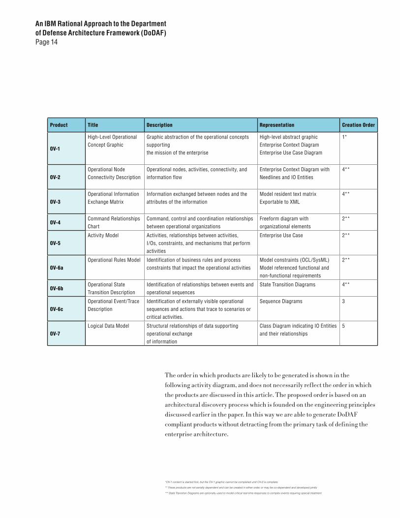
An IBM Rational Approach to the Department of Defense Architecture Framework (DoDAF)Page 14
The order in which products are likely to be generated is shown in the
following activity diagram, and does not necessarily reflect the order in which
the products are discussed in this article. The proposed order is based on an
architectural discovery process which is founded on the engineering principles
discussed earlier in the paper. In this way we are able to generate DoDAF
compliant products without detracting from the primary task of defining the
enterprise architecture.
Product Title Description Representation Creation Order
OV-1
High-Level Operational Concept Graphic
Graphic abstraction of the operational concepts supporting the mission of the enterprise
High-level abstract graphicEnterprise Context DiagramEnterprise Use Case Diagram
1*
OV-2Operational Node Connectivity Description
Operational nodes, activities, connectivity, and information flow
Enterprise Context Diagram with Needlines and IO Entities
4**
OV-3Operational Information Exchange Matrix
Information exchanged between nodes and the attributes of the information
Model resident text matrix Exportable to XML
4**
OV-4Command Relationships Chart
Command, control and coordination relationships between operational organizations
Freeform diagram with organizational elements
2**
OV-5Activity Model Activities, relationships between activities,
I/Os, constraints, and mechanisms that perform activities
Enterprise Use Case 2**
OV-6aOperational Rules Model Identification of business rules and process
constraints that impact the operational activitiesModel constraints (OCL/SysML)Model referenced functional and non-functional requirements
2**
OV-6bOperational State Transition Description
Identification of relationships between events and operational sequences
State Transition Diagrams 4**
OV-6cOperational Event/Trace Description
Identification of externally visible operational sequences and actions that trace to scenarios or critical activities.
Sequence Diagrams 3
OV-7Logical Data Model Structural relationships of data supporting
operational exchange of information
Class Diagram indicating IO Entities and their relationships
5
*OV-1 content is started first, but the OV-1 graphic cannot be completed until OV-2 is complete
** These products are not serially dependent and can be created in either order, or may be co-dependent and developed jointly
*** State Transition Diagrams are optionally used to model critical real-time responses to complex events requiring special treatment

An IBM Rational Approach to the Department of Defense Architecture Framework (DoDAF)Page 15
Figure 3. DoDAF AV and OV Product
Generation Process
An IBM Rational Approach to the Department of Defense Architecture Framework (DoDAF)Page 16
OV-1 High-level Operational Concept Graphic
The OV-1, in a clear and concise way, communicates the scope of the subject
system within the context of the operational enterprise. The graphical depiction
of the OV-1 is typically an artist-rendered product reflecting content derived
from multiple sources. The primary information sources for the OV-1 are the
AV-1 Overview and Summary document, an Operational Context Diagram,
and an Enterprise Use Case Diagram. We construct the Enterprise Use Case
Diagram starting with the subject system and identify any external systems and
organizational entities that interact with that system. We characterize these
interacting elements as actors. Use cases are then added to the diagram for each
operational goal or objective attributed to actors. Communicates stereotyped
associations are added, where appropriate.
Several actors/roles may collaborate within organizational elements in order to
meet mission needs. The aggregation of actors/roles to organizational elements
results in identification of operational nodes, which are captured using a class
diagram, designated the Operational Context Diagram. The interactions
between actors and the subject system become represented by the collective
interactions, or needlines between the operational nodes (actor aggregation)
and that system. The IO Entities associated with those actors transitively
become associated with the specified operational node. The Systems Architect
and applicable SMEs then collaborate with a graphic artist in rendering the
collective content of the above products in an OV-1 graphic, tailored for an
executive-level audience. This graphic will provide the foundation for the
structuring the externally visible architecture of the operational enterprise,
as it relates to the system under development. Content will evolve as further
information is captured during subsequent DoDAF product generation.
An IBM Rational Approach to the Department of Defense Architecture Framework (DoDAF)Page 17
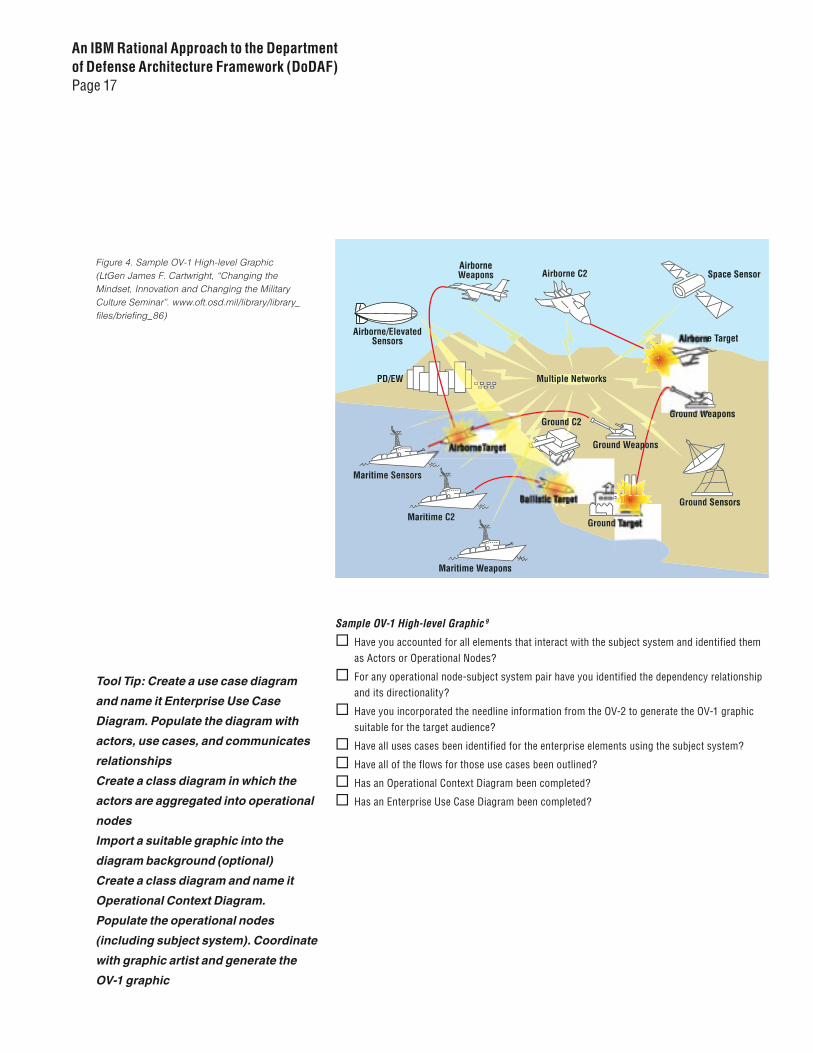
Sample OV-1 High-level Graphic 9
® Have you accounted for all elements that interact with the subject system and identified them as Actors or Operational Nodes?
® For any operational node-subject system pair have you identified the dependency relationship and its directionality?
® Have you incorporated the needline information from the OV-2 to generate the OV-1 graphic suitable for the target audience?
® Have all uses cases been identified for the enterprise elements using the subject system?
® Have all of the flows for those use cases been outlined?
® Has an Operational Context Diagram been completed?
® Has an Enterprise Use Case Diagram been completed?
Tool Tip: Create a use case diagram
and name it Enterprise Use Case
Diagram. Populate the diagram with
actors, use cases, and communicates
relationships
Create a class diagram in which the
actors are aggregated into operational
nodes
Import a suitable graphic into the
diagram background (optional)
Create a class diagram and name it
Operational Context Diagram.
Populate the operational nodes
(including subject system). Coordinate
with graphic artist and generate the
OV-1 graphic
Figure 4. Sample OV-1 High-level Graphic (LtGen James F. Cartwright, “Changing the Mindset, Innovation and Changing the Military Culture Seminar”. www.oft.osd.mil/library/library_files/briefing_86)
An IBM Rational Approach to the Department of Defense Architecture Framework (DoDAF)Page 18
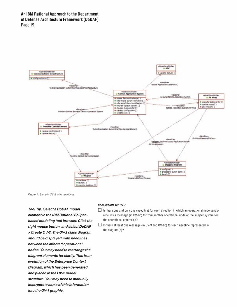
OV-2 Operational Node Connectivity Description
The OV-2 identifies and models critical operational dependencies between
operational nodes. The DoDAF defines these as needlines. There are two
primary approaches to determining needlines: 1) identify the nature of the
dialog represented in each communicates association in the Enterprise Use Case
Diagram, and specify a needline, directionally oriented so that the needline
is navigable from the consumer (for that relationship) to the supplier of the
service or information; 2) wait until detailing the use case flows and scenarios,
and capturing them in the OV-6c sequence diagrams, and then identify specific
object/role interactions, which can be “rolled up” to representative needlines.
Option 1 is a manual process, since some level of engineering/architectural
analysis is necessary. Option 2 allows us to leverage capabilities of IBM
Rational’s Eclipse-based modeling tools to automatically populate the needlines
(and OV-3 IERs) from content in manually produced sequence diagrams. This
approach has the additional advantage of guaranteeing consistency between OV-
2, OV-3, and OV-6c, since all are derived from identical model information.
A needline may represent many information exchanges or service dependencies.
Accordingly, once a needline has been identified between any two context
diagram elements, no other needlines, in the same direction, are appropriate
An IBM Rational Approach to the Department of Defense Architecture Framework (DoDAF)Page 19
Checkpoints for OV-2
® Is there one and only one (needline) for each direction in which an operational node sends/ receives a message (in OV-6c) to/from another operational node or the subject system for the operational enterprise?
® Is there at least one message (in OV-3 and OV-6c) for each needline represented in the diagram(s)?
Figure 5. Sample OV-2 with needlines
Tool Tip: Select a DoDAF model
element in the IBM Rational Eclipse-
based modeling tool browser. Click the
right mouse button, and select DoDAF
> Create OV-2. The OV-2 class diagram
should be displayed, with needlines
between the affected operational
nodes. You may need to rearrange the
diagram elements for clarity. This is an
evolution of the Enterprise Context
Diagram, which has been generated
and placed in the OV-2 model
structure. You may need to manually
incorporate some of this information
into the OV-1 graphic.

An IBM Rational Approach to the Department of Defense Architecture Framework (DoDAF)Page 20
Advanced Topic - Use of Collaborations to enhance relationship definition and capture of needlines.
UML 2.0 introduces a new classifier, the Collaboration. The semantics associated
with the Collaboration offer potential for characterizing relationships more
robustly. You can specify relationship roles, patterns, templates, and associated
parameters can be specified. You can also instantiate the information associated
with collaborations as collaboration occurrences, further specifying each
potential IER. Augmenting the minimal set of DoDAF representations with class
and composite structure diagrams (referencing collaborations and collaboration
occurrences, respectively), may provide utility. The UML Language Reference
Manual3 provides a thorough discussion of these UML elements.
OV-3 Operational Information Exchange Matrix
The OV-3 is a matrix of Information Exchange Requirements (IERs) that
collectively represent the needlines of the OV-2. The OV-3 is generated
automatically using the IBM Rational’s Eclipse-based modeling tool (by
sourcing the OV-6c content). Each matrix row represents an IER, which is
comprised of characteristics of the data transferred between roles/objects
in an interaction from the OV-6c sequence diagrams. The matrix identifies
a distinct IER for each pair of objects or roles that interact and exchange
information. Specific IER characteristics are typically associated with non-
functional requirements or design constraints. Each IER’s content represents
an instantiation of an IO Entity class (see discussion of IO Entities in section
covering OV-6c), where the attributes represent the data characteristics
required by the DoDAF. Accordingly, each information element in the
matrix should trace to the Logical Data Model, OV-7.
The OV-3 emphasizes the logical and operational characteristics of the
information exchanged. The product is not intended to provide exhaustive
capture of all details of information exchanged within the architecture, but as
a mechanism understand the most important aspects of significant exchanges.
An example of the information content from the DoDAF specification is
provided below. This content would typically trace to supplemental or non-
functional requirements.

An IBM Rational Approach to the Department of Defense Architecture Framework (DoDAF)Page 21
Needline Identifier
IER Identifier
Nature of Transaction Performance Attributes
Information Assurance Security
• Mission Scenario UJTL or METL• Transaction Type• Triggering Event• Interoperability Level Required• Criticality
• Periodicity• Timeliness
• Access Control• Availability• Confidentiality• Dissemination Control• Integrity
• Accountability• Protection (Type Name, Duration, Date)• Classification• Classification Caveat
Needline Identifier
IER Identifier
Information Element Description Producer Consumer
• Information Element Name and Identifier• Content• Scope• Accuracy• Language
• Sending Op Node Name and Identifier• Sending Op Activity Name and Identifier
• Receiving Op Node Name and Identifier• Receiving Op Activity Name and Identifier
Figure 6. Sample OV-3 Information Exchange Matrix
An IBM Rational Approach to the Department of Defense Architecture Framework (DoDAF)Page 22
Checkpoints for OV-3
® Have IO Entities been identified for each parameter specified in each inter-object message in OV-6c sequence diagrams?
® Have attributes been established for each IO Entity class, consistent with the guidance provided in volume II of the DoDAF specification?
® Is there an entry for each message in the OV-6c sequence diagrams indicating information passed as parameters?
® Is there at least one entry for each needline represented in the OV-2?
OV-4 Command Relationships Chart
The OV-4 models the relationships that exist between organizational entities
that affect the operational architecture of the enterprise and its systems. Specific
organizational elements are likely candidates for the roles (i.e., instantiations of
operational nodes) in the interaction diagrams comprising the OV-6c. The OV-4
is represented by a freeform diagram. Note: Some implementers have elected
to create this diagram but show little, if any, mapping between the OV-4 and the
remainder of the DoDAF views.
Checkpoints for OV-4
® Does the Organizational Structure identify all organizational elements that directly represent roles involved in use case flows, scenarios or other externally visible behavior within the operational enterprise.
Tool Tip: Select the OV-3 package in
the IBM Rational Eclipse-based
modeling tool browser. Click the right
mouse button, and select DoDAF >
Show OV-3 View. A matrix of IERs will
be displayed under the OV-3 tab, in the
lower right portion of the screen. You
have the option of clicking in that
matrix with the right mouse button,
and selecting Export, which generates
an XML version of the matrix.
Tool Tip: Create a Freeform diagram
and name it Organizational Structure.
Add rectangles and label them for each
organizational element to be
represented. Use vertical relationships
via solid lines to reflect command
relationships, with higher authority at
the top of the diagram. Show
coordinating relationships using
dashed lines.

An IBM Rational Approach to the Department of Defense Architecture Framework (DoDAF)Page 23
OV-5
The OV-5 clarifies roles, responsibilities and order of execution with respect
to accomplishing key mission objectives in the context of the operational
enterprise. The OV-5 is a graphical presentation of the externally visible
behavior of the operational enterprise, represented by flows of activities
allocated to component systems. Significant data flow associated with those
activities is also provided in order to develop a strong sense of coupling between
behavior and supporting data. The OV-5, coupled with the textual content of
requirements and use case specifications significantly enhances the ability of
the systems engineering team to ensure completeness, clarity and consistency
in an operational perspective of the enterprise architecture and the manner in
which it supports the mission.
Checkpoints for OV-5
® Is there an activity diagram for each identified enterprise use case?
® Does each activity diagram address all flows and/or scenarios associated with the specified enterprise use case?
® Have significant IO Entities been incorporated in the activity diagrams to denote information inputs and outputs associated with the activity?
® Have partitions been added to the activity diagrams reflecting organizational elements and operational nodes performing activities?
® Have all activities been allocated to applicable partitions?
Tool Tip: Create an activity diagram for
each enterprise scenario or use case.
Create activities for each major step of
the flow or scenario, indicating logical
choices or decision points. Add the
following:
• Initial, Final, and Intermediate
Activities
• Decision Points, Guards, and other
clarifications
• Forks, Joins, and required Control
Flows
• Partitions for systems/subsystems
• The Objects, Object Flows and Data
Store elements that act as inputs/
outputs for identified activities
An IBM Rational Approach to the Department of Defense Architecture Framework (DoDAF)Page 24
OV-6a Operational Rules Model
The OV-6a captures constraints upon the operational processes used to
achieve mission results within the context of the operational enterprise and
the subject system. Information is captured in text and produced in document
form. A template would typically be provided and tailored to the organizational
audience. Decision points in the OV-5 activity diagrams should reflect the
instantiation of those constraints. Some of this content may lend itself to being
expressed using SysML or Object Constraint Language (OCL) and used to
validate architectural artifacts. The primary product for this view is
a document.
Checkpoints for OV-6a
® DIs there sufficient information in the rules to deterministically explain the logical branching indicated in each activity diagram shown in OV-5?
® Are the rules clear, deterministic and unambiguous?
OV-6b Operation State Transition Description
When the behavior of one or more key architectural elements is event-driven,
modeling with State Diagrams can be especially useful in understanding that
behavior. Where this approach is warranted, the OV-6b is produced.
Checkpoints for OV-6b
® Does the state diagram account for all behavior of the objects being considered?
® Are all impacting events accounted for?
® Are all actions and associated transitions accounted for?
® Are all resulting states accounted for?
Tool Tip: Select the OV-6b package in
the IBM Rational Eclipse-based
modeling tool browser. Click the right
mouse button, and select DoDAF >
Create OV-6b. This will open a
Microsoft Word® template based on
the content specified in Volume I of
the DoDAF specification. Save the
document to a convenient location in
the files system. Once the file has been
saved (and closed) Select File > Import
> File System and navigate to the
document location. Select the
document and choose the model
Documents package at the overall
model level.
Tool Tip: Create State Machine
diagrams for each system or
operational node whose behavior is
event-driven and sufficiently complex
to warrant state-based analysis. Create
states representing the behavioral
results of responses to events. Add
events, actions, and state transitions
as required

An IBM Rational Approach to the Department of Defense Architecture Framework (DoDAF)Page 25
OV-6c Operational Event/Trace Description
The OV-6c describes externally visible behavior (from the perspective of the
subject system) for each flow and scenarios associated with enterprise use cases
(see OV-1 Enterprise Use Case Diagram). We capture this information using
sequence diagrams that focus on operational nodes (aggregations of actors)
interacting with the subject system via messages. These messages represent
requests of the subject system by associated operational nodes or requests by the
system of one or more of those nodes. Any information exchanged as part of those
requests (e.g., parameters), is represented by an instance of an IO Entity class.
Having identified node-system relationships, and associated information
content, we can automatically generate content necessary for the OV-2 and the
OV-3. Needlines are added to the Enterprise Context Diagram, by parsing the
interactions (and parameters) identified between message sender and receiver,
until each dependency relationship is identified (OV-2). We create this content
by selecting DoDAF > Create OV-2 from the IBM Rational Eclipse-based
modeling tool context menu. The updated diagram is opened for inspection.
We then add IO Entities manually to the diagram as associations to actors with
either a <send> or <receive> stereotype (actor perspective). Each message
interaction in the OV-6c is representative of an IER, and is used to populate the
OV-3 matrix. You create the OV-3 matrix content by selecting DoDAF > Create OV-3 from the IBM Rational Eclipse-based modeling tool context menu. The
matrix is displayed in the OV-3 tab. For more on IERs see the OV-3 section or
Volume II of the DoDAF specification.
An IBM Rational Approach to the Department of Defense Architecture Framework (DoDAF)Page 26
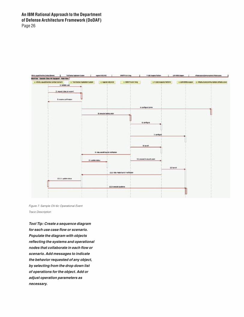
Figure 7. Sample OV-6c Operational Event
Trace Description
Tool Tip: Create a sequence diagram
for each use case flow or scenario.
Populate the diagram with objects
reflecting the systems and operational
nodes that collaborate in each flow or
scenario. Add messages to indicate
the behavior requested of any object,
by selecting from the drop down list
of operations for the object. Add or
adjust operation parameters as
necessary.
An IBM Rational Approach to the Department of Defense Architecture Framework (DoDAF)Page 27
Checkpoints for OV-6c
® Is there a sequence captured in a diagram for each use case flow or scenario identified for the subject system in the context of the operational enterprise?
® Have messages been characterized for each interaction in the flow of events being modeled?
® Do the messages and interactions reflect only external behavior (e.g., interactions between the subject system and other systems in the operational enterprise)?
® Do Operational Nodes have operations corresponding to each message called for in the sequence diagram?
® Has each message in a sequence diagram been selected from the drop down menu reflecting operations of the associated Operational Nodes?
® Is there a parameter for each operation in which information is transferred by way of a message?
® Is there an IO Entity data type associated with each parameter?
OV-7 Logical Data Model
The OV-7 reflects the structure and flow of key information being used to
achieve the functionality expressed in the Enterprise Use Cases. The content
of this product is should be directly attributable to the IO Entities identified
during construction of the OV-6c.
Checkpoints for OV-7
® Are all IO Entities represented in the OV-7 Logical Data Diagram?
® Have associations been added to show relationships between IO Entities?
® Have attribute values been provided for each parameter to meet the needs specified by the OV-3?
Tool Tip: Create a class diagram in
the OV-7 package by selecting the
package with the right mouse button
and clicking on Add Diagram > Class
Diagram. Add all of the identified IO
Entity classes by dragging them from
the Model Explorer to the diagram.
Add association relationships
as necessary.
An IBM Rational Approach to the Department of Defense Architecture Framework (DoDAF)Page 28
Systems View Products
Internally visible structure and behavior related to the realization by system and system nodesThe systems that comprise the operational architecture must collaborate
to implement the mission capability specified in the operational view. The
purpose of the Systems View is to provide multiple perspectives of the system
under consideration, and describe how the system(s) interact with other
elements of the enterprise architecture.
We start with a white box expansion of the subject system architecture by
identifying the logical and physical components of the system that must
interact in order to achieve the desired behavior. These systems (logical) and
system nodes (physical) are stereotyped classes, and are represented in a
System Context Diagram. Relationships between these elements are indica-
tive of operations/request messages that are specified when creating the
SV-10c. Other view products are used to provide further information related
to the physical and logical system interfaces, the system interactions, and
the planned evolution of the of the system in the context of the operational
enterprise.

An IBM Rational Approach to the Department of Defense Architecture Framework (DoDAF)Page 29
Product Title Description Representation Creation Order
SV-1
System Interface Description
Identifies systems and system components and their interfaces, within and between nodes. Models reconciliation of both logical and physical perspectives through realization of common interfaces.
Class diagram with classes, localities, and interfaces
3
SV-2Systems Communications Description
Models physical nodes and their related communications infrastructure
Composite Structure DiagramDeployment Diagram
6
SV-3Systems Matrix Models relationships between systems &
subsystems in the context of the overall architecture of the enterprise.
Model resident text matrix Exportable to XML
5
SV-4Systems Functionality Description
Identifies system behavior and the information flow related to that behavior.
Activity Diagram for each system use case
8
SV-5Operational Activity to System Function Traceability Matrix
Maps system internal behavior (realizations) to operational external activities (specification).
Model resident text matrix Exportable to XML
9
SV-6System Information Exchange Matrix
Details information exchanges between system elements (including applications and hardware allocated to those elements).
Model resident text matrix Exportable to XML
10
SV-7System Performance Parameters Matrix
Describes performance characteristics of system elements.
Model resident text matrix Exportable to XML Joint Realization Table(s)
11
SV-8System Evolution Description
Describes planned evolution increments toward a specific future implementation.
Schedule or project plan with timelines
12
SV-9System Technology Forecast
Describes emerging technologies that are likely to impact the current or specified future state of the system(s).
Text document 13
SV-10a
Systems Rules Model Describes constraints imposed on system functionality by business needs or operational mission requirements.
Architectural constraints that may or may not be incorporated in the model (OCL/SysML)Model referenced functional and non-functional requirements in text document
1
SV-10bSystems State Transition Description
Describes systems response to events. State Transition Diagram(s) ##
SV-10c
Systems Event/Trace Description
Describes internal systems behavior in terms of operational sequences and actions that realize operational scenarios or critical activities that reflect behavior identified in OV-6c..
Sequence Diagrams for both logical and physical realizations of behavior
2 – logical4 - physical
SV-11Physical Data Model IDescribes physical implementation of data storage
and movement.Class Diagram indicating schema relationships to the logical data elements in OV-7
7
## State Transition Diagrams are optionally used to model critical real-time responses to complex events requiring special treatment.

An IBM Rational Approach to the Department of Defense Architecture Framework (DoDAF)Page 30
SV-1 System Interface Description
The SV-1 creates the foundation for the subject system’s internal architecture. It
depicts systems, system nodes, and the interfaces that exist within and between
them. The SV-1 provides the linkage between the Operational View and the
Systems View. This means dealing with both the logical decomposition of the
system and the allocation of logical functionality to physical components. The
classifiers in this view represent objects in both logical and physical versions
of sequence diagrams for each system use case flow or scenario (derived from
operations/messages to the subject system) identified in the Operational View.
We start with identifying candidate logical elements comprising the subject
system. The initial discovery process may be intuitive and based on domain
experience. The focus, at this point, is to start thinking about the components
likely to comprise the logical subsystems. These may eventually turn out to be
subsystems, or even primitives, but that distinction is not important at this time.
Later, as a result of use-case flowdown and joint realization activities, we identify
remaining localities (as well as additional logical elements as we discover a need)
to which we allocate logical functionality in order to realize specified behavior.
From that information we can allocate operations indicated on sequence
diagrams to interfaces, each of which is realized by both logical (class) and
physical (locality) elements. The SV-1 diagram contains the classes, localities,
interfaces, and connections between those systems and systems nodes.
® Are all the systems (logical elements) that interact with the subject system included in the diagram(s)?
® Are all the systems nodes (physical elements/localities that interact with the subject system node included in the diagram(s)?
® Are all the significant subsystems (belonging to the subject system) and their internal and external interactions represented?
® Is there at least one interface class for each system-system node “pair”?
® For each system-system node pair, have the operations been “moved” or allocated to the corresponding interface class?
® For each system-system node pair, have appropriate <implement> relationships been drawn to the applicable interface class?
Tool Tip: Add the following UML
packages to the IBM Rational Eclipse-
based model under the System Nodes
package.
• Systems (logical subsystems)
• System Nodes (localities-physical)
• Interfaces
Tool Tip: Create a new class diagram,
named System Context, and add the
following UML elements:
• System (logical) candidates
• System Nodes (localities-physical)
candidates
• Interfaces
• Implements Relationships – later,
from information revealed in SV-10c
• Associations
An IBM Rational Approach to the Department of Defense Architecture Framework (DoDAF)Page 31
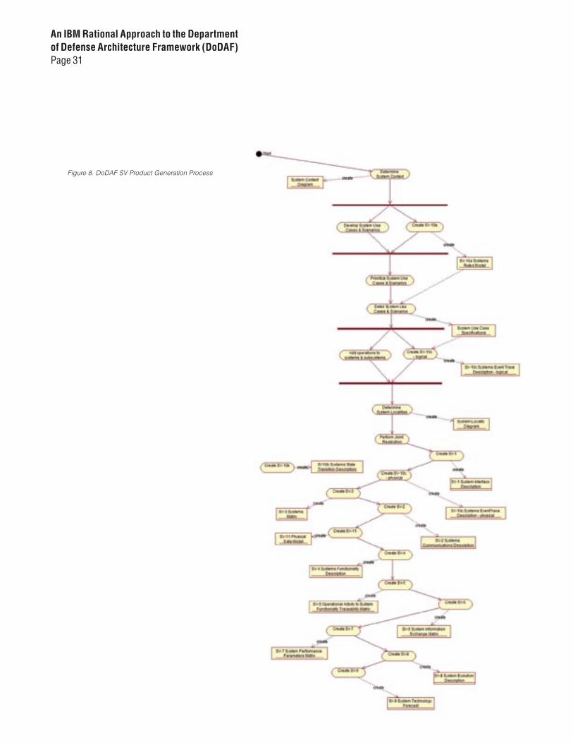
Figure 8. DoDAF SV Product Generation Process
An IBM Rational Approach to the Department of Defense Architecture Framework (DoDAF)Page 32
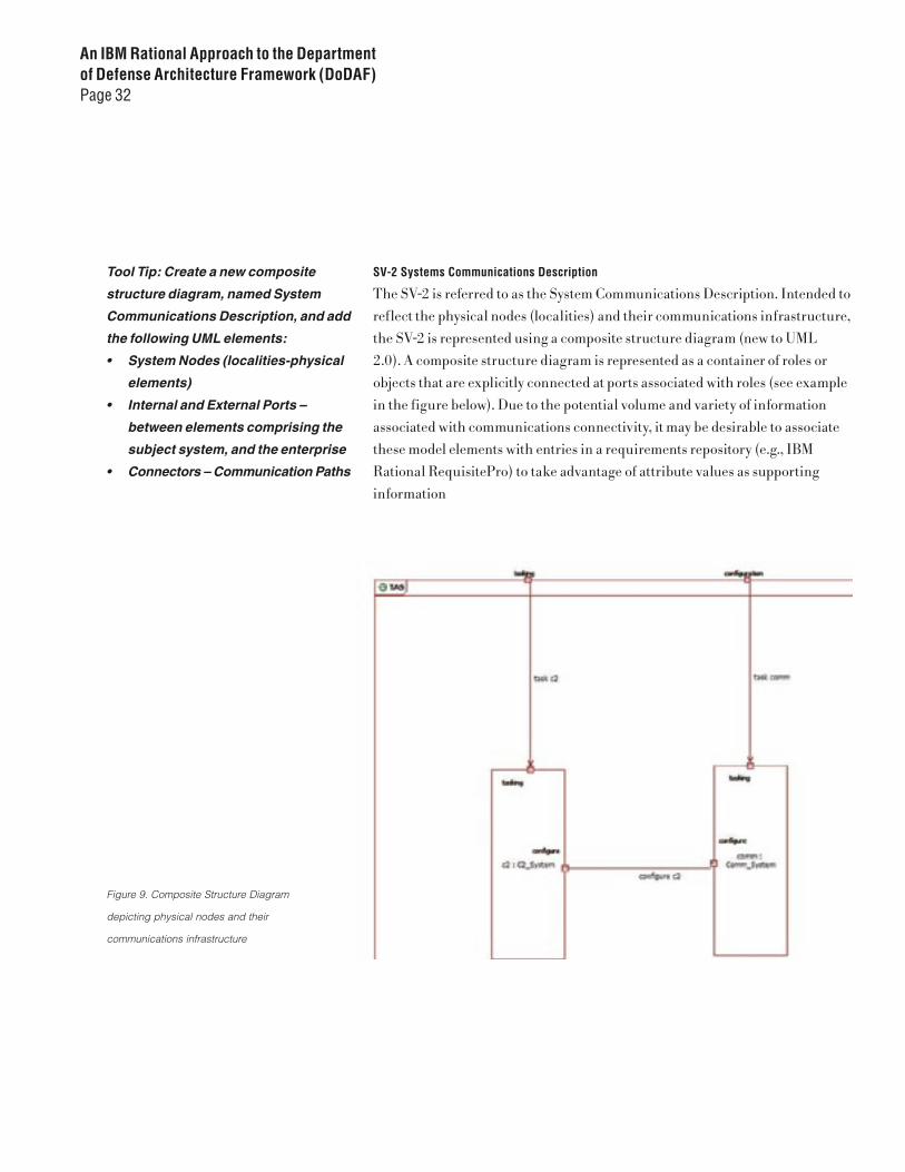
SV-2 Systems Communications Description
The SV-2 is referred to as the System Communications Description. Intended to
reflect the physical nodes (localities) and their communications infrastructure,
the SV-2 is represented using a composite structure diagram (new to UML
2.0). A composite structure diagram is represented as a container of roles or
objects that are explicitly connected at ports associated with roles (see example
in the figure below). Due to the potential volume and variety of information
associated with communications connectivity, it may be desirable to associate
these model elements with entries in a requirements repository (e.g., IBM
Rational RequisitePro) to take advantage of attribute values as supporting
information
Figure 9. Composite Structure Diagram
depicting physical nodes and their
communications infrastructure
Tool Tip: Create a new composite
structure diagram, named System
Communications Description, and add
the following UML elements:
• System Nodes (localities-physical
elements)
• Internal and External Ports –
between elements comprising the
subject system, and the enterprise
• Connectors – Communication Paths

An IBM Rational Approach to the Department of Defense Architecture Framework (DoDAF)Page 33
® Have all system nodes (physical elements/localities) associated with the subject system been included in the diagram(s)?
® Are ports defined for each specified connection between system nodes?
® Are connectors defined for each communications path between ports?
SV-3 Systems Matrix
The SV-3 is a matrix view of the system-to-system relationships that exist at
any specified level of system decomposition. At a minimum, the matrix should
identify which systems have relationships with other systems. Additional
content regarding characteristics of those relationships may be included, as
necessary. The information content to create the SV-3 is derived from the
relationships established in the logical and physical realizations of behavior
present in the SV-10c sequence diagrams
® Are all systems/subsystems and system nodes associated with the subject system represented in the matrix?
® For any system-system interaction, is there an “X” where the column and row intersect?
® Is this information consistent with the SV-10c?
SV-4 Systems Functionality Description
The SV-4 describes the functionality and required data flows necessary to
support required system behavior. We use an activity diagram with partitions
allocated to system elements responsible for activities. Object flows are added
to the activity flow in order to indicate data object inputs and outputs necessary
to specified activities. The SV-4’s information content provides an alternate
perspective from the information of the SV-10c sequence diagrams with their
messages and parameters.
® Is there an activity diagram for each identified use case, use case flow, and scenario?
® Does each activity diagram address all flows and/or scenarios associated with the applicable use case, use case flow, or scenario?
® Have significant Data Objects been incorporated in the activity diagrams to denote information inputs and outputs associated with the activity?
® Have partitions been added to the activity diagrams reflecting systems, subsystems, and system nodes performing activities?
® Have all activities been allocated to applicable partitions?
Tool Tip: Select the SV-3 package in
the IBM Rational Eclipse-based
modeling tool browser. Click the right
mouse button, and select DoDAF >
Show SV-3 View. A matrix of systems
will be displayed under the SV-3 tab, in
the lower right portion of the screen.
You have the option of clicking in that
matrix with the right mouse button,
and selecting Export, which results
in generation of an XML version
of the matrix.
Tool Tip: Create an activity diagram
for each system scenario or use case.
Create activities for each major step of
the flow or scenario, indicating logical
choices or decision points. Add the
following:
• Initial, Final, and Intermediate
Activities
• Decision Points, Guards, and other
clarifications
• Forks, Joins, and required
Control Flows
• Partitions for systems/subsystems
• The Objects, Object Flows and Data
Store elements that act as inputs/
outputs for identified activities
SV-5 Operational Activity to System Function Traceability Matrix
The SV-5 provides traceability between operational activities (e.g., use case
flow, scenarios) and the system functionality (operations) that realize the
required behavior. We produce this information in the form of a hierarchical
listing of the operational nodes, the operations they must support, and
realizations of those operations. Ideally, these would be extended to encompass
those systems/subsystems that collaborate to affect the realization, as well as
inclusion of the messages/operations sent to those system/subsystems
® Are the systems and all externally visible operations associated with those systems represented in the hierarchy?
® Are operations associated with the correct system, subsystem, or system node?
SV-6 System Information Exchange Matrix
The SV-6 is a matrix of Data Exchanges (similar to the OV-3) that represent the
behavior-based interactions between component systems and subsystems of the
subject system. The SV-6 is generated automatically using the IBM Rational
Eclipse-based modeling tool (by sourcing the SV-10c content). Each matrix row
represents a data exchange, which is comprised of characteristics of the data
transferred between roles/objects in an interaction from the SV-10c sequence
diagrams. The matrix identifies a distinct data exchange for each pair of
objects or roles that interact and exchange information. Specific data exchange
characteristics are typically associated with non-functional requirements
or design constraints. The content of each Data Exchange is representative
of an instantiation of a data object, where the attributes represent the data
characteristics required by the DoDAF.
Tool Tip: Select the SV-5 package in
the IBM Rational Eclipse-based
modeler browser. Click the right
mouse button, and select DoDAF >
Show SV-5 View. A hierarchy of
operational nodes, system/
subsystems and system nodes, and
their operations and realizations will
be displayed under the SV-5 tab, in the
lower right portion of the screen. You
have the option of clicking in that
display with the right mouse button,
and selecting Export, which generates
an XML version of the matrix. Note that
the SV-5 will show the traceability from
the operational nodes’ operations and
the system operations only if the
Operation Realization has been
invoked on each operational node.
This action creates a collaboration in
the SV-10c package that corresponds
to operational node, and populates
that collaboration with an interaction
(sequence diagram) for that specified
operational node’s operation. These
sequence diagrams should then be
populated per the recommendations
in the SV-10c section.

The SV-6 emphasizes the logical and operational characteristics of the
information exchanged. The product is not intended to provide exhaustive
capture of all details of information exchanged within the architecture, but as
a mechanism understand the most important aspects of significant exchanges.
An example of the information content from the DoDAF specification is
provided below. This content would typically trace to supplemental or non-
functional requirements.
Interface Identifier Data ExchangeIdentifier
Data Descriptionn Producer Consumer Nature of Transaction
System Interface Name and Identifier
System Data Exchange Name and Identifier
• Data Element Name and Identifier• Content• Format Type• Media Type• Accuracy• Units of Measurement• Data Standard
• Sending System Name and Identifier• Sending System Function Name and Identifier
• Receiving System Name and Identifier• Receiving System Function Name and Identifier
• Transaction Type• Triggering Event• Interoperability Level Achieved• Criticality
Interface Identifierr Data ExchangeIdentifier
Performance Attributes Information Assurance Security
System Interface Name and Identifier
System Data Exchange Name and Identifier
• Periodicity• Timeliness• Throughput• Size
• Access Control• Availability• Confidentiality• Dissemination Control• Integrity• Non-Repudiation Consumer
• Protection (Type Name, Duration, Date)• Classification• Classification Caveat• Releasability• Security Standard
Department of Defense Architecture Framework
Working Group, “DoD Architectural Framework”,
Version 1.0, Volume II, August 2003

An IBM Rational Approach to the Department of Defense Architecture Framework (DoDAF)Page 36
Checkpoints for SV-6
® Have data objects been identified for each parameter specified in each inter-object message in SV-10c sequence diagrams?
® Have attributes been established for each Data Object class , consistent with the guidance provided in Volume II of the DoDAF specification?
® Is there an entry for each message of sequence diagram indicating information passed as parameters?
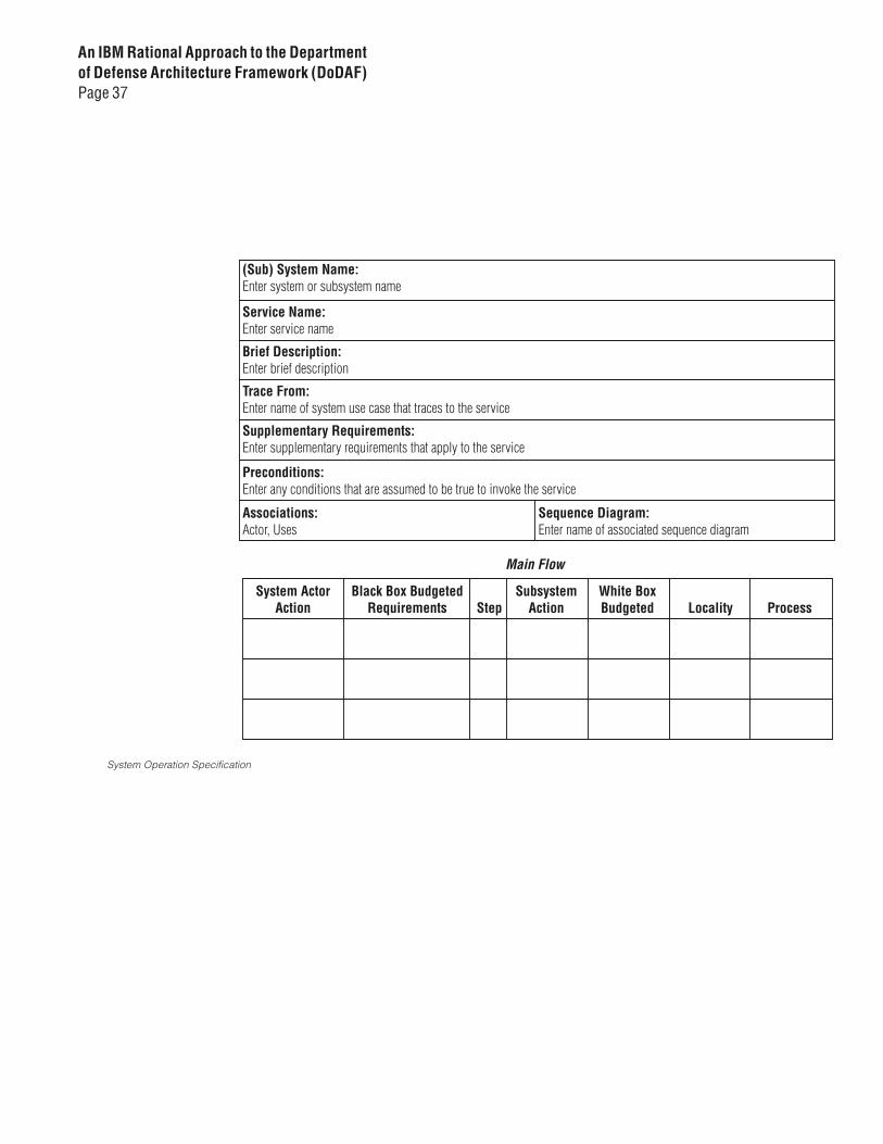
SV-7 System Performance Parameters Matrix
The SV-7 describes characteristics considered critical to effectively attaining
mission objectives assigned to the subject system. This information can best be
presented as a form, table, or matrix. The application domain determines the
specific content of this view. A notional example is available for reference in
the DoDAF specification. A Joint Realization Form (called a System Operation
Specification), specifically designed for this purpose, is also available through
IBM Rational Services. When completed, we store the SV-7 in the Documents
folder associated with the model or as a traceable requirements document
under IBM Rational RequisitePro.
® Has a Joint Realization been prepared for each specified operation in the SV-10c?
® Is the information in the Joint Realization allocated to appropriate attributes of the respective data exchanges and documented in the model or associated documentation?
® Has traceability been established between model elements and the applicable set of SV-7 characteristics?
Tool Tip: Select the SV-6 package in
the IBM Rational Eclipse-based
modeler browser. Click the Right
mouse button, and select DoDAF >
Show SV-6 View. A matrix of IERs will
be displayed under the SV-6 tab, in the
lower right portion of the screen. You
have the option of clicking in that
matrix with the right mouse button,
and selecting Export, which generates
an XML version of the matrix
Tool Tip: Open a document using the
System Operation Specification
Template. Capture the significant
performance characteristics of the
operation as the realization is
incrementally elaborated. Store the
content in Requisite Pro
An IBM Rational Approach to the Department of Defense Architecture Framework (DoDAF)Page 37
System Operation Specification
An IBM Rational Approach to the Department of Defense Architecture Framework (DoDAF)Page 38
SV-8 System Evolution Description
The SV-8 is a plan/schedule for the system’s evolution, in the context of
the evolving enterprise. The SV-8 is typically captured in a scheduling tool
(e.g., Microsoft Project). Key milestones are associated with incremental
implementations of changes to the structure and/or behavior of the system.
We recommend storing the file associated with the schedule in the Documents
folder associated with the the architectural model.
® Have architectural increments been defined and associated with milestones identified in the plan or schedule?
® Have dependencies between enterprise system components been identified and addressed by the plan or schedule?
SV-9 System Technology Forecast
The SV-9 identifies emerging technology that is likely to impact the structure
or behavior of the system in its enterprise context. Ideally, incremental changes
in technology are correlated with the milestones in the SV-8 to facilitate overall
decision–making and enterprise management. We recommend storing the
file associated with the schedule in the Documents folder associated with the
architectural model.
® Are all pertinent technologies and standards related to the architectural evolution in OV-8 documented?
® Are the appropriate attributes for evolving technologies and standards documented in the model?
Tool Tip: Create a schedule using an
appropriate planning tool. Identify key
milestones associated with specified
evolutionary points for the system in
its enterprise context. Add other
applicable planning factors as
necessary.
Tool Tip: There is no specified format
for this product. One option would be
to use a similar planning tool to that for
the SV-8. We chose to create a
document with entries for each
technology, captured as a requirement
in IBM Rational RequisitePro, and then
assign attributes for the relevant
characteristics of that technology.
Next step is to create a trace
relationship from the system element
impacted to the specified requirement.

An IBM Rational Approach to the Department of Defense Architecture Framework (DoDAF)Page 39
SV-10a Systems Rules Model
The SV-10a captures constraints restricting behavior of the systems/
subsystems involved in satisfying operational objectives. Information is
captured in text and produced in document form. A template would typically
be provided and tailored to the organizational audience. The distinction
between business rules/constraints and requirements can be challenging. The
guidance here is that decision points in the activity diagrams should reflect
the instantiation of those rules. Some of this content may lend itself to being
expressed using SysML or Object Constraint Language (OCL) and used to
validate architectural artifacts under the modeling tool. The primary product
for this view is a document. The SV-10a is analogous to the OV-6a, but at a lower
level of systems decomposition. As with the OV-6a we recommend using
a document and an associated requirements management tools like IBM
Rational RequisitePro.
Checkpoints for SV-10a
® Is there sufficient information in the rules to deterministically explain the logical branching indicated in each activity diagram shown in SV-4?
® Are the rules clear, deterministic and unambiguous?
SV-10b Systems State Transition Description
When the behavior of one or more key architectural elements is event-driven,
modeling with State Diagrams can be especially useful in understanding that
behavior. Where this approach is warranted, the SV-10b is produced.
Checkpoints for SV-10b
® Does the state diagram account for all behavior of the objects being considered?
® Are all impacting events accounted for?
® Are all actions and associated transitions accounted for?
® Are all resulting states accounted for?
Tool Tip: Select the SV-10b package in
the IBM Rational Eclipse-based
modeler browser. Click the Right
mouse button, and select DoDAF >
Create SV-10b. This will open a
Microsoft Word template based on the
content specified in Volume I of the
DoDAF specification. Save the
document to a convenient location in
the files system. Once the file has been
saved (and closed) Select File > Import
> File System and navigate to the
document location. Select the
document and choose the model
Documents package at the overall
model level.
Tool Tip: Create State Machine
diagrams for each system, subsystem,
or system node whose behavior is
event-driven and sufficiently complex
to warrant state-based analysis. Create
states representing the behavioral
results of responses to events. Add
events, actions, and state transitions
as required.
An IBM Rational Approach to the Department of Defense Architecture Framework (DoDAF)Page 40
SV-10c Systems Event/Trace Description
The SV-10c describes internal behavior of the subject system for each operation
identified in the OV6c. We use sequence diagrams that focus on systems/
subsystems and system nodes that interact using messages. These messages
represent requests of a system/subsystem/system node by associated systems,
subsystems or system nodes. The operation specification exists at the level of
the Operational View, and is realized in the Systems View. The structure for the
realization is created by selecting the class owning the operation and click on
the right mouse button, then selecting DoDAF > Create Operation Realizations.
Any information exchanged as part of those requests (e.g., parameters), is
represented by instances of an IO Entity class. Each message interaction also
represents a data exchange, and is used to populate the SV-6 matrix. We create
this content by selecting DoDAF > Create SV-6. The matrix is displayed in
the SV-6 tab.
Checkpoints for SV-10c
® Is there a sequence captured in a diagram for each use case flow or scenario identified for the subject system in the context of the operational enterprise?
® Have messages been characterized for each interaction in the flow of events being modeled?
® Do the messages and interactions reflect only external behavior (e.g., interactions between the subject system and other systems in the operational enterprise)?
® Do Operational Nodes have operations corresponding to each message called for in the sequence diagram?
® Has each message in a sequence diagram been selected from the drop down menu reflecting operations of the associated Operational Nodes?
® Is there a parameter for each operation in which information is transferred by way of a message?
® Is there an Data Object class associated with each parameter?
Tool Tip: For each operation to be
realized, select the class owning the
operation and click on the right mouse
button, select DoDAF > Create
Operation Realizations. Navigate
in the Model Explorer to the
For each operational realization
that has been created, rename it
appropriately. Populate the diagram
with objects reflecting the systems
and operational nodes that collaborate
in each flow or scenario. Add
messages to indicate the behavior
requested of any object, by selecting
from the drop-down list of operations
for the object. Add or adjust operation
parameters as necessary.

An IBM Rational Approach to the Department of Defense Architecture Framework (DoDAF)Page 41
SV-11 Physical Data Model
The SV-11 is the complement to the OV-7. We use a class diagram to represent
database schema relationships necessary to host the informational content
represented by the OV-7 Logical Data Model and the Data Objects of the SV-4.
® Are all schemas, database instances, tablespaces, and databases represented on the diagram(s)?
® Are all the relationships between the above elements modeled on the diagram(s)?
® Is the physical organization of the data consistent with the Logical Data Model in OV-7?
Technical Standards View
Standards and constraints that impact the subject system in the context of the operational enterprise.
The Technical Standards View provides the guidance that directs or constrains
the implementation of the systems described in the Systems View. The TV
reflects standards and limiting factors upon which design decisions are made
while incrementally developing the system(s) to meet the mission objectives
specified in the Operational View. The TV reflects address standards applicable
to the current architecture (TV-1) and the evolution of that architecture (TV-2).
Tool Tip: Create a class diagram in
the SV-11 package, and then
• Populate it with existing IO Entities
and Data Objects
• Add classes stereotyped as
<schema>, <instance>,
<tablespace>, <database>,
as necessary
• Add associations, aggregations,
composition, as necessary
Product Title Description Representation Creation Order
TV-1
Technical Architecture Profile TExtraction of standards that apply to the specified architecturee
Model referenced standards and constraints in text document. Consider use of RequisitePro or equivalent requirements tool.
1
TV-2
Standards Technology Forecast Description of emerging standards that are expected to apply to the architecture, in specified timeframes
Model referenced standards and constraints (with time/milestone criteria) in text document. Consider use of RequisitePro or equivalent requirements tool.L
2
An IBM Rational Approach to the Department of Defense Architecture Framework (DoDAF)Page 42
TV-1 Technical Architecture Profile
The TV-1 describes of existing standards and operational constraints that will
likely impact the operational enterprise. The DoDAF specification provides
a sample template suggesting that this information would be best captured
using a text-based document. We recommend incorporating relationships
between specific standards and the architectural elements impacted by using
of a requirements management tools like RequisitePro. We can store specific
characteristics of the standard as attributes of the standard, so that establishing
traceability becomes a relatively simple process.
® Have all significant standards been captured that are associated with the system in the enterprise context?
® Have necessary characteristics of each standard been established and values assigned for each standard?
® Has traceability been established between each standard and the architectural affected element?
TV-2 Standards Technology Forecast
The TV-2 describes of potential and emerging standards and operational
constraints that may impact the operational enterprise and its architecture as
it, and its component systems evolve. There are two categories of information
captured in this product: (1) expected changes to standards or constraints
referenced in the TV-1, and (2) changes to standards or new standards
associated with evolution of the enterprise to accommodate new systems and
capabilities. The approach to capturing this information is the same as with the
TV-1, except that traceability is also necessary to the SV-8 and SV-9 for entries
that fall into category (2) above.
® Have all the standards and constraints in TV-1 been reviewed for possible evolution and new associated standards?
® Where evolution is anticipated, has a TV-2 entry, with applicable attribute values, been established?
® Has appropriate traceability to TV-1, SV-8, and SV-9 been established?
Tool Tip: Create a Microsoft Word
template tailored to the architectural
characteristics of the system, the
operational guidance, regulatory
requirements, and technical direction
driving the development of the system.
Refer to the suggested template for the
TV-1 in Volume II of the DoDAF
specification. Create a requirement
type and applicable attributes in an
associated IBM Rational RequisitePro
project. Add a record for each standard,
setting attribute values. Establish
traceability from each standard to any
architectural element(s) affected.
An IBM Rational Approach to the Department of Defense Architecture Framework (DoDAF)Page 43
Conclusion
IBM Rational’s approach to DoDAF incorporates a proven process for systems
engineering with a powerful, integrated tool suite. We leverage the content
of DoDAF products as enterprise architecture is incrementally elaborated
from abstract capabilities to concrete logical and physical representations.
A robust, scaleable process, coupled with automation, drives development
of consistent architectural content in a centralized model repository. This
provides necessary enablement for the larger development organization and key
decision-makers of the operational enterprise.
Tool Tip: Create a Microsoft Word
template tailored to the architectural
characteristics of the system, the
operational guidance, regulatory
requirements, and technical direction
driving the development of the system.
Refer to the suggested template for
the TV-1 in Volume II of the DoDAF
specification. Create a requirement
type and applicable attributes in an
associated RequisitePro project.
• Add a record for each standard,
setting attribute values
• Establish traceability from each
standard to any architectural
element(s) affected
• Establish traceability to affected
SV-8 and SV-9 entries
An IBM Rational Approach to the Department of Defense Architecture Framework (DoDAF)Page 44
© Copyright IBM Corporation 2006
IBM Corporation Software Group Route 100 Somers, NY 10589 U.S.A.
Produced in the United States of America 01-06 All Rights Reserved
IBM, the IBM logo, the On Demand Business logo and Rational are trademarks of International Business Machines Corporation in the United States, other countries or both.
Microsoft and Windows are trademarks of Microsoft Corporation in the United States, other countries or both.
Other company, product and service names may be trademarks or service marks of others.
The information contained in this documentation is provided for informational purposes only. While efforts were made to verify the completeness and accuracy of the information contained in this documentation, it is provided “as is” without warranty of any kind, express or implied. In addition, this information is based on IBM’s current product plans and strategy, which are subject to change by IBM without notice. IBM shall not be responsible for any damages arising out of the use of, or otherwise related to, this documentation or any other documentation.
Nothing contained in this documentation is intended to, nor shall have the effect of, creating any warranties or representations from IBM (or its suppliers or licensors), or altering the terms and conditions of the applicable license agreement governing the use of IBM software.
References in this publication to IBM products or services do not imply that IBM intends to make them available in all countries in which IBM operates.
All statements regarding IBM future direction or intent are subject to change or withdrawal without notice and represent goals and objectives only. ALL INFORMATION IS PROVIDED ON AN “AS-IS” BASIS, WITHOUT ANY WARRANTY OF ANY KIND.
The IBM home page on the Internet can be found at ibm.com
Produced in the US.
G507-1903-00
References1 Department of Defense Architecture Framework Working Group,
“DoD Architectural Framework”, Version 1.0, Volume I, August 2003
2 Department of Defense Architecture Framework Working Group, “DoD Architectural Framework”, Version 1.0, Volume II, August 2003
3 James Rumbaugh, Ivar Jacobson, Grady Booch, “The Unified Modeling Language Reference Manual, Second Edition” Addison-Wesley, 2005
4 Murray Cantor, “RUP SE: The Rational Unified Process for Systems Engineering” The Rational Edge, August 2003
5 Murray Cantor, “The Rational Unified Process for Systems Engineering Part I: Introducing RUP SE 2.0” The Rational Edge, August 2003
6 Murray Cantor, “The Rational Unified Process for Systems Engineering Part II: System Architecture” The Rational Edge, September 2003
7 Murray Cantor, “The Six Principles of Systems Development” 2004
8 Philippe Kruchten, “The Rational Unified Process - An Introduction”, 3rd ed., Addison-Wesley, 2004
9 LtGen James F. Cartwright, “Changing the Mindset, Innovation and Changing the Military Culture Seminar”. www.oft.osd.mil/library/library_files/briefing_86
Related Documents