International Journal of Advanced Technology and Engineering Exploration, Vol 5(45) ISSN (Print): 2394-5443 ISSN (Online): 2394-7454 http://dx.doi.org/10.19101/IJATEE.2018.545012 232 An experimental study on the behaviour of GFRP pultruded I beam reinforced with CFRP laminates G.Ganesan 1* and G.Kumaran 2 Research Scholar, Department of Civil and Structural Engineering, Annamalai University, Annamalai Nagar, Tamil Nadu, India 1 Professor, Department of Civil and Structural Engineering, Annamalai University, Annamalai Nagar, Tamil Nadu, India 2 ©2018 ACCENTS 1.Introduction In the construction industry, due to the advantages like light weight, high power, resistance to decay etc., usage of fibre-reinforced polymers (FRP) pultruded profiles have gained a wide application. Recently, they are widely being used in the construction of bridge systems, walkways and other structures which are brought into light to corrosive environment. The procedure of unidirectional filaments along with other fabric mats impregnating in resin is known as pultrusion which is basically a manufacturing process. This is later pulled through a heated die to produce long prismatic components with a constant cross-section. The thick structural component with a small number of reinforcement layers are pultruded composite plates and beams. GFRP profiles are commonly used in construction due to the low cost of glass fibres. Since GFRP profiles have relatively low elastic moduli, it is often administered by limitations in change at service load levels or by bucking, in case of thin-walled sections, instead of ultimate strength limits. *Author for correspondence Despite their many advantages, the model of GFRP pultruded profiles is governed by deformation in service limit states and by local and global buckling in ultimate limit states. To overcome these limitations, GFRP profiles are reinforced with CFRP laminates of different layup sequence. For the design of composite structures made of pultruded profiles, Davalos and Qiao [1] explained that both rigidity and strength are equally significant and depend on the material and on the element cross- section. The laminate of different fibre orientation of advanced composite materials may display complex anisotropic behaviour. The section walls of profiles fabricated by pultrusion process feasibly simulated as laminated composites with comparable orthotropic mechanical properties in their longitudinal and transverse directions. While changes in the profile section geometry are easily related to changes in the stiffness, changes in the material and fibre orientation are not so obvious to be evaluated. Bank [2] show that, the longitudinal elastic modulus obtained from a flexural test on a FRP pultruded profile is dissimilar from the one Research Article Abstract Glass fibre reinforced polymers (GFRP) pultruded profiles are being widely used as a structural material in the construction industry, particularly in a corrosive environment as an alternative material for steel. Despite its many advantages, their design is limited by deformation in service limit states and by local and global buckling in ultimate limit states. To overcome these limitations, they can be reinforced with carbon fiber reinforced polymer (CFRP) laminates. In this exploration, the structural behaviour of GFRP pultruded profiles reinforced with CFRP laminates on the flanges has been observed. The mechanical properties are obtained from the specimen extracted from the flanges. Tests of three-point and four-points twisting have been conducted with different layup sequence of CFRP laminates, on full-scale models. A comparative study is made with experimental and analytical results. Keywords Glass fibre reinforced plastic, Pultruded profiles, Flexural stiffness, Local buckling.

Welcome message from author
This document is posted to help you gain knowledge. Please leave a comment to let me know what you think about it! Share it to your friends and learn new things together.
Transcript

International Journal of Advanced Technology and Engineering Exploration, Vol 5(45)
ISSN (Print): 2394-5443 ISSN (Online): 2394-7454
http://dx.doi.org/10.19101/IJATEE.2018.545012
232
An experimental study on the behaviour of GFRP pultruded I beam
reinforced with CFRP laminates
G.Ganesan1*
and G.Kumaran2
Research Scholar, Department of Civil and Structural Engineering, Annamalai University, Annamalai Nagar, Tamil
Nadu, India1
Professor, Department of Civil and Structural Engineering, Annamalai University, Annamalai Nagar, Tamil Nadu,
India2
©2018 ACCENTS
1.Introduction In the construction industry, due to the advantages
like light weight, high power, resistance to decay etc.,
usage of fibre-reinforced polymers (FRP) pultruded
profiles have gained a wide application. Recently,
they are widely being used in the construction of
bridge systems, walkways and other structures which
are brought into light to corrosive environment.
The procedure of unidirectional filaments along with
other fabric mats impregnating in resin is known as
pultrusion which is basically a manufacturing
process. This is later pulled through a heated die to
produce long prismatic components with a constant
cross-section. The thick structural component with a
small number of reinforcement layers are pultruded
composite plates and beams.
GFRP profiles are commonly used in construction
due to the low cost of glass fibres. Since GFRP
profiles have relatively low elastic moduli, it is often
administered by limitations in change at service load
levels or by bucking, in case of thin-walled sections,
instead of ultimate strength limits.
*Author for correspondence
Despite their many advantages, the model of GFRP
pultruded profiles is governed by deformation in
service limit states and by local and global buckling
in ultimate limit states. To overcome these
limitations, GFRP profiles are reinforced with CFRP
laminates of different layup sequence.
For the design of composite structures made of
pultruded profiles, Davalos and Qiao [1] explained
that both rigidity and strength are equally significant
and depend on the material and on the element cross-
section.
The laminate of different fibre orientation of
advanced composite materials may display complex
anisotropic behaviour. The section walls of profiles
fabricated by pultrusion process feasibly simulated as
laminated composites with comparable orthotropic
mechanical properties in their longitudinal and
transverse directions.
While changes in the profile section geometry are
easily related to changes in the stiffness, changes in
the material and fibre orientation are not so obvious
to be evaluated. Bank [2] show that, the longitudinal
elastic modulus obtained from a flexural test on a
FRP pultruded profile is dissimilar from the one
Research Article
Abstract Glass fibre reinforced polymers (GFRP) pultruded profiles are being widely used as a structural material in the
construction industry, particularly in a corrosive environment as an alternative material for steel. Despite its many
advantages, their design is limited by deformation in service limit states and by local and global buckling in ultimate limit
states. To overcome these limitations, they can be reinforced with carbon fiber reinforced polymer (CFRP) laminates. In
this exploration, the structural behaviour of GFRP pultruded profiles reinforced with CFRP laminates on the flanges has
been observed. The mechanical properties are obtained from the specimen extracted from the flanges. Tests of three-point
and four-points twisting have been conducted with different layup sequence of CFRP laminates, on full-scale models. A
comparative study is made with experimental and analytical results.
Keywords Glass fibre reinforced plastic, Pultruded profiles, Flexural stiffness, Local buckling.
International Journal of Advanced Technology and Engineering Exploration, Vol 5(45)
233
achieved from a flexural test on a solid bar coupon
extracted from the same profile. This happens due to
the difference in mechanical properties between a full
size profile of thin walled section and a solid bar of
rectangular section. But, Meier et al. [3] stated that
reliable values of elastic moduli for FRP beams can
be got by conducting tests on small coupons which
have been extracted from pultruded profiles. Due to
this deviation on research findings, Kumar et al. [4],
suggested to conduct more experimental tests and
researches about the behaviour of full-size pultruded
beams and also of coupons which has been extracted
from these beams.
The aim of this study is to figure out the behaviour of
GFRP pultruded beams through experiment and
analysis. In the experimental programme, two sets of
beams of the equal cross section, i.e., 200 × 100 ×
8mm, reinforced with CFRP laminates of difference
layup sequence are considered.
2.Timoshenko beam theory A designer who requires obtaining suitable
mechanical properties for a selected theory, beam
theory can be used to analyse structural elements.
The degree of anisotropy of the composite material is
one of the factors which the choice of beam theory
depends on. The ratio of longitudinal-to-shear
modulus is higher than isotropic materials which are
displayed by composite materials. This ratio varies if
there is an increase in the anisotropy degree of the
material. For this reason shear deformation in the
beam will increase as the anisotropy degree of the
material increases.
To account for shear deformation, Timoshenko beam
theory (TBT) gives a better estimation of the actual
behaviour as contrast to the traditional Euler-beam
theory. In TBT, the plane sections of the beam are
assumed to remain plane, but no longer usual to the
beam neutral axis. The maximum deflection is given
by the expression.
4448
3
2/yGK
WL
yEI
WL
Lxcf
2/
121
48
3
rLyGK
E
yEl
WL (1)
Where W is the applied vertical load, distributed at
two different locations, L is the span or the distance
between the supports, A is the sectional area and I is
the moment of inertia of the section with respect to y
axis; E is the flexural elastic longitudinal modulus for
isotropic material; G is the shear modulus, and K is
the shear area coefficient. For beams made of
composite materials, equivalent longitudinal and
shear moduli, E and G are required in order to obtain
the beam maximum deflection by means of Equation
1. The shear deformation should also be considered
while calculating the deflection for a composite
material. According to Tamizhamuthu [5] changes in
the fibre orientation can increase the rigidity of the
profile. Ganesan [6] has conducted studies on FRP
frames which reveal that shear deformation plays a
vital role in calculating the deflection.
3.Classical laminate theory (CLT)
The in-plane stiffness properties may be calculated
using classical lamination theory, in which the
pultruded plate is characterized by its in-plane
extensional stiffness coefficients, . The in-plane
engineering stiffness properties may be obtained
from standard tests on coupons separated from the
pultruded profile. In this approach, the laminate is
considered to be homogeneous. Since the orthotropic
plates, in the pultruded profile, are assumed to be
homogeneous on a macro mechanics level, the plate
flexural properties can be calculated from their in-
plane extensional engineering properties (obtained
either from test data or from the in-plane extensional
matrix).The orthotropic plate flexural rigidities (the
equivalents of per unit width for a beam) are given
as:
( ) (2)
( ) (3)
( )
( ) (4)
(5)
Where, , , and are the longitudinal,
transverse, coupling, and shear flexural rigidities and
: is the plate thickness. The flexural rigidities relate
the plate bending moments (per unit length) to the
plate curvatures Timoshenko and Woinowsky-
Krieger [7]. This notation is often used in analytical
equations for pultruded profiles.
The in-plane strength properties may be obtained
from theoretical calculations or from testing of
coupons taken from the laminate, where the
theoretical predictions are used, the first ply failure
(FPF) is assumed to represent the strength of the

Ganesan and Kumaran
234
laminate. Coupon testing is recommended for
obtaining the strength properties for structural design.
3.1Flexural stiffness using CLT
The flexural and shear stiffnesses can be computed
based on the approximate classical laminate theory.
Pultruded beams, orthotropic in nature, are
approximated to be isotropic, in computing the
flexural and shear rigidity. The influence of
secondary directions is ignored. Nagaraj and
GangaRao [8] suggest that the approximation can be
used in rigidity computations.
Pultruded profiles are manufactured using fibre
bundles and fibre mats arranged in layered sequence.
Thus, a pultruded profile can be approximated to
consist of different layers of fibre laminates of
different thickness. A pultruded laminate consists of
three stiffness terms, viz., extensional stiffness (Ke),
bending stiffness (Kb), and bending-extension
coupling stiffness (Kbe). The bending-extension
coupling stiffness is zero for symmetric laminates.
The extensional stiffness (Ke) and bending stiffness
(Kb) terms for a beam’s flange and web are given by
Flange:
∑ ∑
[
]
(6)
Web:
∑
∑ (7)
Where b: flange width; d: web depth; Er: elastic
modulus of rth
layer in the structural coordinate
system; tr: thickness of rth
layer and Zr: distance of
the middle surfaces of rth
layer from the middle
surface of the laminate. Er represents the anisotropic
modulus. The approximation of a laminate to be
isotropic (i.e., E1=E2; µ12= µ 21; G12=G) eases the
computation of Er required in (5.54, 5.55) and
reduces the complexity of beam rigidity
computations. The influence of secondary directions
was not to be significant. Approximating the laminate
to be isotropic (E1=E2; µ12= µ21) reduces to the form
E=E1
The procedure of theoretical evaluation of flexural
stiffness can be explained as below:
Computation of elastic modulus of 900GSM Bi-axial
mat (+45/-45deg)
Thickness of laminate per layer: t; Weight of fibre
mat/sq.m: Wf; Density of glass fibre: ρfVolume of
glass fibre in Laminate: Fv=Wf/ρf; Volume of lamina:
Lv Volume fraction of fibres: Vf=Fv/Lv; Vm Volume
fraction of matrix Using the rule of mixtures the
elastic modulus in the direction of fibres
(8)
Using Mechanics of materials
E2 =( )
(9)
G12 =( )
(10)
or - deg., the mat is considered to be having
two laminates. The elastic modulus can be multiplied
by cos . imilarly, the same procedure can be for
calculating the properties of carbon mat of 300GSM
density with uni-directional mat. For bi-directional
mat, 50% of carbon fibre in zero deg. and 50% of
carbon fibre in 90°. Therefore, the elastic modulus
can be accounted for 150 GSM only.
The elastic modulus of glass rovings, the following
procedure can be allotted with the following
properties:
Length of fibre in m/kg ((1000/(tex/1000)); No. of
bundles for each roving layer (n);Width of lamina
(Wf); Thickness of each layer (t); Density of fibres
(ρf); Diameter of fibres Df =(√
);Volume of fibre
Vf=
Volume fraction of matric (Vm = 1 Vf)
Based on the above calculations, the elastic modulus
is calculated for bi-axial mat, carbon mat and glass
rovings as per the equation described in the
subsequent studies.
( ) (11)

International Journal of Advanced Technology and Engineering Exploration, Vol 5(45)
235
( ) (12)
Similarly, Shear rigidity N (kAG) can be calculated
as
( ) (13)
Based on the above calculations the following values
are for the six types of beams (Table 1).
Table 1 Theoretical computation of EI and kAG
Beam type EI(1011)
N.mm2
N (106)
IBBM3MR 6.227 4.039
IBOUCL3MR 7.204 4.039
IBOBCL3MR 6.716 4.039
IBOUOBCL3MR 7.693 4.039
IBTUOBCL3MR 8.67 4.039
IBOUTBCL3MR 8.181 4.039
l
l/3 l/3 l/3
P/2 P/2
x
x
L
T
L
T
Y X
Z
Figure 1 Local and global co-ordinates relationship
for a pultruded profile
Figure 1 shows the local and global co-ordinates
relationship for a pultruded profile.
4.Experimental investigations
4.1Preparation of GFRP I-beams along with
CFRP laminates with different fibres
orientations
All GFRP I-beams are manufactured using pultrusion
process as per the ASTM D 4385–2013 standards and
are designated as per the fibre orientations. Table 2
shows the designations of different beams. The
experiment was carried out on six sets of FRP
pultruded I Beams and all the beams of this category
are manufactured and tested for a span of 3000 mm.
Such beams are held on simple supports i.e. one end
has the roller support and the other end is hinged.
Along the span direction, at six locations with equal
intervals, the flanges of all the beams are restrained
laterally for all sets of beams. The first set consists
of two FRP pultruded I beams, of conventional type,
without any CFRP laminates. It is designated as
IBBM3MR.
The second set consists of two FRP pultruded I
beams, with one layer of bi-directional mat both in
the top and bottom flanges, and spanned over 3m
with the flanges which are restrained along the span.
The flanges and the interjection between the flanges
and web are reinforced with one layer of uni-
directional (0°) CFRP laminates of 300 GSM. It is
designated as IBOUCL3MR. The thickness of uni-
directional laminates come around 0.3 mm.
The third set consists of two FRP pultruded I beams,
with one layer of bi-directional mat all along the
outer surface and spanned over 3m with the flanges
which are restrained along the span. The flanges and
the interjection between flanges and web are
reinforced with one layer of bi-directional (0°/90°)
CFRP laminates of 300GSM. It is designated as
IBOBCL3MR. The thickness of the bi-directional
laminate is 0.3mm.
The fourth set consists of two FRP Pultruded I
beams, with one layer of bi-directional mat all along
the outer surface and spanned over 3m with the
flanges which are restrained along the span. The
flanges and the interjection between the flanges and
web are reinforced with one layer of uni-directional
and one layer of bi-directional CFRP laminates each
of 300 GSM. It is designated as IBOUOBCL3MR.
The overall thickness of both the laminate is 0.6mm.
The fifth set consists of two FRP Pultruded I beams,
with one layer of bi-directional mat all along the
outer surface and spanned over 3m with the flanges
which are restrained along the span. The flanges and
the interjection between the flanges and web are
reinforced with two layers of uni-directional and one
layer of bi-directional CFRP laminates each of
300GSM. It is designated as IBTUOBCL3MR. The
overall thickness of the laminate is 0.9mm.
The sixth set consists of two FRP Pultruded I beams,
with one layer of bi-directional mat all around the
outer surface and spanned over 3m with the flanges
which are restrained (FR) along the span. The flanges
and the interjection between the flanges and web are
reinforced with one layer of uni-directional and two
layers of bi-directional CFRP laminates. It is
designated as IBOUTBCL3MR. The overall
thickness of the laminate is 0.9mm.

Ganesan and Kumaran
236
Table 2 Beam with different designations for experimental analysis
Profile of specimen Type FR Span(mm) No.S
I-200 IBBM3MR R 3000 2
I-200 IBOUCL3MR R 3000 2
I-200 IBOBCL3MR R 3000 2
I-200 IBOUOBCL3MR R 3000 2
I-200 IBTUOBCL3MR R 3000 2
I-200 IBOUTBCL3MR R 3000 2
All the pultruded I-beams used in this study have a
uniform cross-section and a depth of 200mm. The
pultruded I beams are manufactured by pultrusion
process by Meena Fibreglas Industries, Pondicherry,
India. Each beam has ECR glass rovings of 4800 tex
(Owen Cornings India, Mumbai) with Isopthalic
grade polyester resin (Ashland India, Mumbai). On
the outer surface, bi-directional mat of 900 GSM with
- direction fibre is used ( eartex India,
umbai). curing temperature of c is
maintained during the production. The post curing is
done in a m long oven, at c for hours (even
though it is specified for profiles made using epoxy
resin) to ensure complete cross linking of polymeric
chain. Once it is post cured, all the specimens are fine
cut to a required length using a diamond coated
rotary blade. After the specimens are cut and they
are inspected, visually for any defects as per ASTM
D 4385 – 2013.
The beams with CFRP laminates require additional
surface preparation for applying CFRP laminate. The
surface over which the carbon fibre applied is
surfaced using a 80 grit coated disc using an angle
grinder as shown in Figure 2. The surface preparation
is necessary to enable the adequate bonding of carbon
fibre over the FRP substrate. Carbon fibre roll form
of standard 1m width is cut by means of electrically
operated scissors in order to prevent damage to the
fibres.
The carbon fibre is cut to the required width and
length and is placed over the FRP profile. The epoxy
resin is applied manually over the carbon fibre. The
first layer is placed over the section, when it is wet,
the resin and hardener quantity is mixed and applied
over the surface in order to create a proper bonding
of the laminate. After applying each layer, the metal
rollers with serration are rolled over the laminate, to
remove the entrapped air. After applying all the
layers, the surface is covered with a Mylar film and
the surface is squeezed out with a rubber spatula, to
remove the excess resin.
The beams are allowed to cure overnight and placed
in an electric oven for post-curing, at , for
hours. After the beams are removed, the edges are
trimmed using an angle grinder. Then, the beams are
despatched to the laboratory for testing.
Figure 2 (a) (IBBM3MR)
Figure 2 (b) IBOUCL3MR
Figure 2 (c) IBOBCL3MR
International Journal of Advanced Technology and Engineering Exploration, Vol 5(45)
237
100 1000 1000 1000 100
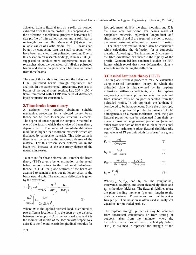
Figure 2 (d) IBOUOBCL3MR
Figure 2 (e) IBOUOBCL3MR
Figure 2 (f) IBOUYBCL3MR
4.2Test specimens
The experimental program consists of totally twelve
beams of 3000mm span. All the twelve beams are
tested for static load test. A schematic diagram of the
test specimen is shown in Figure 3. The various
beam parameters that are considered, in the present
study, with their designations are presented in Table
3. All the beams are provided with the grid points to
locate the loading points and strain measuring
positions. Strain gauges are pasted to measure the
strains using electrical strain gauges. In the next
section, a detailed experimental setup is explained for
three and four point bend test conditions.
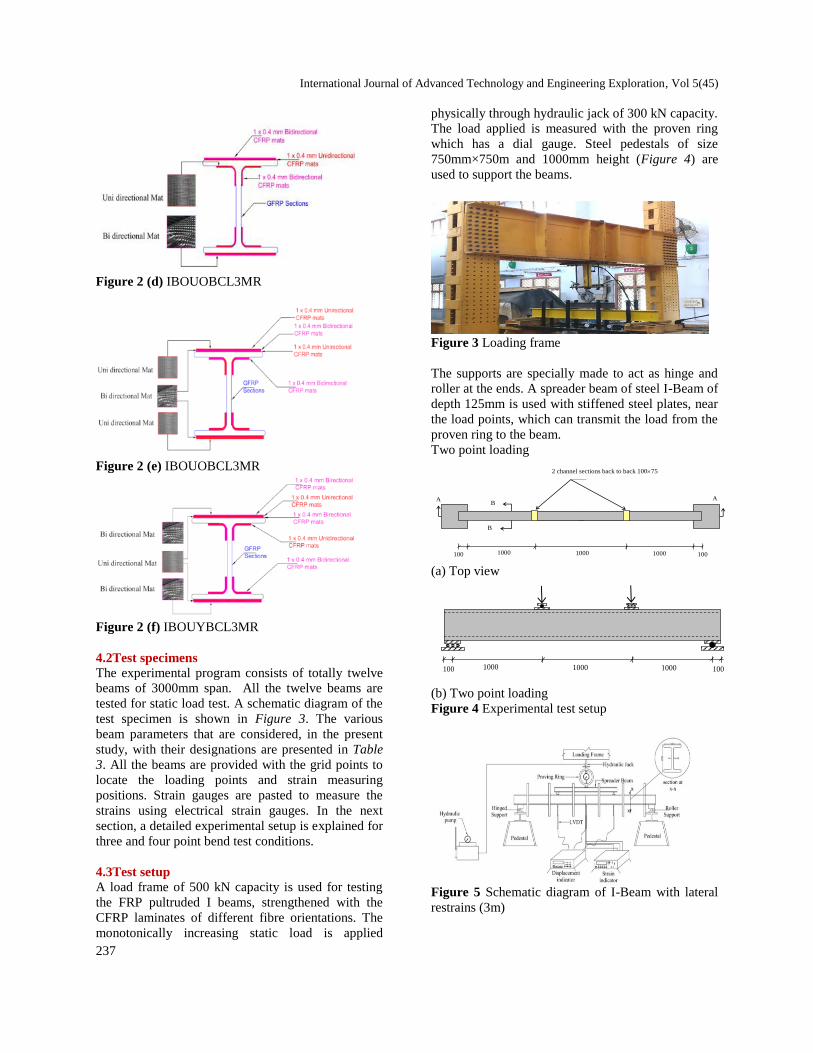
4.3Test setup
A load frame of 500 kN capacity is used for testing
the FRP pultruded I beams, strengthened with the
CFRP laminates of different fibre orientations. The
monotonically increasing static load is applied
physically through hydraulic jack of 300 kN capacity.
The load applied is measured with the proven ring
which has a dial gauge. Steel pedestals of size
750mm×750m and 1000mm height (Figure 4) are
used to support the beams.
Figure 3 Loading frame
The supports are specially made to act as hinge and
roller at the ends. A spreader beam of steel I-Beam of
depth 125mm is used with stiffened steel plates, near
the load points, which can transmit the load from the
proven ring to the beam.
Two point loading
100 1000 1000 1000 100
2 channel sections back to back 10075
A B
B
A
(a) Top view
(b) Two point loading
Figure 4 Experimental test setup
Figure 5 Schematic diagram of I-Beam with lateral
restrains (3m)
Ganesan and Kumaran
238
Literature studies revealed that the use of additional
lateral restrains can solve the problem of lateral
torsional buckling.
Additional lateral restraints are given to the flanges
along the span direction at six equal intervals of all
the I-beams. This frame is fabricated using steel
hollow tubes of 40mm × 40mm × 3mm with 470mm
spacings. This entire frame is supported on saddle
supports and it is isolated from beam supports. The
schematic diagram of the frame setup is shown in
Figure 5. The deformations are measured using the
linear variable displacement transducer (LVDT) with
a least count of 0.01mm of 100mm traverse length at
three different places, viz., one-third span, mid span
and two-third span. A standing adjustable frame is
made to hold the LVDT at the required places. All
the deformations are measured using a multi-channel
digital data acquisition system.
In this experimental setup, the lateral restraints are
introduced in order to access its flexural properties
exactly. The previous study reveals that open sections
are susceptible to lateral torsional buckling.
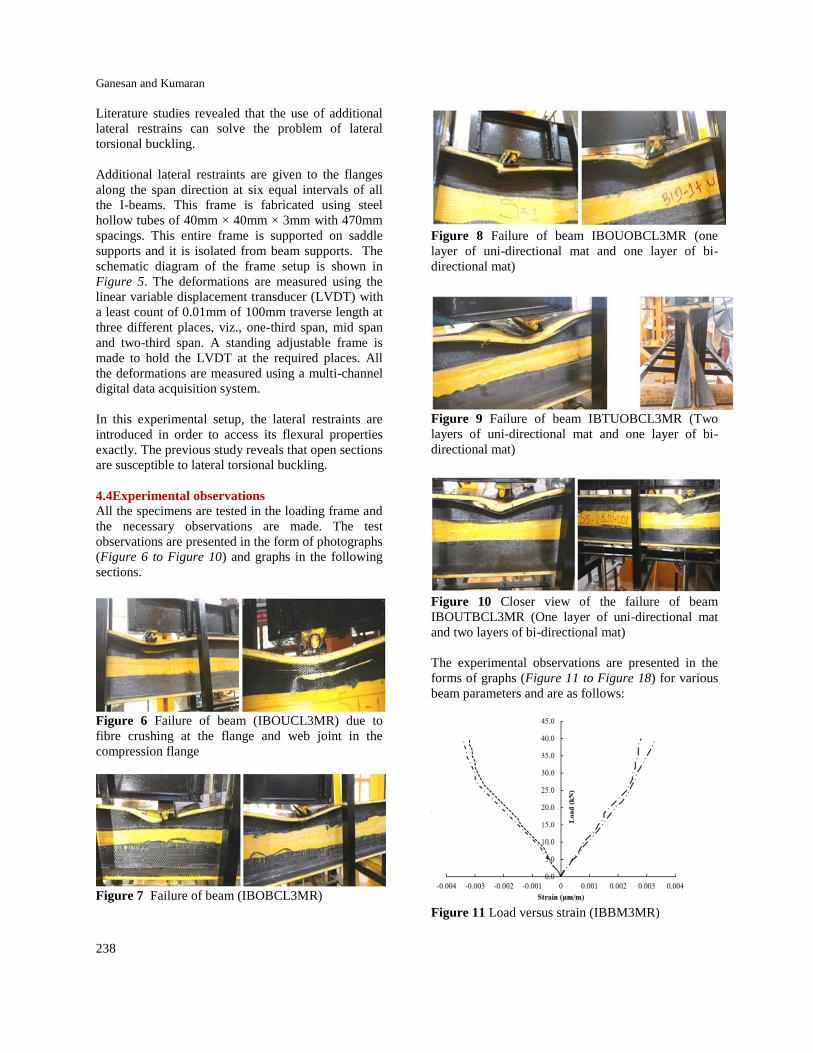
4.4Experimental observations
All the specimens are tested in the loading frame and
the necessary observations are made. The test
observations are presented in the form of photographs
(Figure 6 to Figure 10) and graphs in the following
sections.
Figure 6 Failure of beam (IBOUCL3MR) due to
fibre crushing at the flange and web joint in the
compression flange
Figure 7 Failure of beam (IBOBCL3MR)
Figure 8 Failure of beam IBOUOBCL3MR (one
layer of uni-directional mat and one layer of bi-
directional mat)
Figure 9 Failure of beam IBTUOBCL3MR (Two
layers of uni-directional mat and one layer of bi-
directional mat)
Figure 10 Closer view of the failure of beam
IBOUTBCL3MR (One layer of uni-directional mat
and two layers of bi-directional mat)
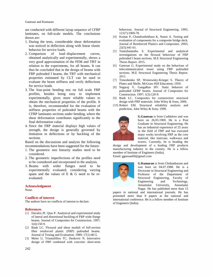
The experimental observations are presented in the
forms of graphs (Figure 11 to Figure 18) for various
beam parameters and are as follows:
Figure 11 Load versus strain (IBBM3MR)

International Journal of Advanced Technology and Engineering Exploration, Vol 5(45)
239
Figure 12 Load versus strain (IBOUCL3MR)
Figure 13 Load versus strain (IBOBCL3MR)
Figure 14 Load versus strain (IBOUOBCL3MR)
Figure 15 Load versus strain (IBTUOBCL3MR)
Figure 16 Load versus strain (IBOUTBCL3MR)
Figure 17 Moment versus curvature

Ganesan and Kumaran
240
Figure 18 Stress versus strain
5.Validation of theoretical computation In order to validate the theoretical computation of
shear stiffness (kAG) values by micro-mechanical
approach, three point bending tests were carried out
on all the six profiles. Experimentally, the shear
stiffness was computed using Nagaraj and GangaRao
[8] approach.
The expression for total deflection in the three
point bending test is given by
(14)
Where EI was obtained experimentally from the four
point bending tests and by substituting and EI in
the above expression, kAG is calculated and the
results are compared with the theoretical values.
Table 3 Computation of kAG using experimental results
BEAM EI×1011N.MM2 MM kAG(E) N×106 kAG(T)N ×106 % VARIATION
IBBM3MR 6.227 27.65 4.22 4.039 4.5
IBOUCL3MR 7.204 53.1 4.39 4.039 8.7
IBOBCL3MR 6.716 46.8 4.309 4.039 6.7
IBOUOBCL3MR 7.693 51.25 4.44 4.039 9.9
IBTUOBCL3MR 8.670 61.85 4.24 4.039 5.1
IBOUTBCL3MR 8.181 53 4.41 4.039 9.2
6.Comparison of theoretical and
experimental results The flexural stiffness of beams made of FRP
pultruded I beams with and without CFRP laminates
is evaluated experimentally and analytically.
Comparison in terms of load mid span displacement
curves, obtained from the 4-point bending test on
beams is shown in Figures 19 to 24.
Figure 19 Load versus deflection (IBBM3MR)
Figure 20 Load versus deflection (IBBM3MR)
The figures clearly states that the curves obtained
experimentally and the straight lines obtained by
TBT agree closely with the beam stiffness. It can be
noted, from the figures, that the analytical results
from TBT practically coincide with the experimental
results for the beams with 3000 mm spans,
corresponding to the ratio (L/D)2as 225.

International Journal of Advanced Technology and Engineering Exploration, Vol 5(45)
241
Figure 21 Load versus deflection (IBOBCL3MR)
Figure 22 Load versus deflection (IBOUOBCL3MR)
Figure 23 Load versus deflection (IBOUOBCL3MR)
Figure 24 Load versus deflection (IBTUOBCL3MR)
In the experimental program, four-point and three
point bend tests are initially performed initially. Two
full scale I beam profiles were used. A methodology
was used to obtain longitudinal and shear modulus of
the section simultaneously. During the tests,
considerable shear deformation was noticed in
deflection along with linear elastic behavior for
service loads.
Classic laminate theory, Rule of mixtures and
Halphin and Tsai equations were used to arrive the
mechanical properties of the profile material.
Analysis of the GFRP beam was also carried out by
finite element method (FEM) and TBT. The
longitudinal elastic modulus was arrived by direction
test and the values obtained are not close to the
values obtained on full scale beam test.
Comparison of load-displacement curves, obtained,
analytically and experimentally, shows a very good
approximation of the FEM and TBT in relation to the
experiments, for all beams. It can thus be concluded
that in the design of beams with FRP pultruded I
beams, the TBT with mechanical properties estimated
by CLT can be used to evaluate the beam stiffness
and verify deflections for service loads. However, for
estimation of the mechanical properties, the
individual properties of fibres and resin, the fibre
volume fraction, and the composition of all laminates
should be reasonably accurate.
On the other hand, the four-point bending test on full
scale FRP profiles, besides being easy to implement
experimentally, gives more reliable values to obtain
the mechanical properties of the profile. It is,
therefore, recommended for the evaluation of
stiffness properties of pultruded beams with the
CFRP laminates sections under bending, where the
shear deformation contributes significantly to the
final deformation value. Similar endings have also
been noticed in the research carried out by [8− ].
Mentioning about the significance of verifying global
unsteadiness modes in the design of open walled
section is inevitable in this study. For the profile
used in this study, the performed linear flexural
analyses, using the FEM, is also necessary to verify
the final limit state. However, since the FRP material
displays high values of strength, the design is
generally governed by limitation in deflections or by
buckling of the sections.
7.Conclusion In this study, the structural behaviour of GFRP
pultruded profiles reinforced with CFRP laminates on
the flanges is observed. The mechanical properties
are obtained from the specimen extracted from the
flanges. Tests of three-point and four-points twisting
Ganesan and Kumaran
242
are conducted with different layup sequence of CFRP
laminates, on full-scale models. The conclusions
drawn are:
1. During the tests, considerable shear deformation
was noticed in deflection along with linear elastic
behavior for service loads.
2. Comparison of load–displacement curves,
obtained analytically and experimentally, shows a
very good approximation of the FEM and TBT in
relation to the experiments, for all beams. It can
thus be concluded that in the design of beams with
FRP pultruded I beams, the TBT with mechanical
properties estimated by CLT can be used to
evaluate the beam stiffness and verify deflections
for service loads.
3. The four-point bending test on full scale FRP
profiles, besides being easy to implement
experimentally, gives more reliable values to
obtain the mechanical properties of the profile. It
is, therefore, recommended for the evaluation of
stiffness properties of pultruded beams with the
CFRP laminates sections under bending, where the
shear deformation contributes significantly to the
final deformation value.
4. Since the FRP material displays high values of
strength, the design is generally governed by
limitation in deflections or by buckling of the
sections.
Based on the discussions and analysis the following
recommendations have been suggested for the future:
1. The geometric non linearity studies need to be
considered.
2. The geometric imperfections of the profiles need
to be considered and incorporated in the analysis.
3. Beams with wider flanges need to be
experimentally evaluated, considering varying
spans and the values of E & G need to be re-
evaluated.
Acknowledgment None.
Conflicts of interest The authors have no conflicts of interest to declare.
References [1] Davalos JF, Qiao P. Analytical and experimental study
of lateral and distortional buckling of FRP wide-flange
beams. Journal of Composites for Construction. 1997;
1(4):150-9.
[2] Bank LC. Flexural and shear moduli of full-section
fiber reinforced plastic (FRP) pultruded beams.
Journal of Testing and Evaluation. 1989; 17(1):40-5.
[3] Meier U, Triantafillou TC, Deskovic N. Innovative
design of FRP combined with concrete: short-term
behaviour. Journal of Structural Engineering. 1995;
121(7):1069-78.
[4] Kumar P, Chandrashekhara K, Nanni A. Testing and
evaluation of components for a composite bridge deck.
Journal of Reinforced Plastics and Composites. 2003;
22(5):441-61.
[5] Tamizhamuthu S. Experimental and analytical
investigations on the flexural behaviour of FRP
pultruded I beam sections. M.E Structural Engineering
Thesis Report. 2015.
[6] Ganesan G. Experimental study on the behaviour of
telecommunication tower using FRP pultruded
sections. M.E Structural Engineering Thesis Report.
2011.
[7] Timoshenko SP, Woinowsky-Krieger S. Theory of
Plates and Shells. McGraw-Hill Education; 1959.
[8] Nagaraj V, GangaRao HV. Static behavior of
pultruded GFRP beams. Journal of Composites for
Construction. 1997; 1(3):120-9.
[9] Bank LC. Composites for construction: structural
design with FRP materials. John Wiley & Sons; 2006.
[10] Robert EM. Structural reliability analysis and
prediction. John Wiley & Sons; 1999.
G.Ganesan is from Cuddalore and was
born on 26.05.1969. He is a Post
Graduate in Structural Engineering. He
has an industrial experience of 25 years
in the field of FRP and has executed
many works involving FRP as the core
material, like staircase, walkways and
towers. Currently, he is heading the
design and development of a leading FRP products
manufacturing industry in the country. He is a fellow
member of Institute of Engineers (India).
Email: [email protected]
G.Kumaran is from Chidambaram and
was born on 04.07.1968. He is a
Doctorate in Structural Engineering and
Professor of the Department of
Structural Engineering, Faculty of
Engineering and Technology,
Annamalai University, Annamalai
Nagar. He has published more than 15
papers in national and international journals. He has
presented more than 8 papers at the national and
international conference. He is a fellow member of Institute
of Engineers (India).
Related Documents


