arXiv:2202.04602v1 [eess.SP] 9 Feb 2022 1 An Experimental Proof of Concept for Integrated Sensing and Communications Waveform Design Tongyang Xu, Member, IEEE, Fan Liu, Member, IEEE, Christos Masouros, Senior Member, IEEE and Izzat Darwazeh, Senior Member, IEEE Abstract—The integration of sensing and communication (ISAC) functionalities have recently gained significant research interest as a hardware-, power-, spectrum- and cost- efficient solution. This experimental work focuses on a dual-functional radar sensing and communication framework where a single radiation waveform, either omnidirectional or directional, can realize both radar sensing and communication functions. We study a trade-off approach that can balance the performance of communications and radar sensing. We design an orthogonal frequency division multiplexing (OFDM) based multi-user multi- ple input multiple output (MIMO) software-defined radio (SDR) testbed to validate the dual-functional model. We carry out over- the-air experiments to investigate the optimal trade-off factor to balance the performance for both functions. On the radar perfor- mance, we measure the output beampatterns of our transmission to examine their similarity to simulation based beampatterns. On the communication side, we obtain bit error rate (BER) results from the testbed to show the communication performance using the dual-functional waveform. Our experiment reveals that the dual-functional approach can achieve comparable BER performance with pure communication-based solutions while maintaining fine radar beampatterns simultaneously. Index Terms—Communications, radar, sensing, integrated sensing and communications (ISAC), waveform design, OFDM, MIMO, software defined radio (SDR), over-the-air, prototyping. I. I NTRODUCTION W IRELESS communications have evolved from 1G to 5G with significant technology innovations. Tradition- ally, signals are transmitted at low-frequency carriers with narrow signal bandwidth due to limitations from hardware and technical theories. Nowadays, signals can be transmitted at millimeter wave (mmWave) frequency [1] and TeraHertz (THz) frequency [2] with GHz signal bandwidth. In terms of antennas, communication systems can integrate hundreds of antennas in massive multiple input multiple output (MIMO) [3]. Moreover, in terms of signal waveform, different op- tions are available such as code division multiple access (CDMA) in 3G [4], orthogonal frequency division multiplex- ing (OFDM) and single carrier frequency division multiple access (SC-FDMA) in 4G/5G [5], [6]. Recently, advanced T. Xu, C. Masouros and I. Darwazeh are with the Department of Electronic and Electrical Engineering, University College London (UCL), London, WC1E 7JE, UK (e-mail: [email protected], [email protected], [email protected]). Fan Liu is with the Department of Electical and Electronic Engineering, Southern University of Science and Technology, Shenzhen, China. e-mail: [email protected]. This work was supported by the Engineering and Physical Sciences Research Council (EPSRC) general Grant EP/S028455/1. waveform candidates are being investigated for future 6G such as spectrally efficient frequency division multiplexing (SEFDM) [7], faster than Nyquist (FTN) [8], orthogonal time frequency space (OTFS) [9], generalized frequency division multiplexing (GFDM) [10] and filterbank based multicarrier (FBMC) [11]. Complementary to wireless communications, various sen- sors have been used to sense the world such as accelerometers, Gyroscope, light sensor, temperature sensors, audio and video. Due to the ubiquitous features of wireless signals, smart ap- plications such as non-intrusive and non-contact radar sensing and radio frequency (RF) sensing are becoming popular. In [12], Google develops a mmWave radar sensing system at 60 GHz termed ‘Soli’, which can sense and understand subtle motions in finger gestures. Work in [13] tests different radar and sonar devices for detecting different classes of mobility via measuring micro-Doppler [14] sensitivity. In [15], a joint detection system that integrates a camera with an frequency- modulated continuous wave (FMCW) radar is designed to realize object detection and 3D estimation. In [16], a ultra- wideband (UWB) MIMO radar equipped with manufactured Vivaldi antennas is designed and implemented to detect ob- jects behind walls using stepped-frequency continuous wave (SFCW) signals. Moreover, the variations of reflected signals can judge human motions even behind walls. The represen- tative work is [17], where a special method, termed inverse synthetic aperture radar (ISAR), is applied to deal with a moving object using a single receiver antenna. Recently, an IEEE group is working on an IEEE 802.11bf standard [18], which aims to use existing wireless fidelity (WiFi) signals to realize sensing functions. There are commonly two methods for estimating human activities based on WiFi signals, namely received signal strength indicator (RSSI) [19], [20], [21], [22] and channel state information (CSI) [23]. Although RSSI has been successful in human activity detections, its coarse sensing resolution and high sensitivity to noise limit its applications in further areas. The second solution, CSI, aims to extract amplitude [24] and phase information [25], [26] to better assist human activity detections. In [27], a WiFall system is designed to ‘see’ human activities via measuring CSI. A detailed prop- agation model is analytically studied to reveal the possibility of detecting human fall activities. In [28], a WiHear system is designed to ‘hear’ human talks based on micro-movement via radio reflections from mouth movements. In [29], CSI information is extracted from both OFDM signals and MIMO antennas. Therefore, detection accuracy is improved. In [30], CSI from WiFi signals is extracted for monitoring vital signs

Welcome message from author
This document is posted to help you gain knowledge. Please leave a comment to let me know what you think about it! Share it to your friends and learn new things together.
Transcript
arX
iv:2
202.
0460
2v1
[ee
ss.S
P] 9
Feb
202
21
An Experimental Proof of Concept for Integrated
Sensing and Communications Waveform DesignTongyang Xu, Member, IEEE, Fan Liu, Member, IEEE, Christos Masouros, Senior Member, IEEE and Izzat
Darwazeh, Senior Member, IEEE
Abstract—The integration of sensing and communication(ISAC) functionalities have recently gained significant researchinterest as a hardware-, power-, spectrum- and cost- efficientsolution. This experimental work focuses on a dual-functionalradar sensing and communication framework where a singleradiation waveform, either omnidirectional or directional, canrealize both radar sensing and communication functions. Westudy a trade-off approach that can balance the performanceof communications and radar sensing. We design an orthogonalfrequency division multiplexing (OFDM) based multi-user multi-ple input multiple output (MIMO) software-defined radio (SDR)testbed to validate the dual-functional model. We carry out over-the-air experiments to investigate the optimal trade-off factor tobalance the performance for both functions. On the radar perfor-mance, we measure the output beampatterns of our transmissionto examine their similarity to simulation based beampatterns.On the communication side, we obtain bit error rate (BER)results from the testbed to show the communication performanceusing the dual-functional waveform. Our experiment revealsthat the dual-functional approach can achieve comparable BERperformance with pure communication-based solutions whilemaintaining fine radar beampatterns simultaneously.
Index Terms—Communications, radar, sensing, integratedsensing and communications (ISAC), waveform design, OFDM,MIMO, software defined radio (SDR), over-the-air, prototyping.
I. INTRODUCTION
W IRELESS communications have evolved from 1G to
5G with significant technology innovations. Tradition-
ally, signals are transmitted at low-frequency carriers with
narrow signal bandwidth due to limitations from hardware
and technical theories. Nowadays, signals can be transmitted
at millimeter wave (mmWave) frequency [1] and TeraHertz
(THz) frequency [2] with GHz signal bandwidth. In terms of
antennas, communication systems can integrate hundreds of
antennas in massive multiple input multiple output (MIMO)
[3]. Moreover, in terms of signal waveform, different op-
tions are available such as code division multiple access
(CDMA) in 3G [4], orthogonal frequency division multiplex-
ing (OFDM) and single carrier frequency division multiple
access (SC-FDMA) in 4G/5G [5], [6]. Recently, advanced
T. Xu, C. Masouros and I. Darwazeh are with the Department of Electronicand Electrical Engineering, University College London (UCL), London,WC1E 7JE, UK (e-mail: [email protected], [email protected],[email protected]).
Fan Liu is with the Department of Electical and Electronic Engineering,Southern University of Science and Technology, Shenzhen, China. e-mail:[email protected].
This work was supported by the Engineering and Physical SciencesResearch Council (EPSRC) general Grant EP/S028455/1.
waveform candidates are being investigated for future 6G
such as spectrally efficient frequency division multiplexing
(SEFDM) [7], faster than Nyquist (FTN) [8], orthogonal time
frequency space (OTFS) [9], generalized frequency division
multiplexing (GFDM) [10] and filterbank based multicarrier
(FBMC) [11].
Complementary to wireless communications, various sen-
sors have been used to sense the world such as accelerometers,
Gyroscope, light sensor, temperature sensors, audio and video.
Due to the ubiquitous features of wireless signals, smart ap-
plications such as non-intrusive and non-contact radar sensing
and radio frequency (RF) sensing are becoming popular. In
[12], Google develops a mmWave radar sensing system at 60
GHz termed ‘Soli’, which can sense and understand subtle
motions in finger gestures. Work in [13] tests different radar
and sonar devices for detecting different classes of mobility
via measuring micro-Doppler [14] sensitivity. In [15], a joint
detection system that integrates a camera with an frequency-
modulated continuous wave (FMCW) radar is designed to
realize object detection and 3D estimation. In [16], a ultra-
wideband (UWB) MIMO radar equipped with manufactured
Vivaldi antennas is designed and implemented to detect ob-
jects behind walls using stepped-frequency continuous wave
(SFCW) signals. Moreover, the variations of reflected signals
can judge human motions even behind walls. The represen-
tative work is [17], where a special method, termed inverse
synthetic aperture radar (ISAR), is applied to deal with a
moving object using a single receiver antenna. Recently, an
IEEE group is working on an IEEE 802.11bf standard [18],
which aims to use existing wireless fidelity (WiFi) signals to
realize sensing functions. There are commonly two methods
for estimating human activities based on WiFi signals, namely
received signal strength indicator (RSSI) [19], [20], [21], [22]
and channel state information (CSI) [23]. Although RSSI has
been successful in human activity detections, its coarse sensing
resolution and high sensitivity to noise limit its applications
in further areas. The second solution, CSI, aims to extract
amplitude [24] and phase information [25], [26] to better assist
human activity detections. In [27], a WiFall system is designed
to ‘see’ human activities via measuring CSI. A detailed prop-
agation model is analytically studied to reveal the possibility
of detecting human fall activities. In [28], a WiHear system
is designed to ‘hear’ human talks based on micro-movement
via radio reflections from mouth movements. In [29], CSI
information is extracted from both OFDM signals and MIMO
antennas. Therefore, detection accuracy is improved. In [30],
CSI from WiFi signals is extracted for monitoring vital signs
2
and postures during sleeping.
It is noted that traditional radar signals are not initially
designed for communications. Conversely, signalling for com-
munications is not inherently designed to serve sensing func-
tionalities. To achieve the joint sensing and communication
purpose, communication radio signals and radar sensing sig-
nals have to be managed in time division multiplexing (TDM)
mode, frequency division multiplexing (FDM) mode or space
division multiplexing (SDM) mode. However, the multiplex-
ing strategy will waste time, frequency or spatial resources.
A number of approaches have emerged, aiming to design
and test signalling that is appropriate for integrated sensing
and communication (ISAC). Work in [31] proposed to use
primary synchronization signal (PSS) in the LTE frame for
the radar sensing purpose. Work in [32] proposed a space
division multiple access (SDMA) scheme that can support
radar and communications using the same transmit hardware
with the same timing and spectral occupation. The principle
behind the work is to send spatially orthogonal beams at
the null space of the other one. Therefore, interference is
avoided. This was further demonstrated experimentally in [33],
where analog-domain phased array antennas were employed
to assist radar beam tracking and alignment. Work in [34]
studied a new waveform design in ISAC. The principle is to
multiplex low out-of-band power emission signals with radar
signals in frequency domain. However, this is a frequency
multiplexing scheme and is not a dual-functional design. In
addition, its experiment is based on single-antenna point to
point links. Work in [35] proposed to use mutually orthogonal
waveforms via space time coding (STC) in different beams for
communication and radar rather than a single waveform beam.
Work in [36] aims to realize joint communication and radar
functions in a FDM mode via full-duplex in hardware based
solutions. Work in [37] designs a joint communication-radar
experiment using single-carrier signals in a TDM mode via
full-duplex radar reception. Work in [38] proposed to achieve
joint communication and radar functions by modulating in-
formation signalling onto standard radar waveforms through
index modulation.
The main contribution of this work is to practically design
and test over-the-air for the first time, a joint dual-functional
radar communication waveform [39] for an integrated radar
sensing and multi-user MIMO-OFDM communication system
[40]. Unlike existing work, the prototyping testbed in this
paper can realize radar and communication using the same
time, frequency and spatial resources. As a step ahead from
[39], the designed dual-functional ISAC experiment in this
work is based on the OFDM signal waveform, which enables
a straightforward deployment of the ISAC framework in many
standard communication systems. Additionally, unlike pure
theoretical simulations, this work obtains a practically working
radar and communication trade-off factor that ensures radar
beampattern quality and communication performance after
comprehensive experiments on communication constellation
diagrams, bit error rate (BER), error vector magnitude (EVM)
and radar beampattern quality.
The rest of this paper is organized as follows. Section II will
introduce the fundamentals of signal waveforms and multi-
antenna communication architectures. In Section III, the trade-
off between radar sensing and communication is explained
using the ISAC model, followed by the radar beampattern
illustrations in pure radar and pure communication systems.
A multi-user MIMO-OFDM experiment is designed and im-
plemented in Section IV to verify the ISAC framework in
hardware. Finally, Section V concludes the work.
II. COMMUNICATION MODEL
We consider a mutli-user MIMO-OFDM transmission, for
which the received signal can be expressed as
Y = HX+W, (1)
where H = [h1,h2, ...,hN] ∈ CK×N indicates a MIMO
channel matrix with K being the number of receiver side
users and N being the number of transmitter side antennas.
X = [x1,x2, ...,xL] ∈ CN×L is the transmission symbol
matrix after precoding, with L being the number of time
samples per data stream on each antenna. Similarly, the noise
matrix W = [w1,w2, ...,wL] ∈ CK×L indicates K parallel
noise vectors for K receiver side users with L noise samples
per user.
The commonly used multicarrier signal format in 4G, 5G
and WiFi standards is OFDM, which we employ in this
work. Traditionally, each antenna is responsible for an OFDM
symbol stream. Therefore, the symbol transmission matrix
consists of N parallel OFDM data streams with L time
samples for each data stream. The expression in (1) can be
rewritten as
Y = X+ (HX−X)︸ ︷︷ ︸
MUI
+W, (2)
where X ∈ CK×L indicates the user side multicarrier symbol
matrix. The second term in (2) represents the multi-user
interference (MUI) term and the total power contributed by
the MUI terms is computed as
PMUI =∥∥∥HX−X
∥∥∥
2
F, (3)
where ‖· ‖F denotes the Frobenius matrix norm. The value
of PMUI determines the value of signal-to-interference-plus-
noise ratio (SINR). In order to have high throughput, the SINR
should be maximized by minimizing the value of PMUI .
An OFDM signal is expressed as
Xk =1√Q
M∑
m=1
sm exp
(j2πmk
Q
)
, (4)
where Xk is the time sample with the index of k = 1, 2, ..., Q,
M is the number of sub-carriers, Q = ρM indicates the
number of time samples and ρ is the oversampling factor. It
is noted that M≤L. 1√Q
is the normalization factor and sm is
the mth single-carrier symbol in one OFDM symbol.
A matrix format can convert the expression in (4) to the
following
3
X = FS, (5)
where F ∈ CQ×M indicates a sub-carrier matrix with elements
noted as exp( j2πmkQ
) and S ∈ CM×1 indicates the symbol
vector with elements noted as sm. The received signal, con-
taminated by additive white Gaussian noise (AWGN), Z , is
expressed as
Y = FS + Z, (6)
where Y ∈ CQ×1 indicates one OFDM symbol. For an OFDM
frame, we need to generate multiple OFDM symbols with
overall L time samples. In order to support a MIMO system
defined in (1), we need K parallel OFDM signal generators. In
this case, the user side symbol matrix X ∈ CK×L is obtained.
In the following, we will discuss the methodology of precoding
X ∈ CK×L to the dual-functional radar communication
waveform X ∈ CN×L.
III. TRADE-OFF BETWEEN RADAR SENSING AND
COMMUNICATIONS
To realize a dual-functional radar communication function,
we employ the optimization methodology from [39] where a
trade-off factor γ is introduced to balance the performance of
the communication part and the radar part. In this case, the
resulting waveform can provide a balanced solution to both
communications and radar waveform.
We define the desired radar transmit signal as Xd where its
design is detailed in [41]. The trade-off optimization problem
considering the total power constraint is formulated as
minX
γ∥∥∥HX−X
∥∥∥
2
F+ (1− γ)
∥∥∥X−Xd
∥∥∥
2
F
s.t.1
L
∥∥∥X
∥∥∥
2
F= PT ,
(7)
where the first term,
∥∥∥HX−X
∥∥∥
2
Faims to minimize the
MUI while the second term
∥∥∥X−Xd
∥∥∥
2
Faims to enforce the
signal waveform to approach the desired radar waveform Xd.
0 ≤ γ ≤ 1 indicates the trade-off factor that balances the
communication and radar performance.
In general, there are two types of MIMO radar waveform
designs. One is the orthogonal waveform, which generates
omni-directional beampattern for searching unknown targets.
Alternatively, MIMO radar may also track known targets via
directional waveforms [42]. Without loss of generality, in
this paper we show that the proposed approach is capable
of designing both orthogonal and directional MIMO radar
waveforms while carrying communication information, which
will be validated by experimental results.
We can expand the two Frobenius norms and combine them
in a single norm format as
γ∥∥∥HX−X
∥∥∥
2
F+ (1− γ)
∥∥∥X−Xd
∥∥∥
2
F
=∥∥∥[√γHT ,
√
1− γIN ]T X− [√γXT ,
√
1− γXTd ]
T∥∥∥
2
F.
(8)
To simplify the expression, we define A =[√γHT ,
√1− γIN ]T ∈ C
(K+N)×N , B =[√γXT ,
√1− γXT
d ]T ∈ C(K+N)×L. Therefore, (7) can
be reformulated as
minX
∥∥∥AX−B
∥∥∥
2
F
s.t.
∥∥∥X
∥∥∥
2
F= LPT .
(9)
While problem (9) is non-convex due to the quadratic
equality constraint, it can be proved that strong duality holds,
such that (9) can be optimally solved via solving the dual
problem [39]. To reduce the complexity incurred by the
iterative algorithm of solving the dual problem, we consider a
closed-form sub-optimal solution, which is obtained by using
the simple least square method under the total power constraint
as the following
X =
√LPT
‖A†B‖FA
†B, (10)
where (·)† represents the pseudo inverse of the matrix. To
illustrate the trade-off performance for the omnidirectional
beampattern and directional beampattern designs, we will use
‘Pure-Radar-Omni’ and ‘Pure-Radar-Dir’ to represent pure
omnidirectional and directional radar beampattern, respec-
tively. We will use ‘Pure-Com’ to represent the radar beampat-
tern when pure communication is enabled. For dual-functional
radar communication systems, we will use terms ‘RadarCom-
Omni’ and ‘RadarCom-Dir’ correspondingly.
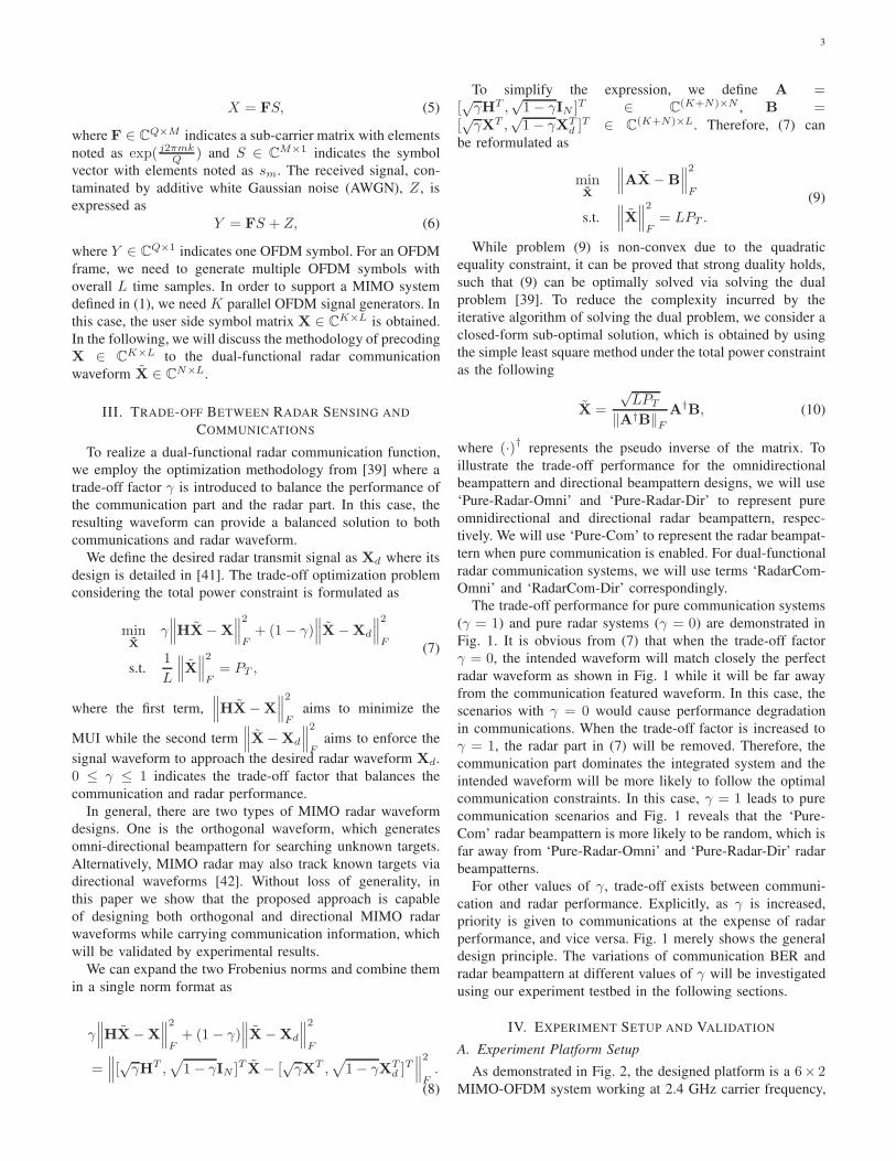
The trade-off performance for pure communication systems
(γ = 1) and pure radar systems (γ = 0) are demonstrated in
Fig. 1. It is obvious from (7) that when the trade-off factor
γ = 0, the intended waveform will match closely the perfect
radar waveform as shown in Fig. 1 while it will be far away
from the communication featured waveform. In this case, the
scenarios with γ = 0 would cause performance degradation
in communications. When the trade-off factor is increased to
γ = 1, the radar part in (7) will be removed. Therefore, the
communication part dominates the integrated system and the
intended waveform will be more likely to follow the optimal
communication constraints. In this case, γ = 1 leads to pure
communication scenarios and Fig. 1 reveals that the ‘Pure-
Com’ radar beampattern is more likely to be random, which is
far away from ‘Pure-Radar-Omni’ and ‘Pure-Radar-Dir’ radar
beampatterns.
For other values of γ, trade-off exists between communi-
cation and radar performance. Explicitly, as γ is increased,
priority is given to communications at the expense of radar
performance, and vice versa. Fig. 1 merely shows the general
design principle. The variations of communication BER and
radar beampattern at different values of γ will be investigated
using our experiment testbed in the following sections.
IV. EXPERIMENT SETUP AND VALIDATION
A. Experiment Platform Setup
As demonstrated in Fig. 2, the designed platform is a 6× 2MIMO-OFDM system working at 2.4 GHz carrier frequency,
4
-80 -60 -40 -20 0 20 40 60 80
(deg)
-15
-10
-5
0
5
10
Bea
mpa
ttern
(dB
i)
Pure-Radar-DirPure-Radar-OmniPure-Com
Fig. 1. Radar beampattern illustration for pure communication systems (γ=1) and pure radar systems (γ=0) considering OFDM communicationsignals and directional/omnidirectional radar beampatterns.
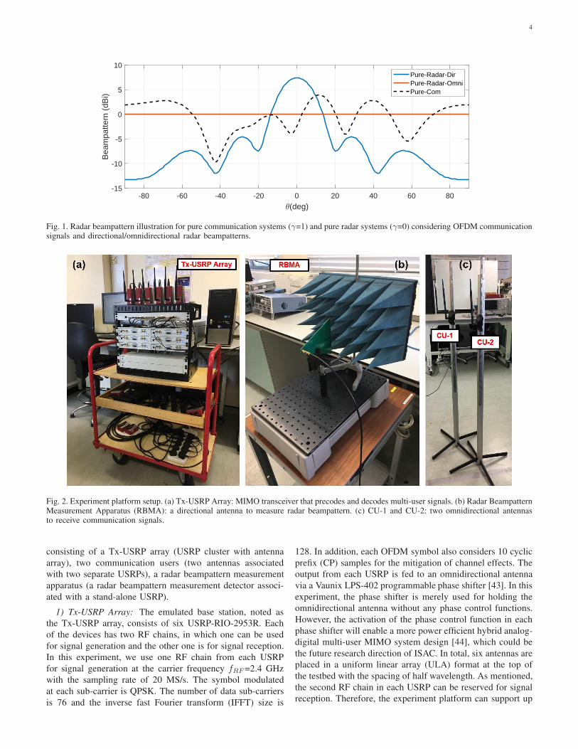
Fig. 2. Experiment platform setup. (a) Tx-USRP Array: MIMO transceiver that precodes and decodes multi-user signals. (b) Radar BeampatternMeasurement Apparatus (RBMA): a directional antenna to measure radar beampattern. (c) CU-1 and CU-2: two omnidirectional antennasto receive communication signals.
consisting of a Tx-USRP array (USRP cluster with antenna
array), two communication users (two antennas associated
with two separate USRPs), a radar beampattern measurement
apparatus (a radar beampattern measurement detector associ-
ated with a stand-alone USRP).
1) Tx-USRP Array: The emulated base station, noted as
the Tx-USRP array, consists of six USRP-RIO-2953R. Each
of the devices has two RF chains, in which one can be used
for signal generation and the other one is for signal reception.
In this experiment, we use one RF chain from each USRP
for signal generation at the carrier frequency fRF =2.4 GHz
with the sampling rate of 20 MS/s. The symbol modulated
at each sub-carrier is QPSK. The number of data sub-carriers
is 76 and the inverse fast Fourier transform (IFFT) size is
128. In addition, each OFDM symbol also considers 10 cyclic
prefix (CP) samples for the mitigation of channel effects. The
output from each USRP is fed to an omnidirectional antenna
via a Vaunix LPS-402 programmable phase shifter [43]. In this
experiment, the phase shifter is merely used for holding the
omnidirectional antenna without any phase control functions.
However, the activation of the phase control function in each
phase shifter will enable a more power efficient hybrid analog-
digital multi-user MIMO system design [44], which could be
the future research direction of ISAC. In total, six antennas are
placed in a uniform linear array (ULA) format at the top of
the testbed with the spacing of half wavelength. As mentioned,
the second RF chain in each USRP can be reserved for signal
reception. Therefore, the experiment platform can support up
5
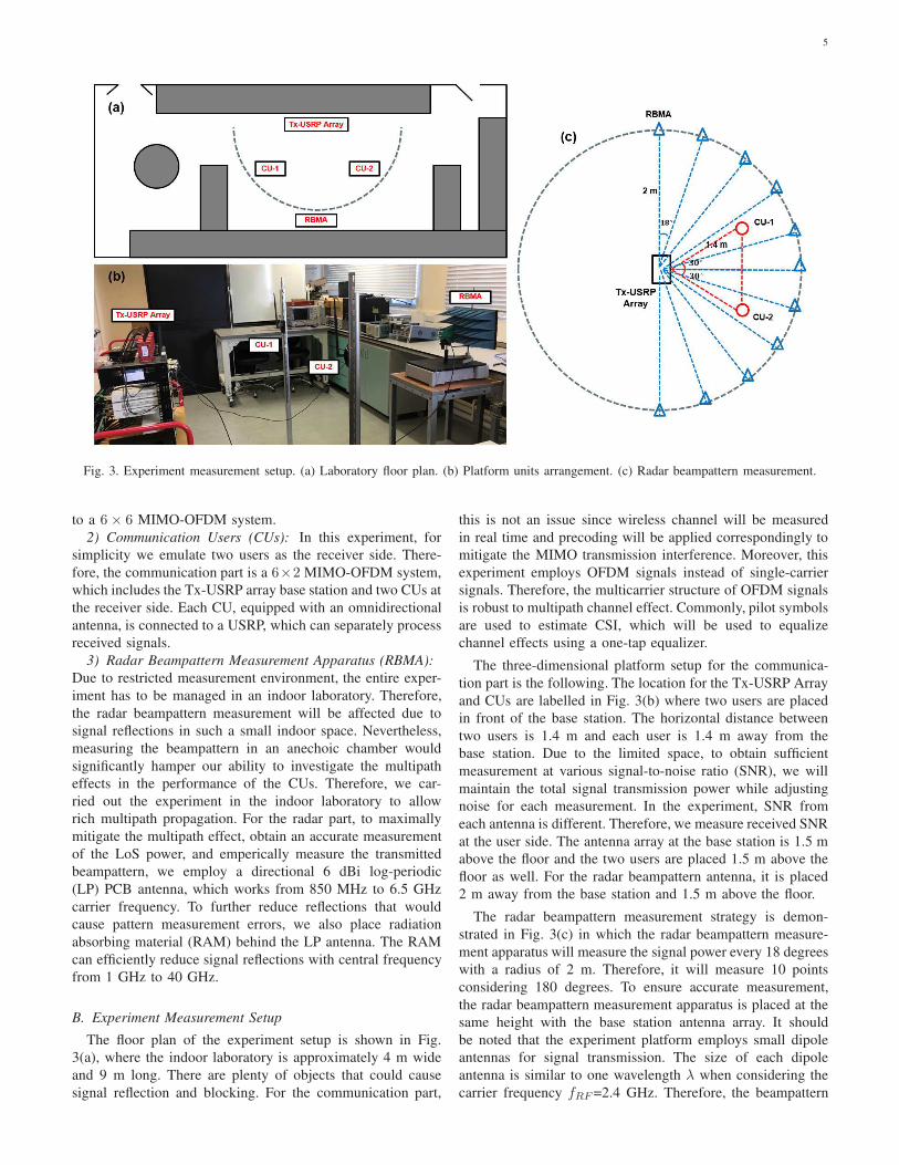
Fig. 3. Experiment measurement setup. (a) Laboratory floor plan. (b) Platform units arrangement. (c) Radar beampattern measurement.
to a 6× 6 MIMO-OFDM system.
2) Communication Users (CUs): In this experiment, for
simplicity we emulate two users as the receiver side. There-
fore, the communication part is a 6×2 MIMO-OFDM system,
which includes the Tx-USRP array base station and two CUs at
the receiver side. Each CU, equipped with an omnidirectional
antenna, is connected to a USRP, which can separately process
received signals.
3) Radar Beampattern Measurement Apparatus (RBMA):
Due to restricted measurement environment, the entire exper-
iment has to be managed in an indoor laboratory. Therefore,
the radar beampattern measurement will be affected due to
signal reflections in such a small indoor space. Nevertheless,
measuring the beampattern in an anechoic chamber would
significantly hamper our ability to investigate the multipath
effects in the performance of the CUs. Therefore, we car-
ried out the experiment in the indoor laboratory to allow
rich multipath propagation. For the radar part, to maximally
mitigate the multipath effect, obtain an accurate measurement
of the LoS power, and emperically measure the transmitted
beampattern, we employ a directional 6 dBi log-periodic
(LP) PCB antenna, which works from 850 MHz to 6.5 GHz
carrier frequency. To further reduce reflections that would
cause pattern measurement errors, we also place radiation
absorbing material (RAM) behind the LP antenna. The RAM
can efficiently reduce signal reflections with central frequency
from 1 GHz to 40 GHz.
B. Experiment Measurement Setup
The floor plan of the experiment setup is shown in Fig.
3(a), where the indoor laboratory is approximately 4 m wide
and 9 m long. There are plenty of objects that could cause
signal reflection and blocking. For the communication part,
this is not an issue since wireless channel will be measured
in real time and precoding will be applied correspondingly to
mitigate the MIMO transmission interference. Moreover, this
experiment employs OFDM signals instead of single-carrier
signals. Therefore, the multicarrier structure of OFDM signals
is robust to multipath channel effect. Commonly, pilot symbols
are used to estimate CSI, which will be used to equalize
channel effects using a one-tap equalizer.
The three-dimensional platform setup for the communica-
tion part is the following. The location for the Tx-USRP Array
and CUs are labelled in Fig. 3(b) where two users are placed
in front of the base station. The horizontal distance between
two users is 1.4 m and each user is 1.4 m away from the
base station. Due to the limited space, to obtain sufficient
measurement at various signal-to-noise ratio (SNR), we will
maintain the total signal transmission power while adjusting
noise for each measurement. In the experiment, SNR from
each antenna is different. Therefore, we measure received SNR
at the user side. The antenna array at the base station is 1.5 m
above the floor and the two users are placed 1.5 m above the
floor as well. For the radar beampattern antenna, it is placed
2 m away from the base station and 1.5 m above the floor.
The radar beampattern measurement strategy is demon-
strated in Fig. 3(c) in which the radar beampattern measure-
ment apparatus will measure the signal power every 18 degrees
with a radius of 2 m. Therefore, it will measure 10 points
considering 180 degrees. To ensure accurate measurement,
the radar beampattern measurement apparatus is placed at the
same height with the base station antenna array. It should
be noted that the experiment platform employs small dipole
antennas for signal transmission. The size of each dipole
antenna is similar to one wavelength λ when considering the
carrier frequency fRF =2.4 GHz. Therefore, the beampattern

6
Fig. 4. Frame and resource block structure for the dual-functional radar and communication multiuser MIMO system.
measurement at a 2 m distance is greater than 2λ [45] and is
practically within the far-field range. In addition, to mitigate
multipath effect to the beampattern measurement, we use a
6 dBi LP PCB antenna, which has a narrow and focused
radiation beam. Therefore, it can focus on the line-of-sight
(LOS) signal collection within its beam range and avoid
potential multipath signal collections from other reflection
directions. For the radar part, we have a stand-alone USRP
for radar beampattern power measurement.
The radar beampattern power computation is based on
received symbols. Since each symbol has real and imaginary
parts, therefore the power will be calculated as
P =1
Q
Q∑
k=1
[ℜ(X(k))2 + ℑ(X(k))2], (11)
where X(k) indicates the kth received complex symbol and1√Q
is the scaling factor for average power computation. ℜ·and ℑ· indicate the real part and imaginary part of a symbol,
respectively.
C. Frame Design and Channel Estimation
1) Frame Structure: The frame structure for this experi-
ment follows the same structure in [40] and is shown in Fig.
4 where 20 resource blocks are combined to form one frame.
The time duration for one frame is 10 ms. The first resource
block is reserved for signalling overhead, which will be used
mainly for MIMO channel estimation. Each resource block
includes seven OFDM symbols and the first resource block has
a unique OFDM symbol allocation scheme. The interference
from MIMO antennas can be solved via transmitter precoding
based on estimated CSI, which indicates the importance of
accurate CSI estimation. To avoid interference to CSI esti-
mation, we multiplex the overhead at each antenna in time-
domain as illustrated in Fig. 4. In this case, even though
the data part is interfered, the overhead part is interference
free. It should be noted that to mitigate potential channel
and hardware imperfections, an additional downlink pilot is
applied for all the data streams.2) MIMO Channel Estimation: Based on the interleaved
overhead structure in Fig. 4, we define a pilot matrix as
P =
p1 0 0 0 0 00 p2 0 0 0 00 0 p3 0 0 00 0 0 p4 0 00 0 0 0 p5 00 0 0 0 0 p6
, (12)
where p1, p2, p3, p4, p5, p6 are one pilot symbol at each an-
tenna.
The system is in a 2 × 6 channel model with the matrix
format as
H =
[h11 h12 h13 h14 h15 h16
h21 h22 h23 h24 h25 h26
]
. (13)
Therefore, after the MIMO channel and AWGN contamina-
tion, the received symbol matrix is expressed as
[y11 y12 y13 y14 y15 y16y21 y22 y23 y24 y25 y26
]
= HP+
z11 z21z12 z22z13 z23z14 z24z15 z25z16 z26
T
,
(14)
where ym,n indicates the received symbols at the mth user
from the nth antenna. Therefore, the MIMO channel matrix
can be calculated regardless of noise via
H =
[y11/p1 y12/p2 y13/p3 y14/p4 y15/p5 y16/p6y21/p1 y22/p2 y23/p3 y24/p4 y25/p5 y26/p6
]
.
(15)
Based on the estimated MIMO channel matrix H, the Tx-
USRP Array can do signal precoding such that MIMO antenna
interference can be avoided.
7
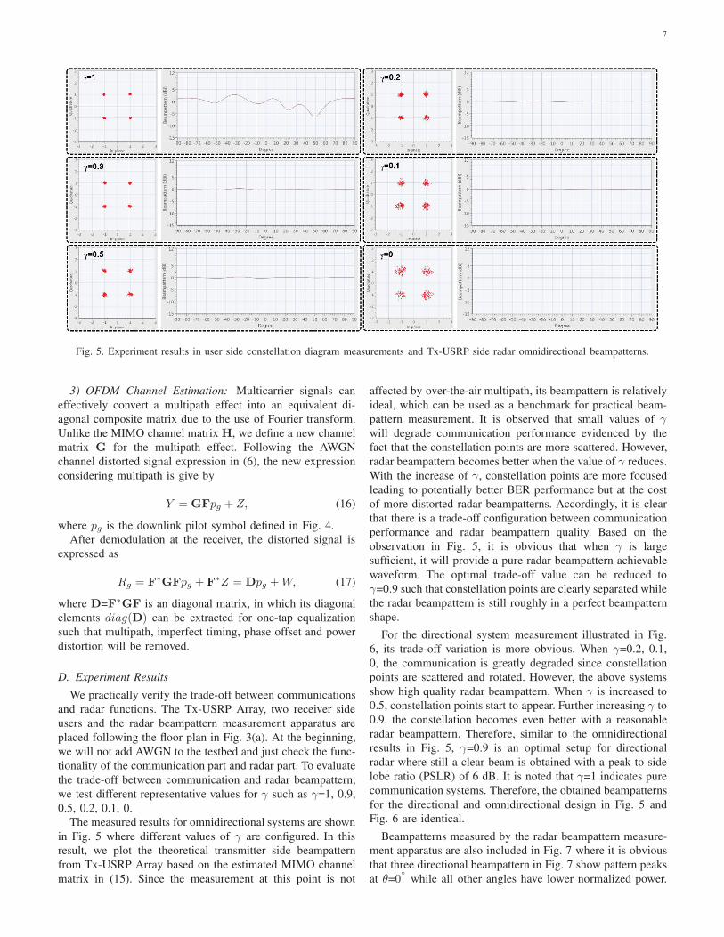
Fig. 5. Experiment results in user side constellation diagram measurements and Tx-USRP side radar omnidirectional beampatterns.
3) OFDM Channel Estimation: Multicarrier signals can
effectively convert a multipath effect into an equivalent di-
agonal composite matrix due to the use of Fourier transform.
Unlike the MIMO channel matrix H, we define a new channel
matrix G for the multipath effect. Following the AWGN
channel distorted signal expression in (6), the new expression
considering multipath is give by
Y = GFpg + Z, (16)
where pg is the downlink pilot symbol defined in Fig. 4.
After demodulation at the receiver, the distorted signal is
expressed as
Rg = F∗GFpg + F
∗Z = Dpg +W, (17)
where D=F∗GF is an diagonal matrix, in which its diagonal
elements diag(D) can be extracted for one-tap equalization
such that multipath, imperfect timing, phase offset and power
distortion will be removed.
D. Experiment Results
We practically verify the trade-off between communications
and radar functions. The Tx-USRP Array, two receiver side
users and the radar beampattern measurement apparatus are
placed following the floor plan in Fig. 3(a). At the beginning,
we will not add AWGN to the testbed and just check the func-
tionality of the communication part and radar part. To evaluate
the trade-off between communication and radar beampattern,
we test different representative values for γ such as γ=1, 0.9,
0.5, 0.2, 0.1, 0.
The measured results for omnidirectional systems are shown
in Fig. 5 where different values of γ are configured. In this
result, we plot the theoretical transmitter side beampattern
from Tx-USRP Array based on the estimated MIMO channel
matrix in (15). Since the measurement at this point is not
affected by over-the-air multipath, its beampattern is relatively
ideal, which can be used as a benchmark for practical beam-
pattern measurement. It is observed that small values of γwill degrade communication performance evidenced by the
fact that the constellation points are more scattered. However,
radar beampattern becomes better when the value of γ reduces.
With the increase of γ, constellation points are more focused
leading to potentially better BER performance but at the cost
of more distorted radar beampatterns. Accordingly, it is clear
that there is a trade-off configuration between communication
performance and radar beampattern quality. Based on the
observation in Fig. 5, it is obvious that when γ is large
sufficient, it will provide a pure radar beampattern achievable
waveform. The optimal trade-off value can be reduced to
γ=0.9 such that constellation points are clearly separated while
the radar beampattern is still roughly in a perfect beampattern
shape.
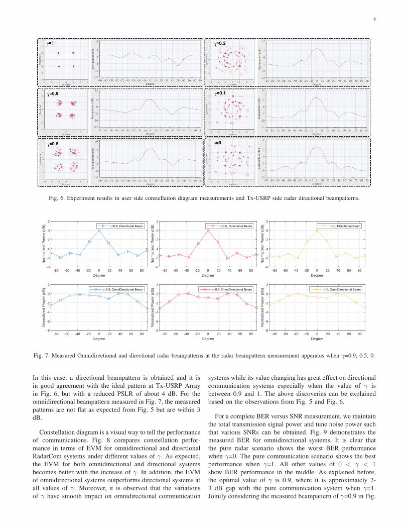
For the directional system measurement illustrated in Fig.
6, its trade-off variation is more obvious. When γ=0.2, 0.1,
0, the communication is greatly degraded since constellation
points are scattered and rotated. However, the above systems
show high quality radar beampattern. When γ is increased to
0.5, constellation points start to appear. Further increasing γ to
0.9, the constellation becomes even better with a reasonable
radar beampattern. Therefore, similar to the omnidirectional
results in Fig. 5, γ=0.9 is an optimal setup for directional
radar where still a clear beam is obtained with a peak to side
lobe ratio (PSLR) of 6 dB. It is noted that γ=1 indicates pure
communication systems. Therefore, the obtained beampatterns
for the directional and omnidirectional design in Fig. 5 and
Fig. 6 are identical.
Beampatterns measured by the radar beampattern measure-
ment apparatus are also included in Fig. 7 where it is obvious
that three directional beampattern in Fig. 7 show pattern peaks
at θ=0◦
while all other angles have lower normalized power.
8
Fig. 6. Experiment results in user side constellation diagram measurements and Tx-USRP side radar directional beampatterns.
-80 -60 -40 -20 0 20 40 60 80
Degree
-8
-6
-4
-2
0
2
Nor
mal
ized
Pow
er (
dB) =0.9, Directional Beam
-80 -60 -40 -20 0 20 40 60 80
Degree
-8
-6
-4
-2
0
2
Nor
mal
ized
Pow
er (
dB) =0.9, OmniDirectional Beam
-80 -60 -40 -20 0 20 40 60 80
Degree
-8
-6
-4
-2
0
2
Nor
mal
ized
Pow
er (
dB) =0.5, Directional Beam
-80 -60 -40 -20 0 20 40 60 80
Degree
-8
-6
-4
-2
0
2
Nor
mal
ized
Pow
er (
dB) =0.5, OmniDirectional Beam
-80 -60 -40 -20 0 20 40 60 80
Degree
-8
-6
-4
-2
0
2
Nor
mal
ized
Pow
er (
dB) =0, Directional Beam
-80 -60 -40 -20 0 20 40 60 80
Degree
-8
-6
-4
-2
0
2
Nor
mal
ized
Pow
er (
dB) =0, OmniDirectional Beam
Fig. 7. Measured Omnidirectional and directional radar beampatterns at the radar beampattern measurement apparatus when γ=0.9, 0.5, 0.
In this case, a directional beampattern is obtained and it is
in good agreement with the ideal pattern at Tx-USRP Array
in Fig. 6, but with a reduced PSLR of about 4 dB. For the
omnidirectional beampattern measured in Fig. 7, the measured
patterns are not flat as expected from Fig. 5 but are within 3
dB.
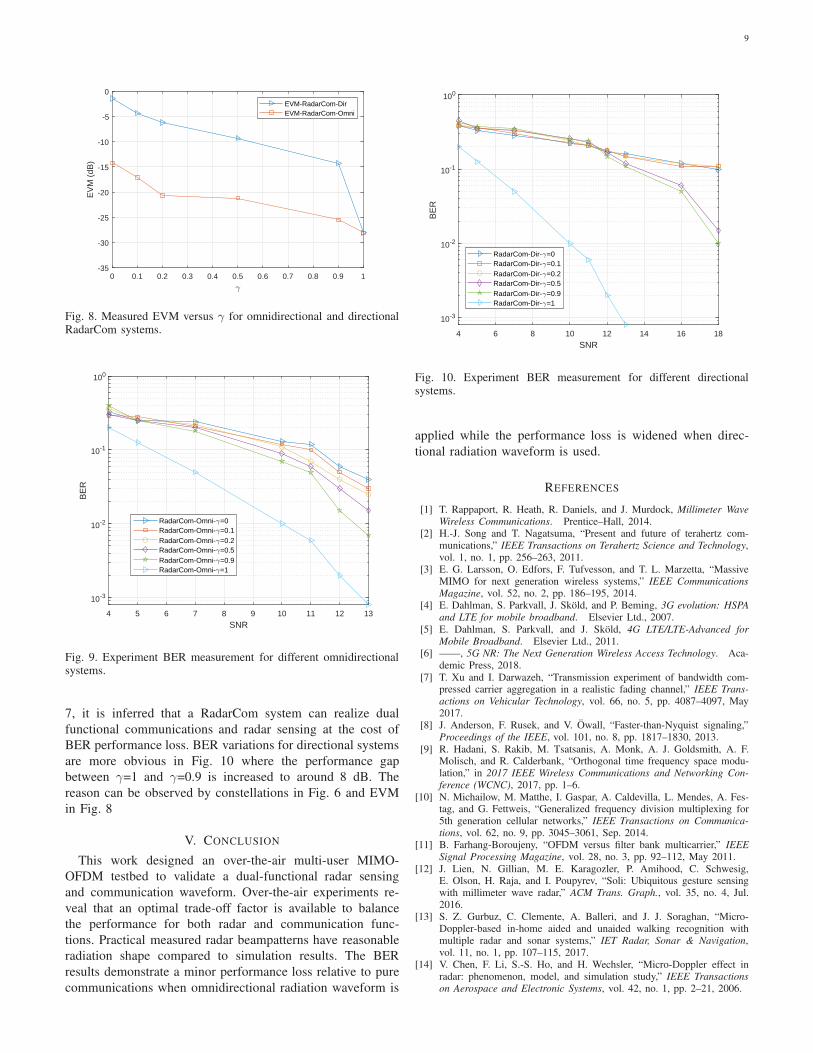
Constellation diagram is a visual way to tell the performance
of communications. Fig. 8 compares constellation perfor-
mance in terms of EVM for omnidirectional and directional
RadarCom systems under different values of γ. As expected,
the EVM for both omnidirectional and directional systems
becomes better with the increase of γ. In addition, the EVM
of omnidirectional systems outperforms directional systems at
all values of γ. Moreover, it is observed that the variations
of γ have smooth impact on omnidirectional communication
systems while its value changing has great effect on directional
communication systems especially when the value of γ is
between 0.9 and 1. The above discoveries can be explained
based on the observations from Fig. 5 and Fig. 6.
For a complete BER versus SNR measurement, we maintain
the total transmission signal power and tune noise power such
that various SNRs can be obtained. Fig. 9 demonstrates the
measured BER for omnidirectional systems. It is clear that
the pure radar scenario shows the worst BER performance
when γ=0. The pure communication scenario shows the best
performance when γ=1. All other values of 0 < γ < 1show BER performance in the middle. As explained before,
the optimal value of γ is 0.9, where it is approximately 2-
3 dB gap with the pure communication system when γ=1.
Jointly considering the measured beampattern of γ=0.9 in Fig.
9
0 0.1 0.2 0.3 0.4 0.5 0.6 0.7 0.8 0.9 1-35
-30
-25
-20
-15
-10
-5
0E
VM
(dB
)
EVM-RadarCom-DirEVM-RadarCom-Omni
Fig. 8. Measured EVM versus γ for omnidirectional and directionalRadarCom systems.
4 5 6 7 8 9 10 11 12 13
SNR
10-3
10-2
10-1
100
BE
R
RadarCom-Omni- =0RadarCom-Omni- =0.1RadarCom-Omni- =0.2RadarCom-Omni- =0.5RadarCom-Omni- =0.9RadarCom-Omni- =1
Fig. 9. Experiment BER measurement for different omnidirectionalsystems.
7, it is inferred that a RadarCom system can realize dual
functional communications and radar sensing at the cost of
BER performance loss. BER variations for directional systems
are more obvious in Fig. 10 where the performance gap
between γ=1 and γ=0.9 is increased to around 8 dB. The
reason can be observed by constellations in Fig. 6 and EVM
in Fig. 8
V. CONCLUSION
This work designed an over-the-air multi-user MIMO-
OFDM testbed to validate a dual-functional radar sensing
and communication waveform. Over-the-air experiments re-
veal that an optimal trade-off factor is available to balance
the performance for both radar and communication func-
tions. Practical measured radar beampatterns have reasonable
radiation shape compared to simulation results. The BER
results demonstrate a minor performance loss relative to pure
communications when omnidirectional radiation waveform is
4 6 8 10 12 14 16 18
SNR
10-3
10-2
10-1
100
BE
R
RadarCom-Dir- =0RadarCom-Dir- =0.1RadarCom-Dir- =0.2RadarCom-Dir- =0.5RadarCom-Dir- =0.9RadarCom-Dir- =1
Fig. 10. Experiment BER measurement for different directionalsystems.
applied while the performance loss is widened when direc-
tional radiation waveform is used.
REFERENCES
[1] T. Rappaport, R. Heath, R. Daniels, and J. Murdock, Millimeter Wave
Wireless Communications. Prentice–Hall, 2014.[2] H.-J. Song and T. Nagatsuma, “Present and future of terahertz com-
munications,” IEEE Transactions on Terahertz Science and Technology,vol. 1, no. 1, pp. 256–263, 2011.
[3] E. G. Larsson, O. Edfors, F. Tufvesson, and T. L. Marzetta, “MassiveMIMO for next generation wireless systems,” IEEE Communications
Magazine, vol. 52, no. 2, pp. 186–195, 2014.[4] E. Dahlman, S. Parkvall, J. Skold, and P. Beming, 3G evolution: HSPA
and LTE for mobile broadband. Elsevier Ltd., 2007.
[5] E. Dahlman, S. Parkvall, and J. Skold, 4G LTE/LTE-Advanced for
Mobile Broadband. Elsevier Ltd., 2011.[6] ——, 5G NR: The Next Generation Wireless Access Technology. Aca-
demic Press, 2018.
[7] T. Xu and I. Darwazeh, “Transmission experiment of bandwidth com-pressed carrier aggregation in a realistic fading channel,” IEEE Trans-
actions on Vehicular Technology, vol. 66, no. 5, pp. 4087–4097, May2017.
[8] J. Anderson, F. Rusek, and V. Owall, “Faster-than-Nyquist signaling,”Proceedings of the IEEE, vol. 101, no. 8, pp. 1817–1830, 2013.
[9] R. Hadani, S. Rakib, M. Tsatsanis, A. Monk, A. J. Goldsmith, A. F.Molisch, and R. Calderbank, “Orthogonal time frequency space modu-lation,” in 2017 IEEE Wireless Communications and Networking Con-
ference (WCNC), 2017, pp. 1–6.
[10] N. Michailow, M. Matthe, I. Gaspar, A. Caldevilla, L. Mendes, A. Fes-tag, and G. Fettweis, “Generalized frequency division multiplexing for5th generation cellular networks,” IEEE Transactions on Communica-
tions, vol. 62, no. 9, pp. 3045–3061, Sep. 2014.[11] B. Farhang-Boroujeny, “OFDM versus filter bank multicarrier,” IEEE
Signal Processing Magazine, vol. 28, no. 3, pp. 92–112, May 2011.
[12] J. Lien, N. Gillian, M. E. Karagozler, P. Amihood, C. Schwesig,E. Olson, H. Raja, and I. Poupyrev, “Soli: Ubiquitous gesture sensingwith millimeter wave radar,” ACM Trans. Graph., vol. 35, no. 4, Jul.2016.
[13] S. Z. Gurbuz, C. Clemente, A. Balleri, and J. J. Soraghan, “Micro-Doppler-based in-home aided and unaided walking recognition withmultiple radar and sonar systems,” IET Radar, Sonar & Navigation,vol. 11, no. 1, pp. 107–115, 2017.
[14] V. Chen, F. Li, S.-S. Ho, and H. Wechsler, “Micro-Doppler effect inradar: phenomenon, model, and simulation study,” IEEE Transactions
on Aerospace and Electronic Systems, vol. 42, no. 1, pp. 2–21, 2006.

10
[15] G. Zhang, H. Li, and F. Wenger, “Object detection and 3D estimationvia an FMCW radar using a fully convolutional network,” ICASSP 2020- 2020 IEEE International Conference on Acoustics, Speech and Signal
Processing (ICASSP), pp. 4487–4491, 2020.[16] Z. Hu, Z. Zeng, K. Wang, W. Feng, J. Zhang, Q. Lu, and X. Kang,
“Design and analysis of a UWB MIMO radar system with miniaturizedVivaldi antenna for through-wall imaging,” Remote Sensing, vol. 11,no. 16, 2019.
[17] F. Adib and D. Katabi, “See through walls with WiFi!” New York,NY, USA: Association for Computing Machinery, 2013.
[18] IEEE 802.11bf Task Group (TG), “Status ofproject IEEE 802.11bf,” 2021. [Online]. Available:https://www.ieee802.org/11/Reports/tgbf update.htm
[19] O. Kaltiokallio, H. Yigitler, R. Jantti, and N. Patwari, “Non-invasiverespiration rate monitoring using a single COTS TX-RX pair,” in IPSN-
14 Proceedings of the 13th International Symposium on Information
Processing in Sensor Networks, 2014, pp. 59–69.[20] N. Patwari, L. Brewer, Q. Tate, O. Kaltiokallio, and M. Bocca,
“Breathfinding: A wireless network that monitors and locates breathingin a home,” IEEE Journal of Selected Topics in Signal Processing, vol. 8,no. 1, pp. 30–42, 2014.
[21] H. Abdelnasser, K. A. Harras, and M. Youssef, “Ubibreathe: A ubiqui-tous non-invasive wifi-based breathing estimator,” 2015.
[22] Z. Yang, P. H. Pathak, Y. Zeng, X. Liran, and P. Mohapatra, “Moni-toring vital signs using millimeter wave.” Association for ComputingMachinery, 2016.
[23] G. Z. Yongsen Ma and S. Wang, “WiFi sensing with channel stateinformation: A survey,” ACM Computing Surveys, vol. 52, no. 3, pp.1–36, 2019.
[24] Q. Song, S. Guo, X. Liu, and Y. Yang, “CSI amplitude fingerprinting-based NB-IoT indoor localization,” IEEE Internet of Things Journal,vol. 5, no. 3, pp. 1494–1504, 2018.
[25] C. Wu, Z. Yang, Z. Zhou, K. Qian, Y. Liu, and M. Liu, “PhaseU:Real-time LOS identification with WiFi,” in 2015 IEEE Conference onComputer Communications (INFOCOM), 2015, pp. 2038–2046.
[26] X. Wang, C. Yang, and S. Mao, “PhaseBeat: Exploiting CSI phasedata for vital sign monitoring with commodity WiFi devices,” in 2017
IEEE 37th International Conference on Distributed Computing Systems(ICDCS), 2017, pp. 1230–1239.
[27] Y. Wang, K. Wu, and L. M. Ni, “WiFall: Device-free fall detection bywireless networks,” IEEE Transactions on Mobile Computing, vol. 16,no. 2, pp. 581–594, 2017.
[28] G. Wang, Y. Zou, Z. Zhou, K. Wu, and L. M. Ni, “We can hear youwith Wi-Fi!” IEEE Transactions on Mobile Computing, vol. 15, no. 11,pp. 2907–2920, 2016.
[29] K. Qian, C. Wu, Z. Yang, Y. Liu, F. He, and T. Xing, “Enablingcontactless detection of moving humans with dynamic speeds usingCSI,” ACM Trans. Embed. Comput. Syst., vol. 17, no. 2, Jan. 2018.
[30] J. Liu, Y. Chen, Y. Wang, X. Chen, J. Cheng, and J. Yang, “Monitoringvital signs and postures during sleep using WiFi signals,” IEEE Internet
of Things Journal, vol. 5, no. 3, pp. 2071–2084, 2018.[31] Q. Zhang, H. Sun, Z. Wei, and Z. Feng, “Sensing and communication
integrated system for autonomous driving vehicles,” in IEEE INFOCOM
2020 - IEEE Conference on Computer Communications Workshops
(INFOCOM WKSHPS), 2020, pp. 1278–1279.[32] P. M. McCormick, S. D. Blunt, and J. G. Metcalf, “Simultaneous radar
and communications emissions from a common aperture, part i: Theory,”in 2017 IEEE Radar Conference (RadarConf), 2017, pp. 1685–1690.
[33] P. M. McCormick, B. Ravenscroft, S. D. Blunt, A. J. Duly, andJ. G. Metcalf, “Simultaneous radar and communication emissions froma common aperture, part ii: Experimentation,” in 2017 IEEE Radar
Conference (RadarConf), 2017, pp. 1697–1702.[34] J. B. Sanson, D. Castanheira, A. Gameiro, and P. P. Monteiro, “Non-
orthogonal multicarrier waveform for radar with communications sys-tems: 24 GHz GFDM RadCom,” IEEE Access, vol. 7, pp. 128 694–128 705, 2019.
[35] J. Wang, X.-D. Liang, L.-Y. Chen, L.-N. Wang, and K. Li, “Firstdemonstration of joint wireless communication and high-resolution SARimaging using airborne MIMO radar system,” IEEE Transactions on
Geoscience and Remote Sensing, vol. 57, no. 9, pp. 6619–6632, 2019.[36] C. Baquero Barneto, T. Riihonen, M. Turunen, L. Anttila, M. Fleischer,
K. Stadius, J. Ryynanen, and M. Valkama, “Full-duplex OFDM radarwith LTE and 5G NR waveforms: Challenges, solutions, and mea-surements,” IEEE Transactions on Microwave Theory and Techniques,vol. 67, no. 10, pp. 4042–4054, 2019.
[37] P. Kumari, A. Mezghani, and R. W. Heath, “JCR70: A low-complexitymillimeter-wave proof-of-concept platform for a fully-digital SIMO joint
communication-radar,” IEEE Open Journal of Vehicular Technology,vol. 2, pp. 218–234, 2021.
[38] T. Huang, N. Shlezinger, X. Xu, Y. Liu, and Y. C. Eldar, “Majorcom:A dual-function radar communication system using index modulation,”IEEE Transactions on Signal Processing, vol. 68, pp. 3423–3438, 2020.
[39] F. Liu, L. Zhou, C. Masouros, A. Li, W. Luo, and A. Petropulu, “To-ward dual-functional radar-communication systems: Optimal waveformdesign,” IEEE Transactions on Signal Processing, vol. 66, no. 16, pp.4264–4279, 2018.
[40] T. Xu, C. Masouros, and I. Darwazeh, “Waveform and space precodingfor next generation downlink narrowband IoT,” IEEE Internet of Things
Journal, vol. 6, no. 3, pp. 5097–5107, Jun. 2019.[41] D. R. Fuhrmann and G. San Antonio, “Transmit beamforming for MIMO
radar systems using signal cross-correlation,” IEEE Transactions on
Aerospace and Electronic Systems, vol. 44, no. 1, pp. 171–186, 2008.[42] P. Stoica, J. Li, and Y. Xie, “On probing signal design for MIMO radar,”
IEEE Transactions on Signal Processing, vol. 55, no. 8, pp. 4151–4161,2007.
[43] Vaunix, “LPS-402 programmable phase shifter,” https://vaunix.com/lps-402-digital-phase-shifter/, May 2019.
[44] T. Xu, C. Masouros, and I. Darwazeh, “Design and prototyping of hybridanalogue digital multiuser MIMO beamforming for non-orthogonalsignals,” IEEE Internet of Things Journal, vol. 7, no. 3, pp. 1872–1883,Mar. 2020.
[45] C. A. Balanis. John Wiley & Sons, 2016. [Online]. Available:https://app.knovel.com/hotlink/toc/id:kpATADE01N/antenna-theory-analysis/antenna-theory-analysis
Related Documents