† † ‡ † ‡

Welcome message from author
This document is posted to help you gain knowledge. Please leave a comment to let me know what you think about it! Share it to your friends and learn new things together.
Transcript

An equilibrated macro-element for nonlinear analysis of
masonry structures
Daniela Addessi†, Alessandro Mastrandrea† and Elio Sacco‡
† Dipartimento di Ingegneria Strutturale e Geotecnica,
Università di Roma �Sapienza�, Via Eudossiana 18, 00184 Roma, Italy
‡ Dipartimento di Ingegneria Civile e Meccanica,
Università di Cassino e del Lazio Meridionale, Via G. Di Biasio 43, 03043 Cassino, Italy
Abstract
A new macro-element based on the equivalent frame approach is presented to analyze the
nonlinear in-plane structural response of masonry panels under lateral loadings. A nonlinear
elastic response is assumed for the masonry material, limiting the focus to the case of mono-
tonic loading condition, typical of push-over analysis. The sectional response of the beam
is determined performing analytical integration, without resorting to a �ber approach. A
two-node force-based (FB) beam �nite element (FE) is formulated, where the resultant stress
components are exactly interpolated along the beam axis. The beam FE is composed of a
central �exible element characterized by a no-tension constitutive relationship and a lumped
nonlinear shear hinge arranged in series. Hence, it is possible to capture the main �exural
and shear nonlinear mechanisms typical of a masonry panel response. An e�cient solution
Preprint of the paper:
D. Addessi, A. Mastrandrea, E. Sacco, An equilibrated macro-element for nonlin-ear analysis of masonry structures. Engineering Structures 70 (2014) 82-93 (DOI10.1016/j.engstruct.2014.03.034).
1

algorithm is developed based on a consistent element state determination procedure. Some
applications on simple panels and on experimental walls with openings are presented, showing
a very satisfactory agreement between the numerical and the experimental results, both in
terms of global push-over curves and local distributions of damaging paths.
Keywords: Masonry, force-based beam element, macro-element, spread inelasticity, nonlin-
ear analysis.
1 Introduction
Masonry structures represent a signi�cant part of the architectural and cultural heritage of
historic centers. Thus, the evaluation of the stability of masonry structures is important,
when considering the preservation of our cultural heritage and safe-guarding people's lives.
The development of accurate stress analyses is essential to assess the safety state, decide the
retro�t interventions and, eventually, design any required strengthening systems.
Masonry is a heterogeneous material characterized by nonlinear response, even for low de-
formation levels. For this reason the structural analysis of masonry elements is not an easy
task. Nonlinear anisotropic constitutive laws are required and behavior in tension and in
compression is markedly di�erent. Much focus is currently given to the formulation of non-
linear constitutive relationships for masonry and a large number of models are now available
[2, 3, 4, 1, 5]. The most natural approach for describing the mechanical behavior of the ma-
sonry structural elements is the adoption of continuous material models. In this framework,
a wide variety of continuous 2D and 3D nonlinear models have been proposed. These in-
clude complex nonlinear mechanisms such as friction-plasticity, cohesion, crushing, damage
and so on. Some models are implemented in �nite element (FE) commercial codes. However,
nonlinear FE analysis of masonry structures [6], modeled as 2D or 3D problems, is quite
complex. There are at least two reasons for this: the computational e�ort and the di�culty
in identifying the model parameters. In fact, constitutive models accurately describing the
stress-strain response of the masonry are governed by several material parameters. These are
2

not easy to determine for actual buildings, as they require speci�c laboratory tests that can-
not be performed in real applications. Alternatively, homogenization techniques have been
proposed to derive the stress-strain relationships of the masonry, regarded as a composite
material made of brick (natural or arti�cial) and mortar [7, 8, 9, 10]. Even this challenging
approach presents some di�culties in practical applications, connected to the great variability
of the masonry texture (often irregular) and the variety of the brick typology. Moreover, it
requires very high computational e�orts. The computational cost is even greater because of
the need for regularization techniques, such as nonlocal procedures, to overcome localization
problems arising when constitutive laws with strain softening are adopted.
Several simpli�ed techniques have been proposed to perform structural analyses capable of
evaluating the overall nonlinear response of masonry constructions and of capturing the main
features of their structural response. Macro-element models have been successfully proposed
to perform nonlinear push-over analyses. These describe damage, crushing, frictional sliding
mechanisms in pre-established regions of the structural elements on the basis of simpli�ed
modeling assumptions and more or less sophisticated nonlinear material constitutive laws.
Generally, these models allow incremental nonlinear collapse analysis of individual walls or
of overall 3D buildings with horizontal �oors. Recent observations on earthquake induced
damage to masonry constructions con�rm that the mechanisms of the walls can be subdivided
into in-plane and out-of-plane, provided that fabric mechanisms are prevented [11].
Macro-elements based on the 2D modeling of the masonry panels have been proposed in
[12], where a speci�c distribution of the stress �eld is assumed inside the masonry panel
and a no-tension constitutive law is used. A simpli�ed formulation has been presented in
[13], where a macro-element was proposed, characterized by eight displacement degrees of
freedom, six related to the end nodes and two representing internal variables. Overturning,
damage and frictional sliding mechanisms are taken into account. Chen et al. [14] proposed
a macro-element including an axial spring, three shear springs and two rotational springs to
simulate the axial, bed joint sliding, diagonal tension and rocking/toe crushing failure modes,
experimentally observed in the masonry piers. Equivalent frame models have been proposed
3

by a number of authors, which have been extensively used for practical analysis of common
masonry structures [18, 19, 16, 17, 15]. In particular, for the study of building systems
composed of load bearing walls, an equivalent frame model made of beam FEs is adopted,
where each wall with openings is decomposed into an assemblage of piers and spandrels,
properly connected by means of rigid elements.
The FE formulations of the macro-elements available are mainly based on the classical dis-
placement approach, which could be a�ected by the well-known shear locking problems. More-
over, in the presence of nonlinear constitutive behavior, where non smooth and localized dis-
tributions of deformations in the structural element are expected, either �ne and non uniform
discretizations or enriched displacement formulations [17] are needed, to satisfactorily describe
the mechanical response. It has been demonstrated [20, 21, 22] that beam elements derived
by the force-based (FB) approach, interpolating the stress �elds along the element, are com-
putationally more e�cient with respect to the displacement-based formulations, especially in
the presence of nonlinear behavior, both constitutive and geometric. To be noted is that the
numerical solution in this case is only a�ected by the error related to the adopted integration
rule. Hence, it is possible to adopt coarser meshes for the structural discretization compared
with the displacement-based approach.
In this paper, a new FB macro-element for the analysis of the nonlinear response of masonry
buildings, modeled on the basis of the equivalent frame approach, is proposed. To describe
the low tensile and the limited compressive strength of the masonry and the failure due to
shear mechanisms, a 2-node FE, with a spread nonlinear constitutive behavior including a
lumped nonlinear shear hinge, is adopted. The modeling techniques, based only on the use
of lumped hinges, to account for all the nonlinear e�ects in the masonry elements appear,
from a mechanical point of view, less natural than the continuum approach. Furthermore,
the selection of the mechanical parameters governing the nonlinear response of the hinges
subjected to axial force and bending moment, as well as their e�ective lengths, is not an easy
task. However, when a spread nonlinear constitutive model is adopted, it su�ces to select the
material parameters and, thus, the nonlinear nonuniform response of the structural element,
4

characterized by the coupling of the axial and bending e�ects, is correctly determined.
The beam FE, formulated on the basis of the Timoshenko theory, consists of a central �exible
element with a nonlinear constitutive behavior and a nonlinear shear hinge arranged in series
with the �exible element, as well as two end rigid o�sets. Regarding the computational
aspects, a nonlinear solution algorithm based on a consistent element state determination
procedure is developed. The proposed FB macro-element is implemented in the FE code
FEAP [23].
The paper is organized as follows: in Section 2 the nonlinear no-tension constitutive relation-
ship adopted for the masonry is described; in Section 3 the formulation of the overall FE,
composed of the �exible central element, the lumped shear hinge and the end rigid o�sets is
presented and the constitutive relationship adopted to model the nonlinear response of the
shear hinge is introduced; in Section 4 the solution algorithm is illustrated; �nally, in Section
5 some numerical applications on simple panels and on full-scale experimental masonry walls
are presented, by comparing results from the proposed FE with experimental outcomes and
with the results from di�erent numerical formulations.
2 Constitutive model for masonry
Since masonry material is characterized by a negligible tensile strength, the no-tension consti-
tutive assumption suitably describes its mechanical response. To assess the push-over response
curves of masonry buildings, the nonlinear constitutive law for monotonic loading conditions
presented in [24] and [17] is adopted, taking into account the nonlinear mechanisms related
to the fracture in tension and to the limited strength in compression typical of the masonry.
To account for the shear deformations, the Timoshenko beam model is adopted. The shear
constitutive response of the beam is considered as linear elastic in the cross-section portion
undergoing a compressive strain state. Thus, if the entire section is compressed, a linear
elastic shear response is recovered and the shear failure mechanism (i.e. the sliding) is not
activated. To account for the possible nonlinear shear mechanisms, when the section is fully or
5

partially compressed, a lumped shear hinge characterized by nonlinear response in introduced
in the beam. The equations governing the constitutive response of the masonry are expressed
as:
σ = E(ε− εi
)τ = G
(γ − γi
) (1)
where σ is the normal stress, τ the shear stress, ε the total normal strain and γ the total shear
strain, while εi is the inelastic normal strain due to the fracture process related to the assumed
no-tensile strength and to the limited compressive strength; γi is the inelastic shear strain
occurring in the presence of fracture strain. Moreover, E and G are the masonry Young's and
shear moduli, respectively. Three cases can be distinguished:
ε > 0 εl < ε ≤ 0 ε ≤ εl
εi = ε εi = hε2
4εyεi = ε− εy
γi = γ γi = 0 γi = 0
(2)
where εy = σy/E, with σy denoting the normal compressive strength, εl is the normal strain
limit value and h a model parameter. When h = 0, a linear elastic response is obtained for
ε ≥ εy and in this case εl = εy, otherwise h = 1 is assumed and εl = 2εy. In Fig. 1 the
stress-strain laws are depicted denoting with M1 the curve corresponding to h = 0 and M2
the case h = 1. The strain ultimate value εu is also shown denoting the limit strain which,
when reached, causes the interruption of the analysis.
3 Beam �nite element formulation
The formulation of the frame element presented assumes the Timoshenko kinematic model
with a geometrically linear behavior. The overall FE is composed of a �exible central element
with a distributed nonlinear constitutive behavior, a lumped nonlinear shear hinge and two
end rigid o�sets.
6

3.1 Flexible central element
The element forces and displacements are expressed in the basic local reference system by the
following vectors (Fig. 2(a)):
Q = {Q1 Q2 Q3}T , q = {q1 q2 q3}T (3)
where Q1 and Q2 are the bending moments at the end nodes i and j and Q3 is the axial
force. Similarly, q1 and q2 are the nodal deformational rotations and q3 is the axial elongation
expressed in the basic system. Both Q and q are related to the six component vectors P and
p (Fig. 2(b)), containing the nodal forces and displacements expressed in the global reference
system, by the following relations:
q = BRp , P = RTBTQ (4)
where the operator R is an orthogonal rotation matrix projecting P and p in the local
reference system, while B is a kinematic operator eliminating the rigid modes from the local
displacement vector Rp. In particular, it results:
R =
cosα sinα 0 0 0 0
− sinα cosα 0 0 0 0
0 0 1 0 0 0
0 0 0 cosα sinα 0
0 0 0 − sinα cosα 0
0 0 0 0 0 1
, B =
0 1/L 1 0 −1/L 0
0 1/L 0 0 −1/L 1
−1 0 0 1 0 0
α being the angle between the local and global axes, x and X, and L denoting the element
length.
The section stress vector, containing the stress resultants in the beam cross-section and the
7

generalized deformation vector, are de�ned as:
S (x) = {N (x) T (x) M (x)}T , d (x) = {ε0 (x) δ (x) χ (x)}T (5)
where N(x) is the axial force, T (x) the shear force and M(x) the bending moment, while
ε0 (x) is the axial deformation along the reference axis x, δ (x) the shear deformation and
χ (x) the curvature.
According to the FB formulation the section stress �eld is expressed by a polynomial inter-
polation:
S(x) = b(x)Q + Sq(x) (6)
where the equilibrium matrix b(x) is expressed as:
b (x) =
0 0 1
1/L 1/L 0
x/L− 1 x/L 0
and the vector Sq = {Nq (x) Tq (x) Mq (x)}T contains the section stresses due to the external
loads, distributed along the reference axis. Disregarding the distributed loads along the
element, i.e. assuming Sq = 0, constant axial and shear forces and linear variation of the
bending moment along the element exactly describe the stress �elds in the element, which
satisfy equilibrium.
Vectors d (x) and S (x) are related by means of a generalized constitutive law, which in a FB
approach involves the section �exibility matrix f (x).
The equation governing the cross-section constitutive response is obtained by integrating the
masonry material constitutive law (Eq. 2) in the cross-section, A, where in the most general
case three portions are distinguished: the no-reagent part subjected to zero stress (ε > 0);
the compressed part, Ae, subjected to normal stress monotonically increasing as the distance
from the neutral axis grows (εl < ε ≤ 0); the compressed part, Al, subjected to a uniform
8

normal stress (ε ≤ εl). Two di�erent axes may be de�ned for the cross-section: the neutral
axis yn = −ε0/χ and the inelastic axis yi = (εy − ε0) /χ. The resulting generalized section
constitutive relationship can be written in the following form:
S =
´A σ dA´A τ dA´
A y σ dA
= k d− Sl (7)
where k is the section sti�ness matrix, which results as:
k =
EAel 0 ESel
0 κGAel 0
ESel 0 EIel
(8)
being:
Ael =
ˆAe∪Al
dA Sel =
ˆAe∪Al
y dA Iel =
ˆAe∪Al
y2 dA (9)
and κ the shear correction factor.
Moreover, the inelastic stress vector Sl is de�ned as:
Sl =
Nl
Tl
Ml
=
E [Al (ε0 − εy) + Slχ] + h
σi4ε2i
(Aeε
20 + 2Seε0χ+ Ieχ
2)
0
E [Sl (ε0 − εy) + Ilχ] + hσy4ε2y
(Seε
20 + 2Ieε0χ+ Jeχ
2)
(10)
where Se and Ie are the �rst and second order moments of the cross-section portion Ae, while
Sl and Il are the same quantities for the cross-section inelastic portion Al and Je is the third-
order moment of Ae. Consistently with the FB approach, the inverse form of the constitutive
relationship in Eq. 7 is required, resulting as:
d = f(S + Sl
)(11)
9

with f = k−1 denoting the section �exibility matrix. Note that the matrices k and f are not
constant along the beam axis, as they depend on the values of the stress resultants acting
in each cross-section of the beam. Furthermore, the matrix k implicitly accounts for the no-
tension response of the masonry material. In fact, it is obtained by performing the integrals
in Eq. 9 only in the compressed region of the section. As a consequence, when the section is
subjected to a tensile state, the matrix k vanishes.
By applying the principle of the virtual work, the relation between the vectors of the nodal
displacements, q, and forces, Q, is derived in the form:
q = F Q + qq + ql (12)
where the �exibility matrix F of the central element is introduced, de�ned as:
F =
L
0
bT (x) f (x) b (x) dx =
AelL
3EZel+
1
LGκAel− AelL
6EZel+
1
LGκAel
SelL
2EZel
− AelL
6EZel+
1
LGκAep
AelL
3EZel+
1
LGκAel− SepL
2EZelSelL
2EZel− SelL
2EZel
IelL
EZel
(13)
being Zel = AelIel − S2el. The equivalent nodal displacement vectors, qq and ql, taking into
account the distributed loads and inelastic stresses, respectively, are de�ned as:
qq =
L
0
bT (x) f (x) Sq (x) dx ; ql =
L
0
bT (x) f (x) Sl (x) dx (14)
3.2 Nonlinear shear hinge
To model the shear failure mechanisms typical of masonry buildings subjected to seismic like
loading conditions, a shear hinge is introduced into the beam FE formulation. The nonlinear
behavior of the shear hinge expressed in terms of the slip, s, and the shear force, T , is written
10

as:
T = Ksh (s− sp) (15)
with sp denoting the inelastic slip and Ksh the shear hinge sti�ness coe�cient. The value
assumed by the inelastic slip, sp, is ruled by the following equations:
sp = 0 if |s| < sy
sp =
(1 +
H
Ksh
)(|s| − sy) sign (s) if sy ≤ |s| < su
sp =
(|s| − Ksh +H
Kshsy +
H
Kshsu
)sign (s) if |s| ≥ su
(16)
where sy = Ty/Ksh, being Ty the shear strength evaluated according to the Italian seismic
guidelines [25] (see Appendix A), H ≤ 0 is the slope of the softening branch and su the
relative transversal displacement, corresponding to the end of the softening branch, as shown
in Fig. 3. Note that, by adopting H = 0, a horizontal post-peak branch is recovered.
To introduce the shear hinge contribution into the element �exibility matrix, assuming that
it is arranged in series with the FE, the constitutive relationship in Eq. 15 is expressed in
function of the nodal displacements and forces as:
qsh L = FshQ1 +Q2
L(17)
where qsh is the rotational contribution of the nonlinear shear hinge to the nodal rotation
parameters q1 and q2. The quantity Fsh is the secant �exibility coe�cient of the shear hinge,
so that its contribution to the overall element �exibility results as Fsh/L2. As a consequence
of the adopted equilibrated formulation for the beam, which assumes a uniform distribution
of the shear stress, the formation of the shear hinge is not concentrated in a speci�c point
of the beam. Thus, when the computed shear stress is greater then the shear strength, the
nonlinear hinge is activated and the value of the shear stress along the entire beam is de�nitely
governed by the nonlinear constitutive law in Eqs. 15 and 16.
11

3.3 Rigid o�sets
When the equivalent frame modeling procedure is used to describe the seismic response of
masonry walls, subdivided into piers and spandrels modeled as beam FEs, the regions of the
masonry walls where these interact must be reproduced. Hence, rigid o�sets are introduced
in the FE formulation. In particular, the presence of rigid o�sets aligned with the global
reference system are considered, as illustrated in Fig. 4. By denoting with P the nodal force
vector at the end nodes of the rigid o�sets, the following relation holds:
P =BTR P (18)
with:
BTR =
BTRi 0
0 BTRj
where:
BTRi =
1 0 0
0 1 0
−lY i lXi 1
BTRj =
1 0 0
0 1 0
lY j −lXj 1
and 0 denotes the 3x3 null matrix; lXi(j) and lY i(j) represent the horizontal and vertical rigid
o�set lengths at the end i(j) of the FE, respectively. Dolce's formula [29] is used to assess
the rigid o�set length of the piers. The clear length is assumed as the �exible region of the
spandrels.
By exploiting the virtual work equivalence, the transformation rule for the nodal displacement
degrees of freedom is deduced as:
p =BR p (19)
3.4 Overall frame FE
Since the global solution procedure is based on the displacement method, the element sti�ness
matrix K has to be computed and the element nodal forces P, both de�ned below, have to
12

be determined to evaluate the global residual vector. By introducing Eq. 4 into Eq. 18, it
results:
P = BTRRTBTQ (20)
Then, by substituting the expression of Q derived by Eq. 12, after introducing the shear
hinge contribution, it is obtained:
P = BTRRTBT F−1 (q− qq − ql) = Kp + P0 (21)
where Eqs. 4 and 19 have been exploited. The resulting overall element sti�ness matrix
K = BTRRTBT F−1BRBR involves the inverse of the �exibility matrix including the shear
hinge contribution, i.e.:
F =
AelL
3EZel+
1
LGκAel+Fsh
L2− AelL
6EZel+
1
LGκAel+Fsh
L2
SelL
2EZel
− AelL
6EZel+
1
LGκAep+Fsh
L2
AelL
3EZel+
1
LGκAel+Fsh
L2− SepL
2EZelSelL
2EZel− SelL
2EZel
IelL
EZel
(22)
The equivalent nodal force vector P0 takes into account the contribution of the distributed
loads and of the inelastic strains and is de�ned as:
P0 = −BTRRTBT F−1 (qq + ql) (23)
4 Solution algorithm
The numerical solution of the global incremental nonlinear equilibrium equations, governing
the response of the 2D frame model, follows a classical step-by-step method and a standard
iterative Newton-Raphson algorithm. The fomulated FB FE and the developed solution
algorithm are implemented in the numerical code FEAP [23], used to perform all the numerical
analyses. The assembling procedure of the global sti�ness matrix and residual vector is
13

performed by FEAP, which requires, at the element level, the computation of the element
sti�ness matrix K and the structural reaction force vector P. The methodology developed for
the element state determination is schematically illustrated in Table 1. Note that, in the case
of the presented FB approach, the element state determination procedure is more complex
than for the classical displacement-based formulation and will be presented in some details
following a procedure similar to that proposed in [20, 21].
Hereafter, the superscript ′k′ denotes the value of the variables at the current Newton-Raphson
iteration. After evaluating the element forces Qk on the basis of the current element displace-
ments qk and the element �exibility matrix at the previous iteration Fk−1, the equilibrated
section stresses Sk are computed at each Gauss integration point. The section residual stress
Sk−1, evaluated at the previous iteration and de�ned below, is added. Then, the section defor-
mation dk is updated using the section �exibility matrix fk−1 at the previous iteration. The
constitutive response is evaluated at each Gauss point, computing the new section sti�ness
matrix kk (Eq. 8), the inelastic stress vector Skl (Eq. 10) and, �nally, the section stress vector
Sk (Eq. 7). On the basis of the section �exibility fk, obtained by inverting kk, the element
�exibility matrix Fk is updated. A section deformation residual dk is then determined, based
on the di�erence between the equilibrated section stress Sk and the value obtained by the
constitutive law Sk. This residual is transformed into the element deformation residual rk
by integrating it over the element length, i.e. by summing the contributions evaluated in the
Gauss points selected for the integration over the element, each of which are multiplied by the
transpose of the equilibrium matrix b. By pre-multiplying rk by the element sti�ness(Fk)−1
,
a residual on the element structural reaction forces is calculated, which is used to compute
an updated Qk. Then, the residual section stress Sk can be updated at each Gauss point, by
subtracting from the equilibrated part bQk the stress vector Sk, calculated by means of the
constitutive law (Eq. 7). After which, the determination of the constitutive response of the
shear hinge is performed. On the basis of the current equilibrated shear(Qk
1 +Qk2
)/L and
the previous secant �exibility F k−1sh , the shear hinge deformation, sk, is updated. Then, the
inelastic slip skp (Eq. 16) is evaluated and the constitutive relationship in Eq. 15 is solved.
14

Therefore, the new hinge secant �exibility, F ksh, and the shear, T k, are calculated.
On the basis of the hinge �exibility coe�cient F ksh and the �exibility matrix Fk, the current
�exibility matrix of the resulting element, Fk, is updated. As for the resulting element residual
vector, the deformation residual of the hinge, T k, is determined, based on the di�erence
between the equilibrated shear(Qk
1 +Qk2
)/L and the value obtained by the constitutive law
T k. This hinge deformation residual is added to the element deformation residual rk, evaluated
for the �exible element, by summing the contribution of the shear hinge at each nodal rotation.
By pre-multiplying the resulting rk by the element sti�ness(Fk)−1
, a residual on the element
structural reaction forces is calculated, which is used to compute an updated Qk. Finally,
to take into account the presence of the rigid o�sets and the rotation from the local to the
global reference system, the transformations in Eqs. 20 and 21 are performed. The numerical
integrations along the beam axis are performed using at least three Gauss integration points.
Both the updated Kk and Pk are passed to the global code FEAP for the assembling and
solution procedures; as the Newton-Raphson global iterations proceed, the local deformation
residuals Sk and T k tend to reduce to zero.
5 Numerical Applications
Some examples are presented regarding single panels and experimental prototypes. The nu-
merical results are compared both with the experimental outcomes and those obtained using
di�erent modeling procedures.
5.1 Three experimental panels
To validate the proposed FE numerical model, three simple panels are analyzed and their
geometry and boundary conditions are shown in Fig. 5. The �rst is the unreinforced panel
described in [26], where a micromechanical modeling approach is presented, proposing an
interface model with damage and plasticity for the mortar joints. The adopted geometrical and
15

mechanical parameters, also reported in [31], are shown in Table 2. The panel is subjected to a
constant vertical load P = 311 kN and to a monotonically increasing horizontal displacement
u applied at the top. A single FE is used to model the panel, with the bottom node totally
restrained. The top node is free during the application of the vertical load, then its horizontal
degree of freedom is restrained, to perform the analysis under displacement control. In Fig. 6
the nonlinear response curves obtained by adopting the proposed equilibrated macro-element
(M-E) (solid lines) and the macro-element proposed in [15] (dashed line) are reported and
compared with the curve (triangle symbols) numerically obtained by the micromechanical
approach presented in [26]. The numerical curve obtained by [31] is also plotted (large dashed
line). In particular, referring to the formulation proposed here, two di�erent curves are shown
and evaluated by exploiting the masonry constitutive law M1 (solid thick curve) and M2
(solid thin curve). No relevant di�erences emerge between the two constitutive laws, so that
the M1 bi-linear model is employed. Note that a very good agreement is obtained with the
outcomes from both the micromechanical model [26] and the simpli�ed formulations presented
in [31]. A better match than the formulation proposed in [15] is observed, due to the adoption
of a distributed nonlinear masonry constitutive model instead of a lumped hinge formulation.
The �exural failure mechanism resulting from the detailed micromechanical FE analysis is
well reproduced by the simpli�ed formulation presented, but with a considerable reduction
in the computational e�ort. Instead, as a result of both the simpli�ed and micromechanical
analyses, the shear nonlinear hinge is not activated.
The second example concerns two masonry panels tested at the Joint Research Center of Ispra
[27], characterized by a di�erent ratio L/b: a slender (L/b = 2) and a squat (L/b = 1.35) panel.
The adopted geometrical and mechanical parameters deduced from the experimental tests [28]
are reported in Table 2. Both panels are subjected to a constant vertical load P = 150 kN and
to a monotonically increasing horizontal displacement u applied at the top. In this case, too,
a single FE is used to model the panels, with no rigid o�sets. The beam element is assumed as
clamped at the base with additional restraints on the top node a�ecting horizontal direction
and rotation. The push-over response curves are reported in Fig. 7 (slender panel) and in
16

Fig. 8 (squat panel) in terms of base shear force versus top displacement. In both �gures the
solid curve represents the results obtained by adopting the proposed macro-element (M-E 1);
it is compared with the experimental curve (triangle symbols) and with the results obtained
with the macro-element proposed in [15] (dashed curve). As expected, the di�erent geometry
of the panels in�uences their behavior. In fact, a rocking mechanism drives the collapse of
the slender panel due to the �exural failure, while shear failure appears in the squat panel,
where the diagonal cracking failure prevails. Note that the model adopted for the shear hinge
reproduces the softening behavior experimentally observed after the peak load. Here, too, it
may be observed that the proposed model provides results in very good agreement with the
experimental ones. Furthermore, in Figs. 9, 10 and 11 the in�uence of the variation of some
relevant mechanical parameters on the numerical push-over curves is shown. In particular, in
Fig. 9 the push-over response curve in the case of the slender panel is reported for a wide
range of the normal compressive strength σy = 2.2, 4.2, 6.2, 8.2 MPa. It emerges that the
value assumed for σy does not signi�cantly in�uence the global response, since the rocking
mechanism due to the �exural collapse implies that only a very small portion of the section
is still resistant. In Figs. 10 and 11 the push-over curves related to the squat panel are
shown, varying the parameters governing the nonlinear shear hinge response. In Fig. 10
the variation of the masonry mean shear strength fv0 = 0.137, 0.153, 0.169 MPa is analyzed,
while in Fig. 11 the in�uence of the softening parameter ratio H/Ksh = −0.93,−0.96,−0.99
is investigated. In both cases, the shape of the global response curves is a�ected. However,
the same shear collapse mechanism is activated with little variation of the resulting shear
strength and post-peak slope.
5.2 Pavia's test
The full-scale masonry two-storey building prototype tested at Pavia University has been
extensively studied [3, 18, 32, 17, 15]. Here, the unreinforced door wall D (Fig. 12(a)) and
window wall B (Fig. 13(a)) are analyzed. Two distributed vertical loads, whose resultant
values are P1 = 248.4 kN and P2 = 263.8 kN , are applied at the �rst and second �oor levels,
17

respectively. Then, the walls are subjected to increasing lateral forces, which are applied at the
�oor levels, keeping a 1:1 ratio between the forces at the �rst and second �oor. The mechanical
parameters adopted for the piers and the spandrels are reported in Table 3, deduced from the
relevant literature, where the same experimental walls were numerically analyzed [32]. As for
the shear hinges, the shear strength in each pier and spandrel is evaluated by Eq.26, according
to the experimental shear damaging distributions that show diagonal cracking mechanisms.
The value of the parameter sy = Ty/Ksh in each FE depends on the value of the shear hinge
elastic sti�ness coe�cient Ksh, assumed equal to the initial shear sti�ness coe�cient of the
FE.
The wall thickness t is equal to 0.25m. The piers and the spandrels are modeled by the
proposed beam FE. To reproduce the rigid plane constraint, due to the presence of sti� steel
beams at each �oor, the horizontal displacements of the nodes at the �oors are linked so
as to be equal. The distributed vertical loads p1 and p2 are applied at the �oor nodes as
concentrated vertical forces. With regard to the lateral horizontal forces, F , these are applied
with a 1:1 ratio at the �oor levels, by means of a system of sti� trusses and beams. A horizontal
displacement is applied to the node where the two sti� beams are connected, thus permitting
the two equal forces at the �oor levels to be transferred and a displacement-controlled analysis
performed. The adopted FE models are reported in Fig. 12(b) for wall D and in Fig. 13(b)
for wall B.
5.2.1 Wall D
In Fig. 14 the push-over curves referring to the analysis of the door wall D are reported, de-
picting the total base shear force versus the horizontal displacement measured at the second
�oor. The curve numerically obtained by using the proposed macro-element (M-E 1) (solid
line) is compared with the experimental one (triangle symbols) [3] and with the curve eval-
uated by adopting the macro-element presented in [15] (dashed line). The results computed
by means of both the simpli�ed macro-element models show satisfactory agreement with the
experimental curve, although the proposed macro-element gives a more satisfactory match.
18

There is a less than 5% di�erence in the �nal value of the total base shear force evaluated
with the two numerical models.
In Figs. 15 and 16 the shear and axial stresses, respectively, versus the top displacement,
are reported at the base of the three piers, together with the total base value. As expected,
the shear values are higher in the middle pier (Pier M), where the formation of a shear hinge
also appears, as can be seen in Fig. 17. The axial stress distribution highlights the loading
process of the right pier (Pier R) and the simultaneous unloading of the left pier (Pier L),
due to their location with respect to the horizontal imposed displacement.
In Fig. 17 the trust curves in each pier and spandrel, as well as the distribution of the �exural
and shear hinges at three relevant loading steps, are reported: Fig. 17(a) corresponds to the
top displacement u = 3mm , Fig. 17(b) to u = 8 mm and Fig. 17(c) to u = 18mm.
Note that, initially, the two shear hinges in the spandrels at the �rst �oor are formed, after
which a shear hinge in the middle pier at the �rst �oor appears as well as some �exural hinges
in the left and middle piers. The �nal distribution shows �exural hinges at the base and top
of the three piers and shear hinges in all the spandrels except for that located to the left of
the second �oor. The collapse load equal to 149.6 kN is attained, when the �exural hinges
appear at the base of the three piers. The distribution of the �exural and shear hinges is a
good match with the experimental distribution of the damage and micro-fractures, as well as
those obtained using the equivalent frame model proposed in [15].
5.2.2 Wall B
The push-over curves for the window wall B are reported in Fig. 18. Comparison is made
between the presented FE (solid line), the experimental results (triangle symbols) and the
macro-element presented in [15] (dashed line). The proposed macro-element satisfactorily
describes the experimental behavior, giving a better agreement than the other FE model and
a correct evaluation of the peak load.
In Figs. 19 and 20, the total shear and axial stresses and the corresponding distributions at
19

the base of the four piers versus the top displacement are shown. In this case, too, the middle
piers, due to their geometry, overcome higher shear values then the lateral ones and present
the formation of shear hinges. In Fig. 20 it is possible to see the axial stress loading process
of the right pier and the simultaneous unloading of the left pier.
In Fig. 21 the trust curves in each pier and spandrel, as well as the distribution of the �exural
and shear hinges at three di�erent loading steps, is reported: Fig. 21(a) corresponds to the
top displacement u = 5mm, Fig. 21(b) to u = 7 mm and Fig. 21(c) to u = 18mm.
At the initial stage of the nonlinear behavior �exural hinges appear in the left pier (Pier L);
moreover, shear hinges in all the spandrels and in the middle left pier (Pier ML) at the �rst
�oor are formed. The �nal distribution shows the formation of �exural hinges at the base and
at the top of all the piers and also shear hinges in all the �rst order piers, corresponding to a
collapse load equal to 137.7 kN.
6 Conclusions
A FB macro-element formulation is presented to describe the nonlinear mechanical response
of masonry walls. The proposed macro-element is composed of a central 2-node beam FE,
with a spread nonlinear constitutive behavior, a lumped shear hinge characterized by a non-
linear constitutive law with strain-softening and two rigid o�sets at the ends. Regarding the
central �exible element, a generalized resultant formulation for the constitutive relationship
has been employed, obtained by analytically integrating the material constitutive response
in the compressed portion of the beam section. As a consequence of the adoption of the
FB formulation, an e�cient beam FE has been derived, particularly suitable in a one-to-one
discretization approach, where each structural element is modeled with a single FE. Such is
the case with masonry walls with regular openings, where each pier and spandrel is modeled
by a single macro-element. Note that the developed equilibrated FE formulation evaluates,
with similar accuracy, both displacements and stress resultants, available for performing the
stability and capacity analysis of masonry buildings.
20

The proposed model is approximated. In fact, the nonlinear shear (sliding) mechanism of
the beam is in�uenced by the �exural deformations. The shear sliding e�ect occurs in the
compressed portion of the cross-section, where the shear stresses are concentrated, while zero
shear stresses occur in the cracked portion. Obviously, the extension of the compressed zone
depends on the value of the axial force and bending moment. As a consequence of the shear
stress concentration in the compressed zone, there is a reduced value of the shear strength and
an even more rapid damage evolution in that portion. This causes a more brittle response in
the terms of shear resultant-sliding response. Regarding the evaluation of the shear strength
Ty, according to the seismic standard guidelines, the partialization of the cross-section due
to the �exural e�ect is taken into account, as Ty is assumed function of the compressed size
of the cross-section. On the other hand, after the full (shear) damage of the cross section,
the response is simply ruled by the friction e�ect, which depends only on the axial force and
resultant shear force and is not in�uenced by the size of the compressed area due to the
�exural e�ect. Hence, the proposed model is not capable of correctly describing the variation
in descendent branch of the shear resultant-sliding response during the shear damaging of the
cross-section, that is indeed assumed independent of the bending e�ect. Moreover, the model
accurately captures the �nal frictional response of the cross-section. It can be concluded that
the model, although approximated, satisfactorily describes the shear failure of the masonry
walls. It has to be underlined that the proposed model could be improved by modifying the
formulation of the softening branch of the shear response as a function of the compressed
area. However, this would result in a more complex model.
The constitutive model presented here is simple and only requires the de�nition of relatively
few material parameters, easily taken from standard experimental tests. Moreover, it is
implemented in a simpli�ed FE modeling approach. Nevertheless, the presented numerical
applications performed on experimental prototypes show how the formulated macro-element
can reproduce the push-over response curves and the damaging distributions of masonry
walls, with very little computational e�ort and fast convergence properties. The developed
code may be usefully employed for design purposes, with particular reference to rehabilitation
21

interventions.
Appendix A
The evaluation of the shear strength of the piers, calculated according to the Italian seismic
standard guidelines, results:
Ty = b′tfv (24)
where b′ is the length of the compressed zone, assumed as the minimum of the values computed
at two end sections of the panel, t is the pier thickness and fv is the masonry shear strength
evaluated as:
fv = fv0 + 0.4σn ≤ fvLIM (25)
fv0 being the masonry mean shear strength and σn the mean vertical stress acting on the
compressed zone of the panel. The value of fv is bounded by the shear strength limit value
fvLIM .
The ultimate displacement is assumed equal to 0.4% of the height of the panel.
In the case of old masonry characterized by irregular fabric or weak blocks, the shear strength
can be computed for example by means of the Turnsek-Cacovic formula [30] and it results:
Ty = btftd
√1 +
σ0ft
(26)
where b is the length of the panel end sections, ft is the tensile strength for diagonal cracking,
σ0 the mean vertical stress and d is de�ned as:
d =L
b1.0 ≤ d ≤ 1.5 (27)
The minimum between the shear strength values computed by means of Eq. 24 and Eq. 26
is adopted, accordingly activating the sliding mechanism or the diagonal cracking.
22

As for the spandrels, the ultimate value of the shear is computed as:
Ty = hstfv0 (28)
where hs is the heigth of the sprandrel cross section and fv0 denotes the shear strength, when
the axial stress is zero.
References
[1] Berto L, Saetta A, Scotta R, Vitaliani R. An orthotropic damage model for masonry
structures. Int J Numer Meth Engng 2002; 55(2):127-57.
[2] Gambarotta L, Lagomarsino S. Damage models for the seismic response of brick masonry
shear walls part i: the mortar joint model and its application. Earthquake Eng Struc D
1997; 26:423-39.
[3] Gambarotta L, Lagomarsino S. Damage models for the seismic response of brick masonry
shear walls part ii: the continuum model and its application. Earthquake Eng Struc D
1997; 26:441-62.
[4] Lourenço PB. Continuum model for masonry: parameter estimation and validation. J
Sruct Eng 1998; 124(6):642-52.
[5] Pelà L, Cervera M, Roca P. An orthotropic damage model for the analysis of masonry
structures, Constr Build Mater 2013; 41:957-67.
[6] Mistler M, Butenweg C, Meskouris K. Modelling methods of historic masonry buildings
under seismic excitation. J Seismol 2006; 10:497-510 .
[7] De Bellis M.L, Addessi D. A Cosserat based multi-scale model for masonry structures.
Int J Multiscale Com 2011; 9(5):543-63.
23

[8] Addessi D, Sacco E. A multi-scale enriched model for the analysis of masonry panels. Int
J Solids Struct 2012; 49 (6): 865- 80.
[9] Massart TJ, Peerlings RHJ, Geers MGD. An enhanced multi-scale approach for masonry
wall computations with localization of damage. Int J Numer Meth Eng 2007; 69:1022-59.
[10] Quinteros RD, Oller S, Nallim LG. Nonlinear homogenization techniques to solve ma-
sonry structures problems, Compos Struct 2012; 94(2):724-30.
[11] Sorrentino L, Liberatore L, Liberatore D, Masiani R. The behaviour of vernacular build-
ings in the 2012 Emilia earthquakes. Bull Earthquake Eng 2013; DOI 10.1007/s10518-
013-9455-2.
[12] Braga F, Liberatore D. A �nite element for the analysis of the response of masonry
buildings under seismic actions. In Proc of the 5th North American Masonry Conference,
Urbana, USA; 1990.
[13] Brencich A, Gambarotta L, Lagomarsino S. A macroelement approach to the three-
dimensional seismic analysis of masonry buildings. In Proc of the 11th European Con-
ference on Earthquake Engineering, Balkema, Rotterdam; 1998.
[14] Chen S-Y, Moon F.L, Yi T. A macroelement for the nonlinear analysis of in-plane unre-
inforced masonry piers. Eng Struct 2008; 44: 3625-41.
[15] Addessi D, Liberatore D, Masiani R. A force-based beam FE for the pushover analysis
of masonry buildings. Int J Archit Herit 2013; DOI:10.1080/15583058.2013.768309.
[16] Belmouden Y, Lestuzzi P. An equivalent frame model for seismic analysis of masonry
and reinforced concrete buildings. Constr Build Mater 2009; 23(1):40-53.
[17] Grande E, Imbimbo M, Sacco E. A Beam Finite Element for Nonlinear Analysis of
Masonry Elements With or Without Fiber-Reinforced Plastic (FRP) Reinforcements.
Int J Archit Herit 2011; 5:693-716.
24

[18] Magenes G, Della Fontana A. Simpli�ed linear seismic analysis of masonry buildings.
Proc Br Masonry Soc 1998; 8:190-5.
[19] Roca P, Molins C, and Mary AR. Strength Capacity of Masonry Wall Structures by the
Equivalent Frame Method. J Sruct Eng 2005; 131(10):1601-11.
[20] Addessi D, Ciampi V. A regularized force-based beam element with a damage-plastic
section constitutive law. Int J Numer Meth Eng 2006; 123:958-66.
[21] Neuenhofer A, Filippou FC. Geometrically nonlinear �exibility-based frame �nite ele-
ment. J Sruct Eng 1998; 124:704-11.
[22] Spacone E, Ciampi V, Filippou FC. Mixed formulation of nonlinear beam �nite element.
Comput Struct 1996; 58:71-83.
[23] Taylor R. FEAP � a �nite element analysis program, Version 8.3. Department 1233 of
Civil and Environmental Engineering, University of California at Berkeley, 1234 Califor-
nia; 2011.
[24] Mar�a S, Ricamato M, Sacco E. Stress analysis of reinforced masonry arches. Int J
Comput Meth Eng Sci Mech 2008; 9:77-90.
[25] M.I.T., 2008. D.M. 14.01.2008. Norme Tecniche per le Costruzioni, Ministero Infrastrut-
ture e Trasporti: Rome, Italy.
[26] Giambanco G, Rizzo S, Spallino R. Il modello di interfaccia a doppia asperità per l'analisi
delle strutture discontinue. In Atti del Convegno Nazionale 'La meccanica delle murature
tra teoria e progetto', Messina, Italy; 1996.
[27] Anthoine A, Magonette G, Magenes G. Shear-compression testing and analysis of brick
masonry walls. In Proceedings of the 10th European Conference on Earthquake Engi-
neering, Balkema: Rotterdam, The Netherlands; 1995.
[28] Magenes G, Calvi GM. In-plane seismic response of brick masonry walls. Earthq Eng
Struct D 1997; 26:1091-1112.
25

[29] Dolce M. Schematizzazione e modellazione per azioni nel piano delle pareti (Models for
in-plane loading of masonry walls). Corso sul consolidamento degli edi�ci in muratura in
zona sismica, Ordine degli Ingegneri, Potenza; 1989.
[30] Turnsek V, Cacovic F. Some experimental results on the strength of brick masonry walls.
In Proc of the 2nd International Brick Masonry Conference 1970; 149- 156, Stoke on
Trent, UK.
[31] Benedetti A, Steli E. Analytical models for shear-displacement curves of unreinforced
and FRP reinforced masonry panels. Constr Build Mater 2008; 22:175-185.
[32] Calderini C, Cattari S, Lagomarsino S. In plane seismic response of unreinforced masonry
walls: comparison between detailed and equivalent frame models. In Proc of COMPDYN
2009 ECCOMAS Thematic Conference on Computational Methods in Structural Dynam-
ics and Earthquake Engineering; Rhodes, Greece.
26

List of �gures
Figure 1: Masonry nonlinear constitutive laws.
Figure 2: Beam �exible element: force and displacement components in the basic system
(a) and in the global reference one (b).
Figure 3: Shear hinge nonlinear constitutive laws.
Figure 4: Beam with rigid o�sets.
Figure 5: Single panels: geometry and boundary conditions.
Figure 6: Slender panel: comparison between the push-over curves obtained with dif-
ferent modeling approaches.
Figure 7: Ispra slender panel: comparison between the numerical push-over curves and
the experimental one.
Figure 8: Ispra squat panel: comparison between the numerical push-over curves and
the experimental one.
Figure 9: Ispra slender panel: comparison between the numerical push-over curves for
di�erent values of the parameter σy.
Figure 10: Ispra squat panel: comparison between the numerical push-over curves for
di�erent values of the parameter fv0.
Figure 11: Ispra squat panel: comparison between the numerical push-over curves for
di�erent values of the coe�cient H/Ksh.
Figure 12: Pavia wall D: geometry and boundary conditions (a); FE model (b).
Figure 13: Pavia wall B: geometry and boundary conditions (a); FE model (b).
Figure 14: Pavia wall D: comparison between the numerical push-over curves and the
experimental one.
27

Figure 15:Pavia wall D: total and single piers base shear.
Figure 16: Pavia wall D: total and single piers axial force.
Figure 17: Pavia wall D: distribution of the trust curves and of the shear hinges in the
piers and spandrels at the three steps u = 3 mm (a), u = 8 mm (b) and u = 18 mm (c).
Figure 18: Pavia wall B: comparison between the numerical push-over curves and the
experimental one.
Figure 19: Pavia wall B: total and single piers base shear.
Figure 20: Pavia wall B: total and single piers axial force.
Figure 21: Pavia wall B: distribution of the trust curves and of the shear hinges in the
piers and spandrels at the three steps u = 5 mm (a), u = 7 mm (b) and u = 18 mm (c).
28

List of tables
Table 1: Element state determination procedure at the iteration ′k′.
Table 2: Mechanical parameters of the single panels.
Table 3: Mechanical parameters of the Pavia walls.
29

Qk =(Fk−1
)−1qk Updating of the element nodal forces
Sk = bQk + Sk−1 Evaluation of the equilibrated sectionstresses
dk = fk−1Sk Evaluation of the section deformations
kk (Eq. 8), Skl (Eq. 10) Evaluation of the constitutive response of
the �exible elementfk =(kk)−1
, Sk = kkdk − Skl
Fk =L
2
∑j bT (xj) fk (xj) b (xj)wj
Evaluation of the current �exibility of the�exible element
dk = fk(Sk − Sk
) Evaluation of the section deformationresidual
rk =L
2
∑j bT (xj) dk (xj)wj
Updating of the �exible element nodaldisplacement residual
Qk = Qk −(Fk)−1
rk Updating of the element nodal forces
Sk = bQk − Sk Updating of the section stress residual
sk = F k−1sh
Qk1 +Qk
2
LEvaluation of the constitutive response ofthe shear hinge
skp (Eq. 16), T k (Eq. 15), F ksh =
sk
T k
Fk (Eq. 22) Updating of the element �exibility matrix
rk1 = rk1 + F ksh
[Qk
1 +Qk2
L− T k
]Updating of the element nodaldisplacement residual
rk2 = rk2 + F ksh
[Qk
1 +Qk2
L− T k
]Kk, rk
Updating of the overall sti�ness matrixand residual vector
Table 1: Element state determination procedure at the iteration 'k'.
30

Slender panel
b = 1200 mm L = 2400 mm t = 500 mm
E = 726 MPa G = 302.5 MPa σy = 4.5 MPa εu = 0.0092975
fvlim = 2.2 MPa fv0 = 0.2 MPa H/Ksh = 0 kN/mm sy = 3.7 mm
Ispra panels
b = 1000 mm L = 1350; 2000 mm t = 250 mm
E = 1700 MPa G = 300 MPa σy = 6.2 MPa εu = 0.005470
fvlim = 2.2 MPa fv0 = 0.15 MPa H/Ksh = −0.96; 0 kN/mm sy = 7.9; 20.6 mm
Table 2: Mechanical parameters of the single panels.
31

Pavia walls
E = 1450 MPa G = 659 mm σy = 6.3 MPa εu = 0.006517
fvlim = 2.2 MPa fv0 = 0.069 MPa H/Ksh = 0
Table 3: Mechanical parameters of the Pavia walls.
32

Figure 1: Masonry nonlinear constitutive laws.
Figure 2: Beam �exible element: force and displacement components in the basic system (a)and in the global reference one (b).
33

Figure 3: Shear hinge nonlinear constitutive laws.
Figure 4: Beam with rigid o�sets.
34

Figure 5: Single panels: geometry and boundary conditions.
Figure 6: Slender panel: comparison between the push-over curves obtained with di�erentmodeling approaches.
35

Figure 7: Ispra slender panel: comparison between the numerical push-over curves and theexperimental one.
Figure 8: Ispra squat panel: comparison between the numerical push-over curves and theexperimental one.
36

Figure 9: Ispra slender panel: comparison between the numerical push-over curves for di�erentvalues of the parameter σy.
Figure 10: Ispra squat panel: comparison between the numerical push-over curves for di�erentvalues of the parameter fv0.
37

Figure 11: Ispra squat panel: comparison between the numerical push-over curves for di�erentvalues of the coe�cient H/Ksh.
F
F p1
p2
6.0 m
6.43 m
1.15 m 0.94 m 2.83 m
2.94 m 1.235 m
1.69 m
s
(a) (b)
2.83 m
2.94 m
2.43 m 2.43 m
0.5 m
4.30 m
Figure 12: Pavia wall D: geometry and boundary conditions (a); FE model (b).
38
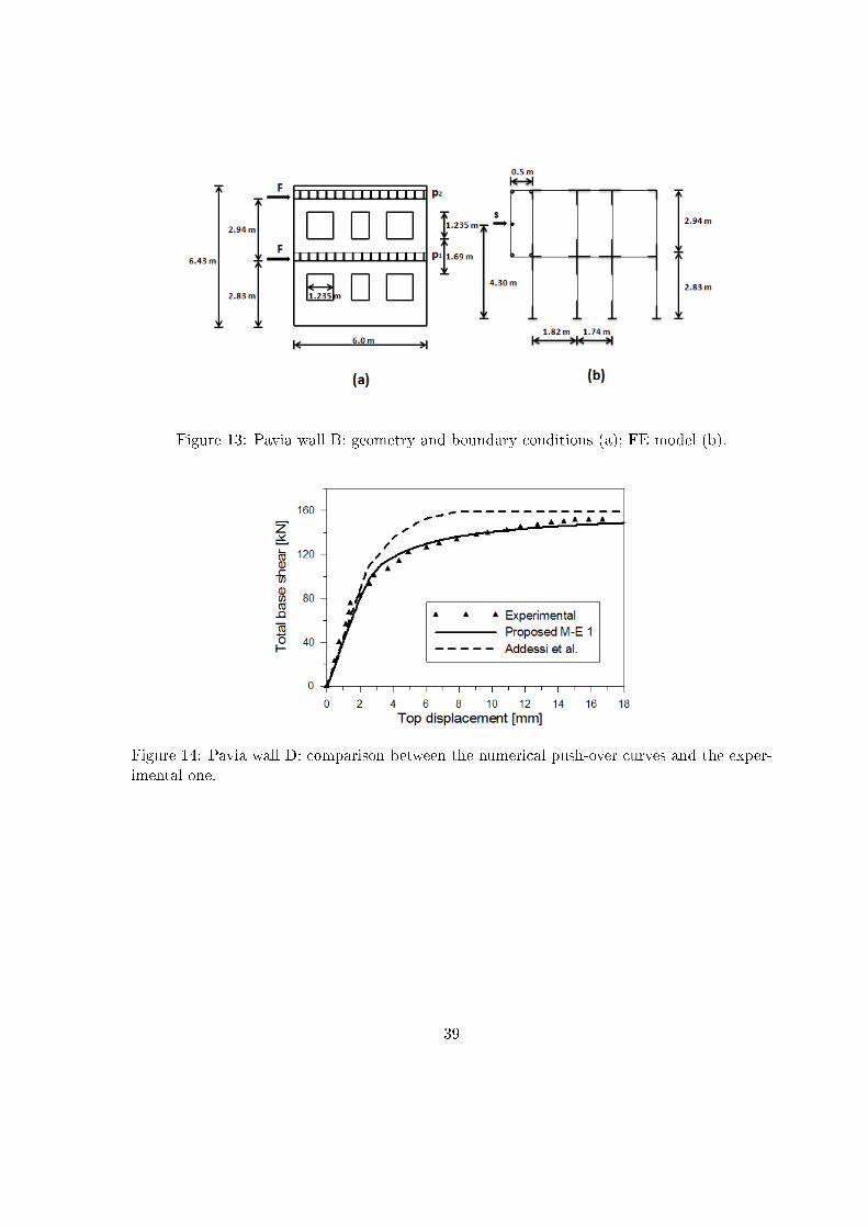
Figure 13: Pavia wall B: geometry and boundary conditions (a); FE model (b).
Figure 14: Pavia wall D: comparison between the numerical push-over curves and the exper-imental one.
39

Figure 15: Pavia wall D: total and single piers base shear.
Figure 16: Pavia wall D: total and single piers axial force.
40

Figure 17: Pavia wall D: distribution of the trust curves and of the shear hinges in the piersand spandrels at the three steps u = 3 mm (a), u = 8 mm (b) and u = 18 mm (c).
Figure 18: Pavia wall B: comparison between the numerical push-over curves and the exper-imental one.
41

Figure 19: Pavia wall B: total and single piers base shear.
Figure 20: Pavia wall B: total and single piers axial force.
42

Figure 21: Pavia wall B: distribution of the trust curves and of the shear hinges in the piersand spandrels at the three steps u = 5 mm (a), u = 7 mm (b) and u = 18 mm (c).
43
Related Documents