An Enriched Constitutive Model for Fracture Propagation Analysis using the Material Point Method Giang D. Nguyen 1, a 1 School of Civil, Environmental and Mining Engineering, The University of Adelaide, Australia a [email protected] / [email protected] Keywords: Material Point Method, Fracture Propagation, Damage Mechanics, Constitutive Modeling, Length scale, size effects. Abstract. We develop a novel constitutive modeling approach for the analysis of fracture propagation in quasi-brittle materials using the Material Point Method. The kinematics of constitutive models is enriched with an additional mode of localized deformation to take into account the strain discontinuity once cracking has occurred. The crack details therefore can be stored at material point level and there is no need to enrich the kinematics of finite elements to capture the localization caused by fracturing processes. This enhancement also removes the drawback of classical smeared crack approach in producing unphysical snapping back constitutive responses when the spatial resolution is not fine enough. All these facilitate the implementation of the new approach in the Material Point Method for analysis of large scale problems. Numerical examples of fracture propagation are used to demonstrate the effectiveness and potentials of the new approach. Introduction The Material Point Method (MPM; [1, 2]) is an enhanced derivation of the Finite Element Method (FEM) with moving integration points. Loosely speaking it is different from FEM in separating the computational grid with the representation of solids/structures using material points. The material points are allowed to move in and out of their elements. An algorithm is therefore required to map back and forth information from material points to finite element nodes for the solution of equilibrium equations and update of material points’ quantities (e.g. velocity, stress, strain). The finite element grid can be reset (or usually kept fixed) after a computational cycle, when all information has been mapped back to material points and their positions updated. The MPM therefore combines the advantages of both Eulerian (fixed grid) and Lagrangian (moving integration points) approaches, including avoidance of mesh distortion under large deformation, and can automatically handle no-slip contacts for impacting bodies. The representation of solids/structures with material points facilitates the use of any constitutive models and/or failure criteria associated with the material points. Examples for fracture propagation using MPM include smeared crack approach for the analysis of sea ice fracture [2]. This approach to fracture propagation analysis is easy to implement in any MPM code and can handle, at the constitutive level, multiple intersecting cracks. However besides the unphysical scaling of fracture properties, it suffers from the snap back constitutive response if the spatial resolution is not sufficiently fine, due to the lack of enhanced element kinematics to deal with discontinuities. On the other hand, enhancement to the finite element kinematics to capture discontinuities usually requires adding and storing additional quantities (such as crack sizes and orientations) independently or in the enriched elements. Alternatively, information such as crack sizes and orientation can also be stored at material points and mapped to grid nodes to construct an additional element kinematic field to account for the stress relaxation due to cracking [3]. In the literature, the CRAMP (CRAcks with Material Points [4]) algorithm provides another kind of enhancement in which the kinematics is enhanced via the use of multiple velocity fields, due to the presence of explicitly modeled cracks. This line of approach has obtained great success and been adapted to model a variety of problems involving material cracking ([4, 5]). However the above mentioned approaches may become more

Welcome message from author
This document is posted to help you gain knowledge. Please leave a comment to let me know what you think about it! Share it to your friends and learn new things together.
Transcript
An Enriched Constitutive Model for Fracture Propagation Analysis using the Material Point Method
Giang D. Nguyen1, a 1School of Civil, Environmental and Mining Engineering, The University of Adelaide, Australia
[email protected] / [email protected]
Keywords: Material Point Method, Fracture Propagation, Damage Mechanics, Constitutive Modeling, Length scale, size effects.
Abstract. We develop a novel constitutive modeling approach for the analysis of fracture propagation
in quasi-brittle materials using the Material Point Method. The kinematics of constitutive models is
enriched with an additional mode of localized deformation to take into account the strain
discontinuity once cracking has occurred. The crack details therefore can be stored at material point
level and there is no need to enrich the kinematics of finite elements to capture the localization caused
by fracturing processes. This enhancement also removes the drawback of classical smeared crack
approach in producing unphysical snapping back constitutive responses when the spatial resolution is
not fine enough. All these facilitate the implementation of the new approach in the Material Point
Method for analysis of large scale problems. Numerical examples of fracture propagation are used to
demonstrate the effectiveness and potentials of the new approach.
Introduction
The Material Point Method (MPM; [1, 2]) is an enhanced derivation of the Finite Element Method
(FEM) with moving integration points. Loosely speaking it is different from FEM in separating the
computational grid with the representation of solids/structures using material points. The material
points are allowed to move in and out of their elements. An algorithm is therefore required to map
back and forth information from material points to finite element nodes for the solution of equilibrium
equations and update of material points’ quantities (e.g. velocity, stress, strain). The finite element
grid can be reset (or usually kept fixed) after a computational cycle, when all information has been
mapped back to material points and their positions updated. The MPM therefore combines the
advantages of both Eulerian (fixed grid) and Lagrangian (moving integration points) approaches,
including avoidance of mesh distortion under large deformation, and can automatically handle no-slip
contacts for impacting bodies.
The representation of solids/structures with material points facilitates the use of any constitutive
models and/or failure criteria associated with the material points. Examples for fracture propagation
using MPM include smeared crack approach for the analysis of sea ice fracture [2]. This approach to
fracture propagation analysis is easy to implement in any MPM code and can handle, at the
constitutive level, multiple intersecting cracks. However besides the unphysical scaling of fracture
properties, it suffers from the snap back constitutive response if the spatial resolution is not
sufficiently fine, due to the lack of enhanced element kinematics to deal with discontinuities.
On the other hand, enhancement to the finite element kinematics to capture discontinuities usually
requires adding and storing additional quantities (such as crack sizes and orientations) independently
or in the enriched elements. Alternatively, information such as crack sizes and orientation can also be
stored at material points and mapped to grid nodes to construct an additional element kinematic field
to account for the stress relaxation due to cracking [3]. In the literature, the CRAMP (CRAcks with
Material Points [4]) algorithm provides another kind of enhancement in which the kinematics is
enhanced via the use of multiple velocity fields, due to the presence of explicitly modeled cracks. This
line of approach has obtained great success and been adapted to model a variety of problems
involving material cracking ([4, 5]). However the above mentioned approaches may become more
complicated and impractical when dealing with complex crack patterns involving many intersecting
cracks.
We take a different approach to modeling fracture propagation using the MPM in this paper.
Instead of enhancing finite elements to capture the discontinuities caused by cracking, the constitutive
model is enriched with an additional mode of localized deformation. In this sense, we want to retain
all advantages of the MPM in storing all information at material points, while addressing the strain
discontinuity via the enhanced constitutive model. It will also be shown that a length scale will
involve in the enrichment, thus providing the constitutive model a good way to capture size effects
due to localization. The paper is organized as follows. Enrichment to constitutive models will be
presented in the next section, together with a damage model for modeling failure of quasi-brittle
materials. This is followed by implementation algorithms for MPM and numerical examples of crack
propagations to demonstrate the effectiveness and potentials of the proposed algorithms.
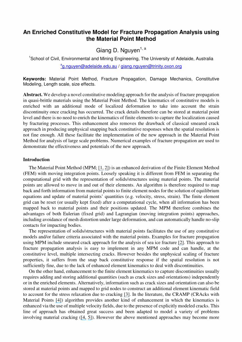
A kinematically enriched constitutive model
We take advantage of the fact that the
Fracture Process Zone (FPZ) in quasi-brittle
failure is usually very small compared to the
size of solids/structures under consideration.
Instead of embedding an oriented FPZ (or
more generally localization zone) in a finite
element, we do it in constitutive models. We
consider a volume Ω occupied by a material
point depicted in Fig. 1, for a two-dimensional (2D) problem. A localization zone of width h and
volume ΩL is embedded in this volume. We denote A the projected surface area of ΩL on the plane
taking n as its normal vector. It is therefore possible to define an effective size H=Ω/A of the volume
Ω so that the volume fraction f can be taken as the relative size of the FPZ with respect to Ω:
Ω
Ω
L hH
f = = . (1)
The configuration depicted in Fig. 1 can be viewed as a composite material possessing two
different phases: elastic phase for the bulk and inelastic phase for the embedded zone. The elastic bulk
is assumed here for quasi-brittle failure but is not a compulsory condition for the development. The
total strain rate in this case can be written as a volume averaged one with contributions from two
different phases:
( ) b1Lf f= + −ε ε ε . (2)
In the above equation, εεεε is the macroscopic strain, εεεεL the strain inside the localization zone, and εεεεb the
strain in the bulk continuum. For h<<H the strain rate inside this layer can be approximated as [6. 7]:
[ ]( ) [ ] [ ]( )1 12
s
L h h= ⊗ = ⊗ + ⊗ε n u n u u n . (3)
where [ů] is relative velocity between opposite sides of the thin FPZ. Due to this inelastic behavior,
the stress rate in the bulk continuum is relaxed and can be given by [6, 7]:
( )1b b b1 Lf
f−
= = −σ a : ε a : ε ε . (4)
For elastic behavior in the bulk, ab denotes the elastic stiffness tensor. On the other hand, inelastic
response is lumped onto the thin band and governed by the following generic constitutive
relationship, with aLT denoting the tangent stiffness of the material inside the localization zone:
TL L L=σ a : ε . (5)
Figure 1: A volume with an embedded localization
zone and disp. and strain profiles across the zone
h
A
n
εεεεb
εεεεL
εεεεb
H
h
[u]
As can be seen, we treat the material as a composite one consisting of two different phases with
corresponding behaviors. These behaviors are connected via an internal equilibrium condition to
maintain the continuity of traction across the boundary of the thin localization band:
( ) 0L− =σ σ n i . (6)
The incremental stress-strain relationship of the enriched material model can then be obtained by
substituting (3-5) into (6). We then obtain:
[ ]( ) [ ]( )1 1b1
s sf TLf h h−
− ⊗ = ⊗
a : ε n u n a : n u n i i . (7)
Therefore for a given macroscopic strain rate, the velocity jump [ů] can be worked out as:
[ ] ( )1b
−=u C a : ε n i i . (8)
where:
( ) ( )1b
f fTLh h
−= +C n a n n a ni i i i . (9)
Substituting (9) into (4) leads to the stress rate in the following form:
( )( )11b b1
sf
f h
−
−
= − ⊗ σ a : ε n C a : ε n i i . (10)
The composite response in this case is governed by the behavior of different phases (Eq. 4-5) and their
corresponding sizes. In principle, any constitutive relationship can be used for (4) and (5), as the
generic algorithm described here requires only the stiffnesses ab and aLT. Further details can be found
in [6, 7]. For quasi-brittle failure, it is reasonable to assume the elastic unloading for the bulk, while a
damage model can be used to describe progressing failure inside the localization band. Therefore we
take the following damage model governed by the following constitutive relationships [9]:
Stress-strain relationship ( )1L L LD= −σ a : ε . (11)
Damage criterion ( )
( ) ( )2
11L L
2 1: : 0L
Dy F D+ − +
−= − ≤σ a σ . (12)
where aL is the elastic stiffness tensor and D a scalar damage variable. The eigenvalue decomposition
[8] is used to decompose the stress tensor σσσσL into positive (σσσσL+) and negative parts. Function F(D) in
the above expression governs the damage evolution and inelastic response of the material inside the
localization zone. It takes the following form [9]:
( )( )
( ) ( )
22 1
2 1 1
npt
np
E E DfF D
E E D E D
+ −′ = − + −
. (13)
The above function uses the uniaxial tensile strength ft’, and two parameters Ep and n determined from
the fracture energy of the material. Details on how to do that can be found in [9].
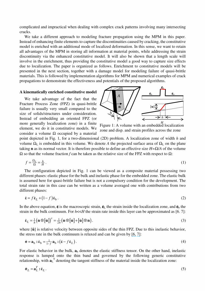
Implementation matters
The new enriched constitutive structure allows two different behaviors integrated in a constitutive
model, together with corresponding sizes. This facilitates the MPM implementation of the approach
as a material point now can carry both the elastic bulk and cracking behaviors with an embedded crack
(Fig. 2). A continuum damage type one described by Eqs. (11-13) is used in this paper for illustration
purpose and for quasi-brittle failure the orientation of the localization band is determined based on the
first principal stress. Discrete constitutive models such as the cohesive
crack can also be easily integrated in the approach. Details on this have
been presented in [7]. Although the memory storage for a material point
is double that of a regular constitutive model, due to the presence of an
additional stress and strain inside the localization zone, it only applies
to cracked material points. We know that the number of cracked
material points is usually small compared to the total number of
material points in a discretized solid, due to the localized nature of
failure.
The stress return algorithm for the above constitutive structure
requires enforcing the traction continuity (6), besides classical stress update algorithms for the
inelastic constitutive behavior inside the localization band. It has been described at length in [7]. The
focus here is the interface with the MPM, in which each material possess its own size. The effective
size H in this case is determined from the element, not the material point, to enforce the reproduction
of the correct fracture energy [10]. Following this, an algorithm
based on the crack orientation and element geometry, depicted
in Fig. 2, is proposed. Alternatively, a simplified one taking H
as the square root of element area in 2D also yield satisfactory
results, while facilitating the implementation in any existing
numerical code [7].
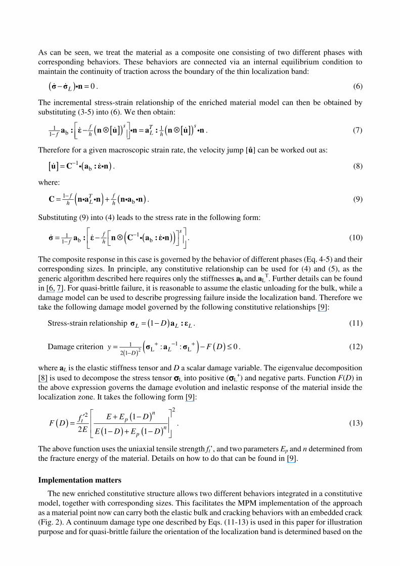
Numerical examples
We use the above enriched model and algorithms for the
analysis of quasi-brittle failure in concrete. The mixed mode
cracking of a double edge notched (DEN; Fig. 3) specimen is
numerically simulated in this example. The experimental tests
of the DEN specimens examined were carried out by [11], and the material properties are: Young
modulus E=32000MPa, Poisson’s ratio ν=0.2, uniaxial tensile strength ft’=3.0MPa, fracture energy
GF=0.011Nmm/mm2. For the h=0.05mm, the calibration procedure described in [9] gives
Ep=8.184MPa and n=0.128. We use three different uniform meshes with finite element sizes of
2.5*2.5mm2 (coarse), 1.25*1.25mm
2 (medium) and 0.625*0.625mm
2 (fine).
-5
0
5
10
15
20
0 0.02 0.04 0.06 0.08 0.1
Pn
(k
N)
δδδδn (mm)
experiment
coarse mesh
medium mesh
fine mesh
0
5
10
15
20
25
30
0 0.02 0.04 0.06 0.08 0.1
Ps
(kN
)
δδδδs (mm)
experiment
coarse mesh
medium mesh
fine mesh
Figure 4: Mesh dependent numerical results.
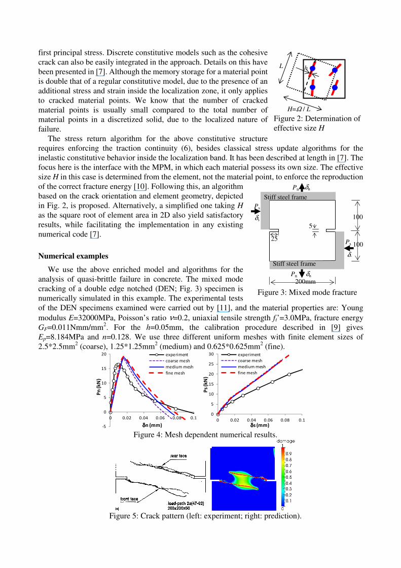
Figure 5: Crack pattern (left: experiment; right: prediction).
H=Ω / L
L h
Figure 2: Determination of
effective size H
200mm
25
Ps
Pn
5
100
Stiff steel frame
Stiff steel frame
δs
δn
Pn δn
Ps
δs
100
Figure 3: Mixed mode fracture
test
The numerical response in Fig. 4 shows the insensitiveness of the results with respect to the
resolution of the spatial discretization. The prediction of fracture propagation is compared with
experimental observation in Fig. 5, showing a good match in the crack pattern. The predictions can be
improved with the use of more advanced constitutive models for the localization zone. However this
is not covered within the scope of this paper.
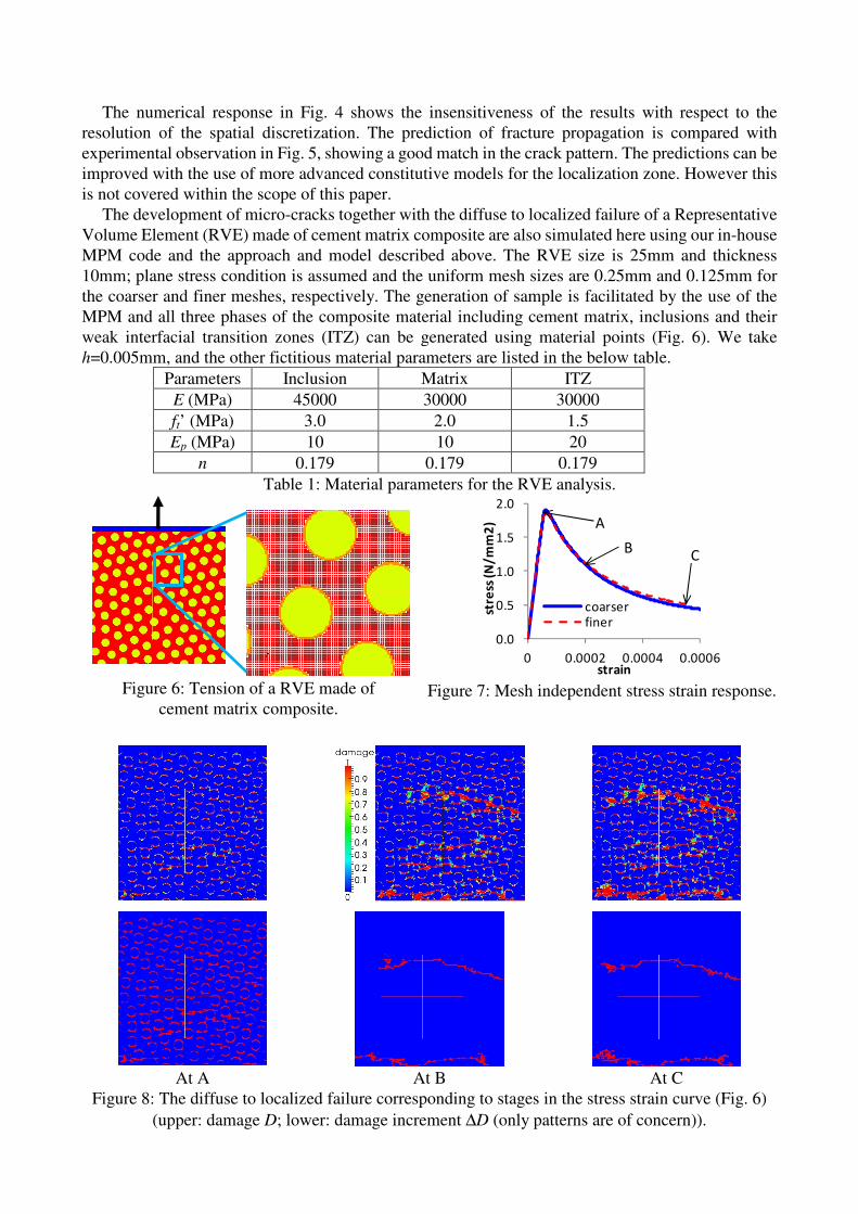
The development of micro-cracks together with the diffuse to localized failure of a Representative
Volume Element (RVE) made of cement matrix composite are also simulated here using our in-house
MPM code and the approach and model described above. The RVE size is 25mm and thickness
10mm; plane stress condition is assumed and the uniform mesh sizes are 0.25mm and 0.125mm for
the coarser and finer meshes, respectively. The generation of sample is facilitated by the use of the
MPM and all three phases of the composite material including cement matrix, inclusions and their
weak interfacial transition zones (ITZ) can be generated using material points (Fig. 6). We take
h=0.005mm, and the other fictitious material parameters are listed in the below table.
Parameters Inclusion Matrix ITZ
E (MPa) 45000 30000 30000
ft’ (MPa) 3.0 2.0 1.5
Ep (MPa) 10 10 20
n 0.179 0.179 0.179
Table 1: Material parameters for the RVE analysis.
0.0
0.5
1.0
1.5
2.0
0 0.0002 0.0004 0.0006
stre
ss (
N/
mm
2)
strain
coarser
finer
A
BC
Figure 7: Mesh independent stress strain response.
At A At B At C
Figure 8: The diffuse to localized failure corresponding to stages in the stress strain curve (Fig. 6)
(upper: damage D; lower: damage increment ∆D (only patterns are of concern)).
Figure 6: Tension of a RVE made of
cement matrix composite.
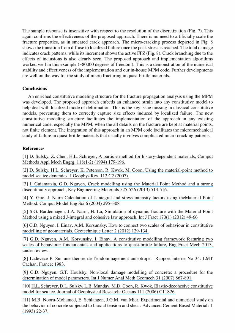
The sample response is insensitive with respect to the resolution of the discretization (Fig. 7). This
again confirms the effectiveness of the proposed approach. There is no need to artificially scale the
fracture properties, as in smeared crack approach. The micro-cracking process depicted in Fig. 8
shows the transition from diffuse to localized failure once the peak stress is reached. The total damage
indicates crack patterns, while its increment shows the active FPZ (Fig. 8). Crack branching due to the
effects of inclusions is also clearly seen. The proposed approach and implementation algorithms
worked well in this example (~80000 degrees of freedom). This is a demonstration of the numerical
stability and effectiveness of the implementation and our in-house MPM code. Further developments
are well on the way for the study of micro fracturing in quasi-brittle materials.
Conclusions
An enriched constitutive modeling structure for the fracture propagation analysis using the MPM
was developed. The proposed approach embeds an enhanced strain into any constitutive model to
help deal with localized mode of deformation. This is the key issue missing in classical constitutive
models, preventing them to correctly capture size effects induced by localized failure. The new
constitutive modeling structure facilitates the implementation of the approach in any existing
numerical code, especially the MPM, when the all details on the fracture are kept at material points,
not finite element. The integration of this approach in an MPM code facilitates the micromechanical
study of failure in quasi-brittle materials that usually involves complicated micro-cracking patterns.
References
[1] D. Sulsky, Z. Chen, H.L. Schreyer, A particle method for history-dependent materials, Comput
Methods Appl Mech Engrg. 118(1-2) (1994) 179-196.
[2] D. Sulsky, H.L. Schreyer, K. Peterson, R. Kwok, M. Coon, Using the material-point method to
model sea ice dynamics. J Geophys Res. 112 C2 (2007).
[3] I. Guiamatsia, G.D. Nguyen, Crack modelling using the Material Point Method and a strong
discontinuity approach, Key Engineering Materials 525-526 (2013) 513-516.
[4] Y. Guo, J. Nairn Calculation of J-integral and stress intensity factors using theMaterial Point
Method. Comput Model Eng Sci 6 (2004) 295–308
[5] S.G. Bardenhagen, J.A. Nairn, H. Lu, Simulation of dynamic fracture with the Material Point
Method using a mixed J-integral and cohesive law approach, Int J Fract 170(1) (2012) 49-66
[6] G.D. Nguyen, I. Einav, A.M. Korsunsky, How to connect two scales of behaviour in constitutive
modelling of geomaterials, Geotechnique Letter 2 (2012) 129-134.
[7] G.D. Nguyen, A.M. Korsunsky, I. Einav, A constitutive modelling framework featuring two
scales of behaviour: fundamentals and applications to quasi-brittle failure, Eng Fract Mech 2013,
under review.
[8] Ladeveze P. Sur une theorie de l’endommagement anisotrope. Rapport interne No 34: LMT
Cachan, France; 1983.
[9] G.D. Nguyen, G.T. Houlsby, Non-local damage modelling of concrete: a procedure for the
determination of model parameters. Int J Numer Anal Meth Geomech 31 (2007) 867-891.
[10] H.L. Schreyer, D.L. Sulsky, L.B. Munday, M.D. Coon, R. Kwok, Elastic-decohesive constitutive
model for sea ice. Journal of Geophysical Research: Oceans 111 (2006) C11S26.
[11] M.B. Nooru-Mohamed, E. Schlangen, J.G.M. van Mier, Experimental and numerical study on
the behavior of concrete subjected to biaxial tension and shear. Advanced Cement Based Materials 1
(1993) 22-37.
Related Documents


