INFORMATION AND COMMUNICATION SYSTEMS SECURITY An Empirical Approach of Wireless Forensics April 2009 Submitted by: Charlene Chow Ying Kwong Supervisor: Matei Ciobanu Morogan This thesis corresponds to 20 weeks of full-time work. DEPARTMENT OF COMPUTER AND SYSTEMS SCIENCES STOCKHOLM UNIVERSITY / ROYAL INSTITUTE OF TECHNOLOGY

Welcome message from author
This document is posted to help you gain knowledge. Please leave a comment to let me know what you think about it! Share it to your friends and learn new things together.
Transcript

INFORMATION AND COMMUNICATION SYSTEMS SECURITY
An Empirical Approach of Wireless Forensics
Apr i l 2009
Submit ted by: Char lene Chow Y ing Kwong
Superv i sor : Matei C iobanu Morogan
This thesis corresponds to 20 weeks of full-time work.
DEPARTMENT OF COMPUTER AND SYSTEMS SCIENCES STOCKHOLM UNIVERSITY / ROYAL INSTITUTE OF TECHNOLOGY

KTH/DSV (ICSS) AN EMPIRICAL APPROACH OF WIRELESS FORENSICS
| I
ABSTRACT
Wireless local area network (WLAN) based on 802.11 has rapidly gaining popularity in home user and enterprise environment. Flexibility, low costs and the tremendous growth of wireless devices have fueled the adoption of WLAN across the world. However the widespread of WLAN has also brought a new channel for digital crime and digital terrorism. By lacking of proper implementation of IEEE802.11, it takes just minutes for an intruder to break into the network. The police and forensics examiners have to deal with a fluid and no physical boundaries WLAN environment. A practical guideline will be helpful for them to collect the evidence in the scene.
This thesis depicts how a wireless forensic can be performed in IEEE 802.11b/g. The thesis suggests wireless forensics can be performed in five phases: network discovery, data capturing, key recovery, data analysis and wireless devices positioning. All five phases are discussed in details in terms of functionality and techniques. In the thesis, numerous of experiments have been carried out, including war driving in Stockholm city, performance testing of data capturing on different signal strength, comparison of WEP attack by Korek/FMS and PTW attack based on the number of packets, times estimation of dictionary attack by generating a English passphrase consisting digits, reconstruction of data packet in TCP and UDP, and locating the target devices by RSSI with 2 antennas. Experiments are used to evaluate and give a reference of the existing techniques, as well as prove the concept, which deduces all modules can be implemented in a Laptop for the wireless examiners to work in a dynamic environment.
Keywords: WEP, 802.11, 802.11i, WPA, WPA2, RSN, 802.11x, EAP, TKIP, AES, authentication, RTS/CTS, RFMON, Denial of Service, RSSI

KTH/DSV (ICSS) AN EMPIRICAL APPROACH OF WIRELESS FORENSICS
| II
ACKNOWLEDGMENT I would like to thank my academic supervisor, Matei Ciobanu Morogan, for his support, guidance and tolerance of my slow pace. This thesis is supposed to finish one year ago. Thank you for understanding and patience.
Besides, I have to thank my supervisor, Karol Krol in AirCapture AB, who guides and motivates me through the past year. AirCapture AB/TestTools AB is a second home for me, I am very grateful to my colleagues, who gave me the opportunities to learn and make me feel warm in my lonely days.
Last but not least, I would like to express my grateful to my beloved family and friends who support me and give me continuous love and care. When I am getting lazy, there are always voices kicking me to work hard.
KTH/DSV (ICSS) AN EMPIRICAL APPROACH OF WIRELESS FORENSICS
Table of Contents | III
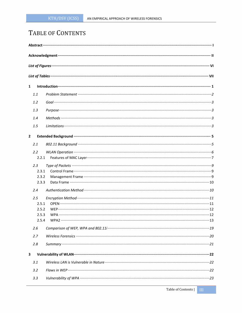
TABLE OF CONTENTS Abstract ∙∙∙∙∙∙∙∙∙∙∙∙∙∙∙∙∙∙∙∙∙∙∙∙∙∙∙∙∙∙∙∙∙∙∙∙∙∙∙∙∙∙∙∙∙∙∙∙∙∙∙∙∙∙∙∙∙∙∙∙∙∙∙∙∙∙∙∙∙∙∙∙∙∙∙∙∙∙∙∙∙∙∙∙∙∙∙∙∙∙∙∙∙∙∙∙∙∙∙∙∙∙∙∙∙∙∙∙∙∙∙∙∙∙∙∙∙∙∙∙∙∙∙∙∙∙∙∙∙∙∙∙∙∙∙∙∙∙∙∙∙∙∙∙∙∙∙∙∙∙∙∙∙∙∙∙∙∙ I
Acknowledgment ∙∙∙∙∙∙∙∙∙∙∙∙∙∙∙∙∙∙∙∙∙∙∙∙∙∙∙∙∙∙∙∙∙∙∙∙∙∙∙∙∙∙∙∙∙∙∙∙∙∙∙∙∙∙∙∙∙∙∙∙∙∙∙∙∙∙∙∙∙∙∙∙∙∙∙∙∙∙∙∙∙∙∙∙∙∙∙∙∙∙∙∙∙∙∙∙∙∙∙∙∙∙∙∙∙∙∙∙∙∙∙∙∙∙∙∙∙∙∙∙∙∙∙∙∙∙∙∙∙∙∙∙∙∙∙∙∙∙∙∙∙∙∙ II
List of Figures ∙∙∙∙∙∙∙∙∙∙∙∙∙∙∙∙∙∙∙∙∙∙∙∙∙∙∙∙∙∙∙∙∙∙∙∙∙∙∙∙∙∙∙∙∙∙∙∙∙∙∙∙∙∙∙∙∙∙∙∙∙∙∙∙∙∙∙∙∙∙∙∙∙∙∙∙∙∙∙∙∙∙∙∙∙∙∙∙∙∙∙∙∙∙∙∙∙∙∙∙∙∙∙∙∙∙∙∙∙∙∙∙∙∙∙∙∙∙∙∙∙∙∙∙∙∙∙∙∙∙∙∙∙∙∙∙∙∙∙∙∙∙∙∙∙∙∙∙ VI
List of Tables ∙∙∙∙∙∙∙∙∙∙∙∙∙∙∙∙∙∙∙∙∙∙∙∙∙∙∙∙∙∙∙∙∙∙∙∙∙∙∙∙∙∙∙∙∙∙∙∙∙∙∙∙∙∙∙∙∙∙∙∙∙∙∙∙∙∙∙∙∙∙∙∙∙∙∙∙∙∙∙∙∙∙∙∙∙∙∙∙∙∙∙∙∙∙∙∙∙∙∙∙∙∙∙∙∙∙∙∙∙∙∙∙∙∙∙∙∙∙∙∙∙∙∙∙∙∙∙∙∙∙∙∙∙∙∙∙∙∙∙∙∙∙∙∙∙∙∙∙ VII
1 Introduction ∙∙∙∙∙∙∙∙∙∙∙∙∙∙∙∙∙∙∙∙∙∙∙∙∙∙∙∙∙∙∙∙∙∙∙∙∙∙∙∙∙∙∙∙∙∙∙∙∙∙∙∙∙∙∙∙∙∙∙∙∙∙∙∙∙∙∙∙∙∙∙∙∙∙∙∙∙∙∙∙∙∙∙∙∙∙∙∙∙∙∙∙∙∙∙∙∙∙∙∙∙∙∙∙∙∙∙∙∙∙∙∙∙∙∙∙∙∙∙∙∙∙∙∙∙∙∙∙∙∙∙∙∙∙∙∙∙∙∙∙∙∙∙ 1
1.1 Problem Statement ∙∙∙∙∙∙∙∙∙∙∙∙∙∙∙∙∙∙∙∙∙∙∙∙∙∙∙∙∙∙∙∙∙∙∙∙∙∙∙∙∙∙∙∙∙∙∙∙∙∙∙∙∙∙∙∙∙∙∙∙∙∙∙∙∙∙∙∙∙∙∙∙∙∙∙∙∙∙∙∙∙∙∙∙∙∙∙∙∙∙∙∙∙∙∙∙∙∙∙∙∙∙∙∙∙∙∙∙∙∙∙∙∙∙∙∙∙∙∙∙∙∙∙∙∙∙∙∙∙∙∙∙∙∙ 2
1.2 Goal ∙∙∙∙∙∙∙∙∙∙∙∙∙∙∙∙∙∙∙∙∙∙∙∙∙∙∙∙∙∙∙∙∙∙∙∙∙∙∙∙∙∙∙∙∙∙∙∙∙∙∙∙∙∙∙∙∙∙∙∙∙∙∙∙∙∙∙∙∙∙∙∙∙∙∙∙∙∙∙∙∙∙∙∙∙∙∙∙∙∙∙∙∙∙∙∙∙∙∙∙∙∙∙∙∙∙∙∙∙∙∙∙∙∙∙∙∙∙∙∙∙∙∙∙∙∙∙∙∙∙∙∙∙∙∙∙∙∙∙∙∙∙∙∙∙∙∙∙∙∙∙∙∙∙∙∙∙∙ 3
1.3 Purpose∙∙∙∙∙∙∙∙∙∙∙∙∙∙∙∙∙∙∙∙∙∙∙∙∙∙∙∙∙∙∙∙∙∙∙∙∙∙∙∙∙∙∙∙∙∙∙∙∙∙∙∙∙∙∙∙∙∙∙∙∙∙∙∙∙∙∙∙∙∙∙∙∙∙∙∙∙∙∙∙∙∙∙∙∙∙∙∙∙∙∙∙∙∙∙∙∙∙∙∙∙∙∙∙∙∙∙∙∙∙∙∙∙∙∙∙∙∙∙∙∙∙∙∙∙∙∙∙∙∙∙∙∙∙∙∙∙∙∙∙∙∙∙∙∙∙∙∙∙∙∙∙∙ 3
1.4 Methods ∙∙∙∙∙∙∙∙∙∙∙∙∙∙∙∙∙∙∙∙∙∙∙∙∙∙∙∙∙∙∙∙∙∙∙∙∙∙∙∙∙∙∙∙∙∙∙∙∙∙∙∙∙∙∙∙∙∙∙∙∙∙∙∙∙∙∙∙∙∙∙∙∙∙∙∙∙∙∙∙∙∙∙∙∙∙∙∙∙∙∙∙∙∙∙∙∙∙∙∙∙∙∙∙∙∙∙∙∙∙∙∙∙∙∙∙∙∙∙∙∙∙∙∙∙∙∙∙∙∙∙∙∙∙∙∙∙∙∙∙∙∙∙∙∙∙∙∙∙∙∙ 3
1.5 Limitations ∙∙∙∙∙∙∙∙∙∙∙∙∙∙∙∙∙∙∙∙∙∙∙∙∙∙∙∙∙∙∙∙∙∙∙∙∙∙∙∙∙∙∙∙∙∙∙∙∙∙∙∙∙∙∙∙∙∙∙∙∙∙∙∙∙∙∙∙∙∙∙∙∙∙∙∙∙∙∙∙∙∙∙∙∙∙∙∙∙∙∙∙∙∙∙∙∙∙∙∙∙∙∙∙∙∙∙∙∙∙∙∙∙∙∙∙∙∙∙∙∙∙∙∙∙∙∙∙∙∙∙∙∙∙∙∙∙∙∙∙∙∙∙∙∙∙∙∙ 3
2 Extended Background ∙∙∙∙∙∙∙∙∙∙∙∙∙∙∙∙∙∙∙∙∙∙∙∙∙∙∙∙∙∙∙∙∙∙∙∙∙∙∙∙∙∙∙∙∙∙∙∙∙∙∙∙∙∙∙∙∙∙∙∙∙∙∙∙∙∙∙∙∙∙∙∙∙∙∙∙∙∙∙∙∙∙∙∙∙∙∙∙∙∙∙∙∙∙∙∙∙∙∙∙∙∙∙∙∙∙∙∙∙∙∙∙∙∙∙∙∙∙∙∙∙∙∙∙∙∙∙∙ 5
2.1 802.11 Background ∙∙∙∙∙∙∙∙∙∙∙∙∙∙∙∙∙∙∙∙∙∙∙∙∙∙∙∙∙∙∙∙∙∙∙∙∙∙∙∙∙∙∙∙∙∙∙∙∙∙∙∙∙∙∙∙∙∙∙∙∙∙∙∙∙∙∙∙∙∙∙∙∙∙∙∙∙∙∙∙∙∙∙∙∙∙∙∙∙∙∙∙∙∙∙∙∙∙∙∙∙∙∙∙∙∙∙∙∙∙∙∙∙∙∙∙∙∙∙∙∙∙∙∙∙∙∙∙∙∙∙∙∙∙ 5
2.2 WLAN Operation ∙∙∙∙∙∙∙∙∙∙∙∙∙∙∙∙∙∙∙∙∙∙∙∙∙∙∙∙∙∙∙∙∙∙∙∙∙∙∙∙∙∙∙∙∙∙∙∙∙∙∙∙∙∙∙∙∙∙∙∙∙∙∙∙∙∙∙∙∙∙∙∙∙∙∙∙∙∙∙∙∙∙∙∙∙∙∙∙∙∙∙∙∙∙∙∙∙∙∙∙∙∙∙∙∙∙∙∙∙∙∙∙∙∙∙∙∙∙∙∙∙∙∙∙∙∙∙∙∙∙∙∙∙∙∙∙∙∙ 6 2.2.1 Features of MAC Layer ∙∙∙∙∙∙∙∙∙∙∙∙∙∙∙∙∙∙∙∙∙∙∙∙∙∙∙∙∙∙∙∙∙∙∙∙∙∙∙∙∙∙∙∙∙∙∙∙∙∙∙∙∙∙∙∙∙∙∙∙∙∙∙∙∙∙∙∙∙∙∙∙∙∙∙∙∙∙∙∙∙∙∙∙∙∙∙∙∙∙∙∙∙∙∙∙∙∙∙∙∙∙∙∙∙∙∙∙∙∙∙∙∙∙∙∙∙∙∙∙∙∙∙∙∙ 7
2.3 Type of Packets ∙∙∙∙∙∙∙∙∙∙∙∙∙∙∙∙∙∙∙∙∙∙∙∙∙∙∙∙∙∙∙∙∙∙∙∙∙∙∙∙∙∙∙∙∙∙∙∙∙∙∙∙∙∙∙∙∙∙∙∙∙∙∙∙∙∙∙∙∙∙∙∙∙∙∙∙∙∙∙∙∙∙∙∙∙∙∙∙∙∙∙∙∙∙∙∙∙∙∙∙∙∙∙∙∙∙∙∙∙∙∙∙∙∙∙∙∙∙∙∙∙∙∙∙∙∙∙∙∙∙∙∙∙∙∙∙∙∙∙∙ 9 2.3.1 Control Frame ∙∙∙∙∙∙∙∙∙∙∙∙∙∙∙∙∙∙∙∙∙∙∙∙∙∙∙∙∙∙∙∙∙∙∙∙∙∙∙∙∙∙∙∙∙∙∙∙∙∙∙∙∙∙∙∙∙∙∙∙∙∙∙∙∙∙∙∙∙∙∙∙∙∙∙∙∙∙∙∙∙∙∙∙∙∙∙∙∙∙∙∙∙∙∙∙∙∙∙∙∙∙∙∙∙∙∙∙∙∙∙∙∙∙∙∙∙∙∙∙∙∙∙∙∙∙∙∙∙∙∙∙∙∙∙∙∙∙ 9 2.3.2 Management Frame ∙∙∙∙∙∙∙∙∙∙∙∙∙∙∙∙∙∙∙∙∙∙∙∙∙∙∙∙∙∙∙∙∙∙∙∙∙∙∙∙∙∙∙∙∙∙∙∙∙∙∙∙∙∙∙∙∙∙∙∙∙∙∙∙∙∙∙∙∙∙∙∙∙∙∙∙∙∙∙∙∙∙∙∙∙∙∙∙∙∙∙∙∙∙∙∙∙∙∙∙∙∙∙∙∙∙∙∙∙∙∙∙∙∙∙∙∙∙∙∙∙∙∙∙∙∙∙∙ 9 2.3.3 Data Frame ∙∙∙∙∙∙∙∙∙∙∙∙∙∙∙∙∙∙∙∙∙∙∙∙∙∙∙∙∙∙∙∙∙∙∙∙∙∙∙∙∙∙∙∙∙∙∙∙∙∙∙∙∙∙∙∙∙∙∙∙∙∙∙∙∙∙∙∙∙∙∙∙∙∙∙∙∙∙∙∙∙∙∙∙∙∙∙∙∙∙∙∙∙∙∙∙∙∙∙∙∙∙∙∙∙∙∙∙∙∙∙∙∙∙∙∙∙∙∙∙∙∙∙∙∙∙∙∙∙∙∙∙∙∙∙∙∙∙∙∙ 10
2.4 Authentication Method ∙∙∙∙∙∙∙∙∙∙∙∙∙∙∙∙∙∙∙∙∙∙∙∙∙∙∙∙∙∙∙∙∙∙∙∙∙∙∙∙∙∙∙∙∙∙∙∙∙∙∙∙∙∙∙∙∙∙∙∙∙∙∙∙∙∙∙∙∙∙∙∙∙∙∙∙∙∙∙∙∙∙∙∙∙∙∙∙∙∙∙∙∙∙∙∙∙∙∙∙∙∙∙∙∙∙∙∙∙∙∙∙∙∙∙∙∙∙∙∙∙∙∙∙∙∙ 10
2.5 Encryption Method ∙∙∙∙∙∙∙∙∙∙∙∙∙∙∙∙∙∙∙∙∙∙∙∙∙∙∙∙∙∙∙∙∙∙∙∙∙∙∙∙∙∙∙∙∙∙∙∙∙∙∙∙∙∙∙∙∙∙∙∙∙∙∙∙∙∙∙∙∙∙∙∙∙∙∙∙∙∙∙∙∙∙∙∙∙∙∙∙∙∙∙∙∙∙∙∙∙∙∙∙∙∙∙∙∙∙∙∙∙∙∙∙∙∙∙∙∙∙∙∙∙∙∙∙∙∙∙∙∙∙∙∙∙ 11 2.5.1 OPEN ∙∙∙∙∙∙∙∙∙∙∙∙∙∙∙∙∙∙∙∙∙∙∙∙∙∙∙∙∙∙∙∙∙∙∙∙∙∙∙∙∙∙∙∙∙∙∙∙∙∙∙∙∙∙∙∙∙∙∙∙∙∙∙∙∙∙∙∙∙∙∙∙∙∙∙∙∙∙∙∙∙∙∙∙∙∙∙∙∙∙∙∙∙∙∙∙∙∙∙∙∙∙∙∙∙∙∙∙∙∙∙∙∙∙∙∙∙∙∙∙∙∙∙∙∙∙∙∙∙∙∙∙∙∙∙∙∙∙∙∙∙∙∙∙∙∙∙∙∙∙ 11 2.5.2 WEP ∙∙∙∙∙∙∙∙∙∙∙∙∙∙∙∙∙∙∙∙∙∙∙∙∙∙∙∙∙∙∙∙∙∙∙∙∙∙∙∙∙∙∙∙∙∙∙∙∙∙∙∙∙∙∙∙∙∙∙∙∙∙∙∙∙∙∙∙∙∙∙∙∙∙∙∙∙∙∙∙∙∙∙∙∙∙∙∙∙∙∙∙∙∙∙∙∙∙∙∙∙∙∙∙∙∙∙∙∙∙∙∙∙∙∙∙∙∙∙∙∙∙∙∙∙∙∙∙∙∙∙∙∙∙∙∙∙∙∙∙∙∙∙∙∙∙∙∙∙∙∙∙ 12 2.5.3 WPA ∙∙∙∙∙∙∙∙∙∙∙∙∙∙∙∙∙∙∙∙∙∙∙∙∙∙∙∙∙∙∙∙∙∙∙∙∙∙∙∙∙∙∙∙∙∙∙∙∙∙∙∙∙∙∙∙∙∙∙∙∙∙∙∙∙∙∙∙∙∙∙∙∙∙∙∙∙∙∙∙∙∙∙∙∙∙∙∙∙∙∙∙∙∙∙∙∙∙∙∙∙∙∙∙∙∙∙∙∙∙∙∙∙∙∙∙∙∙∙∙∙∙∙∙∙∙∙∙∙∙∙∙∙∙∙∙∙∙∙∙∙∙∙∙∙∙∙∙∙∙∙ 12 2.5.4 WPA2 ∙∙∙∙∙∙∙∙∙∙∙∙∙∙∙∙∙∙∙∙∙∙∙∙∙∙∙∙∙∙∙∙∙∙∙∙∙∙∙∙∙∙∙∙∙∙∙∙∙∙∙∙∙∙∙∙∙∙∙∙∙∙∙∙∙∙∙∙∙∙∙∙∙∙∙∙∙∙∙∙∙∙∙∙∙∙∙∙∙∙∙∙∙∙∙∙∙∙∙∙∙∙∙∙∙∙∙∙∙∙∙∙∙∙∙∙∙∙∙∙∙∙∙∙∙∙∙∙∙∙∙∙∙∙∙∙∙∙∙∙∙∙∙∙∙∙∙∙∙ 13
2.6 Comparison of WEP, WPA and 802.11i ∙∙∙∙∙∙∙∙∙∙∙∙∙∙∙∙∙∙∙∙∙∙∙∙∙∙∙∙∙∙∙∙∙∙∙∙∙∙∙∙∙∙∙∙∙∙∙∙∙∙∙∙∙∙∙∙∙∙∙∙∙∙∙∙∙∙∙∙∙∙∙∙∙∙∙∙∙∙∙∙∙∙∙∙∙∙∙∙∙∙∙∙∙∙∙∙∙∙∙∙∙∙ 19
2.7 Wireless Forensics ∙∙∙∙∙∙∙∙∙∙∙∙∙∙∙∙∙∙∙∙∙∙∙∙∙∙∙∙∙∙∙∙∙∙∙∙∙∙∙∙∙∙∙∙∙∙∙∙∙∙∙∙∙∙∙∙∙∙∙∙∙∙∙∙∙∙∙∙∙∙∙∙∙∙∙∙∙∙∙∙∙∙∙∙∙∙∙∙∙∙∙∙∙∙∙∙∙∙∙∙∙∙∙∙∙∙∙∙∙∙∙∙∙∙∙∙∙∙∙∙∙∙∙∙∙∙∙∙∙∙∙∙∙∙ 20
2.8 Summary ∙∙∙∙∙∙∙∙∙∙∙∙∙∙∙∙∙∙∙∙∙∙∙∙∙∙∙∙∙∙∙∙∙∙∙∙∙∙∙∙∙∙∙∙∙∙∙∙∙∙∙∙∙∙∙∙∙∙∙∙∙∙∙∙∙∙∙∙∙∙∙∙∙∙∙∙∙∙∙∙∙∙∙∙∙∙∙∙∙∙∙∙∙∙∙∙∙∙∙∙∙∙∙∙∙∙∙∙∙∙∙∙∙∙∙∙∙∙∙∙∙∙∙∙∙∙∙∙∙∙∙∙∙∙∙∙∙∙∙∙∙∙∙∙∙∙∙∙ 21
3 Vulnerability of WLAN ∙∙∙∙∙∙∙∙∙∙∙∙∙∙∙∙∙∙∙∙∙∙∙∙∙∙∙∙∙∙∙∙∙∙∙∙∙∙∙∙∙∙∙∙∙∙∙∙∙∙∙∙∙∙∙∙∙∙∙∙∙∙∙∙∙∙∙∙∙∙∙∙∙∙∙∙∙∙∙∙∙∙∙∙∙∙∙∙∙∙∙∙∙∙∙∙∙∙∙∙∙∙∙∙∙∙∙∙∙∙∙∙∙∙∙∙∙∙∙∙∙∙∙∙∙∙∙ 22
3.1 Wireless LAN is Vulnerable in Nature ∙∙∙∙∙∙∙∙∙∙∙∙∙∙∙∙∙∙∙∙∙∙∙∙∙∙∙∙∙∙∙∙∙∙∙∙∙∙∙∙∙∙∙∙∙∙∙∙∙∙∙∙∙∙∙∙∙∙∙∙∙∙∙∙∙∙∙∙∙∙∙∙∙∙∙∙∙∙∙∙∙∙∙∙∙∙∙∙∙∙∙∙∙∙∙∙∙∙∙∙∙∙∙∙∙ 22
3.2 Flaws in WEP ∙∙∙∙∙∙∙∙∙∙∙∙∙∙∙∙∙∙∙∙∙∙∙∙∙∙∙∙∙∙∙∙∙∙∙∙∙∙∙∙∙∙∙∙∙∙∙∙∙∙∙∙∙∙∙∙∙∙∙∙∙∙∙∙∙∙∙∙∙∙∙∙∙∙∙∙∙∙∙∙∙∙∙∙∙∙∙∙∙∙∙∙∙∙∙∙∙∙∙∙∙∙∙∙∙∙∙∙∙∙∙∙∙∙∙∙∙∙∙∙∙∙∙∙∙∙∙∙∙∙∙∙∙∙∙∙∙∙∙∙∙∙ 22
3.3 Vulnerability of WPA ∙∙∙∙∙∙∙∙∙∙∙∙∙∙∙∙∙∙∙∙∙∙∙∙∙∙∙∙∙∙∙∙∙∙∙∙∙∙∙∙∙∙∙∙∙∙∙∙∙∙∙∙∙∙∙∙∙∙∙∙∙∙∙∙∙∙∙∙∙∙∙∙∙∙∙∙∙∙∙∙∙∙∙∙∙∙∙∙∙∙∙∙∙∙∙∙∙∙∙∙∙∙∙∙∙∙∙∙∙∙∙∙∙∙∙∙∙∙∙∙∙∙∙∙∙∙∙∙∙∙ 23
KTH/DSV (ICSS) AN EMPIRICAL APPROACH OF WIRELESS FORENSICS
Table of Contents | IV
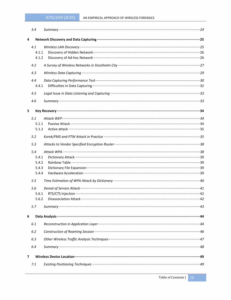
3.4 Summary ∙∙∙∙∙∙∙∙∙∙∙∙∙∙∙∙∙∙∙∙∙∙∙∙∙∙∙∙∙∙∙∙∙∙∙∙∙∙∙∙∙∙∙∙∙∙∙∙∙∙∙∙∙∙∙∙∙∙∙∙∙∙∙∙∙∙∙∙∙∙∙∙∙∙∙∙∙∙∙∙∙∙∙∙∙∙∙∙∙∙∙∙∙∙∙∙∙∙∙∙∙∙∙∙∙∙∙∙∙∙∙∙∙∙∙∙∙∙∙∙∙∙∙∙∙∙∙∙∙∙∙∙∙∙∙∙∙∙∙∙∙∙∙∙∙∙∙∙ 24
4 Network Discovery and Data Capturing ∙∙∙∙∙∙∙∙∙∙∙∙∙∙∙∙∙∙∙∙∙∙∙∙∙∙∙∙∙∙∙∙∙∙∙∙∙∙∙∙∙∙∙∙∙∙∙∙∙∙∙∙∙∙∙∙∙∙∙∙∙∙∙∙∙∙∙∙∙∙∙∙∙∙∙∙∙∙∙∙∙∙∙∙∙∙∙∙∙∙∙∙∙∙∙∙∙∙∙∙∙ 25
4.1 Wireless LAN Discovery ∙∙∙∙∙∙∙∙∙∙∙∙∙∙∙∙∙∙∙∙∙∙∙∙∙∙∙∙∙∙∙∙∙∙∙∙∙∙∙∙∙∙∙∙∙∙∙∙∙∙∙∙∙∙∙∙∙∙∙∙∙∙∙∙∙∙∙∙∙∙∙∙∙∙∙∙∙∙∙∙∙∙∙∙∙∙∙∙∙∙∙∙∙∙∙∙∙∙∙∙∙∙∙∙∙∙∙∙∙∙∙∙∙∙∙∙∙∙∙∙∙∙∙∙∙∙ 25 4.1.1 Discovery of Hidden Network ∙∙∙∙∙∙∙∙∙∙∙∙∙∙∙∙∙∙∙∙∙∙∙∙∙∙∙∙∙∙∙∙∙∙∙∙∙∙∙∙∙∙∙∙∙∙∙∙∙∙∙∙∙∙∙∙∙∙∙∙∙∙∙∙∙∙∙∙∙∙∙∙∙∙∙∙∙∙∙∙∙∙∙∙∙∙∙∙∙∙∙∙∙∙∙∙∙∙∙∙∙∙∙∙∙∙∙∙∙∙∙∙ 26 4.1.2 Discovery of Ad‐hoc Network ∙∙∙∙∙∙∙∙∙∙∙∙∙∙∙∙∙∙∙∙∙∙∙∙∙∙∙∙∙∙∙∙∙∙∙∙∙∙∙∙∙∙∙∙∙∙∙∙∙∙∙∙∙∙∙∙∙∙∙∙∙∙∙∙∙∙∙∙∙∙∙∙∙∙∙∙∙∙∙∙∙∙∙∙∙∙∙∙∙∙∙∙∙∙∙∙∙∙∙∙∙∙∙∙∙∙∙∙∙∙∙∙ 26
4.2 A Survey of Wireless Networks in Stockholm City ∙∙∙∙∙∙∙∙∙∙∙∙∙∙∙∙∙∙∙∙∙∙∙∙∙∙∙∙∙∙∙∙∙∙∙∙∙∙∙∙∙∙∙∙∙∙∙∙∙∙∙∙∙∙∙∙∙∙∙∙∙∙∙∙∙∙∙∙∙∙∙∙∙∙∙∙∙∙∙∙∙∙∙∙∙∙ 27
4.3 Wireless Data Capturing ∙∙∙∙∙∙∙∙∙∙∙∙∙∙∙∙∙∙∙∙∙∙∙∙∙∙∙∙∙∙∙∙∙∙∙∙∙∙∙∙∙∙∙∙∙∙∙∙∙∙∙∙∙∙∙∙∙∙∙∙∙∙∙∙∙∙∙∙∙∙∙∙∙∙∙∙∙∙∙∙∙∙∙∙∙∙∙∙∙∙∙∙∙∙∙∙∙∙∙∙∙∙∙∙∙∙∙∙∙∙∙∙∙∙∙∙∙∙∙∙∙∙∙∙ 29
4.4 Data Capturing Performance Test ∙∙∙∙∙∙∙∙∙∙∙∙∙∙∙∙∙∙∙∙∙∙∙∙∙∙∙∙∙∙∙∙∙∙∙∙∙∙∙∙∙∙∙∙∙∙∙∙∙∙∙∙∙∙∙∙∙∙∙∙∙∙∙∙∙∙∙∙∙∙∙∙∙∙∙∙∙∙∙∙∙∙∙∙∙∙∙∙∙∙∙∙∙∙∙∙∙∙∙∙∙∙∙∙∙∙∙∙∙∙ 30 4.4.1 Difficulties in Data Capturing ∙∙∙∙∙∙∙∙∙∙∙∙∙∙∙∙∙∙∙∙∙∙∙∙∙∙∙∙∙∙∙∙∙∙∙∙∙∙∙∙∙∙∙∙∙∙∙∙∙∙∙∙∙∙∙∙∙∙∙∙∙∙∙∙∙∙∙∙∙∙∙∙∙∙∙∙∙∙∙∙∙∙∙∙∙∙∙∙∙∙∙∙∙∙∙∙∙∙∙∙∙∙∙∙∙∙∙∙∙∙∙∙∙ 32
4.5 Legal Issue in Data Listening and Capturing ∙∙∙∙∙∙∙∙∙∙∙∙∙∙∙∙∙∙∙∙∙∙∙∙∙∙∙∙∙∙∙∙∙∙∙∙∙∙∙∙∙∙∙∙∙∙∙∙∙∙∙∙∙∙∙∙∙∙∙∙∙∙∙∙∙∙∙∙∙∙∙∙∙∙∙∙∙∙∙∙∙∙∙∙∙∙∙∙∙∙∙∙∙∙ 33
4.6 Summary ∙∙∙∙∙∙∙∙∙∙∙∙∙∙∙∙∙∙∙∙∙∙∙∙∙∙∙∙∙∙∙∙∙∙∙∙∙∙∙∙∙∙∙∙∙∙∙∙∙∙∙∙∙∙∙∙∙∙∙∙∙∙∙∙∙∙∙∙∙∙∙∙∙∙∙∙∙∙∙∙∙∙∙∙∙∙∙∙∙∙∙∙∙∙∙∙∙∙∙∙∙∙∙∙∙∙∙∙∙∙∙∙∙∙∙∙∙∙∙∙∙∙∙∙∙∙∙∙∙∙∙∙∙∙∙∙∙∙∙∙∙∙∙∙∙∙∙∙ 33
5 Key Recovery ∙∙∙∙∙∙∙∙∙∙∙∙∙∙∙∙∙∙∙∙∙∙∙∙∙∙∙∙∙∙∙∙∙∙∙∙∙∙∙∙∙∙∙∙∙∙∙∙∙∙∙∙∙∙∙∙∙∙∙∙∙∙∙∙∙∙∙∙∙∙∙∙∙∙∙∙∙∙∙∙∙∙∙∙∙∙∙∙∙∙∙∙∙∙∙∙∙∙∙∙∙∙∙∙∙∙∙∙∙∙∙∙∙∙∙∙∙∙∙∙∙∙∙∙∙∙∙∙∙∙∙∙∙∙∙∙∙∙∙∙ 34
5.1 Attack WEP ∙∙∙∙∙∙∙∙∙∙∙∙∙∙∙∙∙∙∙∙∙∙∙∙∙∙∙∙∙∙∙∙∙∙∙∙∙∙∙∙∙∙∙∙∙∙∙∙∙∙∙∙∙∙∙∙∙∙∙∙∙∙∙∙∙∙∙∙∙∙∙∙∙∙∙∙∙∙∙∙∙∙∙∙∙∙∙∙∙∙∙∙∙∙∙∙∙∙∙∙∙∙∙∙∙∙∙∙∙∙∙∙∙∙∙∙∙∙∙∙∙∙∙∙∙∙∙∙∙∙∙∙∙∙∙∙∙∙∙∙∙∙∙∙∙ 34 5.1.1 Passive Attack ∙∙∙∙∙∙∙∙∙∙∙∙∙∙∙∙∙∙∙∙∙∙∙∙∙∙∙∙∙∙∙∙∙∙∙∙∙∙∙∙∙∙∙∙∙∙∙∙∙∙∙∙∙∙∙∙∙∙∙∙∙∙∙∙∙∙∙∙∙∙∙∙∙∙∙∙∙∙∙∙∙∙∙∙∙∙∙∙∙∙∙∙∙∙∙∙∙∙∙∙∙∙∙∙∙∙∙∙∙∙∙∙∙∙∙∙∙∙∙∙∙∙∙∙∙∙∙∙∙∙∙∙∙∙∙∙ 34 5.1.2 Active attack ∙∙∙∙∙∙∙∙∙∙∙∙∙∙∙∙∙∙∙∙∙∙∙∙∙∙∙∙∙∙∙∙∙∙∙∙∙∙∙∙∙∙∙∙∙∙∙∙∙∙∙∙∙∙∙∙∙∙∙∙∙∙∙∙∙∙∙∙∙∙∙∙∙∙∙∙∙∙∙∙∙∙∙∙∙∙∙∙∙∙∙∙∙∙∙∙∙∙∙∙∙∙∙∙∙∙∙∙∙∙∙∙∙∙∙∙∙∙∙∙∙∙∙∙∙∙∙∙∙∙∙∙∙∙∙∙∙∙ 35
5.2 Korek/FMS and PTW Attack in Practice ∙∙∙∙∙∙∙∙∙∙∙∙∙∙∙∙∙∙∙∙∙∙∙∙∙∙∙∙∙∙∙∙∙∙∙∙∙∙∙∙∙∙∙∙∙∙∙∙∙∙∙∙∙∙∙∙∙∙∙∙∙∙∙∙∙∙∙∙∙∙∙∙∙∙∙∙∙∙∙∙∙∙∙∙∙∙∙∙∙∙∙∙∙∙∙∙∙∙∙∙∙ 35
5.3 Attacks to Vendor Specified Encryption Router ∙∙∙∙∙∙∙∙∙∙∙∙∙∙∙∙∙∙∙∙∙∙∙∙∙∙∙∙∙∙∙∙∙∙∙∙∙∙∙∙∙∙∙∙∙∙∙∙∙∙∙∙∙∙∙∙∙∙∙∙∙∙∙∙∙∙∙∙∙∙∙∙∙∙∙∙∙∙∙∙∙∙∙∙∙∙∙∙∙∙ 38
5.4 Attack WPA ∙∙∙∙∙∙∙∙∙∙∙∙∙∙∙∙∙∙∙∙∙∙∙∙∙∙∙∙∙∙∙∙∙∙∙∙∙∙∙∙∙∙∙∙∙∙∙∙∙∙∙∙∙∙∙∙∙∙∙∙∙∙∙∙∙∙∙∙∙∙∙∙∙∙∙∙∙∙∙∙∙∙∙∙∙∙∙∙∙∙∙∙∙∙∙∙∙∙∙∙∙∙∙∙∙∙∙∙∙∙∙∙∙∙∙∙∙∙∙∙∙∙∙∙∙∙∙∙∙∙∙∙∙∙∙∙∙∙∙∙∙∙∙∙ 38 5.4.1 Dictionary Attack ∙∙∙∙∙∙∙∙∙∙∙∙∙∙∙∙∙∙∙∙∙∙∙∙∙∙∙∙∙∙∙∙∙∙∙∙∙∙∙∙∙∙∙∙∙∙∙∙∙∙∙∙∙∙∙∙∙∙∙∙∙∙∙∙∙∙∙∙∙∙∙∙∙∙∙∙∙∙∙∙∙∙∙∙∙∙∙∙∙∙∙∙∙∙∙∙∙∙∙∙∙∙∙∙∙∙∙∙∙∙∙∙∙∙∙∙∙∙∙∙∙∙∙∙∙∙∙∙∙∙∙ 39 5.4.2 Rainbow Table ∙∙∙∙∙∙∙∙∙∙∙∙∙∙∙∙∙∙∙∙∙∙∙∙∙∙∙∙∙∙∙∙∙∙∙∙∙∙∙∙∙∙∙∙∙∙∙∙∙∙∙∙∙∙∙∙∙∙∙∙∙∙∙∙∙∙∙∙∙∙∙∙∙∙∙∙∙∙∙∙∙∙∙∙∙∙∙∙∙∙∙∙∙∙∙∙∙∙∙∙∙∙∙∙∙∙∙∙∙∙∙∙∙∙∙∙∙∙∙∙∙∙∙∙∙∙∙∙∙∙∙∙∙∙∙ 39 5.4.3 Dictionary File Expansion ∙∙∙∙∙∙∙∙∙∙∙∙∙∙∙∙∙∙∙∙∙∙∙∙∙∙∙∙∙∙∙∙∙∙∙∙∙∙∙∙∙∙∙∙∙∙∙∙∙∙∙∙∙∙∙∙∙∙∙∙∙∙∙∙∙∙∙∙∙∙∙∙∙∙∙∙∙∙∙∙∙∙∙∙∙∙∙∙∙∙∙∙∙∙∙∙∙∙∙∙∙∙∙∙∙∙∙∙∙∙∙∙∙∙∙∙∙∙∙ 39 5.4.4 Hardware Acceleration ∙∙∙∙∙∙∙∙∙∙∙∙∙∙∙∙∙∙∙∙∙∙∙∙∙∙∙∙∙∙∙∙∙∙∙∙∙∙∙∙∙∙∙∙∙∙∙∙∙∙∙∙∙∙∙∙∙∙∙∙∙∙∙∙∙∙∙∙∙∙∙∙∙∙∙∙∙∙∙∙∙∙∙∙∙∙∙∙∙∙∙∙∙∙∙∙∙∙∙∙∙∙∙∙∙∙∙∙∙∙∙∙∙∙∙∙∙∙∙∙∙∙ 39
5.5 Time Estimation of WPA Attack by Dictionary ∙∙∙∙∙∙∙∙∙∙∙∙∙∙∙∙∙∙∙∙∙∙∙∙∙∙∙∙∙∙∙∙∙∙∙∙∙∙∙∙∙∙∙∙∙∙∙∙∙∙∙∙∙∙∙∙∙∙∙∙∙∙∙∙∙∙∙∙∙∙∙∙∙∙∙∙∙∙∙∙∙∙∙∙∙∙∙∙∙∙∙ 40
5.6 Denial of Service Attack ∙∙∙∙∙∙∙∙∙∙∙∙∙∙∙∙∙∙∙∙∙∙∙∙∙∙∙∙∙∙∙∙∙∙∙∙∙∙∙∙∙∙∙∙∙∙∙∙∙∙∙∙∙∙∙∙∙∙∙∙∙∙∙∙∙∙∙∙∙∙∙∙∙∙∙∙∙∙∙∙∙∙∙∙∙∙∙∙∙∙∙∙∙∙∙∙∙∙∙∙∙∙∙∙∙∙∙∙∙∙∙∙∙∙∙∙∙∙∙∙∙∙∙∙∙∙ 41 5.6.1 RTS/CTS Injection ∙∙∙∙∙∙∙∙∙∙∙∙∙∙∙∙∙∙∙∙∙∙∙∙∙∙∙∙∙∙∙∙∙∙∙∙∙∙∙∙∙∙∙∙∙∙∙∙∙∙∙∙∙∙∙∙∙∙∙∙∙∙∙∙∙∙∙∙∙∙∙∙∙∙∙∙∙∙∙∙∙∙∙∙∙∙∙∙∙∙∙∙∙∙∙∙∙∙∙∙∙∙∙∙∙∙∙∙∙∙∙∙∙∙∙∙∙∙∙∙∙∙∙∙∙∙∙∙∙∙∙ 42 5.6.2 Disassociation Attack ∙∙∙∙∙∙∙∙∙∙∙∙∙∙∙∙∙∙∙∙∙∙∙∙∙∙∙∙∙∙∙∙∙∙∙∙∙∙∙∙∙∙∙∙∙∙∙∙∙∙∙∙∙∙∙∙∙∙∙∙∙∙∙∙∙∙∙∙∙∙∙∙∙∙∙∙∙∙∙∙∙∙∙∙∙∙∙∙∙∙∙∙∙∙∙∙∙∙∙∙∙∙∙∙∙∙∙∙∙∙∙∙∙∙∙∙∙∙∙∙∙∙∙∙∙ 42
5.7 Summary ∙∙∙∙∙∙∙∙∙∙∙∙∙∙∙∙∙∙∙∙∙∙∙∙∙∙∙∙∙∙∙∙∙∙∙∙∙∙∙∙∙∙∙∙∙∙∙∙∙∙∙∙∙∙∙∙∙∙∙∙∙∙∙∙∙∙∙∙∙∙∙∙∙∙∙∙∙∙∙∙∙∙∙∙∙∙∙∙∙∙∙∙∙∙∙∙∙∙∙∙∙∙∙∙∙∙∙∙∙∙∙∙∙∙∙∙∙∙∙∙∙∙∙∙∙∙∙∙∙∙∙∙∙∙∙∙∙∙∙∙∙∙∙∙∙∙∙∙ 43
6 Data Analysis ∙∙∙∙∙∙∙∙∙∙∙∙∙∙∙∙∙∙∙∙∙∙∙∙∙∙∙∙∙∙∙∙∙∙∙∙∙∙∙∙∙∙∙∙∙∙∙∙∙∙∙∙∙∙∙∙∙∙∙∙∙∙∙∙∙∙∙∙∙∙∙∙∙∙∙∙∙∙∙∙∙∙∙∙∙∙∙∙∙∙∙∙∙∙∙∙∙∙∙∙∙∙∙∙∙∙∙∙∙∙∙∙∙∙∙∙∙∙∙∙∙∙∙∙∙∙∙∙∙∙∙∙∙∙∙∙∙∙∙∙ 44
6.1 Reconstruction in Application Layer ∙∙∙∙∙∙∙∙∙∙∙∙∙∙∙∙∙∙∙∙∙∙∙∙∙∙∙∙∙∙∙∙∙∙∙∙∙∙∙∙∙∙∙∙∙∙∙∙∙∙∙∙∙∙∙∙∙∙∙∙∙∙∙∙∙∙∙∙∙∙∙∙∙∙∙∙∙∙∙∙∙∙∙∙∙∙∙∙∙∙∙∙∙∙∙∙∙∙∙∙∙∙∙∙∙∙∙ 44
6.2 Construction of Roaming Session ∙∙∙∙∙∙∙∙∙∙∙∙∙∙∙∙∙∙∙∙∙∙∙∙∙∙∙∙∙∙∙∙∙∙∙∙∙∙∙∙∙∙∙∙∙∙∙∙∙∙∙∙∙∙∙∙∙∙∙∙∙∙∙∙∙∙∙∙∙∙∙∙∙∙∙∙∙∙∙∙∙∙∙∙∙∙∙∙∙∙∙∙∙∙∙∙∙∙∙∙∙∙∙∙∙∙∙∙∙∙∙ 46
6.3 Other Wireless Traffic Analysis Techniques ∙∙∙∙∙∙∙∙∙∙∙∙∙∙∙∙∙∙∙∙∙∙∙∙∙∙∙∙∙∙∙∙∙∙∙∙∙∙∙∙∙∙∙∙∙∙∙∙∙∙∙∙∙∙∙∙∙∙∙∙∙∙∙∙∙∙∙∙∙∙∙∙∙∙∙∙∙∙∙∙∙∙∙∙∙∙∙∙∙∙∙∙∙∙∙∙ 47
6.4 Summary ∙∙∙∙∙∙∙∙∙∙∙∙∙∙∙∙∙∙∙∙∙∙∙∙∙∙∙∙∙∙∙∙∙∙∙∙∙∙∙∙∙∙∙∙∙∙∙∙∙∙∙∙∙∙∙∙∙∙∙∙∙∙∙∙∙∙∙∙∙∙∙∙∙∙∙∙∙∙∙∙∙∙∙∙∙∙∙∙∙∙∙∙∙∙∙∙∙∙∙∙∙∙∙∙∙∙∙∙∙∙∙∙∙∙∙∙∙∙∙∙∙∙∙∙∙∙∙∙∙∙∙∙∙∙∙∙∙∙∙∙∙∙∙∙∙∙∙∙ 48
7 Wireless Device Location ∙∙∙∙∙∙∙∙∙∙∙∙∙∙∙∙∙∙∙∙∙∙∙∙∙∙∙∙∙∙∙∙∙∙∙∙∙∙∙∙∙∙∙∙∙∙∙∙∙∙∙∙∙∙∙∙∙∙∙∙∙∙∙∙∙∙∙∙∙∙∙∙∙∙∙∙∙∙∙∙∙∙∙∙∙∙∙∙∙∙∙∙∙∙∙∙∙∙∙∙∙∙∙∙∙∙∙∙∙∙∙∙∙∙∙∙∙∙∙∙∙∙∙ 49
7.1 Existing Positioning Techniques ∙∙∙∙∙∙∙∙∙∙∙∙∙∙∙∙∙∙∙∙∙∙∙∙∙∙∙∙∙∙∙∙∙∙∙∙∙∙∙∙∙∙∙∙∙∙∙∙∙∙∙∙∙∙∙∙∙∙∙∙∙∙∙∙∙∙∙∙∙∙∙∙∙∙∙∙∙∙∙∙∙∙∙∙∙∙∙∙∙∙∙∙∙∙∙∙∙∙∙∙∙∙∙∙∙∙∙∙∙∙∙∙∙ 49
KTH/DSV (ICSS) AN EMPIRICAL APPROACH OF WIRELESS FORENSICS
Table of Contents | V
7.2 Locating Devices with RSSI and Two Antennas ∙∙∙∙∙∙∙∙∙∙∙∙∙∙∙∙∙∙∙∙∙∙∙∙∙∙∙∙∙∙∙∙∙∙∙∙∙∙∙∙∙∙∙∙∙∙∙∙∙∙∙∙∙∙∙∙∙∙∙∙∙∙∙∙∙∙∙∙∙∙∙∙∙∙∙∙∙∙∙∙∙∙∙∙∙∙∙∙∙∙ 50
7.3 Experiments of Positioning by RSSI from RTS/CTS and Two Antennas ∙∙∙∙∙∙∙∙∙∙∙∙∙∙∙∙∙∙∙∙∙∙∙∙∙∙∙∙∙∙∙∙∙∙∙∙∙∙∙∙∙∙∙∙∙∙∙∙∙∙∙∙∙∙∙ 53 7.3.1 RTS/CTS Mechanism in WLAN ∙∙∙∙∙∙∙∙∙∙∙∙∙∙∙∙∙∙∙∙∙∙∙∙∙∙∙∙∙∙∙∙∙∙∙∙∙∙∙∙∙∙∙∙∙∙∙∙∙∙∙∙∙∙∙∙∙∙∙∙∙∙∙∙∙∙∙∙∙∙∙∙∙∙∙∙∙∙∙∙∙∙∙∙∙∙∙∙∙∙∙∙∙∙∙∙∙∙∙∙∙∙∙∙∙∙∙∙∙∙∙ 53 7.3.2 RTS/CTS to any Station ∙∙∙∙∙∙∙∙∙∙∙∙∙∙∙∙∙∙∙∙∙∙∙∙∙∙∙∙∙∙∙∙∙∙∙∙∙∙∙∙∙∙∙∙∙∙∙∙∙∙∙∙∙∙∙∙∙∙∙∙∙∙∙∙∙∙∙∙∙∙∙∙∙∙∙∙∙∙∙∙∙∙∙∙∙∙∙∙∙∙∙∙∙∙∙∙∙∙∙∙∙∙∙∙∙∙∙∙∙∙∙∙∙∙∙∙∙∙∙∙∙∙ 54 7.3.3 RSSI Comparison in Directional Antenna and Omnidirectional Antenna ∙∙∙∙∙∙∙∙∙∙∙∙∙∙∙∙∙∙∙∙∙∙∙∙∙∙∙∙∙∙∙∙∙∙∙∙∙∙∙∙∙∙∙∙∙∙ 54
7.4 Summary ∙∙∙∙∙∙∙∙∙∙∙∙∙∙∙∙∙∙∙∙∙∙∙∙∙∙∙∙∙∙∙∙∙∙∙∙∙∙∙∙∙∙∙∙∙∙∙∙∙∙∙∙∙∙∙∙∙∙∙∙∙∙∙∙∙∙∙∙∙∙∙∙∙∙∙∙∙∙∙∙∙∙∙∙∙∙∙∙∙∙∙∙∙∙∙∙∙∙∙∙∙∙∙∙∙∙∙∙∙∙∙∙∙∙∙∙∙∙∙∙∙∙∙∙∙∙∙∙∙∙∙∙∙∙∙∙∙∙∙∙∙∙∙∙∙∙∙∙ 56
8 Conclusion ∙∙∙∙∙∙∙∙∙∙∙∙∙∙∙∙∙∙∙∙∙∙∙∙∙∙∙∙∙∙∙∙∙∙∙∙∙∙∙∙∙∙∙∙∙∙∙∙∙∙∙∙∙∙∙∙∙∙∙∙∙∙∙∙∙∙∙∙∙∙∙∙∙∙∙∙∙∙∙∙∙∙∙∙∙∙∙∙∙∙∙∙∙∙∙∙∙∙∙∙∙∙∙∙∙∙∙∙∙∙∙∙∙∙∙∙∙∙∙∙∙∙∙∙∙∙∙∙∙∙∙∙∙∙∙∙∙∙∙∙∙∙∙∙ 57
8.1 Future work: ∙∙∙∙∙∙∙∙∙∙∙∙∙∙∙∙∙∙∙∙∙∙∙∙∙∙∙∙∙∙∙∙∙∙∙∙∙∙∙∙∙∙∙∙∙∙∙∙∙∙∙∙∙∙∙∙∙∙∙∙∙∙∙∙∙∙∙∙∙∙∙∙∙∙∙∙∙∙∙∙∙∙∙∙∙∙∙∙∙∙∙∙∙∙∙∙∙∙∙∙∙∙∙∙∙∙∙∙∙∙∙∙∙∙∙∙∙∙∙∙∙∙∙∙∙∙∙∙∙∙∙∙∙∙∙∙∙∙∙∙∙∙∙ 57
9 Bibliography ∙∙∙∙∙∙∙∙∙∙∙∙∙∙∙∙∙∙∙∙∙∙∙∙∙∙∙∙∙∙∙∙∙∙∙∙∙∙∙∙∙∙∙∙∙∙∙∙∙∙∙∙∙∙∙∙∙∙∙∙∙∙∙∙∙∙∙∙∙∙∙∙∙∙∙∙∙∙∙∙∙∙∙∙∙∙∙∙∙∙∙∙∙∙∙∙∙∙∙∙∙∙∙∙∙∙∙∙∙∙∙∙∙∙∙∙∙∙∙∙∙∙∙∙∙∙∙∙∙∙∙∙∙∙∙∙∙∙∙∙∙ 59
10 Glossary ∙∙∙∙∙∙∙∙∙∙∙∙∙∙∙∙∙∙∙∙∙∙∙∙∙∙∙∙∙∙∙∙∙∙∙∙∙∙∙∙∙∙∙∙∙∙∙∙∙∙∙∙∙∙∙∙∙∙∙∙∙∙∙∙∙∙∙∙∙∙∙∙∙∙∙∙∙∙∙∙∙∙∙∙∙∙∙∙∙∙∙∙∙∙∙∙∙∙∙∙∙∙∙∙∙∙∙∙∙∙∙∙∙∙∙∙∙∙∙∙∙∙∙∙∙∙∙∙∙∙∙∙∙∙∙∙∙∙∙∙∙∙∙∙∙∙∙∙ 63
KTH/DSV (ICSS) AN EMPIRICAL APPROACH OF WIRELESS FORENSICS
List of Figures | VI
LIST OF FIGURES
Figure 1: Experiments performed in each phase ....................................................................................................... 3 Figure 2: Channel numbers and frequencies for 802.11b ...................................................................................... 6 Figure 3: WLAN architecture in infrastructure mode .............................................................................................. 7 Figure 4: CSMA/CA back‐Off Algorithm ......................................................................................................................... 8 Figure 5: Hidden node problem ......................................................................................................................................... 8 Figure 6: Authentication/association phase in a typical 802.11 network ..................................................... 10 Figure 7: Open authentication method, response with successful status only ............................................ 10 Figure 8: Challenge text sent in plaintext .................................................................................................................... 11 Figure 9: Encrypted challenge and its IVs ................................................................................................................... 11 Figure 10: Packet encryption by WEP .......................................................................................................................... 12 Figure 11: Authenticates process in 802.11i protocol ........................................................................................... 15 Figure 12: A Four‐way handshake ................................................................................................................................. 16 Figure 13: Derivation of pair wise transient key from PMK ................................................................................ 17 Figure 14: TKIP encryption process .............................................................................................................................. 18 Figure 15: CCMP encryption block, from (12) ........................................................................................................... 19 Figure 16: 5 phases in wireless forensics .................................................................................................................... 21 Figure 17: TKIP configuration in Linksys WRV200 ................................................................................................ 24 Figure 18: Network discovery by airodump‐ng ........................................................................................................ 26 Figure 19: MAC address illustration .............................................................................................................................. 27 Figure 20: Area of war driving in Stockholm ............................................................................................................. 28 Figure 21: War driving result –channels distribution ............................................................................................ 28 Figure 22: War driving result ‐ encryption method used ..................................................................................... 29 Figure 23: War driving result ‐ authentication methods used ........................................................................... 29 Figure 24: Experiment setup for data capturing performance test .................................................................. 31 Figure 25: PTW attack fails with insufficient ARP packets .................................................................................. 37 Figure 26: FMS/Korek Attack with lots of data packet .......................................................................................... 38 Figure 27: Increase of words with number of digit ................................................................................................. 41 Figure 28: DoS attack by aireplay‐ng ............................................................................................................................ 43 Figure 29: TCP packet depicts in Wireshark .............................................................................................................. 45 Figure 30: VoIP session decoded in Wireshark ........................................................................................................ 46 Figure 31: An overview of traffic from higher layer protocol in Colasoft ...................................................... 47 Figure 32: Colasoft shows all http request in the PCAP file ................................................................................. 47 Figure 33: Live image viewer in NetworkMiner ....................................................................................................... 48 Figure 34: Triangulation using three Access Points ............................................................................................... 50 Figure 35: RF antenna pattern in direction and omnidirectional ..................................................................... 52 Figure 36: 4‐way packet exchange: RTS‐>CTS‐>Data‐>ACK ............................................................................... 53 Figure 37: Injection of RTS/CTS Packet to power‐savings Station ................................................................... 54 Figure 38: Capturing analysis in monitor mode ....................................................................................................... 54 Figure 39: Map of floor the experiment is conducted ............................................................................................ 55 Figure 40:RSSI of directional antenna .......................................................................................................................... 56 Figure 41:RSSI of omnidirectional antenna ................................................................................................................ 56
KTH/DSV (ICSS) AN EMPIRICAL APPROACH OF WIRELESS FORENSICS
List of Tables | VII
LIST OF TABLES
Table 1: Summery of 802.11 protocols .......................................................................................................................... 6 Table 2: Comparison of WEP, WPA and RSN Security Protocol ......................................................................... 20 Table 3: war driving system configuration ................................................................................................................. 27 Table 4: Calibration of signal strength for data capturing ................................................................................... 31 Table 5: Data loss comparison in good, fair and weak signal strength ........................................................... 32 Table 6: Comparison of Korek/FMS and PTW attack in practice ...................................................................... 36 Table 7: WEP key recovery to Cisco Aironet 1200AP ............................................................................................ 38 Table 8: Estimation of time based on the English words ...................................................................................... 41 Table 9: Comparison of RSSI from antenna to find out the target .................................................................... 53 Table 10: System configuration for position experiments ................................................................................... 55
KTH/DSV (ICSS) AN EMPIRICAL APPROACH OF WIRELESS FORENSICS
Introduction 1
1 INTRODUCTION
Wireless network has prevalent existed due to their availability and inexpensive. A built‐in wireless card is an inevitable device in most of the portable device, such as PDA, mobile phone, UMPC and laptops. With a simple and low price router, people can have fast internet connection in every corner of their homes or offices. The flexibility and mobility have urged the popularity of wireless network.
However, the accessibility of wireless network has eased internet crime. The technology is used as a mean for illegal purposes, such as blackmail and intrusion to a private network. Criminals can simply connect through hotspot in airport, hotel or café. Wireless network uses radio frequency as a medium, which by nature is vulnerable. Every device with a wireless card might be able to connect to the wirelesses network if they are in the range of an Access Point.
The complexity of wireless networks has increased the difficulties of crime investigation for police and law enforcement. Intruders can easily break into the neighborhood’s network and make it as a channel to commit the crime. It is difficult to find out who the bad guy behind is. When the police trace down, it ends with an ISP without revealing the real intruder. The change of interaction among electronic devices in Wireless network creates challenges in evidence collection. A forensics examiner has to identify the possible misuse, and seek for a way to trace and collect the evidence.
Wireless forensics is a subset of computer forensics and involves process including capturing data packets, analysis of the packets, tracing the source of attacker and investigation if the wireless network has been used for illegal purpose. Based on the 7 processes suggested by the Digital Forensics Research Workshop (1), the thesis tailors the processes to fit with the wireless forensic and suggested a 5‐phase flow in wireless forensics. The phases begins with network discovery, data capturing, key recovery, data analysis and device positioning which are described from technical aspect and discussed separately in each chapter.
Network discovery is the first step of wireless forensics. It gives an overview of the networks around and spots out suspect if it is in among the networks. The range of detected networks can be increase by placing a stronger antenna. The next phase is to capture the data traffic. WLAN supports roaming, so it is important to capture all traffic in different channels. The capture should include all information of network and clients and the timestamp for law enforcement purpose. Thirdly, as WLAN is encrypted either by WEP or WPA, the secret key has to be recovered before data analysis. Ways of attacking WEP and WPA are different. It is easy to hack the WEP as long as there are enough packets. However, recovery of WPA by dictionary attack has to customize the dictionary according to the background of suspects. Fourthly, after the key is recovered, it is ready for data decryption and data analysis. Since there are huge data packets in the capturing, a summary report of packets from higher layer saves time for the examiner. A preview of images in live capturing helps to spot out the suspect immediately. Finally, as soon as the suspect is targeted, the police have to catch the intruder at the scene. The intruder is smart enough to stay somewhere far away

KTH/DSV (ICSS) AN EMPIRICAL APPROACH OF WIRELESS FORENSICS
Introduction | 2
but enough for network access. A simple positioning technique based on RSSI extracted from received CTS packets on both omnidirectional and directional antenna is used to identify the direction of suspect.
In each of the phase, different techniques and experiments are performed to prove the feasibility. The five phases give a comprehensive work flow in wireless forensics which can be a reference to forensics examiners.
The remainder of this thesis is organized as follows. Chapter 2 explains the background of IEEE 802.11. Chapter 3 describes the vulnerability of wireless LANs. Chapters 4 presents network discovery and data capturing. Chapter 5 discusses the key recovery techniques in both WEP and WPA. Chapter 6 illustrates the data analysis with wireless traffic. Chapter 7 provides the description of the proposed locating device method. Chapter 8 concludes with a brief summary and future work.
1.1 PROBLEM STATEMENT
Wireless LAN is inherently insecure compared with wired network. In wired network, data is transmitted through the cable and the only way to access the data is tapping the medium. In a wireless network, data is transmitted through radio frequency. The signal is broadcasted in the air and everyone in the range is able to intercept.
Many users don’t configure the Access Point securely enough, and some are just use the default setting. Hackers can just use these Access Points as a stepping‐stone to perform the attack. The insecurity of IEEE802.11 protocol allows intruders easily break into the WLAN or fool wireless devices. Wired Equivalent Privacy (WEP) is the first encryption protocol and has been broken in 2001. The next encryption protocol, 802.11i, is not flawless where weak key can be broken by dictionary attack.
No matter which encryption protocol is in use, WLAN is still vulnerable at Media Access Control layer and during association process. IEEE802.11 defines management frames and control frames for the establishment of network and media control purpose. However these frames are unencrypted, which means it is easy to trick the network and perform Denial of Service attack. Besides, interference can be caused through same frequency spectrum, such as cordless phone or Bluetooth.
Crimes have been committed in different areas through WLAN, both in enterprise environment and campus. Hackers hacked into Marshalls’ network and stole 200 million credit card numbers in 18 months (2). The state Anti‐Terrorism Squad traced the email sent from Khalsa College and revealed its contents related to terrorism (3). Unsecure WLAN has also used to send the email to the news organization just five minutes before the Ahmedabad explosion in India (3). The WLAN technology has been a challenge for the police and forensics examiners to investigate crimes, collect the evidence and catch the intruders.

KTH/DSV (ICSS) AN EMPIRICAL APPROACH OF WIRELESS FORENSICS
Introduction | 3
1.2 GOAL
The goal of this thesis is to describe the whole wireless forensics process from phase to phase, discuss the techniques and carry on experiments in each phase in practice to prove the feasibility.
1.3 PURPOSE
The purpose is to describe a systematic way in wireless forensics to handle the complexity in WLAN. The document can be a guide for the forensic examiners and non‐specialists, who are interested to have a thorough understanding in wireless weakness and forensics.
1.4 METHODS
Wireless forensics has not been widely discussed in the area, but the crimes happened in Wireless LAN urges a comprehensive and friendly solution for the forensics examiners. The research builds on both inductive approach and deductive approach. A literature review offers an understanding of the technology and the existing methods. By determining wireless forensics can be divided into five phases, the literature review covers techniques in network discovery, data capturing, attacks to WLAN, data analysis and devices positioning, and then defines the requirement and functionality a wireless forensics tool should include. Qualitative data are collected from literature study and working experience in Wireless LAN which includes customer requirement, system specification in wireless commercial tools and open source tools. Following the data gathered, experiments are setup to empirically prove the feasibility of functionalities suggested in the wireless forensics tool. The experiments are carried on and quantitative data are discussed in each phase. Figure 1 shows experiments performed in each phase.
FIGURE 1: EXPERIMENTS PERFORMED IN EACH PHASE
1.5 LIMITATIONS
The limitations of thesis are as follows:
• Only 802.11b/g is considered in the experiments , 802.11a and 802.11n are excluded
Netowk Discovery
•A survey of WLAN in Stockholm city
Data Capturing
•Data capturing performance test at signal level good, fair and weak
Key Recovery
•Comparison of Korek/FMS attack in terms of no. of packets
•Attacks to Cisco Aironet 1200AP
•Times estimation of WPA dictionary attack
•Denial of service attack
Data Analysis
•Reconstruction of TCP & UDP in wireshark
Device Positioning
•Positioning by RSSI from RTS/CTS and two antennas
KTH/DSV (ICSS) AN EMPIRICAL APPROACH OF WIRELESS FORENSICS
Introduction | 4
• This thesis doesn’t focus on the legal issue of a specific country and all issues are discussed in general rules and laws
• The experiments are carried at home environment which may not be a standard and the equipments are not professional
• All techniques and tastings are proof‐of‐concept, there is no implementation to combine all the functions in the useable system
KTH/DSV (ICSS) AN EMPIRICAL APPROACH OF WIRELESS FORENSICS
Extended Background | 5
2 EXTENDED BACKGROUND
Wireless network uses radio frequency (RF) as a medium. RF refers to any signal between the frequencies of 3Hz and 300GHz. IEEE committee Group specifies 802.11 which define an Ethernet‐like communication channel using radios operating over unlicensed radio spectrum bands and is called Wireless Local Area Networks (WLAN). The release consists of physical layer and media access‐channel layer specification. This chapter lays out the groundwork of 802.11 protocols.
2.1 802.11 BACKGROUND
The Institute of Electrical and Electronics engineers (IEEE) started working on the wireless standard in the unlicensed Industrial, Scientific and Medical (ISM) spectrum since 1990. The original version was released in 1997, which described the communication in WLAN with the purpose of adding flexibility and mobility to networking (4). Amendment and addition are added on the original version with suffix letter attached to 802.11 to represent different standards. Each standard is backward compatible and interoperable of various standards. The most commonly used standards are 802.11a, 802.11b, 802.11g and 802.11n.
IEEE802.11, called the legacy protocol, specified typical data rate of 1Mbit/s and maximum data rate 2Mbit/s. It transmits over the ISM band at 2.4GHz, which has been heavily shared, such as microwave, Bluetooth device and cordless phone. It allows two way of encoding information at physical level: Frequency Hopping Spread Spectrum (FHSS) and Direction Sequence Spread Spectrum (DSSS).
In 1999, 802.11a made two important additions on the legacy standard. It operates on 5GHz frequency band with numerous new frequency channel and new modulation Orthogonal Frequency Division Multiplexing (OFDM) coupling with advanced modulation techniques such as 16‐QAM and 64‐QAM (5). The new frequency utilization avoids the interferences problem as in 2.4GHz band, but the range of 5GHz is about one third shorter than 2.4GHz due to they are readily to be absorbed by walls and other solid objects. The new modulation technique enables a maximum data rate of 54 Mbit/s. However, 802.11a has never been popular among home and office users. Many routers don’t embrace 802.11a.
802.11b was also released in 1999. It is the first widely accepted standard which operates on 2.4GHz ISM band and supports data rate of 11Mbit/s with the complementary cod keying (CCK) modulation. 802.11b supports 14 channels. As seen from Figure 2, the corresponding channels overlap and cause interference problems. Only channel 1, channel 6 and channel 11 can coexist without interference problem. 802.11b can deliver a range of about 150feet.

KTH/DSV (ICSS) AN EMPIRICAL APPROACH OF WIRELESS FORENSICS
Extended Background | 6
FIGURE 2: CHANNEL NUMBERS AND FREQUENCIES FOR 802.11B
802.11g was released in 2003, which was a hybrid combination of both the 802.11a and 802.11b. It operates in 2.4GHz and uses the same modulation techniques, OFDM, as 802.11a. 802.11g allows maximum data rate 54Mbit/s. 802.11g is fully interoperable and shares the same channels with 802.11b. However, enabling both 802.11b and 802.11g in a WLAN, will reduce the overall data rate in a 802.11g network (5).
802.11n aims to have a data rate over 100 Mbit/s and draft n has been published at the end of 2007. It adds multiple‐input multiple‐output (MIMO) and operates at both 2.4GHz and 5GHz band. 802.11n requires new hardware infrastructure to support MIMO. Table 1 lists the summary of all protocols discussed.
TABLE 1: SUMMERY OF 802.11 PROTOCOLS
Protocol Frequency Band Typical Data Rate Maximum Data Rate Legacy 2.4 GHz 1 Mbit/s 2 Mbit/s 802.11a 5 GHz 25 Mbit/s 54 Mbit/s 802.11b 2.4 GHz 6.5 Mbit/s 11 Mbit/s 802.11g 2.4 GHz 11 Mbit/s 54 Mbit/s 802.11n 2.4 and 5 GHz 200 Mbit/s 540 Mbit/s
2.2 WLAN OPERATION
802.11 categorizes into two architect modes: Ad‐hoc and Infrastructure. In Ad‐hoc mode, each mobile station (STA) connects with each other and forms Independent Basic Service Set (IBSS). In this mode, all mobile stations communicate in peer role. There is no base and control of permission to talk. Ad‐hoc network helps to set up connectivity in dynamic or temporary environment, where the infrastructure itself is not necessary. Infrastructure mode is created when one station interconnects to the network that forms Distribution System which makes the network coverage increases and extends it to be part of a larger network (Figure 3). The station that connects all mobile stations is called Access Point (AP).

KTH/DSV (ICSS) AN EMPIRICAL APPROACH OF WIRELESS FORENSICS
Extended Background | 7
FIGURE 3: WLAN ARCHITECTURE IN INFRASTRUCTURE MODE
The IEEE Group does not define the implementation of Infrastructure architecture but they specify the concept of “services” that needs to be supported. This service is divided in two main parts: Station Services (SS) and Distribution System Services (DSS) (6). SS has the services of authentication, de‐authentication, confidentiality, and MAC service data unit delivery. DSS has five primitives: Association, Re‐association, Disassociation, Distribution and Integration, which are used for establishment, changing Access Point, removing the station, delivering frames to destination address in infrastructure network and delivering frames outside the WLAN respectively. The access of medium is contention based, but there is not collision detection as in wired network.
2.2.1 FEATURES OF MAC LAYER
The 802.11 defines two modes of operation in Media Access Control (MAC) layer, which is contention free and contention based. Contention appears when more than one station wants to use the medium which causes data collision.
In contention based MAC, stations have to compete for access the medium. As in Ethernet network, a station (STA) waits until the medium is free, and then transmits the packet. If more than one STA transmits at the same time, collision is detected and the STAs will bakeoff randomly. However, wireless adapter has one radio only. It can only transmit or receive. Therefore IEEE 802.11 employs Carrier Sense Multiple Access/Collision Avoidance (CSMA/CA) (Figure 4). This mode is called Distributed Coordination Function (DCF). In DCF mode, a STA waits until the medium is free and transmits the packet, and then the STA will wait for Acknowledge (ACK) packet. If the ACK packet is not received, the STA will resend the packet again.

KTH/DSV (ICSS) AN EMPIRICAL APPROACH OF WIRELESS FORENSICS
Extended Background | 8
FIGURE 4: CSMA/CA BACKOFF ALGORITHM
In a contention free MAC protocol, no collision is allowed, that means all STAs are time synchronized in some way (7). The mode operates in 802.11 MAC is called Point Coordination Function (PCF) (8). In PCF mode, the Access Point will control the use of medium, similar as operation in token ring. Access Point will poll each STA if they have any data to send.
Besides, the positive ACK packet is at the link layer instead of transport layer in Ethernet, which aims to save the time in delay for retransmission. Positive ACK is combined with fragmentation to increase the throughput across a noisy link. A single large frame is forced to reassembly at the next hop instead of final destination to save the time in retransmission.
Furthermore, a unique feature has employed in 802.11 to discover the hidden node. STAs in the WLAN may not able to hear each other, but the Access Point can hear all of them. As to avoid two STAs, who cannot hear each other, transmit at the same time, the IEEE 802.11 committee specifies Request to Send (RTS) and Clear to Send (CTS) mechanism (Figure 5). The STA has to send a RTS packet the Access Point prior sending data packet and waits for CTS. The Access Point responds with CTS to tell all STAs in the range to postpone any intended transmissions for a specified duration. Then the sender can have time to send the data packet and get ACK form Access Point. The specified duration includes the transmission time for CTS, data packet and ACK packets. RTS and CTS packets improve the throughput in the noisy link and the transmission of large packets.
FIGURE 5: HIDDEN NODE PROBLEM
STA A tData
STA B tData
CCA
CCA
Free
Free
Collision Random back off CCA
Free
Data
CCA
Busy
Data
CCA
Free
KTH/DSV (ICSS) AN EMPIRICAL APPROACH OF WIRELESS FORENSICS
Extended Background | 9
2.3 TYPE OF PACKETS
All packets can be categorized into data, management and control packets. Under each type of packet, there are subtype packets.
2.3.1 CONTROL FRAME
Control packet operates in the lowest level and relates directly to MAC rules. There are 6 subtype packets, but only four of them are in use: RTS, CTS, ACK, and power save poll. RTS, CTS and ACK have been discussed in section 2.2.1. Power save poll is used for STA to retrieve buffered packet from the Access Point when it is in power save mode (8). All control packets are unauthenticated and unencrypted.
2.3.2 MANAGEMENT FRAME
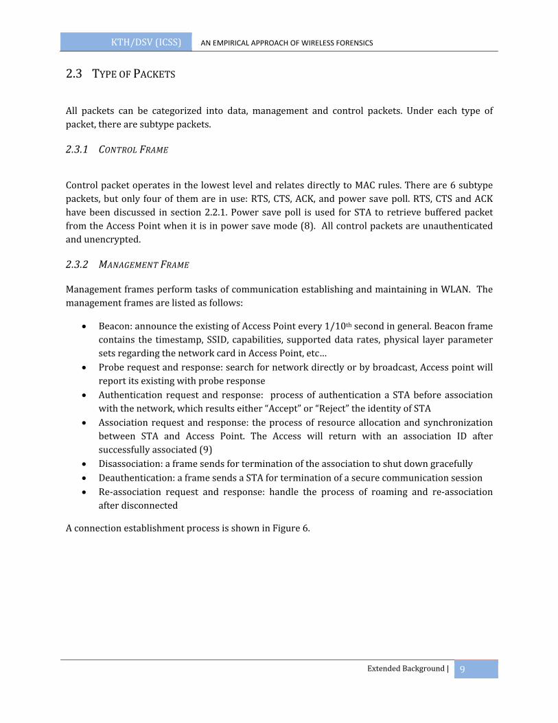
Management frames perform tasks of communication establishing and maintaining in WLAN. The management frames are listed as follows:
• Beacon: announce the existing of Access Point every 1/10th second in general. Beacon frame contains the timestamp, SSID, capabilities, supported data rates, physical layer parameter sets regarding the network card in Access Point, etc…
• Probe request and response: search for network directly or by broadcast, Access point will report its existing with probe response
• Authentication request and response: process of authentication a STA before association with the network, which results either “Accept” or “Reject” the identity of STA
• Association request and response: the process of resource allocation and synchronization between STA and Access Point. The Access will return with an association ID after successfully associated (9)
• Disassociation: a frame sends for termination of the association to shut down gracefully • Deauthentication: a frame sends a STA for termination of a secure communication session • Re‐association request and response: handle the process of roaming and re‐association
after disconnected
A connection establishment process is shown in Figure 6.
KTH/DSV (ICSS) AN EMPIRICAL APPROACH OF WIRELESS FORENSICS
Extended Background | 10
FIGURE 6: AUTHENTICATION/ASSOCIATION PHASE IN A TYPICAL 802.11 NETWORK
2.3.3 DATA FRAME
Data frame is the data to transmit over the network. Data packet is encrypted with WEP or WPA, except in the OPEN network. There are two types of data frame. One is the actual data and the other one is Null function data packet which is used to inform the Access Point the change of power saving mode of a STA.
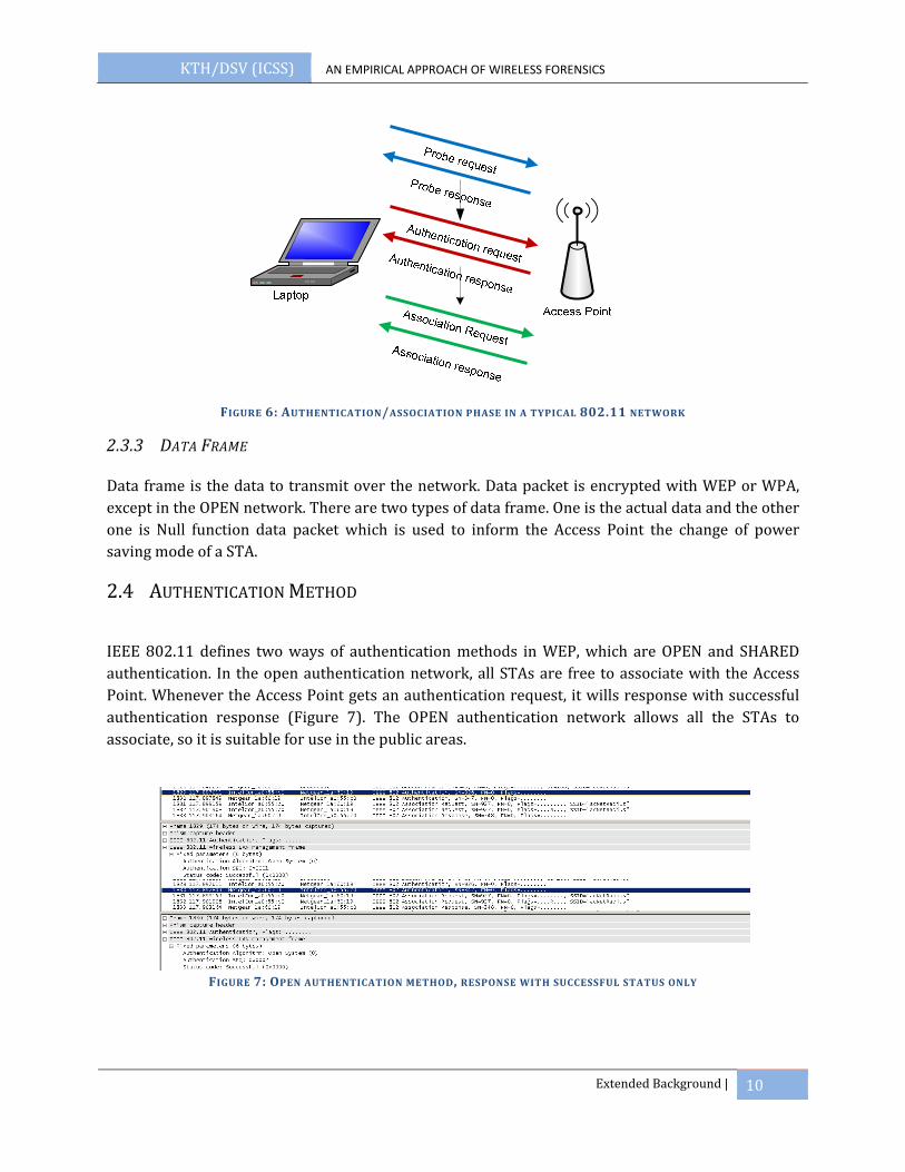
2.4 AUTHENTICATION METHOD
IEEE 802.11 defines two ways of authentication methods in WEP, which are OPEN and SHARED authentication. In the open authentication network, all STAs are free to associate with the Access Point. Whenever the Access Point gets an authentication request, it wills response with successful authentication response (Figure 7). The OPEN authentication network allows all the STAs to associate, so it is suitable for use in the public areas.
FIGURE 7: OPEN AUTHENTICATION METHOD, RESPONSE WITH SUCCESSFUL STATUS ONLY
KTH/DSV (ICSS) AN EMPIRICAL APPROACH OF WIRELESS FORENSICS
Extended Background | 11
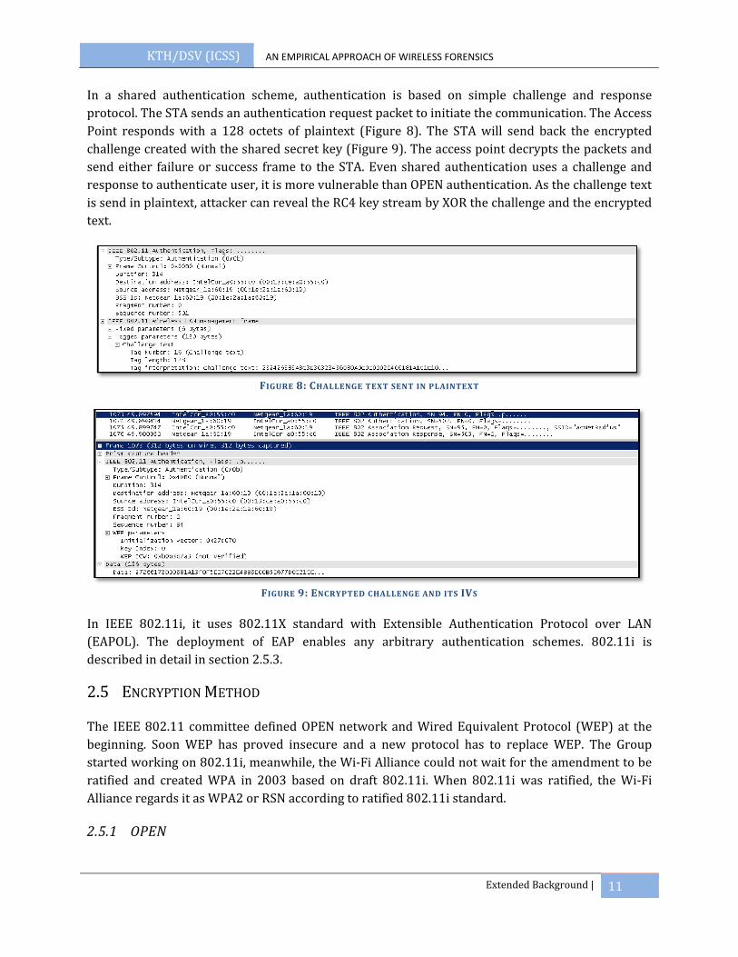
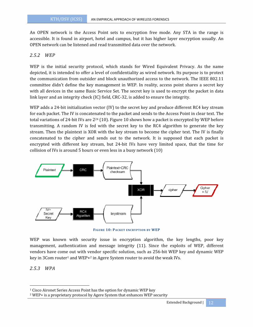
In a shared authentication scheme, authentication is based on simple challenge and response protocol. The STA sends an authentication request packet to initiate the communication. The Access Point responds with a 128 octets of plaintext (Figure 8). The STA will send back the encrypted challenge created with the shared secret key (Figure 9). The access point decrypts the packets and send either failure or success frame to the STA. Even shared authentication uses a challenge and response to authenticate user, it is more vulnerable than OPEN authentication. As the challenge text is send in plaintext, attacker can reveal the RC4 key stream by XOR the challenge and the encrypted text.
FIGURE 8: CHALLENGE TEXT SENT IN PLAINTEXT
FIGURE 9: ENCRYPTED CHALLENGE AND ITS IVS
In IEEE 802.11i, it uses 802.11X standard with Extensible Authentication Protocol over LAN (EAPOL). The deployment of EAP enables any arbitrary authentication schemes. 802.11i is described in detail in section 2.5.3.
2.5 ENCRYPTION METHOD
The IEEE 802.11 committee defined OPEN network and Wired Equivalent Protocol (WEP) at the beginning. Soon WEP has proved insecure and a new protocol has to replace WEP. The Group started working on 802.11i, meanwhile, the Wi‐Fi Alliance could not wait for the amendment to be ratified and created WPA in 2003 based on draft 802.11i. When 802.11i was ratified, the Wi‐Fi Alliance regards it as WPA2 or RSN according to ratified 802.11i standard.
2.5.1 OPEN
KTH/DSV (ICSS) AN EMPIRICAL APPROACH OF WIRELESS FORENSICS
Extended Background | 12
An OPEN network is the Access Point sets to encryption free mode. Any STA in the range is accessible. It is found in airport, hotel and campus, but it has higher layer encryption usually. An OPEN network can be listened and read transmitted data over the network.
2.5.2 WEP
WEP is the initial security protocol, which stands for Wired Equivalent Privacy. As the name depicted, it is intended to offer a level of confidentiality as wired network. Its purpose is to protect the communication from outsider and block unauthorized access to the network. The IEEE 802.11 committee didn’t define the key management in WEP. In reality, access point shares a secret key with all devices in the same Basic Service Set. The secret key is used to encrypt the packet in data link layer and an integrity check (IC) field, CRC‐32, is added to ensure the integrity.
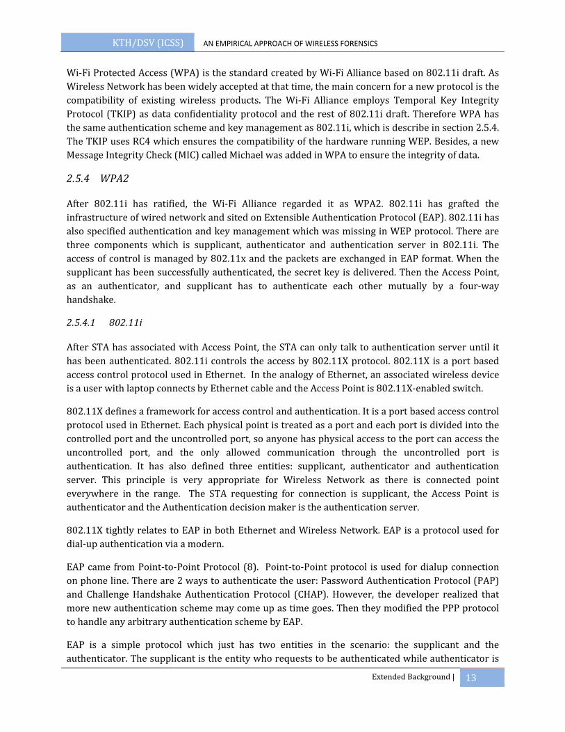
WEP adds a 24‐bit initialization vector (IV) to the secret key and produce different RC4 key stream for each packet. The IV is concatenated to the packet and sends to the Access Point in clear text. The total variations of 24‐bit IVs are 224 (10). Figure 10 shows how a packet is encrypted by WEP before transmitting. A random IV is fed with the secret key to the RC4 algorithm to generate the key stream. Then the plaintext is XOR with the key stream to become the cipher text. The IV is finally concatenated to the cipher and sends out to the network. It is supposed that each packet is encrypted with different key stream, but 24‐bit IVs have very limited space, that the time for collision of IVs is around 5 hours or even less in a busy network (10)
FIGURE 10: PACKET ENCRYPTION BY WEP
WEP was known with security issue in encryption algorithm, the key lengths, poor key management, authentication and message integrity (11). Since the exploits of WEP, different vendors have come out with vendor specific solution, such as 256‐bit WEP key and dynamic WEP key in 3Com router1 and WEP+2 in Agere System router to avoid the weak IVs.
2.5.3 WPA
1 Cisco Aironet Series Access Point has the option for dynamic WEP key 2 WEP+ is a proprietary protocol by Agere System that enhances WEP security
KTH/DSV (ICSS) AN EMPIRICAL APPROACH OF WIRELESS FORENSICS
Extended Background | 13
Wi‐Fi Protected Access (WPA) is the standard created by Wi‐Fi Alliance based on 802.11i draft. As Wireless Network has been widely accepted at that time, the main concern for a new protocol is the compatibility of existing wireless products. The Wi‐Fi Alliance employs Temporal Key Integrity Protocol (TKIP) as data confidentiality protocol and the rest of 802.11i draft. Therefore WPA has the same authentication scheme and key management as 802.11i, which is describe in section 2.5.4. The TKIP uses RC4 which ensures the compatibility of the hardware running WEP. Besides, a new Message Integrity Check (MIC) called Michael was added in WPA to ensure the integrity of data.
2.5.4 WPA2
After 802.11i has ratified, the Wi‐Fi Alliance regarded it as WPA2. 802.11i has grafted the infrastructure of wired network and sited on Extensible Authentication Protocol (EAP). 802.11i has also specified authentication and key management which was missing in WEP protocol. There are three components which is supplicant, authenticator and authentication server in 802.11i. The access of control is managed by 802.11x and the packets are exchanged in EAP format. When the supplicant has been successfully authenticated, the secret key is delivered. Then the Access Point, as an authenticator, and supplicant has to authenticate each other mutually by a four‐way handshake.
2.5.4.1 802.11i
After STA has associated with Access Point, the STA can only talk to authentication server until it has been authenticated. 802.11i controls the access by 802.11X protocol. 802.11X is a port based access control protocol used in Ethernet. In the analogy of Ethernet, an associated wireless device is a user with laptop connects by Ethernet cable and the Access Point is 802.11X‐enabled switch.
802.11X defines a framework for access control and authentication. It is a port based access control protocol used in Ethernet. Each physical point is treated as a port and each port is divided into the controlled port and the uncontrolled port, so anyone has physical access to the port can access the uncontrolled port, and the only allowed communication through the uncontrolled port is authentication. It has also defined three entities: supplicant, authenticator and authentication server. This principle is very appropriate for Wireless Network as there is connected point everywhere in the range. The STA requesting for connection is supplicant, the Access Point is authenticator and the Authentication decision maker is the authentication server.
802.11X tightly relates to EAP in both Ethernet and Wireless Network. EAP is a protocol used for dial‐up authentication via a modern.
EAP came from Point‐to‐Point Protocol (8). Point‐to‐Point protocol is used for dialup connection on phone line. There are 2 ways to authenticate the user: Password Authentication Protocol (PAP) and Challenge Handshake Authentication Protocol (CHAP). However, the developer realized that more new authentication scheme may come up as time goes. Then they modified the PPP protocol to handle any arbitrary authentication scheme by EAP.
EAP is a simple protocol which just has two entities in the scenario: the supplicant and the authenticator. The supplicant is the entity who requests to be authenticated while authenticator is

KTH/DSV (ICSS) AN EMPIRICAL APPROACH OF WIRELESS FORENSICS
Extended Background | 14
the one doing authentication. EAP has defined four categories of messages: Request, Response, Success and Failure. Request is the packet sent from authenticator to supplicant. Response is the response from the supplicant to the authenticator. Then either a Success or Failure packet is sent from authenticator to indicate authentication result.
As to use EAP in Wireless LANs, the EAP packet has to be wrapped with something to pass between supplicant and authenticator. It is called EAP over LAN (EAPOL). Four types of EAPOL were defined for the communication between supplicant (STA) and authenticator (AP) (12):
• EAPOL‐packet: a container for transporting EAP packet across LAN • EAPOL‐start: a packet from the supplicant to inform the authenticator that it wants to
authenticate • EAPOL‐logoff: a packet from the supplicant to inform the authenticator that it disconnects
from the network • EAPOL‐key: packets to exchange the encryption key once the supplicant authenticated.
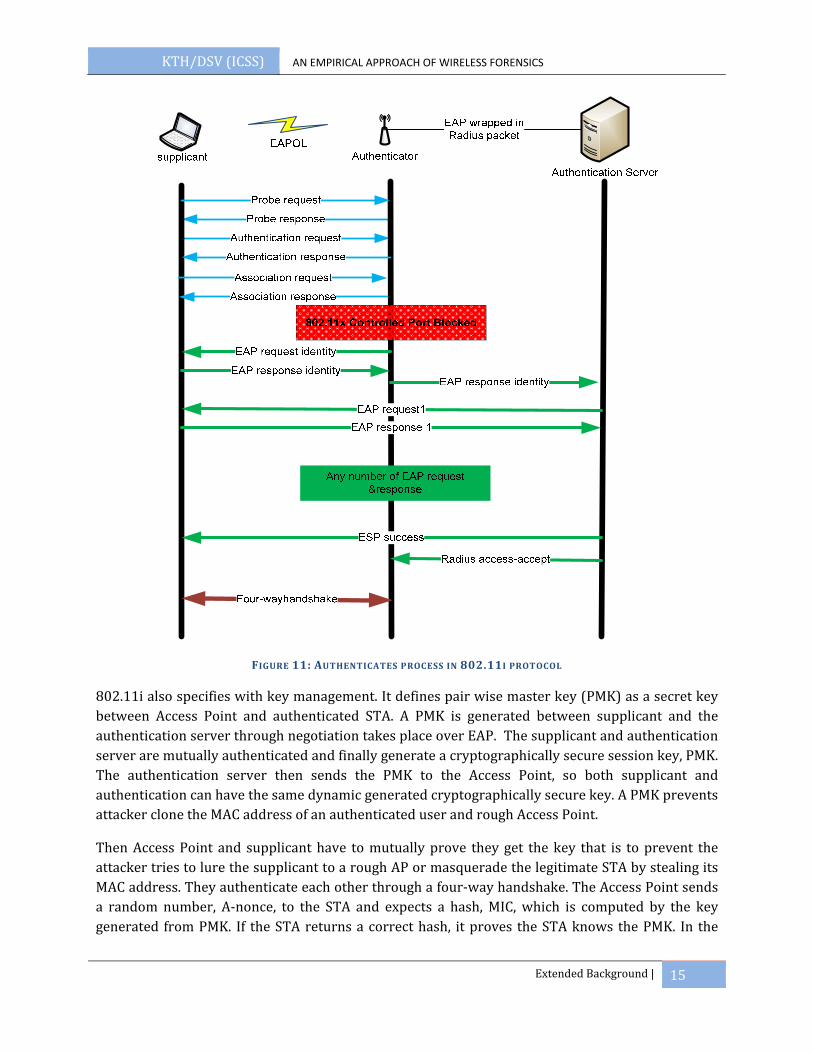
Between the communication of authentication (AP) and authentication server, 802.11i used Remote Access Dial‐In User Service (RADIUS) as a mean to transport the EAP packet from Access Point to authentication server. In three‐tier architecture, the Access Point is no longer handling the authentication scheme. The Access Point receives EAP packets from the supplicant (STA), wraps them to RADIUS packet and sends to Authentication server. When the Access Point receives a RADIUS packet from the authentication server, it will convert the RADIUS packet to EAP packets and forward to the supplicant. Until the Access Point gets an Access‐accept packet, it will know the supplicant has been authenticated and let the STA connect to the network. Figure 11 shows how the STA associates with the Access Point, authenticates mutually with authentication server, and then derives the keys by a four way handshake.
KTH/DSV (ICSS) AN EMPIRICAL APPROACH OF WIRELESS FORENSICS
Extended Background | 15
FIGURE 11: AUTHENTICATES PROCESS IN 802.11I PROTOCOL
802.11i also specifies with key management. It defines pair wise master key (PMK) as a secret key between Access Point and authenticated STA. A PMK is generated between supplicant and the authentication server through negotiation takes place over EAP. The supplicant and authentication server are mutually authenticated and finally generate a cryptographically secure session key, PMK. The authentication server then sends the PMK to the Access Point, so both supplicant and authentication can have the same dynamic generated cryptographically secure key. A PMK prevents attacker clone the MAC address of an authenticated user and rough Access Point.
Then Access Point and supplicant have to mutually prove they get the key that is to prevent the attacker tries to lure the supplicant to a rough AP or masquerade the legitimate STA by stealing its MAC address. They authenticate each other through a four‐way handshake. The Access Point sends a random number, A‐nonce, to the STA and expects a hash, MIC, which is computed by the key generated from PMK. If the STA returns a correct hash, it proves the STA knows the PMK. In the

KTH/DSV (ICSS) AN EMPIRICAL APPROACH OF WIRELESS FORENSICS
Extended Background | 16
same way, the STA sends a random number, S‐nonce, to the Access Point and expects a correct hash. A complete 4 way handshake is illustrated in Figure 12.
FIGURE 12: A FOURWAY HANDSHAKE
802.11i has defined a comprehensive way for key distribution and hierarchy, which is independent from the encryption protocol. The four way handshake is not just a proof that both Access Point and STA have the PMK, but also a variant to generate the PTK. There are four PTK key (Figure 13). PTK is recomputed when STA re‐associated or session expires to ensure the PTK is unique.
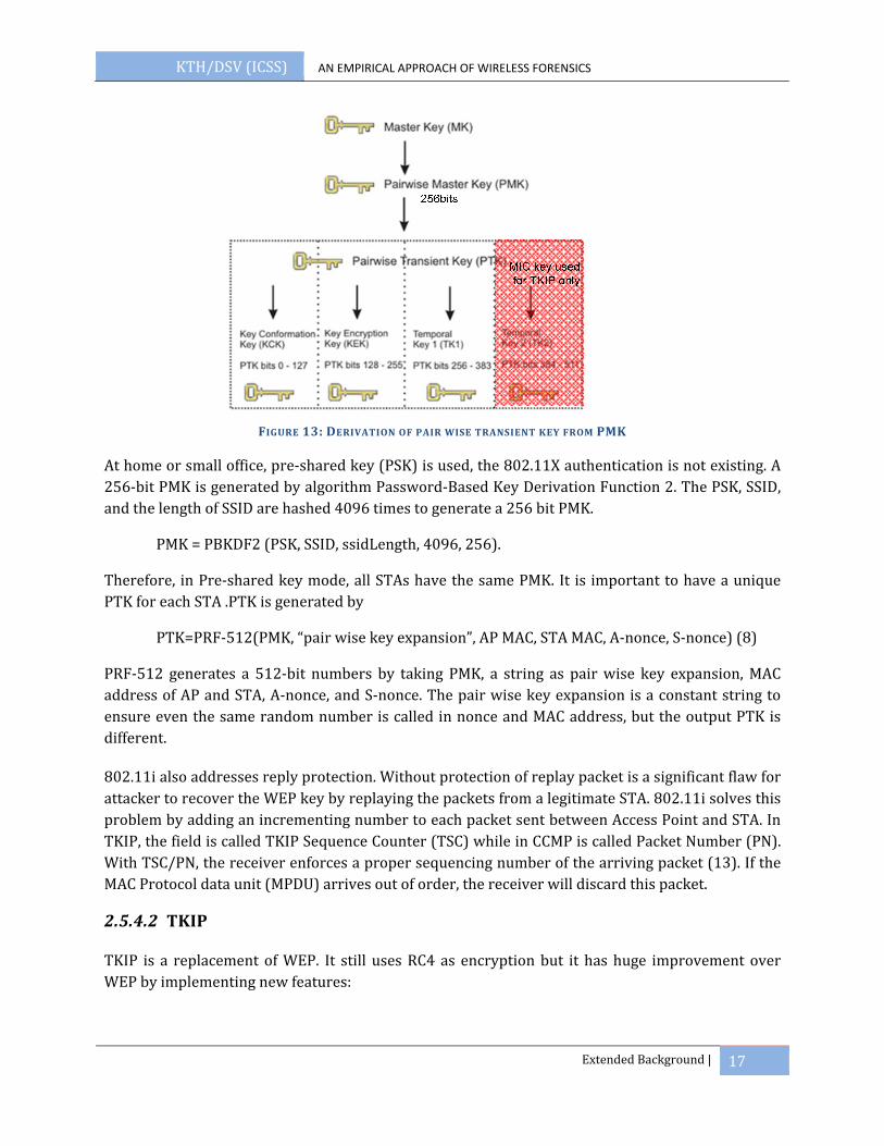
• EAPOL‐Key Encryption Key (KEK) ‐ AP uses this key to encrypt additional data sent (in the 'Key Data' field) to the STA (for example, the RSN IE or the GTK)
• EAPOL‐Key Confirmation Key (KCK)– Used to compute MIC on WPA EAPOL Key message • Temporal Key (TK) – Used to encrypt/decrypt unicast data packets • Michael MIC Authenticator Tx Key – Used to compute MIC on unicast data packets
transmitted by the AP, only used in TKIP (12)
KTH/DSV (ICSS) AN EMPIRICAL APPROACH OF WIRELESS FORENSICS
Extended Background | 17
FIGURE 13: DERIVATION OF PAIR WISE TRANSIENT KEY FROM PMK
At home or small office, pre‐shared key (PSK) is used, the 802.11X authentication is not existing. A 256‐bit PMK is generated by algorithm Password‐Based Key Derivation Function 2. The PSK, SSID, and the length of SSID are hashed 4096 times to generate a 256 bit PMK.
PMK = PBKDF2 (PSK, SSID, ssidLength, 4096, 256).
Therefore, in Pre‐shared key mode, all STAs have the same PMK. It is important to have a unique PTK for each STA .PTK is generated by
PTK=PRF‐512(PMK, “pair wise key expansion”, AP MAC, STA MAC, A‐nonce, S‐nonce) (8)
PRF‐512 generates a 512‐bit numbers by taking PMK, a string as pair wise key expansion, MAC address of AP and STA, A‐nonce, and S‐nonce. The pair wise key expansion is a constant string to ensure even the same random number is called in nonce and MAC address, but the output PTK is different.
802.11i also addresses reply protection. Without protection of replay packet is a significant flaw for attacker to recover the WEP key by replaying the packets from a legitimate STA. 802.11i solves this problem by adding an incrementing number to each packet sent between Access Point and STA. In TKIP, the field is called TKIP Sequence Counter (TSC) while in CCMP is called Packet Number (PN). With TSC/PN, the receiver enforces a proper sequencing number of the arriving packet (13). If the MAC Protocol data unit (MPDU) arrives out of order, the receiver will discard this packet.
2.5.4.2 TKIP
TKIP is a replacement of WEP. It still uses RC4 as encryption but it has huge improvement over WEP by implementing new features:
KTH/DSV (ICSS) AN EMPIRICAL APPROACH OF WIRELESS FORENSICS
Extended Background | 18
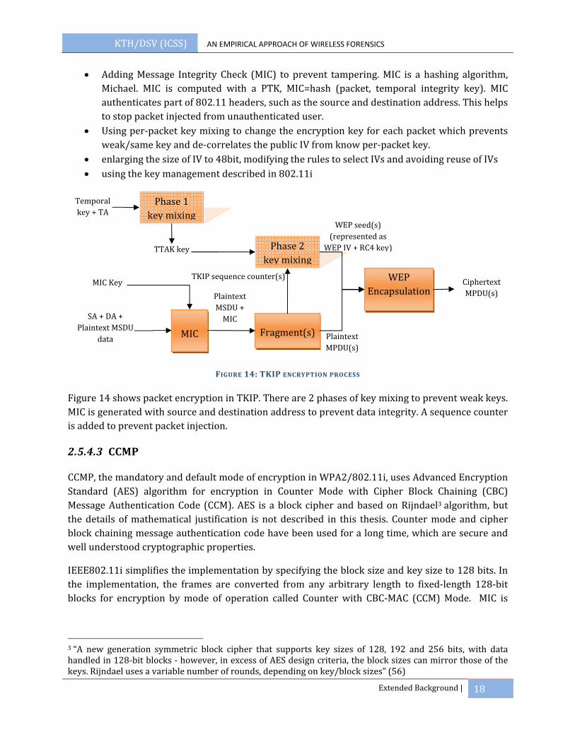
• Adding Message Integrity Check (MIC) to prevent tampering. MIC is a hashing algorithm, Michael. MIC is computed with a PTK, MIC=hash (packet, temporal integrity key). MIC authenticates part of 802.11 headers, such as the source and destination address. This helps to stop packet injected from unauthenticated user.
• Using per‐packet key mixing to change the encryption key for each packet which prevents weak/same key and de‐correlates the public IV from know per‐packet key.
• enlarging the size of IV to 48bit, modifying the rules to select IVs and avoiding reuse of IVs • using the key management described in 802.11i
FIGURE 14: TKIP ENCRYPTION PROCESS
Figure 14 shows packet encryption in TKIP. There are 2 phases of key mixing to prevent weak keys. MIC is generated with source and destination address to prevent data integrity. A sequence counter is added to prevent packet injection.
2.5.4.3 CCMP
CCMP, the mandatory and default mode of encryption in WPA2/802.11i, uses Advanced Encryption Standard (AES) algorithm for encryption in Counter Mode with Cipher Block Chaining (CBC) Message Authentication Code (CCM). AES is a block cipher and based on Rijndael3 algorithm, but the details of mathematical justification is not described in this thesis. Counter mode and cipher block chaining message authentication code have been used for a long time, which are secure and well understood cryptographic properties.
IEEE802.11i simplifies the implementation by specifying the block size and key size to 128 bits. In the implementation, the frames are converted from any arbitrary length to fixed‐length 128‐bit blocks for encryption by mode of operation called Counter with CBC‐MAC (CCM) Mode. MIC is
3 “A new generation symmetric block cipher that supports key sizes of 128, 192 and 256 bits, with data handled in 128‐bit blocks ‐ however, in excess of AES design criteria, the block sizes can mirror those of the keys. Rijndael uses a variable number of rounds, depending on key/block sizes” (56)
Phase 1 key mixing
Temporal key + TA
TTAK key Phase 2 key mixing
MIC Key
SA + DA + Plaintext MSDU
data
TKIP sequence counter(s)
Plaintext MSDU + MIC
Plaintext MPDU(s)
WEP seed(s) (represented as
WEP IV + RC4 key)
Fragment(s)
MIC
WEP Encapsulation
Ciphertext MPDU(s)

KTH/DSV (ICSS) AN EMPIRICAL APPROACH OF WIRELESS FORENSICS
Extended Background | 19
calculated by AES in CBC‐MAC mode and appended to the MPDU4 for transmission. AES in counter mode is used to encrypt the MPDU and MIC computed.
In CCMP, 3 PTK is generated. Encryption and data integrity use the same temporal key. Figure 15 shows encryption packed by CCMP.
FIGURE 15: CCMP ENCRYPTION BLOCK, FROM (12)
2.6 COMPARISON OF WEP, WPA AND 802.11I
Most of the routers in the market have implemented WEP, TKIP and AES. There are also options for combination like TKIP and AES or WEP and TKIP to allow different hardware. Besides, some terms like WPA, WPA2, 802.11i, RSN and TSN are confused in the public.
802.11i is an amendment standard to 802.11, which defines a robust security network (RSN) and its medium access control security enhancement. Wi‐Fi alliance implements part 802.11i and regards it as WPA. WPA2 is the implementation of full 802.11i standard in Wi‐Fi certificated product. WPA allows WEP and TKIP as encryption protocols, while WPA2 chooses AES as default encryption protocol, but also allows TKIP. However most WPA2 products allow TKIP in WPA2 also allow TKIP connection from WPA certificated product. When this happens, it is not a RSN network anymore as the mandatory element of 802.11i ‐ the robust security network association is missing. It is called a transition security network (TSN). David, Andrew and Mark give a clearly definition of RSN and TSN. (11) “A RSN can be identified by the indication in the RSN Information Element of Beacon frames that the group cipher suite specified is not WEP.” In short, WPA2 requires RSN four‐way handshake, RSN Information Element, CCMP implemented and WEP not allowed. In the contrast, WPA requires four‐way handshake, WPA element or none, CCMP optional and WEP allowed. The RSN information element negotiates the type of encryption used and force the STA to use a more advanced protocol. The difference of WEP, WPA and WPA2 is summarized in Table 2.
4 MAC Protocol Data Unit, which is the fragmented unit of MAC Service Data Unit

KTH/DSV (ICSS) AN EMPIRICAL APPROACH OF WIRELESS FORENSICS
Extended Background | 20
Table 2: Comparison of WEP, WPA and RSN Security Protocol Features of Mechanism WEP WPA WPA2 Encryption Cipher Mechanism
RC4 (VulnerableIV usage)
RC4/TKIPCCMP optional
AES/CCMP defaultTKIP/CCMP optional
Encryption Key Size 40 bits 128 bits 128bits Encryption Key Per Packet Concatenated Mixed NA Encryption Key Management None 802.11x 802.11x Encryption Key Change None For each packet No need IV Size 24 bits 48 bits 48 bits Authentication Open /shared 802.11x –EAP 802.11x –EAPData Integrity CRC32‐ICV MIC (Michael) CCM Header Integrity None MIC (Michael) CCM Replay Attack Prevention None TKIP Sequence
Counter Packet Number
Compatibility WEP WEP/TKIP TKIP/CCMPRSN No No RSN IE & RSNAAd‐hoc support WEP WEP WPA/WPA2WEP allowed Yes Yes No RSN network No TSN RSN
2.7 WIRELESS FORENSICS
Computer forensics, also known as digital forensics, is techniques employed in legal cases for analysis of computer systems, recovery of data in hardware failure, analysis of computer system after a break in, information or evidence gathering for the purpose of debugging, performance optimization and reverse engineering (14). The U.S Department of Justice released Forensic Examination of Digital Evidence: A Guide for Law Enforcement where described three procedural principles in general forensic:
• Actions taken to secure and collect digital evidence should not affect the integrity of that evidence.
• Persons conducting an examination of digital evidence should be trained for that purpose. • Activity relating to the seizure, examination, storage, or transfer of digital evidence should be
documented, preserved, and available for review (15).
The basic steps in computer forensics involve preparation of investigator, data collection, examination, analysis and reporting. Wireless forensics is a small branch of computer forensics and implies the same rules as in computer forensics, having the process to identify, preserve and analyze the evidence. However, wireless forensics is different from computer forensics in technologies and it is more than tracing through the ISP as in network forensics. Specifically, wireless forensics is “to provide the methodology and tools required to collect and analyze (wireless) network traffic that can be presented as valid digital evidence in a court of law. The evidence collected can correspond to plain data or, with the broad usage of VoiceoverIP (VoIP) technologies, especially over wireless, can include voice conversations (16).”
KTH/DSV (ICSS) AN EMPIRICAL APPROACH OF WIRELESS FORENSICS
Extended Background | 21
The Digital Forensics Research Workshop (DFRWS) defines digital forensic science as “The use of scientifically derived and proven methods toward the preservation, collection, validation, identification, analysis, interpretation, documentation and presentation of digital evidence derived from digital sources for the purpose of facilitating or furthering the reconstruction of events found to be criminal, or helping to anticipate unauthorized actions shown to be disruptive to planned operations.” They have identified seven processes which begin from identification, preservation, collection, examination, analysis, presentation and decision (1).
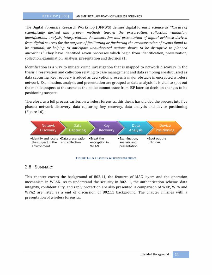
Identification is a way to initiate crime investigation that is mapped to network discovery in the thesis. Preservation and collection relating to case management and data sampling are discussed as data capturing. Key recovery is added as decryption process is major obstacle in encrypted wireless network. Examination, analysis and presentation are grouped as data analysis. It is vital to spot out the mobile suspect at the scene as the police cannot trace from ISP later, so decision changes to be positioning suspect.
Therefore, as a full process carries on wireless forensics, this thesis has divided the process into five phases: network discovery, data capturing, key recovery, data analysis and device positioning (Figure 16).
FIGURE 16: 5 PHASES IN WIRELESS FORENSICS
2.8 SUMMARY
This chapter covers the background of 802.11, the features of MAC layers and the operation mechanism in WLAN. As to understand the security in 802.11, the authentication scheme, data integrity, confidentiality, and reply protection are also presented. a comparison of WEP, WPA and WPA2 are listed as a end of discussion of 802.11 background. The chapter finishes with a presentation of wireless forensics.
Netowk Discovery
•Identify and locate the suspect in the environment
Data Capturing
•Data preservation and collection
Key Recovery
•Break the encryption in WLAN
Data Analysis
•Examination, analysis and presentation
Device Positioning
•Spot out the intruder
KTH/DSV (ICSS) AN EMPIRICAL APPROACH OF WIRELESS FORENSICS
Vulnerability of WLAN | 22
3 VULNERABILITY OF WLAN
The difference between wired network and wireless network is everyone in the range can access the network in wireless Network. However in wired network, only physically connect devices can access the network. Wireless Network is vulnerable in nature because of radio frequency. Besides, wireless network has faced serious security challenges in protocols. In this chapter, the security issues regarding WLAN and its security protocols are discussed.
3.1 WIRELESS LAN IS VULNERABLE IN NATURE
Wireless Network uses radio frequency which is a broadcast technology as a medium of transmission. The transmission of signal to or from any STA can be received by all people in the range. It is important to have a secure enough protocol deployed in Wireless Network. However, no matter which security protocol is using, WLAN is vulnerable when STA associates with Access Point and in MAC layer.
IEEE802.11 has defined management packet to establish the communication with the Access Point. However, all management packets are unencrypted and unauthenticated. Without protection in management frame, attackers can send out Deauthentication or Disassociation frame to block the access of a legitimate user, which is called Denial of Service (DoS) attack. Although Dos attack doesn’t cause serious damage, but it affects the application performance critically, especially for delay sensitive application, such as VoIP and video. The control frames are also unencrypted and unauthenticated. The attacker can send RTS and waits for CTS to jam the network.
Wireless Network is also vulnerable to Man‐in‐the‐Middle Attack. Due to the fact STA tends to associate with the Access Point offering stronger signal, a rouge AP can be put closer to the victim and imitate to be the legitimate AP. After the STA connects to the rouge AP, the attack can perform any malicious attack they intent to. If the attacker has access to the encryption key, he can delete, add or modify the data. Another similar attack is called evil twin attack. Evil twin attack spoofs the MAC address and configuration of the legitimate Access point, and tires to forward the STAs to the fake login page to steal user’s authentication credentials.
3.2 FLAWS IN WEP
WEP had serious flaws in design and was broken by Fluhrer, Mantin, and Shamir (FMS) in 2001 (17). Further attacks were released afterwards which decrypts the data frames faster and faster, such as chopchop, Korek and PTW attack which are discussed in section 5.1.
WEP has been discovered serious weakness in cryptography which is summarized as follows:

KTH/DSV (ICSS) AN EMPIRICAL APPROACH OF WIRELESS FORENSICS
Vulnerability of WLAN | 23
• Limited space of IVs: 24‐bit IVs are used as a seed to generate the key stream which is inadequate in combination and the usage of key stream repeatedly which brings cryptanalysis attack. Besides, the 24bits IVs are concatenated to the packet in clear text
• Insecure integrity check CRC‐32 checksum: the nature of CRC32 is linear which is not cryptographically strong (18). The attacker may tamper any arbitrary bits in the encrypted message and adjust the checksum to result a valid message.
• Weakness of key scheduling algorithm of RC4: in the paper of Fluhrer (17), he has described a large number of weak keys are generated in RC4 algorithm, which is capable of determining the key bits and possible to reconstruct the secret key in WEP.
• Weak Authentication: shared authentication allows attacker to sniff the change of handshake. From the plaintext and cipher text, he can extract the key stream and use to forge an authentication.
3.3 VULNERABILITY OF WPA
802.11i has not yet proved any exploit until now. However, WPA pre‐shared key suffers from dictionary attack. “Dictionary attack is a technique for defeating a cipher or authentication mechanism by trying to determine its decryption key or passphrase by search likely possibilities (19).” WPA‐PSK is vulnerable during the four way handshake exchange. When a complete handshake is captured passively, the attacker can run offline dictionary attack to recover the key and decrypt entire session. The success of dictionary attack is because of human being. People tend to choose a password that is familiar and easy to remember.
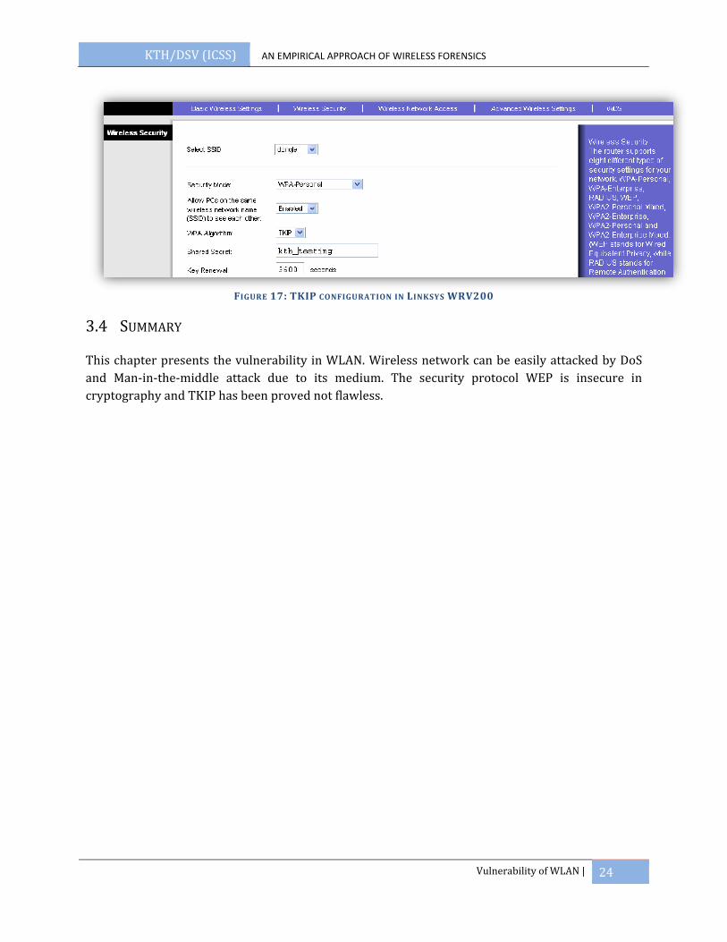
Furthermore, Martin and Erik (20) have explored the flaw in TKIP. Under the condition that IPv4 is used, most byte of the IP address is known, key renewal is 3600 second, which is the default value in AP (Figure 17), and with IEEE802.11e is enabled; the attacker can decrypt traffic encrypted by TKIP in a chopchop attack manner. Chopchop attack is depicted in section 5.1.2. The attacker can capture an ARP packet, which can be easily identified from the length. Even ARP packet is encrypted, the attacker has known most of the plaintext of this packet, except last byte of the destination and source address, MIC and ICV are unknown. By using these facts and WEP chopchop attack, it allows attacker to send 7‐15 packets to the network. When the attack is successful, the attacker can retrieve the plaintext of one packet, as well as know the key stream and MIC code of the session. This attack has implemented in open source software, called tkiptun‐ng in Aircrack‐ng suite (21).
KTH/DSV (ICSS) AN EMPIRICAL APPROACH OF WIRELESS FORENSICS
Vulnerability of WLAN | 24
FIGURE 17: TKIP CONFIGURATION IN LINKSYS WRV200
3.4 SUMMARY
This chapter presents the vulnerability in WLAN. Wireless network can be easily attacked by DoS and Man‐in‐the‐middle attack due to its medium. The security protocol WEP is insecure in cryptography and TKIP has been proved not flawless.

KTH/DSV (ICSS) AN EMPIRICAL APPROACH OF WIRELESS FORENSICS
Network Discovery and Data Capturing | 25
4 NETWORK DISCOVERY AND DATA CAPTURING
This chapter suggests the first phase of wireless forensics is network discovery to see if the suspected the networks can be found. After the network is identify, forensics examiners can capture the data traffic pass through. As network discovery provides the network information in the field which is tied tightly with data capture, these two phases are discussed in the same chapter.
802.11b/g is operating in 2.4GHz bands, so the discovery and capture modules has to support 2.4GHz and its supporting channels. For a home user, usually they have a single Access Point with a signal operating channel. However, in the enterprise environment, there is multiple Access Points bridged together. As to avoid interference, they are operating in different channels. A discovery and capture modules should able to listen to all of the channels simultaneously. For example, in 802.11b/g, which has 14 channels, so 15 radio devices are required. One radio card is for listening continuously and the other 14 radio cards are assigned for capturing to different channels respectively (22).
4.1 WIRELESS LAN DISCOVERY
In the field, it is necessary to know what networks are around, especially in some countries which don’t allow listen to all the channels. There are 2 ways to discover the networks: active scanning and passive scanning which means radio frequency monitoring (RFMON) (23).
In active scanning, the system sends out probe request periodically and waits for probe response from the Access Point in the range. The system can send out a broadcast probe request, which is like “Hello, is anyone there?” or a targeted probe request, which is like “Network SSID, are you there?” Beacons can also used to find networks. Access Point sends out 10 Beacon frames per second in general. Beacon contains information same as probe response, such as SSID, source and destination addresses, BSSID, support rate… The drawback of active scanning is the scanner may not see other wireless traffic except probe request, probe response and beacons.
Active scanning is not the best way of detecting networks as some Access Points can be configured not to response to probe request. Besides, scanner sends out probe request revealing its existence which is detectable by Intrusion Detection System.
Passive scanning or RFMON is better than active scanning. It doesn’t send any packet to the air, but listen to all the traffic on a given channel and analyze them. Setting a wireless card in monitor mode, the card will just receive all the packets in the range. This is similar as putting an Ethernet Card into promiscuous mode. However, in wireless network, the wireless card is able to see all the traffic in the spectrum, such 2.4GHz. When the wireless card sets to hop around all the channels in 802.11b/g, all networks in different channels are discovered. The scanner reads the packets from the wireless card, analyzes them and update to the user. The scanner is interested in Probe request, Probe response, Association request/re‐association request, Beacons and Data packet. All these

KTH/DSV (ICSS) AN EMPIRICAL APPROACH OF WIRELESS FORENSICS
Network Discovery and Data Capturing | 26
packets give information about the network, such as MAC address, SSID, channel, operating speed, type of network, encryption, signal to noise ratio and received signal strength index (RSSI).
When a data packet/beacon/probe response/association request is captured with a new BSSID, the scanner will report a new Access Point found. When the corresponding SSID, channel, encryption… are found, this information will tie to that BSSID. Therefore, a network mapping BSSID with associated STAs are presented.
There are plenty of similar open source tools running on RFMON to discover the networks, for example, NetStumbler and Kismet. Figure 18 shows the network discovery result found by airodump‐ng. All information, including, BSSID, ESSID, signal strength, channel number, encryption method, authentication method, associated STAs, packets captured and beacons frames, are shown.
FIGURE 18: NETWORK DISCOVERY BY AIRODUMPNG
4.1.1 DISCOVERY OF HIDDEN NETWORK
When Access Point is configured to hidden or cloaked, it doesn’t respond to broadcast probe requests and transmit their SSID in beacons. The SSID is set to NULL in the beacon frame. To reveal the SSID of the network, the scanner can keep on logging the traffic. Whenever a STA connect to Access Point, there is probe response or association or re‐association frame transmitting between. Therefore, the scanner can wait for the probe request when a legitimated STA associates with the Access Point. Moreover, the scanner can send a Deauthentication packet to an associated STA to force it to re‐associate (16), but this active sending packet exposes the existing of scanner.
4.1.2 DISCOVERY OF ADHOC NETWORK
Ad‐hoc network can be discovered by Basic Service Set Identifier (BSSID). In infrastructure mode, the BSSID is the MAC address of the Access point, which is unique to identify the network. A MAC address consists of 3 bytes of Organizationally Unique Identifier (OUI) and 3‐bytes of Network Interface Controller (NIC) Specific. OUI is its manufacturer identifier and NIC is a unique string assigned by the manufacturer. In the most significant byte, the second least bit decides whether this

KTH/DSV (ICSS) AN EMPIRICAL APPROACH OF WIRELESS FORENSICS
Network Discovery and Data Capturing | 27
address is locally administrated address or OUI enforced address. If it is locally administered, it sets to 1. If it is OUI enforced, it sets to 0. In infrastructure mode, the second least bit of the most significant bye sets to 0. The format of MAC address is shown in Figure 19.
FIGURE 19: MAC ADDRESS ILLUSTRATION
In an Ad‐hoc network, the BSSID is a 46‐bit randomly generated number. The second least bit is set to 1 and the last least bit sets to 0. For example, the first most significant byte is 00000010. The MAC address is 02‐xx‐xx‐xx‐xx‐xx, which represent this is Ad‐hoc network.
4.2 A SURVEY OF WIRELESS NETWORKS IN STOCKHOLM CITY
As to understand the network discovery in practice, a war driving was performed to have an overview of wireless networks around Stockholm city in May 2008. The war driving machine is configured as follows
TABLE 3: WAR DRIVING SYSTEM CONFIGURATION
Hardware: A laptop with dual core 2
OS: Linux Fedora 6
Wireless Card: Atheros chipset wireless card which is set in monitor mode
Antenna: 6dBi Omnidirectional antenna
The range of detected networks can be increased dramatically by placing a stronger antenna. Omnidirectional antenna is always a good choice in an unknown environment, but the directional antenna gives stronger signal if the direction of suspects is identified. In war driving, an omnidirectional antenna is a better choice. The route is driving around in zone 1 of Stockholm city (Figure 20). Around one hour, 2243 of wireless devices were found and 1437 of them are Access Point. Wireless network has been widely deployed in Stockholm.

KTH/DSV (ICSS) AN EMPIRICAL APPROACH OF WIRELESS FORENSICS
Network Discovery and Data Capturing | 28
FIGURE 20: AREA OF WAR DRIVING IN STOCKHOLM
The war driving result is analyzed in terms of channel, encryption method and authentication method. From the result, it shows people don’t care about the security of wireless network much. It is a normal phenomenon people simply don’t think their data traffic is valuable, which makes these network as a mean for digital crime.
Figure 21 shows the channel that used in WLAN. The most widely used channels are 1, 6 and 11. Almost two‐third is using 6 and 11. Channel 14 is not allowed in Europe, it can be a reason for suspecting. Channel ‐1 means the wireless card doesn’t know support the frequency reported. For example, the wireless cards 802.11b/g doesn’t support the frequency from 802.11a or 802.11n.
FIGURE 21: WAR DRIVING RESULT –CHANNELS DISTRIBUTION
It is surprised that the most commonly used encryption method is still WEP even after it has been broken by key recovery tools for 6 years. Figure 22 shows about one‐third networks are using WEP.
0
50
100
150
200
250
300
350
400
7
253
3752
35 26
400
31 41 49 47
387
9
61
2
No. of networks
Channel
Distribution of Channels
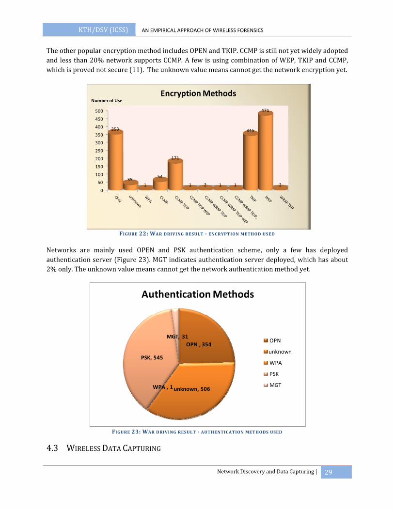
KTH/DSV (ICSS) AN EMPIRICAL APPROACH OF WIRELESS FORENSICS
Network Discovery and Data Capturing | 29
The other popular encryption method includes OPEN and TKIP. CCMP is still not yet widely adopted and less than 20% network supports CCMP. A few is using combination of WEP, TKIP and CCMP, which is proved not secure (11). The unknown value means cannot get the network encryption yet.
FIGURE 22: WAR DRIVING RESULT ENCRYPTION METHOD USED
Networks are mainly used OPEN and PSK authentication scheme, only a few has deployed authentication server (Figure 23). MGT indicates authentication server deployed, which has about 2% only. The unknown value means cannot get the network authentication method yet.
FIGURE 23: WAR DRIVING RESULT AUTHENTICATION METHODS USED
4.3 WIRELESS DATA CAPTURING
0
50
100
150
200
250
300
350
400
450
500
353
351
54
171
1 2 1 1
345
471
2
Number of UseEncryption Methods
OPN , 354
unknown, 506WPA , 1
PSK, 545
MGT, 31
Authentication Methods
OPN
unknown
WPA
PSK
MGT

KTH/DSV (ICSS) AN EMPIRICAL APPROACH OF WIRELESS FORENSICS
Network Discovery and Data Capturing | 30
Data capturing is to intercept all traffic pass through the target, which is the second phase in wireless forensics. All supporting channels should be captured. Benjamin (24)states the only way to identify all related devices is to analyze the wireless spectrum and protocol themselves. All the information can be extracted from the capturing that is crucial for the forensic investigator to determinate the devices and wireless network. This information includes ESSID, encryption method, channel, MAC address for Access Point and connected STA, and the approximate coordination of Access Point. This information can be seized from the header of wireless frames with proper configuration in the wireless cards. The configuration is different in different card, which depends on the supporting drivers in Linux. Atheros is most popular chipset running in Linux, as the card can be easily installed and configured with the driver offered by Madwifi (25).
Raul (22) has listed the requirement and best practice for wireless forensics tools design. The capturing system should have 15 radio components for 802.11b/g, GPS for timestamps and outdoor location capabilities as evidence, passively capturing only, external antenna, remote control of system for safety reason, enable prism monitor header or AVS WLAN header (depends on the different driver) and standard packet Capture (PCAP) format associated with libpcap library.
As to capture the traffic, the wireless cards have to configure to RFMON mode and assign a specific channel for each card. There are many open sources wireless traffic capturing tools running on Linux OS. Tshark (26) is one of popular tools running in Linux and Wireshark is the version under Window (27).
In capturing, the throughput and data loss should be considered. Wireless network has 3 types of data frame: data, management and control. The management and control packet adds a lot of overhead in the communication. In the hardware aspect, the wireless device should be able to render the maximum throughput of all the channels. Theoretically, 802.11g network with 14 channels are capturing simultaneously, the throughput is 14x54Mbps (756 Mbps) (22).
4.4 DATA CAPTURING PERFORMANCE TEST
There is a question how far the capturing tool should put away from the suspected network. It is suggested to stand as close as to the target, but in reality, the capturing tool should put as far as from the target to be covert. How far the capturing tool should placed but still good enough to capture all the data traffic? An experiment has performed to measure the loss of data in different signal strengths received.
This experiment aims to have an understanding of the packet loss in terms of signal strength received. It gives an overview to a forensic examiner how far should stay away from suspect and still have strong enough signal to collect the evidence.
The wireless network setup consists of one Asus WL‐530 802.11g Access Point and an associated STA A. Another laptop B with Atheros chipset wireless card which sets in monitor mode is the capturing tool (Figure 24). The experiment has to perform three times with scenario A, B and C.

KTH/DSV (ICSS) AN EMPIRICAL APPROACH OF WIRELESS FORENSICS
Network Discovery and Data Capturing | 31
FIGURE 24: EXPERIMENT SETUP FOR DATA CAPTURING PERFORMANCE TEST
A 13MB text file is uploaded to skydrive.live.com as a testing file. In each scenario, STA A will try to download the text file from the skydrive.live.com. The capture tool, Laptop B, will stay in different place according to the adjustment of signal strength received from Asus Access Point and capture the downloading. Three types of signal strengths are defined and calibrated in both window and Linux.
TABLE 4: CALIBRATION OF SIGNAL STRENGTH FOR DATA CAPTURING
Good: Linux: Signal strength received (RSSI) greater than 30 in airodump‐ng Windows: Wireless Zero Configuration indicates Good signal strength
Fair: Linux: Signal strength received (RSSI) is 15 ±5 in airodump‐ng. Windows: Wireless Zero Configuration indicates Fair signal strength
Weak: Linux: Signal strength received (RSSI) is less than 10 (average 6) in airodump‐ngWindows: Wireless Zero Configuration indicates Weak signal strength
After Laptop B has adjusted the location based on the calibration defined in Table 4, it runs airodump‐ng and captures that network. STA A starts downloading the file and the capturing stops 5 seconds after downloading finished. The capture file is compared with the original one and the numbers of words are counted as a measurement.
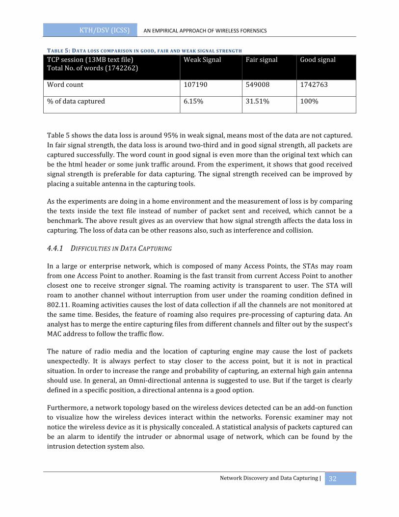
KTH/DSV (ICSS) AN EMPIRICAL APPROACH OF WIRELESS FORENSICS
Network Discovery and Data Capturing | 32
TABLE 5: DATA LOSS COMPARISON IN GOOD, FAIR AND WEAK SIGNAL STRENGTH
TCP session (13MB text file) Total No. of words (1742262)
Weak Signal Fair signal Good signal
Word count 107190 549008 1742763
% of data captured 6.15% 31.51% 100%
Table 5 shows the data loss is around 95% in weak signal, means most of the data are not captured. In fair signal strength, the data loss is around two‐third and in good signal strength, all packets are captured successfully. The word count in good signal is even more than the original text which can be the html header or some junk traffic around. From the experiment, it shows that good received signal strength is preferable for data capturing. The signal strength received can be improved by placing a suitable antenna in the capturing tools.
As the experiments are doing in a home environment and the measurement of loss is by comparing the texts inside the text file instead of number of packet sent and received, which cannot be a benchmark. The above result gives as an overview that how signal strength affects the data loss in capturing. The loss of data can be other reasons also, such as interference and collision.
4.4.1 DIFFICULTIES IN DATA CAPTURING
In a large or enterprise network, which is composed of many Access Points, the STAs may roam from one Access Point to another. Roaming is the fast transit from current Access Point to another closest one to receive stronger signal. The roaming activity is transparent to user. The STA will roam to another channel without interruption from user under the roaming condition defined in 802.11. Roaming activities causes the lost of data collection if all the channels are not monitored at the same time. Besides, the feature of roaming also requires pre‐processing of capturing data. An analyst has to merge the entire capturing files from different channels and filter out by the suspect’s MAC address to follow the traffic flow.
The nature of radio media and the location of capturing engine may cause the lost of packets unexpectedly. It is always perfect to stay closer to the access point, but it is not in practical situation. In order to increase the range and probability of capturing, an external high gain antenna should use. In general, an Omni‐directional antenna is suggested to use. But if the target is clearly defined in a specific position, a directional antenna is a good option.
Furthermore, a network topology based on the wireless devices detected can be an add‐on function to visualize how the wireless devices interact within the networks. Forensic examiner may not notice the wireless device as it is physically concealed. A statistical analysis of packets captured can be an alarm to identify the intruder or abnormal usage of network, which can be found by the intrusion detection system also.

KTH/DSV (ICSS) AN EMPIRICAL APPROACH OF WIRELESS FORENSICS
Network Discovery and Data Capturing | 33
4.5 LEGAL ISSUE IN DATA LISTENING AND CAPTURING
Benjamin (24) has given a review of several procedural guides in digital forensics for law enforcement. Some guides have been outdated along the change of new technology. Some efforts have been put to create a procedural framework for the securing of electronic evidence, analysis and presentation of evidence. However, all these work are superficial and lacking of detail and depth description (24).
According to Erik, (28), the intention of scanning decides it is legal or ethical. The FBI advisory states, “Identifying the presence of a wireless network may not be a criminal violation, however, there may be criminal violations if the network is actually accessed including theft of services, interception of communications, misuse of computing resources, up to and including violations of the Federal Computer Fraud and Abuse Statute, Theft of Trade Secrets, and other federal violations.” (28)Therefore, simple scanning without caused any damage, malicious attack and accessing network is consider as legal and ethical. However there are grey areas in the field. For example, if you connect to your neighbor’s network because your computer gets a stronger signal, you have used other’s bandwidth. Is it illegal? Erik (28) divided user into categories of malicious hackers, hobbyist who war drive for interest, public network seekers and professionals examiners. Malicious hackers are unprotected. For the hobbyist and public network seeker have to ensure the permission to publish or connect to the target networks. As professionals examiners, they have to get written permission and use due diligence. It is always suggested to consult the local laws and stay in the boundaries, except a warrant is given.
4.6 SUMMARY
This chapter discussed network discovery and data capturing as the first and second phase in wireless forensics. Network discovery gives an overview of the networks around and can be performed actively or passively listening. A war driving is done which provides a statistic of wireless network in Stockholm. Data capturing is the second phases which collects the evidence at the scene. All the channels have to be capturing and the system should be able to render the maximum throughput. A data capturing performance test is performed to measure the loss of traffic in different signal strength received. A “Good” received signal strength is preferable in capturing and a suitable high gain antenna improves the signal strength received.
KTH/DSV (ICSS) AN EMPIRICAL APPROACH OF WIRELESS FORENSICS
Key Recovery | 34
5 KEY RECOVERY
In the forensics process, the next step is to recover the key after capturing. Many WEP and WPA open source recovery tools have been published on the internet. It is not a difficult task to crack your neighbor’s network anymore. In this chapter, different WEP recovery and WPA attacking techniques are discussed. Practical experiments are studied to see the feasibility of WEP cracking and WPA dictionary attack.
5.1 ATTACK WEP
Although WEP has been known to be insecure and superseded by WPA, many SOHO are still using WEP due to ease of configuration and hardware compatibility. In WEP, all packets are encrypted with a secret key. Attacker has the full access to network after the key is recovered. From the survey of wireless network of Stockholm in chapter 4.2, WEP is still a popular encryption method in WLAN. WEP key can be recovered both passively and actively.
5.1.1 PASSIVE ATTACK
Passive attack is simply listening and collecting data traffic between Access Point and STAs without interaction with the parties in the network. The key is recovered by a huge number of captured data packets. There are three famous attacks to WEP, including FMS, Korek, and PTW attack.
FMS attack was the first WEP recovery attack published by Fluhrer, Mantin, and Shamir (17) in 2001. The key recovery is based on capturing a lot of encrypted packet. Due to the fact of IVs are sent in clear text in WEP and the weakness of RC4, the attacker realizes the first 3 bytes of each packet key immediately. The rest packet keys are the same and which can be recovered by applying the correlation between key stream and the secret key in RC4. FMS requires around 4,000,000 to 6,000,000 packets to have a success rate more than 50%.
Korek attack uses the same approach of FMA attack (20). Korek uses 16 additional correlations which are found by him and from internet. This attack has dropped the number of packets required noticeably. Around 700,000 packets are required to have a success rate more than 50%.
PTW was published by Tews, Weinmann and Pyshkin (29) in 2007. The attack extends Klein’s attack5 on RC4 and optimizes its usage against WEP. In their work, it showed a 104‐bit key can be broken in 40,000 packets with 50% successful rate and if having 85,000 packets will have 95% successful rate. PTW attack tends to work on Address Resolution Protocol (ARP) response and request. ARP is a broadcast traffic to all the STAs to identify a specific STA that is using this IP address. ARP packets are sent when the STA joins the network and it updates the cache if the session expires. In reality, ARP packets are easy to capture even in passive. In a capture from an
5 Klein’s attack shows more correlations between RC4 key streams and the key.
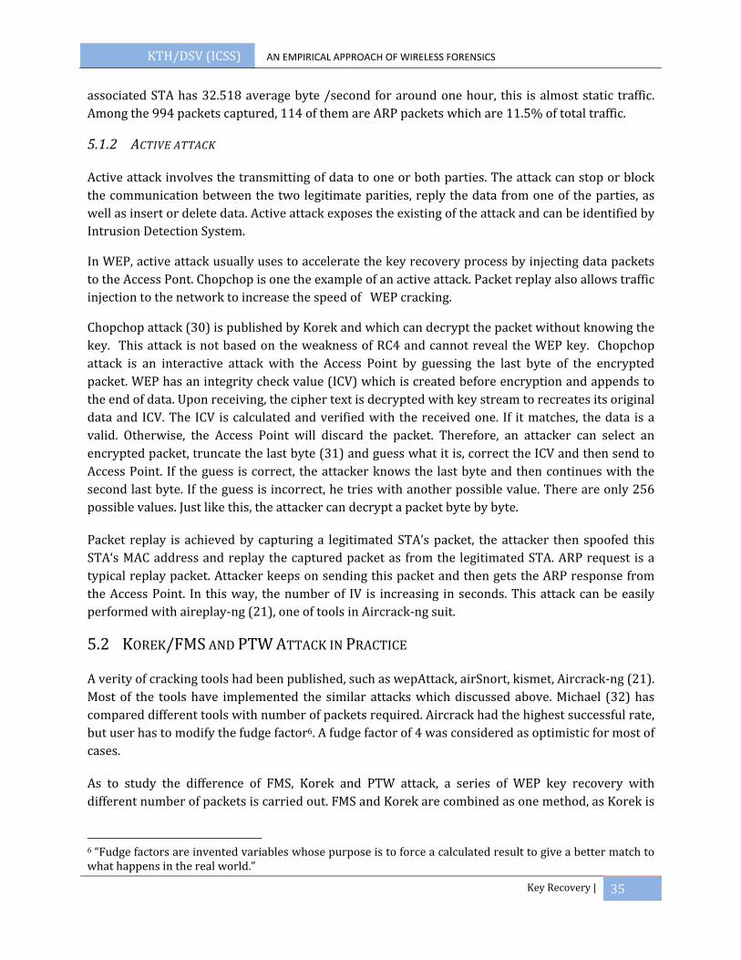
KTH/DSV (ICSS) AN EMPIRICAL APPROACH OF WIRELESS FORENSICS
Key Recovery | 35
associated STA has 32.518 average byte /second for around one hour, this is almost static traffic. Among the 994 packets captured, 114 of them are ARP packets which are 11.5% of total traffic.
5.1.2 ACTIVE ATTACK
Active attack involves the transmitting of data to one or both parties. The attack can stop or block the communication between the two legitimate parities, reply the data from one of the parties, as well as insert or delete data. Active attack exposes the existing of the attack and can be identified by Intrusion Detection System.
In WEP, active attack usually uses to accelerate the key recovery process by injecting data packets to the Access Pont. Chopchop is one the example of an active attack. Packet replay also allows traffic injection to the network to increase the speed of WEP cracking.
Chopchop attack (30) is published by Korek and which can decrypt the packet without knowing the key. This attack is not based on the weakness of RC4 and cannot reveal the WEP key. Chopchop attack is an interactive attack with the Access Point by guessing the last byte of the encrypted packet. WEP has an integrity check value (ICV) which is created before encryption and appends to the end of data. Upon receiving, the cipher text is decrypted with key stream to recreates its original data and ICV. The ICV is calculated and verified with the received one. If it matches, the data is a valid. Otherwise, the Access Point will discard the packet. Therefore, an attacker can select an encrypted packet, truncate the last byte (31) and guess what it is, correct the ICV and then send to Access Point. If the guess is correct, the attacker knows the last byte and then continues with the second last byte. If the guess is incorrect, he tries with another possible value. There are only 256 possible values. Just like this, the attacker can decrypt a packet byte by byte.
Packet replay is achieved by capturing a legitimated STA’s packet, the attacker then spoofed this STA‘s MAC address and replay the captured packet as from the legitimated STA. ARP request is a typical replay packet. Attacker keeps on sending this packet and then gets the ARP response from the Access Point. In this way, the number of IV is increasing in seconds. This attack can be easily performed with aireplay‐ng (21), one of tools in Aircrack‐ng suit.
5.2 KOREK/FMS AND PTW ATTACK IN PRACTICE
A verity of cracking tools had been published, such as wepAttack, airSnort, kismet, Aircrack‐ng (21). Most of the tools have implemented the similar attacks which discussed above. Michael (32) has compared different tools with number of packets required. Aircrack had the highest successful rate, but user has to modify the fudge factor6. A fudge factor of 4 was considered as optimistic for most of cases.
As to study the difference of FMS, Korek and PTW attack, a series of WEP key recovery with different number of packets is carried out. FMS and Korek are combined as one method, as Korek is
6 “Fudge factors are invented variables whose purpose is to force a calculated result to give a better match to what happens in the real world.”
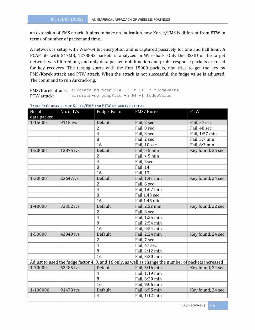
KTH/DSV (ICSS) AN EMPIRICAL APPROACH OF WIRELESS FORENSICS
Key Recovery | 36
an extension of FMS attack. It aims to have an indication how Korek/FMS is different from PTW in terms of number of packet and time.
A network is setup with WEP‐64 bit encryption and is captured passively for one and half hour. A PCAP file with 517MB, 1278882 packets is analyzed in Wireshark. Only the BSSID of the target network was filtered out, and only data packet, null function and probe response packets are used for key recovery. The testing starts with the first 15000 packets, and tries to get the key by FMS/Korek attack and PTW attack. When the attack is not successful, the fudge value is adjusted. The command to run Aircrack‐ng:
FMS/Korek attack: aircrack-ng pcapFile –K –n 64 –f fudgeValue
PTW attack: aircrack-ng pcapFile -n 64 –f fudgeValue
TABLE 6: COMPARISON OF KOREK/FMS AND PTW ATTACK IN PRACTICE
No. of data packet
No. of IVs Fudge Factor FMS/ Korek PTW
1‐15000 9115 ivs Default Fail, 2 sec Fail, 57 sec 2 Fail, 0 sec Fail, 48 sec 4 Fail, 3 sec Fail, 1:57 min 8 Fail, 2 sec Fail, 3:7 min 16 Fail, 10 sec Fail, 6:3 min1‐20000 13875 ivs Default Fail, > 5 min Key found, 25 sec 2 Fail, > 5 min 4 Fail, 5sec 8 Fail, 14 16 Fail, 13 1‐30000 23647ivs Default Fail, 1:41 min Key found, 24 sec 2 Fail, 6 sec 4 Fail, 1:07 min 8 Fail 1.43 sec 16 Fail 1.45 min 1‐40000 33352 ivs Default Fail, 2.52 min Key found, 22 sec 2 Fail, 6 sec 4 Fail, 1:35 min 8 Fail, 2:54 min 16 Fail, 2:54 min 1‐50000 43049 ivs Default Fail, 2:24 min Key found, 24 sec 2 Fail, 7 sec 4 Fail, 47 sec 8 Fail, 2:12 min 16 Fail, 3:30 min Adjust to used the fudge factor 4, 8, and 16 only, as well as change the number of packets increased 1‐70000 62485 ivs Default Fail, 5:16 min Key found, 24 sec 4 Fail, 1:19 min 8 Fail, 6:20 min 16 Fail, 9:06 min 1‐100000 91473 ivs Default Fail, 6:55 min Key found, 24 sec 4 Fail, 1:12 min
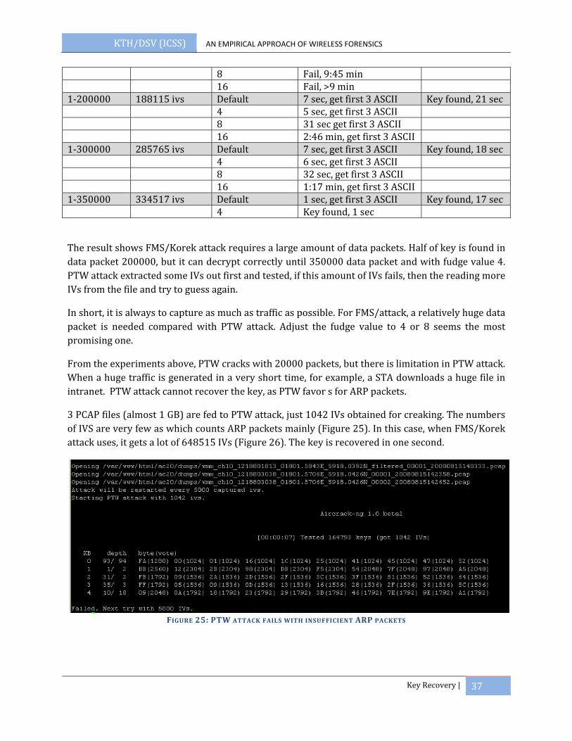
KTH/DSV (ICSS) AN EMPIRICAL APPROACH OF WIRELESS FORENSICS
Key Recovery | 37
8 Fail, 9:45 min 16 Fail, >9 min 1‐200000 188115 ivs Default 7 sec, get first 3 ASCII Key found, 21 sec 4 5 sec, get first 3 ASCII 8 31 sec get first 3 ASCII 16 2:46 min, get first 3 ASCII 1‐300000 285765 ivs Default 7 sec, get first 3 ASCII Key found, 18 sec 4 6 sec, get first 3 ASCII 8 32 sec, get first 3 ASCII 16 1:17 min, get first 3 ASCII 1‐350000 334517 ivs Default 1 sec, get first 3 ASCII Key found, 17 sec 4 Key found, 1 sec
The result shows FMS/Korek attack requires a large amount of data packets. Half of key is found in data packet 200000, but it can decrypt correctly until 350000 data packet and with fudge value 4. PTW attack extracted some IVs out first and tested, if this amount of IVs fails, then the reading more IVs from the file and try to guess again.
In short, it is always to capture as much as traffic as possible. For FMS/attack, a relatively huge data packet is needed compared with PTW attack. Adjust the fudge value to 4 or 8 seems the most promising one.
From the experiments above, PTW cracks with 20000 packets, but there is limitation in PTW attack. When a huge traffic is generated in a very short time, for example, a STA downloads a huge file in intranet. PTW attack cannot recover the key, as PTW favor s for ARP packets.
3 PCAP files (almost 1 GB) are fed to PTW attack, just 1042 IVs obtained for creaking. The numbers of IVS are very few as which counts ARP packets mainly (Figure 25). In this case, when FMS/Korek attack uses, it gets a lot of 648515 IVs (Figure 26). The key is recovered in one second.
FIGURE 25: PTW ATTACK FAILS WITH INSUFFICIENT ARP PACKETS

KTH/DSV (ICSS) AN EMPIRICAL APPROACH OF WIRELESS FORENSICS
Key Recovery | 38
FIGURE 26: FMS/KOREK ATTACK WITH LOTS OF DATA PACKET
5.3 ATTACKS TO VENDOR SPECIFIED ENCRYPTION ROUTER
After WEP has proved recoverable, different vendors have implemented their own solutions to solve the problem before WPA was released. The following testing focuses on how practical these solutions can be in real situation. An advanced router from Cisco is used. This router is usually for enterprise environment. The router is configured to all the available encryption for WEP. A STA is associated and the traffic between is captured. Aircrack‐ng is used to recover the key.
Access Point: Cisco Aironet 1200APAssociated STA: Intel® PRO/Wireless 2200BG
TABLE 7: WEP KEY RECOVERY TO CISCO AIRONET 1200AP
Test AP Configuration Recovery Result1 • WEP64 Recoverable2 • WEP 64 + MIC Recoverable with huge data packet, lot of IVs are
needed 3 • StandardWEP + MIC + Per Packet keying
(PPK)
Around 1G data (800000 IVs) cannot crack, a lot of negative votes from Aircrack‐ng running result.
4 • Key rotation enabled • Run for 2 hours to collect data and the
key are setting to rotate every 5 min
Get the key with around 500MB and 400 000 ivs.
5 • Cisco cipher wep64 Recoverable similar as with Test1
Table 7 shows the result of key recovery to Cisco Aironet 1200AP. WEP key can be recovered if MIC and PPK are not enabled. It is surprised the key rotation is not helpful to protect the network. The result shows enabling MIC and PPK in Cisco router can secure the network.
5.4 ATTACK WPA
WPA solves the security flaws in WEP. The techniques used to recover WEP are no longer effective in WPA protocol. WPA/802.11i is allowed in either enterprise or home mode. Enterprise mode means a RADIUS server is implemented for authentication. In the enterprise mode, the master key is generated dynamically for each connection. Although the key is recovered miraculous, this key is bound to a specific user in a specific session. Home mode is the Access Point and all STAs share a

KTH/DSV (ICSS) AN EMPIRICAL APPROACH OF WIRELESS FORENSICS
Key Recovery | 39
master key, called PSK. WPA‐PSK is very vulnerable during the exchange of four‐way handshake. When a valid four‐way handshake is captured, an attack can launch dictionary attack to guess the master key. If he is skillful enough to recover the key, the whole session can be decrypted in application layer and the network is accessible.
5.4.1 DICTIONARY ATTACK
Even three researchers from Norway published a cryptographically attack to TKIP, the temporal key can be recover in 2105 operations instead of 2128 operations in brute‐force (8). This attack is far impractical nowadays. The attack described in (20) , it proves an exploit in TKIP. The simplest attack to WPA‐PSK is dictionary attack. Dictionary attack is a technique to recover the key from likely possibilities which reduce the search space in brute force attack. It is based on the assumption of human beings tend to choose a short, simple and easy single word from the dictionary. A dictionary attack will try all the words in a text file, hash word by word and expect to get the PMK.
5.4.2 RAINBOW TABLE
The PMK generated from the PSK has added SSID as a salt. Even though two Access Points use the same PSK coincidently, the PMK will be different when the SSIDs are different. The salt and hashed 4096 times in PMK process results time consuming and complication in cracking.
As to save time in cracking, attacker can pre‐compute a big dictionary file with common passwords and SSID, and hash them all once, which is called rainbow table. “A rainbow table is a lookup table offering a time‐memory tradeoff used in recovering the plaintext password from a password hash generated by a hash function, often a cryptographic hash function.” (33). The project “Church of Wifi Uber coWPAtty lookup tables” (34) has computed all possible keys with all possible SSIDs. The SSIDs are from the top 1000 SSID in wiggle.net (35). The statistic was amazing. Among 5million of Access Point, 10% were using <no ssid>, about 15% are using the default SSID comes with the Access Point, such as linksys, default or NETGEAR. The project pre‐compute the SSID with 7GB well‐knows passwords and generated a 33GB rainbow table for downloading from the internet (34).
5.4.3 DICTIONARY FILE EXPANSION
A good dictionary file is critical in WPA‐PSK cracking. The PSK chosen can be different from country to country and language to language. It is important to feed the cracking tools with a proper dictionary file. For example, Swedish alphabets have 3 characters more than in English. Besides, people d not simple use words directly from dictionary, but something like “pa55w0rd” instead of “password”. To extend the possible keys in a file, a UNIX password cracking tools John the Ripper’s (36) wordlist mangling rules can be used to create permutations based on a simple file.
5.4.4 HARDWARE ACCELERATION

KTH/DSV (ICSS) AN EMPIRICAL APPROACH OF WIRELESS FORENSICS
Key Recovery | 40
Field programmable gate array (FPGA) is a semiconductor device that can be programmed by logic circuit diagram or source code in hardware level to specify how the chip should work. FPGA card can manufactured by Pico Computing (37) helps to accelerate the cracking speed in hardware level. A single FPGA card takes words 5 times faster than a 3.6GHz P4 laptop. This can also offload the using of CPU. However, FPGA card is not widely using for WPA cracking. It is a proprietary product from Pico Computing that costs very high and is unaffordable for a normal attacker. FPGA is running with coWPAtty initially, but Aircrack‐ng gains much more population than coWPAtty. Aircrack‐ng takes around 450 words per second while coWPAtty takes around 600 words per second with FPGA acceleration. As the difference is not so significant, it could be one of the reasons FPGA acceleration is not widely used in WPA cracking.
The other acceleration hardware is graphics processing unit (GPU) based password recovery. GPU accelerates the cracking speed 100 times than CPU, if a core2 Duo takes 400 passwords per second, which makes brute force WPA possible in time horizon. Currently Elcomsoft (38) has published its password recovery tools on GPU board and pyrite (39) is a Linux based open source software.
5.5 TIME ESTIMATION OF WPA ATTACK BY DICTIONARY
As to study how feasible WPA‐PSK can be recovery by dictionary attack, a dictionary generated with words and numbers are estimated with the cracking tools mentioned above.
Brute force attack is the ideal way of cracking WPA, but it is not feasible in reality. The possible ASCII character set has 95 symbols (52 letters, 10 number and33 symbols), so an 8 character password will be 958 possible combinations. Since human being favors easy to remember password, dictionary attack is more realistic. A sample of login information from MySpace member shows the average password length is 8 characters and 81% of those consist of both letter and numbers (40). Around 3.8% of password is a single word from dictionary and 12% is a word with a final digital.
From the fact above, the possible number of dictionary is generated. The dictionary generated give passphrase like, grass, grass1, grass12, grass23, grass32, grassgrass123, gra123ss, 1gr23ass, and any combination of word with digitals.
The number of possible passwords:
10 c
Where N=number of English words, n=number of digits in a password, C=average length of words.
According to the dictionary from Oxford (41), there are 171,476 words in current use, 47,156 obsolete words and around 9,500 derivative words in the Second Edition of Oxford English Dictionary. Assume the total number of English word is 228132, average length of a word is 5 and the number of digital using is 3, the number of possible passwords is

KTH/DSV (ICSS) AN EMPIRICAL APPROACH OF WIRELESS FORENSICS
Key Recovery | 41
3 228132 228132 10 5
By calculating the equation, the total number of words is 76652352000 words. Table 8 shows the time difference with different hardware configuration. GPU and Rainbow Table give the most promising result.
TABLE 8: ESTIMATION OF TIME BASED ON THE ENGLISH WORDS
Hardware configuration Software used Average speed Estimated timehour day
Core2duo, 2GHZ CPU Aircrack‐ng 450 word/second 47916.31 1996.51FPGA (Pico E‐12) CoWPAtty 600 word/second 35937.23 1497.38CPU running Rainbow Table (34) CoWPAtty 18000 hash/second 1197.91 49.91GPU (2x GeForce295 GTX (CUDA)) (39)
Pyrit 38000 hash/second 552.88 23.04
In the password generated, only 3 digits of numbers are considered. The increasing of number of words is dramatically when three digit of number are used (Figure 27). The drawback of this equation includes:
• Not all counted English words have 5 characters as the average of words, such as nail or pen. This equation doesn’t exclude the English words less than 5 characters
• The dictionary doesn’t consider the passphrase like “bluepen12”, which is a combination of 2 words less than 5 characters.
• The dictionary doesn’t count the some popular special characters like “_” or “‐”, which are also frequently used in passphrase
FIGURE 27: INCREASE OF WORDS WITH NUMBER OF DIGIT
5.6 DENIAL OF SERVICE ATTACK
228132 13687920 958154400
76652352000
number 0 number 1 number 2 number 3
Increase of words with number of digits
KTH/DSV (ICSS) AN EMPIRICAL APPROACH OF WIRELESS FORENSICS
Key Recovery | 42
DoS attack avoid the user accessing the network. From the view of malicious attention, it prohibits a legitimated STA to access the network resources. From the view of wireless forensics, it can prevent changes after seizure wireless communication and ensure the validity of evidence collected. Benjamin discuss how denial of service be helped in wireless forensics (24). The network machines have to be disconnected as soon as possible to prevent from remote access to alter the data in the computers being acquired for forensic analysis. DoS attack can be performed in different ways, such as injection of management packet and control frame or using the same frequency band to jam the network with white noise. Jamming creates an environment with natural disruption, which is not detectable but all networks in the area are affected. In this section, a handy and active way of DoS attack is discussed. The injection focuses on the target networks only, that eliminates the effects to other close by networks.
5.6.1 RTS/CTS INJECTION
In the CSMA/CA MAC, the link layer communication triggers by a RTS packet requesting to reserve the resources. The Access Point will respond with a CTS packet and broadcast to STAs. All STAs will back off and reserve the medium for RTS/CTS packet. Therefore a small RTS packet is used to reserve a large non‐contentious time. An intruder can simply sending RTS to Access Point and deny all the legitimated STAs to use the network resource. Rohit and Adrian (42) showed the catastrophic effect of jamming by RTS/CTS packet. The jamming can be performed in two ways, either sending CTS directly or sending RTS to Access Point and Access Point creates CTS. Sending CTS directly has a greater impact on bandwidth as it is not rate‐limited, but sending CTS through Access Point ensure in stealth mode.
5.6.2 DISASSOCIATION ATTACK
DoS attack can also be performed by sending a spoofed management packet. A Deauthentication frame can be sent to a legitimated STA or all associated STA. When a STA sends data or association response frame to the Access point, the attacker sends a spoofed Deauthentication frame with forged source address as the MAC address of Access Point. The Deauthentication packet is send directly to STA which will not be noticed by the Access Point. Aireplay‐ng can perform Deauthentication attack by simply issuing the command
aireplay-ng -0 1 -a AP_MAC_address -c victim_MAC_address ath0
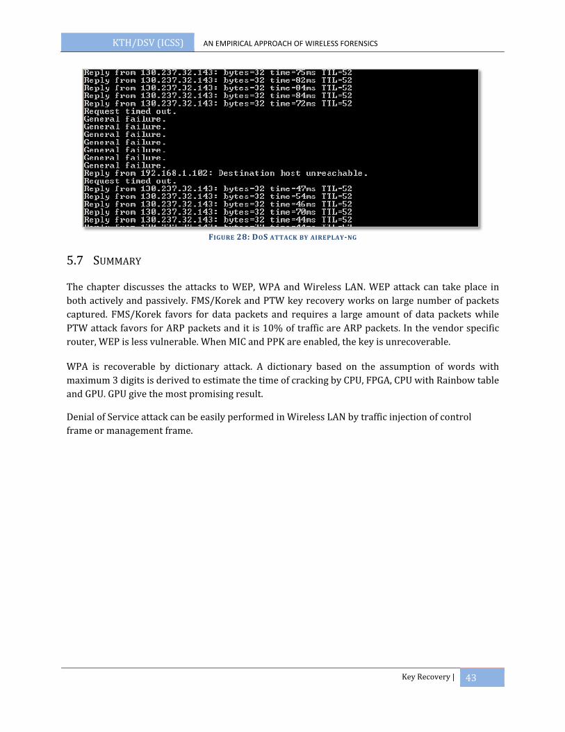
KTH/DSV (ICSS) AN EMPIRICAL APPROACH OF WIRELESS FORENSICS
Key Recovery | 43
FIGURE 28: DOS ATTACK BY AIREPLAYNG
5.7 SUMMARY
The chapter discusses the attacks to WEP, WPA and Wireless LAN. WEP attack can take place in both actively and passively. FMS/Korek and PTW key recovery works on large number of packets captured. FMS/Korek favors for data packets and requires a large amount of data packets while PTW attack favors for ARP packets and it is 10% of traffic are ARP packets. In the vendor specific router, WEP is less vulnerable. When MIC and PPK are enabled, the key is unrecoverable.
WPA is recoverable by dictionary attack. A dictionary based on the assumption of words with maximum 3 digits is derived to estimate the time of cracking by CPU, FPGA, CPU with Rainbow table and GPU. GPU give the most promising result.
Denial of Service attack can be easily performed in Wireless LAN by traffic injection of control frame or management frame.

KTH/DSV (ICSS) AN EMPIRICAL APPROACH OF WIRELESS FORENSICS
Data Analysis | 44
6 DATA ANALYSIS
After collected the traffic and recovered the key by the attacks covered in chapter 5, the data frame can be decrypted and view from application layer. There are a variety of commercial network forensic tools in the market, such as E‐Detective and NIKSUN’s NetDetector. Wireshark is one of the famous open source network analysis tools.
The traffic analysis should cover processes of data normalization and mining, traffic pattern recognition, protocol dissection and session reconstruction (43). In this chapter, two simple TCP and UDP session reconstruction will be demonstrated. Besides, some issues especially for wireless traffic analysis are also discussed.
6.1 RECONSTRUCTION IN APPLICATION LAYER
Application layer reconstruction is crucial steps in a forensic process where the examiner can find live evidence. Data reconstruction can be separated in 2 main streams which depend on their transport layers: Transmission Control Protocol (TCP) Session Reconstruction and User Datagram Protocol (UDP) Session Reconstruction.
TCP session reconstruction mainly uses for reconstruction of HTTP, Email and instant message. During the decryption process, each TCP Session is identified by 3‐way handshakes (44). By taken away the overhead of 802.11, the raw data for each session is collected. Based on the TCP well‐known port either in source or destination address, these raw data can be categorized in their corresponding application layer. For example, by filtering data on port 80, the forensic application can collect all information related to web activity through that port.
Figure 29 depicts a captured TCP packet which contains raw data HTTP Get Request. To have exactly look‐and‐feel as user experience, the forensic application needs to collect the raw data and present this data (HTML) in user‐friendly interface. Some commercial software like Unsniff Network Analyzer (45) or Iris (46) supports this feature.

KTH/DSV (ICSS) AN EMPIRICAL APPROACH OF WIRELESS FORENSICS
Data Analysis | 45
FIGURE 29: TCP PACKET DEPICTS IN WIRESHARK
UDP session reconstruction is for real‐time applications like VoIP. Reconstruct of VoIP is more difficult due to separate path between signaling and media traffic. To reconstruct a full VoIP session, it is required to capture both signaling, e.g. H.323 and SIP, and decode media codecs, e.g. G.711 PCMA and G723.1. Some VoIP applications like Skype, Office Communicator even use encrypted or non‐standard media codec, which makes the task of decoding VoIP more difficult. In general, VoIP session, particular media session is most interested for the forensic authority, because it provides conversation between the suspects. To decode media session, the decoding application needs to capture all traffic in Real‐time Protocol format (RTP) (47). The RTP packet is encapsulated by UDP packet, which has timestamp, packet sequence number and packetized voice. To reconstruct packetized voice, the decoding application first remove all header, it takes timestamp and sequence number and use jitter buffer to re‐order the digital voice in same sample rate as when the packets are packetized.
Figure 30 shows VoIP session decoded by Wireshark application. All packets are digitalized in G.711 PCMA, timestamp are increased 160 ms corresponding to their sample rate 8000 Hz and packet frame 20ms, the sequence number increase from 1 to 2, 3 and so on. The signaling session is Session Initiation Protocol (SIP) and the voice communication is recorded and can playback using RTP Player.
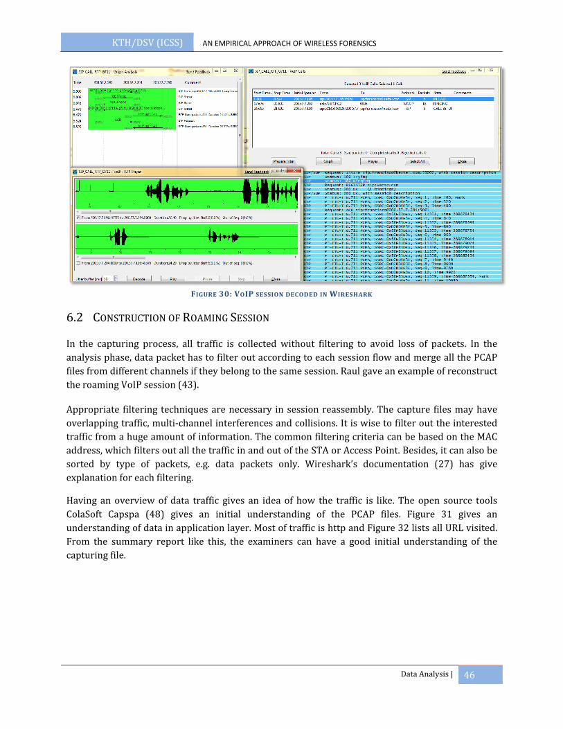
KTH/DSV (ICSS) AN EMPIRICAL APPROACH OF WIRELESS FORENSICS
Data Analysis | 46
FIGURE 30: VOIP SESSION DECODED IN WIRESHARK
6.2 CONSTRUCTION OF ROAMING SESSION
In the capturing process, all traffic is collected without filtering to avoid loss of packets. In the analysis phase, data packet has to filter out according to each session flow and merge all the PCAP files from different channels if they belong to the same session. Raul gave an example of reconstruct the roaming VoIP session (43).
Appropriate filtering techniques are necessary in session reassembly. The capture files may have overlapping traffic, multi‐channel interferences and collisions. It is wise to filter out the interested traffic from a huge amount of information. The common filtering criteria can be based on the MAC address, which filters out all the traffic in and out of the STA or Access Point. Besides, it can also be sorted by type of packets, e.g. data packets only. Wireshark’s documentation (27) has give explanation for each filtering.
Having an overview of data traffic gives an idea of how the traffic is like. The open source tools ColaSoft Capspa (48) gives an initial understanding of the PCAP files. Figure 31 gives an understanding of data in application layer. Most of traffic is http and Figure 32 lists all URL visited. From the summary report like this, the examiners can have a good initial understanding of the capturing file.

KTH/DSV (ICSS) AN EMPIRICAL APPROACH OF WIRELESS FORENSICS
Data Analysis | 47
FIGURE 31: AN OVERVIEW OF TRAFFIC FROM HIGHER LAYER PROTOCOL IN COLASOFT
FIGURE 32: COLASOFT SHOWS ALL HTTP REQUEST IN THE PCAP FILE
6.3 OTHER WIRELESS TRAFFIC ANALYSIS TECHNIQUES
An understanding of live data packet transmitting can gives the forensic analyst an advantage to identify the intruder /attacker immediately. After the key of that network is recovered, it is possible to decrypt all the data packets (WEP) or packets of this session (for WPA‐PSK) in live time. If the data traffic decrypted at the same time during the capturing, the examiner can monitor the traffic as in wired network and spot out the criminal at the scene.
Nowadays, most of the websites are enriched with graphics, such as company logo and application icons. An instant image viewer gives an immediate knowledge about what the suspect is doing. Figure 33 shows the picture dumped when the traffic is capturing in NetworkMiner (49). It shows the user is visiting Google and MSN Website. With an image viewer, the pictures tell what the capturing data is about.
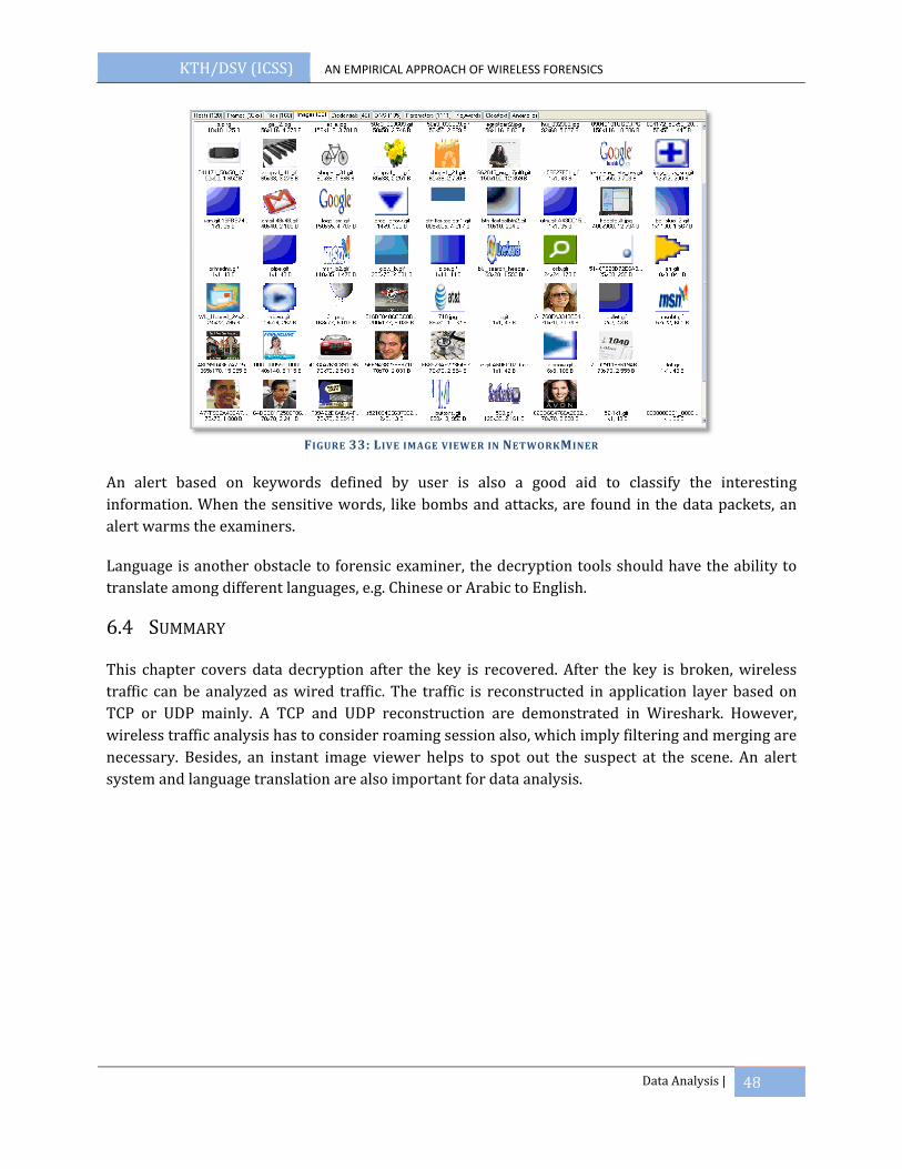
KTH/DSV (ICSS) AN EMPIRICAL APPROACH OF WIRELESS FORENSICS
Data Analysis | 48
FIGURE 33: LIVE IMAGE VIEWER IN NETWORKMINER
An alert based on keywords defined by user is also a good aid to classify the interesting information. When the sensitive words, like bombs and attacks, are found in the data packets, an alert warms the examiners.
Language is another obstacle to forensic examiner, the decryption tools should have the ability to translate among different languages, e.g. Chinese or Arabic to English.
6.4 SUMMARY
This chapter covers data decryption after the key is recovered. After the key is broken, wireless traffic can be analyzed as wired traffic. The traffic is reconstructed in application layer based on TCP or UDP mainly. A TCP and UDP reconstruction are demonstrated in Wireshark. However, wireless traffic analysis has to consider roaming session also, which imply filtering and merging are necessary. Besides, an instant image viewer helps to spot out the suspect at the scene. An alert system and language translation are also important for data analysis.
KTH/DSV (ICSS) AN EMPIRICAL APPROACH OF WIRELESS FORENSICS
Wireless Device Location | 49
7 WIRELESS DEVICE LOCATION
The last phase is to spot out the suspect in the scene. After identifying the existence of wireless access point and wireless device, it is important for a forensic examiner to point out the location of the targeted wireless device, such as a rouge AP or an intruder. It is much more complicated to locate a wireless device compared with in wired network. In wired network, it can be traced by ISP and lead to the attacker. In wireless network, attackers are connecting to other’s Access Point from far away. Tracing by ISP leads to the attacked network, but not the attacker. The following sections discuses the existing wireless positioning methods and its challenges. A new method is proposed for live spotting in the field.
7.1 EXISTING POSITIONING TECHNIQUES
The nature of radio frequency is a major challenge. The signal received cannot represent the original signal due to reflection, refraction, diffraction or scattering both in time and space. The accuracy of location is another issue: fine‐grained or coarse‐grained. This section discusses the technologies used nowadays and their accuracy. The existing location and tracking methods include closest access point, global positioning system, triangulation method, and radio frequency fingerprinting.
Closest Access Point is based on the theory that a STA is only associated with the closet Access Point. Therefore, the STA must be inside the cell area of the Access Point. It is easier to determinate the location of Access Point in WLAN. After the Access Point is found, the STA is located within the radius of the Access Point cell. This way of locating devices is fast and simple, but the accuracy is low. If the Access Points are placed 20 meters apart from each other, the total coverage area is narrowed down to around 400m2. That is too inaccurate to pinpoint a device. Besides, if a directional antenna is using, the intruder can be sitting far away from the Access Point.
GPS positioning is the most effective when it is in outdoor environment. It is a global satellite based system by making use of the 24 satellites orbiting above the earth in geosynchronous orbit that transmit their position and time of day to any device on the Earth’s surface that happens to be listening (50). No matter in which point of the earth, there are always 4 satellites above the horizon. Through triangulation of three or four signals received, it is able to accurately determine a user’s location to within a meter. The problem of GPS is the receiver must have a clear sight with the satellite. However, 802.11 networks are deployed both indoor and outdoor. In an indoor environment, the GPS transmission is blocked by buildings.
Triangulation locates the wireless device by taking the received signal strength indication (RSSI) from multiple Access Points. If a query for locating a device is received, all Access Points report the RSSI if they can read the signal strength of the device. The RSSI values are used to triangulate and determine location by intersection. As the locations of Access Points are known, the system will draw a circle by taking the RSSI as a radius. The stronger the RSSI value, the closet the device is the

KTH/DSV (ICSS) AN EMPIRICAL APPROACH OF WIRELESS FORENSICS
Wireless Device Location | 50
to Access point. The intersection of the 3 circles is the location of the wireless device (Figure 34). In triangulation, signal strength is treating uniformly from all the direction and the stronger signal has shorter distance in assumption. But in reality, the signal strength is affecting by the thickness of wall, interference, and objects between the transmitter and receiver (51). In order to have triangulation among Access Point, certain system has to be deployed to take the readings from Access Points placed in fixed position.
FIGURE 34: TRIANGULATION USING THREE ACCESS POINTS
Fingerprinting is similar as triangulation, but much more comprehensive. As in triangulation, numerous Access Points are placed in different position in the area for RSSI reporting. The RSSI measured in a specific position is calibrated with the training data in the database. The database is a set of RF fingerprints. An administrator has to walk around and take the fingerprints of real‐world data regarding the objects around. When receiving any query of location a device, RSSI value read from the Access Point is compared with the database if there is a match. Bahl and Padmanabhan (52) prove the empirical signal strength offering the most accurate result. However, the collection of fingerprints takes a lot of time and manual effort. If there is any change in the area, recalibration is necessary. Many studies have made to discuss how the Access Point should be placed. The grid architecture with densely‐spaced Access Point in a structure format is suggested to be the best solution by Aruba Wireless Network (53).
7.2 LOCATING DEVICES WITH RSSI AND TWO ANTENNAS
As the existing methods require infrastructures, it is not possible for a forensics examiner to find out the target in the field without these infrastructures. In this section, a method using RSSI with two antennas for location and tracking is proposed. The advantage of this method is dynamic and can be implemented to any laptop to work in the field.
There are two reasons for using RSSI with antennas.
Firstly, RSSI is available as long as there is data traffic, no matter inside the building or in outdoor area.

KTH/DSV (ICSS) AN EMPIRICAL APPROACH OF WIRELESS FORENSICS
Wireless Device Location | 51
Secondly, the location tool should adapt to a dynamic environment where intruders are sitting far away from the scene and no infrastructure is required before tracking the device, just like in RF fingerprinting which takes a lot of cost and setup, as well as administrative work. A system with simply RSSI value is much easier to deploy, but of course accuracy is a trade‐off.
A lot of studies have done to locate the wireless device based on signal strength, and most are using multiple gathered RSSI value to triangulate the target’s coordinate. IEEE 802.11 defines Receive Signal Strength Indicator (RSSI) as a standard to measure the RF energy on the circuitry of a wireless card. The value is allowed from 0‐255 (54) , but different vendor defines their own maximum RSSI (RSSI_Max) value, such as the Atheros chipset has an RSSI_Max value of 60. RSSI has critical usage in WLAN. When a STA wants to transmit a packet, it senses if the channel is clear by Clear Channel Threshold predefined. The decision for roaming also depends on the Roaming Threshold and some intermediate RSSI value
Based on the work of Bahl (52), they validated a STA gets stronger signal when it is closer to the Access Point, so it is possible to locate a STA connected to the Access Point inside a building with high degree of accuracy within 2 to 3 meter based on RSSI received. They illustrated the determination of location based on recording and processing real‐time RSSI collected from multiple STAs and positioned the target with triangulate technique. Empirical data was used to adjustment and a fine‐grained result was obtained.
From the work above, RSSI is a useful parameter for location tracking. The RSSI value collected is from the transmitting of packets. However, if a STA is in power‐savings mode or inactive mode, the RSSI values are not enough to identify the device. In that case, an active sending of RTS/CTS is proposed to ensure the continuous communication for RSSI retrieval.
Location based on signal strength requires processing continuous and real time signal strength information. Most of the Access Point sends out 10 beacons per seconds, which has enough information for location. However, STA will not send packets continuously. 802.11 has also defined power‐savings mode, when STA is in sleep mode when there is no communication. In order to collect enough signals, sending packet actively is proposed.
The positioning tool will send RTS/CTS continuously to get the signal strength from target device. RTS/CTS are the control packets which use to reserve the media. The received side is expected to respond with a CTS packet if it receives the RTS and the media is free. RTS/CTS packets are designed to be honored by all STAs in the range. If two Access Points are using the same channel, two networks are also honor to CTS when they hear it. This may seem interesting, but in WLAN, control packets are unauthenticated. By sending RTS and getting CTS constantly, even the STA is inactive mode, unassociated and unauthenticated, there is always RSSI available for tracking. RTS and CTS have been widely used in ad‐hoc network to avoid hidden nodes and exposed terminal problems.
Furthermore, radio signal is significant fluctuation. The 802.11 signal is multipath propagation, which means the signal will come from different paths and with different phases, different variation

KTH/DSV (ICSS) AN EMPIRICAL APPROACH OF WIRELESS FORENSICS
Wireless Device Location | 52
of the actual signal. Ansari described the fading effect of multipath. As to eliminate the effect of multipath, an average signal strength using averaging formula is taken.
RSSI1 RSSI2 RSSIn (50), n is the number of interval. When n is increasing, the error of RSSI is fading.
As to reduce the multipath effect, the retrieved RSSI from CTS is averaged with the number of RTS packets sending. For example, if 10 RTS packets are send per second, the
RSSIcts=RSSI1 RSSI2 RSSI10.
Besides, two antennas are equipped with a laptop externally. One of the antennas is directional antenna and the other one is omnidirectional antenna. Theoretically, when both antennas are using to receive the signal strength, the directional antenna should have higher gain than the omnidirectional antenna if the direction antenna is facing the target. It is preferable to have two antennas with the same gain for RSSI comparison. As shown in Figure 35, the direction antenna has full gain when it is facing the target device. The omnidirectional antenna has a uniform gain in the whole horizontal view.
FIGURE 35: RF ANTENNA PATTERN IN DIRECTION AND OMNIDIRECTIONAL
An omnidirectional antenna transmits or receives uniformly from any directions. This antenna is suitable for broadcasting signals to all devices in the range and listening from all the points. Access Point usually has an omnidirectional antenna. A directional antenna is favor for a particular direction. All RF energy is distributed in a specify area, so it has higher signal strength. Gain and directivity are the indicators of a directional antenna. dBi is one way to measure the gain. The directional antenna, EA‐ID6D, used in the experiments in section 7.3.3, has 6dBi gain and the patter is shown in Figure 35 .
When the signal strength from both antennas is compared in different positions, user can identify the direction of target much easier (Table 9). The omnidirectional antenna is acting as a reference
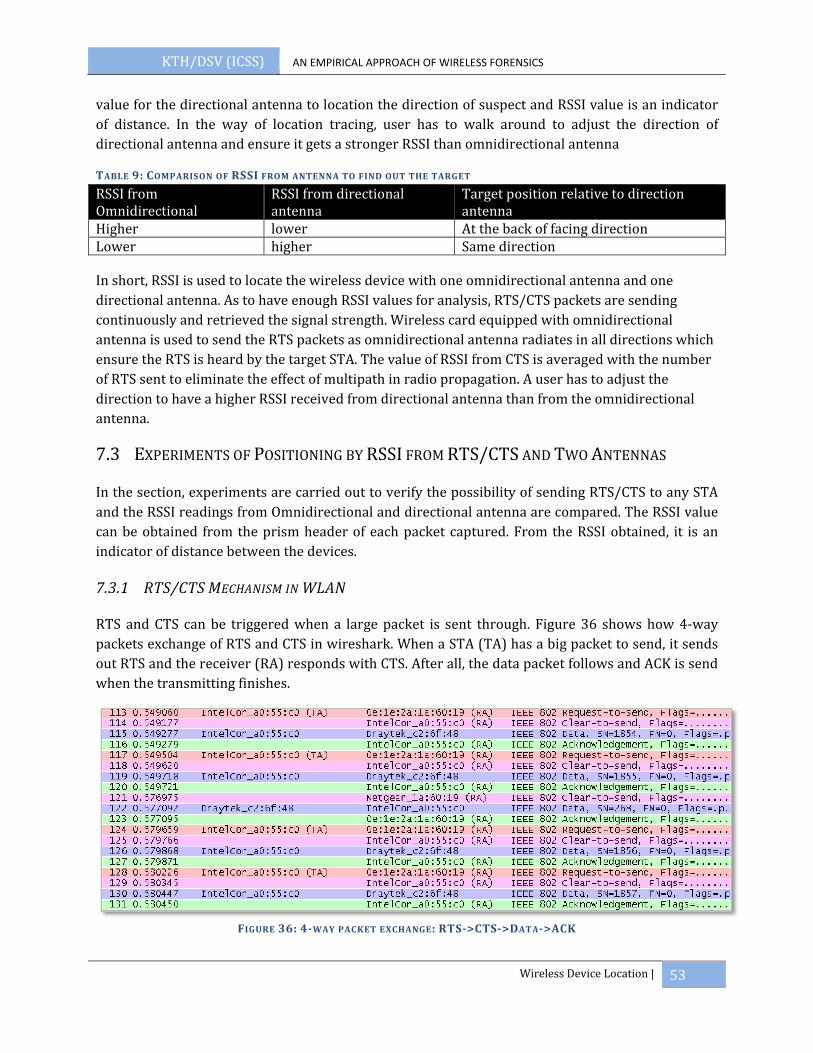
KTH/DSV (ICSS) AN EMPIRICAL APPROACH OF WIRELESS FORENSICS
Wireless Device Location | 53
value for the directional antenna to location the direction of suspect and RSSI value is an indicator of distance. In the way of location tracing, user has to walk around to adjust the direction of directional antenna and ensure it gets a stronger RSSI than omnidirectional antenna
TABLE 9: COMPARISON OF RSSI FROM ANTENNA TO FIND OUT THE TARGET
RSSI from Omnidirectional
RSSI from directional antenna
Target position relative to direction antenna
Higher lower At the back of facing direction Lower higher Same direction
In short, RSSI is used to locate the wireless device with one omnidirectional antenna and one directional antenna. As to have enough RSSI values for analysis, RTS/CTS packets are sending continuously and retrieved the signal strength. Wireless card equipped with omnidirectional antenna is used to send the RTS packets as omnidirectional antenna radiates in all directions which ensure the RTS is heard by the target STA. The value of RSSI from CTS is averaged with the number of RTS sent to eliminate the effect of multipath in radio propagation. A user has to adjust the direction to have a higher RSSI received from directional antenna than from the omnidirectional antenna.
7.3 EXPERIMENTS OF POSITIONING BY RSSI FROM RTS/CTS AND TWO ANTENNAS
In the section, experiments are carried out to verify the possibility of sending RTS/CTS to any STA and the RSSI readings from Omnidirectional and directional antenna are compared. The RSSI value can be obtained from the prism header of each packet captured. From the RSSI obtained, it is an indicator of distance between the devices.
7.3.1 RTS/CTS MECHANISM IN WLAN
RTS and CTS can be triggered when a large packet is sent through. Figure 36 shows how 4‐way packets exchange of RTS and CTS in wireshark. When a STA (TA) has a big packet to send, it sends out RTS and the receiver (RA) responds with CTS. After all, the data packet follows and ACK is send when the transmitting finishes.
FIGURE 36: 4WAY PACKET EXCHANGE: RTS>CTS>DATA>ACK
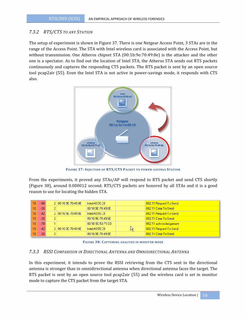
KTH/DSV (ICSS) AN EMPIRICAL APPROACH OF WIRELESS FORENSICS
Wireless Device Location | 54
7.3.2 RTS/CTS TO ANY STATION
The setup of experiment is shown in Figure 37. There is one Netgear Access Point, 3 STAs are in the range of the Access Point. The STA with Intel wireless card is associated with the Access Point, but without transmission. One Atheros chipset STA (00:1b:9e:70:49:8e) is the attacker and the other one is a spectator. As to find out the location of Intel STA, the Atheros STA sends out RTS packets continuously and captures the responding CTS packets. The RTS packet is sent by an open source tool pcap2air (55). Even the Intel STA is not active in power‐savings mode, it responds with CTS also.
FIGURE 37: INJECTION OF RTS/CTS PACKET TO POWERSAVINGS STATION
From the experiments, it proved any STAs/AP will respond to RTS packet and send CTS shortly (Figure 38), around 0.000012 second. RTS/CTS packets are honored by all STAs and it is a good reason to use for locating the hidden STA.
FIGURE 38: CAPTURING ANALYSIS IN MONITOR MODE
7.3.3 RSSI COMPARISON IN DIRECTIONAL ANTENNA AND OMNIDIRECTIONAL ANTENNA
In this experiment, it intends to prove the RSSI retrieving from the CTS sent in the directional antenna is stronger than in omnidirectional antenna when directional antenna faces the target. The RTS packet is sent by an open source tool pcap2air (55) and the wireless card is set in monitor mode to capture the CTS packet from the target STA.
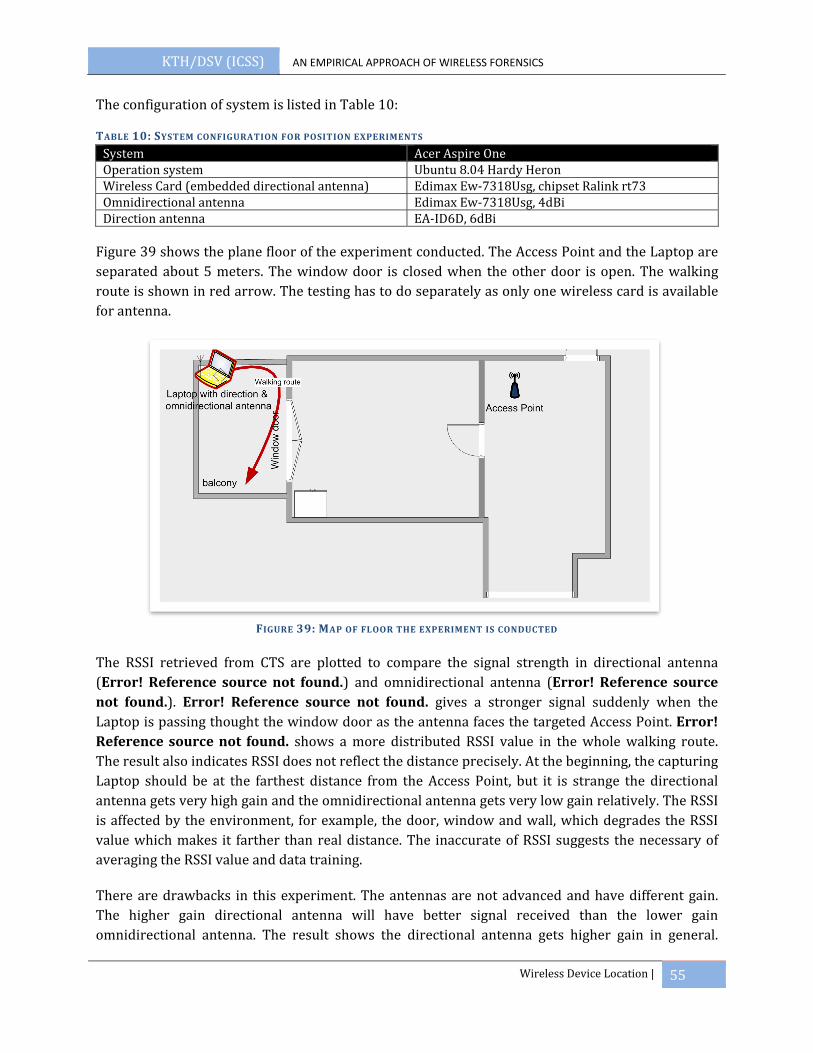
KTH/DSV (ICSS) AN EMPIRICAL APPROACH OF WIRELESS FORENSICS
Wireless Device Location | 55
The configuration of system is listed in Table 10:
TABLE 10: SYSTEM CONFIGURATION FOR POSITION EXPERIMENTS
System Acer Aspire OneOperation system Ubuntu 8.04 Hardy HeronWireless Card (embedded directional antenna) Edimax Ew‐7318Usg, chipset Ralink rt73 Omnidirectional antenna Edimax Ew‐7318Usg, 4dBiDirection antenna EA‐ID6D, 6dBi
Figure 39 shows the plane floor of the experiment conducted. The Access Point and the Laptop are separated about 5 meters. The window door is closed when the other door is open. The walking route is shown in red arrow. The testing has to do separately as only one wireless card is available for antenna.
FIGURE 39: MAP OF FLOOR THE EXPERIMENT IS CONDUCTED
The RSSI retrieved from CTS are plotted to compare the signal strength in directional antenna (Error! Reference source not found.) and omnidirectional antenna (Error! Reference source not found.). Error! Reference source not found. gives a stronger signal suddenly when the Laptop is passing thought the window door as the antenna faces the targeted Access Point. Error! Reference source not found. shows a more distributed RSSI value in the whole walking route. The result also indicates RSSI does not reflect the distance precisely. At the beginning, the capturing Laptop should be at the farthest distance from the Access Point, but it is strange the directional antenna gets very high gain and the omnidirectional antenna gets very low gain relatively. The RSSI is affected by the environment, for example, the door, window and wall, which degrades the RSSI value which makes it farther than real distance. The inaccurate of RSSI suggests the necessary of averaging the RSSI value and data training.
There are drawbacks in this experiment. The antennas are not advanced and have different gain. The higher gain directional antenna will have better signal received than the lower gain omnidirectional antenna. The result shows the directional antenna gets higher gain in general.

KTH/DSV (ICSS) AN EMPIRICAL APPROACH OF WIRELESS FORENSICS
| 56
Secondly, the experiment has to perform separately which results environmental difference and RSSI affected.
FIGURE 40:RSSI OF DIRECTIONAL ANTENNA FIGURE 41:RSSI OF OMNIDIRECTIONAL ANTENNA
7.4 SUMMARY
The chapter suggests using RSSI as well as directional and omnidirectional antenna for device location. The comparison of RSSI from directional and omnidirectional antenna finds the direction of the target. As to ensure the continuous of RSSI from the target device, RTS packet is sent actively to get CTS packet in return. The value of RSSI is average by the number of RTS sent to eliminate the effect of multipath in radio propagation. Experiments have proved all stations respond to RTS packets and RSSI received from directional and omnidirectional antenna can be an indicator for direction.
90
92
94
96
98
100
102
104
106
108
130 59 88 117
146
175
204
233
262
291
320
349
378
407
436
465
494
523
552
581
610
639
668
697
RSSI of Directional Antenna
93
94
95
96
97
98
99
100
101
102
103
1 22 43 64 8510
612
714
816
919
021
123
225
327
429
531
633
735
837
940
042
144
246
348
450
552
6
RSSI of Omni‐Directional AntennaRSSI RSSI
No. of Packets No. of Packets

KTH/DSV (ICSS) AN EMPIRICAL APPROACH OF WIRELESS FORENSICS
Conclusion | 57
8 CONCLUSION
In this thesis, wireless forensic has been suggested as a five‐phase process: network discovery, data capturing, key recovery, data analysis and wireless device positioning. Experiments are carried to evaluate the techniques discussed, give as a reference and proof‐of‐concept.
The first phase is network discovery. A war driving has illustrated to discover the networks in Stockholm city. Around 1500 Access Points are found and the data are analyzed to study the configuration of Access Point in terms of channel, encryption, and authentication.
The next phase is data capturing after understanding the environment. As to identify how far the capturing tool should be placed to have good enough signal for data capturing and safe enough for the examiners, a measurement of data loss at the signal level of good, fair and weak defined in thesis presents that only good received signal strength is suitable for data capturing. The signal received and distance can be adjusted by a suitable high gain antenna.
The third phase is key recovery. In the key recovery, FMS/Korek and PTW attack are compared in different numbers of packets. The results shows FMS/Korek requires large data packet while PTS attack requires relatively much less, but ARP packets. Another experiment to Cisco Aironet 1200AP shows WEP is secure with MIC and PPK enabled. WPA is vulnerable in four way handshake exchange which can be recovered by dictionary attack. A dictionary with all English words from Oxford dictionary with the maximum 3 digitals between is derived and estimated the time required for key recovery. The time of recovery is compared by CPU, FPGA, Rainbow Table and GPU based on the dictionary generated. GPU gives the shortest cracking time. As to secure the WLAN, a password with more than 8 random characters and digits is suggested to use.
The following phase is data analysis which can be separated in TCP and UDP mainly. Experiments show the reconstruction of TCP and VoIP in Wireshark. Wireless traffic reconstruction has to consider the roaming session also. Image viewer and language translation are also important tools for data analysis.
The last phase is to spot out the suspect in the field. RSSI with two antennas is proposed as a location method in the field. Experiments prove RTS/CTS packets can be used to ensure the data traffic and the two antennas can be used to find the direction.
8.1 FUTURE WORK:
In this thesis, all modules are described as a reference or guidelines. The modules can be developed into a practical tool to work in the field for wireless forensics purpose. The future work includes:
• Only 2.4GHz are considered in the thesis, but the future trend 802.11n supports both 5GHz and 2.4GHz. The network discovery and data capturing modules has to be capable of 802.11n as well.
KTH/DSV (ICSS) AN EMPIRICAL APPROACH OF WIRELESS FORENSICS
Conclusion | 58
• The accuracy of location module can be improved by applying propagation mode and normalization. A function of data set training in the scene can be helped to recognize the suspected device more accurately.
• Dictionary attack can be improved by having a comprehensive study on human being password, such as keyword patterns, English words and digits combination.
• A packet generator can be used to generate the packets and measure the loss of data packet in capturing in a more fine‐grained manner
• A real implementation includes all phases mentioned and automates the process for wireless forensics in a friendly GUI.
• An automatic flow is suggested in the implementation. A wizard is used to start with network discovery by specifying what to capture, in the meanwhile of capturing, the key recovery engine can be run in the background and tries to get the data decrypted. After decryption, forensic investigation can read all packets as in Ethernet and spot out the suspect.

KTH/DSV (ICSS) AN EMPIRICAL APPROACH OF WIRELESS FORENSICS
Bibliography | 59
9 BIBLIOGRAPHY
1. A roadmap for digital forensic research. [Online] 2001. http://dfrws.org/2001/dfrws‐rm‐final.pdf.
2. Marshalls Use of WEP Leads to 200m Stolen Credit Card Numbers. WiFi Net News. [Online] May 5, 2007. [Cited: March 10, 2009.] http://wifinetnews.com/archives/2007/05/marshalls_use_of_wep_leads_to_200m_stolen_credit_card_number.html.
3. Latest terror email sent from WiFi at Khalsa College. Expressindia. [Online] August 25, 2008. [Cited: March 10, 2009.] http://www.expressindia.com/latest‐news/Latest‐terror‐email‐sent‐from‐WiFi‐at‐Khalsa‐College/352813/.
4. Group, IEEE 802.11 Working. Wireless LAN Medium Access Control (MAC) and Physical Layer (PHY) Specifications. 1997. ISBN 1‐55937‐935‐9.
5. Johnny Cache, Vincent Liu. Radio Frequency. Hacking Exposed Wireless: Wireless Security Secrets & Solutions . s.l. : McGraw‐Hill, 2007.
6. Architecture Taxonomy for Control and Provisioning of Wireless Access Points (CAPWAP). [Online] June 2005. http://www.ietf.org/rfc/rfc4118.txt.
7. Costas Busch, Malik MagdonIsmail, Fikret Sivrikaya, B¨ulent Yener. ContentionFree MAC protocols for Wireless Sensor Networks. Troy NY 12180 USA : Rensselaer Polytechnic Institute, 2004.
8. Johnny Cache, Vincent Liu. Introduction to 802.11. Hacking Exposed Wireless: Wireless Security secrets and Solution. s.l. : McGraw‐Hill.
9. Geier, Jim. Understanding 802.11 Frame Types. Wifi Planet. [Online] 08 15, 2002. [Cited: 03 01, 2009.] http://www.wi‐fiplanet.com/tutorials/article.php/1447501.
10. Nikita Borisov, Ian Goldberg and David Wagner. Seucirty of the WEP algorithm. (In)Secuiryt of WEP algorithm. [Online] [Cited: 12 06, 2007.] http://www.isaac.cs.berkeley.edu/isaac/wep‐faq.html.
11. David Ross, Andrew Clark, Mark Looi. s.l. : Securly Deploying IEEE 802.11 WLANs. School of Software Engineering and Data communications, Queensland University of Technology, Australia, 2007, AusCERT2007 R&D Stream, pp. 50‐70.
12. Jon Edney, William A.Arbaugh. Real 802.11 Security: WiFi Protocol Access and 802.11i. s.l. : Addision‐Wesley Professional, 2004. ISBN‐10.
13. Eaton, Dennis. CommsDesign ‐ Diving into the 802.11i Spec: A Tutorial. [Online] Nov 26, 2002. [Cited: Sept 10, 2008.] http://commsdesign.com/design_library/cd/hn/OEG20021126S0003.

KTH/DSV (ICSS) AN EMPIRICAL APPROACH OF WIRELESS FORENSICS
Bibliography | 60
14. Computer forensics. Wikipedia . [Online] http://en.wikipedia.org/wiki/Computer_forensics.
15. U.S. Department of Justice. April 2004.A forensic examination of digital evidence: A guide for law enforcement.
16. Moskowitz, Robert. WLAN Testing reports "Debunking the Myth of SSID Hiding". s.l. : ICSA Labs, a division of TruSecure Corporation, 2003.
17. Scott Fluhrer, Itsik Mantin, and Adi Shamir. s.l. : Weaknesses in the Key Scheduling Algorithm of RC4. Proc. 4th Annual Workshop on Selected Areas in Cryptography, 2001.
18. Halil Lbrahim Bulbul, Ihsan Batmaz, Mesut Ozel. Wireless Network Security: Comparison of WEP (Wired Equivalent Privacy) Mechanism, WPA (WiFi Protected Access) and RSN (Robust Security Network) Security Protocols. Adelaide : e‐Forensics 2008, 2008. ICST.
19. Dictionary attack. Wikipedia. [Online] [Cited: 02 03, 2009.] http://en.wikipedia.org/wiki/Dictionary_attack.
20. Martin beck, Erik Tews. Practical attacs against WEP and WPA. Germany : TU‐Dresdan, 2008.
21. Aircrack‐ng. Aircrackng. [Online] [Cited: March 30, 2009.] http://www.aircrack‐ng.org/.
22. Siles, Raul. Wireless Forensics: Tapping the Air ‐Part One. [Online] 01 02, 2007. [Cited: 09 23, 2008.] http://www.securityfocus.com/infocus/1884.
23. Velasco, E., Chen, W., Ji, P., Hsieh, R. Challenges of location tracking techniques in wireless forensics. Harbin, China : s.n., 2008, 4th international Conferences on Intelligent Information Hiding and Multimedia Signal Processing. IIHMSP.
24. Benjamin Turnbull, Jill Slay. s.l. : Wireless Forensic Analysis Tools for use in the Electronic Evidence Collection Process. IEEE , 2007. Proceedings of the 40th Hawaii International conference on System Sciences .
25. the madwifi project. [Online] the madwifi project. http://madwifi‐project.org/.
26. tshark ‐ The Wireshark Network Analyzer 1.1.2. [Online] Wireshark . http://www.wireshark.org/docs/man‐pages/tshark.html.
27. Wireshark. Wireshark User's Guide. [Online] [Cited: 01 23, 2009.] http://www.wireshark.org/docs/wsug_html_chunked/ChWorkBuildDisplayFilterSection.html.
28. Montcalm, Erik. s.l. : How to Avoid Ethical and Legal Issues In Wireless Network Discovery. SANS Institute InfoSec Reading Room, 2003.
29. Pyshkin, Erik Tews and RalfPhilipp Weinmann and Andrei. Breaking 104 bit WEP in less than 60 seconds . Germany : TU Darmstadt, FB Informatik, 2007.

KTH/DSV (ICSS) AN EMPIRICAL APPROACH OF WIRELESS FORENSICS
Bibliography | 61
30. Byte‐Sized Decryption of WEP with Chopchop, part 1. General Security and Privacy. [Online] Pearson Education, Inc. Informit, June 09, 2006. [Cited: march 10, 2009.] http://www.informit.com/guides/printerfriendly.aspx?g=security&seqNum=196.
31. Byte‐Sized Decryption of WEP with Chopchop, Part 2. General Security and privacy. [Online] Pearson Education, Inc. Informit, June 16, 2006. [Cited: March 14, 2009.] http://www.informit.com/guides/printerfriendly.aspx?g=security&seqNum=197.
32. Ossmann, Michael. WEP: Dead Again, Part 1. SecurityFocus. [Online] [Cited: 12 23, 2008.] http://www.securityfocus.com/infocus/1814.
33. Rainbow table. Wikipedia. [Online] [Cited: January 06, 2009.] http://en.wikipedia.org/wiki/Rainbow_table.
34. Church of Wifi Uber coWPAtty lookup tables. Church of Wifi. [Online] February 18, 2007. [Cited: March 15, 2009.] http://www.churchofwifi.org/default.asp?PageLink=Project_Display.asp?PID=90.
35. WiGLE ‐ Wireless Geographic Logging Engine . [Online] [Cited: February 23, 2009.] http://www.wigle.net/gps/gps//Stat.
36. John the Ripper password cracker. Openwall Project. [Online] [Cited: August 23, 2008.] http://www.openwall.com/john/.
37. Pico Computing . Pico Computing, Inc. [Online] http://www.picocomputing.com/.
38. Password recovery, forensics, system and security software from Elcomsoft : recover or reset lost or forgotten password, remove protection, unlock system. [Online] Elcomsoft . http://www.elcomsoft.com.
39. pyrit. Pyrit Advances in attacking WPAPSK. [Online] [Cited: March 29, 2009.] http://code.google.com/p/pyrit/.
40. Joris Evers. Report: Net users picking safer password. ZDNet News. [Online] http://news.zdnet.com/2100‐1009_22‐150640.html.
41. AskOxford: How many words are there in the English Language. AskOxford.com. [Online] Decemeber 30, 2008. [Cited: March 29, 2009.] http://www.askoxford.com/asktheexperts/faq/aboutenglish/numberwords?view=uk.
42. Perrig, Rohit Negi and Adrian. Jamming analysis of MAC protocols. s.l. : Carnegie Mellon univerity , 2003. PA 15213.
43. siles, Raul. Wireless Forensics: Tapping the Air ‐ Part Two. [Online] 01 08, 2007. [Cited: 09 30, 2008.] http://www.securityfocus.com/infocus/1885.
44. RFC 793 ‐ Transmission Control Protocol. fags.org. [Online] [Cited: March 25, 2009.] http://www.faqs.org/rfcs/rfc793.html.
KTH/DSV (ICSS) AN EMPIRICAL APPROACH OF WIRELESS FORENSICS
Bibliography | 62
45. Unsniff Network Analyzer. Unsniff Network Analyzer. [Online] [Cited: March 25, 2009.] http://www.unleashnetworks.com/unsniff/unsniff‐2.html.
46. Network Forensics, Packet Capture & Network Traffic Analyzer | Iris. eEye Digital Security. [Online] [Cited: March 25, 2009.] http://www.eeye.com/html/products/iris/index.html.
47. RTP: A Transport Protocol for Real‐Time Applications. Network Working Group . [Online] July 2003. [Cited: March 22, 2009.] http://www.ietf.org/rfc/rfc3550.txt.
48. Network Packet Sniffer and Network Analyzer ‐ Colasoft. Colasoft. [Online] Colasoft. [Cited: 3 30, 2009.] http://www.colasoft.com/.
49. NetworkMiner packet analyzer. sourceforge.net. [Online] [Cited: October 12, 2008.] http://networkminer.wiki.sourceforge.net/NetworkMiner.
50. M.A.Ansari, Sherjeel Farooqui, AnsarUIHaque Yasar. s.l. : Low Cost Solution for Location Determination of Mobile Nodes in a Wireless Local Area Network . IEEE Xplore , 2005.
51. Emmanuel Velasco, Weifeng Chen, Ping Ji, Raymond Hsieh. Challenges of Location Tracking Techniques in Wireless Forensics. Harbin, China : 4th Internation Conferences on Intelligent Information Hiding and Multimedia Signal Procsssing, 2008. IIHMSP 2008.
52. Bahl Paramvir, Venkata N.Padmanabhan. User Location and Tracking in an InBuilding Radio. Redmond, WA 98052 : Miscrosoft Research, 1999. Technial Report MST‐TR‐99‐12. MSR‐TR‐99‐12.
53. Thornycroft, Peter. Location & tracking on the Mobile Edge. s.l. : Aruba Wireless Networks, 2004.
54. Joe Bardwell, Vp of Professional Coverting Signal strength percentage to dBm Values . Services. s.l. : WildPackets, 2002.
55. pcap2air. 802.11MERCENARY.NET. [Online] http://www.802.11mercenary.net/pcap2air/.
56. Pawliw, Borys. What is Rijndeal? SearchSecurity.com. [Online] May 28, 2007. [Cited: 03 12, 2009.] http://searchsecurity.techtarget.com/sDefinition/0,,sid14_gci523541,00.html.

KTH/DSV (ICSS) AN EMPIRICAL APPROACH OF WIRELESS FORENSICS
Glossary | 63
10 GLOSSARY
16‐QAM Quadrature amplitude modulation (QAM) is a modulation scheme which conveys two digital
bit streams or two analog message signals by changing (modulating) the amplitudes of two carrier waves, using the amplitude‐shift keying (ASK) digital modulation scheme or amplitude modulation (AM) analog modulation scheme. The most common forms are 16‐QAM, 64‐QAM, 128‐QAM and 256‐QAM.
5‐phase The five phases in wireless forensics suggested in this thesis, including network discovery,
data capturing, key recovery, data analysis and device positioning.
802.11a Operates in the 5‐GHz frequency range (5.125 to 5.85 GHz) with a maximum transmission
rate of 54Mbit/sec. The 5‐GHz frequency band has more radio channels than the 2.4‐GHz frequency (used in 802.11b/g) and is less crowded. However, it has a smaller range than 802.11b/g. It is not generally used in domestic wireless networks, but is supported by high‐end wireless equipment for business use from vendors such as Cisco Systems.
802.11b Operates in the 2.4‐GHz band (2.4 to 2.4835 GHz) and provides transmission rates of up to
11Mbit/sec. Generally used standard for domestic and business wireless networks, but can suffer from interference from other devices in the frequency range, such as microwave ovens, cordless phones, and Bluetooth devices. Forward compatible with 802.11g standard and many dual‐standard devices are referred to as 802.11b/g.
802.11i The new IEEE standard for security in 802.11 WLANs. 802.11i supersedes the WEP scheme
originally introduced with 802.11b wireless LANs. Devices that fully support 802.11i can use WEP, Wi‐Fi Protected Access (WPA) or AES for data encryption.
802.11n An extension to 802.11 specification developed by the IEEE for wireless LAN (WLAN)
technology. 802.11n builds upon previous 802.11 standards by adding multiple‐input multiple‐output (MIMO). The additional transmitter and receiver antennas allow for increased data throughput through spatial multiplexing and increased range by exploiting the spatial diversity through coding schemes like Alamouti coding. The speed is 100 Mbit/s (even 250 Mbit/s in PHY level), and so up to 4‐5 times faster than 802.11g. 802.11n also offers a better operating distance than current networks.
802.11x 802.1x is a scheme for port‐based security, which requires a user or device to authenticate
with the wireless access point or a wired LAN switch/hub, before it can communicate with other devices in the network. 802.1x is used in conjunction with the Extensible Authentication Protocol (EAP).

KTH/DSV (ICSS) AN EMPIRICAL APPROACH OF WIRELESS FORENSICS
Glossary | 64
Access Point A network device that serves as a communications "hub" for wireless clients. The AP
typically provides communications to a wired network. An AP establishes one or more Basic Service Sets in its area of radio coverage. WLAN clients that know the name of the BSS (its SSID) can try to authenticate and associate with the AP.
Ad‐hoc A wireless LAN client mode that operates an independent, peer‐to‐peer configuration with
other Ad‐Hoc clients. The alternative to Ad‐Hoc mode is Infrastructure Mode, which requires an 802.11 access point.
Advanced Encryption Standard (AES) A recent encryption standard based on the Rijndael algorithm, AES has been approved by the
US National Institute of Standards and Technology (NIST) for the Federal Information Processing Standard (FIPS‐197). AES is a symmetric encryption algorithm that will be used by U.S. Government organizations and many other organizations in the future, to protect the transmission of sensitive information. AES is being incorporated into the IEEE 802.11i standard for 802.11 WLAN security.
Association The process of "connecting" to an access point, which provides a WLAN client access to the
wireless and wired networks of an access point. A WLAN client must also successfully authenticate via the access point before it can access the network(s).
ARP The Address Resolution Protocol is a layer 2 protocol used to map MAC addresses to IP
addresses. All hosts on a network are located by their IP address, but NICs do not have IP addresses, they have MAC addresses. ARP is the protocol used to associate the IP address to a MAC address.
Authentication The process of identifying a person or a device prior to allowing communication or
conferring access rights to network resources. Authentication should ensure that an individual is who they claim to be.
Beacon Beacon Frames are frames that have control information and are transmitted in each of the
14 channels and help a wireless station to identify nearby wireless access points (AP). They tell the stations in the Basic Service Set (BSS) about the existence of the network. They can also be transmitted by the AP for polling purposes.
BSSID The MAC address of an access point that has set up a Basic Service Set (BSS).
Carrier Sense Multiple Access/Collision Avoidance (CSMA/CA) CSMA/CA is a modification of pure Carrier Sense Multiple Access (CSMA). Collision
avoidance is used to improve the performance of CSMA by attempting to be less "greedy" on the channel. If the channel is sensed busy before transmission then the transmission is deferred for a "random" interval. This reduces the probability of collisions on the channel.

KTH/DSV (ICSS) AN EMPIRICAL APPROACH OF WIRELESS FORENSICS
Glossary | 65
CCMP Counter Mode with Cipher Block Chaining Message Authentication Code Protocol is a
mandatory part of the WPA2 protocol and an optional part of the WPA protocol. It is an IEEE 802.11i encryption protocol created to replace TKIP and WEP protocol. CCMP uses the Advanced Encryption Standard (AES) algorithm. Unlike in TKIP, key management and message integrity is handled by a single component built around AES using a 128‐bit key and a 128‐bit block.
Complementary cod keying (CCK) Complementary Code Keying is a modulation scheme used with wireless networks (WLANs)
that employ the IEEE 802.11b specification.
Control frames 802.11 control frames assist in the delivery of data frames between stations.
CRC‐32 A cyclic redundancy check (CRC) is a non‐secure form of message digest designed to detect
accidental changes to raw computer data, and used in many modern digital networks and storage devices. CRC types are often identified by "polynomial," which is the number used as the divisor (given in hexadecimal format). One of the most commonly encountered of the CRC types is that used by Ethernet, FDDI, PKZIP, WinZip and PNG. It uses the polynomial 0x04C11DB7, and is known as "CRC‐32."
Data analysis Phase 4 of the five phases.
Data capturing Phase 2 of the five phases. dBi dBi ‐Decibels relative to an Isotropic antenna ‐ is a measure of an antenna's gain.
dBm dBm ‐Decibels relative to one milli‐Watt ‐ is a measure of power output.
Denial of Service attack A denial‐of‐service attack is an attempt to make a computer resource unavailable to its
intended users.
Device positioning Phase 5 of the five phases.
Dictionary attack A dictionary attack is a technique for defeating a cipher or authentication mechanism by
trying to determine its decryption key or passphrase by searching likely possibilities.
Direction Sequence Spread Spectrum (DSSS) Direct Sequence Spread Spectrum. The data transmission scheme (sometimes referred to as
a "modulation" scheme) used in 802.11b WLANs. DSSS uses a radio transmitter operating at a fixed centre frequency, but using a relatively broad range of frequencies, to spread data transmissions over a fixed range of the frequency band. 802.11a and 802.11g (when not

KTH/DSV (ICSS) AN EMPIRICAL APPROACH OF WIRELESS FORENSICS
Glossary | 66
operating in 802.11b mode) use Orthogonal Frequency Division Multiplexing (OFDM).
Directional antenna A directional antenna is an antenna which radiates greater power in one or more directions
allowing for increased performance on transmit and receive and reduced interference from unwanted sources.
Evil twin attack Evil twin is an attack similar in nature to Web site spoofing and e‐mail phishing attacks. A
hacker sets its service identifier (SSID) to be the same as a legitimate access point (AP). The hacker disrupts or disables the legitimate AP by disconnecting it, directing a denial of service against it, or creating RF interference around it. Users lose their connections to the legitimate AP and re‐connect to the "evil twin," allowing the hacker to intercept all the traffic to that device.
Extensible Authentication Protocol (EAP) EAP is the generic terms for a family of authentication protocols that can be employed in
wireless LANs for identifying users and verifying the authenticity of the network(s) they connect to. Mutual authentication is just one of many essential requirements for secure wireless networking.
Frequency Hopping Spread Spectrum (FHSS) Frequency‐Hopping Spread‐Spectrum (FHSS) is a spread‐spectrum technique used by
Bluetooth devices and some 802.11 1Mbps / 2Mbps WLANs. With FHSS, data is transmitted on a radio carrier which hops pseudo‐randomly across several different frequencies at a pre‐determined rate and hopping sequence. 802.11b devices use DSSS rather than FHSS. 802.11a and 802.11g devices use OFDM.
Hidden Network A wireless device that is intended to operate in a cell or area of coverage, but which cannot
hear the wireless transmissions of some other nodes, and so intermittently causes interference with them. Hidden nodes degrade the performance of a wireless network, and so need to be identified and corrected by the wireless LAN administrator.
ICV Integrity Check Value is used in WEP as integrity check. It is an additional 4‐byte computed
on the original packet and appended to the end, which is encrypted with RC4 cipher stream.
IEEE (The Institute of Electrical and Electronics engineers) Institute of Electrical and Electronics Engineers. A US‐based membership organization that
includes engineers, scientists, and students in electronics and related fields. The IEEE developed the 802 series wired and wireless LAN standards.
Independent Basic Service Set (IBSS) A BSS set up by an 802.11 WLAN station operating in an Ad‐Hoc Mode wireless network.
Industrial, Scientific and Medical (ISM) A range of radio frequencies that are assigned for use by unlicensed users of Industrial,
Scientific and Medical equipment, but which is also used by many other wireless devices, including 802.11, 802.11b and 802.11g devices, by Bluetooth and by microwave ovens. The

KTH/DSV (ICSS) AN EMPIRICAL APPROACH OF WIRELESS FORENSICS
Glossary | 67
Internationally‐recognized ISM band sits within the 2.4GHz ‐ 2.5GHz frequency range. In the US, two further ISM bands exist, in the 902MHz ‐ 928MHz range and the 5.725GHz ‐ 5.875GHz range.
Infrastructure mode A wireless LAN client mode that requires an access point (AP). Infrastructure Mode is the
alternative to Ad‐Hoc Mode. Clients operating in Infrastructure Mode pass data through a central access point. The access point manages wireless network traffic in the cell or area of coverage that it sets up (the BSS), and typically allows clients to communicate to and from a wired network.
Initialization vector (IV) In cryptography, an initialization vector (IV) is a block of bits that is required to allow a
stream cipher or a block cipher to be executed in any of several streaming modes of operation to produce a unique stream independent from other streams produced by the same encryption key, without having to go through a (usually lengthy) re‐keying process.
Key recovery Phase 3 of the five phases.
MAC Protocol data unit (MPDU) MAC Protocol Data Unit is packet of data going between the MAC and the antenna. It is
converted to MSDU upon reception and delivered to OS.
Management frames 802.11 management frames enable stations to establish and maintain communications.
Man‐in‐the‐Middle Attack Man‐in‐the‐middle attack is a form of active eavesdropping in which the attacker makes
independent connections with the victims and relays messages between them, making them believe that they are talking directly to each other over a private connection when in fact the entire conversation is controlled by the attacker.
Multiple‐input multiple‐output (MIMO) In radio, multiple‐input and multiple‐output, or MIMO (pronounced my‐moh), is the use of
multiple antennas at both the transmitter and receiver to improve communication performance. It is one of several forms of smart antenna technology and deployed in 802.11n.
MAC Service data unit (MSDU) MAC Service Data Unit is the packet of data going between the host computer’s software and
the wireless LAN MAC. For transmissions, MSDU are sent by the OS to the MAC layer and coverted to MPDUs ready to be send over the radio.
Network discovery Phase 1 of the five phases.
Omnidirectional antenna An omnidirectional antenna is an antenna system which radiates power uniformly in one
plane with a directive pattern shape in a perpendicular plane.
KTH/DSV (ICSS) AN EMPIRICAL APPROACH OF WIRELESS FORENSICS
Glossary | 68
Organizationally Unique Identifier (OUI) An Organizationally Unique Identifier (OUI) is a 24‐bit number that is purchased from IEEE
Registration Authority. This identifier uniquely identifies a vendor, manufacturer, or other organization globally or worldwide and effectively reserves a block of each possible type of derivative identifier for the exclusive use of the assignee.
Orthogonal Frequency Division Multiplexing (OFDM) coupling OFDM employs multiple overlapping radio frequency carriers, each operating at a carefully
chosen frequency that is Orthogonal to the others, to produce a transmission scheme that supports higher bit rates due to parallel channel operation. OFDM is an alternative transmission scheme to DSSS and FHSS.
Pair wise master key (PMK) Pair wise master key (PMK) is a key established between the wireless station and the access
point in 802.11i.
Per‐packet key mixing The key‐mixing function creates a new key for every packet transmitted in TKIP. It was
introduced for the protection against RC4 weak key attacks.
Promiscuous mode Promiscuous mode is a configuration of a network card that makes the card pass all traffic it
receives to the central processing unit rather than just packets addressed to it. It is a feature normally used for packet sniffing.
PTK The pair wise key hierarchy in 802.11i. PTK (pair wise transient key) is a set of keys derived
from PMK through a pseudorandom function.
Radio frequency(RF) A generic term for radio‐based technologies, operating between the Low Frequency range
(30k Hz) and the Extra High Frequency range (300 GHz).
RC4 RC4 generates a pseudorandom stream of bits (a key stream) which, for encryption, is
combined with the plaintext using bit‐wise exclusive‐or; decryption is performed the same way (since exclusive‐or is a symmetric operation). RC4 is widely used in SSL and WEP.
Remote Access Dial‐In User Service (RADIUS) Remote Authentication Dial In User Service (RADIUS) is a networking protocol that provides
centralized Authentication, Authorization and Accounting (AAA) management for computers to connect and use a network service.
Request to Send (RTS) and Clear to Send (CTS) RTS/CTS (Request to Send / Clear to Send) is a handshake protocol that can be used in
802.11 wireless networks as a means to identify and temporarily resolve the hidden node problem. The RTS/CTS threshold must be set correctly by the wireless LAN administrator.
RFMON Radio Frequency Monitoring (RFMON) is a passive method of WLAN discovery. It is a
KTH/DSV (ICSS) AN EMPIRICAL APPROACH OF WIRELESS FORENSICS
Glossary | 69
sniffing mode which allows the card to report drivers from the 802.11 layer. A client with a wireless card that is configured in RFMON mode will be able to capture all RF signals on the channels to which it is configured to listen. RFMON is a receive‐only mode. While in RFMON mode, wireless clients are unable to transmit any frames; their cards are only able to receive, and therefore capture traffic.
Roaming The ability to move seamlessly from one RF cell or coverage area to another without losing
higher layer network connectivity. Roaming in 802.11 wireless networks is not straightforward. For seamless roaming in multi‐vendor networks, an Inter‐Access Point Protocol (IAPP) is required, and there is no standard available at present. Where layer 2 encryption gateways or layer 3 VPNs are used, data can be lost during handover between access points. Finally, roaming between 802.11 hotspots and mobile networks, such as GPRS and UMTS, is an area where only proprietary software solutions exist at present.
RSN Robust Secure Network is a protocol for establishing secure communication over 802.11
wireless network. It is part of 802.11i standard.
RSN Information Element RSN information element frame is the information broadcasted in the wireless network in
802.11i standard. It includes the field of element ID, element length, version, group key suite, pair wise suite count, pair wise suite list, authentication suite count, authentication suite list and capabilities.
RSSI Received signal strength indication (RSSI) is a measurement of the power present in a
received radio signal. In 802.11, RSSI is the relative received signal strength in a wireless environment, in arbitrary units.
SSID Also known as the "wireless network name", the SSID is a 32 character, case sensitive name
given to a Basic Service Set established by an access point. An access point can have more than one SSID. The SSID distiguishes one wireless network from another. WLAN clients and other devices looking to join a BSS must first supply the correct SSID. Contrary to many views, the SSID does not provide any effective security, since it can be sniffed from a wireless network by using a variety of PC‐based software programs.
Transition security network (TSN) A Transitional Security Network (TSN) is a network that uses the Transitional Security
Network Protocol that allows clients to authenticate with networks in the most secure way possible, based on the capabilities of their hardware and software. Computers capable of connecting using the WPA standard will be able to authenticate using a WPA password. Computers that do not meet the requirements to authenticate using WPA will use WEP instead.
Transmission Control Protocol (TCP) he Transmission Control Protocol (TCP) is one of the core protocols of the Internet Protocol
Suite. TCP was one of the two original components, with Internet Protocol (IP), of the suite, so that the entire suite is commonly referred to as TCP/IP. Whereas IP handles lower‐level
KTH/DSV (ICSS) AN EMPIRICAL APPROACH OF WIRELESS FORENSICS
Glossary | 70
transmissions from computer to computer as a message makes its way across the Internet, TCP operates at a higher level, concerned only with the two end systems, for example, a Web browser and a Web server. In particular, TCP provides reliable, ordered delivery of a stream of bytes from a program on one computer to another program on another computer. Besides the Web, other common applications of TCP include e‐mail and file transfer.
User Datagram Protocol (UDP) UDP is one of the core members of the Internet Protocol Suite, the set of network protocols
used for the Internet. UDP uses a simple transmission model without implicit hand‐shaking dialogues for guaranteeing reliability, ordering, or data integrity. Thus, UDP provides an unreliable service and datagrams may arrive out of order, appear duplicated, or go missing without notice. UDP assumes that error checking and correction is either not necessary or performed in the application, avoiding the overhead of such processing at the network interface level. Time‐sensitive applications often use UDP because dropping packets is preferable to using delayed packets.
Wi‐Fi Alliance The Wi‐Fi Alliance is a global, non‐profit industry association of more than 300 member
companies devoted to promoting the growth of wireless Local Area Networks (WLANs).
Wireless Local Area Networks (WLAN) Wireless local area network links two or more computers or devices using radio frequency
to enable communication between devices in a limited area. This gives users the mobility to move around within a broad coverage area and still be connected to the network.
Related Documents