390 IEEE TRANSACTIONS ON NEURAL SYSTEMS AND REHABILITATION ENGINEERING, VOL. 16, NO. 4, AUGUST 2008 An ElectroHydraulic Actuated Ankle Foot Orthosis to Generate Force Fields and to Test Proprioceptive Reflexes During Human Walking Martin Noël, Benoit Cantin, Sébastien Lambert, Clément M. Gosselin, Member, IEEE, and Laurent J. Bouyer Abstract—The control of human walking can be temporarily modified by applying forces to the leg. To study the neural mechanisms underlying this adaptive capacity, a device deliv- ering controlled forces and high-velocity displacements to the ankle was designed. A new solution, involving a closed circuit hydraulic system composed of two cylinders (master–slave) mu- tually connected by hoses and controlled by an electric motor was preferred over classical mechanical/electrical approaches. The slave cylinder delivers desired torques to the ankle using a light weight, custom-designed ankle–foot orthosis. This elec- trohydraulic orthosis (EHO) can produce several types of force fields during walking, including constant, position-dependent, and phase-dependent. With phase-dependent force fields, active torque cancellation maintains low-residual torques ( 1.85 Nm root mean square) outside of the zone of force application for walking speeds ranging from 0.2 to 4.5 km/h. Rapid ankle stretches/unloads ( 200 /s) can also be produced alone or during force field appli- cation, and elicited proprioceptive reflexes in ankle muscles. In conclusion, the EHO is capable of delivering controlled force fields and of activating proprioceptive reflexes during human walking. It will provide the flexibility needed to test the adaptability of healthy and pathological gait control, and to address some of its underlying neural mechanisms. Index Terms—Electrohydraulic system, force field, locomotion, orthosis, stretch reflex. I. INTRODUCTION L OCOMOTION is a complex movement involving volun- tary and automatic control elements [1]. Neurophysiolog- ical studies during gait have shown that in addition to voluntary commands, central pattern generators and positive force feed- back from load receptors contribute substantially to the neural Manuscript received June 20, 2007; revised March 19, 2008; accepted March 26, 2008. First published June 3, 2008; last published August 13, 2008 (pro- jected). This work was supported in part by the Canadian Institutes of Health Research (CIHR), in part by the Canadian Foundation for Innovation (CFI), and in part by the CIHR Multidisciplinary Team in Locomotor Rehabilitation. The work of L. J. Bouyer was supported by a Scholarship from Fonds de la Recherche en Santé du Québec (FRSQ) . M. Noël is with the Centre for Interdisciplinary Research in Rehabilitation and Social Integration (CIRRIS), Québec, QC, G1M 2S8 Canada. B. Cantin and S. Lambert are with the Centre for Interdisciplinary Research in Rehabilitation and Social Integration (CIRRIS), Québec, QC, G1M 2S8 Canada. C. M. Gosselin is with the Department of Mechanical Engineering, Laval University, Québec, QC, G1K 7P4 Canada. L. J. Bouyer is with the Centre for Interdisciplinary Research in Rehabilita- tion and Social Integration (CIRRIS), Québec, QC, G1M 2S8 Canada and also with the Department of Rehabilitation, Laval University, Québec, QC, G1K 7P4 (e-mail: [email protected]). Color versions of one or more of the figures in this paper are available online at http://ieeexplore.ieee.org. Digital Object Identifier 10.1109/TNSRE.2008.926714 control of the muscle activation pattern [2]–[6]. While it is very difficult to voluntarily modify the muscle activation pattern of locomotion [7], walking in an experimentally controlled force environment (“force field”) produces significant aftereffects. Upon being exposed to the force field, subjects initially make “movement errors” [8]–[13]. Gradually, they then learn to modify their muscle activation pattern to reduce this error [9]. When the force field is removed, movement aftereffects are present [8]–[13], due to the temporary persistence of elements of the adapted muscle activation pattern [9]. These findings have a potentially important impact for gait rehabilitation after central nervous system injury. Indeed, experiments performed during reaching show that force field adaptation can be tailored to produce desired movement aftereffects [14]. One can there- fore imagine that a similar idea could be used to train persons with locomotor deficits, and that force fields applied during walking could be designed specifically such that locomotor af- tereffects would help bringing the pathological gait movement closer to normal. It is in this force field locomotor training approach that our research program is situated. In order to establish efficient re- habilitation protocols based on force field aftereffects, a good understanding of how the neural control of walking (voluntary, automatic, and reflex) is modified during and after force field adaptation is required. As a first step in this direction, we have focused on the neural control of the ankle. Using simple elastic tubing attached to a conventional ankle–foot orthosis, our initial results show that ankle adaptation to force fields applied during the swing phase of walking is associated with a rapid neural reor- ganization at several sites, including modifications in cutaneous reflex pathways [15] and in cortico-spinal excitability [16]. To pursue further these investigations, a robotized ankle–foot orthosis was required. The desired specifications for this device were as follows. 1) Be able to generate phase-specific force fields, to isolate control elements that are specific to swing or stance (e.g., load compensation); for this task, the device has to pro- duce controlled forces at the phase specified, while can- celling out any perturbing torque everywhere else in the stride cycle. 2) Be able to trigger stretch and unload reflexes during force field adaptation. These reflexes provide information on the proprioceptive feedback contribution to the ongoing muscle activation. Generating these reflexes require high velocity ( 100 /s), small amplitude (4 –6 ) movements [4], [17]. 1534-4320/$25.00 © 2008 IEEE

Welcome message from author
This document is posted to help you gain knowledge. Please leave a comment to let me know what you think about it! Share it to your friends and learn new things together.
Transcript
390 IEEE TRANSACTIONS ON NEURAL SYSTEMS AND REHABILITATION ENGINEERING, VOL. 16, NO. 4, AUGUST 2008
An ElectroHydraulic Actuated Ankle Foot Orthosisto Generate Force Fields and to Test Proprioceptive
Reflexes During Human WalkingMartin Noël, Benoit Cantin, Sébastien Lambert, Clément M. Gosselin, Member, IEEE, and Laurent J. Bouyer
Abstract—The control of human walking can be temporarilymodified by applying forces to the leg. To study the neuralmechanisms underlying this adaptive capacity, a device deliv-ering controlled forces and high-velocity displacements to theankle was designed. A new solution, involving a closed circuithydraulic system composed of two cylinders (master–slave) mu-tually connected by hoses and controlled by an electric motorwas preferred over classical mechanical/electrical approaches.The slave cylinder delivers desired torques to the ankle usinga light weight, custom-designed ankle–foot orthosis. This elec-trohydraulic orthosis (EHO) can produce several types of forcefields during walking, including constant, position-dependent, andphase-dependent. With phase-dependent force fields, active torquecancellation maintains low-residual torques ( 1.85 Nm root meansquare) outside of the zone of force application for walking speedsranging from 0.2 to 4.5 km/h. Rapid ankle stretches/unloads( 200 /s) can also be produced alone or during force field appli-cation, and elicited proprioceptive reflexes in ankle muscles. Inconclusion, the EHO is capable of delivering controlled force fieldsand of activating proprioceptive reflexes during human walking.It will provide the flexibility needed to test the adaptability ofhealthy and pathological gait control, and to address some of itsunderlying neural mechanisms.
Index Terms—Electrohydraulic system, force field, locomotion,orthosis, stretch reflex.
I. INTRODUCTION
L OCOMOTION is a complex movement involving volun-tary and automatic control elements [1]. Neurophysiolog-
ical studies during gait have shown that in addition to voluntarycommands, central pattern generators and positive force feed-back from load receptors contribute substantially to the neural
Manuscript received June 20, 2007; revised March 19, 2008; accepted March26, 2008. First published June 3, 2008; last published August 13, 2008 (pro-jected). This work was supported in part by the Canadian Institutes of HealthResearch (CIHR), in part by the Canadian Foundation for Innovation (CFI),and in part by the CIHR Multidisciplinary Team in Locomotor Rehabilitation.The work of L. J. Bouyer was supported by a Scholarship from Fonds de laRecherche en Santé du Québec (FRSQ) .
M. Noël is with the Centre for Interdisciplinary Research in Rehabilitationand Social Integration (CIRRIS), Québec, QC, G1M 2S8 Canada.
B. Cantin and S. Lambert are with the Centre for Interdisciplinary Research inRehabilitation and Social Integration (CIRRIS), Québec, QC, G1M 2S8 Canada.
C. M. Gosselin is with the Department of Mechanical Engineering, LavalUniversity, Québec, QC, G1K 7P4 Canada.
L. J. Bouyer is with the Centre for Interdisciplinary Research in Rehabilita-tion and Social Integration (CIRRIS), Québec, QC, G1M 2S8 Canada and alsowith the Department of Rehabilitation, Laval University, Québec, QC, G1K 7P4(e-mail: [email protected]).
Color versions of one or more of the figures in this paper are available onlineat http://ieeexplore.ieee.org.
Digital Object Identifier 10.1109/TNSRE.2008.926714
control of the muscle activation pattern [2]–[6]. While it is verydifficult to voluntarily modify the muscle activation pattern oflocomotion [7], walking in an experimentally controlled forceenvironment (“force field”) produces significant aftereffects.Upon being exposed to the force field, subjects initially make“movement errors” [8]–[13]. Gradually, they then learn tomodify their muscle activation pattern to reduce this error [9].When the force field is removed, movement aftereffects arepresent [8]–[13], due to the temporary persistence of elementsof the adapted muscle activation pattern [9]. These findingshave a potentially important impact for gait rehabilitation aftercentral nervous system injury. Indeed, experiments performedduring reaching show that force field adaptation can be tailoredto produce desired movement aftereffects [14]. One can there-fore imagine that a similar idea could be used to train personswith locomotor deficits, and that force fields applied duringwalking could be designed specifically such that locomotor af-tereffects would help bringing the pathological gait movementcloser to normal.
It is in this force field locomotor training approach that ourresearch program is situated. In order to establish efficient re-habilitation protocols based on force field aftereffects, a goodunderstanding of how the neural control of walking (voluntary,automatic, and reflex) is modified during and after force fieldadaptation is required. As a first step in this direction, we havefocused on the neural control of the ankle. Using simple elastictubing attached to a conventional ankle–foot orthosis, our initialresults show that ankle adaptation to force fields applied duringthe swing phase of walking is associated with a rapid neural reor-ganization at several sites, including modifications in cutaneousreflex pathways [15] and in cortico-spinal excitability [16].
To pursue further these investigations, a robotized ankle–footorthosis was required. The desired specifications for this devicewere as follows.
1) Be able to generate phase-specific force fields, to isolatecontrol elements that are specific to swing or stance (e.g.,load compensation); for this task, the device has to pro-duce controlled forces at the phase specified, while can-celling out any perturbing torque everywhere else in thestride cycle.
2) Be able to trigger stretch and unload reflexes during forcefield adaptation. These reflexes provide information onthe proprioceptive feedback contribution to the ongoingmuscle activation. Generating these reflexes require highvelocity ( 100 /s), small amplitude (4 –6 ) movements[4], [17].
1534-4320/$25.00 © 2008 IEEE
NOËL et al.: AN ELECTROHYDRAULIC ACTUATED ANKLE FOOT ORTHOSIS TO GENERATE FORCE FIELDS 391
3) Be able to operate both at normal and very low walkingspeeds, to study the neural control of the ankle duringnormal and pathological gait.
4) Have a low mass in order to minimize effects on walkingspeed and energy consumption during walking [18]. Fromour survey of the literature, no existing experimental orcommercial ankle–foot orthosis (AFO) met our specifica-tions [19]–[23].
This paper therefore describes a novel type of actuated AFO thatuses an electric motor to drive a hydraulic actuator. Its mechan-ical principle will be presented here, together with the perfor-mance of the first prototype tested on healthy subjects. Parts ofthese results have appeared in abstract form [24].
II. METHODS
A. Subjects
Fifteen healthy subjects (age range 22–60 years) with no re-ported history of orthopaedic or neurological disorders partic-ipated to several validation experiments approved by the localethics committee. Considering that the present work is a demon-stration of the performance of a new device and that each sub-ject’s walking pattern is slightly different, data from only onesubject is presented in order to compare the electrohydraulic or-thosis (EHO) performance under several test conditions. Similarfindings were obtained with the other subjects.
B. Mechanical Principle
A schematic view of the mechanical principle is presentedin Fig. 1(a). The hybrid drive system is composed of twopneumatic cylinders connected reciprocally by low mass plasticpneumatic hoses (21 g/m). The master cylinder is driven byan electric motor while the slave cylinder is attached to acustom-designed AFO. To minimize compressibility and maxi-mize performance while keeping the control algorithm simple[25], [26] cylinders and hoses were filled with water instead ofair. At the pressures used ( 14 bars), leaks were not observed.Control is performed through an electric motor/proportionalintegral derivative (PID) controller, contrary to the traditionalpump, tank, and servo valve circuit.
C. Drive System
A line drawing of the drive system is presented in Fig. 1(b).The system is actuated by a brushless rotary motor coupled to aplanetary gear head with a ratio of 3:1. This system has no back-lash and the motor can deliver a continuous torque of 70 Nm anda peak torque of 98 Nm at the output of the gear box. Such a largemotor was selected to produce high velocity displacements (forproprioceptive reflex testing) on top of the normal walking pat-tern. A backlash-free mechanical clutch is used as the interfacebetween the motor and the master cylinder. The rotational mo-tion of the motor is transformed into a linear displacement usinga four-bar mechanism.
D. Orthosis Structure Optimization
To interface the slave cylinder with the subject, an adaptedankle–foot orthosis was designed. Aluminum 6061-T6 was
Fig. 1. (A) Mechanical principle of the hybrid drive system. It consists of twocylinders connected in a closed-circuit. An electric motor using a PID controllermoves the cylinder on the left (master). As a result, the cylinder on the right(slave) moves in the opposite direction, transferring the mechanical power fromthe motor to a remote site. (B) Line drawing of the actual system.
chosen for its excellent ratio of Young’s modulus/densityproviding good rigidity at a low gross weight, while keepingmanufacturing cost low, e.g., compared to carbon fiber. Criticalaluminum parts of the orthosis were designed based on a finiteelement analysis to sustain a constant torque of 20 Nm appliedto the subject’s ankle both in the dorsi- and plantar flexiondirections, with a large safety factor (nine times). The de-sign maximized tension–compression loading and minimizedbending. Mechanical joints were built with microbearings tominimize energy loss between the slave cylinder/load cell andthe ankle joint.
E. Adjustability to Multiple Users
An additional criterion from the specifications was that thesame orthosis had to fit several subjects and both the left andright legs. Therefore, the aluminum exoskeleton was madeslightly oversize (calf band diameter: 13 cm; upright length:30 cm), with adjustable padding on the calf band. To alignthe orthosis joint with the ankle joint, aluminum spacers ofdifferent thicknesses could be placed between the mobile partof the orthosis and the foot plate. Also, the foot plate/shoeelement is interchangeable to switch between the left and rightfoot, and to use shoes of different sizes. Finally, nylon straps
392 IEEE TRANSACTIONS ON NEURAL SYSTEMS AND REHABILITATION ENGINEERING, VOL. 16, NO. 4, AUGUST 2008
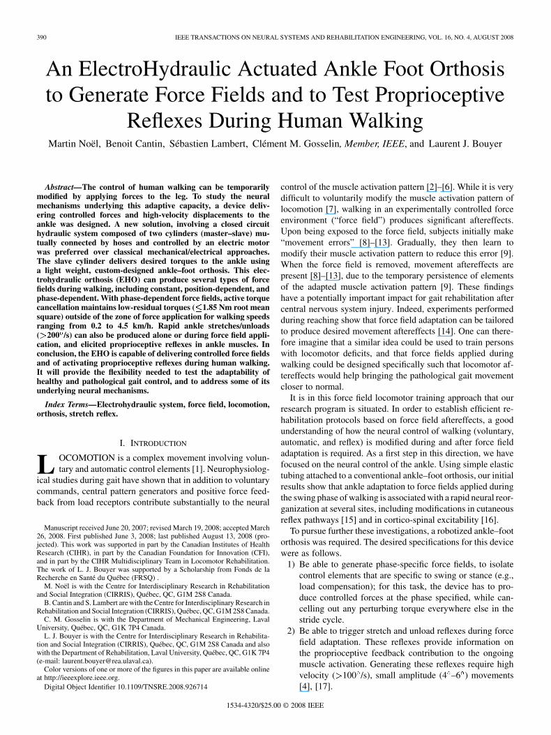
Fig. 2. Schematic view of the four bar mechanism of the drive system and ofthe ankle–foot orthosis. L3 and L6 represent the master and slave cylinders,respectively. The ratio of r =r stays between 0.99 and 1.02 when � remainsbetween �30 and 15 .
placed around the shoe are used to minimize movements of thefoot within the shoe during walking.
F. Safety Elements
To limit the range of ankle movements, mechanical stops(adjustable to individual maximal voluntary dorsi and plantarflexion) and optical encoder-based software stops are used. Tolimit maximal torque, a torque limiting clutch (adjusting max-imal motor output between 30 and 60 Nm) and load cell sig-nals (max 20 Nm at the ankle) are used. Finally, emergency stopswitches are located near the subject and near the operator.
G. Control System
Control is operated through a dedicated QNX OS-based real-time computer using custom software written in Simulink andrunning at a step size of 500 s. A classical PID controller isused to control the system. No feed forward or predictive controlis implemented in this first prototype. The force delivered by theorthosis is measured by a load cell (range 0–22.67 kg), located inseries with the slave cylinder. The measurement of the orthosisjoint angle ( ; cf. Fig. 2) by an optical encoder provides thegeometrical configuration of the orthosis, and is also used todetermine the length of the orthosis effective lever arm. Theapplied torque is calculated by multiplying the measured forcewith this lever arm. The system can be controlled using eithertorque (load cell) or position (optical encoder) feedback througha software switch. During torque control, the output of the PIDcontroller is multiplied by (cf. Fig. 2) to take into accountthe changes in the lever arm of the drive system over the stridecycle.
H. Geometric Configuration
Fig. 2 presents a schematic view of the drive system and ofthe orthosis, together with the variables used to describe thesystem’s geometry.
The force applied by the electric motor on the master cylinder,noted , can be written as
(1)
where represents the motor torque and where the effectivelever arm is a function of the system’s geometry that can beexpressed as
(2)
Variables , , , , , , and are defined, as shownin Fig. 2. Since the system has only 1 egree-of-freedom in ro-tation, all variables can be expressed as a function of . The re-lationship between the drive system and the orthosis is the dis-placement of the cylinders. Assuming that the compressibilityis negligible, the displacement of each cylinder is of the samemagnitude, but in opposite direction, namely, .To be compatible with the convention used in gait, is set to zerowhen the lateral uprights are perpendicular with the footplate. Atthis initial condition, , , and , where
, , and depend on the orthosis design. The length of themaster cylinder, noted , can be expressed by its initial value
plus the variation of length caused by the displacement ofthe orthosis , namely
(3)
Using the law of cosines, the length of the slave cylinder,noted , can be calculated as
(4)
Moreover, angle can be written as
(5)
The length of the master cylinder can be expressed as afunction of as
(6)
Using the law of cosines, angle can be expressed as a func-tion of as
(7)
where represents the angle between the bars of length and, respectively.Substituting (2) into (1), one obtains
(8)
and finally, substituting (7) into (8), the force applied on themaster cylinder by the electric motor can also be expressedas a function of .
The magnitude of the torque applied on the ankle of the sub-ject can be computed as
(9)
where represents the force generated by the slave cylinderand represents the effective lever arm of the orthosis. These
NOËL et al.: AN ELECTROHYDRAULIC ACTUATED ANKLE FOOT ORTHOSIS TO GENERATE FORCE FIELDS 393
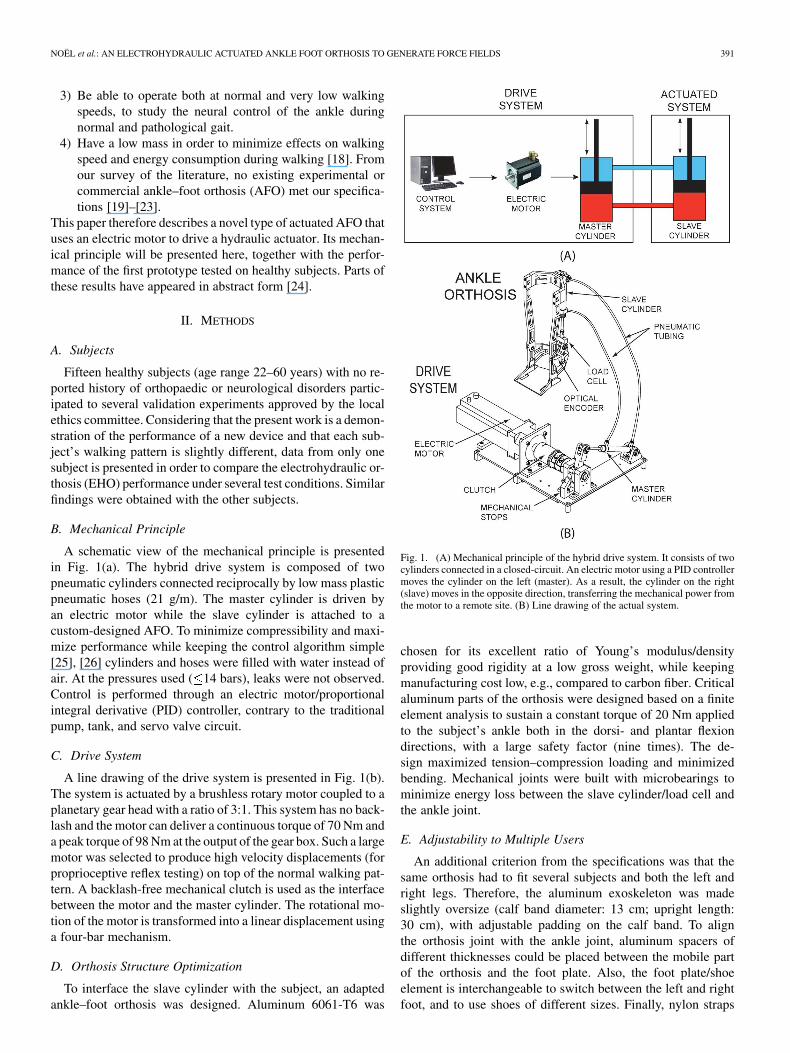
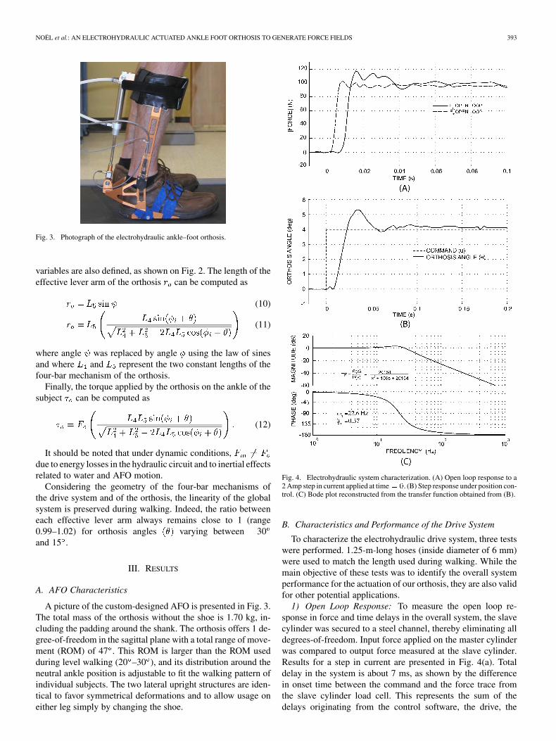
Fig. 3. Photograph of the electrohydraulic ankle–foot orthosis.
variables are also defined, as shown on Fig. 2. The length of theeffective lever arm of the orthosis can be computed as
(10)
(11)
where angle was replaced by angle using the law of sinesand where and represent the two constant lengths of thefour-bar mechanism of the orthosis.
Finally, the torque applied by the orthosis on the ankle of thesubject can be computed as
(12)
It should be noted that under dynamic conditions,due to energy losses in the hydraulic circuit and to inertial effectsrelated to water and AFO motion.
Considering the geometry of the four-bar mechanisms ofthe drive system and of the orthosis, the linearity of the globalsystem is preserved during walking. Indeed, the ratio betweeneach effective lever arm always remains close to 1 (range0.99–1.02) for orthosis angles varying between 30and 15 .
III. RESULTS
A. AFO Characteristics
A picture of the custom-designed AFO is presented in Fig. 3.The total mass of the orthosis without the shoe is 1.70 kg, in-cluding the padding around the shank. The orthosis offers 1 de-gree-of-freedom in the sagittal plane with a total range of move-ment (ROM) of 47 . This ROM is larger than the ROM usedduring level walking (20 –30 ), and its distribution around theneutral ankle position is adjustable to fit the walking pattern ofindividual subjects. The two lateral upright structures are iden-tical to favor symmetrical deformations and to allow usage oneither leg simply by changing the shoe.
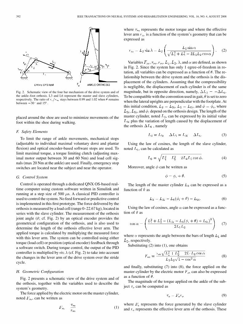
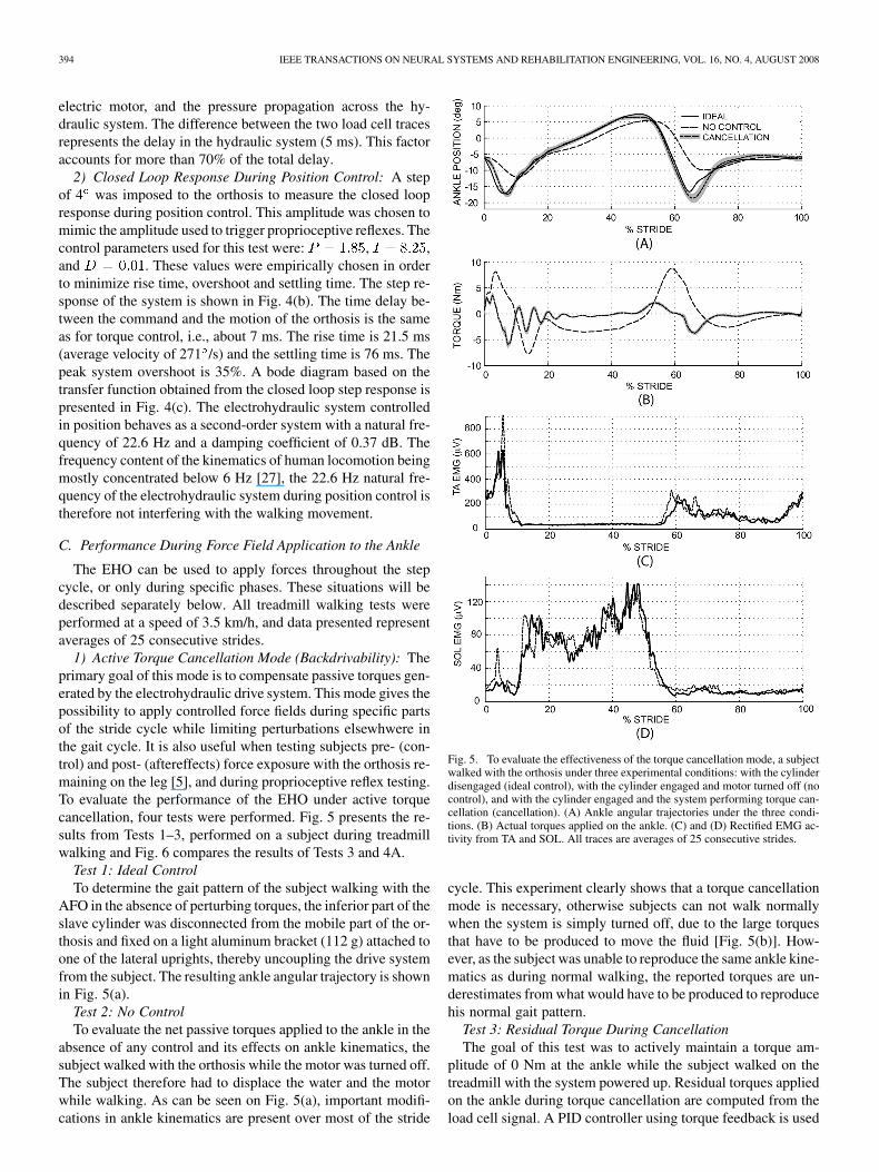
Fig. 4. Electrohydraulic system characterization. (A) Open loop response to a2 Amp step in current applied at time = 0. (B) Step response under position con-trol. (C) Bode plot reconstructed from the transfer function obtained from (B).
B. Characteristics and Performance of the Drive System
To characterize the electrohydraulic drive system, three testswere performed. 1.25-m-long hoses (inside diameter of 6 mm)were used to match the length used during walking. While themain objective of these tests was to identify the overall systemperformance for the actuation of our orthosis, they are also validfor other potential applications.
1) Open Loop Response: To measure the open loop re-sponse in force and time delays in the overall system, the slavecylinder was secured to a steel channel, thereby eliminating alldegrees-of-freedom. Input force applied on the master cylinderwas compared to output force measured at the slave cylinder.Results for a step in current are presented in Fig. 4(a). Totaldelay in the system is about 7 ms, as shown by the differencein onset time between the command and the force trace fromthe slave cylinder load cell. This represents the sum of thedelays originating from the control software, the drive, the
394 IEEE TRANSACTIONS ON NEURAL SYSTEMS AND REHABILITATION ENGINEERING, VOL. 16, NO. 4, AUGUST 2008
electric motor, and the pressure propagation across the hy-draulic system. The difference between the two load cell tracesrepresents the delay in the hydraulic system (5 ms). This factoraccounts for more than 70% of the total delay.
2) Closed Loop Response During Position Control: A stepof 4 was imposed to the orthosis to measure the closed loopresponse during position control. This amplitude was chosen tomimic the amplitude used to trigger proprioceptive reflexes. Thecontrol parameters used for this test were: , ,and . These values were empirically chosen in orderto minimize rise time, overshoot and settling time. The step re-sponse of the system is shown in Fig. 4(b). The time delay be-tween the command and the motion of the orthosis is the sameas for torque control, i.e., about 7 ms. The rise time is 21.5 ms(average velocity of 271 /s) and the settling time is 76 ms. Thepeak system overshoot is 35%. A bode diagram based on thetransfer function obtained from the closed loop step response ispresented in Fig. 4(c). The electrohydraulic system controlledin position behaves as a second-order system with a natural fre-quency of 22.6 Hz and a damping coefficient of 0.37 dB. Thefrequency content of the kinematics of human locomotion beingmostly concentrated below 6 Hz [27], the 22.6 Hz natural fre-quency of the electrohydraulic system during position control istherefore not interfering with the walking movement.
C. Performance During Force Field Application to the Ankle
The EHO can be used to apply forces throughout the stepcycle, or only during specific phases. These situations will bedescribed separately below. All treadmill walking tests wereperformed at a speed of 3.5 km/h, and data presented representaverages of 25 consecutive strides.
1) Active Torque Cancellation Mode (Backdrivability): Theprimary goal of this mode is to compensate passive torques gen-erated by the electrohydraulic drive system. This mode gives thepossibility to apply controlled force fields during specific partsof the stride cycle while limiting perturbations elsewhwere inthe gait cycle. It is also useful when testing subjects pre- (con-trol) and post- (aftereffects) force exposure with the orthosis re-maining on the leg [5], and during proprioceptive reflex testing.To evaluate the performance of the EHO under active torquecancellation, four tests were performed. Fig. 5 presents the re-sults from Tests 1–3, performed on a subject during treadmillwalking and Fig. 6 compares the results of Tests 3 and 4A.
Test 1: Ideal ControlTo determine the gait pattern of the subject walking with the
AFO in the absence of perturbing torques, the inferior part of theslave cylinder was disconnected from the mobile part of the or-thosis and fixed on a light aluminum bracket (112 g) attached toone of the lateral uprights, thereby uncoupling the drive systemfrom the subject. The resulting ankle angular trajectory is shownin Fig. 5(a).
Test 2: No ControlTo evaluate the net passive torques applied to the ankle in the
absence of any control and its effects on ankle kinematics, thesubject walked with the orthosis while the motor was turned off.The subject therefore had to displace the water and the motorwhile walking. As can be seen on Fig. 5(a), important modifi-cations in ankle kinematics are present over most of the stride
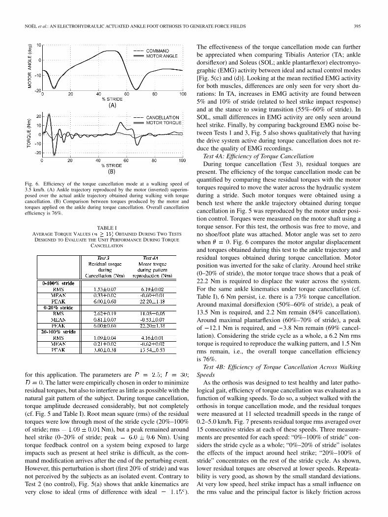
Fig. 5. To evaluate the effectiveness of the torque cancellation mode, a subjectwalked with the orthosis under three experimental conditions: with the cylinderdisengaged (ideal control), with the cylinder engaged and motor turned off (nocontrol), and with the cylinder engaged and the system performing torque can-cellation (cancellation). (A) Ankle angular trajectories under the three condi-tions. (B) Actual torques applied on the ankle. (C) and (D) Rectified EMG ac-tivity from TA and SOL. All traces are averages of 25 consecutive strides.
cycle. This experiment clearly shows that a torque cancellationmode is necessary, otherwise subjects can not walk normallywhen the system is simply turned off, due to the large torquesthat have to be produced to move the fluid [Fig. 5(b)]. How-ever, as the subject was unable to reproduce the same ankle kine-matics as during normal walking, the reported torques are un-derestimates from what would have to be produced to reproducehis normal gait pattern.
Test 3: Residual Torque During CancellationThe goal of this test was to actively maintain a torque am-
plitude of 0 Nm at the ankle while the subject walked on thetreadmill with the system powered up. Residual torques appliedon the ankle during torque cancellation are computed from theload cell signal. A PID controller using torque feedback is used
NOËL et al.: AN ELECTROHYDRAULIC ACTUATED ANKLE FOOT ORTHOSIS TO GENERATE FORCE FIELDS 395
Fig. 6. Efficiency of the torque cancellation mode at a walking speed of3.5 km/h. (A) Ankle trajectory reproduced by the motor (inverted) superim-posed over the actual ankle trajectory obtained during walking with torquecancellation. (B) Comparison between torques produced by the motor andtorques applied on the ankle during torque cancellation. Overall cancellationefficiency is 76%.
TABLE IAVERAGE TORQUE VALUES (n � 15) OBTAINED DURING TWO TESTS
DESIGNED TO EVALUATE THE UNIT PERFORMANCE DURING TORQUE
CANCELLATION
for this application. The parameters are ; ;. The latter were empirically chosen in order to minimize
residual torques, but also to interfere as little as possible with thenatural gait pattern of the subject. During torque cancellation,torque amplitude decreased considerably, but not completely(cf. Fig. 5 and Table I). Root mean square (rms) of the residualtorques were low through most of the stride cycle (20%–100%of stride; rms Nm), but a peak remained aroundheel strike (0–20% of stride; peak Nm). Usingtorque feedback control on a system being exposed to largeimpacts such as present at heel strike is difficult, as the com-mand modification arrives after the end of the perturbing event.However, this perturbation is short (first 20% of stride) and wasnot perceived by the subjects as an isolated event. Contrary toTest 2 (no control), Fig. 5(a) shows that ankle kinematics arevery close to ideal (rms of difference with ideal ).
The effectiveness of the torque cancellation mode can furtherbe appreciated when comparing Tibialis Anterior (TA; ankledorsiflexor) and Soleus (SOL; ankle plantarflexor) electromyo-graphic (EMG) activity between ideal and actual control modes[Fig. 5(c) and (d)]. Looking at the mean rectified EMG activityfor both muscles, differences are only seen for very short du-rations: In TA, increases in EMG activity are found between5% and 10% of stride (related to heel strike impact response)and at the stance to swing transition (55%–60% of stride). InSOL, small differences in EMG activity are only seen aroundheel strike. Finally, by comparing background EMG noise be-tween Tests 1 and 3, Fig. 5 also shows qualitatively that havingthe drive system active during torque cancellation does not re-duce the quality of EMG recordings.
Test 4A: Efficiency of Torque CancellationDuring torque cancellation (Test 3), residual torques are
present. The efficiency of the torque cancellation mode can bequantified by comparing these residual torques with the motortorques required to move the water across the hydraulic systemduring a stride. Such motor torques were obtained using abench test where the ankle trajectory obtained during torquecancellation in Fig. 5 was reproduced by the motor under posi-tion control. Torques were measured on the motor shaft using atorque sensor. For this test, the orthosis was free to move, andno shoe/foot plate was attached. Motor angle was set to zerowhen . Fig. 6 compares the motor angular displacementand torques obtained during this test to the ankle trajectory andresidual torques obtained during torque cancellation. Motorposition was inverted for the sake of clarity. Around heel strike(0–20% of stride), the motor torque trace shows that a peak of22.2 Nm is required to displace the water across the system.For the same ankle kinematics under torque cancellation (cf.Table I), 6 Nm persist, i.e. there is a 73% torque cancellation.Around maximal dorsiflexion (50%–60% of stride), a peak of13.5 Nm is required, and 2.2 Nm remain (84% cancellation).Around maximal plantarflexion (60%–70% of stride), a peakof 12.1 Nm is required, and 3.8 Nm remain (69% cancel-lation). Considering the stride cycle as a whole, a 6.2 Nm rmstorque is required to reproduce the walking pattern, and 1.5 Nmrms remain, i.e., the overall torque cancellation efficiencyis 76%.
Test 4B: Efficiency of Torque Cancellation Across WalkingSpeeds
As the orthosis was designed to test healthy and later patho-logical gait, efficiency of torque cancellation was evaluated as afunction of walking speeds. To do so, a subject walked with theorthosis in torque cancellation mode, and the residual torqueswere measured at 11 selected treadmill speeds in the range of0.2–5.0 km/h. Fig. 7 presents residual torque rms averaged over15 consecutive strides at each of these speeds. Three measure-ments are presented for each speed: “0%–100% of stride” con-siders the stride cycle as a whole; “0%–20% of stride” isolatesthe effects of the impact around heel strike; “20%–100% ofstride” concentrates on the rest of the stride cycle. As shown,lower residual torques are observed at lower speeds. Repeata-bility is very good, as shown by the small standard deviations.At very low speed, heel strike impact has a small influence onthe rms value and the principal factor is likely friction across
396 IEEE TRANSACTIONS ON NEURAL SYSTEMS AND REHABILITATION ENGINEERING, VOL. 16, NO. 4, AUGUST 2008
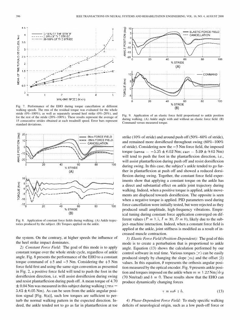
Fig. 7. Performance of the EHO during torque cancellation at differentwalking speeds. The rms of the residual torque was evaluated for the wholestride (0%–100%), as well as separately around heel strike (0%–20%), andfor the rest of the stride (20%–100%). These results represent the average of15 consecutive strides obtained at each treadmill speed. Error bars representstandard deviations.
Fig. 8. Application of constant force fields during walking. (A) Ankle trajec-tories produced by the subject. (B) Torques applied on the ankle.
the system. On the contrary, at higher speeds the influence ofthe heel strike impact dominates.
2) Constant Force Field: The goal of this mode is to applyconstant torque over the whole stride cycle, regardless of ankleangle. Fig. 8 presents the performance of the EHO to a constanttorque command of 5 and 5 Nm. Considering the 5 Nmforce field first and using the same sign convention as presentedin Fig. 2, a positive force field will tend to push the foot in thedorsiflexion direction, i.e. will assist dorsiflexion during swingand resist plantarflexion during push off. A mean torque of 4.70
0.04 Nm was measured in this subject during walkingNm . As can be seen from the ankle angular posi-
tion signal [Fig. 8(a)], such low torques are sufficient to per-turb the normal walking pattern in the expected direction. In-deed, the ankle tended not to go as far in plantarflexion at toe
Fig. 9. Application of an elastic force field proportional to ankle positionduring walking. (A) Ankle angle with and without an elastic force field. (B)Command versus measured torque.
strike (10% of stride) and around push off (50%–60% of stride),and remained more dorsiflexed throughout swing (60%–100%of stride). Considering now the 5 Nm force field, the imposedtorque ( Nm; Nm)will tend to push the foot in the plantarflexion direction, i.e.,will assist plantarflexion during push off and resist dorsiflexionduring swing. In this case, the subject’s ankle tended to go fur-ther in plantarflexion at push off and showed a reduced dorsi-flexion during swing. Together, the constant force field exper-iments show that applying a constant torque on the ankle hasa direct and substantial effect on ankle joint trajectory duringwalking. Indeed, when a positive torque is applied, ankle move-ments are displaced towards dorsiflexion. The opposite is seenwhen a negative torque is applied. PID parameters used duringforce cancellation were initially tested, but were rejected as theyproduced small amplitude, high-frequency vibrations. Empir-ical tuning during constant force application converged on dif-ferent values ( , , ), likely due to the sub-ject–machine interaction. Indeed, when a constant force field isapplied at the ankle, joint stiffness is modified as a result of in-creased muscle contraction.
3) Elastic Force Field (Position-Dependent): The goal of thismode is to create a perturbation that is proportional to ankleangle. Equation (13) shows the calculation performed by ourcontrol software in real time. Various torques can be easilyproduced simply by changing the slope and the offsetvalues. In this equation, represents the orthosis angular posi-tion measured by the optical encoder. Fig. 9 presents ankle posi-tion and torques imposed on the ankle when Nm(70 Nm/rad) and . These results show that the EHO canproduce dynamically changing forces
(13)
4) Phase-Dependent Force Field: To study specific walkingdeficits of neurological origin, such as a low push-off force or

NOËL et al.: AN ELECTROHYDRAULIC ACTUATED ANKLE FOOT ORTHOSIS TO GENERATE FORCE FIELDS 397
Fig. 10. Combining active torque cancellation with a brief torque applicationallows for the production of phase-dependent force fields. (A) Angular posi-tion of the ankle. (B) Ankle torque produced by the EHO for a force resistingpush-off (50% of stride for 100 ms; 10 Nm peak).
foot-drop, it is necessary to apply force fields only during prede-termined phases of the stride cycle, while using torque cancel-lation the rest of the time. Fig. 10 presents an example where a10-Nm force field resisting push-off was applied. The resultingtorque is present only between 50% and 60% of stride. This ex-periment shows that the EHO can therefore smoothly transitionbetween two force commands. Looking at the effects on ankletrajectory, it can be seen that the change in direction from dor-siflexion towards plantar flexion is delayed, as expected (55%instead of 50% of stride).
D. Using the Robotized Orthosis to Test ProprioceptiveReflexes
To evoke proprioceptive reflexes, the EHO had to deliverrapid changes in ankle angular position, and to maintain thefinal position during a short period of time to simplify reflexmeasurement. For this control mode, a temporary switch fromtorque to position control was implemented in the controlsoftware to produce the same “perturbation-and-hold” profileregardless of the moment of occurrence in the stride cycle. Tominimize the influence of the EHO on the walking pattern,torque cancellation (under torque control) is used when noreflex is evoked. Switching between the two modes of controloccurs within one time step (500 ). Parameters for positioncontrol were ; ; (empiricallytuned). Fig. 11 shows ankle angular position and surface elec-tromyographic signals from SOL and TA when a 4 stretch orunload of ankle plantarflexors is produced 350 ms after heelstrike. The perturbation is followed by a 200 ms hold period.For comparison, control walking is also superimposed. Consid-ering the stretch response first, a 4.3 angular displacement isproduced by the EHO, at an average velocity of 220 /s. Thisresponse is in the same range, as reported by others [4], [17].As a result of this brief controlled perturbation, two responsesare observed in the SOL EMG, at 38 and 70 ms, correspondingto the short latency (SLR) and middle latency responses (MLR;
Fig. 11. Examples of responses in Soleus EMG obtained after a stretch or un-load and 200 ms hold perturbation applied during walking. Control and pertur-bations are superimposed for comparison. Vertical dashed lines represent onsetand end of perturbation. Inset represents a time expanded window synchronizedon perturbation onset. Both stretch and unload responses can be clearly iden-tified, demonstrating the ability of the EHO to trigger proprioceptive reflexesduring locomotion.
[17]). Considering now the unload response, a 4.8 angulardisplacement in the plantarflexion direction is produced, rapidlyunloading the SOL muscle at an average velocity of 224 /s. Asa result, a drop in Soleus EMG activity is observed 51 ms afterthe unload onset. Again, this value fits well within the reportedlatencies of Grey et al. [17]. The size of the EMG responsesto stretch and unload are sufficiently different from baselinelocomotor EMG to allow for a reliable discrimination, with aclear onset. The EHO is therefore also capable of triggeringproprioceptive reflexes. No degradation in performance wasmeasured when reflexes were tested with force fields appliedto the ankle: stretch velocities were 208 /s and 235 /s whenapplied during a 3 or 3 Nm constant force field, respectively(data not shown).
IV. DISCUSSION
This orthosis was designed to study the adaptive capacity ofhuman locomotion when walking is challenged by different forcefield environments. The main objective was to build a system ca-pable of applying force fields either continuously or only duringpredetermined phases of the stride cycle. A hybrid solution con-sisting of an electric motor coupled to a closed-loop, water-filleddual cylinder system was selected, as it provided good force andposition control over more than 80% of the stride cycle. Theelectric motor being remote from the subject minimizes electro-magnetic interference during surface EMG recordings. Controlis simplified by the electric motor/PID controller. Finally, this
398 IEEE TRANSACTIONS ON NEURAL SYSTEMS AND REHABILITATION ENGINEERING, VOL. 16, NO. 4, AUGUST 2008
electrohydraulic system is able to work in both directions (ten-sion and compression). The chosen design therefore allowspushing and pulling with a single actuator. This option lowersweight and makes the device more compact. The weight limitspecification of 1.8 kg (shoe not included) for the orthosis wasbased on the study of Barnett et al. [18] that showed that from thisvalue and above, oxygen consumption significantly increasedand cadence decreased. In addition, the system can switch fromtorque to position control in real time. This ability, together withthe capacity to introduce small amplitude, high velocity displace-ments within the movement, provides the additional flexibilitynecessary to test stretch [4], [28] or unloading reflexes [5], [17]either during normal or during force field walking. Furthermore,in a rehabilitation context, position control could also be usedduring the early locomotor training phase to present a normalankle trajectory to the subject, with the possibility of switchingto resistive training later on. To go towards a more completeempowerment, intermittent force fields (i.e., present only onselected steps in a series) could also be implemented with onlyminor modifications to the control software.
A. Comparison With Existing Robotized AFOs
While other robotized AFOs already exist, none met ourdesired specifications, i.e., to produce good force controlduring the whole stride cycle AND to generate rapid “displace-and-hold” perturbations necessary to test proprioceptive re-flexes. The electrohydraulic orthosis (EHO) therefore presentsa combination of characteristics that make it a unique device. Itsability to be controlled in force make it comparable to Blaya’sorthosis [21], [22]. The latter uses a small electric motor todrive a series elastic actuator. This drive system is worn by thesubject, making it heavier than the EHO. In addition, the closeproximity of an electric motor with the shank muscles maycause electromagnetic interferences, that could interfer withthe measurement of surface electromyograms. The ability toproduce phase-dependent perturbations/assistance could alsohave been done using Ferris’ pneumatic muscle AFO [23].However, the latter is very difficult to control in force or inposition, as force generation varies significantly as a functionof length for a given air pressure [29], [30]. Finally, to studyproprioceptive reflexes, Sinkjaer’s AFO actuated by a remotemotor and Bowden wires is more rapid than the EHO to applysudden displacements (stretches and unloads) at the ankle [20].While this system was not initially designed for force control,it could probably be used in this mode. However, due to theuse of Bowden cables to transmit force from the motor to theorthosis, and due to the fact that these cables can only workin tension, this system is more prone to backlash effects at thechanges in movement/force direction.
The control algorithm that was used in the present study toproduce stretches/unloads involved switching from force to po-sition control in real time and applying rapid displacements.While the peak velocities reached are in the order of 200 /s com-pared to up to 500 /s with Sinkjaer’s device, the EHO was stillable to produce reliable reflex responses in the Soleus muscle,as did Yang and Stein with even lower velocities [4]. In the de-vices presented to this point, the electro-mechanical systemsused were very different from the EHO. Recently, Saito et al.
[31] presented a design related to that of the EHO, where anelectric motor was used to move hydraulic cylinders attached tothe leg in a closed-loop system. The design of Saito et al. slavecylinder was quite different from that of the EHO, however. Itconsists of a cylinder with two piston rods that replicates a biar-ticular muscle. While their machine was designed for a differentpurpose, i.e., to assist leg movement after spinal cord injury, thefact that these authors came to a similar mechanical solution inorder to control human walking widens the potential applica-tions of the hybrid approach.
V. CONCLUSION
In conclusion, the EHO described here combines characteris-tics that make it a unique system capable of applying controlledforce fields over a large range of walking speeds and of mea-suring proprioceptive reflexes before, during, and after exposureto such forces. This capacity comes from the hybrid solution thatcombines an electric motor with an hydraulic actuator. Throughalmost instantaneous switching between force and position con-trol, the PID controller can adjust to the experimenter’s demandsin real time. The EHO will provide new ways to address ques-tions regarding the control and the adaptability of human loco-motion. In the longer-term, the EHO may also be used to studyand train persons with locomotor deficits with very specific, im-pairment-related force fields.
ACKNOWLEDGMENT
The authors would like to thank Dr. H. El Makssoud for hissignificant contribution to the revision of the manuscript andD. Koslowski from Festo Canada for his technical support withthe customization of the cylinders.
REFERENCES
[1] A. E. Patla, “Neurobiomechanical bases for the control of humanlocomotion,” in Clinical Aspects of Balance and Gait Disorders, A.Bronstein, T. Brandt, and M. Woollacott, Eds. London: Arnold, pp.19–40A. E. Patla, “Neurobiomechanical bases for the control of humanlocomotion,” Clinical Aspects of Balance and Gait Disorders 1996, pp.1–40.
[2] A. Prochazka, D. Gillard, and D. J. Bennett, “Positive force feedbackcontrol of muscles,” J. Neurophysiol., vol. 77, no. 6, pp. 3226–3236,Jun. 1997.
[3] A. Prochazka, D. Gillard, and D. J. Bennett, “Implications of positivefeedback in the control of movement,” J. Neurophysiol., vol. 77, no. 6,pp. 3237–3251, Jun. 1997.
[4] J. F. Yang, R. B. Stein, and K. B. James, “Contribution of peripheralafferents to the activation of the soleus muscle during walking in hu-mans,” Exp. Brain Res., vol. 87, no. 3, pp. 679–687, 1991.
[5] M. J. Grey, J. B. Nielsen, N. Mazzaro, and T. Sinkjaer, “Positive forcefeedback in human walking,” J. Physiol., vol. 581, no. 1, pp. 99–105,Mar. 2007.
[6] V. Dietz and J. Duysens, “Significance of load receptor input duringlocomotion: A review,” Gait Posture, vol. 11, no. 2, pp. 102–110, Apr.2000.
[7] M. C. Wetzel and R. E. Wetzel, “Integration of learned and naturallyoccurring flexor EMG in the human step cycle,” Physiol. Behav., vol.38, no. 1, pp. 41–51, 1986.
[8] D. J. Reinkensmeyer, J. H. Wynne, and S. J. Harkema, “A robotic toolfor studying locomotor adaptation and rehabilitation,” in Proc. 2nd JoitEMBS/BMES Conf., Houston, TX, 2002, pp. 2353–2354.
[9] E. Tremblay and L. J. Bouyer, “Modifications of locomotor outputduring and after exposure to an elastic force applied to the leg,” Soc.Neurosci. Abstracts, 2003.
[10] L. J. Bouyer, P. DiZio, and J. R. Lackner, “Adaptive modification ofhuman locomotion by Coriolis force,” Soc. Neurosci. Abstracts, 2003.
NOËL et al.: AN ELECTROHYDRAULIC ACTUATED ANKLE FOOT ORTHOSIS TO GENERATE FORCE FIELDS 399
[11] J. L. Emken and D. J. Reinkensmeyer, “Robot-enhanced motorlearning: Accelerating internal model formation during locomotion bytransient dynamic amplification,” IEEE Trans. Neural Syst. Rehabil.Eng., vol. 13, no. 1, pp. 33–39, Mar. 2005.
[12] T. Lam, M. Anderschitz, and V. Dietz, “Contribution of feedback andfeedforward strategies to locomotor adaptations,” J. Neurophysiol., vol.95, no. 2, pp. 766–773, Feb. 2006.
[13] K. E. Gordon and D. P. Ferris, “Learning to walk with a robotic ankleexoskeleton,” J. Biomech., vol. 40, no. 12, pp. 2636–2644, 2007.
[14] J. L. Patton and F. A. Mussa-Ivaldi, “Robot-assisted adaptive training:Custom force fields for teaching movement patterns,” IEEE Trans.Biomed. Eng., vol. 51, no. 4, pp. 636–646, Apr. 2004.
[15] S. Alain, B. D. Cantin, and L. J. Bouyer, “Human cutaneous reflexeswhile walking in an elastic force field applied to the ankle,” Soc. Neu-rosci. Abstracts, 2005.
[16] S. Alain, D. Barthelemy, M. J. Grey, L. J. Bouyer, C. L. Richards, andJ. B. Nielsen, “Rapid, task-specific modifications of cortico-spinal ex-citability during adaptation of human locomotion to elastic force fieldsapplied to the ankle,” Soc. Neurosci. Abstracts, 2007.
[17] M. J. Grey, N. Mazzaro, J. B. Nielsen, and T. Sinkjaer, “Ankle ex-tensor proprioceptors contribute to the enhancement of the soleus EMGduring the stance phase of human walking,” Can. J. Physiol. Phar-macol., vol. 82, no. 8–9, pp. 610–616, Aug. 2004.
[18] S. L. Barnett, A. M. Bagley, and H. B. Skinner, “Ankle weight ef-fect on gait: Orthotic implications,” Orthopedics, vol. 16, no. 10, pp.1127–1131, Oct. 1993.
[19] J. B. Andersen and T. Sinkjaer, “An actuator system for investigatingelectrophysiological and biomechanical features around the humanankle joint during gait,” IEEE Trans. Rehabil. Eng., vol. 3, no. 4, pp.299–306, Dec. 1995.
[20] J. B. Andersen and T. Sinkjaer, “Mobile ankle and knee perturbator,”IEEE Trans. Biomed. Eng., vol. 50, no. 10, pp. 1208–1211, Oct.2003.
[21] J. A. Blaya and H. Herr, “Adaptive control of a variable-impedanceankle-foot orthosis to assist drop-foot gait,” IEEE Trans. Neural Syst.Rehabil. Eng., vol. 12, no. 1, pp. 24–31, Mar. 2004.
[22] D. W. Robinson, J. E. Pratt, D. J. Paluska, and G. A. Pratt, “Serieselastic actuator development for a biomimetic walking robot,” inIEEE/ASME Int. Conf. Adv. Intell. Mechatron., Sep. 19–22, 1999, pp.561–568.
[23] D. P. Ferris, J. M. Czerniecki, and B. Hannaford, “An ankle-foot or-thosis powered by artificial pneumatic muscles,” J. Appl. Biomech., vol.21, no. 2, pp. 189–197, May 2005.
[24] M. Noel, B. D. Cantin, C. M. Gosselin, and L. J. Bouyer, “Anelectrohydraulic actuated ankle orthosis to generate force fieldsand to test stretch reflexes during human walking,” Soc. Neurosci.Abstracts, 2006.
[25] E. Richer and Y. Hurmuzlu, “A high performance pneumatic forceactuator system, Part 1—Nonlinear mathematical model,” ASME J.Dynamic Syst. Measure. Control, vol. 122, no. 3, pp. 416–425,2000.
[26] E. Richer and Y. Hurmuzlu, “A high performance pneumatic force ac-tuator system, Part 2—Nonlinear controller design,” ASME J. DynamicSyst. Measure. Control, vol. 122, no. 3, pp. 426–434, 2000.
[27] D. A. Winter, Biomechanics and Motor Control of Human Movement,2nd ed. New York: Wiley-Interscience, 1990.
[28] T. Sinkjaer, J. B. Andersen, and B. Larsen, “Soleus stretch reflex mod-ulation during gait in humans,” J. Neurophysiol., vol. 76, no. 2, pp.1112–1120, Aug. 1996.
[29] J. H. Lilly, “Adaptive tracking for pneumatic muscle actuators in bicepand tricep configurations,” IEEE Trans. Neural Syst. Rehabil. Eng., vol.11, no. 3, pp. 333–339, Sep. 2003.
[30] K. E. Gordon, G. S. Sawicki, and D. P. Ferris, “Mechanical perfor-mance of artificial pneumatic muscles to power an ankle-foot orthosis,”J. Biomech., vol. 39, no. 10, pp. 1832–1841, 2006.
[31] Y. Saito, K. Kikuchi, H. Negoto, T. Oshima, and T. Haneyochi, “Devel-opment of externally powered lower limb orthosis with bilateral-servoactuator,” in Proc. IEEE 9th Int. Conf. Rehabil. Robot., Chicago, IL,2005, pp. 394–399.
Martin Noël received the B.Eng. and M.Sc. degreesin mechanical engineering from Laval University,Québec City, QC, Canada, in 2004 and 2007,respectively.
He is currently with the CIRRIS in Research andDevelopment.
Benoit Cantin received the B.Eng. degree in elec-trical engineering and the M.Sc. degree in mechan-ical engineering from Laval University, Québec City,QC, Canada, in 2002 and 2004, respectively.
Sébastien Lambert is currently working toward theM.D. degree at Laval University, Québec City, QC,Canada.
Clément M. Gosselin (M’88) received the B.Eng.degree in mechanical engineering from the Univer-sité de Sherbrooke, Québec, QC, Canada, in 1985 andthe Ph.D. degree from McGill University, Montréal,QC, Canada, in 1988.
He is currently a Professor of Mechanical En-gineering at Laval University, Québec City, QC,Canada, where he is holding a Canada ResearchChair in Robotics and Mechatronics. He is the authorof numerous publications and he has worked inresearch laboratories in France and in Germany.
Dr. Gosselin is a member of CCToMM as well as a Fellow of the ASME.
Laurent J. Bouyer received B.Sc. (honors) and thePh.D. degree in physiology from McGill University,Montréal, QC, Canada, in 1990 and 1996, respec-tively. He then completed a fellowship at the Centerfor Neurological Science Research at the Universityof Montréal, Montréal, QC, Canada, in 2002.
He is currently an Associate Professor in theDepartment of Rehabilitation at Laval University,Quebéc City, QC, Canada. His research interestsin the neural plasticity of the control of humanlocomotion include the development of new devices
to improve locomotor recovery and the study of neural mechanisms underlyinglocomotor adaptation in healthy and pathological populations.
Related Documents