(IJACSA) International Journal of Advanced Computer Science and Applications, Vol. 12, No. 2, 2021 347 | Page www.ijacsa.thesai.org An Efficient Color LED Driver based on Self-Configuration Current Mirror Circuit Shaheer Shaida Durrani 1 , Abu Zaharin Bin Ahmad 2 , Bakri Bin Hassan 3 , Atif Sardar Khan 4 , Asif Nawaz 5 , Naveed Jan 6 Rehan Ali Khan 7 , Rohi Tariq 8 , Ahmed Ali Shah 9 , Tariq Bashir 10 , Zia Ullah Khan 11 , Sheeraz Ahmed 12 Faculty of Electrical & Electronics Engineering Technology, University Malaysia Pahang, Pekan, Malaysia 1, 2, 3 US-Pak Centre for Advanced Studies, In Energy (USPCAS-E), UET Peshawar, Pakistan 4 Faculty of Electronics, Higher Colleges of Technology, Dubai, UAE 5 Department of Information Engg Tech, University of Technology, Nowshera, Pakistan 6 Department of Electrical Engineering, University of Science and Technology, Bannu, Pakistan 7 School of Information and Technology (SIT), King Mongkut’s University of Technology, Thonburi, 10140, Bangkok, Thailand 8 Department of Electrical Engineering, Sukkur IBA University, Sukkur, Pakistan 9 Department of Electrical Engineering, COMSATS University, Islamabad, Pakistan 10 Manager Network Systems, Directorate of Science and Technology, Government of KPK, Pakistan 11 Department of Computer Science, Iqra National University, Peshawar, Pakistan 12 Abstract—The string channel of Color LED driver with precise current balancing is proposed. It is noted that to drive a multiple LEDs string is by using a proper current source, due to the level of the brightness LED depends on the quantity of the current flows. In the production of LEDs, the variation in the forward voltage for each LED has been found significantly high. This variation causes different levels of brightness in LEDs. Then, controlling load current of LED by using a resistor to limit the LED current flowing is considered by associated with the forward voltage, instantly. Current sources have been designed to become immune to the above problem since it regulates the current, and not the voltage which flows through the LEDs. Hence, constant current source is the essential requirement to drive the LEDs. Besides, it is complex for color LEDs, dependent on the number of control nodes and dimming configuration. To arrange an accurate load current for the different sets of string color LEDs, the efficient LED driver is required, in which the current sharing is complement to each LED strings. Therefore, this paper suggests a color LED driver with self-configuration of enhanced current mirrors in multiple LED strings. The load currents have been efficiently balanced among the identical loads and unequal loads. The comparable efficiency of the string color LEDs losses has been shown thoroughly. Keywords—Color LED driver; current mirror circuit; super diode I. INTRODUCTION Nowadays, light-emitting diode (LEDs) has gradually replaced the lighting system due to better luminous, affordable size, energy-saving, and nature friendly [1]. Nonetheless, the constant output current for reliable LEDs driver is vital to ensure a good performance of LEDs. For color LEDs, the balancing for current sharing through the string of red, green, or blue is crucial for avoiding blackout from a single LED fault due to an excessive driving voltage; hence the parallel string arrangement is preferred. Besides, it works with the LED driver to provide equivalent current to each string to make it sure to have uniform brightness. The inherent imbalance current flow could occur due to the LED forward voltage spread. Parallel channel connections of the LEDs create current differences among the LED strings due to their characteristic deviations. These deviations reduce the life cycles of the LEDs by introducing thermal spotting at a particular point. They also raise the matter of non- uniform luminance from the LEDs. To increase efficiency and simplicity, multichannel LED drivers are developed to replace single-channel LED drivers. Additionally, multichannel LED drivers can operate at different brightness for each individual LED channel. This enables lighting applications to be more optimized as compared to the use of single-channel LED drivers. Hence, this leads to advancements of multichannel selective dimming LED drivers. Parallel strings of the LEDs are frequently used in various embellishing, lighting, illustrating, and signaling purposes. The reliability of these circuits contains a significant factor, specifically in the field of backlighting system. Similar current values in each LED string are a crucial considered factor since it affects the reliability of the whole circuit. A small difference in current values in the strings has the potential to adversely affect the lifetime reliability and time span of the circuit. Since it is impractical to create identical devices, current balancing techniques have enormous importance for proper functioning of LED arrays. It has been observed that the most effective way of dealing with current imbalance is the utilization of current mirror (CM) techniques. Up to date, most of the drivers use a straightforward method as a common control supply to run LEDs which driven with independent sources of constant current [2]. In practical, color LEDs has a complex nature in a LED backlighting system, which depends upon the number of control nodes and LEDs requirement [2]. A switch-mode based power converter (SMPC) has been used for providing a steady current source to drive color LEDs. Nevertheless, it suffered from an intemperate control scattering in its series- pass devices [3]. A different utilization of driving color LEDs with numerous strings is being actualized for background brightening applications of LCD [3]. In this approach,

Welcome message from author
This document is posted to help you gain knowledge. Please leave a comment to let me know what you think about it! Share it to your friends and learn new things together.
Transcript
(IJACSA) International Journal of Advanced Computer Science and Applications,
Vol. 12, No. 2, 2021
347 | P a g e
www.ijacsa.thesai.org
An Efficient Color LED Driver based on
Self-Configuration Current Mirror Circuit
Shaheer Shaida Durrani1, Abu Zaharin Bin Ahmad
2, Bakri Bin Hassan
3, Atif Sardar Khan
4, Asif Nawaz
5, Naveed Jan
6
Rehan Ali Khan7, Rohi Tariq
8, Ahmed Ali Shah
9, Tariq Bashir
10, Zia Ullah Khan
11, Sheeraz Ahmed
12
Faculty of Electrical & Electronics Engineering Technology, University Malaysia Pahang, Pekan, Malaysia1, 2, 3
US-Pak Centre for Advanced Studies, In Energy (USPCAS-E), UET Peshawar, Pakistan4
Faculty of Electronics, Higher Colleges of Technology, Dubai, UAE5
Department of Information Engg Tech, University of Technology, Nowshera, Pakistan6
Department of Electrical Engineering, University of Science and Technology, Bannu, Pakistan7
School of Information and Technology (SIT), King Mongkut’s University of Technology, Thonburi, 10140, Bangkok, Thailand8
Department of Electrical Engineering, Sukkur IBA University, Sukkur, Pakistan9
Department of Electrical Engineering, COMSATS University, Islamabad, Pakistan10
Manager Network Systems, Directorate of Science and Technology, Government of KPK, Pakistan11
Department of Computer Science, Iqra National University, Peshawar, Pakistan12
Abstract—The string channel of Color LED driver with
precise current balancing is proposed. It is noted that to drive a
multiple LEDs string is by using a proper current source, due to
the level of the brightness LED depends on the quantity of the
current flows. In the production of LEDs, the variation in the
forward voltage for each LED has been found significantly high.
This variation causes different levels of brightness in LEDs.
Then, controlling load current of LED by using a resistor to limit
the LED current flowing is considered by associated with the
forward voltage, instantly. Current sources have been designed
to become immune to the above problem since it regulates the
current, and not the voltage which flows through the LEDs.
Hence, constant current source is the essential requirement to
drive the LEDs. Besides, it is complex for color LEDs, dependent
on the number of control nodes and dimming configuration. To
arrange an accurate load current for the different sets of string
color LEDs, the efficient LED driver is required, in which the
current sharing is complement to each LED strings. Therefore,
this paper suggests a color LED driver with self-configuration of
enhanced current mirrors in multiple LED strings. The load
currents have been efficiently balanced among the identical loads
and unequal loads. The comparable efficiency of the string color
LEDs losses has been shown thoroughly.
Keywords—Color LED driver; current mirror circuit; super
diode
I. INTRODUCTION
Nowadays, light-emitting diode (LEDs) has gradually replaced the lighting system due to better luminous, affordable size, energy-saving, and nature friendly [1]. Nonetheless, the constant output current for reliable LEDs driver is vital to ensure a good performance of LEDs. For color LEDs, the balancing for current sharing through the string of red, green, or blue is crucial for avoiding blackout from a single LED fault due to an excessive driving voltage; hence the parallel string arrangement is preferred. Besides, it works with the LED driver to provide equivalent current to each string to make it sure to have uniform brightness. The inherent imbalance current flow could occur due to the LED forward
voltage spread. Parallel channel connections of the LEDs create current differences among the LED strings due to their characteristic deviations. These deviations reduce the life cycles of the LEDs by introducing thermal spotting at a particular point. They also raise the matter of non- uniform luminance from the LEDs. To increase efficiency and simplicity, multichannel LED drivers are developed to replace single-channel LED drivers. Additionally, multichannel LED drivers can operate at different brightness for each individual LED channel. This enables lighting applications to be more optimized as compared to the use of single-channel LED drivers. Hence, this leads to advancements of multichannel selective dimming LED drivers. Parallel strings of the LEDs are frequently used in various embellishing, lighting, illustrating, and signaling purposes. The reliability of these circuits contains a significant factor, specifically in the field of backlighting system. Similar current values in each LED string are a crucial considered factor since it affects the reliability of the whole circuit. A small difference in current values in the strings has the potential to adversely affect the lifetime reliability and time span of the circuit. Since it is impractical to create identical devices, current balancing techniques have enormous importance for proper functioning of LED arrays. It has been observed that the most effective way of dealing with current imbalance is the utilization of current mirror (CM) techniques.
Up to date, most of the drivers use a straightforward method as a common control supply to run LEDs which driven with independent sources of constant current [2]. In practical, color LEDs has a complex nature in a LED backlighting system, which depends upon the number of control nodes and LEDs requirement [2]. A switch-mode based power converter (SMPC) has been used for providing a steady current source to drive color LEDs. Nevertheless, it suffered from an intemperate control scattering in its series-pass devices [3]. A different utilization of driving color LEDs with numerous strings is being actualized for background brightening applications of LCD [3]. In this approach,
(IJACSA) International Journal of Advanced Computer Science and Applications,
Vol. 12, No. 2, 2021
348 | P a g e
www.ijacsa.thesai.org
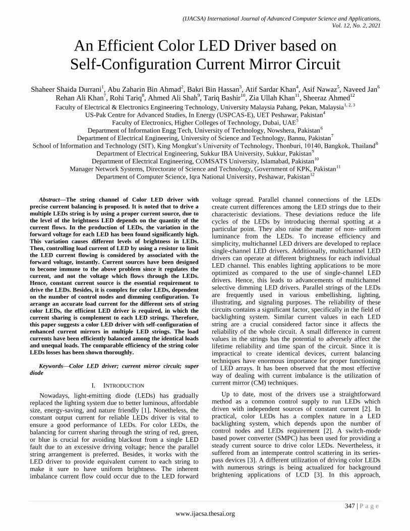
numerous current controllers have been utilized. As a result, significant improvement has been seen recently, for white power and high brightness (HB) LED technology [1], which made the usage of LED lighting sources to become prominent in most display application. Since the LED brightness coordinating current than voltage, the current balancing strategies which equalize the current through the string are vital [4]. Besides, the V-I characteristic of LEDs showing a considerable current change if a small diversity occurs in the voltage source to the LED. Since the color and brightness of LEDs are relying on the load current, hence, to avoid color shifting and to maintain the brightness concentration, the operations of color LEDs are recommended to be organized with a constant steady current. As in [5] and [6], demand always exists for compact and straightforward LED and color LED drivers. Nonetheless, current balancing of the color string LEDs contributes to the overall efficacy of the module LED loads or LED luminaires, rendering to maintain color produce and LEDs aging. Therefore, [7] had proposed the current mirror (CM) in solving the current imbalances among the LED strings with omitting an auxiliary source supply. It has shown significant improvement in maintaining the current balance in the string. However, separate source of supply to regulate the LEDs is required, which incline to the limitation and drawback of the existing CM. In addition, the LEDs display need to be turned on and off quicker than other lighting devices, hence the most appropriate current sharing circuit for the fast switching is desired. Therefore, the improvement circuit arrangement of CM has been suggested in this paper, which is also concerning the power dissipation through the string. Due to certain problems in the manufacturing process, LEDs have a problem with relatively large variations in the forward voltage (FV) characteristics [8]. These variables generate current-sharing problems, which differences between the load currents in rows of LEDs connected in a parallel fashion. This result does not permit the uniform distribution of the heat in the lighting, thus accelerating the aging of specific LEDs and getting luminance in a non-uniform manner. Eventually, the quality and the reliability of illumination of LED lighting devices would degrade. To resolve this problem, some suggestions have been suggested. The solutions can be classified into the method of using a linear regulator and CM in each row, converter for current control in each row, and by compensating the current error using a passive device in each row as discussed in Fig. 1(a) and (b). The balancing transformer is used in such applications for discharge lamps (CCFL, fluorescent lamps, etc.) as shown in Fig. 1(c). These lamps are run with the help of AC source, so a balancing transformer is directly applicable. However, for LEDs run through a DC source, the redesign of the circuit is necessary.
Therefore, in this article, a driving circuitry for parallel-connected color LEDs is presented, with the aiding of the current mirroring circuit. In this method, the suggested circuit can be reduced in size as compared to the conventional available design circuit. As a scope, a color LED driver has been proposed to drive 9 parallel-connected LEDs, consisting of either red, blue or green LEDs. The put forward driver has been designed to maintain the rock bottom drive voltage across the LEDs and its associated transistor (current
controller); leading to reduced power dissipation across the transistor, which eventually increased the efficiency of the particular LED string or set of LED strings. The suggested system of color LED driver is dimming capable for each individual LED through the controller circuit. Efficiencies have been verified at 97%, 98.55% for the red and green/blue, at the 21 mA and 22 mA, respectively. This paper starts with the discussion of limitations in the existing CM and then discussing the proposed CM circuit in section three. The rest follows the discussion of results and analysis.
(a) Current Mirror of Linear Regulator [3 ].
(b) DC/DC Converters [4].
(c) Passive Components and Diodes [8].
Fig. 1. Methods of Linear Regulator.
II. MOTIVATION
The existing CM approach needs a separate source of supply for regulating current at the LEDs as loads or in other words needs one fixed current source as a reference from separate power. In this approach, the reference is limited to the single load current only and the inability to allow predetermine the variations of the LED strings. As in [9 -13], traditional CM has a problem regulating loads strings of LEDs, while operating controlled current from low supply voltages. It becomes difficult to operate LEDs with minimal voltage, which results in operational demand for overhead
(IJACSA) International Journal of Advanced Computer Science and Applications,
Vol. 12, No. 2, 2021
349 | P a g e
www.ijacsa.thesai.org
voltage. The operational demand is required in handling the variations of the forward voltage drop across the loads, especially in mass-produced LED modules. Without the headroom voltage source, it becomes difficult to get equal currents parallel to the strings of LED loads. To address such limitations, a CM that works in a self-configurable mode has been proposed in [10]. The circuit’s operation depends upon a Darlington pair transistor, which has the ability to set the minimum current as the current reference to each string by closed-loop current control configuration. The Darlington transistors work in a linear region, to counter the differences of voltages between the bus of the dc voltage and the string voltage and do not need headroom voltage apparently, which suitable for LED backlight [11]. However, the driving currents, i.e. the base currents generating from the reference to bias the transistors, make the current replication imperfect even in the well-matched case which causes accuracy errors. This error increases with the number of strings, whereas its operation can be described with the following equation.
(1)
Where N shows the number of LED strings and denotes for target current. Since the LED current is almost corresponding to the LED's illumination, it is crucial to control the current precisely. In the event that all the LEDs are running in a single string, in series, there is no issue of mismatching since each LED has a similar current level. As the number of LEDs being used increases, resembling strings gets important, and a decision must be made with regards to how to control the current in each string. LEDs makers use binning to sort parts into bunches that precisely coordinate the LEDs forward voltage drops to permit execution. Conventionally, a fixed-voltage source and adding a straightforward resistor to set the current level has been done, but it costs to the efficiency drop. The loss of energy causes the output response of the LED to become slower. Secondly, the forward drop of voltages of the LEDs decreases with the increase of temperature. If somehow one channel or string gets significantly hotter due to any internal or external disturbing factor, its forward drop suddenly reduces and starts to draw huge current. This led to power dissipation in the form of heat. If disturbing factor is not removed, current will keep increasing and possibly lead LED to fail. Such situation needs that the applied voltage for driving currents in the strings is kept regulated. Thirdly, if an LED becomes open-circuited in the regulated string, the applied voltage energizing the strings is controlled by the control circuit and eventually causes overvoltage in the unregulated string, leading to failure. So, appropriate design is needed to avoid such issues. Furthermore, dimming is important factor in the effective control of lighting and in saving energy, but it faces various challenges. Getting full range of dimming means complete control of current passing through the LED. There are ways to energize color LEDs in the module system and the easiest way is to use respective constant current sources for each load i.e. string of LED or an LED [1]. This method looks easy, but it is costly and needs more components to the driver circuitry, which creates the whole system complex. Adding components simply means adding the possibilities of failure modes.
III. PROPOSED CURRENT MIRROR (CM)
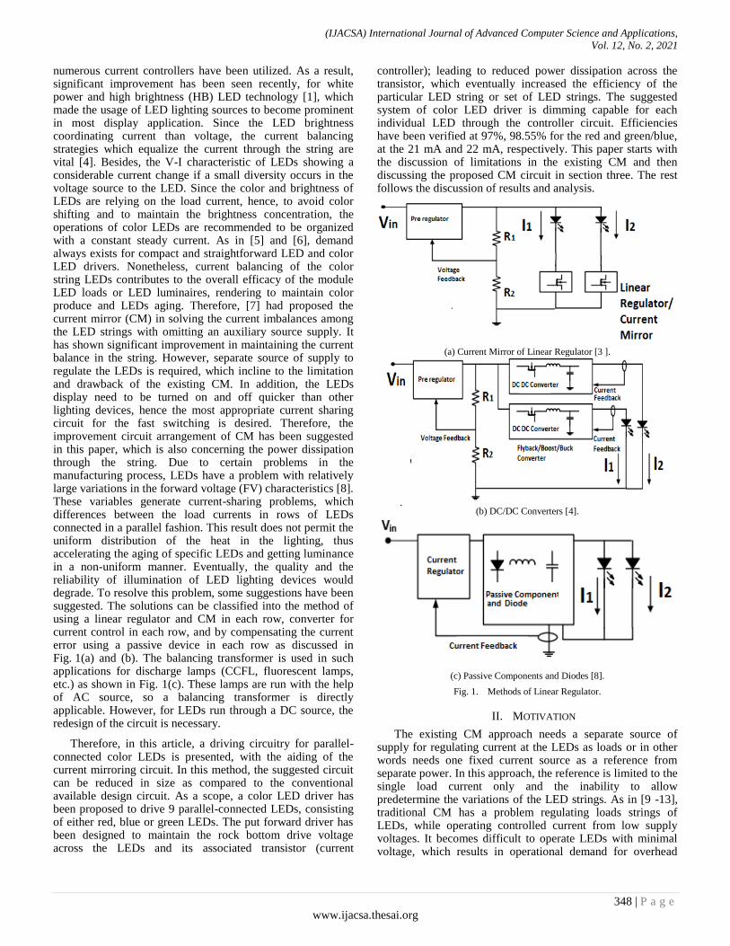
Two LED strings (two parallel-connected of color LEDs) are presented for ease of understanding for the proposed CM. The circuit can be extended to the number of strings. The buffer amplifier circuit with small magnitude is imposed as feedback requirement to replace the diode. The voltage drops across a small resistor decrease to the forward voltage drop, which is getting nearly zero when divided with the op-amp’s open-loop gain. The feedback mechanism of the op-amp has a feature of making voltage collector of transistor of the CM circuit equal to the voltage at the base, hence preventing the saturation from transistor. A negligible offset voltage occurs across the resistor. This condition is useful in improving CM’s circuit operation. Whereas the insignificant increase in the LED forward voltage at each string, creates a reference current for the entire proposed CM circuit. This proposed CM circuit is modular in nature and comprises of two main circuits, which are emitter-coupled logic (ECL) and super diode circuits are depicted in Fig. 2. In this approach, the circuit allows the CM to take the string's current as a reference current, in which the maximum voltage drop occurs in the string, as translated in Fig. 3. Furthermore, the resistors are series wise added at the outputs of the super diode circuits, which are further connected in series wise with the ECL transistors’ bases. In the conventional CM circuit, the transistor in each string operates like a couple of conjugated diodes which the forward biasing is required to turn on the diode due to base-emitter connection to activate the LEDs load on. It requires a minimum 0.6 V to activate which eventually increasing power loss. In that case, the enhancement of the CM by modification of the circuit is necessary. In the proposed CM circuit, the power losses are comparatively less than the improved Wilson CM circuit because the BJTs are not connected series wise in each string [5]. In implementation, the proposed CM circuit requires a closed control for superior execution, in which the DC-DC converter is utilized for feedback signal.
Fig. 2. Combinational Circuit of Super-Diode and ECL Circuit.
IV. MATHEMATICAL ANALYSIS
In evaluating the performances, the mathematical analysis is carried out. For the sake of simplicity analysis, only two leg strings are discussed. Refer to Fig. 2, suppose that LED string 1 has the lowest current branch, such that VCE1 is lower than VCE2. This phenomenon turns the super diode D1 on, and the associated op-amp feedback makes the Q1 transistor’s
(IJACSA) International Journal of Advanced Computer Science and Applications,
Vol. 12, No. 2, 2021
350 | P a g e
www.ijacsa.thesai.org
collector to has the same potential as the potential available for the transistor at its base, and the source of the supply voltage is maintained as;
(2)
The supply voltage does not have any headroom voltage element due to the nature of the ECL circuit, then the betas of the transistors are considered equal to each other such that;
(3)
Since the current goes through the LED string, connected to the proposed CM circuits are equal to each other, hence.
(4)
Finally, the power dissipation in each LED is represented as
(5)
Where, RLED_LOAD is a resistive load of the LEDs, Ion is the load current in the nth string, Vs denotes the supply voltage and VFORWARD is a LED forward voltage. As the PS_STRING is equal to the total of all the power developed across all the resistances of the devices in series, thus, the efficiency (ղ)
could be computed as follows.
(6)
where, is accumulative and losses across
the transistor. It has proved that the proposed circuit places no additional headroom voltage other than VCE or VBE during operating, the base of transistor becomes short and hence virtually a part of the transistor’s collector. Thus, the only power loss occurs in the string, develops across the collector and the emitter terminal of the transistor. This helps in having a proper biasing of the transistor circuit. As a result, the power loss across the transistor could be reduced to a significant extend.
The following readings have been noted experimentally, at 22.0 mA current for the red LED. In which, and
are computed 45.0 mW and 1.10 mW, respectively.
Thus, efficiency can be calculated as in the following.
= 97% (7)
Similar reading and calculations have been obtained for the blue LEDs in addition to the green LED. Since the blue LEDs besides the green LEDs have the same resistive characteristic, the reading is computed together at 21.0 mA. The and are calculated up to 69.62 mW and
1.02 mW, respectively. Hence, the efficiency is calculated to 98.55%.
V. DIMMING CONTROL MECHANISM
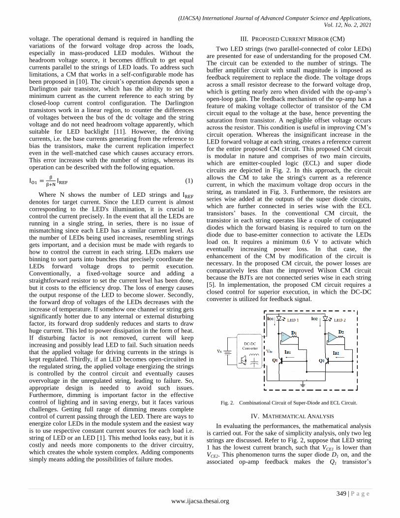
By obtaining the proper biasing, preventing the operation transistor to saturation, or in cut-off mode. This matter is engaged to the proper arrangement of dc collector current at a certain dc voltage by setting up a proper quiescent point as the circuit as discussed with the help of Fig. 3. At first, a base resistor ( ) is rearranged in the middle of collector and base
of the transistor due to the nature of the circuit does not allow base resistor connected to the supply. Hence, the connection between base and LEDs load is opted by tapped the shunt node in the middle of LEDs and collector transistors. Then, resistor R1 is located in the middle of the base and emitter for better biasing events which provided from the voltage developed across the R1.
Virtual resistance is a kind of resistance that does not present physically in the middle of the dimming circuit and the biasing circuit of the transistor. The dimming circuit creates various ground voltage references for the flow of load current from the biased transistor. Thus, by varying different voltage ground references, it is possible to create a kind of so-called virtual resistance in the path of flow of load current, in which no physical resistance is required. However, in this approach, the color LEDs module consists of a set of 9 color LEDs are configured, as shown in Fig. 4. Most of the LEDs dimming is controlled through PWM output by bringing change in the duty cycle. However, in this approach, the color LEDs module consist of a set of 9 color LEDs are configured. The supply comes from a DC-DC converter. Meanwhile, the dimming frequency is set to 1 kHz, where the dimming phenomenon is implemented at each leg of the CM circuits, in which the color LEDs are devised to be operated in individual dimming and overall diming. For ease computation, the power losses occur across the transistor are neglected.
As a result, the proposed CM associated with the dimming circuit possible to introduce a significant dimming level for single and whole LEDs in each string of color LEDs. While dimming occurs at certain LED loads, the associated transistor of the string reduces the current through the LED loads by raising the emitter’s voltage of the transistor that working with the ECL circuit. It eventually rises the collector’s voltage of the transistor which gives freedom to the LED load from the rest of the system which still running with a constant source of voltage. It is showing the proposed circuit topology could provide a constant load current with a dimming mechanism.
Fig. 3. Dimming Control Mechanism.
(IJACSA) International Journal of Advanced Computer Science and Applications,
Vol. 12, No. 2, 2021
351 | P a g e
www.ijacsa.thesai.org
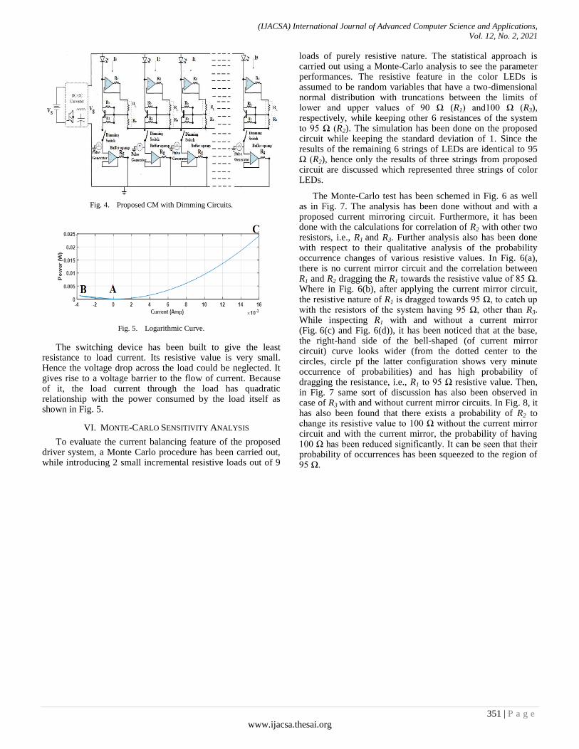
Fig. 4. Proposed CM with Dimming Circuits.
Fig. 5. Logarithmic Curve.
The switching device has been built to give the least resistance to load current. Its resistive value is very small. Hence the voltage drop across the load could be neglected. It gives rise to a voltage barrier to the flow of current. Because of it, the load current through the load has quadratic relationship with the power consumed by the load itself as shown in Fig. 5.
VI. MONTE-CARLO SENSITIVITY ANALYSIS
To evaluate the current balancing feature of the proposed driver system, a Monte Carlo procedure has been carried out, while introducing 2 small incremental resistive loads out of 9
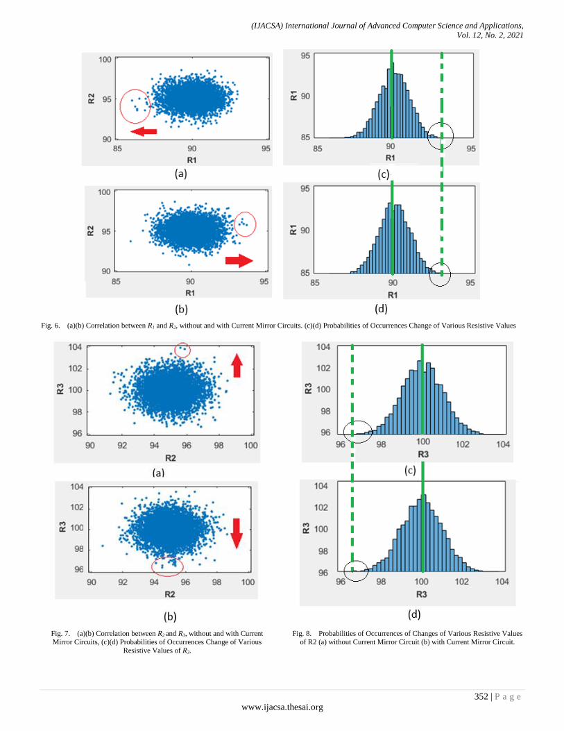
loads of purely resistive nature. The statistical approach is carried out using a Monte-Carlo analysis to see the parameter performances. The resistive feature in the color LEDs is assumed to be random variables that have a two-dimensional normal distribution with truncations between the limits of lower and upper values of 90 Ω (R1) and100 Ω (R3), respectively, while keeping other 6 resistances of the system to 95 Ω (R2). The simulation has been done on the proposed circuit while keeping the standard deviation of 1. Since the results of the remaining 6 strings of LEDs are identical to 95 Ω (R2), hence only the results of three strings from proposed circuit are discussed which represented three strings of color LEDs.
The Monte-Carlo test has been schemed in Fig. 6 as well as in Fig. 7. The analysis has been done without and with a proposed current mirroring circuit. Furthermore, it has been done with the calculations for correlation of R2 with other two resistors, i.e., R1 and R3. Further analysis also has been done with respect to their qualitative analysis of the probability occurrence changes of various resistive values. In Fig. 6(a), there is no current mirror circuit and the correlation between R1 and R2 dragging the R1 towards the resistive value of 85 Ω. Where in Fig. 6(b), after applying the current mirror circuit, the resistive nature of R1 is dragged towards 95 Ω, to catch up with the resistors of the system having 95 Ω, other than R3. While inspecting R1 with and without a current mirror (Fig. 6(c) and Fig. 6(d)), it has been noticed that at the base, the right-hand side of the bell-shaped (of current mirror circuit) curve looks wider (from the dotted center to the circles, circle pf the latter configuration shows very minute occurrence of probabilities) and has high probability of dragging the resistance, i.e., R1 to 95 Ω resistive value. Then, in Fig. 7 same sort of discussion has also been observed in case of R3 with and without current mirror circuits. In Fig. 8, it has also been found that there exists a probability of R2 to change its resistive value to 100 Ω without the current mirror circuit and with the current mirror, the probability of having 100 Ω has been reduced significantly. It can be seen that their probability of occurrences has been squeezed to the region of 95 Ω.
(IJACSA) International Journal of Advanced Computer Science and Applications,
Vol. 12, No. 2, 2021
352 | P a g e
www.ijacsa.thesai.org
Fig. 6. (a)(b) Correlation between R1 and R2, without and with Current Mirror Circuits. (c)(d) Probabilities of Occurrences Change of Various Resistive Values
Fig. 7. (a)(b) Correlation between R2 and R3, without and with Current
Mirror Circuits, (c)(d) Probabilities of Occurrences Change of Various
Resistive Values of R3.
Fig. 8. Probabilities of Occurrences of Changes of Various Resistive Values
of R2 (a) without Current Mirror Circuit (b) with Current Mirror Circuit.
(IJACSA) International Journal of Advanced Computer Science and Applications,
Vol. 12, No. 2, 2021
353 | P a g e
www.ijacsa.thesai.org
VII. VALIDATION OF MONTE-CARLO SIMULATION THROUGH
SIMULINK
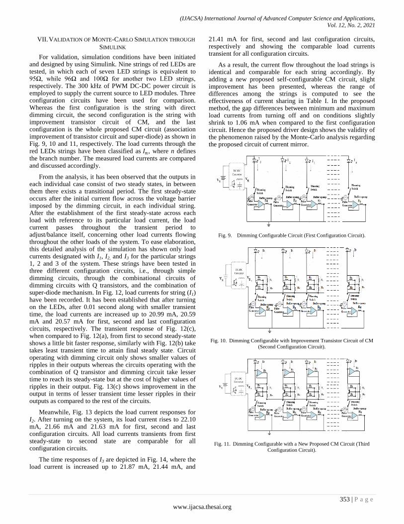
For validation, simulation conditions have been initiated and designed by using Simulink. Nine strings of red LEDs are tested, in which each of seven LED strings is equivalent to 95Ω, while 96Ω and 100Ω for another two LED strings, respectively. The 300 kHz of PWM DC-DC power circuit is employed to supply the current source to LED modules. Three configuration circuits have been used for comparison. Whereas the first configuration is the string with direct dimming circuit, the second configuration is the string with improvement transistor circuit of CM, and the last configuration is the whole proposed CM circuit (association improvement of transistor circuit and super-diode) as shown in Fig. 9, 10 and 11, respectively. The load currents through the red LEDs strings have been classified as , where n defines the branch number. The measured load currents are compared and discussed accordingly.
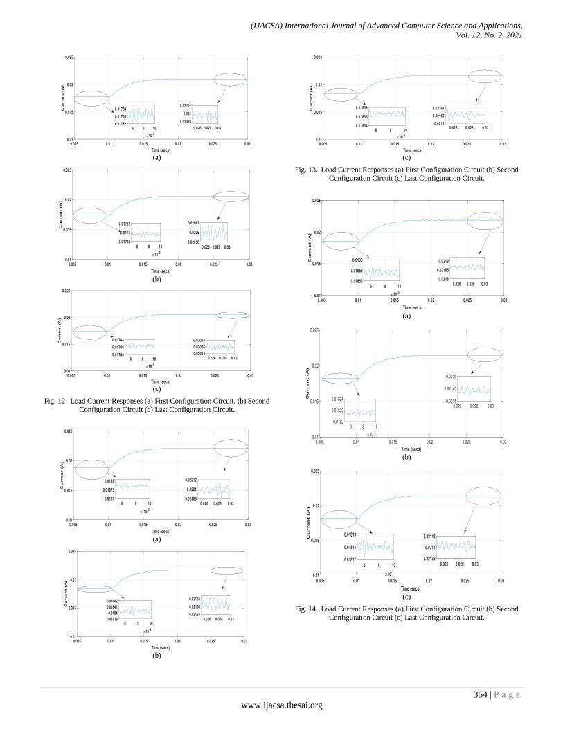
From the analysis, it has been observed that the outputs in each individual case consist of two steady states, in between them there exists a transitional period. The first steady-state occurs after the initial current flow across the voltage barrier imposed by the dimming circuit, in each individual string. After the establishment of the first steady-state across each load with reference to its particular load current, the load current passes throughout the transient period to adjust/balance itself, concerning other load currents flowing throughout the other loads of the system. To ease elaboration, this detailed analysis of the simulation has shown only load currents designated with I1, I2, and I3 for the particular strings 1, 2 and 3 of the system. These strings have been tested in three different configuration circuits, i.e., through simple dimming circuits, through the combinational circuits of dimming circuits with Q transistors, and the combination of super-diode mechanism. In Fig. 12, load currents for string (I1) have been recorded. It has been established that after turning on the LEDs, after 0.01 second along with smaller transient time, the load currents are increased up to 20.99 mA, 20.59 mA and 20.57 mA for first, second and last configuration circuits, respectively. The transient response of Fig. 12(c), when compared to Fig. 12(a), from first to second steady-state shows a little bit faster response, similarly with Fig. 12(b) take takes least transient time to attain final steady state. Circuit operating with dimming circuit only shows smaller values of ripples in their outputs whereas the circuits operating with the combination of Q transistor and dimming circuit take lesser time to reach its steady-state but at the cost of higher values of ripples in their output. Fig. 13(c) shows improvement in the output in terms of lesser transient time lesser ripples in their outputs as compared to the rest of the circuits.
Meanwhile, Fig. 13 depicts the load current responses for I2. After turning on the system, its load current rises to 22.10 mA, 21.66 mA and 21.63 mA for first, second and last configuration circuits. All load currents transients from first steady-state to second state are comparable for all configuration circuits.
The time responses of I3 are depicted in Fig. 14, where the load current is increased up to 21.87 mA, 21.44 mA, and
21.41 mA for first, second and last configuration circuits, respectively and showing the comparable load currents transient for all configuration circuits.
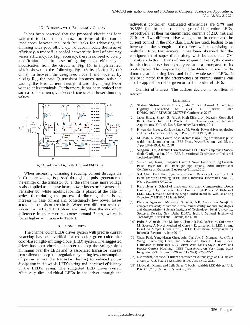
As a result, the current flow throughout the load strings is identical and comparable for each string accordingly. By adding a new proposed self-configurable CM circuit, slight improvement has been presented, whereas the range of differences among the strings is computed to see the effectiveness of current sharing in Table I. In the proposed method, the gap differences between minimum and maximum load currents from turning off and on conditions slightly shrink to 1.06 mA when compared to the first configuration circuit. Hence the proposed driver design shows the validity of the phenomenon raised by the Monte-Carlo analysis regarding the proposed circuit of current mirror.
Fig. 9. Dimming Configurable Circuit (First Configuration Circuit).
Fig. 10. Dimming Configurable with Improvement Transistor Circuit of CM
(Second Configuration Circuit).
Fig. 11. Dimming Configurable with a New Proposed CM Circuit (Third
Configuration Circuit).
(IJACSA) International Journal of Advanced Computer Science and Applications,
Vol. 12, No. 2, 2021
354 | P a g e
www.ijacsa.thesai.org
(a)
(b)
(c)
Fig. 12. Load Current Responses (a) First Configuration Circuit, (b) Second
Configuration Circuit (c) Last Configuration Circuit.
(a)
(b)
(c)
Fig. 13. Load Current Responses (a) First Configuration Circuit (b) Second
Configuration Circuit (c) Last Configuration Circuit.
(a)
(b)
(c)
Fig. 14. Load Current Responses (a) First Configuration Circuit (b) Second
Configuration Circuit (c) Last Configuration Circuit.
(IJACSA) International Journal of Advanced Computer Science and Applications,
Vol. 12, No. 2, 2021
355 | P a g e
www.ijacsa.thesai.org
TABLE I. COMPARISON OF THE RANGE DIFFERENCES OF LOAD
CURRENTS FOR I1, I2 AND I3
First configuration
circuit
Second configuration
circuit
Third configuration
circuit (a new
proposed self-
configurable CM
circuit)
I1=20.99 mA I1=20.59 mA I1=20.57 mA
I2=22.10 mA I2=21.66 mA I2=21.63 mA
I3=21.87 mA I3=21.44 mA I3=21.41 mA
Maximum current
difference =1.11 mA
Maximum current
difference =1.07 mA
Maximum current
difference =1.06 mA
Conventional current-mirror circuits need a buck converter to trade in with the one constant current load. The second topology to trade in with upgraded self-adjustable current-mirror methods that can address different LED loads under different conditions with the help of one buck converter. The working principle spin around an effective as well as self-configurable merged circuit of transistor and op-amp based current-balancing circuit, along with their dimming circuits. The suggested circuit assures uniformity at the circuit’s outputs. This particular scheme of current-balancing circuits excluded the requirement for distinct power supply to regulate the load currents through different kinds of LEDs, i.e., RGB LEDs. The proposed methods are identical and modular, going up to any number of connected corresponding current sources. The methodology has been proficiently examined in the environment of Simulink to substantiate the current balancing phenomenon in parallel LED strings.
VIII. EXPLORATORY ANALYSIS
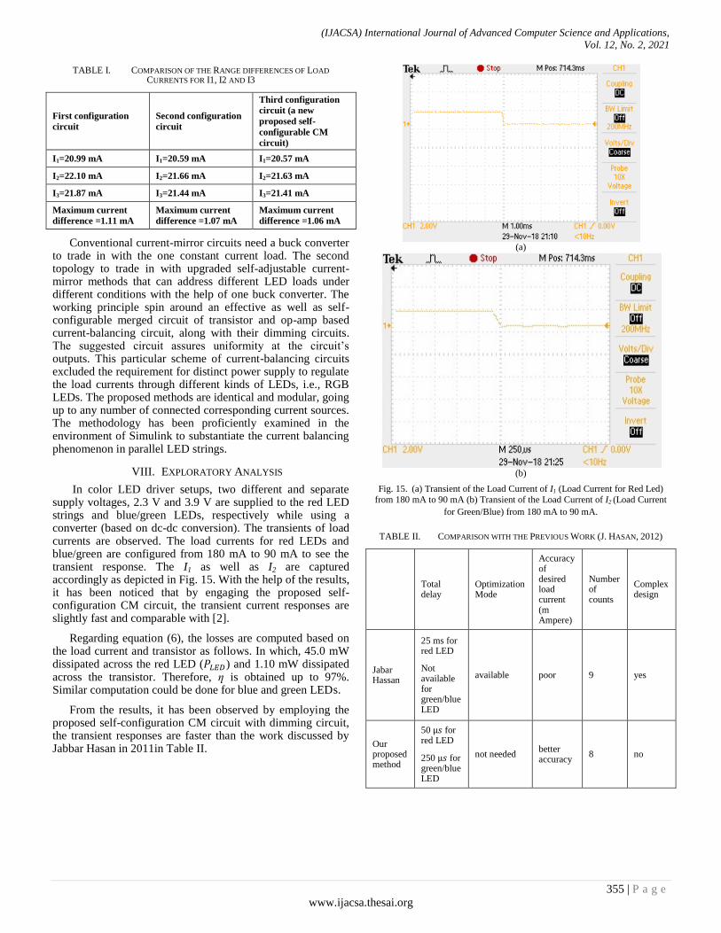
In color LED driver setups, two different and separate supply voltages, 2.3 V and 3.9 V are supplied to the red LED strings and blue/green LEDs, respectively while using a converter (based on dc-dc conversion). The transients of load currents are observed. The load currents for red LEDs and blue/green are configured from 180 mA to 90 mA to see the transient response. The I1 as well as I2 are captured accordingly as depicted in Fig. 15. With the help of the results, it has been noticed that by engaging the proposed self-configuration CM circuit, the transient current responses are slightly fast and comparable with [2].
Regarding equation (6), the losses are computed based on the load current and transistor as follows. In which, 45.0 mW dissipated across the red LED ( ) and 1.10 mW dissipated across the transistor. Therefore, ղ is obtained up to 97%. Similar computation could be done for blue and green LEDs.
From the results, it has been observed by employing the proposed self-configuration CM circuit with dimming circuit, the transient responses are faster than the work discussed by Jabbar Hasan in 2011in Table II.
(a)
(b)
Fig. 15. (a) Transient of the Load Current of I1 (Load Current for Red Led)
from 180 mA to 90 mA (b) Transient of the Load Current of I2 (Load Current
for Green/Blue) from 180 mA to 90 mA.
TABLE II. COMPARISON WITH THE PREVIOUS WORK (J. HASAN, 2012)
Total delay
Optimization Mode
Accuracy of desired load current (m Ampere)
Number of counts
Complex design
Jabar Hassan
25 ms for red LED
Not available for green/blue LED
available poor 9 yes
Our proposed method
50 for red LED
250 for green/blue LED
not needed better accuracy
8 no
(IJACSA) International Journal of Advanced Computer Science and Applications,
Vol. 12, No. 2, 2021
356 | P a g e
www.ijacsa.thesai.org
IX. DIMMING WITH EFFICIENCY OPTION
It has been observed that the proposed circuit has been validated to hold the minimization issue of the current imbalances between the loads but lacks for addressing the dimming with good efficiency. To accommodate the issue of efficiency, a tradeoff is needed between the level of accuracy versus efficiency, for high accuracy, there is no need to do any modification but in case of getting high efficiency a modification from the circuit in Fig. 16. is implemented, which shown in the following Fig. 16 by placing (10 ohms), in between the designated node 1 and node 2. By placing , the base Q transistor becomes more active in passing the load current through it and developing lesser voltage at its terminals. Furthermore, it has been noticed that such a combination gives 99% efficiencies at lower dimming values.
Fig. 16. Addition of in the Proposed CM Circuit.
When increasing dimming (reducing current through the load), more voltage is passed through the pulse generator to the emitter of the transistor but at the same time, more voltage is also applied to the base hence power losses occur across the transistor but while modification Ra is placed at the base in series, then during the process of dimming, there is no increase in base current and consequently low power losses across the transistor terminals. When two different resistive values i.e., 90 and 100 ohms are used, then the maximum difference in their currents comes around 2 mA, which is found higher as compare to Table I.
X. CONCLUSION
The channel color LEDs driver system with precise current balancing has been verified for red color–green color–blue color-based light-emitting-diode (LED) system. The suggested driver has been checked in order to keep the voltage drop minimum over the LEDs and its associated transistor (current controllers) to keep it in regulation by letting less consumption of power across the transistor, leading to reduced power dissipation in the whole LED’s string and increased efficiency in the LED’s string. The suggested LED driver system effectively dim individual LEDs in the driver through the
individual controller. Calculated efficiencies are 97% and 98.55% for the red color and green/ blue color LEDs, respectively, at their maximum rated currents of 21.0 mA and 22.0 mA. Two different drive voltages for the driver and the current control in the individual LEDs are used, leading to an increase in the strength of the driver which consisting of multiple LEDs. Furthermore, it has been observed that the configuration of super diode along with its associated CM circuits are better in terms of time response. Lastly, the counts in this circuit have been greatly reduced as compared to its predecessors. The proposed circuit facilitates the user to do dimming at the string level and in the whole set of LEDs. It has been noted that the effectiveness of current sharing can also be applied for red or green or for blue color of LEDs.
Conflict of interest: The authors declare no conflicts of interest.
REFERENCES
[1] Shaheer Shaheer Shaida Durrani, Abu Zaharin Ahmad: An efficient Digitally Controlled for RGB LED Driver, 2017 DOI:10.1109/ICETAS.2017.8277843 Conference: 2017.
[2] Jaber Hasan, Simon S. Ang:A High-Efficiency Digitally Controlled RGB Driver for LED Pixels” IEEE Transactions on Industry Applications, VoL. 47, No. 6, November/December, 2011.
[3] H. van der Broeck, G, Sauerlander, M. Vendt, Power driver topologies and control schemes for LEDs, in Proc. IEEE APEC, 2007.
[4] M. Doshi, R. Zane, Control of solid-state lamps using a multiphase pulse width modulation technique, IEEE Trans. Power Electron., vol. 25, no. 7, pp. 1894–1904, Jul. 2010.
[5] Sung-Jin Choi, Adaptive Current-Mirror LED Driver employing Super-diode Configuration, 2014 IEEE International Conference on Industrial Technology,2014.
[6] Yen-Chung Huang, Hung-Wei Chen: A Novel Fast-Switching Current-Pulse Driver for LED Backlight Applications” 2016 International Conference on Consumer Electronics-Taiwan,2016.
[7] S.-J. Choi, T.-H. Kim: Symmetric Current- Balancing Circuit for LED Backlight with Dimming, IEEE Trans. Industrial Electronics, Vol. 59, No. 4, pp.1698-1707,2012.
[8] Kang Hyun Yi School of Electronic and Electric Engineering, Daegu University “High Voltage, Low Current High-Power Multichannel LEDs LLC Driver by Stacking Single-Ended Rectifiers with Balancing Capacitors”, MDPI, 23 March 2020.
[9] Bhawna Aggarwal, Maneesha Gupta a, A.K. Gupta b a Netaji: A comparative study of various current mirror configurations: Topologies and characteristics, Subhash Institute of Technology, Delhi University, Sector-3, Dwarka, New Delhi 110078, India b National Institute of Technology, Kurukshetra, Haryana, India,2016.
[10] Pedro S. Almeida, Joao M. Jorge, Claudio R.B.S. Rodrigues, Guilherme M. Soares, A Novel Method of Current Equalization in LED Strings Based on Simple Linear Circuit, IEEE International Symposium on Industrial Electronics, June 201 I.
[11] Chen, Poki, Yung-Hsuan Chen, John Carl Joel S. Marquez, Ruei-Ting Wang, Jiann-Jong Chen, and Yuh-Shyan Hwang. "Low Flicker Dimmable Multichannel LED Driver With Matrix-Style DPWM and Precise Current Matching." IEEE Transactions on Very Large Scale Integration (VLSI) Systems 28, no. 11 (2020): 2233-2242.
[12] Nadershahi, Shahnad. "Current controller for output stage of LED driver circuitry." U.S. Patent 10,891,893, issued January 12, 2021.
[13] Modepalli, Kumar, and Leila Parsa. "N-color scalable LED driver." U.S. Patent 10,757,775, issued August 25, 2020.
Related Documents