Welcome message from author
This document is posted to help you gain knowledge. Please leave a comment to let me know what you think about it! Share it to your friends and learn new things together.
Transcript

An Automatic Registration Method for Frameless Stereotaxy, ImageGuided Surgery, and Enhanced Reality VisualizationW.E.L. Grimson1 G.J. Ettinger1;3 S.J. White3 T. Lozano-P�erez1W.M. Wells III1;2 R. Kikinis2February 22, 1996AbstractThere is a need for frameless guidance systems to help surgeons plan the exact location for incisions,to de�ne the margins of tumors and to precisely identify locations of neighboring critical structures. Wehave developed an automatic technique for registering clinical data, such as segmented MRI or CT recon-structions, with any view of the patient on the operating table, using a series of registration algorithms,which we demonstrate on the speci�c example of neurosurgery. The method enables a visual mix of livevideo of the patient with the segmented 3D MRI or CT model, supporting enhanced reality techniquesfor planning and guiding neurosurgical procedures, and to interactively view extracranial or intracranialstructures non-intrusively. Extensions of the method include image guided biopsies, focused therapeuticprocedures and clinical studies involving change detection over time sequences of images.1Arti�cial Intelligence Laboratory, Massachusetts Institute of Technology, Cambridge MA2Department of Radiology, Brigham and Womens Hospital, Harvard Medical School, Boston MA3The Analytic Sciences Corporation, Reading MA 0

1 Motivating ProblemMany surgical procedures require highly precise lo-calization on the part of the surgeon, in order toextract targeted tissue while minimizing damage toadjacent structures. The di�culty of this 3D lo-calization is exacerbated by the fact that it oftenrequires isolating a structure deeply buried withinthe body. While methods exist (e.g. MRI, CT)for imaging and displaying the 3D structure of thebody, the surgeon must still relate what she sees onthe 3D display with the patient's actual anatomy.As current methods often involve a surgeon sim-ply utilizing traditional two dimensional slices ofMRI or CT imagery and mentally transformingthat information to the actual patient, there is aclear need for registered visualization techniques, inwhich 3D reconstructions of internal anatomy areexactly overlaid with the surgeon's view of the pa-tient, so that she can directly visualize importantstructures, and plan and act accordingly.In this paper, we describe a method for executingthis automatic registration and visualization tech-nique. While this problem is particularly relevantin procedures that involve minimal invasion of thebody, such as biopsies, or endoscopic procedures,we use the problem of visualization and guidance inneurosurgical procedures as a motivating example.1.1 An Ideal SolutionIdeally, one would prefer a system that could auto-matically register 3D data sets, and track changes inthe position of a data set over time, without requir-ing the attachment of any devices to the patient.Such an ideal system should support:� real-time, adaptive, enhanced reality patientvisualizations in the operating room;� dynamic image-guided surgical planning;
� image guided surgical procedures, such as biop-sies or minimally invasive therapeutic proce-dures; and� registered transfer of a priori surgical plans tothe patient in the operating room.While our group is actively developing all aspectsof such a system, this paper focuses on one key com-ponent of such a system, the registration of di�erentdata sources to determine relevant coordinate frametransformations.1.2 Contributions to the Ideal SolutionWe have created a system that performs the regis-tration of clinical image data with the position ofthe patient on the operating table at the time ofsurgery, using methods from visual object recogni-tion. The method does not require the use of pre-viously attached frames or landmarks. The methodhas been combined with an enhanced reality visu-alization technique [14, 4, 41], in which we displaya composite image of the 3D anatomical structureswith a view of the patient. This registration en-ables the transfer to the operating room of preop-erative surgical plans, obtained through analysis ofthe segmented 3D preoperative data [8], where theycan be graphically overlaid onto video images of thepatient. Such transfer allows the surgeon to applycarefully considered surgical plans to the currentsituation, and to mark internal landmarks used toguide the progression of the surgery.Thus, the speci�c problem we consider is:� Input: a video view of the patient, togetherwith a segmented MRI or CT model of theanatomy of the patient, each de�ned in its owncoordinate system.� Output: a transformation aligning the modelwith the patient, and a transformation describ-1
ing the position and orientation of the videocamera relative to the patient.Extensions of our method include adaptively re-registering the video image of the patient to the 3Danatomical data, as the patient or the video sourcemoves, as well as other surgical applications such asimage guided biopsy, or focused therapeutic proce-dures (e.g. laser disc fusion or tumor ablation). Wehave also demonstrated the use of our system inclinical settings, by registering data sets acquiredover extended time periods, thereby enabling thedetection of changes in anatomy over time.2 An Example ScenarioThe following describes a scenario demonstratingthe use of our methods.(1) A patient requiring surgical therapy isscanned by a 3D, high resolution, internal anatomyscanner, such as Magnetic Resonance Imaging(MRI) or Computed Tomography (CT).(2) The current scan is segmented into di�erenttissue types, and graphical models of desired struc-tures (e.g. tumor, ventricles, skin surface, bone,white matter, etc.) are generated.(3) The patient is placed in the operating room,which is equipped with:� a laser range scanner for obtaining depth dataof the patient's skin surface where the surgeryis to be performed,� enhanced reality visualization equipment, suchas a video or digital camera, mixer and dis-play monitor; or a head-mounted display withtrackable landmarks,� the operating table may contain landmarksthat will remain viewable and �xed relative tothe patient during surgery,
� landmark tracking equipment.(4) Prior to draping, the patient is scanned bya laser range scanner. The 3D locations of any ta-ble landmarks are also calculated to identify theirlocation relative to the patient.(5) The current MRI or CT scan is automaticallyregistered to the patient skin surface depth dataobtained by the laser range scanner. This providesa transformation from MRI/CT to patient.(6) The position and orientation of a video cam-era relative to the patient is determined, by match-ing video images of the laser points on an object tothe actual 3D laser data. This provides a transfor-mation from patient to video camera.(7) The registered internal anatomy is displayedin enhanced reality visualization [14, 4, 41] to \see"inside the patient. In particular, the two previouslycomputed transformations can be used to transformthe 3D model into the same view as the video im-age of the patient, so that video mixing allows thesurgeon to see both images simultaneously.(8) The patient is draped and surgery is per-formed. The enhanced reality visualization does notinterfere with the surgeon, nor does it require herto do anything di�erent from that to which she isaccustomed. Rather, the system provides her withadditional visualization information to greatly ex-pand her limited �eld of view.(9) The location of table landmarks can be con-tinually tracked to identify changes in the positionof the patient's attitude, relative to the visualiza-tion camera. Visualization is maintained by updat-ing the MRI/CT to patient transformation.(10) Viewer location can be continually trackedto identify any changes in the position of theviewer. In the case of a stationary video camera,this is straightforward, though in the case of head-mounted displays such tracking is both more rele-vant and more challenging. Visualization updates2

are performed by updating the patient to viewertransformation.(11) In general, the surgical procedure is exe-cuted with an accurately registered enhanced visu-alization of the entire relevant anatomy of the pa-tient. The hope is that by providing this informa-tion to the surgeon, procedures can be more e�-ciently and e�ectively executed, with reduced sidee�ects to the patient.3 Details of Our ApproachPart 1 of this scenario is standard practice. Meth-ods currently exist for dealing with Part 2 [8, 13].Here we focus on parts 3{8 of the above scenario.Parts 9{11 are part of our planned future work. Forparts 3{8, the key step is the registration of data ob-tained from the patient in the operating room withpreviously obtained data and surgical plans.We use a multi-stage matching and veri�cation ofa 3D data set acquired at the time of the surgicalprocedure with 3D clinical data sets acquired pre-viously. The central ideas are to use a laser stripingdevice to obtain 3D data from the skin of the pa-tient at run time, and to use a sequence of recogni-tion techniques from computer vision to match thisdata to segmented skin data from the MRI or CTreconstruction. These matching techniques allow usto accurately register the clinical data with the cur-rent position of the patient. As a consequence wecan display a superimposed image of the 3D struc-tures overlaid on a view of the patient.The steps of our method are outlined below.3.1 Model inputWe obtain a segmented 3D reconstruction of the pa-tient's anatomy, for example using CT or MRI. Cur-rent segmentation techniques are generally semi-automatic. This process is typically done by train-
ing an intensity classi�er on a user selected set oftissue samples, where the operator uses knowledgeof anatomy to identify the tissue type. Once initialtraining is completed, the rest of the scans can beautomatically classi�ed on the basis of intensities inthe scanned images, and thus segmented into tissuetypes [8, 13]. Automatically removing gain artifactsfrom the sensor data can be used to improve thesegmentation [42]. Similarly, methods that correctfor distortions due to magnetic susceptibility di�er-ences between di�erent materials [35] can furtherimprove the accuracy of the segmentation.We refer to this 3D anatomical reconstruction asthe model, which is represented relative to a modelcoordinate frame. For simplicity, the coordinatesystem's origin is taken as the model centroid.3.2 Data inputTo achieve the registration, we �rst obtain a set of3D data points from the patient's skin surface usinga laser range scanner, which operates by scanninga laser beam through an optical mechanism thatresults in a controlled plane of light. A video cam-era is placed at an angle to this plane such that aportion of the plane is in the camera �eld of view.When an object is placed in this visible region suchthat it intersects the laser plane, points in the cam-era image illuminated by the laser unambiguouslycorrespond to �xed 3D scene points. The 3D mea-surements of the currently used scanner (TechnicalArts 100X) are accurate to within 0:08mm.We refer to this 3D information as the data,which is represented in a coordinate frame attachedto the laser, and which re ects the position of thepatient in a coordinate frame that exists in the op-erating room. Our problem is to determine a trans-formation that will map the model into the data ina consistent manner.3
3.3 Matching data setsWe �nd this transformation by matching the twodata sets using the following steps:(1) First, we separate laser data of the patient'shead from background data. Currently we do thiswith a simple user interface (Figure 1), in which theview from the laser's video camera is displayed withthe laser data overlaid on top of that view. The usercan use a simple mouse interface to block out laserpoints coming from the skin of the patient. Thislaser data can be further edited by displaying thedata, overlaid on the MRI model by means of therough transformation speci�ed above. Using anyof the three orthogonal views of the two data sets,the laser data can be furthered edited using a sim-ple set of mouse interfaces. Note that this processneed not be perfect, we simply want to remove grossoutliers from the data. There are also methods forextracting such data automatically.(2) To initiate the matching, we have several op-tions. First, we have developed a simple graphicalinterface (see Figure 1) that can be used to roughlyalign the laser data with the 3D model. The modelis displayed in its initial orientation on a series ofthree orthogonal 2D views, together with the laserdata. The user can re�ne the initial transformationby rotating and translating the data in any of thethree orthogonal views. This initial alignment doesnot need to be very accurate: rotational errors onthe order of 10{20 degrees, and translational errorson the order of centimeters are permissible, sincethe subsequent matching stage is quite reliable atremoving these misalignments.insert Figure 1 here(3) If we have a rough alignment provided by theuser, this is usually su�cient to move to the posere�nement stage described below. In some cases,however, we may not want to rely on user interven-tion (for example in the batch mode registration of
MRI scans acquired over time, described in a latersection). In this case, we need an automatic way ofe�ciently �nding good initial alignments. We havedeveloped several schemes for accomplishing this.If we do not want to rely on operator intervention,we can instead sample a set of evenly spaced direc-tions on the view sphere. For each view, we extracta sampled set of visible points of the model, usinga z-bu�er. In particular, given a pixel size for thez-bu�er and given an estimate for the view direc-tion, we project all of the model points into a planeorthogonal to the view direction, where the plane istesselated in pixels of the given side. Within eachpixel, we keep only the point closest to the viewer.This gives us a temporary model, which we can usefor matching. While it is possible in this method forpoints to leak through the z-bu�er from the backof the model, this does not a�ect the performanceof the method. This gives us a temporary model,which we can use for matching. The point on theview sphere serves to estimate the rotation neededto roughly align the model and the data. For eachsuch model and its associated alignment, we executethe matching process described below.Yet another method for removing the operatorintervention takes advantage of data itself to �ndinitial transformations. In particular, as a prepro-cessing step, we can hash all pairs of MRI pointsbased on distance between them. Furthermore, ateach MRI skin point, we can estimate the surfacenormal to the skin by a local �t of the neighbour-ing data. To �nd an initial transformation, we canselect any two laser data points, where for stabilityreasons we select two points that are widely sepa-rated. Using the distance between these two laserpoints, we can access the hash table to �nd pos-sible matching MRI points. For each such pair inthe hash table, if we consider the hypothesis thatthe laser points match the MRI points (there aretwo such matches), then this determine 5 of the 64

degrees of freedom associated with the coordinateframe transformation. The missing parameter is therotation about the axis connecting the two points.To solve for this parameter, we can estimate thenormal to the skin surface at the laser point by �t-ting a plane to the neighbouring data. Then therotation we need is the rotation about the axis be-tween the points that will rotate the laser normalto align with the MRI normal. Note that such a ro-tation may not exist, in which case we can discardthis pair. Similarly, after solving for the rotation,we can check that application of this rotation to thenormal at the other point also causes it to agreewith its matching normal. If not, the pair is dis-carded. By cycling over all the possible pairings ofMRI points to laser points, as de�ned by the entriesin the hash table, we can collect the set of feasibleinitial transformations. These can be ranked on thebasis of the RMS �t of the transformed laser datato the MRI data, and the resulting rank orderedlist of hypotheses can be further processed usingthe methods described below, stopping when a suf-�ciently accurate �t is found.A related approach is to use Interpretation TreeSearch [16, 17, 15] to match triples of visible sam-pled model points to the three selected laser points.This method basically searches over all possibleways of matching three laser points (selected to bewidely separated from one another) to three pointsselected from the sample MRI model. For each pair-ing of triples of model and data points, the methodtests whether the pairwise distances between modelpoints and laser points are roughly the same. Ifall such tests are valid, the match is kept, and wecompute the coordinate frame transformation thatmaps the three laser points into their correspond-ing model points. These transformations form aset of hypotheses. Note that due to the samplingof the model data, the actual object points corre-sponding to the selected laser points may not exist,
so these hypothesized transformations are at bestapproximations to the actual transformation. Fore�ciency, we hash pairs of points on distance, andonly retrieve likely candidates for testing.In the example shown in Figure 2, there are 481laser sample points, and the skull model has 35,265sample points. Given an initial sampled viewpointand a coarsely sampled z-bu�er, there are 409modelpoints in the sampled view. In principle, there are 4813 ! 4093 ! � 2:02e14possible hypotheses for the aligning transformation,but using simple distance constraints (and allowingfor some amount of error in the distance measure-ments), there are only 16,945 possible hypothesesthat remain for further testing.(4) We can use the Alignment Method [22] to�lter these hypotheses. In particular, we �lter outthose hypotheses for which the transformed viewvector becomes unviewable (e.g. lies below the op-erating table). Then, for each remaining hypothe-sis, we transform all the laser points by the hypothe-sized transformation, and verify that the fraction ofthe transformed laser points that do not have a cor-responding model point within some prede�ned dis-tance is less than some prede�ned bound. We dis-card those hypotheses that do not satisfy this veri�-cation. For e�ciency, we use two levels of samplingof the laser points, �rst verifying that a coarselysampled set of laser points are in agreement, thenfurther verifying, for those that pass this test, thatall the laser points are in agreement.An example of the two data sets (model and laserdata) after a veri�ed alignment is shown in Figure2. For this example, there is only one surviving hy-pothesis, out of the 16,945 initial hypotheses. Notethat some of the laser points are partially buried inthe CT model (displayed as partially transparent),indicating that the initial alignment is close but notsu�ciently accurate.5
(5) For each veri�ed hypothesis (whether ob-tained automatically or by initial user alignment),we re�ne the alignment of the two data sets by min-imizing an evaluation function that measures theamount of mismatch between the two data sets.(5.1) Evaluate the current pose by summing, forall transformed laser points, a term that is itself asum of the distances (weighted by a Gaussian dis-tribution) from the transformed point to all nearbymodel points [40]. This Gaussian weighted distribu-tion is a method for roughly interpolating betweenthe sampled model points to estimate the nearestpoint on the underlying surface to the transformedlaser point. More precisely, if `i is a vector repre-senting a laser point, mj is a vector representing amodel point, and T is a coordinate frame transfor-mation, then the evaluation function for a particu-lar pose (or transformation) isE1(T ) = �Xi Xj e� jT `i�mj j22�2 : (1)This objective function is similar to the posteriormarginal pose estimation (PMPE) method used in[40], and to the elastic net constraints of [9]. Onecan visualize this objective function as if we placeda Gaussian distribution of some spread � at eachmodel point, then summed the contributions fromeach such distribution at each point in the vol-ume. Then the contribution of each transformedlaser point towards the evaluation function is sim-ply the summed value at that point. Because ofits formulation, the objective function is generallyquite smooth, and thus facilitates \pulling in" solu-tions from moderately removed locations in param-eter space. As well, it bears some similarity to theradial basis approximation schemes used for learn-ing and recognition (e.g. [5, 10]).(5.2) In earlier versions of the system, we usedPowell's method [34] to iteratively minimize thisevaluation function. Powell's method is basically
a conjugate gradient descent method. Starting atsome initial point, it searches along a line in theparameter space for the point that minimizes theobjective function along that line. Then from thatpoint it picks a new direction and mimizes alongthat line, and so on. Ideally, such methods shouldpick \conjugate" directions along which to min-imize, that is, directions with the property thatmovement along a new such direction will not spoilthe minimization along previously used directions.Powell's method is a simple means for choosingthese conjugate directions, without directly esti-mating the gradient of the objective function.It is more e�cient, however, to use the Davidon-Fletcher-Powell quasi-Newton method [34]. This re-quires an estimate of the gradient of the objectivefunction, which we describe below. To estimate thegradient of the object function, we need the par-tial derivatives of that function with respect to thetransformation parameters p, this is given by@E1@p =Xi Xj �1�2 e� jT `i�mj j22�2 �T `i �mj ; @T `i@p � ;(2)where h�; �i denotes a dot product. For each of thetranslation components of the transformation, thepartial derivative is straightforward, for example:@T `i@tx = uxwhere tx is the x component of the translation vec-tor, and ux is a unit vector in the x direction. Theother two translation components are similar.For the rotation components, we can treat the ro-tation as an instantaneous rotation about three or-thogonal axes. For each axis r with associated angleof rotation �, applying Rodrigues' formula su�cesto show that the partial derivative is given by thefollowing cross product:@T `i@� = r � R`i6

where R is the associated rotation matrix. Thus thegradient of the evaluation function is straightfor-wardly computed using the appropriate expressionsfor the partial derivatives in equation (2).The DFP method essentially iteratively builds upa good approximation to the inverse Hessian ma-trix, which can then be applied to the data to solvefor the parameters yielding a minimum of evalua-tion function [34]. Solving this minimization prob-lem yields an estimate for the pose of the laserpoints in model coordinates.(5.3) Execute this re�nement and evaluation pro-cess using a multiresolution set of Gaussians. Thusinitially a broad based Gaussian is used to allowin uence over large areas, resulting in a coarse ini-tial alignment, but one which can be reached froma wide range of starting positions. Subsequently,more narrowly tuned Gaussian distributions can beused to re�ne the pose, while focussing on onlynearby model points to derive the pose.(5.4) Using the resulting pose of this re�nement,repeat the pose evaluation process, now using a rec-ti�ed least squares distance measure. In particular,perform a second sampling of the model from thecurrent viewpoint, using a much more �nely sam-pled z-bu�er. Relative to this �ner model, evalu-ate each pose by measuring the distance from eachtransformed laser point to the nearest model point,(with a cuto� at some prede�ned maximum dis-tance). Evaluate the pose by summing the squareddistances of each point. Minimize using the DFPmethod to �nd the least-squares pose solution. Herethe evaluation function isE2(T ) = " 1nXi min�d2max;minj jT `i �mj j2�# 12(3)where dmax is some preset maximum distance, andwhere n is the number of laser points `i. This ob-jective function is essentially the same as the maxi-mum a posteriori model matching scheme of [40]. It
acts much like a robust chamfer matching scheme,or an iterative closest point matching scheme, sim-ilar to that used by [23, 28, 3]. To use DFP on thisevaluation function, we again need to estimate thegradient, which is given by:@E2@p = 1n h 1n Pimin �d2max;minj jT `i �mj j2i�12 ��Pi DT `i �mj ; @T `i@p E ; (4)where we assume that for small changes, the closestpoint does not change, and hence the min operationcan be ignored. The partial derivatives in this caseare identical to those used in the previous case.The expectation is that this second objectivefunction is more accurate locally, since it is com-posed of saturated quadratic forms, but it is alsoprone to getting stuck in local minima. Hence weadd one more stage.(5.5) We observe that while the above methodalways gets very close to the best solution, it canget trapped into local minima in the minimizationof E2. To improve upon this, we take the pose re-turned by the above step, and perturb it randomly,then repeat the minimization. We continue to dothis, keeping the new pose if its associated RMS er-ror is better than our current best. We terminatethis process when the number of such trials thathave passed since the RMS value was last improvedbecomes larger than some threshold.(5.6) The best found solution is a pose, and ameasure of the residual deviation of the �t to themodel surface. An example is shown in Figure 2.(5.7) An alternative to using all of the laser datais to instead utilize laser data that is \more distinc-tive". We do this by estimating the curvature, alongthe plane of the laser, at each laser data point, andkeeping only a prede�ned percentage of the mosthighly curved laser points. The motivation is to re-strict our matching to points that carry more infor-mation about the local structure of the surface. Ini-7

tial experiments show that using only highly curvedpoints improves the residual RMS error.(5.8) Once the �nal solution is found, the resid-ual error at each point can be measured, and laserpoints with large residual errors can be removedfrom the data set. This automatically deletes pos-sible outliers. The �nal stages of the registrationprocess can then be rerun using the remaining data,to obtain a tighter �t to the surface.insert Figure 2 hereWe collect such solutions for each veri�ed hypoth-esis, over all legal view samples, and rank orderthem by smallest RMS measure. The result is ahighly accurate transformation of the MRI data intothe coordinate frame of the laser sensor.3.4 Camera CalibrationGiven a registration, we need to relate it to a viewof the patient. A video camera can be positionedin roughly the viewpoint of the surgeon, i.e. look-ing over her shoulder. By calibrating the positionand orientation of this camera relative to the lasercoordinate system, we can render the aligned MRIor CT data relative to the camera's view. This ren-dering can be mixed with the live video signal, giv-ing the surgeon an enhanced reality view of the pa-tient's anatomy [14, 4, 41]. This can be used to plana craniotomy or a biopsy, or to de�ne the marginsof an exposed tumor for minimal excision.When the laser scanner video camera is used forthis purpose, the solution for the camera model isstraightforward. Points in the laser scan of any ob-ject in the camera �eld have unique correspondenceswith points in the image plane. During calibra-tion, scan points from a calibration object are usedto generate an approximation of the camera pose.When a patient is scanned, corresponding 3D lasermeasurements and image points from the skin areused to re�ne the camera pose model via Powell's
method.When an independent camera is used for videocapture from the surgeon's view a similar methodis used using objects in the scene with at surfacefacets. Images of the laser slices are taken withthe video camera. Straight 2D line segments arelocated in the video images and matched to cor-responding straight 3D line segments in the laserdata. If three such matching segments are found,they can be used to solve for an approximation tothe perspective projection transformation, and thusfor the pose of the camera. Using this as a start-ing point, Powell's method can again be used tooptimize the pose estimate to best bring all of thelaser line segment data into projective alignmentwith the corresponding video data. Thus, one canuse simple faceted objects in the surgical setting di-rectly to calibrate the camera, and this process canbe repeated throughout the surgical procedure asneeded (e.g. if the position of the camera relative tothe operating table is perturbed).If a small number of �ducial points are known inboth laser coordinates and image coordinates, thenmethods exist for automatically solving or updatingthe camera calibration parameters (e.g. [29]).Figure 3 shows the alignment of the CT modelof the skull with the actual image of the skull in acalibrated video camera, demonstrating the type ofvisual overlay provided by this system.insert Figure 3 here3.5 VisualizationWe can combine the camera calibration and the reg-istration of the data sets, to achieve a visualizationof the data. In particular, we can apply the trans-formation between the data sets to bring the MRIor CT model into alignment with the patient, inthe coordinate frame of the laser system. We canthen project that model into the coordinate frame of8

the video camera, by applying the computed cam-era model. This gives us a virtual view of the MRImodel, as seen by that camera. This can then bemixed with an actual video view of the camera, andused as a visualization tool by the surgeon.4 Testing and Application of theMethodAs a �rst test, we have run a series of controlled ex-periments, in which we have registered a CT recon-struction of a plastic skull with laser data extractedfor a variety of viewpoints. We have run the sys-tem both with an initial estimate of body and noseaxes, and where we sample over a range of views onthe viewing sphere. In all cases, the system �ndsa \correct" registration, with typical residual RMSerrors of 1.6 millimeters. The issue of how reliableRMS error is as a measure of success is discussed inthe next section. Examples are shown in Figure 4.For example, using the skull data of Figure 2, andsampling over a set of views, leads to the statisticsshown in Table 1.Insert Figure 4 hereInsert Table 1 hereAs a second test, we have run trials matchinglaser data against an MRI scan of one of the au-thors, an example of which is shown in Figures 5and 6. Figure 5 shows the result of registering laserdata against the MRI skin surface. Figure 6 is avisualization in which the surface of the brain hasbeen rendered and registered with the view of thepatient, and the result projected and mixed with avideo image of the patient. We have run the sys-tem both with an initial pose estimate, and by sam-pling a range of views on the viewing sphere. In allcases, the system �nds a correct registration (Fig-ure 6), with typical residual RMS errors on the or-der of 1:5mms. The resolution of this MRI scan is
0:9375� 0:9375� 1:5mms.insert Figure 5 hereinsert Figure 6 hereWe have also run a series of trials with neuro-surgery patients. An example registration of thelaser data against MRI models of a patient is shownin Figure 7. The tumor and the ventricles of the pa-tient are highlighted. The RMS errors in such caseswere typically about 1:5mms.insert Figure 7 hereWe have been using this registration and visual-ization method to transfer presurgical plans to thepatient. In our current method, we use our regis-tration method to provide a visual overlay of theview of the patient with internal structures selectedby the surgeon. By viewing this overlay on a livevideo monitor, the surgeon can trace with a markerthe outline of key structure on the patient's scalp[14]. This enables the surgeon to mark locationsfor planned surgical steps, prior to the placementof the patient in the OR. To date, we have usedthis procedure on roughly 20 neurosurgical patientsat Brigham and Women's Hospital in Boston, MA.(See Section 6.)Besides applications for surgical planning andguidance, the method has other applications, in-cluding the registration of multiple clinical data setssuch as MRI versus CT. As a demonstration of this,we have registered sequences of MRI scans of thesame patient, taken over a period of several months,and used di�erences in the registered scans to visu-alize and measure changes in anatomy [11]. Thesescans were part of a NIH study of multiple sclerosis(MS) at Brigham and Women's Hospital aimed atdetermining the optimal frequency for performingMR imaging of MS patients. In this testing, we au-tomatically registered 20 sets of 50 MRI scans each.9

5 Computational EvaluationWe have examined a series of issues relating to thecomputational performance of our system. The re-sults of our testing are described in this section.5.1 Minimization errorIt is worth commenting on the interpretation of theRMS error. First, the issue of what is a correctregistration is somewhat di�cult to evaluate on thebasis of RMS error. Certainly solutions with lowRMS are likely to be good �ts of the two data sets,by de�nition, but this does not ensure that they are\correct". Rather, RMS is a measure of the \suc-cess" of the method at �nding a good �t betweendata sets, while the correct registration is one inwhich homologous anatomical points are mappedonto one another. To test this latter issue, we needto perform phantom studies of some sort, an issuewe are currently investigating.Second, we are actually mostly interested in howaccurately we have measured the transformation.While the RMS measure is a useful indicator of �t,the actual transformation, when applied to modelpoints, may be much more accurate. This is dis-cussed later in this section.Third, the RMS error will clearly be a func-tion of the density of the model points. For e�-ciency, we often run the method with a subsam-pling of the MRI model. To explore the e�ect ofthis sampling on the residual error, we ran experi-ments on two patients, in which we varied the sam-pling of the MRI and recorded the �nal RMS error.This is graphed in Figure 8. One can see that asmore model points are included the RMS error de-clines to roughly 1 mm. Note that the voxel sizeis 0:9375� 0:9375� 1:5mms so that the expectedRMS error just due to the discrete size of the voxelsis :578mm. When combined with the fact that weare measuring distance to the nearest vertex of an
isosurface triangle, not to the actual surface itself,one can see that the method is close to the limit ofRMS accuracy. The key issue here is how to strikea good balance between the e�ciency one gains byusing a sample of the full MRI model and the po-tential cost in goodness of �t introduced by such asampling. Figure 8 that sampling rates of 2 or 3probably introduce very little error, while samplingrates of 5 are probably the limit one should tolerate.One way of dealing with the fact that the MRIdata points are only a sampling of the surface isto attempt to account for residual errors in model-ing the surface. In particular, when evaluating theterms in equation 3, one still searches for the closestMRI point to the transformed laser point. Ratherthan summing jT `i �mj j2over all such points, we use the normal componentj (T `i �mj) �Nj j2where Nj is the normal to the surface at the pointmj . Thus, we use the component of the distancevector between the transformed laser point and thenearest MRI point, in the direction of the normal tothe MRI surface at that point, rather than simplyusing the distance of the vector itself. This willreduce the e�ects of errors due to subsampling theMRI surface. We will return to this point in thetesting described below.Finally, it is worth noting that the sparsity of thelaser data clearly impacts on the RMS error. If thelaser data were dense, so that we could be guaran-teed of getting data from portions of the skin withvarying structure, it is likely that the RMS errorwould be signi�cantly reduced. Our experience inmatching MRI scans to MRI scans using this tech-nique supports that observation. We stress, how-ever, that the RMS error is probably less relevantto determining accuracy of the method than the is-sue of repeatability discussed below.10

insert Figure 8 here5.2 RepeatabilityA key issue with any registration algorithm basedon minimizing an evaluation function is the ques-tion of local minima. Since most realistic objectivefunctions will have complex associated energy land-scapes, it is important to test that the algorithmavoids getting trapped in local minima, and insteadis reliable at �nding the best global minimum.To explore this issue, we ran the following test.We took several cases involving real patients, andfound a transformation close to what appears to bethe correct alignment. We then ran a series of tri-als in which we perturbed that transformation andused the result as an initial alignment to the reg-istration algorithm. We then let the registrationmethod converge to a solution, which we recorded.In typical trials, we perturbed the transformationby n millimeters of translational o�set, and 2n de-grees of rotational o�set. We have run trials wheren ranged from 1 to 10, with the method successfully�nding correct solutions. A detailed example of aset of trials is given in Table 2, using a perturbationof 5 mms and 10 degrees, and using a sampling ofone in every 5 MRI points. One can see that factor-ing out the normal component of the residual errorreduces the overall RMS error, and that typicallythe RMS error is on the order of the size of a voxel.Insert Table 2 hereMore importantly, to test the repeatability of thesystem in �nding the same transformation, we tookeach cluster of transformations and applied the fol-lowing test. We computed an entry vector into theskull, based on the surgeon's expected trajectory.We then applied each transformation out of theclustered set to that vector, collecting a set of pos-sible entries. Starting at the skin surface, we traceda set of points along each of the transformed entry
vectors, for example using a vector 6 centimeterslong and sampling every centimeter along the ray.This de�nes a cluster of points at each sampling,based on the deviation in the computed transfor-mations applied to the expected entry vector. Thekey question is how much spread there is in thesepoints, since that will determine the deviation thatthe surgeon might be expected to see from the ideallocation. To measure this, we found the centroid ofeach cluster of points, then computed statistics onthose clusters, which are described in in Table 3. Weran tests in which the normal component of resid-ual error was used and in which the full residualerror was used. As well, we varied the thresholdon RMS error below which a solution was accepted.As one might expect, while this may occassionallycause the system to miss a solution (as shown bythe success rate) it does reduces the deviation inthe computed entry vectors.Insert Table 3 hereIt is worth noting the range of variation in theresults. In particular, in the case of the skull andPatient 070194, the laser data primarily covered theface, where there is considerable variation in struc-ture. This led to very low deviations in entry vector,because the structure served to distinctively iden-tify the best registration. The remaining variation(on the order of 10-30 microns) is probably mostlydue to the fact that we are randomly sampling ev-ery �fth point in the MRI skin surface, which canintroduce a small amount of residual perturbation.In the case of Patient 071594 and Patient 082294,the laser data primarily covered the cheek and sideof the face (other cases we have run cover the backor the top of the head), where there is much lessdistinctive data available. In these cases, the resid-ual deviation is higher. In one case, where some ofthe laser data came from the nose of the patient,the typical deviation was 100 microns. In the sec-ond case, the laser data was almost entirely from11

the check of the patient, and here the typical de-viation was on the order of 1.6 millimeters. In allcases, one can see from the 95 percentile statisticsthat extreme deviations are very rare.One conclusion from this data is that a good wayto utilize the system is to ensure that the laser sys-tem acquires data from the face if the patient, en-sure reliable registration, then using the visualiza-tion camera in whatever orientation is best suitedfor the surgeon.Finally, we note that while using normal residualerror reduces the RMS error associated with solu-tions, it does not improve the reliability of the sys-tem to �nd the same solution.5.3 Capture RadiusAnother way of testing the method is to run a cap-ture radius test. In this trial, we took the datafrom one of our patients, and found a good regis-tration for that patient's data. With that as a start-ing point, we randomly perturbed the solution by atranslational o�set of n mms and a rotational o�setby 2n degrees (note that the rotational e�ects willresult in an overall translation of data by more thannmms). For each value of n we ran 20 trials, gath-ered the resulting transformations and performed acluster analysis similar to the cases above. Table 4and 5 summarize the results. Note that during thesetrials we set dmax to 10 mms so that we rely on theGaussian based minimization E1 doing a good jobof pulling the registration into close range. In Table4 and 5 we list two sets of results, one where we keepall legal transformations as part of our cluster, andone where we restrict ourselves to transformationswith good RMS values. The latter case increasesthe number of trials with no solution, but improvesthe accuracy of the found solutions. The observa-tion is that a capture radius of 5mms and 10degressis very reliable, and can easily be obtained auto-
matically by our indexing method, or can easily beobtained by our simple user interface. If we are will-ing to take more than one trial, should the �rst trialresult in an unacceptable registration, as measuredby the RMS error, then the capture radius easilyextends to twice this range.Insert Table 4 hereInsert Table 5 here6 Clinical TestingWe have tested our system on a number of actualneurosurgery patients1 at Brigham and Women'sHospital for the purpose of accurately planningcraniotomy locations. Each patient had a MRI scanperformed approximately one day prior to surgery.Clinicians at the Surgical Planning Lab segmentedthe MRI scan into skin, brain, tumor, ventricles,and other structures of interest. Once the patient'shead was shaved in preparation for surgery he wasbrought to the Surgical Planning Lab for laser reg-istration by our system. The registration procedureconsisted of the following steps:(1) Place the laser scanner over the patient'shead such that the camera is positioned at the ex-pected angle of approach to the tumor.(2) Scan the patient's head with the laser.(3) Edit the laser data, as overlaid on the videoimage of the patient, by roughly outlining the regionof interest, namely the patient's head.(4) Coarsely align the laser data with the seg-mented MRI skin model, using re�nements throughinteractive mouse rotation and translation of thelaser data overlaid on the MRI model.(5) Execute the automated registration startingwith the coarse initial alignment.(6) Verify the registration by a visual animationof the transformed MRI skin overlaid on the video1Twelve patients tested as of April, 1995.12

image as well as a color coded examination of resid-ual errors of transformed laser data overlaid on theMRI skin model.(7) Render the internal brain structures in theirregistered locations relative to the camera, suchthat they can be mixed with the video signal toproduce an enhanced reality visualization.(8) The surgeon draws the position of the tumorand other structures of interest directly on the scalpwhile looking at the visualization. The selectionand opacity of the di�erent anatomical structures isdynamically controlled to provide the surgeon withas much geometric information as possible from thegiven viewpoint.Each of the steps in the process can be repeatedto re�ne the surgical plan. Elapsed time for steps2 through 6 is approximately �ve minutes. Previ-ously performed manual alignment aimed at achiev-ing such visualizations could take as much as 45minutes with an accuracy of 10-30 mms. Our reg-istration thus achieves an order of magnitude im-provement in both e�ciency and accuracy, two fac-tors which are critical to the neurosurgeons. Feed-back from the surgeons has been highly positive asthey have found this easily accessible form of 3Dgeometric knowledge to prepare them well for thesurgeries. Current work involves migrating the useof the laser registration system into the OR for neu-rosurgery guidance as well as for planning and guid-ing other types of surgery.7 Other ApplicationsAs mentioned earlier, the method has applicationsfor surgical planning and guidance, including tu-mor excision and biopsy. The method has broaderapplication, however, including the registration ofmultiple clinical data sets such as MRI versus CT.As a demonstration of this, we have taken two MRIscans of the same patient, obtained several months
apart. These scans are part of an ongoing NIHstudy of multiple sclerosis (MS) at Brigham andWomens Hospital aimed at determining the opti-mal frequency for performing MR imaging of MSpatients. Under this study patients with varyingdisease stages are imaged at di�erent frequencies toidentify changes in MS lesion activity. To supportthis analysis, one needs to register the MRI scansfrom di�erent points in time, and compare them todetect relevant changes. We have applied our tech-nique to this task, using the surface of the intra-cranial cavity (ICC) as the basis for the registration.An original MRI ICC surface is used as a model, anda second MRI ICC surface is aligned with the �rstby sampling points on that surface (taking 1 out ofevery 30 points at random). Two views of the re-sulting overlay are shown in Figure 9. The resolu-tion of these scans is 0:9375mm�0:9375mm�3mm.insert Figure 9 hereGiven this alignment, we can transform the sec-ond data set into the coordinate frame of the �rstdata set, then resection the data to obtain 2D slicesequivalent to those of the �rst data set (with aninterpolation to estimate the values in the resec-tioned slices). Given these new sections, we canthen compare individual slices of the �rst data setto the resectioned second data set, and do imagedi�erencing to �nd noticeable changes. An exam-ple of this, highlighting the growth of a lesion in thepatient is shown in Figure 10.insert Figure 10 here8 Related WorkRegistration of data sets is an important problemin many medical applications, and hence has seenconsiderable work in the past. Two recent reviewsof registration methods include [39, 1]. Of particu-lar relevance are three di�erent approaches. First,Pelizzari and colleagues [31, 27, 26, 18, 38, 33, 32,13

30] have developed a method that matches retro-spective data sets, such as MRI or CT or PET, toone another. Similar to our approach, this workuses a least squares minimization of distances be-tween data sets, although their system uses a dif-ferent distance function for minimization, in partic-ular using for each data point, the distance fromthat data point to the model surface, as measuredalong a ray from the data point to the centroid ofthe model. Typical reported RMS errors are onthe order of 3-5mms. As opposed to our system,however, this approach does require some operatorintervention to set a decent initial starting position,which our system does not. It also apparently re-quires some operator intervention to steer the sys-tem towards the correct solution, suggesting thatlocal minima are a potential problem. Our systemavoids this di�culty by randomly perturbing near�nal solutions to �nd better nearby minima.A second related approach is that of [6, 7, 24, 25,36]. This method also does a least-squares mini-mization of a distance function to match data sets.Here, the distance is weighted by an estimate ofthe inverse variance of the noise in the measure-ments, and a Levenberg-Marquardt method is usedto �nd the minimum. It appears that at present themethod requires a reasonable initial starting posi-tion, though the authors observe that sampling overthe view sphere could remove this restriction. Oncea �rst estimate of the solution is found, points withlarge errors are removed (they are considered to beoutliers) and the minimization process is repeatedto re�ne the pose. It is unclear whether the removalof outliers is su�cient to keep the method from get-ting trapped into local minima.A third approach is that of [2, 19, 20, 21, 12, 37]who perform automatic rigid registration of 3D sur-faces by matching ridge lines which track points ofmaximum curvature along the surface. The ridgelines are characterized by �ve intrinsic parameters
(curvature, torsion, maximum curvature of the sur-face, angle between curve and surface normal, andangle between curve tangent and direction of max-imum curvature) which are used to hash the ridgepoints of the model data set into a �ve-dimensionalhash table. During matching, the hash table is usedto e�ciently �nd model ridge points which are sim-ilar to ridge points from a second data set. A rigidtransform is computed for each pair of matchedridge points and the results are collected in a six-dimensional transform accumulator. The most ac-cessed cell in the accumulator is selected as the besttransform. This method is not directly suitable fordealing with sparse data, such as the laser input.9 ConclusionsWe have described a method that automaticallyregisters segmented clinical reconstructions (suchas MRI or CT) of a patient with a live view ofthat patient, enabling a surgeon to visualize inter-nal structures before executing procedures. Themethod enables a visual mix of live video of thepatient with the segmented 3D MRI or CT model,supporting enhanced reality techniques for planningand guiding neurosurgical procedures, and to inter-actively view extracranial or intracranial structuresnon-intrusively. Extensions of the method includeimage guided biopsies, focused therapeutic proce-dures and clinical studies involving change detec-tion over time sequences of images. The methodhas been applied to a series of neurosurgery cases,and has demonstrated reliability in accurately lo-cating internal structures.The heart of the method is a multi-stage, multi-resolution, registration method that can be used infully automatic or semi-automatic mode, and whichreliably �nds solutions whose accuracy at �nding atarget ranges from 10 microns, in cases where highlyvaried structures are sensed, to 1:5 millimeters, in14

cases where much smoother structures are sensed.These results suggest that the best use of this vi-sualization technique is to register based on datataken from a highly structured viewpoint, such asthe face of a neurosurgery patient, but to use a vi-sualization viewpoint from whatever view is desiredby the surgeon.References[1] Ayache, N., \Medical Computer Vision, Virtual Re-ality and Robotics" Image and Vision Computing,13(4):295{313, May 1995.[2] Ayache, N., J.D. Boissonnat, L. Cohen, B. Geiger, J.Levy-Vehel, O. Monga, P. Sander, \Steps Toward theAutomatic Interpretation of 3-D Images", In 3D Imag-ing in Medicine, edited by H. Fuchs, K. Hohne, S. PizerNATO ASI Series, Springer-Verlag, 1990, pp 107-120.[3] Besl, J.P., N.D. McKay, \A method for registration of3D shapes", IEEE Trans PAMI 14:239{256, 1992.[4] Black, P. McL., R. Kikinis, W. Wells, D. Altobelli, W.Lorensen, H. Cline and F. Jolesz, \A New Virtual Re-ality Technique for Tumor Localization" Program Bookof the Annual Meeting of the Congress of NeurologicalSurgeons, 1993.[5] Brunelli,R and T. Poggio, 1991, \HyberBF Networksfor Real Object Recognition", Int. Joint Conf. Artif.Intell., Sydney, Australia.[6] Champleboux, G.; Lavallee, S.; Szeliski, R.; Brunie,L., \From accurate range imaging sensor calibrationto accurate model-based 3D object localization", IEEEConf. CVPR:83{89, 1992[7] Champleboux, G.; Lavallee, S.; Sautot, P.; Cinquin,P., \Accurate calibration of cameras and range imag-ing sensor: the NPBS method", IEEE Int. Conf. Rob.Autom.:1552{1557, 1992[8] Cline, H.E. and W.E. Lorensen and R. Kikinis and F.Jolesz, 1990, \Three-Dimensional Segmentation of MRImages of the Head Using Probability and Connectiv-ity." JCAT 14(6):1037-1045.[9] Durbin, R., R. Szeliski, and A. Yuille, \An analysisof the elastic net approach to the travelling salesmanproblem," Neural Computation 1(3):348{358, Fall 1989.
[10] Edelman, S. and T. Poggio, 1992 \Bringing the grand-mother back into the picture: a memory-based view ofobject recognition", Intl. J. Pattern Recog. Artif. Intell.6:37{61.[11] Ettinger, G., E. Grimson, T. Lozano-Perez, W. Wells,S. White, R. Kikinis, \Automatic Registration for Mul-tiple Sclerosis Change Detection", IEEE WorkshopBiomed. Image Anal., Seattle, 1994.[12] Feldmar, J. and N. Ayach, \Rigid and a�ne registrationof smooth surfaces using di�erential properties," EECV,Stokholm, Sweden, 1994, pp. 397{406.[13] Gerig, G. and W. Kuoni and R. Kikinis and O. K�ubler,1989, \Medical Imaging and Computer Vision: an In-tegrated Approach for Diagnosis and Planning," Proc.11'th DAGM Symposium, Hamburg FRG, Springer, pp.425{443.[14] Gleason, P.L., R. Kikinis, D. Altobelli, W. Wells, E.Alexander III, P. McL. Black and F. Jolesz, \A NewVirtual Reality Technique for Non-Linkage Stereotac-tic Surgery" Abstract Booklet of the Annual Meetingof the World Society for Stereotactic and FunctionalNeurosurgery, Ixtapa, Mexico, 1993.[15] Grimson, W.E.L., 1990, Object Recognition by Com-puter: The role of geometric constraints, MIT Press,Cambridge.[16] Grimson, W.E.L. and T. Lozano-P�erez, \Model-BasedRecognition and Localization from Sparse Range orTactile Data", Int. J. Rob. Res., 3, No. 3, 3 { 35, 1984.[17] Grimson, W.E.L. and T. Lozano-P�erez, \LocalizingOverlapping Parts by Searching the InterpretationTree", IEEE Trans. PAMI, 9, No. 4, 469 { 482, 1987.[18] Grzeszczuk, R.; Tan, K.K.; Levin, D.N.; Pelizzari, C.A.;Hu, X.; Chen, G.T.; Beck, R.N.; Chen, C.T.; Cooper,M.; Milton, J.; et al., \Retrospective fusion of ra-diographic and MR data for localization of subduralelectrodes", J. Comput. Assis. Tomogr. 16(5):764{773,1992.[19] Gueziec, A., \Large Deformable Splines, Crest Linesand Matching", INRIA TR 1782, October 1992.[20] Gueziec, A., N. Ayache, \Smoothing and Matching of 3-D Space Curves", Second Eur. Conf. Comp. Vis., May1992, pp 620-629.[21] Gueziec, A., N. Ayache, \New Developments on Ge-ometric Hashing for Curve Matching", IEEE Conf.CVPR, June 1993, pp 703-704.15

[22] Huttenlocher, D. and S. Ullman, 1990, \Recogniz-ing Solid Objects by Alignment with an Image,"Int. J. Comp. Vis. 5(2):195{212.[23] Jiang, H., R.A. Robb and K.S. Holton, 1992, \A NewApproach to 3-D Registration of Multimodality Med-ical Images by Surface Matching", in Visualization inBiomedical Computing { SPIE: 196{213.[24] Lavallee, S.; Brunie, L.; Mazier, B.; Cinquin, P.,\Matching of medical images for computed and robotassisted surgery", Proc. 13th Int. Conf. Engineering inMedicine and Biology 13(1):39{40, 1991.[25] Lavallee, S.; Szeliski, R.; Brunie, L., \Matching 3dsmooth surfaces with their 2d Projections using 3d dis-tance maps", SPIE { Geometric methods in computervision, 1991, pp. 322{336.[26] Levin, D.N.; Xioping Hu; Tan, K.K.; Galhotra, S.; Her-rmann, A.; Chen, G.T.Y.; Pelizzari, C.A.; Balter, J.;Beck, R.N.; Chin-Tu Chen; Cooper, M.D., \Integrated3-D display of MR, CT and PET images of the brain",NCGA '89 Conference PRoceedings: 179{186, 1989.[27] Levin, D.N.; Xioping Hu; Tan, K.K.; Galhotra, S.;Pelizzari, C.A.; Chen, G.T.Y.; Beck, R.N.; Chin-Tu Chen; Cooper, M.D.; Mullan, J.F.; Hekmat-panah, J.; Spier, J.-P., \The Brain: integrated three-dimensional display of MR and PET images", Radiology172(3):783{789, 1989.[28] Malandain, G., J.M. Rocchisani, \Registration of 3Dmedical images using a mechanical based method",IEEE EMBS satellite symposium on 3D advanced imageprocessing in medicine, Nov. 2-4, 1992, Rennes, France.[29] Mellor, J. P., \Realtime Camera Calibration for En-hanced Reality Visualization", CVRMED '95, April1995, Nice, France, pp. 471{475.[30] Neiw, H.M.; Chen, C.T.; Lin, W.C.; Pelizzari, C.A..\Automated three-dimensional registration of medicalimages", Medical Imaging V: Image Capture, Format-ting, and Display: SPIE 1445:259{264, 1991.[31] Pelizzari, C.A.; Chen, G.T.Y.; Spelbring, D.R.; We-ichselbaum, R.R.; Chin-Tu Chen, \Accurate three-dimensional registration of CT, PET, and/or MR im-ages of the brain", JCAT 13(1):20{26, 1989.[32] Pelizzari, C.A.; Evans, A.C.; Neelin, P.; Chen, C.T.;Marrett, S., \Comparison of two methods for 3D reg-istration of PET and MRI images", Proc. 13th Int.Conf. Engineering in Medicine and Biology 13(3):221{223, 1991.
[33] Pelizzari, C.A.; Tan, K.K.; Levin, D.N.; Chen, G.T.Y.;Balter, J., \Interactive 3D patient-image registration",Information Processing in Medical Imaging. 12th In-ternational Conference, IPMI '91 Proceedings:132{141,1991.[34] Press, W.H., S.A. Teukolsky, S.T. Vetterling, B.P.Flannery, Numerical Recipes in C, The Art of Scien-ti�c Computing, Second Edition, Cambridge UniversityPress, 1992.[35] Sumanaweera; Glover; Binford; Adler, \MR Suscep-tibility Misregistration Correctoin", IEEE TR. Med.Imaging 12, 1993.[36] Szeliski, R.; Lavallee, S., \Matching 3d Anatomical sur-faces with non-rigid deformations using octree-splines",SPIE 2031, 1993.[37] Thirion, J.P., \Extremal points, de�nition and appli-cation to 3D image registration,", IEEE Proc. CVPR,1994, Seattle, pp. 587{592.[38] Turkington, T.G.; Jaszczak, R.J.; Greer, K.L.; Cole-man, R.E.; Pelizzari, C.A., \Correlation of SPECT im-ages of a three-dimensional brain phantom using a sur-face �tting technique", IEEE Trans. Nuclear Science39(5):1460{1463, 1991.[39] van den Elsen, P, E.J.D. Pol, M. Viergever, \Medi-cal Image Matching { A Review with Classi�cation",IEEE Engineering in Medicine and Biology 12(4):26{39, March 1993.[40] Wells, W. M., 1993, Statistical Object Recognition,Ph.D. Thesis, MIT. (MIT AI Lab TR 1398)[41] W. Wells, R. Kikinis, D. Altobelli, W. Lorensen, G.Ettinger, H. Cline, P.L. Gleason and F. Jolesz, 1993,\Video Registration using Fiducials for Surgical En-hanced Reality" Proc. 15th Annual Conf. of the IEEEEngineering in Medical and Biology Society, IEEE.[42] Wells, W.M., and R. Kikinis and F.A. Jolesz, andW.E.L. Grimson, 1993, \Statistical Gain Correctionand Segmentation of Magnetic Resonance ImagingData", in preparation.16

Coarse Hypotheses Fine Solutions RMSmodel model406 88012 - 0 -409 16945 9428 1 1.71500 97862 - 0 -502 95978 - 0 -497 114602 - 0 -494 101477 - 0 -429 62656 - 0 -426 58521 - 0 -Table 1: Statistics on registration from multiple views. Shown are the views for which the laser and camera are visible toone another. Coarse model is the number of model points to initially match, against 481 laser points. Hypotheses indicatesthe number of acceptable matches found by Interpretation Tree search. In only one case did a hypothesis survive Alignmentveri�cation, in which case a �ner model of 9428 points was re�ned relative to the laser data, as shown.Patient Mean RMS Errorskull wo normals 1.705skull w normals 0.585070194 wo normals 1.495071594 wo normals 1.819071594 w normals 1.371082294 wo normals 1.514082294 w normals 1.007Table 2: Table of mean RMS values for set of perturbation trials.17

Patient RMS cuto� Entry Vector Deviation 95 Percentile Deviation % Success Rateskull wo normals 5.0 0.011{0.009 0.645{.625 100skull w normals 5.0 0.213{0.199 1.085{1.113 96070194 wo normals 5.0 0.031{0.034 1.017{1.090 98070194 wo normals 2.0 0.030{0.033 1.013{1.087 96071594 wo normals 5.0 0.104{0.113 0.982{01.004 100071594 w normals 5.0 2.129{2.458 18.911{19.939 100071594 w normals 1.37 1.260{1.166 18.459{13.783 56082294 wo normals 5.0 1.680{1.630 6.384{6.440 100082294 wo normals 1.52 1.582{1.419 6.032{5.727 96082294 w normals 5.0 1.160{0.908 2.846{2.851 100082294 w normals 1.01 0.723{0.742 3.274{3.107 76Table 3: Table of deviations in entry tube, for set of perturbation trials. Entry Vector Deviation is median deviation, fromstart to end of 6 cm tube. 95 Percentile Deviation lists the deviation below which 95 percent of the samples lie, giving anindication of the spread of the deviation. Success rate is the percentage of trials in which an RMS value was obtained belowthe desired cuto�. Perturbation Found Median Deviation 95 Percentile Deviation1.0 20 0.969 3.4402.0 20 0.921 2.0833.0 20 0.814 3.0314.0 19 1.080 3.2025.0 13 0.990 6.6206.0 14 1.223 2.6747.0 11 2.273 4.9938.0 14 0.846 3.4259.0 9 1.937 5.28010.0 7 1.368 3.00911.0 8 0.941 4.34112.0 5 1.009 5.51913.0 4 0.621 2.814Table 4: Table of deviations in entry tube, for set of perturbation trials. Perturbation is n mms of translation and 2n degreesof rotation. Median Deviation is median deviation, from start to end of 6 cm tube. 95 Percentile Deviation lists the deviationbelow which 95 percent of the samples lie, giving an indication of the spread of the deviation. Found is number of trials outof 20 for which a solution with an RMS error of less than 1.6 mms is found.18

Perturbation Found Median 95 %Deviation Deviation1.0 20 0.969 3.4402.0 20 0.921 2.0833.0 20 0.814 3.0314.0 20 1.080 4.4025.0 19 1.662 22.3186.0 19 1.363 17.6347.0 18 3.754 131.0918.0 18 2.073 16.7149.0 17 4.375 27.77310.0 15 3.044 137.16911.0 13 2.528 85.48312.0 13 11.435 127.46113.0 11 13.493 81.88614.0 9 8.554 197.98815.0 7 9.768 136.69316.0 9 10.808 136.93417.0 11 114.949 179.15018.0 12 8.680 106.36619.0 10 69.834 180.454Table 5: Table of deviations in entry tube, for set of perturbation trials. Perturbation is n mms of translation and 2n degreesof rotation. Median Deviation is median deviation, from start to end of 6 cm tube. 95 Percentile Deviation lists the deviationbelow which 95 percent of the samples lie, giving an indication of the spread of the deviation. Found is number of trials outof 20 for which a solution with an RMS error of less than 5.0 mms is found.19

Figure 1: Example of graphical interface used to obtain initial alignment.20
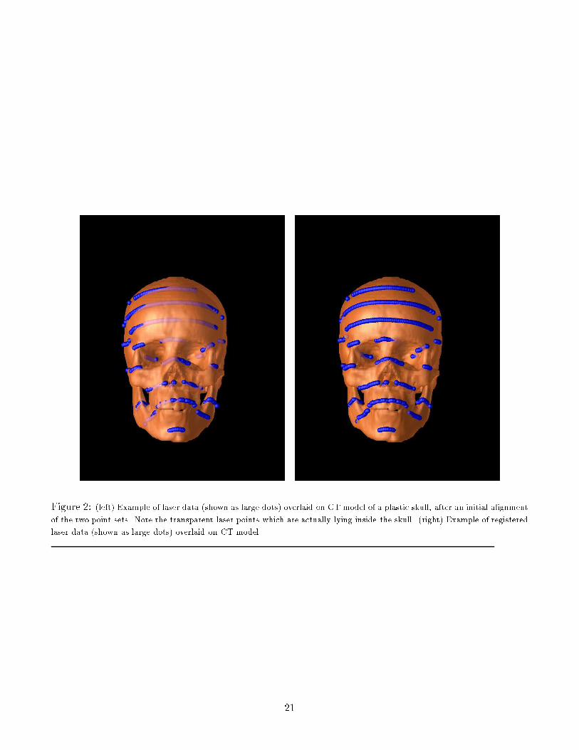
Figure 2: (left) Example of laser data (shown as large dots) overlaid on CT model of a plastic skull, after an initial alignmentof the two point sets. Note the transparent laser points which are actually lying inside the skull. (right) Example of registeredlaser data (shown as large dots) overlaid on CT model.21
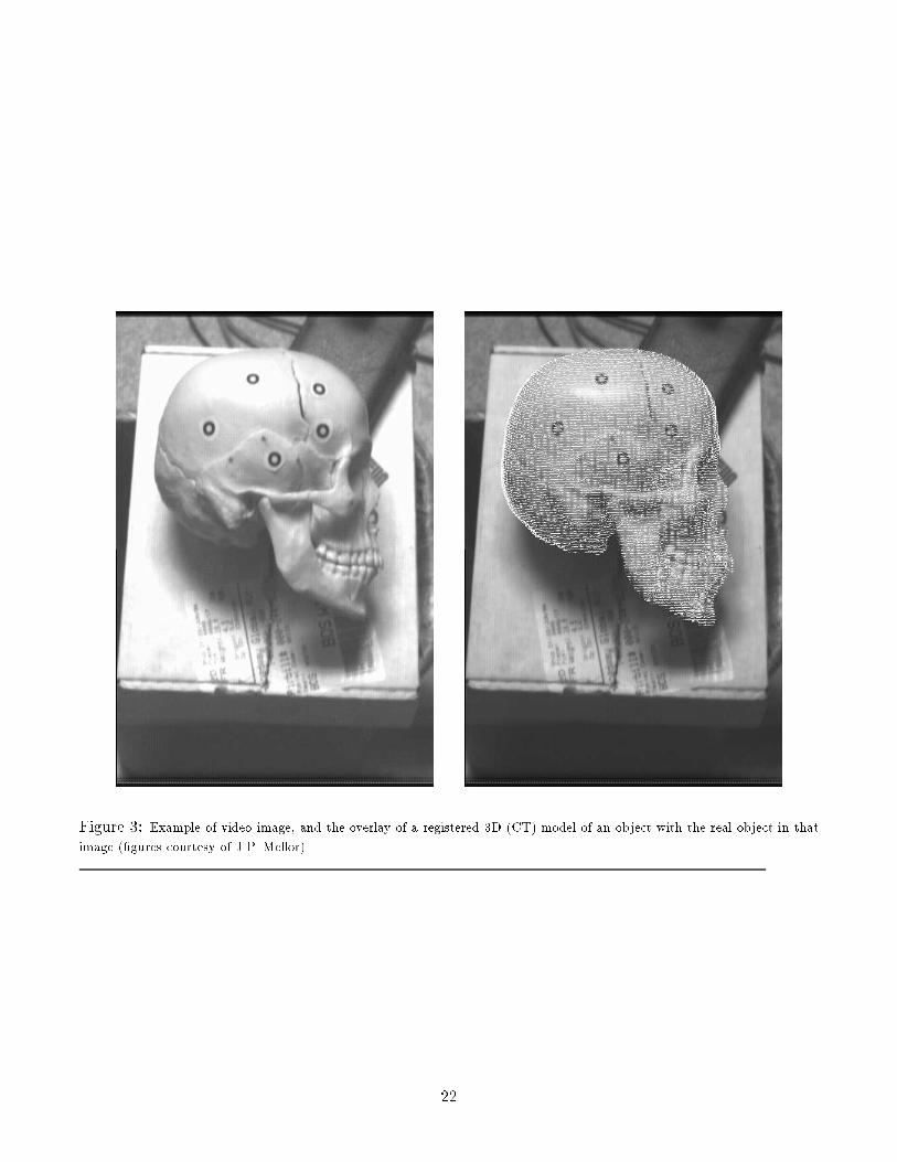
Figure 3: Example of video image, and the overlay of a registered 3D (CT) model of an object with the real object in thatimage (�gures courtesy of J.P. Mellor).22

Figure 4: Examples of registered laser data (shown as large dots) overlaid on CT model.
Figure 5: Example of registered laser data (shown as large dots) overlaid on MRI model.23
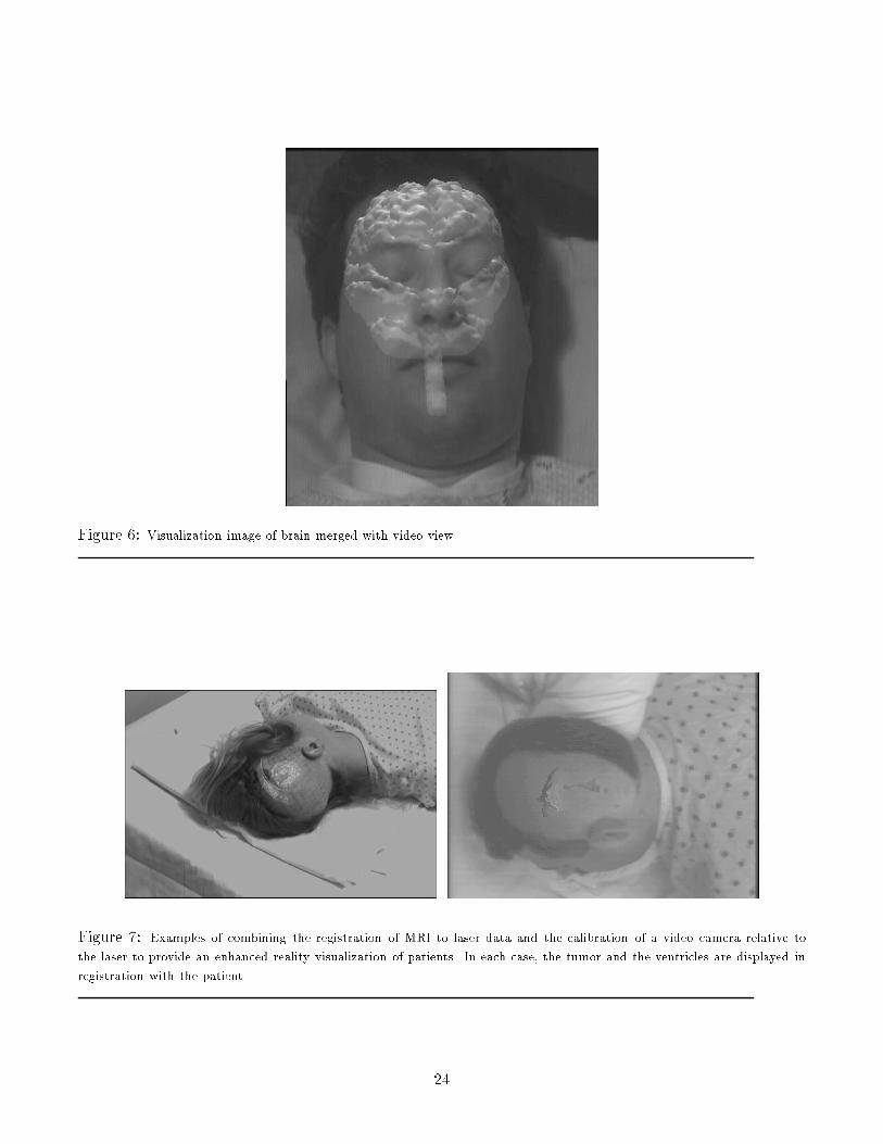
Figure 6: Visualization image of brain merged with video view.Figure 7: Examples of combining the registration of MRI to laser data and the calibration of a video camera relative tothe laser to provide an enhanced reality visualization of patients. In each case, the tumor and the ventricles are displayed inregistration with the patient. 24

Figure 8: RMS error as a function of the sampling of the MRI data. Patient 071594 had an MRI model of 123,725 points,which were matched against 956 laser points. Patient 070194 had an MRI model of 109,641 points, which were matchedagainst 949 laser points. The graphs show the RMS error (in mms) as a function of the fraction of the model actually sampled.25

Figure 9: Example of registering MRI data sets from di�erent times. A subsample set of surface points from one image arematched and overlaid on the surface of the second image.26

Figure 10: A series of MRI slices of a patient taken several weeks apart, over a period of eight months. Shown are theresults of reslicing and normalizing each subsequent MRI scan, relative to the �rst scan, so that, in principle, the same sliceof the anatomy is shown. One can easily see the changes in lesions in the upper left and lower left, over time.27
Related Documents