Available online at www.sciencedirect.com Journal of the European Ceramic Society 32 (2012) 3073–3084 An assessment of in vivo failures of alumina ceramic total hip joint replacements Roger Morrell a,* , Robert Danzer b , Ingrid Miloˇ sev c , Rihard Trebˇ se d a Materials Division, National Physical Laboratory, Teddington, Middlesex TW11 0LW, UK b Institut für Struktur und Funktionskeramik, Montanuniversität Leoben, Peter-Tunner-Strasse 5, A-8700 Leoben, Austria c Physical and Organic Chemistry Dept., Institut Joˇ zef Stefan, Jamova 39, SI-1000 Ljubljana, Slovenia d Orthopaedic Hospital Valdoltra, Jadranska c. 31, SI-6280 Ankaran, Slovenia Received 24 October 2011; received in revised form 5 April 2012; accepted 12 April 2012 Available online 8 May 2012 Abstract Several cases of alumina ceramic hip replacement failures are reviewed fractographically. Three main findings are illustrated. Firstly, there is evidence that surgeons can damage the femoral head bore surface during surgery. Secondly, three of the failures described are of extended neck designs which are weaker than those of normal or short length in axial laboratory testing. Under physiological loading, such geometry can lead to levering forces, inappropriate localized contact with the metallic stem and stress concentrations. Delayed failure can ensue, with a fracture pattern quite different from that seen in conventional uniaxial testing. Thirdly, while some failures show head bore surfaces which are clean apart from metallic witness marking, others show brown stains and white deposits suggesting poor conformal contact. We suspect either stems become damaged during surgery before mounting the head or entrapment of debris, pointing to handling care and cleanliness varying between hospitals. Crown Copyright © 2012 Published by Elsevier Ltd. All rights reserved. Keywords: Biomedical applications; Al 2 O 3 ; Fracture; Surfaces 1. Introduction Ceramic femoral heads based on fine-grained alumina ceram- ics of high purity and near theoretical density have now a long and generally successful history of use in hip replace- ment surgery, and acetabular liners of the same material are also widely employed, e.g. 1–5 Femoral heads are usually mounted on a conical taper at the end of the metallic femoral stem, and acetabular shells may either be of hemispherical type, typically encapsulated within hemispherical high-density polyethylene, in turn held captive within a titanium alloy shell, or may be a direct taper lock fit inside a titanium alloy shell. Despite strong efforts to ensure high quality by the ceramic manufactur- ers and orthopaedic suppliers, 3,4 there remains a small fraction of implants that fail unexpectedly after a limited time in the patient. 4 Such failures cause patient distress, and involve urgent * Corresponding author. Tel.: +44 208 943 6381; fax: +44 208 943 2989. E-mail address: [email protected] (R. Morrell). and expensive remedial surgery. Understanding the conditions that lead to such failures is a key element in improving implant reliability. The general quality of the basic ceramic material is governed by ISO 6474-1, which defines the minimum values of parame- ters such as purity, grain size and density. 3 When test bars of the material are prepared and finished in defined ways, the average short-term fracture strength determined in a standardized flex- ure test should be in excess of a minimum value. Such a test can be used to define whether the employed powder raw mate- rial, having passed through the various stages of shaping and sintering, produces a ceramic with an acceptably low density of abnormal and inappropriate strength-limiting features, such as large pores, agglomerates with associated cracks, impurity zones, observable using fractography. 6 The preparation of a ceramic femoral head or acetabular shell liner from an appropriate raw powder according to the desired design not only involves the preparation of a complex shape, but also several machining processes, before the final polishing of the articulating surface. In general these machining processes are different from those employed for the baseline materials testing, 0955-2219/$ – see front matter. Crown Copyright © 2012 Published by Elsevier Ltd. All rights reserved. http://dx.doi.org/10.1016/j.jeurceramsoc.2012.04.019

Welcome message from author
This document is posted to help you gain knowledge. Please leave a comment to let me know what you think about it! Share it to your friends and learn new things together.
Transcript

Available online at www.sciencedirect.com
Journal of the European Ceramic Society 32 (2012) 3073–3084
An assessment of in vivo failures of alumina ceramic totalhip joint replacements
Roger Morrell a,∗, Robert Danzer b, Ingrid Milosev c, Rihard Trebse d
a Materials Division, National Physical Laboratory, Teddington, Middlesex TW11 0LW, UKb Institut für Struktur und Funktionskeramik, Montanuniversität Leoben, Peter-Tunner-Strasse 5, A-8700 Leoben, Austria
c Physical and Organic Chemistry Dept., Institut Jozef Stefan, Jamova 39, SI-1000 Ljubljana, Sloveniad Orthopaedic Hospital Valdoltra, Jadranska c. 31, SI-6280 Ankaran, Slovenia
Received 24 October 2011; received in revised form 5 April 2012; accepted 12 April 2012Available online 8 May 2012
Abstract
Several cases of alumina ceramic hip replacement failures are reviewed fractographically. Three main findings are illustrated. Firstly, there isevidence that surgeons can damage the femoral head bore surface during surgery. Secondly, three of the failures described are of extended neckdesigns which are weaker than those of normal or short length in axial laboratory testing. Under physiological loading, such geometry can leadto levering forces, inappropriate localized contact with the metallic stem and stress concentrations. Delayed failure can ensue, with a fracturepattern quite different from that seen in conventional uniaxial testing. Thirdly, while some failures show head bore surfaces which are clean apartfrom metallic witness marking, others show brown stains and white deposits suggesting poor conformal contact. We suspect either stems becomedamaged during surgery before mounting the head or entrapment of debris, pointing to handling care and cleanliness varying between hospitals.Crown Copyright © 2012 Published by Elsevier Ltd. All rights reserved.
Keywords: Biomedical applications; Al2O3; Fracture; Surfaces
1. Introduction
Ceramic femoral heads based on fine-grained alumina ceram-ics of high purity and near theoretical density have now along and generally successful history of use in hip replace-ment surgery, and acetabular liners of the same material are alsowidely employed, e.g.1–5 Femoral heads are usually mountedon a conical taper at the end of the metallic femoral stem, andacetabular shells may either be of hemispherical type, typicallyencapsulated within hemispherical high-density polyethylene,in turn held captive within a titanium alloy shell, or may bea direct taper lock fit inside a titanium alloy shell. Despitestrong efforts to ensure high quality by the ceramic manufactur-ers and orthopaedic suppliers,3,4 there remains a small fractionof implants that fail unexpectedly after a limited time in thepatient.4 Such failures cause patient distress, and involve urgent
∗ Corresponding author. Tel.: +44 208 943 6381; fax: +44 208 943 2989.E-mail address: [email protected] (R. Morrell).
and expensive remedial surgery. Understanding the conditionsthat lead to such failures is a key element in improving implantreliability.
The general quality of the basic ceramic material is governedby ISO 6474-1, which defines the minimum values of parame-ters such as purity, grain size and density.3 When test bars of thematerial are prepared and finished in defined ways, the averageshort-term fracture strength determined in a standardized flex-ure test should be in excess of a minimum value. Such a testcan be used to define whether the employed powder raw mate-rial, having passed through the various stages of shaping andsintering, produces a ceramic with an acceptably low densityof abnormal and inappropriate strength-limiting features, suchas large pores, agglomerates with associated cracks, impurityzones, observable using fractography.6
The preparation of a ceramic femoral head or acetabular shellliner from an appropriate raw powder according to the desireddesign not only involves the preparation of a complex shape, butalso several machining processes, before the final polishing ofthe articulating surface. In general these machining processes aredifferent from those employed for the baseline materials testing,
0955-2219/$ – see front matter. Crown Copyright © 2012 Published by Elsevier Ltd. All rights reserved.http://dx.doi.org/10.1016/j.jeurceramsoc.2012.04.019
3074 R. Morrell et al. / Journal of the European Ceramic Society 32 (2012) 3073–3084
and various regions of the components are subject to rotationalgrinding or polishing processes, or can even be left in the green-machined and as-fired condition. The choice of tooling for thisoperation is often a balance between, on the one hand, optimumsurface quality and geometry according to the designed shapeand tolerances, and on the other, the cost-effectiveness of the pro-cess. By their very nature, all abrasive machining processes onceramics introduce both machining flaws and surface residualstresses, and thus the strength characteristics of an individualfemoral head are very much defined by the particular processand finishing route employed. Ultimate burst strength tests andfatigue tests, usually performed on a particular design and pro-cess route using axial loading through an appropriately matingmetallic test stem cone, are made to provide a one-off perfor-mance evaluation against minimum criteria established for thesetests. Then, to ensure that the individual finished heads do notcontain large manufacturing defects, quality assurance testingtypically includes fluorescent dye inspection for cracks and othersurface connected defects, and commonly also a form of prooftest in which the head bore is subjected to internal pressuriza-tion for a short period of time to simulate the stress distributionthat might be expected from the taper fit onto the metallicstem.7
With particular regard to ceramic femoral heads, the generaltrend has been towards some standardization of the bore taperangle and the tolerable mismatch to the metallic cone. The usualintention is that the metal cone first makes strong contact withthe head near the inner end of the head bore, and then as loadingis increased plastic deformation of the metal cone permits theextension of the contact region back towards the bore mouth.In an axial fracture test there is normally complete contact withthe bore before the point of fracture, thus spreading the con-tact stresses over a large area.8 The plastic deformation in themetal cone may in fact be enhanced by ridging the cone surfaceto ensure more rapid conformation. The axial force places theceramic head under hoop tensile stress, and higher axial fractureloads are typically obtained with softer, more readily conform-ing titanium alloy cones than with harder cobalt-chrome alloycones. In such tests, fracture normally occurs from the bore sur-face, the highest stressed region. However, in vivo the head maybe variably pre-loaded onto the stem by the surgeon, and thenis subjected to primarily off-axis loading under the action ofpatient body forces.
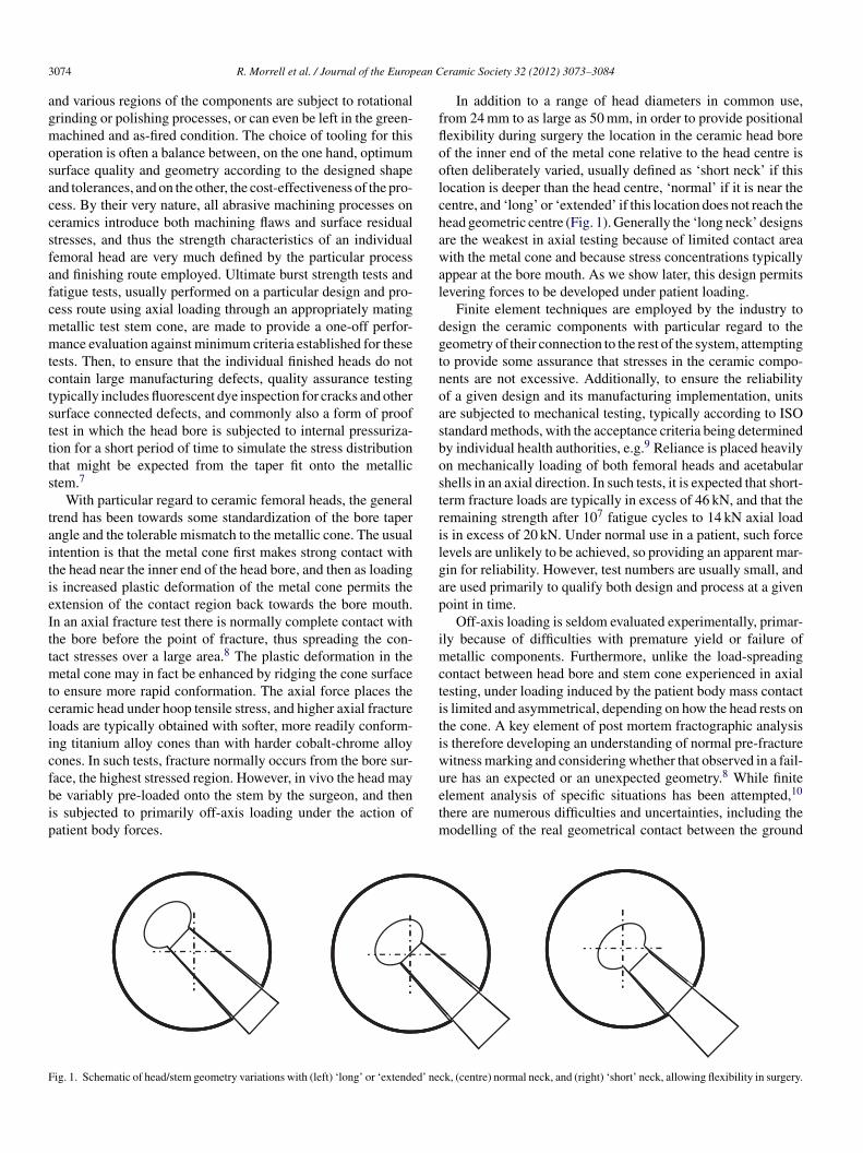
In addition to a range of head diameters in common use,from 24 mm to as large as 50 mm, in order to provide positionalflexibility during surgery the location in the ceramic head boreof the inner end of the metal cone relative to the head centre isoften deliberately varied, usually defined as ‘short neck’ if thislocation is deeper than the head centre, ‘normal’ if it is near thecentre, and ‘long’ or ‘extended’ if this location does not reach thehead geometric centre (Fig. 1). Generally the ‘long neck’ designsare the weakest in axial testing because of limited contact areawith the metal cone and because stress concentrations typicallyappear at the bore mouth. As we show later, this design permitslevering forces to be developed under patient loading.
Finite element techniques are employed by the industry todesign the ceramic components with particular regard to thegeometry of their connection to the rest of the system, attemptingto provide some assurance that stresses in the ceramic compo-nents are not excessive. Additionally, to ensure the reliabilityof a given design and its manufacturing implementation, unitsare subjected to mechanical testing, typically according to ISOstandard methods, with the acceptance criteria being determinedby individual health authorities, e.g.9 Reliance is placed heavilyon mechanically loading of both femoral heads and acetabularshells in an axial direction. In such tests, it is expected that short-term fracture loads are typically in excess of 46 kN, and that theremaining strength after 107 fatigue cycles to 14 kN axial loadis in excess of 20 kN. Under normal use in a patient, such forcelevels are unlikely to be achieved, so providing an apparent mar-gin for reliability. However, test numbers are usually small, andare used primarily to qualify both design and process at a givenpoint in time.
Off-axis loading is seldom evaluated experimentally, primar-ily because of difficulties with premature yield or failure ofmetallic components. Furthermore, unlike the load-spreadingcontact between head bore and stem cone experienced in axialtesting, under loading induced by the patient body mass contactis limited and asymmetrical, depending on how the head rests onthe cone. A key element of post mortem fractographic analysisis therefore developing an understanding of normal pre-fracturewitness marking and considering whether that observed in a fail-ure has an expected or an unexpected geometry.8 While finiteelement analysis of specific situations has been attempted,10
there are numerous difficulties and uncertainties, including themodelling of the real geometrical contact between the ground
Fig. 1. Schematic of head/stem geometry variations with (left) ‘long’ or ‘extended’ neck, (centre) normal neck, and (right) ‘short’ neck, allowing flexibility in surgery.
R. Morrell et al. / Journal of the European Ceramic Society 32 (2012) 3073–3084 3075
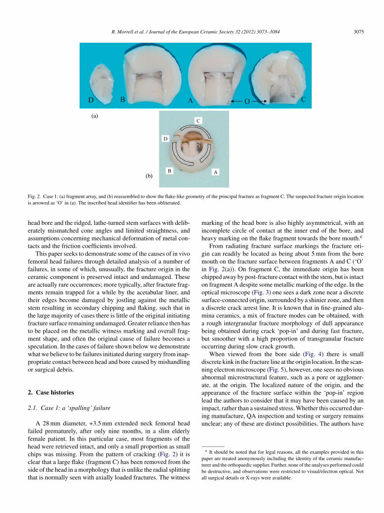
Fig. 2. Case 1: (a) fragment array, and (b) reassembled to show the flake-like geometry of the principal fracture as fragment C. The suspected fracture origin locationis arrowed as ‘O’ in (a). The inscribed head identifier has been obliterated.
head bore and the ridged, lathe-turned stem surfaces with delib-erately mismatched cone angles and limited straightness, andassumptions concerning mechanical deformation of metal con-tacts and the friction coefficients involved.
This paper seeks to demonstrate some of the causes of in vivofemoral head failures through detailed analysis of a number offailures, in some of which, unusually, the fracture origin in theceramic component is preserved intact and undamaged. Theseare actually rare occurrences; more typically, after fracture frag-ments remain trapped for a while by the acetabular liner, andtheir edges become damaged by jostling against the metallicstem resulting in secondary chipping and flaking, such that inthe large majority of cases there is little of the original initiatingfracture surface remaining undamaged. Greater reliance then hasto be placed on the metallic witness marking and overall frag-ment shape, and often the original cause of failure becomes aspeculation. In the cases of failure shown below we demonstratewhat we believe to be failures initiated during surgery from inap-propriate contact between head and bore caused by mishandlingor surgical debris.
2. Case histories
2.1. Case 1: a ‘spalling’ failure
A 28 mm diameter, +3.5 mm extended neck femoral headfailed prematurely, after only nine months, in a slim elderlyfemale patient. In this particular case, most fragments of thehead were retrieved intact, and only a small proportion as smallchips was missing. From the pattern of cracking (Fig. 2) it isclear that a large flake (fragment C) has been removed from theside of the head in a morphology that is unlike the radial splittingthat is normally seen with axially loaded fractures. The witness
marking of the head bore is also highly asymmetrical, with anincomplete circle of contact at the inner end of the bore, andheavy marking on the flake fragment towards the bore mouth.e
From radiating fracture surface markings the fracture ori-gin can readily be located as being about 5 mm from the boremouth on the fracture surface between fragments A and C (‘O’in Fig. 2(a)). On fragment C, the immediate origin has beenchipped away by post-fracture contact with the stem, but is intacton fragment A despite some metallic marking of the edge. In theoptical microscope (Fig. 3) one sees a dark zone near a discretesurface-connected origin, surrounded by a shinier zone, and thena discrete crack arrest line. It is known that in fine-grained alu-mina ceramics, a mix of fracture modes can be obtained, witha rough intergranular fracture morphology of dull appearancebeing obtained during crack ‘pop-in’ and during fast fracture,but smoother with a high proportion of transgranular fractureoccurring during slow crack growth.
When viewed from the bore side (Fig. 4) there is smalldiscrete kink in the fracture line at the origin location. In the scan-ning electron microscope (Fig. 5), however, one sees no obviousabnormal microstructural feature, such as a pore or agglomer-ate, at the origin. The localized nature of the origin, and theappearance of the fracture surface within the ‘pop-in’ regionlead the authors to consider that it may have been caused by animpact, rather than a sustained stress. Whether this occurred dur-ing manufacture, QA inspection and testing or surgery remainsunclear; any of these are distinct possibilities. The authors have
e It should be noted that for legal reasons, all the examples provided in thispaper are treated anonymously including the identity of the ceramic manufac-turer and the orthopaedic supplier. Further, none of the analyses performed couldbe destructive, and observations were restricted to visual/electron optical. Notall surgical details or X-rays were available.

3076 R. Morrell et al. / Journal of the European Ceramic Society 32 (2012) 3073–3084
Fig. 3. Case 1: optical micrograph of the suspected fracture origin on Fragment A (a) under grazing incidence illumination from the left, and (b) under normalincidence. Note the sharp boundary of a semielliptical feature at the right side (white arrows), and radiating hackle centrally below it (white arrows). Metal contactmarks decorate the fractured bore edge.
insufficient information to assess whether, if developed duringmanufacture, such a pre-crack would have been detected by QAor proof-testing.
It is believed that under physiological loading conditions theextended neck design has caused the strongly asymmetric metal-lic witness marking seen in Fig. 2 in which the line of action ofbodyweight forces lies through the ball centre, and beyond thelocation of the inner end of ‘long neck’ cone contact. This pro-vides a levering moment on the head/cone contact region, andhence produces highly asymmetric stressing conditions on thehead bore, as shown schematically in Fig. 6, causing the under-side of the head to flake. Fracture of the rest of the head hasfollowed.
It is difficult to assess the stress distribution that this type ofvarying physiological loading applies to the femoral head. Thereis probably a combination of inhomogeneous hoop tension andlocalized contact stresses. Taking the typical fast fracture tough-ness of this type of alumina as 3.5 MPa m1/2, at the arrest lineof radius 750 !m the stress to cause further crack propagation
Fig. 4. Case 1: fragment A, (a) same region as in Fig. 2 but viewed from boresurface to show the fracture line along bore at the suspected origin; initiatingfeature arrowed. The bright lines are reflective metal marks on the bore.
would have been only 100 MPa.11,12 So once a small crack ispopped in, only a relatively low stress is required to propagateit catastrophically, much less than the expected failure stress ofundamaged material, typically 400 MPa or more. This bringsinto question the ‘design’ stress limit that has been used, andhow the stress is computed for off-axis loading conditions.
2.2. Case 2: surgically introduced damage
In this case the right hip of a 120 kg middle-aged male patientwas replaced using a normal length 28 mm alumina ceramichead. Following the development of pain on hospital release, X-ray evaluation showed that fracture must have occurred shortlyafter implantation during initial recuperation. Following revi-sion surgery it was found that the fracture must have displayedrather greater violence than in Case 1, resulting in five principalfragments with stronger fracture hackle marking. The initiatingfracture origin is marked in Fig. 7, is near the bore mouth, andhas resulted in a distinct fracture mirror region surrounding byradiating hackle to produce a near-axial planar split in the head.In this case there is a continuous narrow ring of metallic wit-ness marking at the inner end of the head bore, and some stronglocalized marking near the fracture origin location.
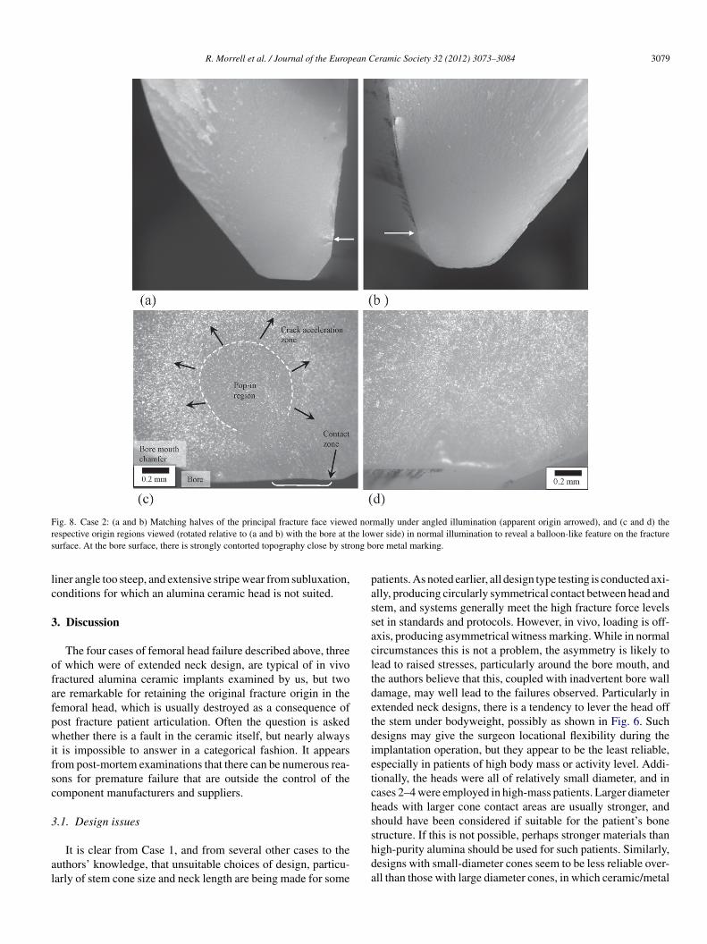
Examination of the fracture surface near the bore mouth(Fig. 8) reveals the fracture origin to be at a balloon-like fea-ture in the reflectivity of the surface, coupled with fracture planetortuosity near to the bore surface. As in Case 1, it is believedthat the dull areas in Fig. 8(b and c) are therefore a result of pre-crack pop-in from the bore surface, and the shinier surroundingregions are a result of later rapid growth of the pre-crack eitherfrom surgical head pre-loading or when the head was stressedby bodyweight. It seems highly unlikely that a head would havebeen supplied with such damage, since it would not have sur-vived the manufacturer’s dye-testing examination and proof testafter all machining stages. Secondary damage can be excludedbecause the patterns on the two halves match exactly, and thiswould not occur if it were caused by secondary chipping.
In this particular case, medical discussions revealed that diffi-culties were incurred during surgery of the particularly muscular
R. Morrell et al. / Journal of the European Ceramic Society 32 (2012) 3073–3084 3077
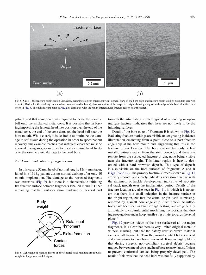
Fig. 5. Case 1: the fracture origin region viewed by scanning electron microscopy; (a) general view of the bore edge and fracture origin with its boundary arrowedin white. Radial hackle marking is clear (directions arrowed in black); (b) closer view of the suspected origin showing a region at the edge of the bore identified as anotch in Fig. 3. The dull fracture zone in Fig. 2(b) correlates with the rough intergranular fracture region near the notch.
patient, and that some force was required to locate the ceramicball onto the implanted metal cone. It is possible that in forc-ing/impacting the femoral head into position over the end of themetal cone, the end of the cone damaged the head ball near thebore mouth. While clearly it is desirable to minimize the dam-age to soft tissue during the operation in order to speed patientrecovery, this example teaches that sufficient clearance must beallowed during surgery in order to place a ceramic head freelyonto the stem to avoid damage to the head bore.
2.3. Case 3: indications of surgical error
In this case, a 32 mm head of normal length, 12/14 mm taper,failed in a 119 kg patient during normal walking after only 10months implantation. The damage to the retrieved fragmentswas extensive (Fig. 9), but there is a characteristic initiatingflat fracture surface between fragments labelled E and F. Otherremaining matched surfaces show evidence of flexural curl
Fig. 6. Schematic of rotation forces on the femoral head resulting from body-weight in long-neck head designs.
towards the articulating surface typical of a bending or open-ing type fracture, indicative that these are not likely to be theinitiating surfaces.
Detail of the bore edge of Fragment E is shown in Fig. 10.Radiating fracture markings are visible under grazing incidenceillumination emanating from a point close to a post-fractureedge chip at the bore mouth end, suggesting that this is thefracture origin location. The bore surface has only a fewmetallic witness marks from the stem contact, and these areremote from the suspected fracture origin, none being visiblenear the fracture origin. This latter region is heavily dec-orated with a hard brownish deposit. This type of depositis also visible on the bore surfaces of fragments A and B(Figs. 9 and 12). The primary fracture surfaces shown in Fig. 11are very smooth, and clearly indicate a very slow fracture withthe minimum of hackle development, indicative of subcriti-cal crack growth over the implantation period. Details of thefracture location are also seen in Fig. 11, in which it is appar-ent that there is a small inflection in the fracture surface inthe origin region, but that the actual origin itself is missing,removed by a small bore edge chip. Such crack-line inflec-tions have been seen in axial strength testing, and are generallyattributable to circumferential machining microcracks that dur-ing propagation under hoop tensile stress twist towards the axialplane.8
Fig. 12 provides views of the bore surface of all the majorfragments. It is clear that there is very limited original metallicwitness marking, but that the patchy reddish-brown materialexists on all fragments. Thus the normal contact between headand cone seems to have been prevented. It seems highly likelythat during surgery, non-compliant surgical debris becametrapped between metal cone and head bore to an extent sufficientto prevent conformal contact being properly developed. Theresult of this was that the head bore was not fully supported by

3078 R. Morrell et al. / Journal of the European Ceramic Society 32 (2012) 3073–3084
Fig. 7. Case 2: (a) sequential array of fragments, (b) origin at the lower bore, and (c) fragments placed together illustrating unusual metallic witness marking nearthe fracture origin.
the metallic stem, and only local contacts were likely to exist,with resulting unknown stress concentrations acting either ona typical, normal pre-existing machining microcrack or onbore damage during surgery. Subcritical growth under patientbodyweight then eventually led to fracture.
2.4. Case 4: indications of surgical error
This case is of a 28 mm extended neck ceramic head andmatching ceramic acetabular liner implanted in an elderly butactive male patient of weight 106 kg. The head is extensivelydamaged, but from the shape of the fragments shows evidenceof having first simply split into two roughly equal parts (Fig. 13),with later secondary flaking. This suggests a very low fracturestress and hence probably extensive subcritical crack growth.However, there is very little original fracture surface remain-ing undamaged, and these regions were so smooth that eventhe general location of the fracture origin could not be deter-mined from microhackle. As with Case 3 there is very little
metallic witness marking in the head bore, but there are sig-nificant deposits of white or reddish-brown material replicatingthe ridges on the metallic stem (Fig. 14). Again, like Case 3, itseems likely that entrapped non-compliant surgical debris pre-vented the head from properly locating on the stem, resulting instress concentrations.
The femoral head also showed an extensive stripe wear scar(Fig. 15) resulting from subluxation,13 with evidence of impactnear the rim of the acetabular liner. The ceramic liner itself wasextensively damaged (Fig. 16), probably after head fracture, byimpact of the stem end directly on the articulating surface. Thedamage is strongly focused towards one edge, suggesting thatthe liner outer shell may have been implanted at a fairly steepinclination. The stripe wear scar (arrowed in Fig. 16, but not eas-ily photographed) is also strongly offset. Whether subluxationplayed a role in the failure via additional impact stresses, or isincidental, is not clear.
Overall this case illustrates several aspects where surgery mayhave been the cause of failure: entrapment of debris, acetabular
R. Morrell et al. / Journal of the European Ceramic Society 32 (2012) 3073–3084 3079
Fig. 8. Case 2: (a and b) Matching halves of the principal fracture face viewed normally under angled illumination (apparent origin arrowed), and (c and d) therespective origin regions viewed (rotated relative to (a and b) with the bore at the lower side) in normal illumination to reveal a balloon-like feature on the fracturesurface. At the bore surface, there is strongly contorted topography close by strong bore metal marking.
liner angle too steep, and extensive stripe wear from subluxation,conditions for which an alumina ceramic head is not suited.
3. Discussion
The four cases of femoral head failure described above, threeof which were of extended neck design, are typical of in vivofractured alumina ceramic implants examined by us, but twoare remarkable for retaining the original fracture origin in thefemoral head, which is usually destroyed as a consequence ofpost fracture patient articulation. Often the question is askedwhether there is a fault in the ceramic itself, but nearly alwaysit is impossible to answer in a categorical fashion. It appearsfrom post-mortem examinations that there can be numerous rea-sons for premature failure that are outside the control of thecomponent manufacturers and suppliers.
3.1. Design issues
It is clear from Case 1, and from several other cases to theauthors’ knowledge, that unsuitable choices of design, particu-larly of stem cone size and neck length are being made for some
patients. As noted earlier, all design type testing is conducted axi-ally, producing circularly symmetrical contact between head andstem, and systems generally meet the high fracture force levelsset in standards and protocols. However, in vivo, loading is off-axis, producing asymmetrical witness marking. While in normalcircumstances this is not a problem, the asymmetry is likely tolead to raised stresses, particularly around the bore mouth, andthe authors believe that this, coupled with inadvertent bore walldamage, may well lead to the failures observed. Particularly inextended neck designs, there is a tendency to lever the head offthe stem under bodyweight, possibly as shown in Fig. 6. Suchdesigns may give the surgeon locational flexibility during theimplantation operation, but they appear to be the least reliable,especially in patients of high body mass or activity level. Addi-tionally, the heads were all of relatively small diameter, and incases 2–4 were employed in high-mass patients. Larger diameterheads with larger cone contact areas are usually stronger, andshould have been considered if suitable for the patient’s bonestructure. If this is not possible, perhaps stronger materials thanhigh-purity alumina should be used for such patients. Similarly,designs with small-diameter cones seem to be less reliable over-all than those with large diameter cones, in which ceramic/metal

3080 R. Morrell et al. / Journal of the European Ceramic Society 32 (2012) 3073–3084
Fig. 9. Case 3: fragment array with the major fragments in sequence, and a large quantity of minor fragments. Note the flat initiating fracture face between fragmentsE and F.
contact is spread over a much larger area. An improvedevaluation using off-axis testing appears to be needed to evaluatethe risks properly.
3.2. Implementation issues
While microstructural defects, such as large pores, agglomer-ates, or inclusions are possible in all ceramics, the methodologiesadopted in powder production, binder control, powder pressing,and firing of bio-grade aluminas are intended to reduce the riskof such features being strength controlling (e.g.3). In axial ulti-mate strength testing of components, seldom is the strength limitassociated with such a feature. It is far more likely that damage
introduced by post-firing machining (and occasionally in ‘green’machining before the firing step) controls the obtained strength.In most products, most of the surface area has undergoneabrasive machining processes, leaving the surface with somedegree of compressive residual stress but also microcrackingdamage. We have found that the vast majority of in vivo fail-ures have fracture origins located at the bore surface, or at thebore mouth (usually with destroyed origins and locations thushaving to be inferred from the directions of fine-scale fracturemarkings). Controlling the machining damage in this region istherefore critical.7
As described in the introduction, the ceramic/metal inter-face with its taper angle mismatch is a critical element of both
Fig. 10. Case 3: photomontages of bore mouth edge of fragment E showing (upper sequence) radiating fracture markings from the bore edge, marked with blackarrows, and (lower sequence) organic/calcareous deposits on the corresponding bore surface with limited metal marking (white arrows).

R. Morrell et al. / Journal of the European Ceramic Society 32 (2012) 3073–3084 3081
Fig. 11. Case 3: very flat, almost featureless fracture surface with detail of bore edge at the fracture origin, (left) under side illumination, (right) under normalillumination. (It was not permitted to coat the fragments to improve contrast.)
the overall design and its implementation, usually by differentmanufacturers, with strong reliance of matching metrologicalstandards for quality assurance.7 By the nature of the machin-ing processes used and the geometry of the respective parts,the required straightness, roundness and smoothness of the headbore taper is generally easier to achieve than that of the metalliccomponent. Achieving proper conformal contact on assemblyand loading is critical in optimizing the strength of the unit.Fractographic assessment of axially loaded test head fracturesshows that in the vast majority of cases origins correspondwith pre-existing machining microcracks that grow under stress.Inappropriate surgical practice, such as that exemplified byCases 3 and 4, prevents such conformal contact being achieved,and leads to stress concentrations and premature failure.
3.3. Surgical issues
In the first two of the above cases, there is no obviousmicrostructural fault at the fracture origin in the ceramic mate-rial that clearly originates from the manufacturing process. Themost likely explanation is of additional damage introduced dur-ing surgery. In particular, in Case 2 we know that the handlingof the head by levering it over the stem end could well haveintroduced some damage. Then, when loaded physiologically,if the developed tensile stress distribution coincides with thedamage location and is sufficiently intense, surface microcrackswill propagate. As the first two examples show, even the smallsize of such ‘pop-in’ cracks can cause a large drop in resid-ual strength. Significant damage to the head during surgery,
Fig. 12. Case 3: Very limited original metallic bore witness marking on those fragments which have bore surface.

3082 R. Morrell et al. / Journal of the European Ceramic Society 32 (2012) 3073–3084
Fig. 13. Case 4: femoral head fragment array showing major initial fragmentsA and B, and several smaller flakes developed after primary fracture which maynot be arranged in the correct sequence owing to damage.
particularly to the bore and the bore mouth regions, must beavoided.
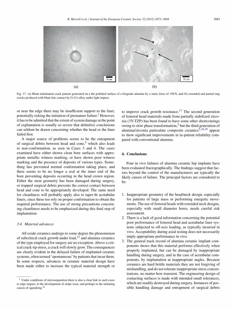
As a demonstration of the risk of inappropriate contact dam-age, Fig. 17a shows the cracks that result of applying a staticforce of only 150 N to a blunt diamond indenter contacting thepolished surface of a biograde alumina. The half-penny shapedcracks that are developed have dimensions similar to the pop-in crack in Fig. 3. It does not require the contact to be hard tocause damage. Blunt indentation with softer materials, partic-ularly under impact conditions, is known to damage ceramics,more so the lower the fracture toughness. Fig. 17b shows thedamage to a similar surface caused by a blunt line contact withCo-Cr alloy under mild angled impact conditions. Other exam-ples include the chipping of diamond by WC and steel tools,14
and damage to silicon nitride forming rolls by impact from softsteel bars.15
Fig. 14. Case 4: bore surface of fragment A showing white and reddish brownridged deposits replicating the ridged metallic stem, but no significant metalliccircumferential marking. The white band of deposit at the top is above themetallic stem end.
Fig. 15. Case 4: extensive stripe wear scar highlighted using a felt-tip pen.
Plastic damage to the metallic cone before locating theceramic head must also be avoided, since this will also impedethe correct conformation of contacting surfaces. Often thepost fracture evaluator does not have access to the metalliccone and stem, which normally is not replaced during revisionunless essential (typically a metallic head is substituted for theceramic one, and a new ceramic one should never be placeddirectly onto a damaged metallic cone without an interveningmetal sleeve5). It might be thought that this would seriouslyimpede any fractographic investigation, but in practice the postfracture damage has usually obliterated any original dimen-sions or evidence of implantation damage, so little evidence isprovided.
In Case 4, the acetabular liner damage is centred at a locationvery close to the edge. This feature has also been seen in numer-ous explants with both encapsulated and taper-fit liners. As withceramic heads, liners are seldom if ever tested off-axis, and there-fore the real reliability of the performance when implanted at toosteep an angle is not known. When concentrating the loading at
Fig. 16. Case 4: axial view of the still-encapsulated acetabular liner showing astrong offset to the region of impact damage with the stem end, and of the stripewear scar (inner boundary arrowed).
R. Morrell et al. / Journal of the European Ceramic Society 32 (2012) 3073–3084 3083
Fig. 17. (a) Blunt indentation crack pattern generated on a the polished surface of a biograde alumina by a static force of 150 N, and (b) extended and partial ringcracks produced with blunt line contact by Cr-Co alloy under light impact.
or near the edge there may be insufficient support to the liner,potentially risking the initiation of premature failure.f However,it has to be admitted that the extent of system damage at the pointof explantation is usually so severe that definitive conclusionscan seldom be drawn concerning whether the head or the linerfailed first.
A major source of problems seems to be the entrapmentof surgical debris between head and cone,5 which also leadsto non-conformation, as seen in Cases 3 and 4. The casesexamined have either shown clean bore surfaces with appro-priate metallic witness marking, or have shown poor witnessmarking and the presence of deposits of various types. Some-thing has prevented normal conformation taking place, andthere seems to be no longer a seal at the inner end of thebore preventing deposits occurring in the head crown region.Either the stem geometry has been damaged during surgery,or trapped surgical debris prevents the correct contact betweenhead and cone to be appropriately developed. The same needfor cleanliness will probably apply also to taper-fit acetabularliners, since these too rely on proper conformation to obtain therequired performance. The use of strong precautions concern-ing cleanliness needs to be emphasized during this final step ofimplantation.
3.4. Material advances
All oxide ceramics undergo to some degree the phenomenonof subcritical crack growth under load,12 and alumina ceramicsof the type employed for surgery are no exception. Above a crit-ical crack-tip stress, a crack will slowly grow. The consequencesare clearly evident in the delayed failure of implanted ceramicsystems, often termed ‘spontaneous’ by patients that incur them.In some respects, advances in ceramic material design havebeen made either to increase the typical material strength or
f Under conditions of microseparation there is also a clear link in such casesto edge impact, to the development of stripe wear, and perhaps to the initiatingcauses of squeaking.16
to improve crack growth resistance.17 The second generationof femoral head materials made from partially stabilized zirco-nia (3Y-TZP) has been found to have some other shortcomingsowing to slow phase transformation,5 but the third generation ofalumina/zirconia particulate composite ceramics5,18,19 appearto show significant improvements in in-patient reliability com-pared with conventional alumina.
4. Conclusions
Four in vivo failures of alumina ceramic hip implants havebeen evaluated fractographically. The findings suggest that fac-tors beyond the control of the manufacturers are typically thelikely causes of failure. The principal factors are considered tobe:
1. Inappropriate geometry of the head/neck design, especiallyfor patients of large mass or performing energetic move-ments. The use of femoral heads with extended neck designs,especially with small diameter bores, needs careful riskassessment.
2. There is a lack of good information concerning the potentialpoor performance of femoral head and acetabular liner sys-tems subjected to off-axis loading, as typically incurred invivo. Acceptability during axial testing does not necessarilyimply appropriate performance in vivo.
3. The general track record of alumina ceramic implant com-ponents shows that this material performs effectively whenproperly implanted, but can be damaged by inappropriatehandling during surgery, and in the case of acetabular com-ponents, by implantation at inappropriate angles. Becauseceramics are hard brittle materials they are not forgiving ofmishandling, and do not tolerate inappropriate stress concen-trations, no matter how transient. The engineering design ofcontacting surfaces is made with intended small tolerances,which are readily destroyed during surgery. Instances of pos-sible handling damage and entrapment of surgical debris

3084 R. Morrell et al. / Journal of the European Ceramic Society 32 (2012) 3073–3084
between ceramic head bore and metallic cone have beenillustrated as causing premature failure.
Acknowledgements
Grateful thanks are due to persons anonymous for permissionto publish the results of Cases 1, 3 and 4.
References
1. Rieger W. Aluminium und Zirkonoxidkeramik in der Medezin. IndustrieDiamanten Rundschau 1993;2:2–6.
2. Willmann G. Ceramics for total hip replacement – what a surgeon shouldknow. Orthopedics 1998;21:173–7.
3. Willman G. Ceramic femoral head retrieval data. Clin Orthop2000;379:22–8.
4. Rieger W. Ceramics in orthopedics – 30 years of evolution and experience.In: Rieker C, Oberholzer S, Wyss U, editors. Proceedings of the WorldTribology Forum in Orthoplasty. Bern: Verlag Hans Huber; 2001. p. 283–94.
5. Piconi C, Maccauro G, Muratori F, Brach Del Prever E. Alumina and zirconiaceramics in joint replacements. J Appl Biomater Biomech 2003;1:19–32.
6. Danzer R. Mechanical failure of advanced ceramics: the value of fractogra-phy. Key Eng Mater 2002;223:1–18.
7. Morrell R, Hughes S. Factors influencing the reliability of ceramic femoralcomponents. J Eur Ceram Soc 2007;27:1535–41.
8. Morrell R, Byrne L, Murray M. Fractography of ceramic femoral heads.Ceram Trans (USA) 2001;122:253–66.
9. US Food and Drug administration. Guidance Document for thePreparation of Premarket Notification for Ceramic Ball Hip
Systems. www.fda.gov/MedicalDevices/DeviceRegulationandGuidance/GuidanceDocuments/ucm080770.htm.
10. Andrisano A, Dragoni E, Strozzi A. Axisymmetric mechanical analy-sis of ceramic heads for total hip replacement. Proc Inst Mech Eng1990;204:157–67.
11. Danzer R, Lube T, Supancic P, Damani R. Fracture of ceramics. Adv EngMater 2008;10:275–98.
12. Quinn GD. Fractography of ceramics and glasses. Washington: NIST Spe-cial Publication 960-16; 2007.
13. Walter WL, Insley GM, Walter WK, Tuke MA. Edge loading in third gen-eration alumina ceramic-on-ceramic bearings: Stripe wear. J Arthroplasty2004;19:402–13.
14. Morrell R, Danzer R, Supancic P, Harrer W, Puchegger S, Peterlik H. Meso-scale mechanical testing methods for diamond composite materials. Int JRefract Met Hard Mater 2010;28:508–15.
15. Lengauer M, Danzer R. Silicon nitride tools for hot rolling of high alloyedsteel and superalloy wires – crack growth and lifetime prediction. J EurCeram Soc 2008;28:2289–98.
16. Walter WL, Waters TS, Gillies M, Donohoo S, Kurtz SM, Ranawat AS, et al.Squeaking hips. J Bone Joint Surg Am 2008;90(Suppl. 4):102–11.
17. De Aza AH, Chevalier J, Fantozzi G, Schehlb M, Torrecillas R. Crack growthresistance of alumina, zirconia and zirconia toughened alumina ceramics forjoint prostheses. Biomaterials 2002;23(3):937–45.
18. Rack R, Pfaff H-G. A new ceramic material for orthopaedics. In: 5th Inter-national CeramTec Symposium. 2000. pp. 141–145.
19. Rack R, Pfaff H-G. Long-term performance of the alumina matrix com-posite Biolox® Delta. In: Toni A, Willmann G, editors. Bioceramics inJoint Arthroplasty. Stuttgart, New York: Georg Thieme Verlag; 2001. p.103–8.
Related Documents


![Alumina matrix ceramic-nickel composites formed … 30 04.pdf · Processing and Applicationof Ceramics 9 [4] (2015) 199–202 DOI: 10.2298/PAC1504199Z Alumina matrix ceramic-nickel](https://static.cupdf.com/doc/110x72/5b89a96e7f8b9aa81a8ce95e/alumina-matrix-ceramic-nickel-composites-formed-30-04pdf-processing-and-applicationof.jpg)


