1 INTERNATIONAL DESIGN CONFERENCE - DESIGN 2014 Dubrovnik - Croatia, May 19 - 22, 2014. AN APPROACH TO NONLINEAR BEHAVIOUR PREDICTION OF TECHNICAL SYSTEMS K. Osman, M. Štorga and D. Marjanović Keywords: behaviour, prediction, nonlinearity, technical system, system architecture, fuzzy rules 1. Introduction The number of challenges faced by firms in recent years has increased dramatically. Such challenges mainly arise from continued changes in market situations as a result of globalization, quickly reflecting both in international competition, shorter product lifecycles, and technological progress [Simpson et al. 2006]. In addition, customer requirements have been increasingly high, including customized product variants, which firms are to satisfy with their product ranges. To maintain competitiveness, firms should not ignore such requirements [Anggraeni et al. 2013]. Such increased number of product variants implies a greater complexity of the product development processes [Robertson and Ulrich 1998]. One may argue that the crucial factor of an industrial company’s performance arises from its ability to comprehend and operate complex systems, as well as their development processes, and constant adoption of new technologies. Knowledge so acquired should be used as a competitive advantage in product development and improvement. However, this is becoming increasingly difficult nowadays, as a result of a drastic increase in system (product) complexity [Diepold et al. 2010]. So it is therefore necessary to be able to describe the system architecture and to model its behaviour to better understand the system itself [Diepold et al. 2010a]. When creating new or improving existing product variants by changing the system architecture or adding functions or subsystems, we are able to influence its behaviour. However, it is very difficult to identify “good” product architectures [Wyatt et al. 2011]. Designing may be described as a process of transforming a set of needs and requirements into a technical system description [Hubka and Eder 1992], [Hubka and Eder 1988]. In an area determined by user requirements, the designer iteratively advances from an abstract idea and concept to a specifically designed and detailed solution. Its iteration is characterized by a series of loops with alternating solution generation and validation, based on which the designer makes decisions on certain future solutions. The designing process begins with imprecise, incomplete and often contradictory information about the future product and each alternative to the solution is designed as a transformation of a set of criteria and/or requirements into a theoretical or physical solution, including designer’s experience. Decisions made during the preliminary phases of product development have a substantial impact on the product (e.g. product development time in relation to product quality and price). Making such decisions is impeded by uncertainty and vagueness, imminent to initial phases of product development [Stark et al. 2010]. As a result of technological progress and adaptations in use, technical systems may be found in a working environment not included in the initial specification, which results in uncertain working conditions (e.g. operation of an environmental chamber at low external temperatures or operation of a load lifting device as a result of high wind speeds). In addition, the initial phases of product development include many uncertain parameters, which should be considered as such when evaluating product alternatives and making decisions [Kota and Chakabarti

Welcome message from author
This document is posted to help you gain knowledge. Please leave a comment to let me know what you think about it! Share it to your friends and learn new things together.
Transcript
1
INTERNATIONAL DESIGN CONFERENCE - DESIGN 2014
Dubrovnik - Croatia, May 19 - 22, 2014.
AN APPROACH TO NONLINEAR BEHAVIOUR
PREDICTION OF TECHNICAL SYSTEMS
K. Osman, M. Štorga and D. Marjanović
Keywords: behaviour, prediction, nonlinearity, technical system,
system architecture, fuzzy rules
1. Introduction
The number of challenges faced by firms in recent years has increased dramatically. Such challenges mainly arise from continued changes in market situations as a result of globalization, quickly
reflecting both in international competition, shorter product lifecycles, and technological progress
[Simpson et al. 2006]. In addition, customer requirements have been increasingly high, including customized product variants, which firms are to satisfy with their product ranges. To maintain
competitiveness, firms should not ignore such requirements [Anggraeni et al. 2013]. Such increased
number of product variants implies a greater complexity of the product development processes
[Robertson and Ulrich 1998]. One may argue that the crucial factor of an industrial company’s performance arises from its ability to comprehend and operate complex systems, as well as their
development processes, and constant adoption of new technologies. Knowledge so acquired should be
used as a competitive advantage in product development and improvement. However, this is becoming increasingly difficult nowadays, as a result of a drastic increase in system (product) complexity
[Diepold et al. 2010]. So it is therefore necessary to be able to describe the system architecture and to
model its behaviour to better understand the system itself [Diepold et al. 2010a]. When creating new
or improving existing product variants by changing the system architecture or adding functions or subsystems, we are able to influence its behaviour. However, it is very difficult to identify “good”
product architectures [Wyatt et al. 2011].
Designing may be described as a process of transforming a set of needs and requirements into a technical system description [Hubka and Eder 1992], [Hubka and Eder 1988]. In an area determined
by user requirements, the designer iteratively advances from an abstract idea and concept to a
specifically designed and detailed solution. Its iteration is characterized by a series of loops with alternating solution generation and validation, based on which the designer makes decisions on certain
future solutions. The designing process begins with imprecise, incomplete and often contradictory
information about the future product and each alternative to the solution is designed as a
transformation of a set of criteria and/or requirements into a theoretical or physical solution, including designer’s experience. Decisions made during the preliminary phases of product development have a
substantial impact on the product (e.g. product development time in relation to product quality and
price). Making such decisions is impeded by uncertainty and vagueness, imminent to initial phases of product development [Stark et al. 2010]. As a result of technological progress and adaptations in use,
technical systems may be found in a working environment not included in the initial specification,
which results in uncertain working conditions (e.g. operation of an environmental chamber at low external temperatures or operation of a load lifting device as a result of high wind speeds). In addition,
the initial phases of product development include many uncertain parameters, which should be
considered as such when evaluating product alternatives and making decisions [Kota and Chakabarti
2
2009]. Two most influential aspects intertwine in different product development phases, on different
levels: creating the system architecture and parallel valuation of proposed architecture’s behaviour
[Hubka and Eder 1992], [Hansen and Andreasen 2002].
This paper represents an approach to the architecture development for complex technical systems based on their nonlinear behaviour model. It provides us with feedback on the behaviour of proposed
system architectures (more precisely, their subsystems) in two cases. One case is under specified
working conditions, while the other one is under uncertain conditions during system operation. In this case, uncertain conditions are those resulting from external influences (natural uncertainty [Kota and
Chakabarti 2009]). In addition, this approach allows us to model and simulate the behaviour of a
complex nonlinear technical system and test its stability. System modelling by using our mathematical model allows us to take into account the uncertainties resulting from external conditions (e.g. the
impact of external temperature, air pressure or high-speed winds affecting the system). In addition to
all this, it allows us to record the behaviour of the observed system by using fuzzy rules. The approach
has an iterative character, which means it is possible to affect the behaviour of a technical system by adding or removing certain subsystems in its architecture (by changing it). Recording behaviour rules
allows us to improve the present system by adding new behaviour rules.
The next section describes the background and addresses the previous research in connection with the development and validation of system architecture, including uncertain working conditions. This paper
is an extension of such research. Section 3 motivated us to continue this research, while Chapter 4
provides a brief description of the approach, explained on a step-by-step basis, and transfer of information between steps. Section 5 provides a verification of the approach on an example of a load
lifting device. A discussion of the results obtained on such example is provided in Section 6. Section
7, which closes this paper, provides a conclusion of the presented research and possible directions of
future research.
2. Background
Two main approaches known in recent years, which is applies in the development and validation of
alternatives of technical system architectures. One approach is based on Robust Design and methods
developed mostly by [Taguchi 1993], where existing models and product development methods are integrated. The other approach, so-called Multi-Dynamic Mapping [Diepold et al. 2010], [Diepold et
al. 2010] integrates structural and dynamical complexity according to Strogatz [2001], with bilateral
information mapping between the structural domain and the behavioral domain. Both approaches have advantages and flaws that are often manifested in a number of ways, depending on the system domain.
Some of the second approach’s flaws were attempted to be resolved by research in the Osman et al
[2011] paper, directing the the research to the application of the Behaviour Prediction Framework in the development of complex technical systems. BPF approach is based on the Multi-Dynamic
Mapping, where it provides bilateral information mapping by combining the structural model and the
behavioral model (dynamic models) of the technical system. It also eliminates certain flaws of Multi-
Dynamic Mapping such as: the possibility of mathematical subsystem behaviour modeling depending on time, so-called non-stationary model, the possibility of presenting the system in a nonlinear form,
and the possibility of improving the system within the dynamic model by changing the parameters.
This reduces the potential number of iteration steps while seeking a satisfactory solution. The approach is also applicable to large systems. The approach was tested on an environmental chamber
technical system as an example of a highly linear system with substantial delays.
3. Motivation
The product validation and decision making process is particularly important in the conceptual phase of product development. It is in this phase that we are able to avoid potential designing errors and
eliminate them before they spread to later development phases. In product development, it is
particularly important to resolve problems relating to uncertainty resulting from natural impacts (so-called natural uncertainty) [Kota and Chakabarti 2009]. Such problems are very difficult to resolve
without having knowledge of technical system behaviour and the possibilities of their mathematical
modeling. This depends on the technical system’s type and application. Where such situations arise,
3
standard approaches provide unsatisfactory results because they fail to provide a quantitative
comparison between product variants and therefore fail to determine the acceptable situation. In
addition, current product validation processes are becoming increasingly complex. There are multiple
reasons for this, of which we will underscore two according to [Kortler et al. 2012]: primarily, increasingly complex customer requirements and enhanced technical possibilities of the equipment
manufacturer. In addition, multidisciplinarity and integration of several professions (mechanical
engineering, electronics, computing, maintenance) in the development of modern products (such as mechatronic systems) increases the complexity of the validation process [Lindemann 2006]. This
paper aims to present an approach based on the development of technical system architectures
according to their behaviour models. Irrespective of the domain of application, the most important flaw in the approaches referred to in Section 2 of this paper is that neither approach supports a non-
stationary presentation of technical system architecture behaviour. Based on the system’s
mathematical model, prediction of its behaviour, and an assessment of the simulation and system
stability testing quality, we attempted to create a decision making model based on Mamdani-type decision making and recording behaviour by using fuzzy rules. We aimed to apply this to a group of
technical systems according to their behaviour, so-called highly nonlinear systems. A nonlinear
mathematical model can be linearized (approximated by using a linear model) depending on the designated operating mode. This will result in a linear mathematical model where it will be possible to
explain system behaviour in a satisfactory manner in a framework of a selected state of balance
(because linear effects of the system prevail). This paper also contemplates dynamic system models with concentrated parameters.
4. Proposed approach
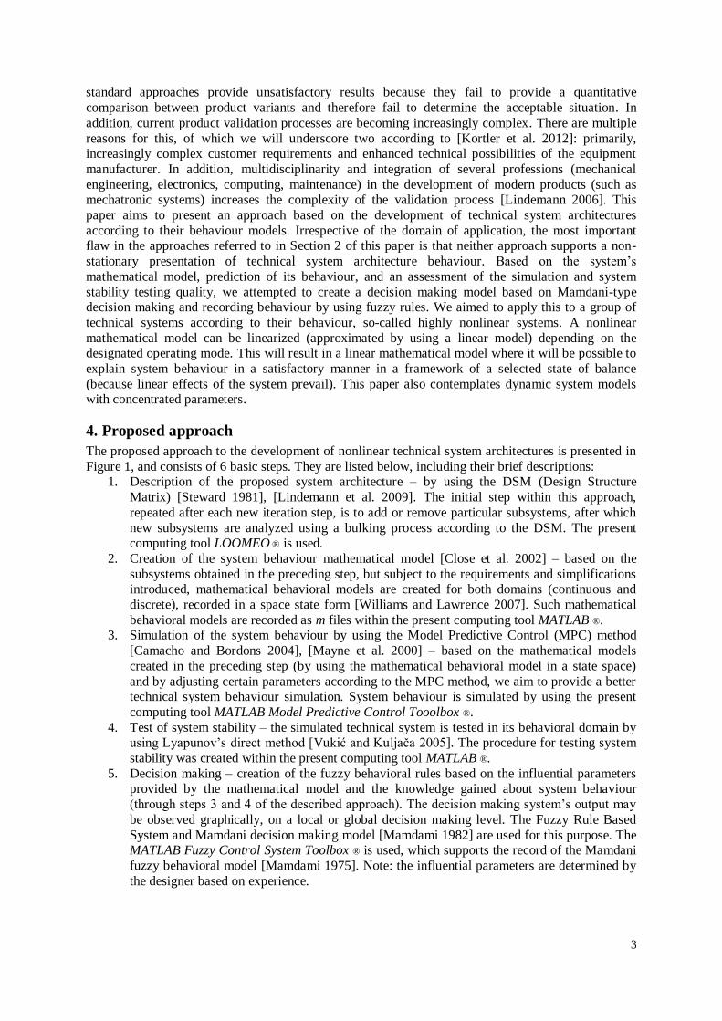
The proposed approach to the development of nonlinear technical system architectures is presented in
Figure 1, and consists of 6 basic steps. They are listed below, including their brief descriptions: 1. Description of the proposed system architecture – by using the DSM (Design Structure
Matrix) [Steward 1981], [Lindemann et al. 2009]. The initial step within this approach,
repeated after each new iteration step, is to add or remove particular subsystems, after which
new subsystems are analyzed using a bulking process according to the DSM. The present computing tool LOOMEO ® is used.
2. Creation of the system behaviour mathematical model [Close et al. 2002] – based on the
subsystems obtained in the preceding step, but subject to the requirements and simplifications introduced, mathematical behavioral models are created for both domains (continuous and
discrete), recorded in a space state form [Williams and Lawrence 2007]. Such mathematical
behavioral models are recorded as m files within the present computing tool MATLAB ®. 3. Simulation of the system behaviour by using the Model Predictive Control (MPC) method
[Camacho and Bordons 2004], [Mayne et al. 2000] – based on the mathematical models
created in the preceding step (by using the mathematical behavioral model in a state space)
and by adjusting certain parameters according to the MPC method, we aim to provide a better technical system behaviour simulation. System behaviour is simulated by using the present
computing tool MATLAB Model Predictive Control Tooolbox ®.
4. Test of system stability – the simulated technical system is tested in its behavioral domain by using Lyapunov’s direct method [Vukić and Kuljača 2005]. The procedure for testing system
stability was created within the present computing tool MATLAB ®.
5. Decision making – creation of the fuzzy behavioral rules based on the influential parameters provided by the mathematical model and the knowledge gained about system behaviour
(through steps 3 and 4 of the described approach). The decision making system’s output may
be observed graphically, on a local or global decision making level. The Fuzzy Rule Based
System and Mamdani decision making model [Mamdami 1982] are used for this purpose. The MATLAB Fuzzy Control System Toolbox ® is used, which supports the record of the Mamdani
fuzzy behavioral model [Mamdami 1975]. Note: the influential parameters are determined by
the designer based on experience.
4
6. Change of system architecture - in the case that it is impossible to conduct an effective
simulation of the technical system concerned and its instability, changes (modifications) need
to be made in the system architecture. Present system elements (subsystems) are removed or
new ones are added. This procedure is conducted when we aim to create a completely new architecture of a complex technical system or in case of changing the architecture of a
complex technical system for the purpose of improving its performance. In such case, we say
we change the behavioral rules in an existing complex technical system. As shown in Figure 1, the proposed approach for developing technical system architectures is of an
iterating nature, which means that sometimes several iterations are required (n iterations) to obtain the
desired system architecture (with a satisfactory behaviour), which would within its operating conditions also operate under uncertain conditions of the environment.
As presented in Figure 1 (for linear systems and for nonlinear systems that may be presented in a
linear form by using a linearization procedure), the MPC method is only used to ensure effective
simulation of technical system’s behaviour, while system’s stability will be tested as if the observed system were autonomous, i.e. only the mathematical model of system’s behaviour will be considered.
Figure 1. Schema of proposed approach
We also provide a description of the flow of information transferred between the respective steps within the described approach to complex system architecture development. Such transfer will be
presented between the respective steps of the proposed approach (as listed above):
Step 1 - the DSM is created on the basis of the proposed customer requirements and engineering requirements in case a new system is being developed or a present one is being
improved.
Steps 1 – 2 – the DSM provides data about the possible subsystems (modules) from the
description of the proposed complex system architecture. Based on such data about the possible subsystems, equations are set for each process (or the system as a whole) according to
the implemented mathematical modeling assumptions. In case of complex technical systems,
each process needs to be mathematically modeled separately. The process is then recorded in a state space.
Steps 2 – 3 – using the MPC method, the mathematical model just created in the preceding
step is uploaded, which the software translates into a discrete form. Subject to selecting all of
the above parameters, it is examined whether or not it is possible to conduct effective technical system simulation (after adjusting the MPC method parameters).
Steps 2 – 4 – in case of the linear system behaviour, the system (process) mathematical model
created in step 2 is used to test system stability, namely its system dynamics matrix A (from State Space form) [Mayne 2000].
Steps 2 – 5 – based on experience, the designer identifies the influential variables from the
system (process) mathematical model and MPC method to be taken into account when defining the fuzzy behavioral rules (as input variables).
DSM
MATHEMATICAL MODEL
MPC METHOD
SYSTEM STABILITY
TECHICAL SYSTEM
ARCHITECTURE
NONLINEAR TECHNICAL
SYSTEM MODEL à LINEAR
TECHNICAL SYSTEM MODEL (LINEARIZATION
METHOD)
SYSTEM BEHAVIOUR SIMULATION QUALITY
FUZZY LOGIC RULE BASED
SYSTEM
FUZZY LOGIC BEHAVIOUR
RULES
INFLUENCED VARIABLES
CUSTOMER AND ENGINEERING ASSUMPTIONS
ASSUMPTIONS
FUZZY LOGIC BEHAVIOUR RULES –
GRAPHICAL REPRESENTATION
BEHAVIORAL DOMAIN
STRUCTURE DOMAIN
1
2
3
4
5
6
WITH UNCERTAINTY CONDITIONS
LJAPUNOV DIRECT METHOD MAMDAMI BEHAVIOUR
MODELN ITERATION PROCESSES
5
Steps 4 – 5 – the information about system stability (unstable, asymptotically stable or
globally stable) is later used as an output variable when creating fuzzy behavioral rules.
Steps 5 – 6 – a system (process) found to have a satisfactory behaviour in the preceding steps
(a stable system for most input variables) and to be stable under uncertain operating conditions may be proposed for a newly developed variant of an existing technical system. In case the
system’s behaviour is not satisfactory and the system is unstable under uncertain operating
conditions, the entire procedure is repeated, starting from step 1. By altering customer or engineering requirements, new subsystems are added or existing ones are removed in the
overall technical system. Such approach is referred to as iterative because it takes several
iteration steps to come to a satisfactory solution.
5. Case study – load lifting device
An electric motor system, (load lifting device) used for lifting loads in shipyards as part of a crane was
selected as an example of a complex technical system with nonlinear behaviour. Generally, the system
consists of the following subsystems: an electric motor-driven power transmission and a load lifting drum with steel rope and a hook. During its operation, the device was exposed to atmospheric impacts
and was tested in variable operating conditions, particularly in uncertain operating conditions where
strong gusts of wind are present. The initial architecture of the lifting device is created on the basis of the customer requirements
received and the resulting engineering requirements. The lifting device’s system consists of the
following subsystems: a three-phase asynchronous electric motor, a drive and a output shaft, clutches
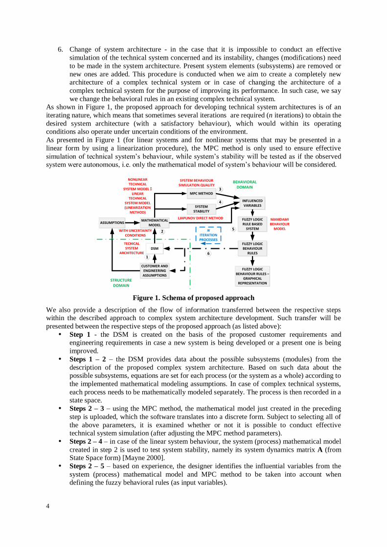
on the drive and output shafts, bearings, a single-speed power transmission, a lifting grooved drum, wire rope and a load securing hook (presented in Figure 2a).
The customer requirements are as follows:
- the device must be suitable for exterior installation, - the device must be able to operate in variable external operation conditions,
- the device must be resistant to atmospheric impacts (water, rain, snow, ice, air, gusts of wind),
- the device is intended to be installed on cranes in shipyards,
- the device must have an automated control option. The engineering requirements are as follows:
- the device is situated within the coastal belt (Croatia – EU member state),
- the device must be able to operate at high wind speeds: up to 100 km/h (Zone 3), - the device must be provided with uninterrupted electricity supply, 3x220 V, 50 Hz,
- the device must be provided with an interrupted operating mode,
- the device must be capable of lifting and lowering loads, - the electric motor driving the device must be able to operate at variable rotational speeds,
- the device is intended for lifting smaller loads of up to 10 t,
- loads should be lifted and lowered by using the hook,
- the device must be resistant to shock and vibration, - operating stability of the device must be ensured.
According to the steps of the approach described (in the preceding section), the DSM first used to
describe the proposed system architecture and an analysis resulted in possible subsystems.
Step 1
The results obtained by using the DSM [Steward 1981], [Lindemann et al. 2009] are presented in
Figure 3a. According to the subsystems given by DSM and the initial assumptions, we proceeded to create a mathematical model for the system.
Step 2
The initial assumptions that we applied to the modeling of a mathematical behavioral model for the
respective subsystems of the lifting device are as follows: - all losses in bearings, gears and clutches are neglected,
- all resistance resulting from driving the device on a railway are neglected,
- all losses in the lifting mechanism occurring during operation and standby are neglected, - the resistance taken into consideration is the resistance resulting from the effect of wind,
6
- because of the assumption that is the compact design of the three-phase asynchronous motor
and power transmission with a clutch, the driving shaft is assumed to be designed as an ideal
solid body,
- the driven shaft and steel rope are assumed to be designed as an elastic body, - the load is assumed to be of a rectangular shape and its volume is V=abc [m
3],
- loads are assumed to be directly lifted/lowered by using the drum and the steel hook,
- the device’s assumed drivetrain is drivetrain 2 [DIN 15018 1984], - the weight of the rope in relation to the weight of the hook and load is neglected because the
ratio is ,
- low vibrations are assumed in the system [Bazjanac 1974],
- the viscous damping coefficient ku of the steel rope is very small and may be neglected [Feyver 2007].
Figure 2. Load lifting device system architecture: a) initial system architecture - iteration 1, b)
final system architecture – iteration 4
Resistance resulting from wind gusts is considered as a possibility in unexpected operating conditions.
As the device is assumed to be installed on a crane within the coastal zone of the Republic of Croatia, the relevant wind speed zone is zone 3 [ISO 4302 1981]. According to the steps of the approach
described (in the preceding section), the DSM first used to create the system architecture and possible
subsystems were identified. The results obtained by using the DSM are presented in Figure 3a. The mathematical model creates differential equations of mechanism’s motion by using Lagrange’s
equations of the second type for mechanical systems in the most general form (with s degrees of
freedom of motion) [Bazjanac 1974]. After all assumptions, linearization and neglects in the mathematical model, the final form of the
technical system motion differential equations is:
(1),
(2),
(3).
Based on the given equations ((1) – (3)), a record of the load lifting device mathematical behavioral model is created in the state space [Williams and Lawrence 2007]. Also based on the given variables
and matrices in state space form, a model record and the source code is created in the existing
MATLAB ® software.
a)b)
7
Step 3
When simulating behaviour and testing system stability, influential variables presented in Table 1 are
used (in all iterations).
Legend (for variables in equations (1) – (3)):
[N/m] – torsional stiffness of output shaft
[N] – wind force
g [m/s2] – gravitational constant; g = 9.81 m/s
2
[-] – total transmission ratio
[kgm2] – dynamic moment of inertia of electromotor
[kgm2] – dynamic moment of inertia of gear 1
[kgm2] – dynamic moment of inertia of gear 2
[kgm2] – dynamic moment of inertia of grooved drum
[Ns/m] – viscous damping coefficient of output shaft
[m] – initial wire rope length
[Nm] – moment of electromotor
[kg] – total mass
[m] – grooved drum radius
[rad]– twist angle of electromotor
[rad]– twist angle of grooved drum
[rad] – twist angle of wire rope
[rad/s] – angular velocity of electromotor
[rad/s] – angular velocity of grooved drum
[rad/s2] – angular acceleration of electromotor
[rad/s2] – angular acceleration of grooved drum
[rad/s2] – angular acceleration of wire rope
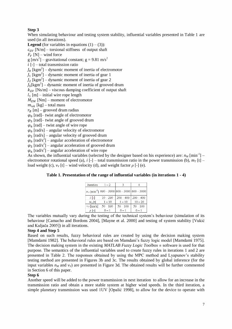
As shown, the influential variables (selected by the designer based on his experience) are: nM [min-1
] – electromotor rotational speed (a), i [-] – total transmission ratio in the power transmission (b), mT [t] –
load weight (c), vV [t] – wind velocity (d), and weight factor ρ [-] (e).
Table 1. Presentation of the range of influential variables (in iterations 1 - 4)
The variables mutually vary during the testing of the technical system’s behaviour (simulation of its
behaviour [Camacho and Bordons 2004], [Mayne et al. 2000] and testing of system stability [Vukić and Kuljača 2005]) in all iterations.
Step 4 and Step 5
Based on such results, fuzzy behavioral rules are created by using the decision making system [Mamdami 1982]. The behavioral rules are based on Mamdani’s fuzzy logic model [Mamdami 1975].
The decision making system in the existing MATLAB Fuzzy Logic Toolbox ® software is used for that
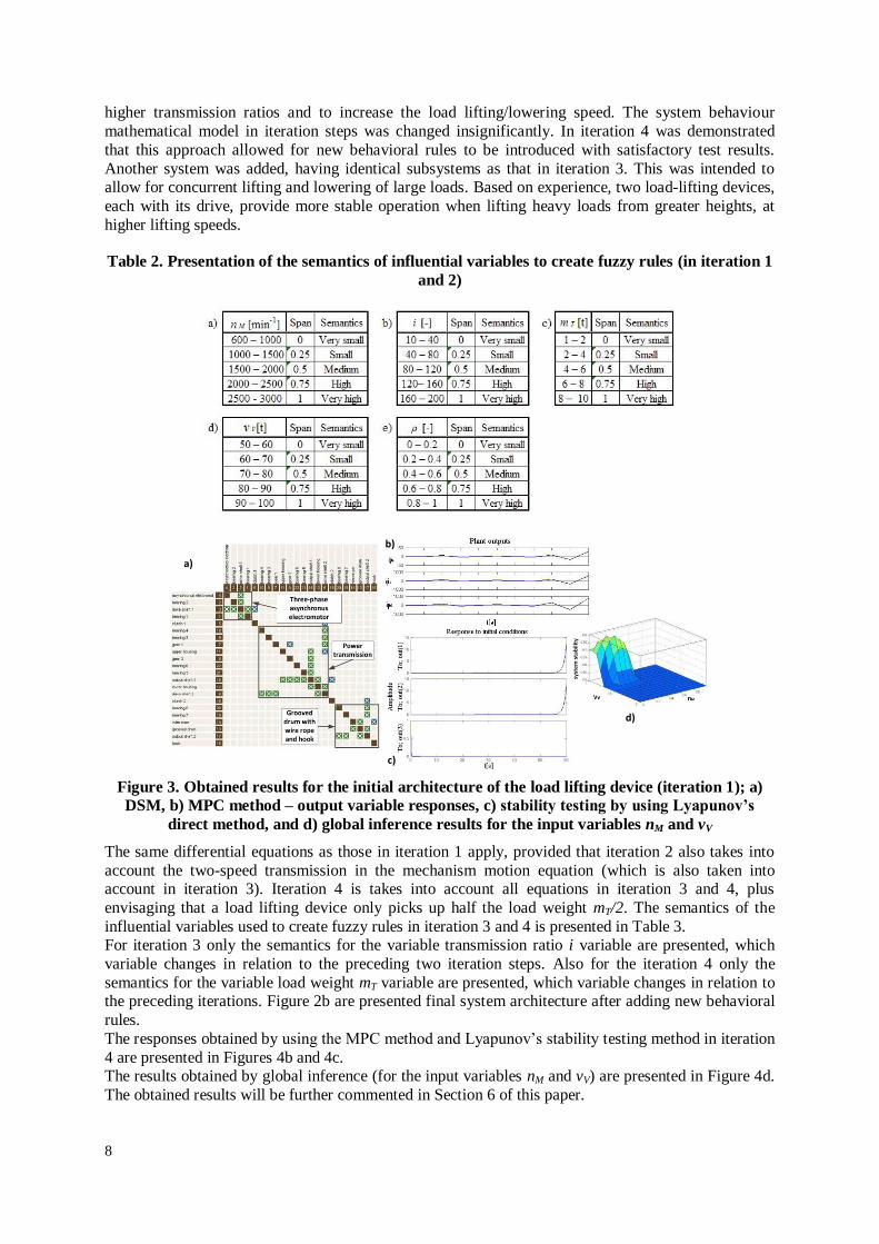
purpose. The semantics of the influential variables used to create fuzzy rules in iterations 1 and 2 are
presented in Table 2. The responses obtained by using the MPC method and Lyapunov’s stability testing method are presented in Figures 3b and 3c. The results obtained by global inference (for the
input variables nM and vV) are presented in Figure 3d. The obtained results will be further commented
in Section 6 of this paper.
Step 6
Another speed will be added to the power transmission in next iteration to allow for an increase in the
transmission ratio and obtain a more stable system at higher wind speeds. In the third iteration, a simple planetary transmission was used 1UV [Opalić 1998], to allow for the device to operate with
8
higher transmission ratios and to increase the load lifting/lowering speed. The system behaviour
mathematical model in iteration steps was changed insignificantly. In iteration 4 was demonstrated
that this approach allowed for new behavioral rules to be introduced with satisfactory test results.
Another system was added, having identical subsystems as that in iteration 3. This was intended to allow for concurrent lifting and lowering of large loads. Based on experience, two load-lifting devices,
each with its drive, provide more stable operation when lifting heavy loads from greater heights, at
higher lifting speeds.
Table 2. Presentation of the semantics of influential variables to create fuzzy rules (in iteration 1
and 2)
Figure 3. Obtained results for the initial architecture of the load lifting device (iteration 1); a)
DSM, b) MPC method – output variable responses, c) stability testing by using Lyapunov’s
direct method, and d) global inference results for the input variables nM and vV
The same differential equations as those in iteration 1 apply, provided that iteration 2 also takes into
account the two-speed transmission in the mechanism motion equation (which is also taken into account in iteration 3). Iteration 4 is takes into account all equations in iteration 3 and 4, plus
envisaging that a load lifting device only picks up half the load weight mT/2. The semantics of the
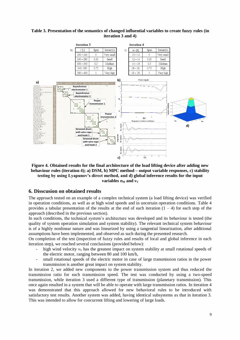
influential variables used to create fuzzy rules in iteration 3 and 4 is presented in Table 3. For iteration 3 only the semantics for the variable transmission ratio i variable are presented, which
variable changes in relation to the preceding two iteration steps. Also for the iteration 4 only the
semantics for the variable load weight mT variable are presented, which variable changes in relation to the preceding iterations. Figure 2b are presented final system architecture after adding new behavioral
rules.
The responses obtained by using the MPC method and Lyapunov’s stability testing method in iteration
4 are presented in Figures 4b and 4c. The results obtained by global inference (for the input variables nM and vV) are presented in Figure 4d.
The obtained results will be further commented in Section 6 of this paper.
a)
b)
c)
d)
9
Table 3. Presentation of the semantics of changed influential variables to create fuzzy rules (in
iteration 3 and 4)
Figure 4. Obtained results for the final architecture of the load lifting device after adding new
behaviour rules (iteration 4); a) DSM, b) MPC method – output variable responses, c) stability
testing by using Lyapunov’s direct method, and d) global inference results for the input
variables nM and vV
6. Disscusion on obtained results
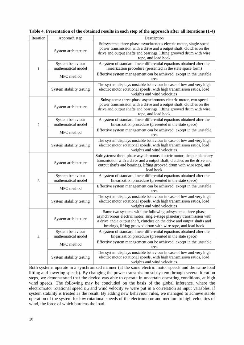
The approach tested on an example of a complex technical system (a load lifting device) was verified in operation conditions, as well as at high wind speeds and in uncertain operation conditions. Table 4
provides a tabular presentation of the results at the end of each iteration (1 – 4) for each step of the
approach (described in the previous section). In such conditions, the technical system’s architecture was developed and its behaviour is tested (the
quality of system operation simulation and system stability). The relevant technical system behaviour
is of a highly nonlinear nature and was linearized by using a tangential linearization, after additional assumptions have been implemented, and observed as such during the presented research.
On completion of the test (inspection of fuzzy rules and results of local and global inference in each
iteration step), we reached several conclusions (provided below):
- high wind velocity vV has the greatest impact on system stability at small rotational speeds of the electric motor, ranging between 80 and 100 km/h,
- small rotational speeds of the electric motor in case of large transmission ratios in the power
transmission is another great impact on system stability. In iteration 2, we added new components to the power transmission system and thus reduced the
transmission ratio for each transmission speed. The test was conducted by using a two-speed
transmission, while iteration 3 used a different type of transmission (planetary transmission). This once again resulted in a system that will be able to operate with large transmission ratios. In iteration 4
was demonstrated that this approach allowed for new behavioral rules to be introduced with
satisfactory test results. Another system was added, having identical subsystems as that in iteration 3.
This was intended to allow for concurrent lifting and lowering of large loads.
a)b)
c)
d)
10
Table 4. Presentation of the obtained results in each step of the approach after all iterations (1-4)
Iteration Approach step Description
1
System architecture
Subsystems: three-phase asynchronous electric motor, single-speed power transmission with a drive and a output shaft, clutches on the
drive and output shafts and bearings, lifting grooved drum with wire
rope, and load hook
System behaviour
mathematical model
A system of standard linear differential equations obtained after the
linearization procedure (presented in the state space form)
MPC method Effective system management can be achieved, except in the unstable
area
System stability testing The system displays unstable behaviour in case of low and very high electric motor rotational speeds, with high transmission ratios, load
weights and wind velocities
2
System architecture
Subsystems: three-phase asynchronous electric motor, two-speed power transmission with a drive and a output shaft, clutches on the
drive and output shafts and bearings, lifting grooved drum with wire
rope, and load hook
System behaviour
mathematical model
A system of standard linear differential equations obtained after the
linearization procedure (presented in the state space)
MPC method Effective system management can be achieved, except in the unstable
area
System stability testing
The system displays unstable behaviour in case of low and very high electric motor rotational speeds, with high transmission ratios, load
weights and wind velocities
3
System architecture
Subsystems: three-phase asynchronous electric motor, simple planetary
transmission with a drive and a output shaft, clutches on the drive and output shafts and bearings, lifting grooved drum with wire rope, and
load hook
System behaviour
mathematical model
A system of standard linear differential equations obtained after the
linearization procedure (presented in the state space)
MPC method Effective system management can be achieved, except in the unstable
area
System stability testing
The system displays unstable behaviour in case of low and very high electric motor rotational speeds, with high transmission ratios, load
weights and wind velocities
4
System architecture
Same two systems with the following subsystems: three-phase asynchronous electric motor, single-stage planetary transmission with
a drive and a output shaft, clutches on the drive and output shafts and
bearings, lifting grooved drum with wire rope, and load hook
System behaviour
mathematical model
A system of standard linear differential equations obtained after the
linearization procedure (presented in the state space)
MPC method Effective system management can be achieved, except in the unstable
area
System stability testing
The system displays unstable behaviour in case of low and very high electric motor rotational speeds, with high transmission ratios, load
weights and wind velocities
Both systems operate in a synchronized manner (at the same electric motor speeds and the same load
lifting and lowering speeds). By changing the power transmission subsystem through several iteration steps, we demonstrated that the device was able to operate in uncertain operating conditions, at high
wind speeds. The following may be concluded on the basis of the global inference, where the
electromotor rotational speed nM and wind velocity vV were put in a correlation as input variables, if system stability is treated as the result. By adding new behaviour rules, we managed to achieve stable
operation of the system for low rotational speeds of the electromotor and medium to high velocities of
wind, the force of which burdens the load.
11
7. Conclusion and future research
The objective of the research presented in this paper is to develop an approach modeling and
predicting the nonlinear behaviour of complex technical systems in the operating environment, based
on a presentation of the system’s dynamic behaviour and recording of such behaviour by using the rules. This approach should help develop new structures of nonlinear complex systems and improve
existing ones, by mapping in both directions, from the structural to the behavioral domain and vice
versa. It should be mentioned that the research completed was not intended to develop new modeling methods, but to provide a new approach to describing the architecture of complex technical systems. If
the existing modeling methods are used, the approach will also allow us to predict behaviour in the
operating environment.
This paper also presents a verification of the approach on an example of a highly nonlinear behaviour of technical system (example: load lifting device). It was demonstrated through several iterations in
the verification that the use of the system with new subsystems added may cause the behaviour of such
systems to change during the development of their respective architectures. The approach also allows us to include disturbance variables in the mathematical behavioral model, which cause uncertain
operating conditions. Predicting behaviour by using the MPC method allows us to develop technical
system architectures based on known behaviour of similar technical systems (by using the influential variable change trajectory). It was also verified whether or not the parameters may be adjusted to
effectively simulate the system during its operation in both real conditions and under the effect of
uncertain operating conditions. The system stability test once again determines whether or not the
nonlinear complex technical system including its subsystems operates in a stable operatig area. Only a theoretical analysis of the presented technical system’s behaviour was conducted. However,
despite the simulation results, the basic condition precedent to validating the proposed approach in a
real environment was its testing and performing experiments in real operating conditions. However, as we are currently unable to conduct such an experiment, it was not included in the research
contemplated in this paper. This is the main limitation of the presented research. It may be used as a
direction in future research.
Some limitations that could also be used as future research directions are specified below. This is primarily the duration of the procedure for simulating behaviour and testing system stability. A certain
number of variables need to be varied by putting them in correlations. Such method could be
expedited by expanding the decision making system, enabling automated rule creation and introducing a Neuro – Fuzzy Inference System.
Acknowledgements
This research is part of funded project “Models and methods of knowledge management in product
development” supported by the Ministry of Science and Technology of the Republic of Croatia.
References
…DIN 15018 – Cranes – Steel structures, Verification and analysis, Copyright Deutsches Institut Fur Normung E.V., 1984.
…ISO 4302 – Cranes – Wind load assessment, 1981.
Anggraeni, N., Maltzahn, S., Anderl, L.: “Similarity-based Concept Development for Modular Platform Systems”, In: Proceedings of ICED’13, Seoul, Korea, 2013.
Bazjanac, D.: „Technical mechanics III – dynamics“,(in Croatian), University of Zagreb, Zagreb, Hrvatska, 1974.
Camacho, E.F., Bordons, C.: “Model Predictive Control”, Springer – New York, USA, 2004.
Close, C.M., Fredrick, D.H., Newell, J.C.: „Modelling and Analysis of Dynamic Systems“, third edition, John Wiley & Sons, Inc., USA, 2002.
Diepold, K.J., Biedermann, W., Eben, K.G.M. Kortler, S., Lohmann, B., Lindemann, U.: „Combining Structural Complexity Management and Hybrid Dynamical System Modeling”, In: Proceedings of DESIGN 2010,
Dubrovnik, Croatia, vol. 2, pp. 1045 – 1054, 2010.
Diepold, K.J., Winkler, F.J., Lohmann, B.: „Systematical hybrid state modeling of complex dynamical systems: The quad - I/HS framework”, In: Mathematical and Computer Modeling of Dynamical Systems”, 16(4), pp. 347
– 371, 2010a.
12
Feyrer, K.: „Wire Rops – Tension, Endurance, Rekiability“, Springer – Verlag Berlin Heidelberg, Germany, 2007.
Hansen, C.T., Andreasen, M.M.: “Two approaches to synthesis based on the domain theory”,In Engineering Design Synthesis, (ed. A. Chakrabarti), chapter 6, Springer – Verlag London Limited, United Kingdom, pp. 93 –
108, 2002.
Hubka, V., Eder, W.E.: “Theory of Technical Systems – A Total Concept Theory for Engineering Design”, Springer – Verlag Berlin Heidelberg, Germany, 1988.
Hubka, V., Eder, W.E.: „Engineering Design: General Procedural Model of Engineering Design”, Springer – Verlag Berlin Heidelberg, Germany, 1992.
Kortler, S., Kohn, A., Lindemann, U.: „Validation of Product Properties Considering a High Variety of Complex Products“, In: Proceedings of DESIGN 2012, Dubrovnik, Croatia, vol. 3, pp. 1731 – 1740, 2012.
Kota, S., Chakabarti, A.: “A Method for Evaluation of Product Lifecycle Alternatives under Uncertainty”, In: Proceedings of ICED ’09, pp. 289-300, 2009.
Lindemann, U., „Methodische Entwicklung technischer Produkte: Methoden flexible und situationsgerecht anwenden“ Springer, Berlin, 2006.
Lindemann, U., Maurer, M., Braun, T.: “Structural Complexity Management – An Approach for the Field of Product Design”, Springer Verlag Berlin Heidelberg, Germany, 2009.
Mamdami, E.H., Assilian, S.: “An experiment in linguistic synthesis with a fuzzy logic controller”, International Journal of Man-machine Studies, 7(1), pp. 1-13, 1975.
Mamdani E.H.: “A fuzzy rule-based method of controlling dynamic processes”, IEEE Xplore, Volume: 20, pp. 1098-1103, 1982.
Mayne, D.Q., Rawlings, J.B., Rao, C.V., Scokaert, P.O.M.: „Constrained model predictive control: Stability and optimality“, Automatica 36, pp. 789-814, 2000.
Opalić, M.: „Power and motion transmission“, (in Croatian), University of Zagreb, Zagreb, Croatia, 1998.
Osman, K., Štorga, M., Stanković T., Marjanović, D.: “Behaviour Prediction Framework in System Architecture Development”, Applied Mechanics and Materials, 104(3), pp. 3-12, 2011.
Robertson, D., Ulrich, K.: “Planning for Product Platforms”, Sloan Management Review, Vol. 39, No. 4, pp. 19-31, 1998.
Simpson, T. W., Siddique, Z., Jiao, J.: “Product Platform and Product Family Design: Methods and Applications”, Springer Science+Business Media, New York, 2006.
Stark, R., Krause, F. L., Kind, C., Rothenburg, U., Müller, P., Hayka, H., Stöckert, H.: “Competing in engineering design—The role of Virtual Product Creation”, CIRP Journal of Manufacturing Science and
Technology, Vol. 3, pp. 175-184, 2010.
Steward, D. V.: “The Design Structure System: A Method for Managing the Design of Complex Systems”. IEEE Transactions on Engineering Management 28, pp. 71-74, 1981.
Strogatz, S.H.: ” Exploring complex networks”, Nature 410, pp. 268–276, 2001.
Taguchi, G.: “Taguchi on Robust Technology Development: Bringing Quality Engineering Upstream”, ASME Press, New York, 1993.
Vukić, Z., Kuljača, Lj.: “Automatic control – analysis of linear systems”, (in Croatian), Kigen, Zagreb, Croatia, 2005.
Williams II, R.L., Lawrence, D.A.: “Linear State-Space Control Systems”, John Wiley & Sons, Inc., New Jersey, USA, 2007.
Wyatt, D.F., Wyn, D.C., Jarett, J.P., Clarkson, P.J.: “Supporting product architecture design using computational design synthesis with network structure constraints”, Research in Engineering Design, 23, pp.
17-52, 2011.
M.Sc. Krešimir Osman, Dipl. Ing. M.E. Research Assistant Department of Design Chair of Design and Product Development Faculty of Mechanical Engineering and Naval Architecture, University of Zagreb, Croatia
Telephone: 385 1 6168 431 Telefax: 385 1 6168 284 Email: [email protected] URL: http://www.cadlab.fsb.hr
Related Documents