Loyola University Chicago Loyola University Chicago Loyola eCommons Loyola eCommons Master's Theses Theses and Dissertations 1940 An Apparatus For Molecular Weight Determinations An Apparatus For Molecular Weight Determinations Philip A. Lefrancois Loyola University Chicago Follow this and additional works at: https://ecommons.luc.edu/luc_theses Part of the Chemistry Commons Recommended Citation Recommended Citation Lefrancois, Philip A., "An Apparatus For Molecular Weight Determinations" (1940). Master's Theses. 259. https://ecommons.luc.edu/luc_theses/259 This Thesis is brought to you for free and open access by the Theses and Dissertations at Loyola eCommons. It has been accepted for inclusion in Master's Theses by an authorized administrator of Loyola eCommons. For more information, please contact [email protected]. This work is licensed under a Creative Commons Attribution-Noncommercial-No Derivative Works 3.0 License. Copyright © 1940 Philip A. Lefrancois

Welcome message from author
This document is posted to help you gain knowledge. Please leave a comment to let me know what you think about it! Share it to your friends and learn new things together.
Transcript

Loyola University Chicago Loyola University Chicago
Loyola eCommons Loyola eCommons
Master's Theses Theses and Dissertations
1940
An Apparatus For Molecular Weight Determinations An Apparatus For Molecular Weight Determinations
Philip A. Lefrancois Loyola University Chicago
Follow this and additional works at: https://ecommons.luc.edu/luc_theses
Part of the Chemistry Commons
Recommended Citation Recommended Citation Lefrancois, Philip A., "An Apparatus For Molecular Weight Determinations" (1940). Master's Theses. 259. https://ecommons.luc.edu/luc_theses/259
This Thesis is brought to you for free and open access by the Theses and Dissertations at Loyola eCommons. It has been accepted for inclusion in Master's Theses by an authorized administrator of Loyola eCommons. For more information, please contact [email protected].
This work is licensed under a Creative Commons Attribution-Noncommercial-No Derivative Works 3.0 License. Copyright © 1940 Philip A. Lefrancois
AN APPARATUS FOR MOLECU~Ll WEIGHT !>ETERMDTAT IONS
by Philip A. Lefrancois
A thesis submitted in partial fulfillment of the requirements for the degree of Master of Science in Loyola University of Chicago •
. rune 1940.
VITA
The author was born in San Francisco, California
on Sept. 19, 191?. He was graduated from Sacred Heart
High School of San Francisco in .Tune 1934. In May,
1938, the University of San Francisco bestowed upon
him the degree of Bachelor of Science. From September
1938 to the present he has been a graduate assistant
in the Department of Chemistry of Loyola University
of Chicago, Illinois.

ACKNOWIEDGlrnNT
The following work was undertaken at the suggestion
of Dr. Ardith P. Davis who proved to be a true friend of
the author.
The author takes sincere pleasure in gratefully
acknowledging the invaluable assistance of Dr. Ardith P.
Davis whose untiring supervision, material aid, and
valuable suggestions made the research a. pleasurable
experience.
Acknowledgment is made to the members of the Chemistry
faculty for their many assistances.

AN APPARATUS JW3. MOVWULAH WEIGHT DE1'8RUINAT IONS
INTRODUCTION
The object of this research was to design, build, and
develop technique for a molecular weight appar&tus which would
have the following advantages: (1) accuracy comparable with
the Dumas method and (2) much of the convenience of the
Victor Meyer apparatus. The work of this thesis wiil.l be
largely experimental.
It was hoped that it would be possible to measure with
high accuracy the volumes of the samples and inject them
successively into a vaporization chamber. The pressure change
caused by each injection could then be measured. The limiting
density method could be used to calculate the molecular weight.
Since the apparatus is to be used for the determinations
of vapor densities and not gas densities the methods of
determining gas densities will be omitted in the discussion •
.r.L. Gay Lussac in 1811 determined the vapor density by
the volume of a known weight of vapor. His method consisted
in injecting a known weight of sample into a graduated glass
tube 40 centimeters long filled with mercury over a reservoir.
The tube was surrounded with a hot jacket so as to vaporize
the subst8.nce. 'I'he temperature and volume of the confined
vapor were measured.
In 1868 A. W. HofmR.nn improved the method of G-ay Lussac
by substituting a measuring tube of 76 em. in length in place
of the 40 em. one. ·using 2.2. 3 liters as the mol2..r volume a
result of 157.1 was obtained as the molecular weight of carbon
tetrachloride, The result is in error by 2.15;'" as compared
to the present day value of 153.8.
In 1877 Victor MeyGrl reported his first apparatus.
1 Victor Meyer, :Ber. Deutsch. !Jh~m. Gesell., 10, 2068(1877)
The procedure consisted essentially of introducing a weighed
sample into a vessel, weighing the vessel and sample, filling
the vessel with mercury and weighing again. This was then sus
pended in a long tube containing 30 to 40 cc. of mercury l1eated
to the desired temper&.ture. U1Jon vaJ.)orization of the sample
mercury was forced out. The vessel containing the S81l1J?le and
remaining mercury W<1S weighed on cooling. 'T'he vapor density
W<ls then C8.lculated.
In the following year, 1878~ Victor Ic1eyer2 published
the ingenious method for experiment;:,_lly determining vaj,lor
2 Victor Heyer, Ber. Deutsch. Chem. Gesell., 11, 1367 (1878)
densities and hence approximate moleculcc;.r weights as we
understand the method today. A valJOrization chamber of lUO cc.
c;c l>ECi ty, cylindrical in shape, w.-:•_s connected to a gl.:.ss tube
about thrtc>e feet long with ~,-,n opening 2.t the top for the
insertion of the sample. Near the top of this was a side arm
connected so that air leaving the tube could be collected in
a eudiometer over water, The va~jorization chamber contained
asbestos on the bottom to break the fall of the sample. A
large glass jacket 1.5 feet in length surrounded the vaporiza-
tion chamber. This j <'lcket contained a substance which could be
heated high enough to readily vaporize the sample. Later the
jacket Wc1S replaced by one which extended the whole length of
the inner tube3. 'l'o obtain hi::::her temperatures for volatiliza
tion of samples, a metal container containing salt electrically
heated to the molten state completely surrounded the vaporiza
tion chamber3. 7or still higher temperatures a combustion
furnace was used3.
3 V. Meyer 12, 2204 12, 1112 12' 609
and Carl Meyer, Ber. Deutsch. Chem. Gesell.,
~i~~~l ~18?9
As compared with the J.B.A. Dumas method4, the Victor
Meyer method is much less accurate but its mc::~in .<ldvantage is
convenience and rapidity of measurement.
4 J.E.A. Dumas, Ann. de Chimie et de Physique, 33, 33? (1826
2 In the original publications of Victor Meyer and J.:B.A.
Dumas4 the following experimental results were obtained:
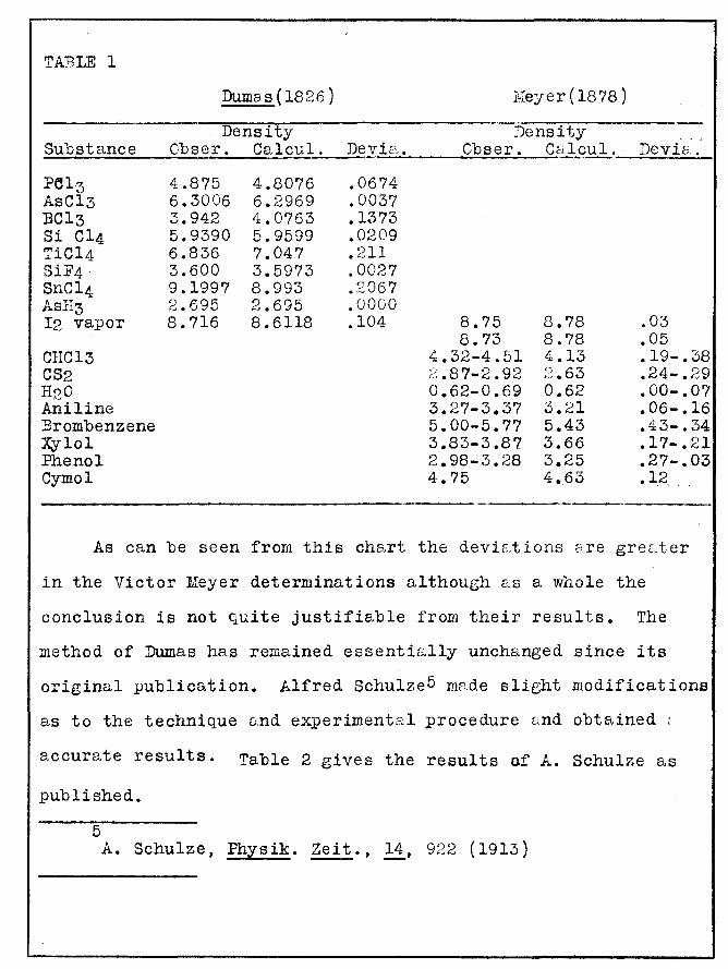
TABLE 1
Dumas(l826)
Density Substance Cbser. Calcul. Devi.;:;~. ~~~~~~~~~--~~
Pel3 AsC13 BCl3 Si Cl4 TiCl4 SiF4 SnCl4 AsH3 I2 vapor
CHC13 CS2 H00
{.,,
Aniline :Brombenzene Xylol Phenol Cymol
4.875 6. 3006 3.942 5.9390 6.836 3.600 9.1997 2.695 8.716
4.8076 6.2969 4.0763 5.9599 7.047 3.5973 8.993 2.695 8. 6118
.0674
.0037
.1373
.0209
.211
.0027
.2067
.0000
.104
Keyer(l878)
:!)ensity Obser. Calcul. Devia.
8.75 8.73
4.32-4.51 ;:2.87-2.92 0.62-0.69 3.27-3.37 5.00-5.77 3.83-3.87 2.98-3.28 4.75
8.78 8.78 4.13 :-2.63 0.62 3.21 5.43 3.66 3.25 4.63
.03
.05
.19-.38
.24-.29
.00-.07
.06-.16
.43-.34
.17-.21
.27-.03
.12
As can be seen from this chart the devistions are gre&ter
in the Victor Meyer determinations although as a whole the
conclusion is not quite justifiable from their results. The
method of Dumas has remained essenti~lly unchanged since its
original publication. Alfred Schulze5 mede slie;ht modifications
as to the technique and experimental procedure end obtained <
accurate results. Table 2 gives the results of A. Schulze as
published.
5 A. Schulze, Physik. Zeit., 14, 922 (1913)

TABLE 2
Experimentc;.l Liolecular ''::7t. Per Cen,t Substance ________ -=M~o~l~e~c~u~l~a~r~W~t~.--~(~a~t~o~·~w~t~-_;1~9~3~8) ____ -=Error
Ethyl Ether
cs2 (so 0 c.) Acetone Benzene Chloroform CClt1 c2u5ou (99.8%) CH30H Ethylacetate Hexane C2H4Cl2 lTi trobenzene
74.15 74.16 74.03 77.84 58.22 78.01
120.39 154.31 45.97 32.17 88.16 86.15 99.07
123.70
74.11 a.ver.
74.12
76.13 58.08 78.11
119.39 153.84 46.07 32.04 88.10 86.17 98.96
123.11
0.014
:~ .24 0.24 0.13 0.84 0.31 0.22 0.41 0.07 0.02 0.11 0.48
Average 0 •. 42% .
As a classic example of the use of the Dumas method as to
reproducibility, Baxter and Starkweather6 weighed five samples
of gas in two different two liter globes with a deviation of
-5 3 x 10 grams.
6 G.P. Baxter a.nd H.W. Starkweather, Proc. 1;ratl. Acad. Sci. 1;.s., 12, 703 (1926) - - -- -
Since the simple gn.s le,w is used to calcule,te the molecular
weights the results are usually too le.rge. The introduction
of the method of limiting density by Berthelot? was the most
important improvement to the calculation of more exact values
of the molecular weights.
7 D. Berthelot, Compt. Rend. 129, 954 (1898)
Journ. Phys. {3J 8, 263 (1899) Zeit. E1ektro., 34, 621 (1904)
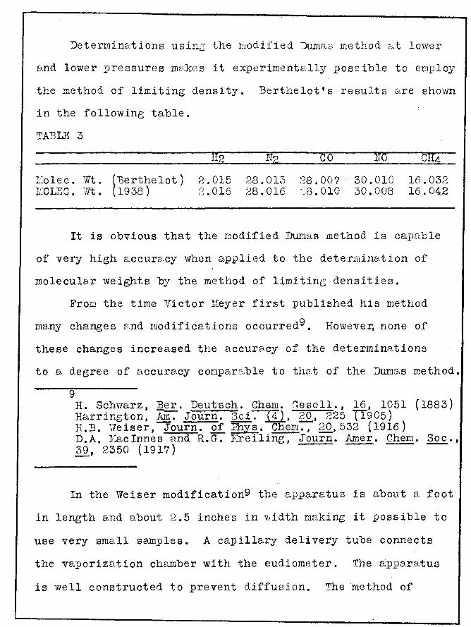
"Determinations usinc the modified ::Almaro method ,,,t lower
and lower pressures m~3kes it experimentally possible to employ
the method of limiting density. :Berthelot's results a.re shovm
in the following table.
TABL?~ 3
I.lolec. Wt. 1iOLEC. Wt.
(Berthelot) (1938)
2.015 ;-~.016
28.013 28.016
co 28.007 ;s. 010
NO
30.010 30.008
16.032 16.04.2
It is obvious that the modified Dur:w.s method is capable
of very high accure..cy when applied to the determinetion of
molecular weights by the method of limiting densities.
From the time Victor Meyer first published his method
many changes c;nd modifications occurredg. However, none of
these changes increased the accuracy of the determinations
to a degree of accura.cy compar2.ble to that of the DumB.s method.
9 H. Schwarz, @. Deutsch. Chem. fTesell., 16, 1051 (1883) Harrington, run. Journ. Sci~, 20, 225 Tf905) H.B. Weiser, Journ. of Phys. Chem., 20,532 (1916) D.A. ]::acinnes and R.G. F..reiling, Journ. Amer. Chem. Soc., 39, 2.350 (1917) -- - -
In the Weiser modification9 the apparatus is about a foot
in length and about 2.5 inches in width m2.king it possible to
use very smEtll sell1ples. A capilla.ry delivery tube connects
the vaporization chamber with the eudiometer. The appctratus
is well constructed to prevent diffusion. The method of

introducing the sample by allowing a. sample vic:."l to drop into
the chamber is not the most desireable as was pointed out by
Mac Innes and Kreiling9. Using pure chemicals (redried and
redistilled), removing vapor e:dter each determination, making
the correction for water vapor as described by EvanslO, the
following results were re_ported using samples varying from
0.0490 to 0.1748 grams.
10 P.N. ~vans, J. Amer. Chern. Soc., 35, 958 (1913)
TABLE 4
Substance
:Benzene
Chloroform
Methyl Alcohol
Ether
Ethyl Acetate
E.xp. 1~olec. Weight
80.4 79.2 80.6 79.2
118.3 117.3 117.1 32.1 32.3 32.05 31.7 31.6 73.4 73.2 7;""~. 6 87.3 87.3 86.2 87.9
!\ir.olec. Wt. ( 1938)
78.11
119.39
32.04
74.12
88.10
Per Cent Error
2.94 1.41 3.20 1.41 0.92 1. 76 1.92 0.18 0.81 0.03 1.06 1.37 0.95 1.21 2. 02 0.91 0.91 2.16 0. ~~3
Average 1.34%.
:Mac Innes and I\.reiling9 modified the Victor Meyer method
by seE,ling the se...rnple in a glass bulb which was put inside the

the vaporization chamber and broken when the temperature was
constant. This was a decided improvement for in the older
methods the air was chilled by the bulb being dropped in from
the outside. A gas buret with a leveling bulb was employed
instead of the usual eudiometer tube as the air did not escape
quickly enough through the capillary connection from the vapor-
ization chamber. · Also by use of the leveling bulb a slight
suction could be employed before the immediate vaporization of
the sample which was advantageous. Samples varying from 0.0486
to 0.2059 grams were used and corrections for air displacement:
of weights, water vaporlO , 0
and barometric pressure to Q C.
were made. The -next table gives their results showing the
molecular weights as obtained from the Gas Law and from
Berthelot's equation 'M.W •• mRT' [ 1-PiT'
9PTc (1 - 6TTX2 ~
128PcT !J where T' and V' refer to the temperature and volume of the
displaced air, and T is the temperature at which vaporization
occurs.
Table 5
Substance
Bromine
Molecular Weight Gas Law Berthelot 1938
163.7 164.4 163.0
{;166.9) 163.8 164.0 163.0
159.9 160.6 159.3
(163.()) 160.0 160.3 159.3
159.83
continued on next page
Per Cent Error Gas Law Berthelot
2.44 2.9 2.0
(4.4) 2.5 2.6 2.0
0.66 0.44 0.31
(2.00) 0.13 0.31 0.31

TABLE 5 continued
Molecular Weight Per Cent Err.o.r Substance Gas Law Berthelot 1938 Gas Law Berthelot
Ethyl Alcohol 46.3 45.9 46.07 0.43 0.43 46.8 46.4 1.52 0.65 46.9 46.4 1.73 0.65 46.7 46.3 1.30 0.43 46.6 46.1 1.08 o.oo 46.4 45.9 0.65 0.43 46.7 46.2 1.30 0.22
Ether 75.72 74.2 74.12 2.16 0.14 75.26 73.8 1.54 0.41 74.9 (73.5) 1.08 0.81 75.7 74.2 2.16 0.14
Average 1.88% 0.44%
From the above results we see the molecular weight calculated
from the gas law is one or two units higher than the accepted
value while that from Berthelot's equation varies by only a
few tenths of a unit.
The first fundamental uhange in the method of Victor Meyer
was introduced by Bleier and Kohnll and modified by J.S. Lumsden
11 The apparatus instead of being constant p~essure as in the
11 0. Bleier and L. Kohn, Chern. Centr., 2, 737 J.S. Lumsden, Journ. of Chern. Soc., 83, 342
( 1899) (1903)
Victor Meyer method was changed to constant volume and
consequently pressure changes were observed inste2.d of volume
changes. A bulb of 100 cc. served as the vaporization chamber
and was connected.to a mercury column and a leveling device to
maintain constant volume. The sample was in a bulb inside the
apparatus and was allowed to fall on a small amount of fusible
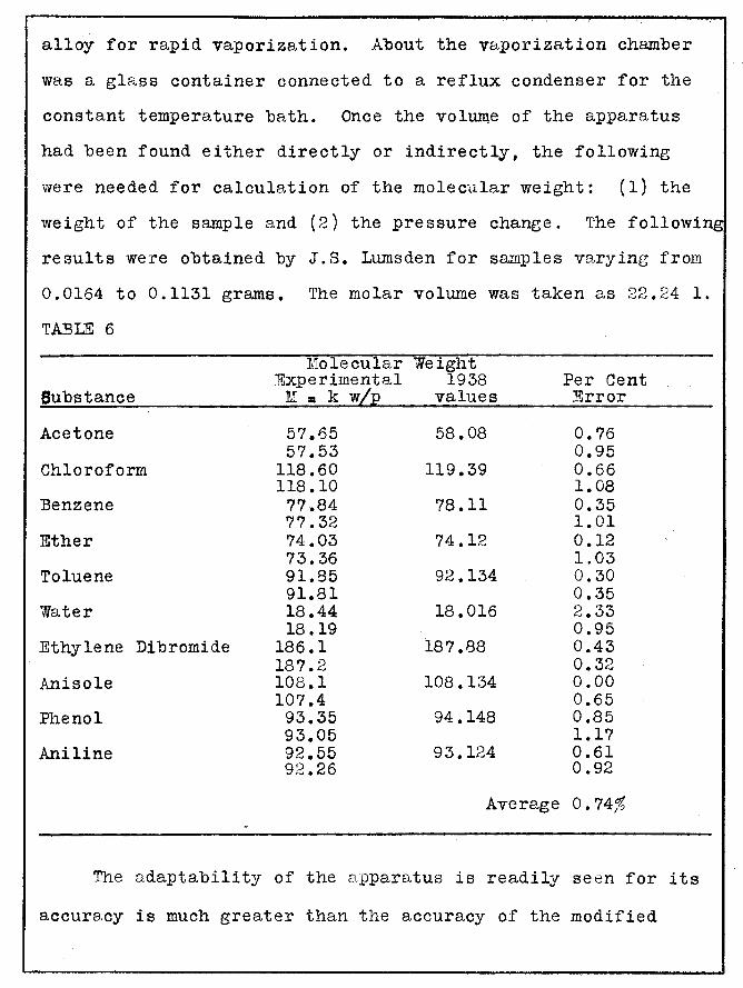
alloy for rapid vaporization. About the vaporization chamber
was a glass container connected to a reflux condenser for the
constant temperature bath. Once the volume of the apparatus
had been found either directly or indirectly, the following
were needed for calculation of the molecular weight: (1) the
weight of the sample and (2) the pressure change. The followin
results were obtained by J.S. Lumsden for samples varying from
0.0164 to 0.1131 grams. The molar volume was taken as 22.24 1.
TABLE 6
M:olecular Weight "Experimental 1938 Per Cent
Substance M = k w/p values Error
Acetone 57.65 58.08 0.76 57.53 0.95
Chloroform 118.60 119.39 0.66 118.10 1.08
Benzene 77.84 78.11 0.35 77.32 1.01
Ether 74.03 74.12 0.12 73.36 1.03
Toluene 91.85 92.134 0.30 91.81 0.35
Water 18.44 18.016 2.33 18.19 0.95
Ethylene Dibromide 186.1 187.88 0.43 187.2 0.32
Anisole 108.1 108.134 0.00 107.4 0.65
Phenol 93.35 94.148 0.85 93.05 1.17
Aniline 92.55 93.124 0.61 92.26 0.92
Average o. 74%
The adaptability of the apparatus is readily seen for its
accuracy is much greater than the accuracy of the modified

Victor Meyer methods previously mentioned. The rapidity of
measurement, simplicity of calculation, inexpensiveness of
apparatus makes it readily desireable for obtaining approximate
molecular weights. However, there are some disadvantages, :
namely, the possibility of diffusion of the sample from the
vaporization chamber, the possibility of superheating the
constant temperature bath by direct heating~ and lastly, the
lack of refinements in the pressure measurements.
The average error of Lumsden's results was 0.74% as comparee
to 1.34% for Weiser's results and 1.88%' for Mas Innes and
Kreiling. This shows an improved accuracy over the original
method.
One of the best features of the apparatus of Lumsden is its
applicability to measurements at diminished pressure and hence
the method of limiting density can be used whereas it cannot
be used with the modified Victor Meyer methods. Therefore in
this research an apparatus was designed to
(1) increase the facility of sample injection
(2) prevent diffusion of the vapor
(3) maintain a constant temperature
( 4) maintain a constant volume.
With an apparatus operating at a constant volume, measurements
at low pressures may be made in order to use the method of
limiting density.

f. Au, f fr , ..•. ~;..,, 1 "~ ..... " ,,,,,l
J)
'\ L, .I
/
T
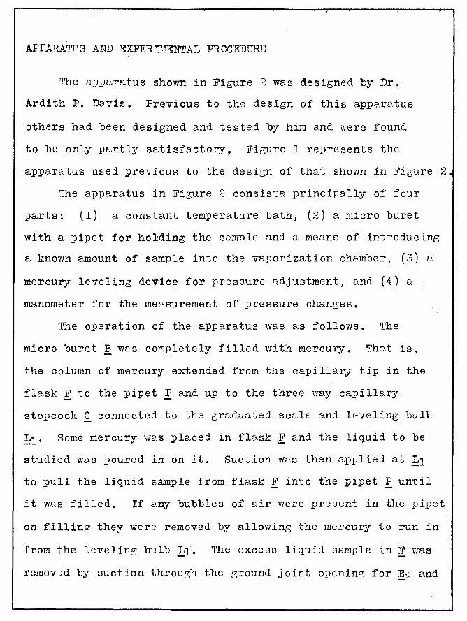
APPA"RATT,.S AND EXPERTI:ffiNTAL PROCT!iDffi1.:E
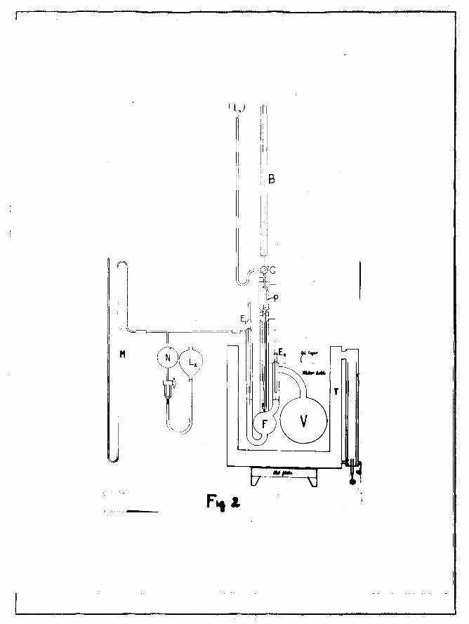
"'he apparatus shown in Figure 2 was designed by Dr.
Ardith P. Davis. Previous to the design of this apparatus
others had been designed and tested by him and were found
to be only partly satisfactory, Figure l represents the
apparatus used previous to the desien of that shown in Figure 2.
The apparatus in Figure 2 consista principally of four
parts: ( 1) a constant temperature bath, (2) a micro buret
with a pipet for holding the sample and a means of introducing
a known amount of sample into the vaporization chamber, (3) a
mercury leveling device for pressure adjustment, and (4) a .
manometer for the measurement of pressure changes.
The operation of the apparatus was a,s follows. The
micro buret B was completely filled with mercury. 'That is,
the column of mercury extended from the capillary tip in the
flask F to the pipet P and up to the three way capillary
stopcock C connected to the graduated scale and leveling bulb
L1 • Some mercury was placed in flask F and the liquid to be
studied was poured in on it. Suction was then applied at L1
to pull the liquid sample from flask F into the pipet P until
it was filled. If any bubbles of air were present in the pipet
on filling they were removed by allowing the mercury to run in
from the leveling bulb L1. The excess liquid sample in F was
remov:cd by suction through the ground joint opening for E0 and -··

more mercury added until upon putting in electrodes £1 and E2
the light glowed ( 2 vvatt light connected to a small battery).
Tap water was circulated about the buret and pipet inside the
apparatus to prevent vaporization of the liquid sample until
injected into the flask F.
'Boiling water was added to the thermoba.th. The thermo-
jacket T, constructed of galvanized tin and a copper condenser,
was brought to the tempera,ture of steam by a hot _plate. The
va_pors of the excess sa.mple in arm E2and fl;:.,sk V were removed
by suction; the pressure adjustment flask N was a.lmost em}?tied
of its mercury; and the electrodes were sealed into place
with a thin cor~ting of sugar. Eore boiling water WB,s added
until the ground joint of ;§;'? was completely immersed. A layer
of paraffin oil was plc:~ced over the hot w£tter to prevent ra}Jid
va.i!orization of the water. With the aid of a General Electric
immersion heater and an efficient electric stirrer the thermo-
bath ws~s ra};Jidly brought to a constEmt temperD,ture. Celotex
insula.ting board was .t;le.ced over the top of the thermobath.
iTo temperature differential was observale upon moving a thermo':"'
meter graduated to tenths of a degree throughout different parts
of the bath.
It is to be noted that the length of the plc:.:.tinrun leE,.d in
:Til was much lancer than that of E2 because the ELdj uBtments of
constant volume were made in the c:.,rm Therefore, it was
very essential tha.t the electrode E? be inserted in the same

position each time to keep the Cfl.librated volume the SE',Jl'le.
The platinum leads were ettached to tungsten wire see-led througl:
the pyrex gla.ss.
The mercury level in the arm E2 vv&.s controlled by the ~·
pressure adjustment flc,.sk U and leveline; bulb L<J. .1.\:n. incres.se - _, ..... ~
of mercury in flask n caused a pressure increase and a conse
c;.uent incre1Jse of the mercury height in the arm E.-,. By use
of the slow and fast bores of the stopcock below flask N a
rapid or fine adjustment could te mB.de to the constant volume
point. The constant volume point wc:,_.s that point at which the
mercury surface made contc=1 ct with the platinum wire in the arm
E9 • This was indicated by the lighting of the small bulb.
To make the final adjustment to the constant volume point the
mercury surface wc-:.s &lweys r<:tised to the contc.;.ct point c=:.nd
never lo'\vered to the cont&.ct bre::: d point. When the manometer
readings were constant upon repeated adjustments with the
leveling arrangement N and the light, a sample was introduced.
The mercury level in the buret B wr,s read then opened to the
pipet by means of the three way stopcock and the mercury a.llowed
to force out a desired amount of sample.
The sample ws.s expelled into the hot mercury in flB.sk F
causing en immediate vaporization. The resulting incree.se of
_pressure in V forced the mercury lev.;l in the arm E~ to fall
8nd the light contc:1.ct broken. The method outlined a.uove we.s
used to bring the mercury back to the constc:mt volume point.
J.v
r---------------------------------~------~----~
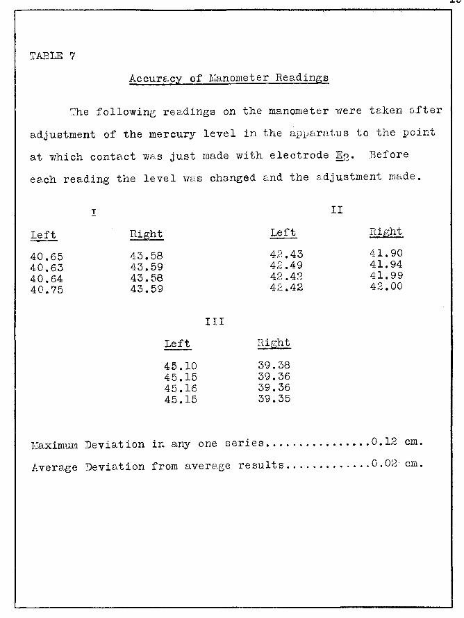
TA:BLE 7
Accur&"cy of I1~anometer Readings
'?he following re2.dings on the manometer were t&.ken a.fter
adjustment of the mercury level in the a.Pl)aratus to the point
at which contact w:.:<.s just made with electrode ~. Before
ee.ch reading the leve 1 was changed e.nd the 8.dj ustment made.
Left
40.65 40.63 40.64 40.75
I
43.58 43.59 43.58 43.59
Left
45.10 45.15 45.16 45.15
III
Left
42.43 42.49 42.42 42.42
n· ht ~~.lg
39.38 39.36 39.36 39.35
II
rlight
41.90 41.94 41.99 42.00
Eaximum Deviation in any one series •............••• 0.12 em.
Average Deviation from averc.e;e results ............. 0.02 em.

The manometer readings were t&,ken, the buret was read, e..nd the
tempere,ture of the thermobe.th ta,ken on the calibrc.,.ted thermc
meter. Other samples were injected until the leveling bulb
L2 was almost empty.
ASSEl;IBLH-:-G OF TIIE APPJu~TUS
A mercury vapor diffusion pump was used to test the glass
seals for leaks. Pressure we,s found with a l.~cCloud gage.
The jacket surroundine; the tube contcdnine; the buret capill.s,ry
and circule,ting water was eva,cuc:,ted to less than 0.002 mm. to
lower the heat tnmsference fron the thermobD,th to the inner
capillsry conte.ining the vol2tile liquid sample. H. Gregory
and C.T. Archerl2 found the heat conductivity of c:dr belov;
one millimeter pressure is very sm<;,,ll as cor.1pared to that at
760 mm.
.L6
12 H. Gregory and C. T. Archer, Phil. Mag., ffil:., 593(1926)
The next and most difficult t8,sk was to assemcle the
1.5 meter long micro buret into the apparatus. The micro
buret was not calibrF,ted by the c:utthor since the calibration
was available and the accuracy of the apparatus was still
unknown. 'f'he calibration is given on the following lJage.
The c;,verFge VEtlue of 0. 0?60 cubic centimeters lJer centimeter
reading on the buret was the value used in the celcul&tions.
the buret reu,dings were taken from centimeter graph pe..per
shellacked to the buret which was made from a uniform l)iece

TABLE 8
0 TemperB.ture 25 C.
'llt. Buret Wt.
of :Bottle plus of mercury
Readings vlith drawn from Buret
2.80 35.9321 6.10 34.7598
12.70 32.4145 17.60 30.7416 22.30 29.0955 29.75 26.4556 35.10 24.5950 37.95 23.5803 43.80 :21.5423 46.90 20.4251
Vo1./cm. = Weight Diff. Read. Diff. X 13b3
Difference of "1To1./cm.
Weight
1.17~?3 0.0262 1.1723 0.0262 ~;.3453 0.0263 1.6729 0.0252 l. 6461 0.0259 2.6399 0.0262 1.8606 0.0257 l. 0147 0.0262 2. 0380 0.0258 1.1172 0.0~~66
Avera.ge 0.0260 cc.
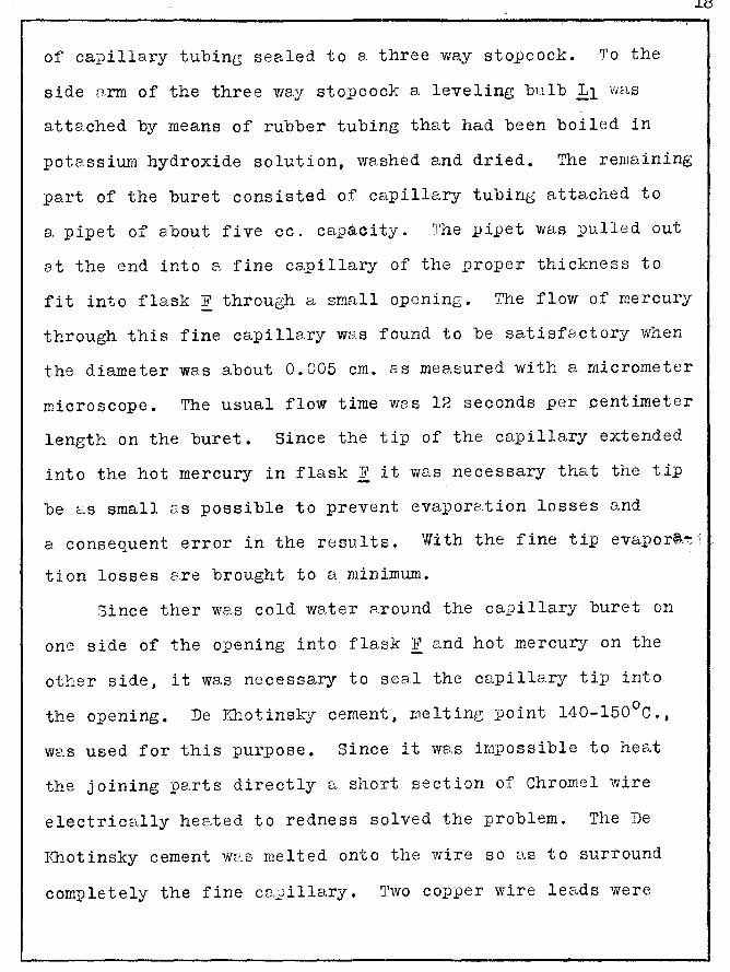
of ca:pilla.ry tubing sealed to a three way stopcock. To the
side arm of the three way stopcock a leveling btilb L1 v1as
attached by means of rubber tubing that had been boiled in
pot8.ssium hydroxide solution, washed and dried. The remaining
part of the buret consisted o:f capillary tubing attached to
a. pipet of about five cc. capacity. The pipet was pulled out
at the end into a fine capillary of the proper thickness to
fit into flask F through a small opening. The flow of mercury
through this fine capillary WEJ.S found to be satisfa.ctory when
the diameter was about 0.005 em. as measured with a micrometer
microscope. The usual flow time was 12 seconds per .centimeter
length on the buret. Since the tip of the capillary extended
into the hot mercury in flask F it was necessary that the tip
be as small as possible to prevent evaporetion losses and
18
a consequent error in the results. With the fine tip evapor~~;
tion losses are brought to a minimum.
Since ther was cold water e.round the capillary buret on
one side of the opening into flask F and hot mercury on the
other side, it was necessary to sea.l the capillary til) into
the opening. De J.~otinsky cement, melting point 140-150°C.,
w2.s used for this purpose. Since it w8.s impossible to hea.t
the joining pe.rts directly a short section of Chromel wire
electrically heated to redness solved the problem. The De
Illiotinsky cement wc:.s melted onto the wire so c::1.s to surround
completely the fine cB.)illary. Two copper wire leads were
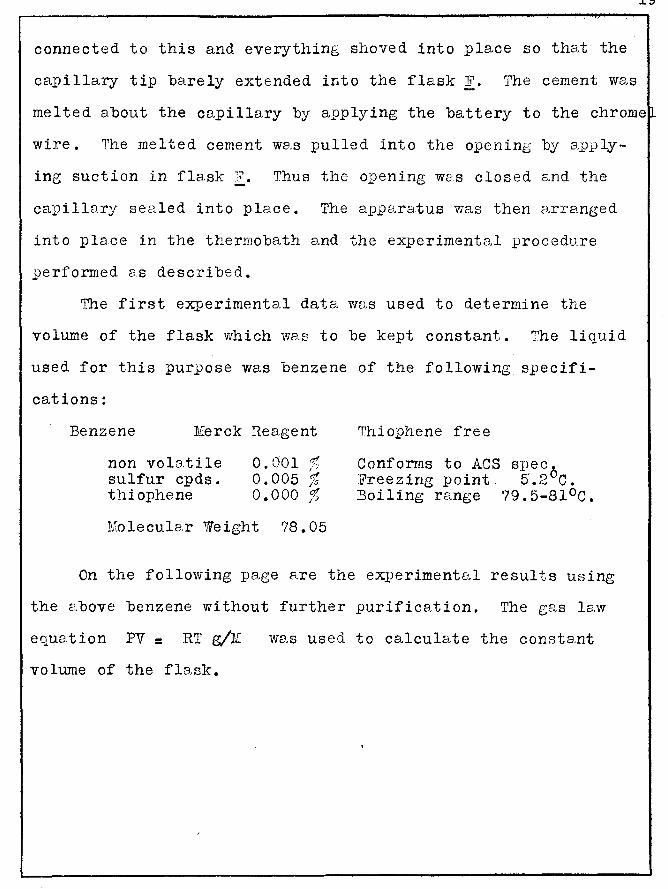
connected to this and everything shoved into place so that the
capillary tip barely extended into the flask F. The cement we.s
melted about the ce.pillary by applying the battery to the chrome~
wire. The mel ted cement wa,s pulled into the openine by ap.LJly-
ing suction in flask :? • Thus the opening W8.s closed and the
capillary sealed into place. The a11paratus was then CJ,rranged
into place in the thermobath and the experimental procedure
performed as described.
The first experimenta.l data was used to determine the
volume of the flask which was to be kept constant. The liquid
used for this purpose was benzene of the following specifi-
cations:
Benzene M:erck Reagent
non volatile sulfur cpds. thiophene
0.001 ~ i'"
0.005 % o.ooo %
:M:olecula.r Weight 78.05
Thiophene free
Conforms to ACS spec0 Freezing point. 5.2 C.
Boiling range 79.5-81°C.
On the following page are the ex1)erimental results using
the e,bove benzene without further purification. The gas law
equation PV = RT g/lt..
volume of the flask.
was used to calculate the constant
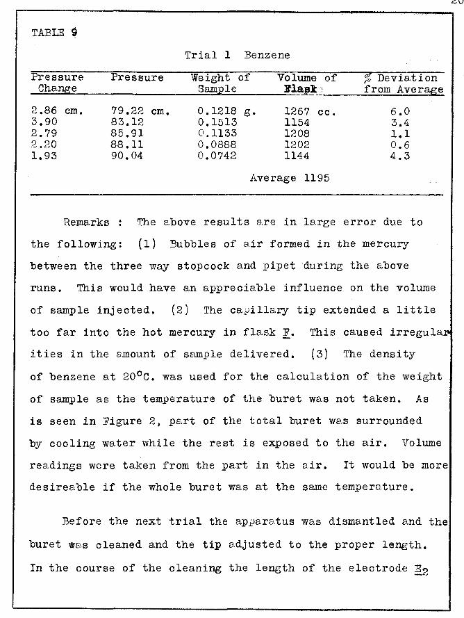
TABLE ~
Trial 1 Benzene
Pressure Pressure Weight of Volume of % Deviation ___.C_h_a_n...,g._e _________ _..;,;;.S.;.;am;;;;;;a;p..;;;l..;;.e ___ __;;:B'::..=:.:laJS..!~;---..;;f_r...;o;...m__;;A.;;..v;...e;;..;r;...a..;Jg-.e.;;..
2.86 em. 79.22 em. 0.1218 g. 1267 cc. 3.90 83.12 0.1513 1154 2.79 85.91 0.1133 1208 2.20 88.11 0.0888 1202 1.93 90.04 0.0742 1144
Average 1195
6.0 3.4 1.1 0.6 4.3
Remarks : The above results are in large error due to
the following: (1) Bubbles of air formed in the mercury
between the three way stopcock and pipet during the above
runs. This would have an appreciable influence on the volume
of sample injected. (2) The ca~illary tip extended a little
too far into the hot mercury in flask F. This caused irregula
ities in the amount of sample delivered. (3) The density
of benzene at 20°C. was used for the calculation of the weight
of sample as the temperature of the buret was not taken. As
is seen in Figure 2, pa.rt of the total buret was surrounded
by cooling wa..ter while the rest is exposed to the air. Volume
readings were taken from the part in the air. It would be more
desireable if the whole buret was at the same temperature.
Before the next trial the apparatus was dismantled and the
buret was cleaned and the tip adjusted to the proper length.
In the course of the cleaning the length of the electrode E2

was changed which of course changed the volume in the flask v. The tempera.ture of the calibrated part of the buret was taken
for each reading and the corresponding density of the benzene
obtained from the International Critical Tables.
TABLE 10
Pressure Pressure Change
6.65 em. 81.02 em 8.14 89.16 5.97 95.13 7.81 102.94 6.74 109.68
Total 28.57 109.68
Trial 2 Benzene
Weight of Sample
0.2599 g. 0.3164 0.~2317 0.3085 Q.2664
Volume of Flask
1165 cc. 1158 1157 1177 1178
Average 1167
1.1171 1165
% Deviation from Average
0.17 0.77 0.86 0.86 0.94
Average 0.72%
0.17
In order to use another liquid sample the buret was
cleaned by blowing air through it for two hours. The next
liquid was Baker and Adamson's reagent grade carbon tetra-
chloride. Its molecular weight was 153.8
TABLE 11 Trial 3 Carbon Tetrachloride
Pressure Pressure Weight of Constant Molec Wt. %f)ev. Chan~e Sam~le Volume Calculation
9.05 em. 96.06 em 0.6978 g. ll67(trial 2) 153.6 0.13
from Ave 8.06 81.43 0.6208 1164 0.26 7.93 89.36 0.6043 1152 1.28 7.91 80.39 0.6164 1178 0.94 8.43 88.82 0.6657 1194 2.32 8.14 90.02 0.6160 1145 1.89 6.46 96.48 0.4986 1167 o.oo
Average 1167 Averae:.e 1 11'1,

Due to an experimental difficulty after the first run
in Table 11, the electrode E2 had to be clea.ned. Hence the
grouping of the remaining results. From the average result
obtained with carbon tetrachloride and that with benzene appa
rently the volume was not changed.
At this point it was decided to suspend any further work
on this apparatus for the following reasons:
(1) The apparatus was not convenient. The greatest difficulty
encountered was in assembling the micro buret into the
apparatus without breaking the tip.
(2) The great possibility of changing the length of the
platinum lead of E2 when the electrode is removed from the
apparatus is not to be desired.
The apparatus however had certain marked advantages:
(1) 1bere was no pos~le diffusion of the vapor whereas in
all the apparatus, with the exception of the Dumas method,
reported in the litere.1ture survey there was a possibility
of dtiffusion.
(2) The actual recording of the readings was very simple
and rapid.
(3) The method of introduction of the sample through the
capillary tip of the micro buret proved to be very satis
factory.
The apparatus just described will be referred to as
apparatus number 1.

APPARATUS HUMBER 2
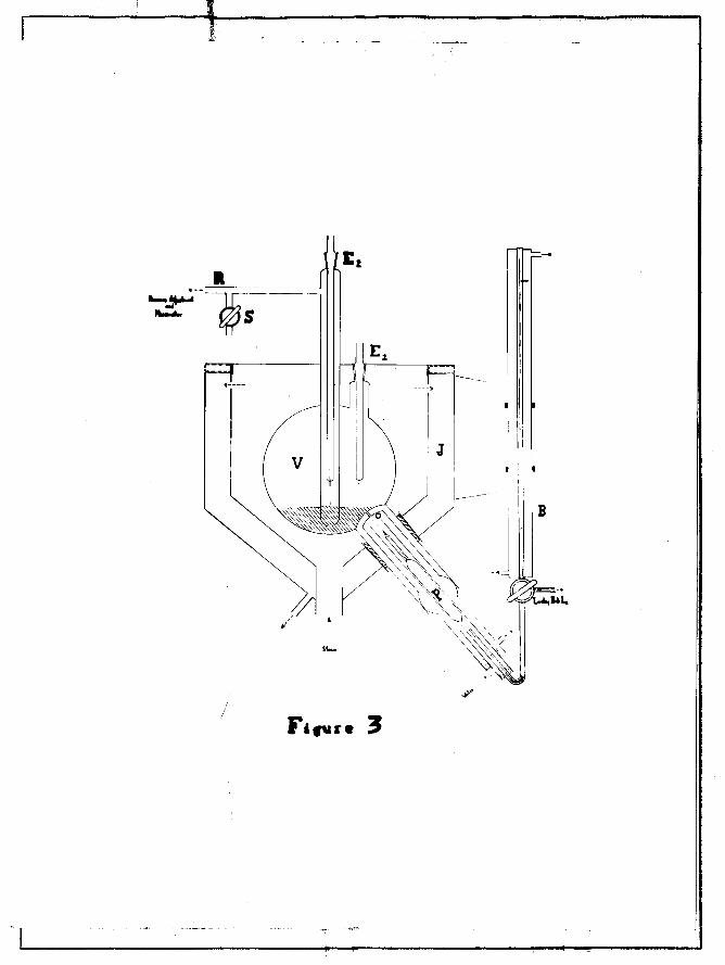
The apparatus was designed by Dr. A. P. Davis and is
shown in Figure 3. Essentially the method consisted of the
same general principles as outlined for the previous apparatus.
B was a newly calibrated micro buret of 40 em. length
consisting of two parts of thermometer tubing separated by
12 em. of 1 mm. bore capillary tubing. The buret was enclosed
in a glass jacket. The three way capillary stopcock connected
the micro buret with the leveling bulb Ll and the pi)et which
was drawn out to a fine capillary. Tap water of known temp
erature circulated about the pipet and into the water jacket
of the buret. !2 was the electrode used for constant volume.
V was the vapor chamber made from a one liter flask. The
side arm R was connected to the same pressure measuring
device used with the previously described apparatus. A gal
vanized iron steam jacketed thermobath J was used for
constant temperature. A continual flow of steam entered at
the bottom, circulated about the flask and into the outer
jacket. The temperature remained very constant throughout.
The operation was as follows. Suction was applied at the
top of the buret and at the.leveling bulb 11. which contained
about 10 cc. of mercury. Mercury was allowed to flow into the
stopcock when the pressure was about 0.001 mm. This was
performed to remove any air trapped about the three way
stopcock. The buret and pipet were filled completely with
mercury. The liquid sample { about 5 cc.) wr:.s introduced into
the flask V on top of the mercury level which covered the
capillary opening. By tilting the whole apparatus the liquid
sample was made to cover the capillary opening. Suction was
then applied at L1 to fill the pipet with the sample. The
buret and pipet were kept at the same temperature by circu
lating tap water. The apparatus was set back into place and
the mercury in the flask Y again covered the ca:pillary opening
By bringing the apparc:-:.tus to the temperature of steam the
excess liquid sample in flask V was volatilized and removed
by suction through the opening at E1. The electrodes were
sealed with a thin coating of sugar and the apparatus allowed
to come to constan temperature. The pressure adjustment sys
tem was now manipulated so as to make the mercury in flask
V and arm E2 to come into contact with the platinum electrode
of E2. The platinum electrode of z1 was necessarily longer
than that of ~~· The same methods and precautions were
followed a.s described fot the first apparatus on page 14.
A cathetometer was utilized for reading the manometer.
71hen the cathetometer reading was constant a sample was
injected {see page 32). Air pressure was required to force
the mercury level in the micro buret to fall so as to
introduce a sample. Readings on the micro buret were taken
on the thermometer tubing. The increase of pressure in
flask V due to the vaporization of the sample caused the

mercury in the arm!~ to rise. The constant volume point
was then adjusted and the cathetometer reading taken.
The apparatus was designed so that repeated samples could
be injected until the pressure adjustment could no longer
be made. If more sample remained in the pipet, the electrode
E1, not E~, could then be removed to allow the escape of the
vapors in flask V. Instead of removing E1 suction could be
applied at the stopcock S connected to R and the apparatus
tilted until the arm E~ was open to the flask V. -~-·
Heasurernents at lower pressures could be made with
facility. The apparatus could be tilted to allow V to be
open to the arm ~ and suction applied at S to the desired
pressure. This desired pressure would depend to some extent
on how well the sample remained in the capillary tip under
the lower pressures. Since experimental results could not
be obtained with this apparatus, the lowest pressure for
satisfactory operation could not be found.
ASSEMBLING OJ!, TF,E APPARATUS.
Before sealing the pipet and capillary to the three wa~
stopcock the buret was calibrated. A sample of mercury
corresponding to definite reading differences on the buret
was weighed. Knowing the temperature, the volume of mercury
could be calculated.
It was found necessary to evacuate the micro buret
before filling with mercury in order to remove trapped air

about the stopcock. .A Cenco Hyvac was used for this purpose.
Due to the very high surface tension of mercury, the
tip of the stopcock at the point where the mercury was
collected for weighing, had to be made into a fine capillary.
Even with this fine capills,ry the tip did not remain com
pletely filled. However, the mercury generally fell back
to the same position each time, which was marked. When the
level was other than this, the volume reading was di!3carded.
Air pressure was applied at the top of the buret to force
the desired amount of mercury through the capillary.
Mercury was introduced from the leveling bulb L1 to a
constant point on the top thermometer tubing of the buret.
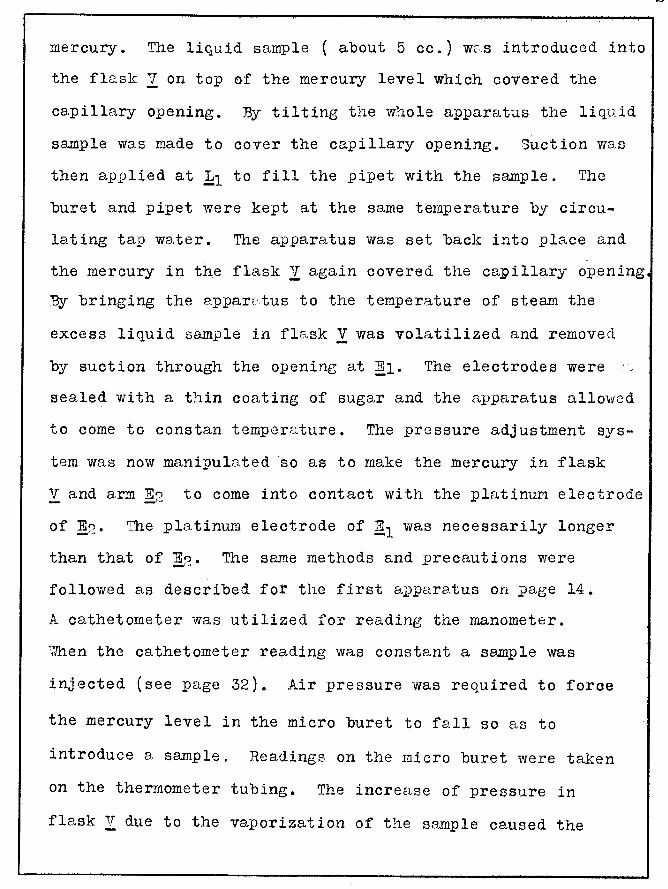
Beadings were taken along the entire length of the lower
thermometer tubing. The volume of mercury obtained was
plotted against the lower thermometer readings since the
original reading remained 170 for all results. See page
28 for the graph.
All glass parts of the apparatus with the exception
of the buret were constructed of pyrex glass. The entire
buret was constructed of soft glass.
In order to suspend the flask inside the thermobath a
large rubber stopper had to be cut to fit the water jacket
about the pipet. Since this diameter \vas 1. 5 inches, a
borer could not be obtained. The following procedure was
employed. A hole was drilled in the center with a cork

, 122 :1,.
, 12 1 7
p •
0 H ~ , 12 09
. 12 05
. 119 3
. 118 9
. 118 5 =n
·118 1
· !7
'f-W-
=
jj
H+T;
~tRJ ff;;i
tr
'-ttl tl-1'}
m
BURET
li-t
. :tt
IF
1 4
B
I:
~ !±tt l+l
li=f:j:j:Ji: .
. 60
• +I
L4 l
"" sm t
~ tt I!
B
rmrm I ~;till 12 0 1 00
H=fti ::;n
.UJ
j:jfl m:; +H
j'
borer. A coping saw was inserted in this hole and a straight
cut made to the circumference of the desired circle. Two
iron washers of 1.5 inches in diameter were placed on each
side of the stopper and mc:,,de perma.nent with a bolt and nut.
P"<J following the washers the coping saw cut a clean hole in
the stopper.
'T'o give further supJ.)ort to the flask, the arm E2 \vas
fastened to the permanent pB.rt of the top of the therrnoj acket.
The thermojacket was covered with a 0.5 inch board of celotex
insulating material on the exposed sides and top. As in the
previous ap?aratus the greatest problem was to seal the fine
capill9.ry tip of the pipet into the flask V at the position
marked 0 on the diagram. The procedure consisted insetting
everything into place with the capillary tip just entering
the fla.sk. The apparatus was tilted almost 180° so tha.t the
pipet and tip were perpendicular to the table. De Rhotinsky
cement was cut into a fine powder and blown through the water
outlet of the pipet jacket. It wa.s forced to settle at 0
28
about the fine capills.ry. Steam was circ;.llated for two hours
in the thermobath and at the end of this time suction was
applied from the flask y side to pull the softened De Khotinsky
into the capillnry to seal it.
Due to many unsuccessful attempts to seal the capillary
tip without brea.ding it into the flask an improvem(~nt was
attempted. An impression of the glass surface on the pipet
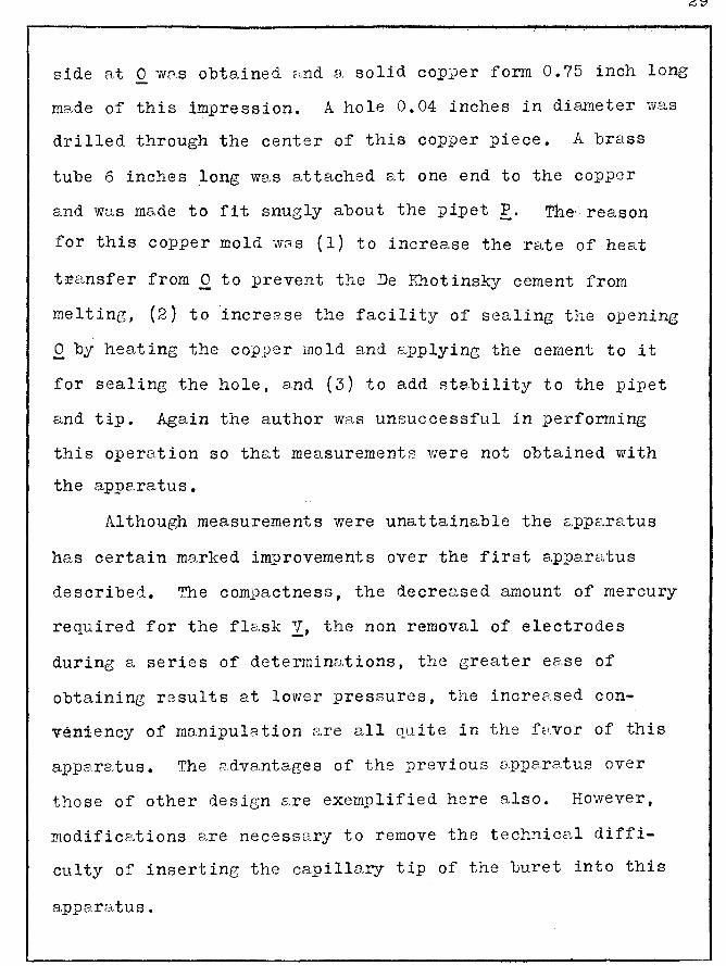
side at 0 vms obtained ;:,nd a solid copper form 0. 75 inch lone;
mc:·,de of this impression. A hole 0.04 inches in diameter vvas
drilled through the center of this copper piece. A brass
tube 6 inches long was attached at one end to the copper
and was made to fit snugly about the :pipet P. Thereason
for this copper mold was (1) to increase the rate of heat
t:Fansfer from 0 to prevent the De Kh.otinsky cement from
melting, (2) to 'increase the facility of sealing the openine;
0 by heating the copper mold and applying the cement to it
for sealing the hole, and (3) to add stability to the pipet
and tip. Again the author was unsuccessful in performing
this operation so that measurements were not obtained with
the apparatus.
Although measurements were unattainable the e;,pparatus
has certain marked improvements over the first apparatus
described. The compactness, the decreased amount of mercury
required for the fla.sk i.J, the non removal of electrodes
during a series of determinD.tions, the greater ea.se of
obtaining results at lower pressures, the increased con
veniency of manipulation are all quite in the fHvor of this
apparatus. The c:.dvantages of the previous C:J.pparatus over
those of other design s,re exemplified here also. However,
modifications 8.re necessary to remove the technical diffi
culty of inserting the capillary tip of the buret into this
apparatus.
29
R ·~.-u =:::;-;======~
lla11o111eter s
v
,. I I
1[.-::-.::=J ri - ~ '
. If
o· "'
H '\: ',

0V
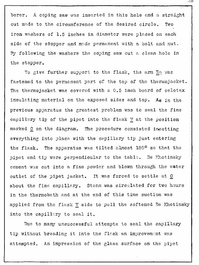
APP ~B.ATUS NUM13ER 3
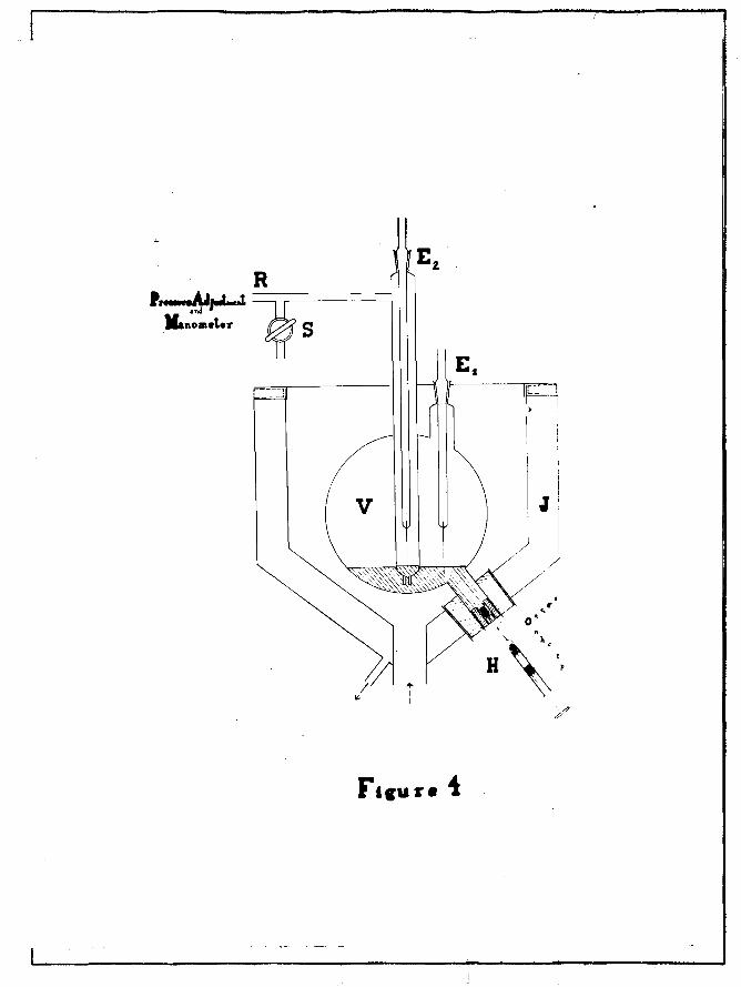
The apparatus was designed by Dr. A. P. D<Jvis and is
illustrated in Figure 4. It differs from the previous
a.pparatus in that the micro buret has been replaced by a
new system of introducing the sample. A glass hypodermic
needle was utilized in inserting the sample into the flask
V. The weight of sample we.s obtained by vveighing the needle
immediately before 2'"nd after the injection.
The hypodermic needle H, as illustrated, was of the
type used for injecting concentrated Pollen Antigen produced
by the Lederle Lab. Inc., New York. As shown, n is the
metal needle one inch long with a hole of less than 0.1 rnm
in diameter, c is a rubber dam with 8. small hole in its
center, 1 is the glass tube 1.75 inches in length, and E
is a rubber plunger on a metal rod.
The procedure was as follows. About 100 cc. of mercury
was inserted into flask V <:-3.nd the electrodes sealed with
De Rhotinsky cement. Steam was circulated about the flask
using the same thermojacket as described in the previous
appare.tus. 'llhen the temperature became constant the
constant volmne point was regulated, as previously des
cribed, and the readings on t~e m~nometer were observed with
tne ca.thetometer. The accurB.cy of the rea dings on the
cathetometer are given on the following page, table 12.
Before each readine; the constc:mt volume odjustment Vle.s
performed.
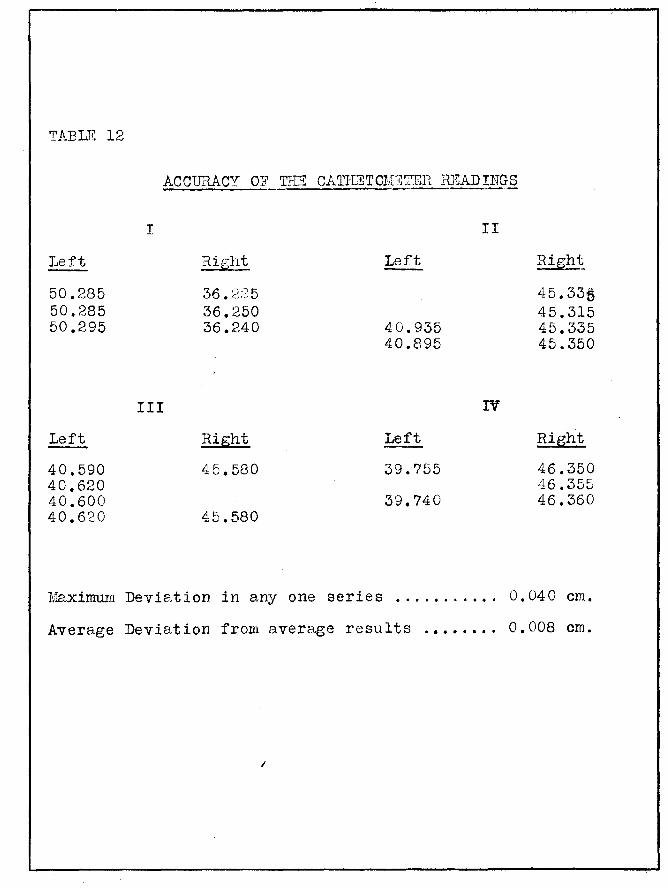
TABLB 12
ACCURACY 01!' THE CATI-IETOlnT1~11 ~'-DADUTGS
Left
50.285 50.285 50.295
Left
40.590 40.620 40.600 40.680
I
III
Right
36. 2:?5 36.250 36.240
Right
45.580
45.580
l~xinnun Deviation in any one series
Left
4 0. 935 40.895
Left
39.755
39.740
II
IV
Righ~
45.331) 45.315 45.335 45.350
Right
46.350 46.355 46.360
0.040 em.
Average Deviation from average results .•••.••. 0.008 em.
/

The hypodermic needle was filled with the desired amount
of readent Benzene. The benzene remaining in the metal needle
was pulled back into the glass tube to prevent evaporation
losses. Consequently a small amount of air was trapped in
the needle which was inserted which was inserted into the
flask. The error involved is inappreciable in the determin
ations. Before weighing the tube and sample, the catheto
meter readings were taken and then the sample weighed and
immediately introduced into the appara.tus at .Q. S is a
rubber stopper, £ is part of the glass tube t of the needle,
£1 is the rubber dam, ~ is a piece of capillary tubing so
arranged that when the needle was inserted the point follows
directly into the hole in £1· Ho mercury was lost through
£1 by leaking as the glass tube E. kept the hole in .£1 closed
when the needle was not inserted.
After injecting the sample as re,pidly a,s possible, the
hypodermic needle w<:::ts weighed and the rubber parts separated
to prevent too great a swelling and stickine to the tube as
the benzene had this effect on the rubber parts. Sometimes
a small globule of mercury was found in the needle after
an injection mB,king it necessary to separc.te and weigh it to
obtain the true weight of the sample. This globule came
from the mercury in the flask V when the needle was inserted
into it. The constant volume point was adjusted and the
cathetometer readines recorded. The temperature of the sterun
was also read.
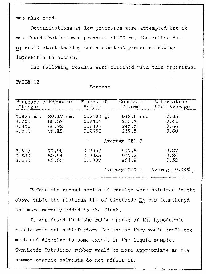
Determinations at low pressures were attempted but it
was found that below a pressure of 66 em. the rubber dam
.£1 would st&rt leaking and a constant pressure reading
impossible to obtain.
The following results were obtc;ined with this apparatus.
TABLE 13
Pressure Change
7.825 8.205 8.840 8.250
6.615 9.680 9.350
em.
.. ,_. Pressure
80.17 88.39 66.92 75.18
?7.95 80.94 82.05
em.
:Benzene
Weight Sample
0.2493 0.2634 0.2807 0.2653
0.2037 0.2983 0.2907
of Constant Volume
g. 948.5 cc. 955.7 945.5 957.5
Avervge 951.8
917.6 917.9 924.9
Average 920.1
% Deviation from Average
0.35 0.41 0.66 0.60
0.27 0.24 0.52
Average 0.44%
:Before the second series of results were obtained in the
above table the ;platinum tip of electrode !.? was lengthen~d
e.nd more mercury added to the flask.
It was found that the rubber parts of the hypodermic
needle were not satisfactory for use as they would swell too
much e.nd dissolve to some extent in the liQuid se.mple.
Synthetic ~uta,diene rubber would be more appropriate as the
common organic solvents do not affect it.

DISCUSSION Alill COlTCLUSIOlil"
From the results indicated in the first and t~ird
apparatus the experimental determinations of the volume
proved to be more exact in the third method. The average
deviation of the first method was 0.92% as compared to 0.44%
for the third. The introduction of the cathetometer in the
thi~d rr.ethod wc;.s e. big factor in this improvement. This is
evident from 8. co:m.ps.rison of the manometer cmd cathetometer
accurc;.cy determinations.
l:c;.nometer Cathetometer
Average Deviation . . . . . 0.023 em. 0.008 em.
Maximum Deviation . . . . . 0.12 em. 0. 040 em.
It was unfortunate that results could not be obtained
with the second apparatus, for the most important feature,
that of introduction of sampa.es from H micro buret through
a fine capillary, could not be comps.red to the direct
weighing method 8S illustrated in the la.st apparc.1.tus.
However, frorn the foregoing the method of introduction
of s. sample using the micro buret and caiJille,ry tip in the
first apparatus was entirely satisfs.ctory from the viewpoint
of assembling, modifications were necessary which resulted
in constructing the second apparatus and then the third.
In the original sts.tement of the problem it was hoped
to make an apparc:.tus with e.ccuracy approaching the Dunw s
3
method and with the conveniency of mc:.nipulation of the Victor
Meyer apparo_tus. The accuracy of the last apparatus is
comparable to the results of A. Schulze (see page 5, tEble 2)
. using the Dumas method. Schulze's average error wc:~s 0.42%
as compared to 0.44%' for the last apparatus. The conveniency
of the third appars.tus even exceeds that of the Victor :Meyer
methods.
It was hoped that the method of limiting density could
be used to calcula.te molecv) .. ar weights. In this the author
failed to obtain results at sufficiently low pressures to
warrant the use of the limiting density method due to
technict;;tl difficulties encountered in the appo~ratus.

BIBLIOGRAPHY
.. 1 Meyer, Victor. " Dampfdichtebestinunung". :Ber. Deutsch.
Chem. Gesell., 10, 2068 (1877)
2 J'.feyer, Victor. " Zur Dampfdichte bestimmung " Ber. Deutsch. Chem. Gesell., 11, 1867 (1978)
3 Meyer, Victor and Carl Meyer. "v~rfahren zur :Bestimmung der Dampfdichte oberhalb 440 siedender Kerper, sowie solcher Substanzen, welcher Quecksilber oder Wood' sches Metall angreifen." :Ber. Deutsch Chern. Gesell., 12, 2204 (1879) --- ----"~estimmung der Ds~pfdichte einiger unorganischer Kerper." Ber. Deutsch. Chem. Gesell., 12, 609 (1979) »Bestimmung der ~a~pfdichte einiger unorganischer Kerper. bei"-seb.r hoch Temperature." :Ber. Deutsch. Chem. Gesell., 12, 1112 (1879) ---
4. Dumas, J". B. A. "Memo ire sur quelques Points de la. Theorie Atomistique." Ann. de Chimie et de Physique, 33, 337 (1826)
5 Schulze, A. "Genaue Dampfdichtebestimmungen von einigen flussigen Kohlenstoffverbindungen." Physik. Zeit., 14, 922 (1913) --
6 Baxter, G .P. and H. VI. Sta.rkweather. ''Density, Compressibility and atomic weight of Nitrogen." Proc. Natl. Acad. Sci. u.s., 12, 703 (1926)
7 Berthelot, Daniel. "Sur la determination rigoureuse des poids molecularies des gaz en partant de leurs densites et de l'ecart que celles- ci presentent par rapport a la loi de litTariot te." Compt. Rend., 126, 954 (1898) --"TJber den Wahrscheinlichsten Wert der fur den Zustand Voll kommener Gase Charakteristischen Konstante R." Zeit. Elektro., 34, 621 (1904)
9 Weiser, H. J3. "A Modified 1T. IL:eyer Apparatus for the Determination of Yapor Densities." J"ourn. of Phys. Chem., 20, 532 (1916) -
M:acinnes, D.A. and R.G. Kreiling. '' An Improved Victor Keyer Vapor·Density Apparatus.·• J". Jun. Chem. Soc., 39, 2350 (1917)
11 Lumsden, J. S. "A new Vapor Density Apparatus.n Journ. of Chem. Soc., 83, 342 (1903)
12 Gregory, H. and C.T. Archer. "Thermal Conductivity of Gases." Phil. I~"gazine, 111 !, 593 (1926)
...,,

The thesis, "An Apparatus for Molecular
Weight Determinations", written by Philip A.
Lefrancois, has been accepted by the Graduate
School with r ef~rence to form.. and by the
readers whose names appear below. with refer
ence to content. It is, therefore. accepted in
partial fulfillment of the requirements for the
degree of Master of Arts.
Ardith P. Davis. Ph.D.
George M. Schmeing, Ph.D.
March :n. 1940
March 20. 1940
Related Documents


